CN203184817U - Spot welding head for welding varnished wire - Google Patents
Spot welding head for welding varnished wire Download PDFInfo
- Publication number
- CN203184817U CN203184817U CN 201320087251 CN201320087251U CN203184817U CN 203184817 U CN203184817 U CN 203184817U CN 201320087251 CN201320087251 CN 201320087251 CN 201320087251 U CN201320087251 U CN 201320087251U CN 203184817 U CN203184817 U CN 203184817U
- Authority
- CN
- China
- Prior art keywords
- welding
- connecting portion
- weld part
- soldering tip
- electrode shanks
- Prior art date
- Legal status (The legal status is an assumption and is not a legal conclusion. Google has not performed a legal analysis and makes no representation as to the accuracy of the status listed.)
- Withdrawn - After Issue
Links
Images
Abstract
The utility model discloses a spot welding head for welding a varnished wire. The spot welding head is of an integrated structure and comprises two electrode handle parts. An insulation gap is formed between the two electrode handle parts. The bottoms of the two electrode handle parts are connected together through a welding part. A bent-strip-shaped reinforcing connecting part is integrally formed in the insulation gap. The two ends of the reinforcing connecting part are respectively connected to the positions, close to the welding part, of the two electrode handle parts. The resistance of the reinforcing connecting part is larger than the resistance of the welding part. The spot welding head for welding the varnished wire overcomes the shortcomings in the prior art, is stable in structure and long in service life, guarantees welding reliability, and is simple in structure, easy to machine and manufacture and capable of being machined in a batch mode.
Description
Technical field
The utility model relates to the electronic spot welder technical field, the some soldering tip that is specifically related to use on a kind of electronic spot welder.
Background technology
In electronics industry, in the microelectronics industry, often use electronic spot welder that enamel-covered wire is welded on the various metal levels, have and need not to remove the advantage that insulated paint just can directly weld, can be applied to the welding of high frequency communication components and parts, the welding of SMD transformer lead-in wire, the welding of chip inductor coil, the welding of Microspeaker lead-in wire, the welding of buzzer lead-in wire, the welding of receiver lead-in wire, the welding of loudspeaker lead-in wire, the welding of earphone wire, the welding of antenna lead, microphone, the news Chinese percussion instrument, the welding of Earphone with microphone lead-in wire, the welding of vibrating motor coil, micro motor, components and parts weld with the contact of the various small coil electronic devices and components such as welding between the PCB on the module.
During electronic spot welder work, point soldering tip and host power supply form the loop, point soldering tip bottom tip is that weld part is because resistance is bigger, electric current by the time produce high temperature at weld part, the part of insulated paint is burnt, remainder is shunk back to two ends, expose metal wire, a large amount of electric currents on the weld part transfer to flow into bare metal line and metal wire substrate, and electric energy is converted into heat energy, and moment is realized two-part welding.In the existing electronic product process, because some electronic component is subjected to structure influence, the weld space is narrow and small, so that the weld part at some soldering tip tip must be done is very little, and owing to insulate between two electrode shanks of some soldering tip, only depends on tiny weld part to connect.When being installed on the welding machine installation portion respectively owing to two electrode handle portions on the one hand, both may produce relative distortion, make the weld part that is connected between the two be subjected to a distortion power, during on the other hand owing to the spot welding of some soldering tip, has welding pressure between weld part and the weldment, therefore when continuous rapid welding, weld part is easy to damage fracture, the spot welding number of times seldom, the life-span is low, can not satisfy the requirement that transfer matic is produced.In the prior art, the design of filling insulating cement in the clearance for insulation between two electrode shanks is arranged, the general handwork spot welding that is used for poor efficiency, and insulant is influential to the product welding quality in the welding process, fraction defective is higher, the fragile welding function that loses of weld part can't be applied in the continuous production of transfer matic.
The utility model content
Technical problem to be solved in the utility model is: overcome the deficiencies in the prior art, provide the welding enamel-covered wire of a kind of Stability Analysis of Structures, long service life with the some soldering tip, guaranteed soldering reliability, and put the simple in structure of soldering tip, processing and fabricating is very easy to, but batch machining.
For solving the problems of the technologies described above, the technical solution of the utility model is: a welding enamel-covered wire point soldering tip, be the integral piece structure, comprise two electrode shanks, form clearance for insulation between described two electrode shanks, the bottom of described two electrode shanks links together by weld part, be integrally formed with the reinforcement connecting portion of bending strip in the described clearance for insulation, the two ends of described reinforcement connecting portion are connected to the position of close described weld part on described two electrode shanks, and the resistance of described reinforcement connecting portion is greater than the resistance of described weld part.
As a kind of optimized technical scheme, described reinforcement connecting portion is U-shaped, described U-shaped is strengthened the top of connecting portion away from described weld part, two ends of described U-shaped reinforcement connecting portion are connected to the position of close weld part on described two electrode shanks, and the intermediate gap that described U-shaped is strengthened connecting portion extends to described weld part.
As a kind of optimized technical scheme, the top that described U-shaped is strengthened connecting portion flushes with the top of described two electrode shanks.
As another kind of optimized technical scheme, described reinforcement connecting portion is V-arrangement or camber line shape.
As a kind of optimized technical scheme, the width of described reinforcement connecting portion is similar to the width of described weld part.
After having adopted technique scheme, the beneficial effects of the utility model are: (1) of the present utility model some soldering tip, strengthening the connecting portion one is machined in two clearance for insulations between the electrode shank, therefore, whole some soldering tip can make through operations such as cutting processing with tungsten plate or the molybdenum plate of a monoblock, be very easy to realize, can produce in enormous quantities, improved the production efficiency of some soldering tip; (2) of the present utility model some soldering tip, the two ends of strengthening connecting portion are connected to the position of close weld part on two electrode shanks, strengthening connecting portion and weld part is equivalent to form two parallel resistances in the bottom of two electrode shanks, and make and strengthen the resistance of connecting portion greater than the resistance of weld part, therefore strengthening connecting portion can not cause two short circuits between the electrode shank.On this basis, have two tie points up and down between the whole some soldering tip both sides, the relative distortion power that two electrode shanks produce when installing, application point are transferred to the end of strengthening connecting portion by weld part; And in the welding process, welding pressure is shared jointly by weld part and reinforcement connecting portion, therefore, strengthen connecting portion weld part has been played booster action, in the welding process, the life-span of weld part is heightened significantly, and the spot welding number of times is brought up to 30,000 times to 80,000 times by original 10,000 times, the transfer matic continuous welding is reliable and stable, welding effect is also more satisfactory, and the bonding force test has reached requirement, and is reliable and stable, failure welding such as can not come off, the weld appearance form is good.
Description of drawings
Below in conjunction with drawings and Examples the utility model is further specified.
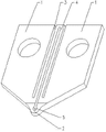
Fig. 1 is the structural representation of the utility model embodiment.
Among the figure: 1. electrode shank, 2. weld part, 3. clearance for insulation is 4. strengthened connecting portion, 5. through hole.
The specific embodiment
As shown in Figure 1, a kind of welding enamel-covered wire point soldering tip, integral body is the integral piece structure, comprises that the bottom that forms 3, two electrode shanks 1 of clearance for insulation between 1, two electrode shank 1 of two electrode shanks links together by weld part 2.In clearance for insulation 3, be integrally formed with the reinforcement connecting portion 4 of bending strip, the two ends of this reinforcement connecting portion 4 are connected to the position of close weld part 2 on two electrode shanks 1, and run business into particular one or do length by strengthening connecting portion 4, make and strengthen the resistance of connecting portion 4 greater than the resistance of weld part 2.The point soldering tip of said structure can make through operations such as cutting processing with tungsten plate or the molybdenum plate of a monoblock, is very easy to realize, can produce in enormous quantities.Strengthen connecting portion 4 and be equivalent to form two parallel resistances in the bottom of two electrode shanks 1 with weld part 2, and owing to strengthen the resistance of connecting portion 4 greater than the resistance of weld part 2, therefore strengthening connecting portion 4 can not cause two short circuits between the electrode shank 1.On this basis, have two tie points up and down between the whole some soldering tip both sides, the relative distortion power that two electrode shanks 1 produce when installing, application point is transferred to the end of strengthening connecting portion 4 by weld part 2; And in the welding process, welding pressure is shared jointly by weld part 2 and reinforcement connecting portion 4, therefore, strengthen 4 pairs of weld parts 2 of connecting portion and played booster action, in the welding process, the life-span of weld part 2 is heightened significantly, and the spot welding number of times is brought up to 30,000 times to 80,000 times by original 10,000 times, the transfer matic continuous welding is reliable and stable, and welding effect is also more satisfactory.
In this implementation process, clearance for insulation 3 between two electrode shanks 1 is narrow long groove shape, corresponding, strengthen connecting portion 4 and be designed to U-shaped, this U-shaped is strengthened the top of connecting portion 4 away from weld part 2, two ends are connected to the position of close weld part 2 on two electrode shanks 1, and the intermediate gap that U-shaped is strengthened connecting portion 4 extends to weld part 2.The clearance for insulation 3 of weld part 2 tops generally is to form the breach of a sub-circular through the past material, is used for increasing the resistance of weld part 2, also is used for increasing the radiating effect of weld part 2.
In this implementation process, the top of U-shaped being strengthened connecting portion 4 flushes with the top of two electrode shanks 1, make that the length of U-shaped reinforcement connecting portion 4 is long as far as possible, make U-shaped strengthen the resistance of connecting portion 4 much larger than the resistance of weld part 2, during the work of some soldering tip, only there is very a spot of electric current to strengthen connecting portion 4 by U-shaped, can not influence the normal welding of weld part 2.The width that U-shaped is strengthened connecting portion 4 is processed into close or narrower with the width of weld part 2, is to strengthen the resistance of connecting portion 4 in order to increase U-shaped equally, realizes above-mentioned technical purpose.
Electronic spot welder has welding pressure, weldingvoltage, weld interval three groups of regulatable welding parameters.During welding, according to the line footpath of sealing wire and the different requirements of weldment, set above-mentioned three groups of parameters, when the pressure that is applied to a soldering tip reaches setting value, could trigger microswitch, make a soldering tip and host power supply form the loop turn-on current.Because it is bigger to put weld part 2 resistance of soldering tip, electric current by the time produce high temperature at weld part 2, the part of insulated paint is burnt, remainder is shunk back to two ends, expose metal wire, because the continuation effect of welding pressure, a large amount of electric currents that order about on the weld part 2 transfer to flow into bare metal line and metal wire substrate, electric energy is converted into heat energy, and moment is realized two-part welding.
Under above-mentioned instruction of the present utility model, those skilled in the art can carry out various improvement and distortion on the basis of above-described embodiment, for example: under the more roomy situation of clearance for insulation 3, can be designed to V-arrangement or camber line shape with strengthening connecting portion 4, can realize the technique effect in above-described embodiment equally.And these improvement and distortion; all drop in the protection domain of the present utility model; it will be understood by those skilled in the art that the just better the purpose of this utility model of explaining of above-mentioned specific descriptions, protection domain of the present utility model is limited by claim and equivalent thereof.
Claims (5)
1. weld an enamel-covered wire point soldering tip, be the integral piece structure, comprise two electrode shanks, form clearance for insulation between described two electrode shanks, the bottom of described two electrode shanks links together by weld part, it is characterized in that: be integrally formed with the reinforcement connecting portion of bending strip in the described clearance for insulation, the two ends of described reinforcement connecting portion are connected to the position of close described weld part on described two electrode shanks, and the resistance of described reinforcement connecting portion is greater than the resistance of described weld part.
2. welding enamel-covered wire usefulness as claimed in claim 1 is put a soldering tip, it is characterized in that: described reinforcement connecting portion is U shape, described U-shaped is strengthened the top of connecting portion away from described weld part, two ends of described U-shaped reinforcement connecting portion are connected to the position of close weld part on described two electrode shanks, and the intermediate gap that described U-shaped is strengthened connecting portion extends to described weld part.
3. welding enamel-covered wire usefulness as claimed in claim 2 is put a soldering tip, and it is characterized in that: the top that described U-shaped is strengthened connecting portion flushes with the top of described two electrode shanks.
4. welding enamel-covered wire usefulness as claimed in claim 1 is put a soldering tip, and it is characterized in that: described reinforcement connecting portion is V-arrangement or camber line shape.
5. as the described welding enamel-covered wire of the arbitrary claim of claim 1 to 4 a point soldering tip, it is characterized in that: the width of described reinforcement connecting portion is similar to the width of described weld part.
Priority Applications (1)
| Application Number | Priority Date | Filing Date | Title |
|---|---|---|---|
| CN 201320087251 CN203184817U (en) | 2013-02-26 | 2013-02-26 | Spot welding head for welding varnished wire |
Applications Claiming Priority (1)
| Application Number | Priority Date | Filing Date | Title |
|---|---|---|---|
| CN 201320087251 CN203184817U (en) | 2013-02-26 | 2013-02-26 | Spot welding head for welding varnished wire |
Publications (1)
| Publication Number | Publication Date |
|---|---|
| CN203184817U true CN203184817U (en) | 2013-09-11 |
Family
ID=49101713
Family Applications (1)
| Application Number | Title | Priority Date | Filing Date |
|---|---|---|---|
| CN 201320087251 Withdrawn - After Issue CN203184817U (en) | 2013-02-26 | 2013-02-26 | Spot welding head for welding varnished wire |
Country Status (1)
| Country | Link |
|---|---|
| CN (1) | CN203184817U (en) |
Cited By (1)
| Publication number | Priority date | Publication date | Assignee | Title |
|---|---|---|---|---|
| CN103111742A (en) * | 2013-02-26 | 2013-05-22 | 歌尔声学股份有限公司 | Spot welding head for welding enamelled wires |
-
2013
- 2013-02-26 CN CN 201320087251 patent/CN203184817U/en not_active Withdrawn - After Issue
Cited By (2)
| Publication number | Priority date | Publication date | Assignee | Title |
|---|---|---|---|---|
| CN103111742A (en) * | 2013-02-26 | 2013-05-22 | 歌尔声学股份有限公司 | Spot welding head for welding enamelled wires |
| CN103111742B (en) * | 2013-02-26 | 2015-03-11 | 歌尔声学股份有限公司 | Spot welding head for welding enamelled wires |
Similar Documents
| Publication | Publication Date | Title |
|---|---|---|
| CN207771081U (en) | A kind of Cu-AL pipe butt welding machine | |
| CN101394968A (en) | Resistance welding head and preparation thereof | |
| CN103883995A (en) | COB lamp bead easy to assemble, support used for lamp bead, method for manufacturing lamp bead and easily-assembled LED module | |
| CN205428913U (en) | Power semiconductor module | |
| CN103111742B (en) | Spot welding head for welding enamelled wires | |
| CN1139453C (en) | Electric welding head of pinpoint welding | |
| CN203184817U (en) | Spot welding head for welding varnished wire | |
| CN106465543A (en) | Electronic device | |
| CN101388352B (en) | MOSFET and linking method thereof | |
| CN201012433Y (en) | Bonding tool | |
| CN109411372A (en) | A method of based on covering copper ceramic substrate uniform current assisted sintering nano mattisolda temperature field | |
| CN204596786U (en) | A kind of power model | |
| CN114899162A (en) | Module and manufacturing method thereof | |
| CN210778574U (en) | DBC structure suitable for high-voltage power device module packaging | |
| CN202042476U (en) | Device packaging structure | |
| CN203179671U (en) | Transformer | |
| CN104916612A (en) | Power module and making method thereof | |
| CN103182598B (en) | A kind of welding method of high-power automobile-used rectifier bridge and lug plate thereof | |
| US20140021640A1 (en) | Method for electrically connecting vertically positioned substrates | |
| CN104526145A (en) | Method for interconnecting micro-socket connector fine-pitch terminal and base plate through enameled wire | |
| JP6116740B1 (en) | Flat braided wire and manufacturing method thereof | |
| EP2498290A1 (en) | Contact element and power semiconductor module comprising a contact element | |
| CN103779305A (en) | Metal connecting piece and power semiconductor module | |
| CN215911425U (en) | Power module and household electrical appliance | |
| CN220121834U (en) | MOS chip welding positioning structure |
Legal Events
| Date | Code | Title | Description |
|---|---|---|---|
| C14 | Grant of patent or utility model | ||
| GR01 | Patent grant | ||
| AV01 | Patent right actively abandoned |
Granted publication date: 20130911 Effective date of abandoning: 20150311 |
|
| RGAV | Abandon patent right to avoid regrant |