CN203044362U - Automatic screening machine for deformation of pins of connector housings - Google Patents
Automatic screening machine for deformation of pins of connector housings Download PDFInfo
- Publication number
- CN203044362U CN203044362U CN 201220637634 CN201220637634U CN203044362U CN 203044362 U CN203044362 U CN 203044362U CN 201220637634 CN201220637634 CN 201220637634 CN 201220637634 U CN201220637634 U CN 201220637634U CN 203044362 U CN203044362 U CN 203044362U
- Authority
- CN
- China
- Prior art keywords
- station
- connector shell
- manipulator
- slide
- arm
- Prior art date
- Legal status (The legal status is an assumption and is not a legal conclusion. Google has not performed a legal analysis and makes no representation as to the accuracy of the status listed.)
- Withdrawn - After Issue
Links
Images


Landscapes
- Manipulator (AREA)
Abstract
The utility model discloses an automatic screening machine for the deformation of pins of connector housings. The automatic screening machine comprises a vibrating disk mounting rack, a vibrating disk, a vibrating feeding channel, a detecting platform, a pushing mechanism, a loading manipulator, a detection mechanism, a first discharging manipulator, a non-defective product discharging channel, a second discharging manipulator and a defective product collecting box. When the pins of the connector housings are detected, the connector housings are orderly conveyed to a feeding station A at the tail end of the vibrating feeding channel when the vibrating disk is in dithering, the connector housings are conveyed to a designated suction feeding station B by the pushing mechanism, the connector housings are conveyed to a detection station C by the loading manipulator, the detection mechanism is used for detecting the pins of the connector housing, when the pins are good in quality and free from deformation, the connector housings are sucked to a first discharging station D by the first discharging manipulator and discharged out by the non-defective product discharging channel, when the pins of the connector housing are deformed, the connector housings are clamped to a second discharging station E by the second discharging manipulator so as to put in the defective product collecting box.
Description
Technical field
The utility model relates to electric connector quality detection apparatus art, refers in particular to a kind of connector shell pin distortion automatic screening machine.
Background technology
Along with the development of society, various connectors have obtained using widely in different electronic equipment (as equipment such as electronics, computers), and the demand of connector is very big.Whether connector generally is to be inserted into by pin to weld on the circuit board with fixing, in case the pin distortion just can't be inserted in the weld bond of pcb board, therefore detect each pin of connector shell and be out of shape extremely important.
At present the quality testing major part of domestic large batch of connector shell pin is directly to observe by human eye and judge.Large batch of connector product detects often needs a large amount of employees to carry out the work of high duplication.This product defects detection mode has many weak points, and at first, human eye works long hours and works under high light source, and is very easily tired, judges by accident easily and fails to judge; Secondly, because everyone is different with the degree of understanding to the awareness of standard, the standard of subjective judgement is also different, is difficult to quantize, and therefore in testing process, does not have unified examination criteria; At last, because the workload that detects is big, repeatability is high, serious to the injury of human eye.And people can't with the naked eye carry out at all continuously and stably, and not only efficient is lower, and working strength is big, and also corresponding uprising of the human cost of product.
The utility model content
In view of this, the utility model is at the disappearance of prior art existence, its main purpose provides a kind of connector shell pin distortion automatic screening machine, automatic detection to the connector shell pin, and after detection, non-defective unit and defective products are classified automatically, complete machine is realized automatically operating, and need not manually-operated, effectively boost productivity, save time and human cost.
For achieving the above object, the utility model adopts following technical scheme:
A kind of connector shell pin distortion automatic screening machine comprises
One vibrating disk installing rack;
One vibrating disk is installed on the vibrating disk installing rack;
One vibration feeding channel is connected in vibrating disk;
One monitor station is positioned at the next door of vibrating disk installing rack, and this monitor station is provided with feed station successively, draws the material loading station, detects station, the first blanking station and the second blanking station at the feeding track;
One is used for connector shell is delivered to the pusher of drawing the material loading station from feed station, be installed on the monitor station and corresponding feed station, this pusher comprises the pusher cylinder, promotes slide block and pusher passage, this pusher passage and aforementioned vibration feeding channel are refuted and are connect, this promotion slide block is connected in the piston rod of pusher cylinder and extend into movably in the pusher passage, and the head end that promotes slide block is provided with one and is used for blocking connector shell and slidably reciprocates in feed station and draw stopper slot between the material loading station;
One feeding manipulator, be installed on the monitor station and the corresponding material loading station of drawing, this feeding manipulator comprises the mechanical arm mobile by two motor-driven and is used for that connector shell is delivered to the suction that detects station from absorption material loading station chews mechanism, and the end that mechanism is connected in mechanical arm is chewed in this suction;
One testing agency, be installed on the monitor station and the corresponding station that detects, this testing agency comprises detects seat and for detection of the connector shell infrared probe of non-defective unit whether, this detection seat is provided with the jack for the pin insertion of connector shell, and also be provided with on the detection seat and can be connected the through hole that the device shell blocks, this infrared probe is installed in the through hole;
One is used for first of non-defective unit blanking sends manipulator, be installed on the monitor station and the corresponding first blanking station, this first is sent manipulator and comprises by two motor-driven mobile mechanical arm and be used for connector shell is delivered to the suction of the first blanking station and chewed mechanism from detecting station that the end that mechanism is connected in mechanical arm is chewed in this suction;
One is used for second of defective products blanking sends manipulator, be installed on the monitor station and the corresponding second blanking station, this second sends that manipulator comprises by cylinder and motor-driven and mobile mechanical arm and the connector shell that is used for failing are delivered to the feeding clip mechanism of the second blanking station, and this feeding clip mechanism is connected in the end of mechanical arm.
Preferably, described pusher passage is located on the feeding seat that is fixed in monitor station, this pusher passage connects with vertical the refuting of vibration feeding channel, is provided with one in feeding seat and is communicated with pusher passage and the breach that vibrates feeding channel, also is provided with one in the top of this feeding seat and pushes down the cover plate that promotes slide block.
Preferably, described feeding manipulator and first is sent manipulator and is installed on the same fixed support, and feeding manipulator and first to send the structure of manipulator identical.
Preferably, described first mechanical arm of sending manipulator comprises lifting arm and translation arm, and described suction is chewed mechanism and comprised inhaling to chew mount pad and to be connected in and inhale the suction of chewing in the mount pad and chew that this suction is chewed mount pad and is fixed on the translation arm.
Preferably, this lifting arm comprises first motor, Connection Block, longitudinal sliding block and vertical chute, this first motor is installed in fixed support, the main shaft of first motor is joint chair in succession, this vertical chute is located on the fixed support, and this longitudinal sliding block is fixed in Connection Block and can be sticked in vertical chute up and downly.
Preferably, described translation arm comprises second motor, slide, cross sliding clock and horizontal concrete chute, and this second motor is fixed in Connection Block, and the main shaft of second motor connects slide, this cross sliding clock is fixed in Connection Block, and this horizontal concrete chute is located on the slide and can be sticked in cross sliding clock versatilely in front and back.
Preferably, described detection seat comprises a base plate, biside plate and a top board, and each jack is located on the top board, the center that through hole surrounds between each jack.
Preferably, the described second mechanical arm Bao Kuo Transverse that sends manipulator walks arm and erects away arm , Transverse and walk arm and erect away arm to be erected on the holder, and this feeding clip mechanism is connected in and erects away on the arm.
Preferred Suo Shu Transverse walks arm and comprises cylinder, Connection Block, first slide, transverse slider and horizontal concrete chute, this cylinder is installed on the holder, the piston rod of cylinder is joint chair in succession, Connection Block is fixed in first slide, this transverse slider directly is formed at the top of holder, and this horizontal concrete chute is located on first slide and can be fastened on the transverse slider slidingly.
Preferably, the described arm that erects away comprises drive motors, second slide, vertical slide block and vertical chute, this drive motors is fixed in Connection Block, the main shaft of drive motors is connected in second slide, this vertical slide block is located on first slide, and this vertical chute is located on second slide and can be fastened on the longitudinal sliding block up or down.
The utility model compared with prior art has tangible advantage and beneficial effect, particularly, as shown from the above technical solution, whether this device identification connector shell pin quickly and accurately exists distortion, and defective product and non-defective unit classified, can replace the operation that tradition adopts eye-observation and judgement, thus many deficiencies of avoiding human eye to judge, and whole-course automation, easy to operate, reduce labour intensity greatly, not only improved detection efficiency and accuracy, and detection speed is fast, effectively shorten life cycle of the product, reduce cost, improved production efficiency and product percent of pass greatly, strengthen Enterprises'Competitiveness.
For more clearly setting forth architectural feature of the present utility model and effect, come the utility model is elaborated below in conjunction with accompanying drawing and specific embodiment.
Description of drawings
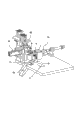
Fig. 1 is the assembling schematic perspective view of the embodiment of the utility model;
Fig. 2 is the rear view of Fig. 1;
Fig. 3 is the vertical view of Fig. 1;
Fig. 4 is the front view of Fig. 1;
Fig. 5 is the schematic diagram that pusher among the embodiment of the utility model, feeding manipulator and first are sent manipulator;
Fig. 6 is the structural representation of pusher among the embodiment of the utility model;
Fig. 7 is the exploded view of pusher among the embodiment of the utility model;
Fig. 8 is another visual angle figure of Fig. 5;
Fig. 9 is the exploded view of Fig. 8;
Figure 10 is the schematic diagram that feeding manipulator and first is sent manipulator among the embodiment of the utility model;
Figure 11 is first schematic diagram of sending manipulator among the embodiment of the utility model;
Figure 12 is the exploded view of Figure 11;
Figure 13 is the structural representation of testing agency among the embodiment of the utility model;
Figure 14 is the schematic diagram of detected state among Figure 13;
Figure 15 is second structural representation of sending manipulator among the embodiment of the utility model;
Figure 16 is the first decomposition texture schematic diagram of Figure 15;
Figure 17 is the second decomposition texture schematic diagram of Figure 15.
The accompanying drawing identifier declaration:
1, vibrating disk installing rack 2, monitor station
3, connector shell 4, display
10, vibrating disk 20, vibration feeding channel
21, brace table
30, pusher 31, feeding seat
311, breach 32, pusher passage
33, pusher cylinder 331, promotion slide block
332, stopper slot 34, cover plate
35, cylinder block
40, feeding manipulator
50, testing agency 51, detection seat
511, base plate 512, side plate
513, top board 52, jack
53, through hole
60, first send manipulator 61, lifting arm
611, first motor 612, Connection Block
613, longitudinal sliding block 614, motor attaching parts
62, translation arm 621, second motor
622, slide 623, cross sliding clock
624, horizontal concrete chute 625, connecting portion
626, mechanism is chewed in fixed block 63, suction
631, suction is chewed mount pad 632, is inhaled and chew
64, fixed support 641, vertical chute
70, non-defective unit is sent passage
80, second send manipulator 81, holder
82,, Transverse walks arm 821, cylinder
822, Connection Block 823, first slide
824, transverse slider 825, horizontal concrete chute
826, connecting portion 827, connector
828, gear
83, erect away arm 831, drive motors
832, second slide 833, vertical slide block
834, vertical chute 835, connecting portion
836, connector 84, feeding clip mechanism
90, defective products collecting box
A, feed station B, absorption material loading station
C, detection station D, the first blanking station
E, the second blanking station.
The specific embodiment
Please refer to Fig. 1 to shown in Figure 4, it has demonstrated the concrete structure of the preferred embodiment of the utility model, this connector shell pin distortion automatic screening machine includes vibrating disk installing rack 1, be installed in the vibrating disk 10 on the vibrating disk installing rack 1, vibration feeding channel 20, this screening machine also includes monitor station 2, be installed on the pusher 30 on the monitor station 2, feeding manipulator 40, testing agency 50, first sends manipulator (being that non-defective unit is sent manipulator) 60, non-defective unit is sent passage 70, second sends manipulator (being that defective products is sent manipulator) 80, defective products collecting box 90.This vibration feeding channel 20 rides between vibrating disk 10 and the monitor station 2, have feed station A at monitor station 2, draw material loading station B, detect station C, the first blanking station (being non-defective unit blanking station) D and the second blanking station (being defective products blanking station) E, the motion track when this pusher 30, feeding manipulator 40, testing agency 50, first send manipulator 60, second and send manipulator 80 and detect according to connector shell 3 sets gradually.When connector shell 3 pins are detected, vibrating disk 10 is fitly delivered to connector shell 3 on the feed station A of vibration feeding channel 20 ends when shake, pusher 30 is delivered to connector shell 3 the absorption material loading station B of appointment, by feeding manipulator 40 connector shell 3 is delivered to detection station C, pin with 50 pairs of connector shells 3 of testing agency detects, when each pin quality does not well have distortion, send manipulator 60 with first and be drawn to the first blanking station D, sending passage 70 by non-defective unit sends, when connector shell 3 pins have distortion, send manipulator 80 with second and press from both sides to the second blanking station E, put in the defective products collecting box 90.
Wherein, this vibrating disk installing rack 1 is positioned at the next door of monitor station 2, because in the time of in working order, vibrating disk installing rack 1 degree of jitter is bigger, and monitor station 2 needs higher stationarity, thus vibrating disk installing rack 1 and monitor station 2 should not establish jointly as a whole, preferably split setting, guarantee that vibrating disk 10 can not influence each mechanism on the monitor station 2 when 1 shake of vibrating disk installing rack, make each mechanism's preferable realization of energy performance separately.
In the present embodiment, an end of this vibration feeding channel 20 is connected the side of vibrating disk 10, and the other end extends to the feed station A of monitor station 2, and prop up with a brace table 21 that is installed on vibrating disk installing rack 1 at the middle part of this vibration feeding channel 20.Because the structure of vibrating disk 10 and vibration feeding channel 20 is known, does not repeat them here.
Shown in Fig. 5,6,7, the connector shell 3 that described pusher 30 is used for that vibrating disk 10 is sent here is pushed into from feed station A draws material loading station B, draws and transmits for feeding manipulator 40.This pusher 30 comprises a feeding seat 31, is located at pusher passage 32 and a pusher cylinder 33 on the feeding seat 31.This feeding seat 31 is fixed on the monitor station 2, and this pusher passage 32 connects with aforementioned vibration feeding channel 20 vertical refuting, and draws the front end that material loading station B is located at this pusher passage 32.In the present embodiment, be provided with the breach 311 that pusher passage 32 is communicated with aforementioned vibration feeding channel 20 in a side of feeding seat 31.This pusher cylinder 33 is fixed on the monitor station 2 by a cylinder block 35, the piston rod of pusher cylinder 33 is connected with the promotion slide block 331 of a T font, promoting slide block 331 is installed in the pusher passage 32, and the front end that promotes slide block 331 has a stopper slot 332, this stopper slot 332 can be inserted a connector shell 3 just, delivers on the absorption material loading station B with promoting slide block 331 thereby connector shell 3 is presented in the stopper slot 332.In addition, also be provided with a cover plate 34 in the top of this feeding seat 31, be used for pushing down promotion slide block 331 and each connector shell 3 by pusher passage 32, guarantee only to take the air line when each connector shell 3 keeps neatly carrying and making promotion slide block 331 to be pushed, can sideslip.
In the feeding process of connector shell 3, the action of this pusher 30 is as follows: each connector shell 3 is from left to right carried continuously, breach 311 by feeding seat 31 is sent in the pusher passage 32, when sensor detects connector shell 3 and is positioned at feed station A (when placing the stopper slot 332 that promotes slide block 331 front ends), this pusher cylinder 33 just promotes slide block 331, by promoting slide block 331 connector shell 3 is delivered to absorption material loading station B by feed station A.This stopper slot 332 is active in feed station A back and forth and draws between the material loading station B, it is carried out spacing because stopper slot 332 is clamped connector shell 3, and the conveying of connector shell 3 steadily can be rocked, and transfer position is accurate, does not have deviation phenomenon.
Shown in Fig. 8,9,10, described feeding manipulator 40 and first is sent manipulator 60 and is shared a fixed support 64, and this fixed support 64 is fixed on the monitor station 2, and the right side of fixed support 64 and rear side are equipped with vertical chute 641.This feeding manipulator 40 is installed in vertical chute 641 of rear side of fixed support 64, it can make progress, downwards, left, move right, deliver to detect on the station C with the connector shell 3 that will draw material loading station B and detect.Described first sends in vertical chute 641 on right side that manipulator 60 is installed on fixed support 64, it can make progress, downwards, forward, mobile backward, when the pin of connector shell 3 did not have distortion, this first was sent connector shell 3 that manipulator 60 will detect station C and delivers to the first blanking station D and send.
In the present embodiment, it is basic identical that feeding manipulator 40 and first is sent the structure of manipulator 60, and just the installation site is different and be used for different production processes, at this, only sending manipulator 60 with first is the explanation that example is carried out concrete structure, and the structure of feeding manipulator 40 repeats no more.
Shown in Figure 11,12, described first sends manipulator 60 comprises lifting arm 61, translation arm 62 and inhales and chew mechanism 63.
This lifting arm 61 comprises first motor 611, Connection Block 612, longitudinal sliding block 613 and aforementioned vertical chute 641; This first motor 611 is fixedly installed on the fixed platform of T font at fixed support 64 tops, this longitudinal sliding block 613 is slidably mounted in vertical chute 641, and the back side of longitudinal sliding block 613 is fixed on the Connection Block 612, one motor attaching parts 614 are arranged at these Connection Block 612 tops, are used for being connected with the electric machine main shaft that stretches out the fixed platform bottom; Take this, first motor 611 drives Connection Block 612 and rises or down maneuver, and then drives longitudinal sliding block 613 upper and lower slip in vertical chute 641.
Described translation arm 62 comprises second motor 621, slide 622, cross sliding clock 623 and horizontal concrete chute 624; This cross sliding clock 623 is located at Connection Block 612 dorsad on the side of longitudinal sliding block 613, and this horizontal concrete chute 624 is arranged on the slide 622, and also is provided with a connecting portion 625 that is used for connecting second motor 621 on this slide 622.Described second motor 621 is installed in the end of aforementioned Connection Block 612 by a fixed block 626, and the main shaft of this second motor 621 and connecting portion 625 join; Take this, second motor 621 drives slide 622 translations, drives horizontal concrete chute 624 forward and backward translation on cross sliding clock 623.
Described suction is chewed mechanism 63 and is comprised inhaling to chew mount pad 631 and to be connected in and inhale the suction of chewing in the mount pad 631 and chew 632, this suction is chewed mount pad 631 and is fixed on the slide 622, inhale in the present embodiment that to chew 632 quantity be two, two suctions are chewed 632 and can be held the top of electrical connector housing 3, and guarantee the balance of suction.
In the present embodiment, this Connection Block 612, motor attaching parts 614, cross sliding clock 623, longitudinal sliding block 613 and fixed block 626 are that split assembles, yet, also can be made of one the moulding syndeton.In addition, it also can be integrated formed structure that mount pad 631 is chewed in slide 622 and the suction of present embodiment, not as limit.
First to send the operation principle of manipulator 60 as follows for this: when the pin that detects connector shell 3 when the sensor of testing agency 50 does not all have distortion, this first first motor 611 of sending manipulator 60 starts, the main shaft of first motor 611 acts on lifting arm 61, when lifting arm 61 rose or descends, then translation arm 62 and suction were chewed mechanism 63 rising synchronously or are descended.The distance value program setting that this lifting arm 61 rises or descends, when treating that lifting arm 61 arrives setting value, drive translation arm 62 by second motor 621 and carry out translation, when translation arm 62 translation forward or backward, it is mobile forward or backward synchronously that mechanism 63 is chewed in this suction.Chew 632 when suction and arrive to detect station C, the connector shell 3 that pin can not had distortion holds, and moves on to the first blanking station D then, discharges connector shell 3 again, finish release after, this first is sent manipulator 60 and gets back to reset condition, waits for action next time.Certainly, the first lifting arm 61 of sending manipulator 60 and translation arm 62 also can synchronization actions, that is be when rising, move forward or after move, perhaps when descending, move forward or after move, concrete control mode is moved according to program setting.
As Figure 13 and shown in Figure 14, described testing agency 50 is fixed on the monitor station 2.This testing agency 50 comprises that one detects 51 and one infrared probe that is installed on the detection seat 51, this detection seat 51 comprises a base plate 511, biside plate 512 and a top board 513, this top board 513 is provided with several jacks 52, supplies the pin insertion of connector shell 3 to detect.In addition, also be provided with a through hole 53 on this top board 513, be used for hookup wire outside line probe; In the present embodiment, the center that this through hole 53 surrounds between each jack 53.If the pin of connector shell 3 can be inserted in the corresponding jack 52 smoothly, when blocking the infrared probe in the through hole 53, each pin that this connector shell 3 is described so is not have distortion, is non-defective unit, is defective products on the contrary.Non-defective unit is sent manipulator 60 by first and is drawn onto non-defective unit and sends passage 70, and defective products is sent manipulator 80 by second and pressed from both sides to defective products collecting box 90.
Shown in Figure 15 to 17, described second sends manipulator 80 can realize left and right, upper and lower movement, so that defective products is clipped in the defective products collecting box 90.This second is sent manipulator 80 and comprises that a holder 81, Transverse walk arm 82, erect away arm 83 and feeding clip mechanism 84.
This holder 81 is installed on the monitor station 2.
Gai Transverse walks arm 82 and comprises cylinder 821, Connection Block 822, first slide 823, transverse slider 824 and horizontal concrete chute 825, this transverse slider 824 is directly arranged in the top of holder 81, and be provided with gear 828 at the two ends of transverse slider 824, be used for blocking horizontal concrete chute 825, make it to be limited in the transverse slider 824 and slide; This horizontal concrete chute 825 is located on first slide 823, and horizontal concrete chute 825 is embedded in the transverse slider 824, and this Connection Block 822 is installed on first slide 823, and the lower end of Connection Block 822 is provided with a junction 826, is used for being connected with the piston rod of cylinder 821; This cylinder 821 is installed on the holder 81 by a connection piece 827, and the piston rod of this cylinder 821 is connected on the connecting portion 826 of Connection Block 822, takes this, and drives Connection Block 822 crosswise movements by piston rod, and it is mobile at transverse slider 824 to drive horizontal concrete chute 825.
The described arm 83 that erects away comprises drive motors 831, second slide 832, vertical slide block 833 and vertical chute 834, this vertical slide block 833 is located at first slide 823 dorsad on the side of Connection Block 822, this vertical chute 834 is located on second slide 832, and vertical chute 834 can slide up and down to be embedded in the vertical slide block 833; Be provided with a junction 835 in second slide 832, drive motors 831 is fixed in the top of Connection Block 822 by connector 836, the main shaft of drive motors 831 connects the connecting portion 835 of second slide 832, take this, drive second slide, 832 knee-actions by drive motors 831, it is mobile in vertical slide block 833 to drive vertical chute 834.
Described feeding clip mechanism 84 is installed on second slide 832, this feeding clip mechanism 84 is used for clamping the connector shell 3 that pin falls short of specifications, it is clamped and deliver on the second blanking station E by detecting station C, unclamp again, defective products connector shell 3 is encased in the defective products collecting box 90.
In addition, this connector shell pin distortion automatic screening machine also includes an electric-control system and a display 4, and electric-control system is connected with each mechanism.When each pin that detects connector shell 3 when line sensor outside the line of checkout gear is inserted in the jack 52, be non-defective unit, made first to send manipulator 60 and start by electric control system controls, connector shell 3 is drawn onto non-defective unit sends passage 70; When each pin of connector shell 3 can't be inserted into jack 52 because of distortion, be defective products, infrared ray sensor can't be sensed connector shell 3, at this moment, make second to send manipulator 80 startups by electric control system controls, connector shell 3 is pressed from both sides to the second blanking station E.Described display 4 is for the quantity that shows detected state, non-defective unit, defective products and ratio data etc.
In sum, design focal point of the present utility model is, whether this device identification connector shell pin quickly and accurately exists distortion, and defective product and non-defective unit classified, can replace the operation that tradition adopts eye-observation and judgement, thereby many deficiencies of avoiding human eye to judge, and whole-course automation, easy to operate, reduce labour intensity greatly, detection efficiency and accuracy have not only been improved, and detection speed is fast, effectively shortens life cycle of the product, reduces cost, improve production efficiency and product percent of pass greatly, strengthened Enterprises'Competitiveness.
The above, it only is preferred embodiment of the present utility model, be not that technical scope of the present utility model is imposed any restrictions, so every foundation technical spirit of the present utility model all still belongs in the scope of technical solutions of the utility model any trickle modification, equivalent variations and modification that above embodiment does.
Claims (10)
1. a connector shell pin distortion automatic screening machine is characterized in that: comprise
One vibrating disk installing rack;
One vibrating disk is installed on the vibrating disk installing rack;
One vibration feeding channel is connected in vibrating disk;
One monitor station is positioned at the next door of vibrating disk installing rack, and this monitor station is provided with feed station successively, draws the material loading station, detects station, the first blanking station and the second blanking station at the feeding track;
One is used for connector shell is delivered to the pusher of drawing the material loading station from feed station, be installed on the monitor station and corresponding feed station, this pusher comprises the pusher cylinder, promotes slide block and pusher passage, this pusher passage and aforementioned vibration feeding channel are refuted and are connect, this promotion slide block is connected in the piston rod of pusher cylinder and extend into movably in the pusher passage, and the head end that promotes slide block is provided with one and is used for blocking connector shell and slidably reciprocates in feed station and draw stopper slot between the material loading station;
One feeding manipulator, be installed on the monitor station and the corresponding material loading station of drawing, this feeding manipulator comprises the mechanical arm mobile by two motor-driven and is used for that connector shell is delivered to the suction that detects station from absorption material loading station chews mechanism, and the end that mechanism is connected in mechanical arm is chewed in this suction;
One testing agency, be installed on the monitor station and the corresponding station that detects, this testing agency comprises detects seat and for detection of the connector shell infrared probe of non-defective unit whether, this detection seat is provided with the jack for the pin insertion of connector shell, and also be provided with on the detection seat and can be connected the through hole that the device shell blocks, this infrared probe is installed in the through hole;
One is used for first of non-defective unit blanking sends manipulator, be installed on the monitor station and the corresponding first blanking station, this first is sent manipulator and comprises by two motor-driven mobile mechanical arm and be used for connector shell is delivered to the suction of the first blanking station and chewed mechanism from detecting station that the end that mechanism is connected in mechanical arm is chewed in this suction;
One is used for second of defective products blanking sends manipulator, be installed on the monitor station and the corresponding second blanking station, this second sends that manipulator comprises by cylinder and motor-driven and mobile mechanical arm and the connector shell that is used for failing are delivered to the feeding clip mechanism of the second blanking station, and this feeding clip mechanism is connected in the end of mechanical arm.
2. connector shell pin according to claim 1 is out of shape automatic screening machine, it is characterized in that: described pusher passage is located on the feeding seat that is fixed in monitor station, this pusher passage connects with vertical the refuting of vibration feeding channel, be provided with one in feeding seat and be communicated with pusher passage and the breach that vibrates feeding channel, also be provided with one in the top of this feeding seat and push down the cover plate that promotes slide block.
3. connector shell pin according to claim 1 distortion automatic screening machine, it is characterized in that: described feeding manipulator and first is sent manipulator and is installed on the same fixed support, and feeding manipulator and first to send the structure of manipulator identical.
4. connector shell pin according to claim 3 is out of shape automatic screening machine, it is characterized in that: described first mechanical arm of sending manipulator comprises lifting arm and translation arm, described suction is chewed mechanism and is comprised inhaling to chew mount pad and to be connected in and inhale the suction of chewing in the mount pad and chew that this suction is chewed mount pad and is fixed on the translation arm.
5. connector shell pin according to claim 4 is out of shape automatic screening machine, it is characterized in that: this lifting arm comprises first motor, Connection Block, longitudinal sliding block and vertical chute, this first motor is installed in fixed support, the main shaft of first motor is joint chair in succession, this vertical chute is located on the fixed support, and this longitudinal sliding block is fixed in Connection Block and can be sticked in vertical chute up and downly.
6. connector shell pin according to claim 5 is out of shape automatic screening machine, it is characterized in that: described translation arm comprises second motor, slide, cross sliding clock and horizontal concrete chute, this second motor is fixed in Connection Block, the main shaft of second motor connects slide, this cross sliding clock is fixed in Connection Block, and this horizontal concrete chute is located on the slide and can be sticked in cross sliding clock versatilely in front and back.
7. connector shell pin according to claim 1 is out of shape automatic screening machine, it is characterized in that: described detection seat comprises a base plate, biside plate and a top board, and each jack is located on the top board, the center that through hole surrounds between each jack.
8. connector shell pin according to claim 1 is out of shape automatic screening machine, it is characterized in that: the described second mechanical arm Bao Kuo Transverse that sends manipulator walks arm and erects away arm Transverse and walk arm and erect away arm to be erected on the holder, and this feeding clip mechanism is connected in and erects away on the arm.
9. connector shell pin according to claim 8 is out of shape automatic screening machine, it is characterized in that: Suo Shu Transverse walks arm and comprises cylinder, Connection Block, first slide, transverse slider and horizontal concrete chute, this cylinder is installed on the holder, the piston rod of cylinder is joint chair in succession, Connection Block is fixed in first slide, this transverse slider directly is formed at the top of holder, and this horizontal concrete chute is located on first slide and can be fastened on the transverse slider slidingly.
10. connector shell pin according to claim 9 is out of shape automatic screening machine, it is characterized in that: the described arm that erects away comprises drive motors, second slide, vertical slide block and vertical chute, this drive motors is fixed in Connection Block, the main shaft of drive motors is connected in second slide, this vertical slide block is located on first slide, and this vertical chute is located on second slide and can be fastened on the longitudinal sliding block up or down.
Priority Applications (1)
| Application Number | Priority Date | Filing Date | Title |
|---|---|---|---|
| CN 201220637634 CN203044362U (en) | 2012-11-28 | 2012-11-28 | Automatic screening machine for deformation of pins of connector housings |
Applications Claiming Priority (1)
| Application Number | Priority Date | Filing Date | Title |
|---|---|---|---|
| CN 201220637634 CN203044362U (en) | 2012-11-28 | 2012-11-28 | Automatic screening machine for deformation of pins of connector housings |
Publications (1)
| Publication Number | Publication Date |
|---|---|
| CN203044362U true CN203044362U (en) | 2013-07-10 |
Family
ID=48727360
Family Applications (1)
| Application Number | Title | Priority Date | Filing Date |
|---|---|---|---|
| CN 201220637634 Withdrawn - After Issue CN203044362U (en) | 2012-11-28 | 2012-11-28 | Automatic screening machine for deformation of pins of connector housings |
Country Status (1)
| Country | Link |
|---|---|
| CN (1) | CN203044362U (en) |
Cited By (13)
| Publication number | Priority date | Publication date | Assignee | Title |
|---|---|---|---|---|
| CN103041995A (en) * | 2012-11-28 | 2013-04-17 | 东莞市凯昶德电子科技股份有限公司 | Automatic deformation screening machine for pins of connector housings |
| CN104466607A (en) * | 2013-09-22 | 2015-03-25 | 江苏唐音光电有限公司 | Press-connection machine for adapter |
| CN104476360A (en) * | 2014-12-10 | 2015-04-01 | 东莞市瀛通电线有限公司 | Automatic insertion pin grinding method and grinding machine |
| CN104841648A (en) * | 2014-02-18 | 2015-08-19 | 苏州瑞本工业炉有限公司 | Carbon brush resistance test machine |
| CN105618390A (en) * | 2015-06-26 | 2016-06-01 | 宁波职业技术学院 | Small-sized hardware part image sorting machine |
| CN106041471A (en) * | 2016-08-11 | 2016-10-26 | 苏州市吴中区胥口健浩五金加工厂 | Rubber ring feeding device of solenoid valve membrane assembling machine |
| CN106141653A (en) * | 2016-08-11 | 2016-11-23 | 苏州市吴中区胥口健浩五金加工厂 | The rubber ring feed mechanism of electromagnetic valve diaphragm kludge |
| CN108091480A (en) * | 2017-12-19 | 2018-05-29 | 乐清市渝丰自动化设备有限公司 | Full-automatic plug-in sheet machine |
| CN109283185A (en) * | 2018-09-20 | 2019-01-29 | 宁波研新工业科技有限公司 | A kind of pin detection device of compressor protector |
| CN110052424A (en) * | 2019-05-20 | 2019-07-26 | 苏州富强科技有限公司 | A kind of synchronous transfer type detection and split charging production line |
| CN110732488A (en) * | 2019-10-26 | 2020-01-31 | 东莞市旺佳五金制品有限公司 | Automatic detection screening system for hardware connectors |
| CN112770247A (en) * | 2021-02-07 | 2021-05-07 | 深圳市鸿南电子有限公司 | Microphone sensitivity automatic calibration device and method |
| CN114654041A (en) * | 2022-04-22 | 2022-06-24 | 明光市锐创电气有限公司 | Small-size transformer material loading subassembly and soldering tin processing lines thereof |
-
2012
- 2012-11-28 CN CN 201220637634 patent/CN203044362U/en not_active Withdrawn - After Issue
Cited By (22)
| Publication number | Priority date | Publication date | Assignee | Title |
|---|---|---|---|---|
| CN103041995B (en) * | 2012-11-28 | 2014-07-16 | 东莞市凯昶德电子科技股份有限公司 | Automatic deformation screening machine for pins of connector housings |
| CN103041995A (en) * | 2012-11-28 | 2013-04-17 | 东莞市凯昶德电子科技股份有限公司 | Automatic deformation screening machine for pins of connector housings |
| CN104466607A (en) * | 2013-09-22 | 2015-03-25 | 江苏唐音光电有限公司 | Press-connection machine for adapter |
| CN104841648A (en) * | 2014-02-18 | 2015-08-19 | 苏州瑞本工业炉有限公司 | Carbon brush resistance test machine |
| CN104841648B (en) * | 2014-02-18 | 2017-08-25 | 苏州瑞本智能科技有限公司 | Carbon brush resistance test machine |
| CN104476360B (en) * | 2014-12-10 | 2017-01-11 | 东莞市瀛通电线有限公司 | Automatic insertion pin grinding method and grinding machine |
| CN104476360A (en) * | 2014-12-10 | 2015-04-01 | 东莞市瀛通电线有限公司 | Automatic insertion pin grinding method and grinding machine |
| CN105618390B (en) * | 2015-06-26 | 2017-11-24 | 宁波职业技术学院 | Small-sized hardware image sorting machine |
| CN105618390A (en) * | 2015-06-26 | 2016-06-01 | 宁波职业技术学院 | Small-sized hardware part image sorting machine |
| CN106141653A (en) * | 2016-08-11 | 2016-11-23 | 苏州市吴中区胥口健浩五金加工厂 | The rubber ring feed mechanism of electromagnetic valve diaphragm kludge |
| CN106041471A (en) * | 2016-08-11 | 2016-10-26 | 苏州市吴中区胥口健浩五金加工厂 | Rubber ring feeding device of solenoid valve membrane assembling machine |
| CN106041471B (en) * | 2016-08-11 | 2018-06-12 | 泉州市银辉工业设计有限公司 | The rubber ring feeding device of electromagnetism valve film kludge |
| CN106141653B (en) * | 2016-08-11 | 2018-08-03 | 芜湖航天特种电缆厂股份有限公司 | The rubber ring feed mechanism of electromagnetism valve film kludge |
| CN108091480A (en) * | 2017-12-19 | 2018-05-29 | 乐清市渝丰自动化设备有限公司 | Full-automatic plug-in sheet machine |
| CN109283185A (en) * | 2018-09-20 | 2019-01-29 | 宁波研新工业科技有限公司 | A kind of pin detection device of compressor protector |
| CN109283185B (en) * | 2018-09-20 | 2023-09-05 | 宁波研新工业科技有限公司 | Pin detection equipment of compressor protector |
| CN110052424A (en) * | 2019-05-20 | 2019-07-26 | 苏州富强科技有限公司 | A kind of synchronous transfer type detection and split charging production line |
| CN110732488A (en) * | 2019-10-26 | 2020-01-31 | 东莞市旺佳五金制品有限公司 | Automatic detection screening system for hardware connectors |
| CN112770247A (en) * | 2021-02-07 | 2021-05-07 | 深圳市鸿南电子有限公司 | Microphone sensitivity automatic calibration device and method |
| CN112770247B (en) * | 2021-02-07 | 2022-04-01 | 深圳市鸿南电子有限公司 | Microphone sensitivity automatic calibration device and method |
| CN114654041A (en) * | 2022-04-22 | 2022-06-24 | 明光市锐创电气有限公司 | Small-size transformer material loading subassembly and soldering tin processing lines thereof |
| CN114654041B (en) * | 2022-04-22 | 2023-10-20 | 青岛晶石电子有限公司 | Small transformer feeding assembly and soldering tin processing production line thereof |
Similar Documents
| Publication | Publication Date | Title |
|---|---|---|
| CN203044362U (en) | Automatic screening machine for deformation of pins of connector housings | |
| CN103041995B (en) | Automatic deformation screening machine for pins of connector housings | |
| CN203218683U (en) | Connector assembling and detecting production line | |
| CN109366167B (en) | Hardware plastic part assembling machine | |
| CN203103729U (en) | Connector casing/rubber core automated assembly device | |
| CN108283192A (en) | A kind of full-automatic wafer sheet stripper apparatus | |
| CN207473042U (en) | Fingerprint module test equipment and its test header structure | |
| CN110233408B (en) | Production facility of intelligent manufacturing TYPE-C plug | |
| CN205942172U (en) | Positioner and display screen that display screen detected machine detect machine | |
| CN109596193B (en) | Automatic test equipment for meter | |
| CN107654455B (en) | Positioning assembly pressing machine | |
| CN212049115U (en) | Conveying device for detecting female header connector | |
| CN116539933B (en) | Probe module moving mechanism for wireless charger test | |
| CN210553081U (en) | Laminating machine | |
| CN208272336U (en) | A kind of automatic needle inserting machine of automatic collection defective products | |
| CN205043427U (en) | Waterproof blind stifled automatic insertion equipment | |
| CN207516530U (en) | A kind of automatic check device of special transformer acquisition terminal | |
| CN207483915U (en) | A kind of silk cocoon separation counting device based on vacuum cup | |
| CN210572596U (en) | Flexible printed circuit board detection test fixture device | |
| CN114705895A (en) | Device and method for testing service life of power adapter | |
| CN107779960A (en) | A kind of silk cocoon separation counting device and its application method based on vacuum cup | |
| CN209027764U (en) | Automatic visual detection device of electronic cigarette atomizer | |
| CN209125225U (en) | A kind of expansion baffle glue nail mounting device | |
| CN208098652U (en) | A kind of compressor of air conditioner coil automatic test device | |
| CN205679737U (en) | A kind of mainboard translocation machine |
Legal Events
| Date | Code | Title | Description |
|---|---|---|---|
| C14 | Grant of patent or utility model | ||
| GR01 | Patent grant | ||
| AV01 | Patent right actively abandoned |
Granted publication date: 20130710 Effective date of abandoning: 20140716 |
|
| RGAV | Abandon patent right to avoid regrant |