CN202831299U - Double-wallboard staggered joint internal partition - Google Patents
Double-wallboard staggered joint internal partition Download PDFInfo
- Publication number
- CN202831299U CN202831299U CN 201220369496 CN201220369496U CN202831299U CN 202831299 U CN202831299 U CN 202831299U CN 201220369496 CN201220369496 CN 201220369496 CN 201220369496 U CN201220369496 U CN 201220369496U CN 202831299 U CN202831299 U CN 202831299U
- Authority
- CN
- China
- Prior art keywords
- wallboard
- wall
- wall body
- cushion block
- face
- Prior art date
- Legal status (The legal status is an assumption and is not a legal conclusion. Google has not performed a legal analysis and makes no representation as to the accuracy of the status listed.)
- Expired - Lifetime
Links
Images


Abstract
The utility model relates to a double-wallboard staggered joint internal partition which is characterized in that the double-wallboard staggered joint internal partition comprises a first wall body and a second wall body that are separated from each other, wherein a hollow layer is formed between the first wall body and the second wall body; one side face, the top face and the bottom face of the first wall body are fixed on a structural wall column, a beam board and a floor respectively by mortar; the first wall body is formed by connecting a plurality of wallboards in sequence with the mortar; first joints are formed among the wallboards of the first wall body; one side face, the top face and the bottom face of the second wall body are fixed on the structural wall column, the beam board and the floor respectively by the mortar; the second wall body is formed by connecting a plurality of wallboards with the mortar; second joints are formed among the wallboards of the second wall body; all the second joints are staggered with all the first joints; the outer ends of the first wall body and the second wall body are sealed by the mortar, so that the second wall body and the first wall body form a hollow staggered joint wall; and the wallboards take light ceramsite as concrete aggregate. The double-wallboard staggered joint internal partition aims at overcoming defects in the prior art, and is good in heat preservation effect, sound-proof, moisture-proof and water-proof.
Description
Technical field
The utility model relates to the two wallboard internal partition walls of a kind of fissure of displacement.
Background technology
The installation of existing internal partition wall body generally is connected to first block of wallboard on the structure wall column with mortar first, and then wallboard is installed in turn, finishes the installation of whole body of wall.The mounting process of existing internal partition wall body has following shortcoming: 1, wall is individual layer, and the insulation of wall, sound insulation, waterproof, moisture effect are poor; 2, the verticality of whole face wall body and ground and structure wall column depends primarily on the verticality of first block of wallboard, existing internal partition wall body is when installing first block of wallboard, need the workman to see the position of day upper thread and above-ground route, and planeness and the verticality of the position guarantee wallboard of the repetitious adjustment wallboard of process, it is very inconvenient to operate, and takes a lot of work and time-consuming.3, wallboard is connected with beam slab needs to reinforce with reinforcing bar, and it is very inconvenient to operate, and takes a lot of work and time-consuming.4, when between wallboard and the structure wall being 90 degree corners installation, need to after installing, squeeze into again reinforcing bar, be not easy to like this guarantee verticality, the planeness of plate, and operation be very inconvenient.
In order to overcome the defective of above-mentioned technique, the utility model provides a kind of new internal partition wall body mounting process.
The utility model content
The purpose of this utility model is in order to overcome weak point of the prior art, the two wallboard internal partition walls of the fissure of displacement of a kind of high insulating effect, sound insulation, protection against the tide, waterproof to be provided.
The utility model adopts following technical scheme: the two wallboard internal partition walls of a kind of fissure of displacement, it is characterized in that comprising the first surface body of wall 100 and the second face wall body 200 that separate, form hollow layer 300 between them, one side of described first surface body of wall 100, end face, underrun mortar are separately fixed on structure wall column 1, beam slab 4, the floor 6, first surface body of wall 100 is formed by connecting by mortar in turn by polylith wallboard 2, forms the first junction 101 between the wallboard of first surface body of wall 100; One side of described the second face wall body 200, end face, underrun mortar are separately fixed on structure wall column 1, beam slab 4, the floor 6, the second face wall body 200 also is formed by connecting by mortar in turn by polylith wallboard 2, form the second junction 201 between the wallboard of the second face wall body 200, all second junctions 201 intermesh with all first junctions 101; So that the second face wall body 200 and first surface body of wall 100 form the fissure of displacement wall of hollows, described wallboard is to make concrete aggregate with light ceramic by the mortar sealing for first surface body of wall 100 and the second face wall body 200 outer ends.
At first surface body of wall 100 and structure wall 1, and between the second face wall body 200 and structure wall 1, all distinguish a plurality of U-shapeds for positioning wall of vertical installation and locate fasteners 3, this U-shaped location fastener 3 comprises brace 31, be connected with respectively the first perpendicular card 32, the second card 33 in the both sides of brace 31, be formed for placing the mounting groove 34 of wallboard 2 between the inner surface of described brace 31 and the first card 32, the second card 33, the thickness of the width of this mounting groove 34 and wallboard 2 is suitable.
One row also is installed on the wallboard top and between beam slab 4 is used for the fixedly described U-shaped location fastener 3 on wallboard top.
Described U-shaped location fastener 3 by the two ends of a rectangle steel disc in the same way one side bending 90 degree of rectangle steel disc form.
Be fixed with corner brace 9 on the wallboard top and between beam slab 4, corner brace 9 comprises the first connecting portion 91 and the second connecting portion 92 that connects into L-type, in the time of fixedly the first connecting portion 91, the second connecting portion 92 is separately fixed on the side, beam slab of this piece wallboard.
End face at described wallboard 2 evenly is fixed with for the top rubber cushion piece 7 that pushes up on the beam slab 4.
Described wallboard 2 is solid wall plate, described top rubber cushion piece 7 is Flat gasket 70, Flat gasket 70 comprises cushion block body 72, be provided with the connection convex tendon 73 of a plurality of tops to the beam slab 4 in described cushion block body 72 upper surfaces, when described cushion block body 72 is provided with a plurality of grouting, can make slurry enter the through hole 74 of cushion block body 72 inside.
Described wallboard 2 is hollow wall panel, in hollow wall panel, be provided with a plurality of core holes 20 that separate, described top rubber cushion piece 7 is angle cushion block 71, angle cushion block 71 comprises cushion block body 72, be provided with a plurality of tops in described cushion block body 72 upper surfaces and connect convex tendon 73 to beam slab 4, when described cushion block body 72 is provided with a plurality of grouting, can make slurry enter the through hole 74 of cushion block body 72 inside, be provided with the snap fit 75 that can snap onto respectively in two adjacent core holes 20 in both sides, described cushion block body 72 lower surface.
The utility model deadlight length: 1000mm-4000m, optimum length is: 2000-3200mm, and plate thickness: 60-240mm, 85,90,100,110,120,150,180,200mm the best is:, plate width: 200-1000mm, the best is: 400-600mm.One side has cloudy tenon, a side that positive tenon is arranged.Auxiliary material is installed to be comprised: dry-mixed mortar, guipure, cement nail, reinforcing bar, plug, top glue, steel card, holder code etc.Dry-mixed mortar has the characteristics such as intensity is high, shrinkage factor is little, adhesive property is strong; Top glue is divided into angle cushion block and Flat gasket, and the angle cushion block is used for hollow wall panel, Flat gasket is used for solid wall plate, and top glue is placed in that the wallboard top makes body of wall top seam mortar thickness, plumpness is guaranteed and make body of wall have better anti-seismic performance; The steel card arranges for the antidetonation demand of body of wall, and stability and anti-seismic performance that the steel card can improve body of wall are installed.Along with construction technology is improved corresponding improvement of auxiliary material meeting, the improvement of auxiliary material mainly is for quality and the Security Target of the efficient that improves construction working, assurance construction, and the performance of body of wall each side is got a promotion.
The erector has: crowbar, trowel, 2M guiding ruler, spirit level, line rudder, steel ruler, iron hammer, timber wedge piece, electric saw, Churn drill, ink line case, banister brush, bucket, broom, scaffold, ladder, level, fortune plate dolly and other instrument.Along with construction technology is improved employed instrument and also can correspondingly be improved, the improvement of instrument mainly is for the efficient that improves construction working, guarantees quality and the Security Target of construction.
In sum, the utility model with respect to its beneficial effect of prior art is:
1. excellent heat-insulating property, wallboard is to make concrete aggregate with light ceramic, haydite is because inner porous, therefore have good heat insulation property, we have used blowing agent when building wallboard in addition, make inside concrete produce many apertures, the concrete heat conductivity of the preparation of producing like this is generally 0.3-0.8Wm.k than the low 1-2 of ordinary concrete doubly.So wallboard itself has good heat-insulating property, use the two walls of the fissure of displacement, increased the hole between two blocks of wallboards, make heat-insulating property more remarkable.
2. excellent sound insulation value, the propagation of sound all needs medium, wallboard is to make concrete aggregate with light ceramic, and haydite is owing to inner many hole-closing structures, and we have used blowing agent during the concreting wallboard, many hole-closing structures have been produced again, so the sound insulation value of common wallboard can reach more than the 50dB, if use two walls, two middle holes of wallboard increase the sound convolution, improved the absorption of sound, so soundproof effect is more excellent.
3. good waterproof, humidity resistance, wallboard is to make concrete aggregate with light ceramic, and haydite is because inner porous, and haydite has good water imbibition and water retention, therefore wallboard has good waterproof, humidity resistance.Using two walls to increase thickness makes waterproof, humidity resistance more outstanding.
4. when first block of wallboard of body of wall is installed, a plurality of U-shapeds location fastener in the vertical direction is arranged in a row is fixed on the structure wall column surface, then locate first block of wallboard by U-shaped location fastener, can be fast with first wallboard location, save time, laborsaving, and guarantee planeness and the verticality of wallboard.
5. use the first block of wallboard in fastener location, U-shaped location, so that wallboard is stuck in the mounting groove between two cards of U-shaped location fastener, play the effect of reinforcing first block of wallboard, than only using the mortar connected mode firmly many between traditional wallboard and the structure wall column.
6. when between wallboard and the structure wall being 90 degree corners installation, near distolateral place a plurality of U-shapeds location fastener that in the vertical direction is arranged in a row is installed at the structure wall column, then first block of wallboard is bumped into wherein, compare traditional mode of after installing wallboard, squeezing into again reinforcing bar, not only operation is very easy, and can so that the planeness of wallboard, verticality be guaranteed.
7. adopt U-shaped location fastener that the wallboard top is fixed on the beam slab at the wallboard top end face, compare tradition and adopt reinforcing bar that wallboard is fixed on the beam column, installs very easy, time saving and energy saving, fastening strength is high but also can further realize calibrating to wallboard.
8. adopt corner brace that the wallboard top is fixed on the beam slab at the wallboard top end face, compare tradition and adopt reinforcing bar that wallboard is fixed on the beam column, install very easy, time saving and energy saving, fastening strength is high.
9. can reach the quality requirement of the relevant acceptance criteria of country and regulation and stipulation by the lightweight inner partition wall body of the utility model construction technology construction;
10. can guarantee the safe construction of wallboard by the construction of the utility model construction technology, reduce construction safety hidden danger;
11. the utility model construction technology uses dry-mixed mortar farthest to reduce wet work, economic environmental protection is a kind of construction technology of economic environmental protection.
Description of drawings
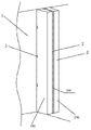
Fig. 1 is that the side adopts U-shaped location fastener to fix and the schematic diagram of the internal partition wall that end face employing corner brace is fixed;
Fig. 2 is the schematic diagram that side and end face all adopt the fixing internal partition wall of U-shaped location fastener;
Fig. 3 is the stereogram of doubling plate interior wall;
Fig. 4 is the structural representation of the stereogram of doubling plate interior wall;
Fig. 5 is the stereogram of U-shaped location fastener;
Fig. 6 is with the fixing schematic diagram of wallboard of voussoir;
Fig. 7 is for arranging the schematic diagram of fiber guipure in adjacent two wallboard junctions;
Fig. 8 is the schematic diagram of Flat gasket;
Fig. 9 is the schematic diagram of angle cushion block;
Figure 10 is for arranging the schematic diagram of Flat gasket between beam slab and wallboard;
Figure 11 is for arranging the schematic diagram of angle cushion block between beam slab and wallboard.
The specific embodiment
Below in conjunction with description of drawings and the specific embodiment the utility model is further described:
Shown in Fig. 1 to 11, the two wallboard internal partition walls of a kind of fissure of displacement, it comprises first surface body of wall 100 and the second face wall body 200 that separates, form hollow layer 300 between them, one side of described first surface body of wall 100, end face, underrun mortar are separately fixed on structure wall column 1, beam slab 4, the floor 6, first surface body of wall 100 is formed by connecting by mortar in turn by polylith wallboard 2, forms the first junction 101 between the wallboard 2 of first surface body of wall 100; One side of described the second face wall body 200, end face, underrun mortar are separately fixed on structure wall column 1, beam slab 4, the floor 6, the second face wall body 200 also is formed by connecting by mortar in turn by polylith wallboard 2, form the second junction 201 between the wallboard of the second face wall body 200, all second junctions 201 intermesh with all first junctions 101; First surface body of wall 100 and the second face wall body 200 outer ends seal by mortar so that the second face wall body 200 and first surface body of wall 100 form the fissure of displacement wall of hollows.
Such as Fig. 1-3, at first surface body of wall 100 and structure wall 1, and between the second face wall body 200 and structure wall 1, all distinguish a plurality of U-shapeds for positioning wall of vertical installation and locate fasteners 3, this U-shaped location fastener 3 comprises brace 31, be connected with respectively the first perpendicular card 32, the second card 33 in the both sides of brace 31, be formed for placing the mounting groove 34 of wallboard 2 between the inner surface of described brace 31 and the first card 32, the second card 33, the thickness of the width of this mounting groove 34 and wallboard 2 is suitable.
Described U-shaped location fastener 3 by the two ends of a rectangle steel disc in the same way one side bending 90 degree of rectangle steel disc form.
Referring to Fig. 7, be provided with positive tenon 21 in a side of described wallboard 2, the another side is provided with cloudy tenon 22; The positive tenon 21 in the left side of first surface body of wall 100 and the second face wall body 200 withstands on the inner surface of described brace 31.The short slot of front and rear surfaces is combined into respectively front vertical groove and rear vertical groove after being respectively equipped with short slot 23, two wallboards and connecting near the place of side on described wallboard 2 forward and backward surfaces.Paste by glass guipure 8 with mortar at front vertical groove and rear vertical groove.
Referring to Fig. 8-11, evenly be fixed with for the top rubber cushion piece 7 of top to the beam slab 4 at the end face of described wallboard 2.
Referring to Fig. 8,10, described wallboard 2 is solid wall plate, described top rubber cushion piece 7 is Flat gasket 70, Flat gasket 70 comprises cushion block body 72, be provided with the connection convex tendon 73 of a plurality of tops to the beam slab 4 in described cushion block body 72 upper surfaces, when described cushion block body 72 is provided with a plurality of grouting, can make slurry enter the through hole 74 of cushion block body 72 inside, before wallboard is holded up, with mortar Flat gasket 70 bottoms are bonded on the wallboard.
Referring to Fig. 9,11, described wallboard 2 is hollow wall panel, in hollow wall panel, be provided with a plurality of core holes 20 that separate, described top rubber cushion piece 7 is angle cushion block 71, angle cushion block 71 comprises cushion block body 72, be provided with a plurality of tops in described cushion block body 72 upper surfaces and connect convex tendon 73 to beam slab 4, when described cushion block body 72 is provided with a plurality of grouting, can make slurry enter the through hole 74 of cushion block body 72 inside, be provided with the snap fit 75 that can snap onto respectively in two adjacent core holes 20 in both sides, described cushion block body 72 lower surface.Wallboard 2 is hollow wall panel, during installation, puts into foam rods in the core hole of the upper end of wallboard, avoids when Reinforcing wall slab stitches, and mortar bleeds in the core hole.
In order further to strengthen the constant intensity of body of wall, when being installed, reinforces on the top of wallboard wallboard.
Referring to Fig. 1, a kind of Scheme of Strengthening is to adopt corner brace 9, and described corner brace 9 includes the first connecting portion 91 and the second connecting portion 92, the first connecting portions 91 and the second connecting portion 92 and is interconnected to L-type.After squeezing into voussoir 5 between the bottom surface of wallboard and the floor 6, on the first connecting portion 91 of corner brace 9, side that the second connecting portion 92 is attached to respectively this piece wallboard, beam slab; Then with ail gun the first connecting portion 91, the second connecting portion 92 are separately fixed on the side, beam slab of this piece wallboard, so that this piece wallboard is securely fixed on the beam slab.
Referring to Fig. 2, another kind of Scheme of Strengthening is to adopt described U-shaped location fastener 3, with a U-shaped location fastener 3 two blocks of wallboards is fixed on the beam slab 4 between two blocks of adjacent wallboards.Concrete mounting method is as follows: before squeezing into voussoir 5 between this piece wallboard bottom surface and the floor 6, described U-shaped location fastener 3 is installed in the lower wallboard junction that beam slab 4 is positioned at this piece wallboard and preparation installation in position according to the wall line, during installation, the surface that the external surface of brace 31 is fitted in beam slab 4 is fixed on brace 31 on the beam slab 4 with nail, so that the first card 32 of U-shaped location fastener 3, the second card 33 is perpendicular to the ground, the end face of wallboard is aimed in mounting groove 34 parts of the U-shaped location fastener 3 that snaps onto the top after squeezing into voussoir 5, so that the first card 32 of U-shaped location fastener 3, the second card 33 is stuck on the wallboard front surface and wallboard rear surface of wallboard, and the top end face of this sample block wallboard just is fixed on the beam slab 4 by U-shaped location fastener 3.Another part that mounting groove 34 reserves is used for installing next piece wallboard.So continuous installation just can be fixed on the beam slab 4 by a U-shaped location fastener 3 between two blocks of adjacent wallboards.Adopt wallboard top end face U-shaped location fastener 3 to fix and further to realize calibration to wallboard.
The mounting process of this pair of wallboard internal partition wall, it may further comprise the steps:
A, location unwrapping wire: emit the first surface into pre-installation, the wall line of the second face wall body location on construction ground, the wall line comprises above-ground route and day upper thread;
B, installation first surface body of wall 100: after first the wallboard 2 of side and end face applying mortar being holded up its side is bonded on the structure wall column 1, then squeeze between first wallboard bottom surface and floor 6 and make the wallboard end face upwards hold out against voussoir 5 on the beam slab 4, mortar is filled respectively in a plurality of spaces that form between floor and wallboard bottom; Then according to wallboard 2 mounting meanss other wallboard is installed successively in the another side of wallboard 2, is withdrawed from last the fixedly voussoir 5 rear mortars of filling in the voussoir hole of wallboard 2, finish the installation of first surface body of wall 100; Form the first junction 101 between the wallboard of first surface body of wall 100;
C, installation the second face wall body 200, according to first surface body of wall 100 mounting meanss the second face wall body 200 is installed on first surface body of wall 100 sides, form hollow layer 300 between the second face wall body 200 and the first surface body of wall 100, form the second junction 201 between the wallboard of the second face wall body 200, all second junctions 201 intermesh with all first junctions 101;
D, shutoff two bodies of wall use mortar 400 with first surface body of wall 100 and the 200 outer end shutoff of the second face wall body, so that two wall connectings become the hollow wall of a stifled fissure of displacement.
The surface that when U-shaped location fastener 3 is installed the external surface of brace 31 is fitted in structure wall column 1 is fixed on brace 31 on the structure wall column 1 with nail, so that the first card 32, second card 33 of U-shaped location fastener 3 are all vertical with the surface of ground, structure wall column 1; The U-shaped that is equipped with more than at least 2 along the vertical direction interval on structure wall column 1 is located fastener 3, mounting groove 34 in the vertical directions of all U-shaped location fasteners 3 are arranged in a row, then first block of wallboard holded up and its first side is aimed in the mounting groove 34 that snaps onto all U-shapeds location fasteners 3, so that on the first card 32 of U-shaped location fastener 3, wallboard front surface and wallboard rear surface that the second card 33 is stuck in first block of wallboard.
Claims (8)
1. two wallboard internal partition walls of the fissure of displacement, it is characterized in that comprising the first surface body of wall (100) and the second face wall body (200) that separate, form hollow layer (300) between them, one side of described first surface body of wall (100), end face, underrun mortar are separately fixed on structure wall column (1), beam slab (4), floor (6), first surface body of wall (100) is formed by connecting by mortar in turn by polylith wallboard (2), forms the first junction (101) between the wallboard of first surface body of wall (100); One side of described the second face wall body (200), end face, underrun mortar are separately fixed on structure wall column (1), beam slab (4), floor (6), the second face wall body (200) also is formed by connecting by mortar in turn by polylith wallboard (2), form the second junction (201) between the wallboard of the second face wall body (200), all second junctions (201) intermesh with all first junctions (101); So that the second face wall body (200) and first surface body of wall (100) form the fissure of displacement wall of hollow, described wallboard is to make concrete aggregate with light ceramic by the mortar sealing for first surface body of wall (100) and the second face wall body (200) outer end.
2. two wallboard internal partition walls of a kind of fissure of displacement according to claim 1, it is characterized in that: at first surface body of wall (100) and structure wall (1), and between the second face wall body (200) and structure wall (1), all distinguish a plurality of U-shapeds for positioning wall of vertical installation and locate fasteners (3), this U-shaped location fastener (3) comprises brace (31), be connected with respectively perpendicular the first card (32) in the both sides of brace (31), the second card (33), the inner surface of described brace (31) and the first card (32), be formed for placing the mounting groove (34) of wallboard (2) between the second card (33), the thickness of the width of this mounting groove (34) and wallboard (2) is suitable.
3. the two wallboard internal partition walls of a kind of fissure of displacement according to claim 2 is characterized in that: a row also is installed on the wallboard top and between beam slab (4) is used for the fixedly described U-shaped location fastener (3) on wallboard top.
4. it is characterized in that according to claim 2 or the two wallboard internal partition walls of 3 described a kind of fissure of displacement: described U-shaped location fastener (3) by the two ends of a rectangle steel disc in the same way one side bending 90 degree of rectangle steel disc form.
5. two wallboard internal partition walls of a kind of fissure of displacement according to claim 2, it is characterized in that: be fixed with corner brace (9) on the wallboard top and between beam slab (4), corner brace (9) comprises the first connecting portion (91) and the second connecting portion (92) that connects into L-type, in the time of fixedly the first connecting portion (91), the second connecting portion (92) is separately fixed on the side, beam slab of this piece wallboard.
6. two wallboard internal partition walls of a kind of fissure of displacement according to claim 1 is characterized in that: evenly be fixed with for the top rubber cushion piece (7) of top to the beam slab (4) at the end face of described wallboard (2).
7. two wallboard internal partition walls of a kind of fissure of displacement according to claim 6, it is characterized in that: described wallboard (2) is solid wall plate, described top rubber cushion piece (7) is Flat gasket (70), Flat gasket (70) comprises cushion block body (72), be provided with the connection convex tendon (73) of a plurality of tops to the beam slab (4) in described cushion block body (72) upper surface, when described cushion block body (72) is provided with a plurality of grouting, can make slurry enter the inner through hole (74) of cushion block body (72).
8. two wallboard internal partition walls of a kind of fissure of displacement according to claim 6, it is characterized in that: described wallboard (2) is hollow wall panel, in hollow wall panel, be provided with a plurality of core holes (20) that separate, described top rubber cushion piece (7) is angle cushion block (71), angle cushion block (71) comprises cushion block body (72), be provided with a plurality of tops in described cushion block body (72) upper surface and connect convex tendon (73) to beam slab (4), when described cushion block body (72) is provided with a plurality of grouting, can make slurry enter the inner through hole (74) of cushion block body (72), be provided with the snap fit (75) that can snap onto respectively in adjacent two core holes (20) in described cushion block body (72) both sides, lower surface.
Priority Applications (1)
| Application Number | Priority Date | Filing Date | Title |
|---|---|---|---|
| CN 201220369496 CN202831299U (en) | 2012-07-27 | 2012-07-27 | Double-wallboard staggered joint internal partition |
Applications Claiming Priority (1)
| Application Number | Priority Date | Filing Date | Title |
|---|---|---|---|
| CN 201220369496 CN202831299U (en) | 2012-07-27 | 2012-07-27 | Double-wallboard staggered joint internal partition |
Publications (1)
| Publication Number | Publication Date |
|---|---|
| CN202831299U true CN202831299U (en) | 2013-03-27 |
Family
ID=47943043
Family Applications (1)
| Application Number | Title | Priority Date | Filing Date |
|---|---|---|---|
| CN 201220369496 Expired - Lifetime CN202831299U (en) | 2012-07-27 | 2012-07-27 | Double-wallboard staggered joint internal partition |
Country Status (1)
| Country | Link |
|---|---|
| CN (1) | CN202831299U (en) |
Cited By (2)
| Publication number | Priority date | Publication date | Assignee | Title |
|---|---|---|---|---|
| CN102777040A (en) * | 2012-07-27 | 2012-11-14 | 中山建华墙体材料有限公司 | Installation process of stagger-joint dual-wallboard inner partition wall and dual-wallboard inner partition |
| CN106894547A (en) * | 2017-04-05 | 2017-06-27 | 潘旭鹏 | A kind of lightweight sectioned wall and its installation method |
-
2012
- 2012-07-27 CN CN 201220369496 patent/CN202831299U/en not_active Expired - Lifetime
Cited By (2)
| Publication number | Priority date | Publication date | Assignee | Title |
|---|---|---|---|---|
| CN102777040A (en) * | 2012-07-27 | 2012-11-14 | 中山建华墙体材料有限公司 | Installation process of stagger-joint dual-wallboard inner partition wall and dual-wallboard inner partition |
| CN106894547A (en) * | 2017-04-05 | 2017-06-27 | 潘旭鹏 | A kind of lightweight sectioned wall and its installation method |
Similar Documents
| Publication | Publication Date | Title |
|---|---|---|
| CN102777040A (en) | Installation process of stagger-joint dual-wallboard inner partition wall and dual-wallboard inner partition | |
| CN105863155A (en) | Heat insulation and energy storage type RPC prefabricated wall panel system | |
| CN102400561B (en) | Installation method of paper honeycomb composite wall body | |
| CN206053024U (en) | Integrated house wall structure | |
| CN103572874A (en) | Method for constructing reinforced concrete composite floor slab of steel frame house | |
| CN111005442A (en) | SIP plate type structure prefabricated house building combined with light steel and construction method thereof | |
| CN202831299U (en) | Double-wallboard staggered joint internal partition | |
| CN206957099U (en) | A kind of insulation and decoration acoustic wall board | |
| CN211341412U (en) | Assembled partition board component | |
| CN103452209B (en) | Double-layer composite slat cast-in-situ internal partition wall structure | |
| CN103485538A (en) | Construction method of energy-saving insulation waterproof wood-trussed roof system | |
| CN207672806U (en) | A kind of hollow assembled board wall system | |
| CN203129365U (en) | Hollow sound proof wall | |
| CN2931620Y (en) | Assembly wall | |
| CN213204665U (en) | Shale sintered composite board for fabricated building | |
| CN204151985U (en) | Sandwich wall Self-thermal-insulation System | |
| CN209397858U (en) | Prefabricated foamed ceramic frame exterior wall cladding | |
| CN202064480U (en) | Outer separating wall built with lightweight concrete separating plates | |
| CN111663710A (en) | Method for manufacturing shale sintered composite board for assembly type building | |
| CN201236416Y (en) | Prefabricated component for denizen house and prefabricated component house | |
| CN201099934Y (en) | Energy-saving quake-proof lightweight keel-free slot-free grouting -type architecture combined ribbon board | |
| CN110397189A (en) | A kind of light aggregate concrete combined type load-bearing external wall structure | |
| CN211499446U (en) | Transversely assembled wallboard | |
| CN220620714U (en) | Prefabricated constructional column of light partition board | |
| CN107829509A (en) | A kind of ALC neotectonics building structure |
Legal Events
| Date | Code | Title | Description |
|---|---|---|---|
| C14 | Grant of patent or utility model | ||
| GR01 | Patent grant | ||
| CX01 | Expiry of patent term | ||
| CX01 | Expiry of patent term |
Granted publication date: 20130327 |