CN202831203U - Assembly type concrete frame-shear wall split assembling structure and fabricative structure - Google Patents
Assembly type concrete frame-shear wall split assembling structure and fabricative structure Download PDFInfo
- Publication number
- CN202831203U CN202831203U CN 201220520805 CN201220520805U CN202831203U CN 202831203 U CN202831203 U CN 202831203U CN 201220520805 CN201220520805 CN 201220520805 CN 201220520805 U CN201220520805 U CN 201220520805U CN 202831203 U CN202831203 U CN 202831203U
- Authority
- CN
- China
- Prior art keywords
- shear wall
- precast
- wall
- sleeve
- prefabricated
- Prior art date
- Legal status (The legal status is an assumption and is not a legal conclusion. Google has not performed a legal analysis and makes no representation as to the accuracy of the status listed.)
- Withdrawn - After Issue
Links
Images


Landscapes
- Load-Bearing And Curtain Walls (AREA)
Abstract
The utility model relates to the field of concrete structure, and particularly relates to an sssembly type concrete frame-shear wall split assembling structure and a fabricative structure. The sssembly type concrete frame-shear wall split assembling structure comprises prefabricated columns, prefabricated beams, prefabricated shear walls and cast-in-place nodes. Sleeves are embedded at lower ends of the prefabricated columns, mutually combined with rebar protruding sections stretching out from upper ends of lower layer columns in an embedded mode, and connected with the lower layer columns into a whole through pouring of sand pulp. Longitudinal rebar of the prefabricated beams stretches into core areas of the nodes and are anchored or the longitudinal rebar is in mechanical connection with corresponding side beam ribs. A cast-in-place belt is arranged between the prefabricated columns and the prefabricated shear walls for connection of column wall embedded ribs. Lower end embedded rebar sleeves of the prefabricated shear walls are mutually combined with rebar protruding sections stretching out from lower layer walls in an embedded mode, and connected with lower layer walls into a whole through the pouring of the sand pulp. Vertical rebar of upper and lower layer shear walls is communicated and connected by the fact that upper ends of the prefabricated shear walls and the prefabricated beams pour the sand pulp to through holes and the sleeves, so the problem that the vertical rebar of the shear walls is hard to be continuous due to separation and cutting of the prefabricated beams is solved.
Description
[technical field]
The utility model relates to the prefabricated concrete structure field, be specially the fractionation assembly unit system of a kind of fabricated assembly overall that is consisted of by prefabricated post, precast beam and precast shear wall (hereinafter to be referred as assembling) concrete frame-shear wall structure, member connects structure, by this fractionation assembly unit system and the works that is connected the structure construction, and the assembly unit method of attachment.
[background technology]
The prior art of prefabricated concrete structure mainly is pure frame structure and shear wall structure, and the assembly concrete frame shear wall structure that is made of prefabricated post, precast beam and precast shear wall there is not yet the work literary composition.Compare with pure frame structure or shear wall structure, because concrete frame-shear wall structure is the combination of wire rod and plane materiel, particularly shear wall is cut off by beam and column, causes the steel bar stress assembling difficulty that continues large, has no rationally effectively solution.Up to the present, concrete frame-shear wall structure mainly is to build by complete cast-in-place engineering method.The conventional way of assembling frame structure is that beam and column is prefabricated, and node is cast-in-place, is characterized in that the interspersed connection that crosses of reinforcing bar of all directions beam and column is anchored in joint cores, and the node construction difficulty is larger, but structural integrity is good, can reach to be equal to cast-in-place structural.The current practice of fabricated shear wall structure is, the wall vertical reinforcement adopts docking sleeve or preformed hole reinforcing bar slurry anchor overlap joint up and down, and left and right sides wall horizontal reinforcement adopts cast-in-place band overlap joint, its subject matter is that vertical reinforcement is generally double-sided ribs, its radical is too much, and lap length is longer, is not easy to construction.
[utility model content]
The purpose of this utility model is to provide a kind of assembling fractionation assembly unit syndeton of concrete frame-shear wall structure to be connected construction method with assembly unit, core content is to adopt cast-in-place node with when reaching simplification structure manufacture and assembly unit difficulty, propose 1. to get rid of muscle on the shear wall, 2. independent joint bar, 3. the connected mode of pre-these three kinds of shear wall vertical reinforcements of doweling in the beam solves because precast beam cuts off and makes the shear wall vertical reinforcement be difficult to continuous key issue.
The technical solution of the utility model:
A kind of assembly concrete Frame-Shear Wall splits splicing structure, and this structure is that the structure that prefabricated post, precast beam, precast shear wall and cast-in-place node consist of splits the assembly unit system;
The lower end embedded bar sleeve of prefabricated post, mutually chimeric with the reinforcing bar nose section that the lower floor post is stretched up, by in sleeve and the horizontal joint that links to each other, annotating mortar, be connected to integral body with the lower floor post;
The lower end embedded bar sleeve of precast shear wall, mutually chimeric with the reinforcing bar nose section that the lower floor wall is stretched up, by perfusion mortar in sleeve and the horizontal joint that links to each other, be connected to integral body with the lower floor shear wall;
Cast-in-place band is set between prefabricated post and the precast shear wall, and in cast-in-place band to making prefabricated post side embedded bar and shear wall end face embedded bar carry out level connection joint, make prefabricated post and shear wall be connected to integral body by cast-in-place concrete;
The upper end of prefabricated post is outstanding straight reinforcing bar, runs through cast-in-place node and protrudes from the floor face.
Described assembly concrete Frame-Shear Wall splits splicing structure, and the upper end of precast shear wall is outstanding straight reinforcing bar, reserves through hole in the precast beam; The outstanding straight reinforcing bar of precast shear wall upper end runs through precast beam reservation through hole and protrudes from the floor face, reserves perfusion mortar in the horizontal joint between through hole and shear wall upper end and the beam, makes shear wall and beam consolidation be integral body.
Described assembly concrete Frame-Shear Wall splits splicing structure, the upper end embedded bar sleeve of precast shear wall, reserve through hole in the precast beam, in addition standby independently up and down the wall dowel as joint bar, joint bar runs through precast beam from top to bottom reserves through hole, and in the pre-buried reinforced bar sleeve in insertion precast shear wall upper end, sleeve, shear wall upper end with at the bottom of the beam between horizontal joint and reserve perfusion mortar in the through hole, making shear wall and beam consolidation is integral body.
Described assembly concrete Frame-Shear Wall splits splicing structure, the upper end embedded bar sleeve of precast shear wall, pre-buried up and down wall dowel in the precast beam, precast beam is installed from top to bottom, the lower end of pre-buried up and down wall dowel is inserted in the pre-buried reinforced bar sleeve in precast shear wall upper end, perfusion mortar in the horizontal joint between at the bottom of sleeve and shear wall upper end and the beam makes shear wall and beam be connected to integral body.
Described assembly concrete Frame-Shear Wall splits splicing structure, and the fractionation that arranges in the optional position of described shear wall horizontal direction between shear wall and the adjacent post connects and the fractionation connection of being connected shear wall self.
Described assembly concrete Frame-Shear Wall splits splicing structure, and precast beam adopts the precast beam of superimposed mode, and perhaps precast beam adopts the precast beam of full prefabrication system.
Described assembly concrete Frame-Shear Wall splits splicing structure, and the docking mode of sleeve grouting adopts preformed hole reinforcing bar slurry anchor overlapping mode to replace.
Described assembly concrete Frame-Shear Wall splits splicing structure, and this structure perhaps has the in length and breadth frame shear wall structure of axle two direction shear walls as having the single span shear wall, connecting the frame shear wall structure of striding shear wall.
In the utility model, can use the frame shear wall structure thing of the fractionation splicing structure construction of above-mentioned any one described assembly concrete Frame-Shear Wall.
Above-mentioned assembly concrete Frame-Shear Wall splits the assembly unit method of attachment of splicing structure, in every floor construction,
The first step, hoisting prefabricated post, the reinforcing bar nose section that lower end embedded bar sleeve and lower floor's post of left and right sides prefabricated post are stretched up is mutually chimeric, locate backward sleeve and the interior mortar of annotating of the horizontal joint that links to each other;
Second step, hoisting prefabricated shear wall, the reinforcing bar nose section that lower end embedded bar sleeve and lower floor's wall of precast shear wall are stretched up is mutually chimeric, locate backward sleeve and the interior perfusion mortar of the horizontal joint that links to each other;
The 3rd step, post side embedded bar nose section and shear wall end face embedded bar nose section are carried out level overlap, configure simultaneously vertical reinforcement, then at cast-in-place band portion formwork and fluid concrete;
The 4th step, hoisting prefabricated beam, the outstanding straight reinforcing bar in precast shear wall upper end is run through reserve through hole in the precast beam, or the wall dowel passes in the pre-buried sleeve in precast beam through hole insertion precast shear wall upper end from top to bottom up and down, or the interior pre-doweling of precast beam is inserted in the pre-buried sleeve in precast shear wall upper end from top to bottom; After precast beam install is in place, to horizontal joint and reserve through hole and sleeve in perfusion mortar;
The 5th step, beam column node core area formwork, cast-in-situ floor formwork or superimposed sheet is installed and is configured upper reinforcement;
The 6th step, build node concrete, build the overlapping layers concrete, finish this layer construction;
Carry out the last layer construction, repeat above six steps.
Effect of the present utility model:
1, the fractionation splicing structure system that the utility model proposes and member method of attachment, see on the whole to have following characteristics: it is reasonable that 1. each member splits the position, is convenient to structure manufacture and transportation; 2. member is generally symmetrical, and weight is reasonable, is convenient to lifting and installs; 3. all members are from top to bottom and install, and are convenient to lifting and install; 4. the vertical reinforcement joint adopts single reinforced bar sleeve grouting docking, and joint is reliable; 5. the shear wall vertical reinforcement is that the large spacing diameter steel bar of a row is configured on the wall center line with calculating the vertical reinforcement area that needs concentrated in by the two-sided distribution bar of minimum structure requirement configuration.Like this, namely satisfy the requirement of standard structure, bar splice is few again.Although amount of reinforcement slightly increases, sleeve is few, and cost is relatively low, goes back constructability; 6. cast-in-place bandwidth is little between the post wall, and the situ wet operation is few, and assembly rate is high.
2, core content of the present utility model is the method for attachment of precast shear wall vertical reinforcement (core muscle), and three kinds of methods in the utility model have characteristics separately, can be according to the physical condition reasonable selection.When consisting of the assembly concrete frame shear wall structure by prefabricated post, precast beam and precast shear wall, fractionation how to carry out post be connected, the fractionation of beam be connected, the fractionation of shear wall and adjacent post be connected, the fractionation of shear wall and adjacent beams be connected and the connection of reinforcing bar between the levels shear wall.Rationally effectively split assembly unit system and member connected mode by adopting, reduce to greatest extent the wet trades such as cast-in-place concrete, improve the assemblingization degree, the reduction of erection time, make things convenient for simultaneously structure manufacture and the globality that guarantees fabricated construction.
3, the utility model structural system is made of prefabricated post, precast beam, precast shear wall and cast-in-place node, prefabricated post lower end embedded sleeve barrel, mutually chimeric with the reinforcing bar nose section that lower floor post upper end is stretched, connect as one by perfusion mortar and lower floor's post, the precast beam longitudinal reinforcement stretch in the joint cores anchoring or with the curb girder muscle is carried out mechanical type is connected, cast-in-place band is set between prefabricated post and the precast shear wall carries out the connection of post wall embedded ribs.The reinforcing bar nose section that precast shear wall lower end embedded bar sleeve and lower floor's wall are stretched up is mutually chimeric, connects as one by perfusion mortar and lower floor's wall.Reserve corresponding linkings of vertical through hole in the outstanding reinforcing bar in precast shear wall upper end and the precast beam, perhaps, the in advance corresponding linking of insertion bar dowel behind doweling or the interior reservation of the precast beam through hole in precast shear wall upper end embedded bar sleeve and the precast beam.Thereby, by to through hole and sleeve perfusion mortar, realize that the perforation of levels shear wall vertical reinforcement connects.
[description of drawings]
Fig. 1 (a)-Fig. 1 (d): the utility model the first assembly concrete frame shear wall structure splits assembly unit and connects constructional drawing (1. reserve through hole in the precast beam, be inserted in the outstanding reinforcing bar mode in dry wall top).Wherein, the facade main view of Fig. 1 (a) for splitting; Fig. 1 (b) is the facade main view of assembly unit; Fig. 1 (c) is II among Fig. 1 (a)-II sectional drawing; Fig. 1 (d) is I among Fig. 1 (a)-I sectional drawing.
Fig. 2 (a)-Fig. 2 (d): it is flat, vertical that the utility model the second assembly concrete frame shear wall structure fractionation assembly unit connects structure, sectional drawing (2. interior through hole, the beam rear insertion bar dowel mode in place reserved of precast beam).Wherein, the facade main view of Fig. 2 (a) for splitting; Fig. 2 (b) is the facade main view of assembly unit; Fig. 2 (c) is II among Fig. 2 (a)-II sectional drawing; Fig. 2 (d) is I among Fig. 2 (a)-I sectional drawing.
Fig. 3 (a)-Fig. 3 (d): it is flat, vertical that the third assembly concrete frame shear wall structure fractionation assembly unit of the utility model connects structure, sectional drawing (the 3. interior pre-doweling mode of precast beam).Wherein, the facade main view of Fig. 3 (a) for splitting; Fig. 3 (b) is the facade main view of assembly unit; Fig. 3 (c) is that II is foretold the II sectional drawing among Fig. 3 (a); Fig. 3 (d) is I among Fig. 3 (a)-I sectional drawing.
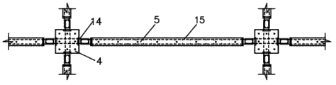
Among the figure, 1 precast beam (superposed beam); 2 reserve through hole; 3 groove shear key I; 4 prefabricated post; 5 precast shear walls; Wall dowel about in the of 6; 7 cast-in-place band joint bars; 8 groove shear key II; 9 cast-in-situ concretes; 10 grouting; 11 on-the-spot arrangements of reinforcement; 12 cast-in-place bands; 13 cast-in-place nodes; 14 groove shear key III; 15 two-sided distribution bars within the walls; 16 sleeve I; Wall dowel (joint bar) about in the of 17; The grouting of 18 horizontal joints or seat slurry; 19 sleeve II; Wall dowel (pre-buried) about in the of 21; The U-shaped dowel of 22 walls; The U-shaped dowel of 23 posts.
[specific embodiment]
The utility model assembly concrete Frame-Shear Wall splits splicing structure and assembly unit method of attachment, and is specific as follows:
(1) adopts by prefabricated or partial precast post (hereinafter to be referred as prefabricated post), prefabricated or partial precast beam (hereinafter to be referred as precast beam) and fractionation assembly unit system prefabricated or partial precast shear wall (hereinafter to be referred as dry wall) formation structure.Wherein the node of column and beam core space adopts cast-in-place mode, to guarantee the globality of post beam, is convenient to simultaneously element precast.For the interconnecting of vertical reinforcement between the levels shear wall in implementation framework-shear wall structure, be provided with in the precast beam and intert reservation through hole or the pre-doweling of body of wall vertical reinforcement.Prefabricated post is connected the connection of vertical reinforcement and is all adopted the docking sleeve mode with precast shear wall.
(2) the reservation through hole that is used for interspersed shear wall vertical reinforcement in the precast beam can adopt the metal bellows moulding, also can adopt the moulding of plastics QC.Metal bellows should adopt two rib bellowss, and its rib Gao Yi is more than 1mm.The pore-forming internal diameter is decided according to wearing bar diameter d, generally should be taken as 1.2d~3.0d.
(3) split on the wall limit between precast shear wall and the adjacent post.Between connection adopt cast-in-place band mode, U-shaped dowel be set carry out the level overlap joint from precast shear wall and adjacent post are outstanding separately.It is overlapped mutually form degree of lip-rounding closed confinement space, form sleeper thereby insert from top to bottom the bight vertical reinforcement at four interior angle places of this closed space.In addition, with relative prefabricated post side concrete groove shear key should be set respectively at the shear wall end face.By cast-in-place band portion formwork and poured in place concrete, make shear wall and adjacent post form integral body.This connected mode can realize following working mechanism: on the one hand U-shaped dowel overlap joint can significantly reduce the lap length of reinforcing bar, further strengthens again the anchoring of U-shaped dowel by Xiao's bolt effect of joint bar.This reinforcement manner can form sleeper on the other hand, strengthens the binding effect to shear wall, thereby improves bearing capacity and the ductility of shear wall.Concrete groove shear key is set, to increase interface shearing strength, reduces shearing slip, strengthen the co-operation of shear wall and peripheral frame.
(4) prefabricated post splits at capital face and basal surface position.Sleeve grouting docking mode is adopted in the connection of the vertical reinforcement of levels prefabricated post, with the reliability that guarantees to connect.Be that the prefabricated post lower end is buried sleeve underground, the outstanding straight reinforcing bar of cast-in-place joint cores that passes through in upper end.After lower floor's beam column node core area and the hardening of concrete of floor in-situ layer, lift this layer post installation in position, in sleeve and prefabricated post lower end horizontal joint, pour into high-strength mortar, this layer post and lower floor's post folder node are become one, and be connected to integral body by cast-in-place node and precast beam.
(5) split at wall end face and basal surface position between precast shear wall and the upper underbeam.Except single or double level and vertical distribution reinforcement are set, will calculate required vertical applied force reinforcing bar centralized arrangement in wall core (being called for short shear wall core muscle) in the precast shear wall, and be connected with levels shear wall core muscle.Sleeve grouting docking mode is adopted in the vertical connection of shear wall core muscle, its lower end embedded sleeve barrel, the core muscle tabling of stretching up with the lower floor shear wall, behind the installation in position, the perfusion high-strength mortar makes this layer body of wall and lower floor body of wall press from both sides beam to become one in sleeve and the horizontal joint that links to each other.There are following three kinds of ways the upper end of precast shear wall:
(1) the outstanding straight reinforcing bar (up and down wall dowel) in precast shear wall upper end.When the top precast beam was installed, the vertical reinforcement that the precast shear wall upper end is given prominence to ran through the through hole of reserving in the precast beam and protrudes from more than the top surface of the beam (being floor face), between shear wall upper end and the soffit horizontal joint was set.After precast beam install is in place, reserves in the precast beam in through hole and the horizontal joint that links to each other and pour into high-strength mortar, make that precast shear wall and precast beam are fixed to be integral body.
(2) precast shear wall upper end embedded sleeve barrel.When the top precast beam is installed, make the interior reservation of beam through hole roughly consistent with the position, hole of its lower shear wall upper end embedded sleeve barrel, then wall dowel (abbreviation joint bar) passes in the pre-buried sleeve in through hole insertion precast shear wall upper end from top to bottom up and down, in sleeve, between precast beam and the lower wall in the horizontal joint and reserve in the through hole in the precast beam and pour into high-strength mortar, make that precast shear wall and precast beam are fixed to be integral body.
(3) precast shear wall upper end embedded sleeve barrel, pre-buried up and down wall dowel (joint bar) in the precast beam.When the top precast beam is installed, the interior pre-doweling of beam is inserted in the pre-buried sleeve in precast shear wall upper end from top to bottom, after precast beam install is in place, in sleeve and between precast beam and the lower wall, pour into high-strength mortar in the horizontal joint, make precast shear wall and precast beam fixed for whole.
(6) be assembling fractionation assembly unit system and the connection structure in the frame shear wall structure plane more than.Can adopt above-mentioned form equally with the connection of plane external member (be the vertical direction member, comprise wall, beam, floor etc.).
(7) job practices of the utility model structure fractionation assembly unit system is: from every layer floor face, 1. prefabricated post is installed.Make prefabricated post bottom embedded sleeve barrel and lower floor's post bar splice mutually chimeric, in place after, the precast shear wall between erection column of column bottom sleeve and horizontal joint grouting connection → 2..Lift first body of wall to the outside, post plane and the bar splice that keeps a little higher than lower floor wall to stretch out, confirming that post stretches out the height that U-shaped dowel and wall stretch out U-shaped dowel mutually noninterfere body of wall is moved horizontally to intercolumniation, then descending makes shear wall bottom embedded sleeve barrel and lower floor's wall bar splice mutually chimeric.After in place, U-shaped dowel interior angle place's vertical reinforcement and colligation connect → are 3. inserted in the grouting of shear wall bottom sleeves and horizontal joint from top to bottom, finish cast-in-place band arrangement of reinforcement, cast-in-place band both sides formwork, concreting → 4. install precast beam.Hoisting prefabricated beam from top to bottom, the outstanding straight reinforcing bar in precast shear wall upper end is run through reserve in the precast beam through hole/or up and down wall dowel (joint bar) pass from top to bottom the precast beam through hole and insert in the pre-buried sleeve in precast shear wall upper end/or make that pre-doweling inserts in the pre-buried sleeve in precast shear wall upper end from top to bottom in the precast beam.After precast beam install is in place, to horizontal joint with reserve perfusion high-strength mortar in the through hole (and sleeve) → 5. bean column node and floor slab construction.Cast-in-place beam column node core area, cast-in-situ floor or laminated floor slab top configuration reinforcement are also built the overlapping layers concrete.
Fig. 1 (a)-(d) reserves through hole 2 in the precast beam, be inserted in the outstanding reinforcing bar mode in dry wall 5 tops.This assembly concrete Frame-Shear Wall splits splicing structure and mainly comprises: precast beam (superposed beam) 1, reserve through hole 2, groove shear key I 3, prefabricated post 4, precast shear wall 5, up and down wall dowel 6, cast-in-place band joint bar 7, groove shear key II 8, cast-in-situ concrete 9, grouting 10, on-the-spot arrangement of reinforcement 11, cast-in-placely be with 12, cast-in-place node 13, groove shear key III 14, within the walls two-sided distribution bar 15, sleeve I 16, the U-shaped dowel 22 of wall, the U-shaped dowel 23 of post etc., concrete structure is as follows:
Be provided with precast shear wall 5 between the prefabricated post 4, precast shear wall 5 is with 12 to be connected with prefabricated post 4 by cast-in-place, 4 liang of side-prominent U-shaped dowels 23 of post that arrange of prefabricated post, precast shear wall 5 outstanding the arrange wall U-shaped dowels 22 corresponding with prefabricated post 4, the U-shaped dowel 22 of wall and the U-shaped dowel 23 levels overlap joint of post, it is overlapped mutually form degree of lip-rounding closed confinement space, and plug from top to bottom cast-in-place band joint bar 7 at four interior angle places, this closed confinement space, be respectively equipped with groove shear key II 8 and groove shear key III 14 at precast shear wall 5 and prefabricated post 4 opposite faces, cast-in-placely be with 12 to be cast in precast shear wall 5 and prefabricated post 4 junctions.
Shown in Fig. 1 (a)-Fig. 1 (c), after precast beam (superposed beam) 1 is in place, mainly be lateral tie in the joint cores by on-the-spot arrangement of reinforcement 11(is set between contiguous prefabricated beam (superposed beam) 1 and prefabricated post 4 tops) and cast-in-situ concrete 9, cast-in-place node 13 formed.In addition, be respectively equipped with groove shear key I 3 between contiguous prefabricated beam (superposed beam) 1 on the opposite face.
Between the levels prefabricated post and the connection between the levels precast shear wall all adopt sleeve grouting docking mode.The bottom of prefabricated post 4 and precast shear wall 5 arranges sleeve I 16, and the outstanding straight reinforcing bar in prefabricated post 4 upper ends also passes through cast-in-place node 13, and the outstanding up and down wall dowel 6 in precast shear wall 5 upper ends also passes through precast beam (superposed beam) 1.Chimeric and the grouting of the straight reinforcing bar that prefabricated post 4 is stretched up by sleeve I 16 and lower floor, up and down wall the dowel 6 chimeric and grouting that precast shear wall 5 is stretched up by sleeve I 16 and lower floor form sleeve grouting docking.
Shown in Fig. 1 (d), precast shear wall 5 is set respectively around the prefabricated post 4, on prefabricated post 4 and precast shear wall 5 opposite faces groove shear key III 14 is set, adopt within the walls two-sided distribution bar 15 in the precast shear wall 5.
Its advantage is the sleeve minimum number, and cost is low; Shortcoming is that the outstanding reinforcing bar in dry wall top is longer, and the inconvenience transportation is deposited and lifted, and reserving through hole grouting amount increases.
Fig. 2 (a)-(d) is through hole, the beam rear insertion bar dowel mode in place reserved in the precast beam.This assembly concrete Frame-Shear Wall splits splicing structure and mainly comprises: precast beam (superposed beam) 1, reserve through hole 2, groove shear key I 3, prefabricated post 4, precast shear wall 5, cast-in-place band joint bar 7, groove shear key II 8, cast-in-situ concrete 9, grouting 10, on-the-spot arrangement of reinforcement 11, cast-in-placely be with 12, cast-in-place node 13, groove shear key III 14, within the walls two-sided distribution bar 15, sleeve I 16, up and down wall dowel (joint bar) 17, sleeve II 19, the U-shaped dowel 22 of wall, the U-shaped dowel 23 of post etc., concrete structure is as follows:
Be provided with precast shear wall 5 between the prefabricated post 4, precast shear wall 5 is with 12 to be connected with prefabricated post 4 by cast-in-place, 4 liang of side-prominent U-shaped dowels 23 of post that arrange of prefabricated post, precast shear wall 5 outstanding the arrange wall U-shaped dowels 22 corresponding with prefabricated post 4, the U-shaped dowel 22 of wall and the U-shaped dowel 23 levels overlap joint of post, it is overlapped mutually form degree of lip-rounding closed confinement space, and plug from top to bottom cast-in-place band joint bar 7 at four interior angle places, this closed confinement space, be respectively equipped with groove shear key II 8 and groove shear key III14 at precast shear wall 5 and prefabricated post 4 opposite faces, cast-in-placely be with 12 to be cast in precast shear wall 5 and prefabricated post 4 junctions.
The top of precast shear wall 5 arranges precast beam (superposed beam) 1, precast beam (superposed beam) 1 has reserves through hole 2, precast beam (superposed beam) 1 vertically wears up and down wall dowel (joint bar) 17, reservation through hole 2 corresponding couplings in wall dowel (joint bar) 17 and the precast beam (superposed beam) 1 up and down, the top of precast shear wall 5 arranges sleeve II 19, during assembly unit up and down an end of wall dowel (joint bar) 17 stretch out outside the precast beam (superposed beam) 1, the other end of wall dowel (joint bar) 17 10 is connected with precast shear wall 5 with being connected by sleeve II 19 up and down.
Shown in Fig. 2 (a)-Fig. 2 (c), after precast beam (superposed beam) 1 is in place, mainly be lateral tie in the joint cores by on-the-spot arrangement of reinforcement 11(is set between contiguous prefabricated beam (superposed beam) 1 and prefabricated post 4 tops) and cast-in-situ concrete 9, cast-in-place node 13 formed.In addition, be respectively equipped with groove shear key I 3 between contiguous prefabricated beam (superposed beam) 1 on the opposite face.
Between the levels prefabricated post and the connection between the levels precast shear wall all adopt sleeve grouting docking mode.Prefabricated post 4 bottoms arrange sleeve I 16, and the outstanding straight reinforcing bar in upper end also passes through cast-in-place node 13.Chimeric and the grouting of the straight reinforcing bar that prefabricated post 4 is stretched up by sleeve I 16 and lower floor forms sleeve grouting docking.
The bottom of precast shear wall 5 arranges sleeve I 16, and top arranges sleeve II 19.Up and down wall dowel (joint bar) 17 downwards with the 19 chimeric and grouting of lower floor's precast shear wall top sleeve II, upwards and the 16 chimeric and grouting of upper strata precast shear wall bottom sleeves I, form sleeve grouting and dock.
Shown in Fig. 1 (d), precast shear wall 5 is set respectively around the prefabricated post 4, on prefabricated post 4 and precast shear wall 5 opposite faces groove shear key III14 is set, adopt within the walls two-sided distribution bar 15 in the precast shear wall 5.
Its advantage be dry wall without outstanding reinforcing bar, be convenient to transportation and install; Shortcoming is need hold up straight location after bar dowel inserts, and reserving through hole grouting amount increases.
Fig. 3 (a)-(d) is pre-doweling mode in the precast beam.This assembly concrete Frame-Shear Wall splits splicing structure and mainly comprises: precast beam (superposed beam) 1, groove shear key I 3, prefabricated post 4, precast shear wall 5, cast-in-place band joint bar 7, groove shear key II 8, cast-in-situ concrete 9, grouting 10, on-the-spot arrangement of reinforcement 11, cast-in-placely be with 12, cast-in-place node 13, groove shear key III 14, within the walls two-sided distribution bar 15, sleeve I 16, horizontal joint grouting or seat slurry 18, sleeve II 19, up and down wall dowel (pre-buried) 21, the U-shaped dowel 22 of wall, the U-shaped dowel 23 of post etc., concrete structure is as follows:
Be provided with precast shear wall 5 between the prefabricated post 4, precast shear wall 5 is with 12 to be connected with prefabricated post 4 by cast-in-place, 4 liang of side-prominent U-shaped dowels 23 of post that arrange of prefabricated post, precast shear wall 5 outstanding the arrange wall U-shaped dowels 22 corresponding with prefabricated post 4, the U-shaped dowel 22 of wall and the U-shaped dowel 23 levels overlap joint of post, it is overlapped mutually form degree of lip-rounding closed confinement space, and plug from top to bottom cast-in-place band joint bar 7 at four interior angle places, this closed confinement space, be respectively equipped with groove shear key II 8 and groove shear key III14 at precast shear wall 5 and prefabricated post 4 opposite faces, cast-in-placely be with 12 to be cast in precast shear wall 5 and prefabricated post 4 junctions.
The top of precast shear wall 5 arranges precast beam (superposed beam) 1, precast beam (superposed beam) 1 vertically wears up and down wall dowel (pre-buried) 21, the top of precast shear wall 5 arranges sleeve II 19, an end of wall dowel (pre-buried) 21 stretches out outside the precast beam (superposed beam) 1 up and down, during assembly unit up and down the other end of wall dowel (pre-buried) 21 10 be connected with precast shear wall 5 with being connected by sleeve II 19.During tipping, in the top of precast shear wall 5 and bottom and precast beam (superposed beam) 1 junction horizontal joint grouting or seat slurry 18 are set.
Shown in Fig. 3 (a)-Fig. 3 (c), after precast beam (superposed beam) 1 is in place, mainly be lateral tie in the joint cores by on-the-spot arrangement of reinforcement 11(is set between contiguous prefabricated beam (superposed beam) 1 and prefabricated post 4 tops) and cast-in-situ concrete 9, cast-in-place node 13 formed.In addition, be respectively equipped with groove shear key I 3 between contiguous prefabricated beam (superposed beam) 1 on the opposite face.
Between the levels prefabricated post and the connection between the levels precast shear wall all adopt sleeve grouting docking mode.Prefabricated post 4 bottoms arrange sleeve I 16, and the outstanding straight reinforcing bar in upper end also passes through cast-in-place node 13.Chimeric and the grouting of the straight reinforcing bar that prefabricated post 4 is stretched up by sleeve I 16 and lower floor forms sleeve grouting docking.
The bottom of precast shear wall 5 arranges sleeve I 16, and top arranges sleeve II 19.Up and down wall dowel (pre-buried) 21 downwards with the 19 chimeric and grouting of lower floor's precast shear wall top sleeve II, upwards and the 16 chimeric and grouting of upper strata precast shear wall bottom sleeves I, form sleeve grouting and dock.
Shown in Fig. 3 (d), precast shear wall 5 is set respectively around the prefabricated post 4, on prefabricated post 4 and precast shear wall 5 opposite faces groove shear key III 14 is set, adopt within the walls two-sided distribution bar 15 in the precast shear wall 5.
Its advantage is to omit through hole, reduces the grouting amount, disturbs little to vertical muscle configuration in the beam; Shortcoming is that precast beam top and bottom reinforcing bar is outstanding, and unfavorable transportation is deposited, and the difficulty of being in the milk in addition increases.
Other embodiments:
(1) Fig. 1-embodiment shown in Figure 3 is the superposed beam mode, and precast beam also can adopt full prefabrication system.
(2) the overlap joint degree of the beam-ends of precast beam and post should not be less than 20mm, and the beam-ends face should be established the groove shear key.The anchoring of precast beam longitudinal reinforcement in joint cores can be adopted the crotch form, also can be connected with the mechanical types such as beam pairing employing docking sleeve of node opposite side.
(3) connection of precast shear wall vertical reinforcement (core muscle) also can be adopted preformed hole reinforcing bar slurry anchor overlapping mode except sleeve grouting docking mode.
(4) can form sleeper as required in the connected mode of U-shaped dowel between shear wall and the adjacent post.The formation method of sleeper is, increases radical and the diameter of vertical joint bar, simultaneously can separately configuration and the close-shaped consistent single rectangle hoop realization stirrup encryption of U-shaped dowel between U-shaped dowel.
When (5) needing further segmenting wall body for the size that reduces body of wall transportation or lifting or weight, can increase laterally fractionation (vertical cast-in-place band) in any position in the middle of body of wall, the connected mode between its assembly unit connected mode and shear wall and the adjacent post is basic identical.
(6) the horizontal reinforcement method of attachment between shear wall and the adjacent post is not limited to U-shaped dowel connected mode, also can adopt other overlapping modes or mechanical type connected mode.
(7) the utility model goes for having the single span shear wall, connects the frame shear wall structure of striding shear wall, is applicable to too have the in length and breadth frame shear wall structure of axle two direction shear walls.
Claims (9)
1. an assembly concrete Frame-Shear Wall splits splicing structure, it is characterized in that:
This structure is that the structure that prefabricated post, precast beam, precast shear wall and cast-in-place node consist of splits the assembly unit system;
The lower end embedded bar sleeve of prefabricated post, mutually chimeric with the reinforcing bar nose section that the lower floor post is stretched up, by in sleeve and the horizontal joint that links to each other, annotating mortar, be connected to integral body with the lower floor post;
The lower end embedded bar sleeve of precast shear wall, mutually chimeric with the reinforcing bar nose section that the lower floor wall is stretched up, by perfusion mortar in sleeve and the horizontal joint that links to each other, be connected to integral body with the lower floor shear wall;
Cast-in-place band is set between prefabricated post and the precast shear wall, and in cast-in-place band to making prefabricated post side embedded bar and shear wall end face embedded bar carry out level connection joint, make prefabricated post and shear wall be connected to integral body by cast-in-place concrete;
The upper end of prefabricated post is outstanding straight reinforcing bar, runs through cast-in-place node and protrudes from the floor face.
2. split splicing structure according to assembly concrete Frame-Shear Wall claimed in claim 1, it is characterized in that: the upper end of precast shear wall is outstanding straight reinforcing bar, reserves through hole in the precast beam; The outstanding straight reinforcing bar of precast shear wall upper end runs through precast beam reservation through hole and protrudes from the floor face, reserves perfusion mortar in the horizontal joint between through hole and shear wall upper end and the beam, makes shear wall and beam consolidation be integral body.
3. split splicing structure according to assembly concrete Frame-Shear Wall claimed in claim 1, it is characterized in that: the upper end embedded bar sleeve of precast shear wall, reserve through hole in the precast beam, in addition standby independently up and down the wall dowel as joint bar, joint bar runs through precast beam from top to bottom reserves through hole, and in the pre-buried reinforced bar sleeve in insertion precast shear wall upper end, sleeve, shear wall upper end with at the bottom of the beam between horizontal joint and reserve perfusion mortar in the through hole, making shear wall and beam consolidation is integral body.
4. split splicing structure according to assembly concrete Frame-Shear Wall claimed in claim 1, it is characterized in that: the upper end embedded bar sleeve of precast shear wall, pre-buried up and down wall dowel in the precast beam, precast beam is installed from top to bottom, the lower end of pre-buried up and down wall dowel is inserted in the pre-buried reinforced bar sleeve in precast shear wall upper end, perfusion mortar in the horizontal joint between at the bottom of sleeve and shear wall upper end and the beam makes shear wall and beam be connected to integral body.
5. split splicing structure according to assembly concrete Frame-Shear Wall claimed in claim 1, it is characterized in that: the fractionation that arranges in the optional position of described shear wall horizontal direction between shear wall and the adjacent post connects and the fractionation connection of being connected shear wall self.
6. split splicing structure according to assembly concrete Frame-Shear Wall claimed in claim 1, it is characterized in that: precast beam adopts the precast beam of superimposed mode, and perhaps precast beam adopts the precast beam of full prefabrication system.
7. split splicing structure according to assembly concrete Frame-Shear Wall claimed in claim 1, it is characterized in that: the docking mode of sleeve grouting adopts preformed hole reinforcing bar slurry anchor overlapping mode to replace.
8. split splicing structure according to assembly concrete Frame-Shear Wall claimed in claim 1, it is characterized in that: this structure perhaps has the in length and breadth frame shear wall structure of axle two direction shear walls as having the single span shear wall, connecting the frame shear wall structure of striding shear wall.
9. right to use requires the frame shear wall structure thing that the fractionation splicing structure of any one described assembly concrete Frame-Shear Wall in 1 to 7 is built.
Priority Applications (1)
| Application Number | Priority Date | Filing Date | Title |
|---|---|---|---|
| CN 201220520805 CN202831203U (en) | 2012-10-08 | 2012-10-08 | Assembly type concrete frame-shear wall split assembling structure and fabricative structure |
Applications Claiming Priority (1)
| Application Number | Priority Date | Filing Date | Title |
|---|---|---|---|
| CN 201220520805 CN202831203U (en) | 2012-10-08 | 2012-10-08 | Assembly type concrete frame-shear wall split assembling structure and fabricative structure |
Publications (1)
| Publication Number | Publication Date |
|---|---|
| CN202831203U true CN202831203U (en) | 2013-03-27 |
Family
ID=47942947
Family Applications (1)
| Application Number | Title | Priority Date | Filing Date |
|---|---|---|---|
| CN 201220520805 Withdrawn - After Issue CN202831203U (en) | 2012-10-08 | 2012-10-08 | Assembly type concrete frame-shear wall split assembling structure and fabricative structure |
Country Status (1)
| Country | Link |
|---|---|
| CN (1) | CN202831203U (en) |
Cited By (19)
| Publication number | Priority date | Publication date | Assignee | Title |
|---|---|---|---|---|
| CN102900168A (en) * | 2012-10-08 | 2013-01-30 | 沈阳建筑大学 | Splitting and assembling structure and assembling connecting method of assembled type concrete frame-shear wall |
| CN103556752A (en) * | 2013-10-08 | 2014-02-05 | 沈阳建筑大学 | Exposed aggregate connecting method of prefabricated integral shear wall and beam |
| CN103572864A (en) * | 2013-10-23 | 2014-02-12 | 沈阳建筑大学 | Prefabricated whole wall frame-shear wall wall-beam plane outside connecting structure |
| CN103711132A (en) * | 2013-12-26 | 2014-04-09 | 上海建工二建集团有限公司 | Cylindrical reinforcing steel bar connecting method and connecting structure in reverse building method |
| CN103912073A (en) * | 2014-04-10 | 2014-07-09 | 北京交通大学 | Internally-disposed-profile-steel steel pipe concrete frame low-yield-point steel plate shear wall structure |
| CN104018576A (en) * | 2014-05-23 | 2014-09-03 | 肖树欢 | Prestressed concrete member assembled house |
| CN105317109A (en) * | 2014-08-01 | 2016-02-10 | 吴瑞金 | Three-dimensional net fixed house adopting overall pouring of foamed wall and construction method |
| CN105464244A (en) * | 2015-10-30 | 2016-04-06 | 江苏中南建筑产业集团有限责任公司 | Prefabricated integrated shear wall construction method |
| CN106193369A (en) * | 2016-08-12 | 2016-12-07 | 陈迎春 | Brick mixes integrated wall, engineering prefabricated component method of attachment, integrated building construction method |
| CN106436895A (en) * | 2016-10-26 | 2017-02-22 | 曲周县和盛新型建筑材料有限公司 | Steel column-shear wall combined assembled residential building system and construction method thereof |
| CN106759873A (en) * | 2017-03-25 | 2017-05-31 | 河北合创建筑节能科技有限责任公司 | A kind of new prefabricated integral frame structure prefabricated post is constructed with prefabricated beam connecting node |
| CN108335558A (en) * | 2018-03-28 | 2018-07-27 | 江苏城乡建设职业学院 | A kind of real training concrete prefabricated element mounting platform |
| CN109281393A (en) * | 2017-07-20 | 2019-01-29 | 中南建设(南通)建筑产业有限公司 | The manufacturing method of assembly concrete frame structure beam column |
| CN109914816A (en) * | 2019-04-03 | 2019-06-21 | 重庆恩倍克科技有限公司 | A kind of board-like assembling structure for exempting to shake house |
| CN110409710A (en) * | 2019-08-14 | 2019-11-05 | 长沙远大住宅工业(江苏)有限公司 | A kind of composite beam, composite beam and cast-in-place column connected node and its construction method |
| CN111485634A (en) * | 2020-05-06 | 2020-08-04 | 北方工业大学 | Novel prefabricated part wall-column connecting structure and mounting method thereof |
| CN112832576A (en) * | 2020-12-31 | 2021-05-25 | 东南大学 | Horizontal connecting joint of assembled shear wall provided with shape memory alloy reinforcement and construction method |
| CN113529956A (en) * | 2021-07-12 | 2021-10-22 | 重庆中建海龙两江建筑科技有限公司 | Shear wall box type assembly type building structure and construction method thereof |
| CN114809373A (en) * | 2022-04-01 | 2022-07-29 | 中土集团华南建设有限公司 | Splicing type construction method of wall |
-
2012
- 2012-10-08 CN CN 201220520805 patent/CN202831203U/en not_active Withdrawn - After Issue
Cited By (26)
| Publication number | Priority date | Publication date | Assignee | Title |
|---|---|---|---|---|
| CN102900168A (en) * | 2012-10-08 | 2013-01-30 | 沈阳建筑大学 | Splitting and assembling structure and assembling connecting method of assembled type concrete frame-shear wall |
| CN102900168B (en) * | 2012-10-08 | 2014-08-20 | 沈阳建筑大学 | Splitting and assembling structure and assembling connecting method of assembled type concrete frame-shear wall |
| CN103556752A (en) * | 2013-10-08 | 2014-02-05 | 沈阳建筑大学 | Exposed aggregate connecting method of prefabricated integral shear wall and beam |
| CN103572864B (en) * | 2013-10-23 | 2016-08-17 | 沈阳建筑大学 | Prefabricated assembled full wafer wall Frame-Shear Wall wall-face, Liangping external link structure |
| CN103572864A (en) * | 2013-10-23 | 2014-02-12 | 沈阳建筑大学 | Prefabricated whole wall frame-shear wall wall-beam plane outside connecting structure |
| CN103711132A (en) * | 2013-12-26 | 2014-04-09 | 上海建工二建集团有限公司 | Cylindrical reinforcing steel bar connecting method and connecting structure in reverse building method |
| CN103912073B (en) * | 2014-04-10 | 2016-04-20 | 北京交通大学 | A kind of built-in profile steel steel pipe concrete frame low yield point steel plate shear wall structure |
| CN103912073A (en) * | 2014-04-10 | 2014-07-09 | 北京交通大学 | Internally-disposed-profile-steel steel pipe concrete frame low-yield-point steel plate shear wall structure |
| CN104018576A (en) * | 2014-05-23 | 2014-09-03 | 肖树欢 | Prestressed concrete member assembled house |
| CN105317109A (en) * | 2014-08-01 | 2016-02-10 | 吴瑞金 | Three-dimensional net fixed house adopting overall pouring of foamed wall and construction method |
| CN105464244A (en) * | 2015-10-30 | 2016-04-06 | 江苏中南建筑产业集团有限责任公司 | Prefabricated integrated shear wall construction method |
| CN106193369B (en) * | 2016-08-12 | 2018-07-06 | 陈迎春 | Brick mixes integrated wall, the connection method of engineering prefabricated component, integrated building construction method |
| CN106193369A (en) * | 2016-08-12 | 2016-12-07 | 陈迎春 | Brick mixes integrated wall, engineering prefabricated component method of attachment, integrated building construction method |
| CN106436895A (en) * | 2016-10-26 | 2017-02-22 | 曲周县和盛新型建筑材料有限公司 | Steel column-shear wall combined assembled residential building system and construction method thereof |
| CN106759873A (en) * | 2017-03-25 | 2017-05-31 | 河北合创建筑节能科技有限责任公司 | A kind of new prefabricated integral frame structure prefabricated post is constructed with prefabricated beam connecting node |
| CN109281393A (en) * | 2017-07-20 | 2019-01-29 | 中南建设(南通)建筑产业有限公司 | The manufacturing method of assembly concrete frame structure beam column |
| CN108335558A (en) * | 2018-03-28 | 2018-07-27 | 江苏城乡建设职业学院 | A kind of real training concrete prefabricated element mounting platform |
| CN108335558B (en) * | 2018-03-28 | 2024-06-07 | 江苏城乡建设职业学院 | Concrete prefabricated part mounting platform for practical training |
| CN109914816A (en) * | 2019-04-03 | 2019-06-21 | 重庆恩倍克科技有限公司 | A kind of board-like assembling structure for exempting to shake house |
| CN110409710A (en) * | 2019-08-14 | 2019-11-05 | 长沙远大住宅工业(江苏)有限公司 | A kind of composite beam, composite beam and cast-in-place column connected node and its construction method |
| CN111485634A (en) * | 2020-05-06 | 2020-08-04 | 北方工业大学 | Novel prefabricated part wall-column connecting structure and mounting method thereof |
| CN111485634B (en) * | 2020-05-06 | 2021-04-13 | 北方工业大学 | Novel prefabricated part wall-column connecting structure and mounting method thereof |
| CN112832576A (en) * | 2020-12-31 | 2021-05-25 | 东南大学 | Horizontal connecting joint of assembled shear wall provided with shape memory alloy reinforcement and construction method |
| CN113529956A (en) * | 2021-07-12 | 2021-10-22 | 重庆中建海龙两江建筑科技有限公司 | Shear wall box type assembly type building structure and construction method thereof |
| CN114809373A (en) * | 2022-04-01 | 2022-07-29 | 中土集团华南建设有限公司 | Splicing type construction method of wall |
| CN114809373B (en) * | 2022-04-01 | 2023-02-17 | 中国土木工程集团有限公司 | Splicing type construction method of wall |
Similar Documents
| Publication | Publication Date | Title |
|---|---|---|
| CN202831203U (en) | Assembly type concrete frame-shear wall split assembling structure and fabricative structure | |
| CN102900168B (en) | Splitting and assembling structure and assembling connecting method of assembled type concrete frame-shear wall | |
| CN102808465B (en) | Assembly connecting structure and assembly connecting method of assembled concrete frame and shear wall combination | |
| CN202831296U (en) | Assembled spliced connecting structure of concrete frame-shear wall and structure constructed | |
| CN203113553U (en) | Prefabricated concrete frame-shear wall structure | |
| CN203097016U (en) | Assembled-type concrete frame shear wall structure | |
| CN104775545B (en) | Assembly concrete Frame-Shear Wall splits the method for attachment of component | |
| CN203320738U (en) | Assembled concrete frame-shear wall structure | |
| CN107044177A (en) | A kind of assembly concrete shear wall fractionation, assembled attachment structure and connection method | |
| CN104746435A (en) | Wide-angle Y-shaped pier column construction method | |
| CN108374504B (en) | Prefabricated reinforced concrete shear wall structure and construction method thereof | |
| CN105569224A (en) | Concrete-filled steel tube edge restraint overlapping integrated shear wall and preparing and installation methods thereof | |
| CN103572873A (en) | Assembled monolithic floor slab and construction method thereof | |
| CN202925716U (en) | Integrally assembled type concrete filled steel tube frame shear wall | |
| CN206174195U (en) | Assembled concrete shear force wall split, assemble connection structure | |
| CN106760036B (en) | A kind of prefabricated steel-combined concrete shear wall | |
| CN108316466B (en) | Prefabricated bay window component, assembled bay window node structure and construction method thereof | |
| CN203701334U (en) | Reinforced and prefabricated type shear wall structure | |
| CN103790267A (en) | Reinforcement type prefabricated assembly type shear wall structure and construction method thereof | |
| CN110939212A (en) | Connecting structure and construction method of assembled shear wall structure | |
| CN109930484A (en) | A kind of very-high performance deck structrue and its construction method | |
| CN110042770A (en) | A method of using the original bridge of external prestressing steel Shu Tuokuan in length and breadth | |
| CN104674660A (en) | Novel hollow plate hinge joint structure and construction method thereof | |
| CN103726589A (en) | H-shaped steel and steel pipe framework assembly shear wall with protruding interfaces and bent steel bars and manufacturing method | |
| CN114033111A (en) | Assembled cornice inclined roof and installation and construction method thereof |
Legal Events
| Date | Code | Title | Description |
|---|---|---|---|
| C14 | Grant of patent or utility model | ||
| GR01 | Patent grant | ||
| AV01 | Patent right actively abandoned |
Granted publication date: 20130327 Effective date of abandoning: 20140820 |
|
| RGAV | Abandon patent right to avoid regrant |