CN202190019U - Aerial earth wire ratchet wrench type two-point lifting tool - Google Patents
Aerial earth wire ratchet wrench type two-point lifting tool Download PDFInfo
- Publication number
- CN202190019U CN202190019U CN2011202343741U CN201120234374U CN202190019U CN 202190019 U CN202190019 U CN 202190019U CN 2011202343741 U CN2011202343741 U CN 2011202343741U CN 201120234374 U CN201120234374 U CN 201120234374U CN 202190019 U CN202190019 U CN 202190019U
- Authority
- CN
- China
- Prior art keywords
- ratchet
- coiling
- steel pipe
- jig
- crane boom
- Prior art date
- Legal status (The legal status is an assumption and is not a legal conclusion. Google has not performed a legal analysis and makes no representation as to the accuracy of the status listed.)
- Expired - Fee Related
Links
Images


Landscapes
- Load-Engaging Elements For Cranes (AREA)
Abstract
The utility model relates to the technology field of power transmission line lifting operation, and discloses an aerial earth wire ratchet wrench type two-point lifting tool which is composed of lifters connected with two ends of a channel steel (15) and a clamping device (1) arranged in the middle of the channel steel (15). The clamping device (1) is a convex structure which is sleeved on angle steels which are arranged in parallel and in symmetry. Two ends of the convex structure of the clamping device (1) are provided with fixed screws (14). A convex groove of the convex structure of the clamping device (1) is provided with a jackscrew (2). The aerial earth wire ratchet wrench type two-point lifting tool enables a single constructor to compete the aerial operation independently without carrying an aerial earth wire on shoulders, thus avoiding the waist damage in construction process. The aerial earth wire ratchet wrench type two-point lifting tool is simple, reasonable, safe, reliable, and efficient.
Description
Technical field
The utility model relates to the technical field of power transmission sequence hoisting operation, relates in particular to 2 lifting instruments of a kind of overhead ground wire ratchet wrench of power transmission sequence hand-type.
Background technology
At present; Installation for the power line tower overhead ground wire; The workmen is in order to remove overhead ground wire from pulley block; After the ground wire suspension clamp is installed, utilize the connection gold utensil that ground wire is fixed on ground wire hanging point place, the method for employing is that installation personnel carries out method pickaback, and this method pickaback exists following problem in real work:
(1) because workmen standing place on tower is not the optimum position that is fit to pickaback, strength can not be given full play in process pickaback, has certain difficulty with the correct position that makes ground wire can reach installation pickaback.
(2) pickaback during overhead ground wire because overhead ground wire weight is big, many work high above the ground personnel cause the lumbar strain phenomenon in operation process.
(3) pickaback overhead ground wire because the height shouldered of effect of ground line tension is high more; Tension force is big more; Needed strength is also just big more, a lot of big ground wire operations of span, and the operating personnel does not shoulder the position and from takeing on to come off the situation on ground, ground wire whereabouts takes place owing to ground wire takes place strength inadequately.
(4) this operational method needs two people's coordinating operations on the tower, because standing place and height is different, inharmonious, the inefficiency of cooperatively interacting, labour intensity is big, potential safety hazard is many.
Summary of the invention
For solving overhead ground wire the practical problem that exists is installed; The utility model provides a kind of overhead ground wire ratchet wrench hand-type 2 lifting instruments; Its simple and reasonable, esy to use, safe and reliable, suitable single operation on tower, the overhead ground wire line lifter of the low high efficiency of labour intensity.
For realizing the foregoing invention purpose, the utility model adopts following technical scheme:
2 lifting instruments of a kind of overhead ground wire ratchet wrench hand-type; Constitute by the lifter of channel-section steel two ends connection and the jig of channel-section steel middle part setting; Described jig is the convex structure that is enclosed within on the symmetry angle steel arranged side by side; The limit, convex structure two ends of jig is provided with fixed screw, and the concave slot of jig convex structure is provided with jackscrew.
2 lifting instruments of a kind of overhead ground wire ratchet wrench hand-type; Said lifter is made up of crane boom, coiling steel pipe, ratchet, ratchet, spanner, the fixedly screw mandrel of crane boom, steel wire rope, suspension hook; Crane boom is a trench structure, and the crane boom bottom land links to each other with channel-section steel through connecting screw, and the crane boom trough rim is provided with wind the line steel pipe and fixing screw mandrel; Said coiling steel pipe is provided with the coiling hanging hole of steel wire rope, and steel wire rope is linked to each other with fixing screw mandrel through suspension hook by the coiling steel pipe; Said coiling steel pipe one end is provided with ratchet, ratchet and ratchet engagement; The said coiling steel pipe other end is provided with the spanner that cooperates with ratchet spanner.
Owing to adopt aforesaid technical scheme, the utlity model has following superiority:
2 lifting instruments of a kind of overhead ground wire ratchet wrench hand-type in the time of can making the workmen carry out work high above the ground, need not used pickaback; Single independence just can be accomplished; Avoided the waist injury in the work progress, the standing part of this instrument and cross-arm makes full use of the original structure of double hanging point angle steel; When stressed, avoid the damage to cross-arm, easy for installation, firm, stable; Also, can easily ground wire be risen to suitable installation site because of having shortened suspension centre to the distance of lifting by crane thing, the jig that this lifter adopts can according to the in-plane of lead cross-arm hanging point angle bar install adapt to wide; This lifter adopts two ends to be fixed with two lifting devices; Make things convenient for the lifting and the fixed installation of ground wire, the lifting partial design of this lifter adopts ratchet to be automatically locked, and that suspension clamp is connected gold utensil is convenient and swift when hanging point is installed removing the ground wire coaster.This instrument has characteristics such as advantages of simple, safe and reliable, operating efficiency height.
Description of drawings
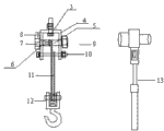
2 lifting instruments of Fig. 1 overhead ground wire ratchet wrench hand-type overall structure sketch map;
Fig. 2 is a lifting instrument jig part sketch map;
Fig. 3 is a lifting part sketch map;
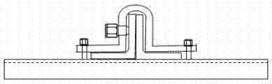
Fixed installation sketch map when Fig. 4 makes progress on suspension centre cross-arm angle bar plane for lifter;
Fig. 5 be the lifter jig on suspension centre cross-arm angle bar plane the fixedly sketch when downward.
Among the figure: jig 1, jig jackscrew 2, connect screw 3, crane boom 4, coiling steel pipe 5, coiling hanging hole 6, ratchet 7, ratchet 8, spanner 9, fixedly screw mandrel 10, steel wire rope 11, suspension hook 12, ratchet spanner 13, fixed screw 14, channel-section steel 15.
Embodiment
Like Fig. 1,2,3,4, shown in 5; 2 lifting instruments of a kind of overhead ground wire ratchet wrench hand-type; Constitute by the lifter of channel-section steel 15 two ends connection and the jig 1 of channel-section steel 15 middle parts setting; Described jig 1 is for being enclosed within the convex structure on the symmetry angle steel arranged side by side on the iron tower, and the limit, convex structure two ends of jig 1 is provided with fixed screw 14, and the concave slot of jig 1 convex structure is provided with jackscrew 2;
Said lifter is made up of crane boom 4, coiling steel pipe 5, ratchet 7, ratchet 8, spanner 9, the fixedly screw mandrel 10 of crane boom, steel wire rope 11, suspension hook 12; Crane boom 4 is a trench structure; Crane boom 4 bottom lands link to each other with channel-section steel 15 through connecting screw 3; Crane boom 4 trough rims are provided with coiling steel pipe 5 and fixing screw mandrel 10, and said coiling steel pipe 5 is provided with the coiling hanging hole 6 of steel wire rope 11, and steel wire rope 11 is linked to each other with fixing screw mandrel 10 through suspension hook 12 by coiling steel pipe 5; Said coiling steel pipe 5 one ends are provided with ratchet 7, ratchet 7 and ratchet 8 engagements; Said coiling steel pipe 5 other ends are provided with the spanner 9 that cooperates with ratchet spanner 13.
This line lifter comprises top jig 1; Lifting part two parts that the bottom is made up of two lifters constitute; Top jig 1 is installed on the hanging point angle steel 16; Fixing with jackscrew 2; For the ease of dismounting, this crane boom 4 links to each other with jig 1 through connecting screw 3, and crane boom 4 is provided with coiling steel pipe 5; Coiling steel pipe one end be provided with ratchet 7, ratchet top crane boom 4 be provided with pawl-and-gearing cooperate realize that automatic blocking prevents that tubulose bobbin winoler 5 from reversing, tubulose bobbin winoler 5 is provided with that hanging wire hole 6 links to each other with steel wire rope 11,5 other end settings of tubulose bobbin winoler and ratchet spanner 13 are supporting spanner 9, the steel pipe 5 that winds the line links to each other with suspension hook 12 through steel wire rope 11 with set bolt 10.
During use suspension hook 12 is hung on the ground wire; Be installed in the spanner 9 of two lifters respectively with two ratchet spanneres 13; Rotating two spanners 9 simultaneously rotates coiling steel pipe 5 to tighten up steel wire rope 11 ground wire is promoted; Ratchet spanner 13 is designed to extension type, promotes strength with increasing so that the decreased food of the flexible ratchet spanner 13 of base area uniaxial stress improves hoisting velocity.Use ratchet spanner both can adopt 360 ° of rotations, also can determine rotation amplitude as required and needn't remove sleeve and be inserted in again, shake pause in the process ratchet 7 that can be automatically locked through the ratchet 8 of band spring.
The course of work
During use, jig 1 is fixed on the cross-arm through channel-section steel 15 and jig fixed screw 14, fixing with jackscrew 2; Crane boom 4 usefulness are connected screw to link to each other with jig 1; Put down the suspension hook 12 at two ends, make suspension hook 12 collude two ends respectively and live on the overhead ground wire, then ratchet spanner 13 is installed in respectively on the spanner 9; Clockwise rotate two ends spanner 9 with ratchet spanner 13 simultaneously; Coiling steel pipe 5 is rotated tighten up steel wire rope 11 lifting overhead ground wires, make overhead ground wire break away from the pulley block position, when ground wire rises to the correct position that can install, stop to promote; Ratchet 8 on the crane boom ratchet 7 that will be automatically locked prevents its reverse, and at this moment the operating personnel just can remove pulley block and carries out the ground wire suspension clamp and install.It should be noted that in operating process; All can cause the variation of stress and lifting strength because of the variation of the size of span and hoisting depth; Ratchet spanner 13 is designed to extension type; Can be so that the length of base area uniaxial stress adjustment ratchet spanner 13 handles improves hoisting velocity and promotes strength with increasing.
Claims (2)
1. 2 lifting instruments of an overhead ground wire ratchet wrench hand-type; It is characterized in that: constitute by the lifter of channel-section steel (15) two ends connection and the jig (1) of channel-section steel (15) middle part setting; Described jig (1) is the convex structure on the symmetry angle steel arranged side by side; The limit, convex structure two ends of jig (1) is provided with fixed screw (14), and the concave slot of jig (1) convex structure is provided with jackscrew (2).
2. 2 lifting instruments of a kind of overhead ground wire ratchet wrench hand-type as claimed in claim 1; It is characterized in that: said lifter is made up of crane boom (4), coiling steel pipe (5), ratchet (7), ratchet (8), spanner (9), the fixedly screw mandrel (10) of crane boom, steel wire rope (11), suspension hook (12); Crane boom (4) is a trench structure; Crane boom (4) bottom land links to each other with channel-section steel (15) through connecting screw (3); Crane boom (4) trough rim is provided with coiling steel pipe (5) and fixing screw mandrel (10); Said coiling steel pipe (5) is provided with the coiling hanging hole (6) of steel wire rope (11), and steel wire rope (11) is linked to each other with fixing screw mandrel (10) through suspension hook (12) by coiling steel pipe (5); Said coiling steel pipe (5) one ends are provided with ratchet (7), ratchet (7) and ratchet (8) engagement; Said coiling steel pipe (5) other end is provided with the spanner (9) that cooperates with ratchet spanner (13).
Priority Applications (1)
| Application Number | Priority Date | Filing Date | Title |
|---|---|---|---|
| CN2011202343741U CN202190019U (en) | 2011-07-05 | 2011-07-05 | Aerial earth wire ratchet wrench type two-point lifting tool |
Applications Claiming Priority (1)
| Application Number | Priority Date | Filing Date | Title |
|---|---|---|---|
| CN2011202343741U CN202190019U (en) | 2011-07-05 | 2011-07-05 | Aerial earth wire ratchet wrench type two-point lifting tool |
Publications (1)
| Publication Number | Publication Date |
|---|---|
| CN202190019U true CN202190019U (en) | 2012-04-11 |
Family
ID=45921453
Family Applications (1)
| Application Number | Title | Priority Date | Filing Date |
|---|---|---|---|
| CN2011202343741U Expired - Fee Related CN202190019U (en) | 2011-07-05 | 2011-07-05 | Aerial earth wire ratchet wrench type two-point lifting tool |
Country Status (1)
| Country | Link |
|---|---|
| CN (1) | CN202190019U (en) |
Cited By (4)
| Publication number | Priority date | Publication date | Assignee | Title |
|---|---|---|---|---|
| CN105846356A (en) * | 2016-06-07 | 2016-08-10 | 国家电网公司 | Ground wire lifting fixture of steel tube tower for power transmission line |
| CN106329389A (en) * | 2016-10-27 | 2017-01-11 | 国网浙江省电力公司绍兴供电公司 | Hoisting device for large-tonnage live wire |
| CN106684756A (en) * | 2017-01-19 | 2017-05-17 | 国网山东省电力公司临沂供电公司 | Power transmission angle iron tower conductor and ground wire lifting tool and application method of the same |
| CN108529471A (en) * | 2018-05-31 | 2018-09-14 | 国家电网公司 | Portable overhead ground wire lifting device |
-
2011
- 2011-07-05 CN CN2011202343741U patent/CN202190019U/en not_active Expired - Fee Related
Cited By (5)
| Publication number | Priority date | Publication date | Assignee | Title |
|---|---|---|---|---|
| CN105846356A (en) * | 2016-06-07 | 2016-08-10 | 国家电网公司 | Ground wire lifting fixture of steel tube tower for power transmission line |
| CN106329389A (en) * | 2016-10-27 | 2017-01-11 | 国网浙江省电力公司绍兴供电公司 | Hoisting device for large-tonnage live wire |
| CN106329389B (en) * | 2016-10-27 | 2018-04-10 | 国网浙江省电力公司绍兴供电公司 | A kind of lifting device of large-tonnage live wire |
| CN106684756A (en) * | 2017-01-19 | 2017-05-17 | 国网山东省电力公司临沂供电公司 | Power transmission angle iron tower conductor and ground wire lifting tool and application method of the same |
| CN108529471A (en) * | 2018-05-31 | 2018-09-14 | 国家电网公司 | Portable overhead ground wire lifting device |
Similar Documents
| Publication | Publication Date | Title |
|---|---|---|
| CN102237655A (en) | Method and tool for lifting overhead ground wire | |
| CN202190019U (en) | Aerial earth wire ratchet wrench type two-point lifting tool | |
| CN207339088U (en) | Transmission line of electricity straight line pole aerial earth wire overhauls stent | |
| CN202190018U (en) | Overhead ground wire ratchet wrench wire-lifting tool | |
| CN201171148Y (en) | Machine for supporting overhead pround wire | |
| CN104242152A (en) | Lifting device for lifting overhead ground wire on straight concrete pole | |
| CN201190443Y (en) | Embraced Bar special for tower set | |
| CN104003291B (en) | A kind of power plant boiler equipment installation single track is walked suspender | |
| CN103311847A (en) | High-voltage cable clamper | |
| CN201758338U (en) | Motor stator lifting fixture | |
| CN201825686U (en) | Brick setter | |
| CN202488034U (en) | Lifting device for electric transmission line of angle iron tower | |
| CN202197048U (en) | Double angle steel hanging point lifting and connecting tool for tower use | |
| CN202405695U (en) | Lifting tool for overhead ground wire of steel pipe pole | |
| CN202183573U (en) | Rocker type two-point lifting tool of overhead ground wire | |
| CN203536866U (en) | Tripod line laying device | |
| CN102237654B (en) | Method for replacing jumper string using tool at double angle hanging point | |
| CN204167793U (en) | Straight line steel tube tower side, double loop cross-arm jig | |
| CN107732789B (en) | Overhead line wire-stringing device | |
| CN202197047U (en) | Rocking bar type overhead ground wire lifting device | |
| CN203660422U (en) | 500 kV overhead ground wire lifting tool | |
| CN105110202A (en) | Boom-rotating type hoisting support for pole-mounted switch | |
| CN206110810U (en) | Fixed armful of pole structure of staple bolt that slides | |
| CN202840363U (en) | Insulated lifting bracket for tension insulator chain of 1000-kV extra-high voltage alternating current circuit | |
| CN103487910A (en) | Optical cable tightener |
Legal Events
| Date | Code | Title | Description |
|---|---|---|---|
| C14 | Grant of patent or utility model | ||
| GR01 | Patent grant | ||
| C17 | Cessation of patent right | ||
| CF01 | Termination of patent right due to non-payment of annual fee |
Granted publication date: 20120411 Termination date: 20120705 |