CN201683823U - Household back rubbing and massaging manipulator - Google Patents
Household back rubbing and massaging manipulator Download PDFInfo
- Publication number
- CN201683823U CN201683823U CN2010202163496U CN201020216349U CN201683823U CN 201683823 U CN201683823 U CN 201683823U CN 2010202163496 U CN2010202163496 U CN 2010202163496U CN 201020216349 U CN201020216349 U CN 201020216349U CN 201683823 U CN201683823 U CN 201683823U
- Authority
- CN
- China
- Prior art keywords
- stepper motor
- shaft
- slide block
- installing rack
- driving
- Prior art date
- Legal status (The legal status is an assumption and is not a legal conclusion. Google has not performed a legal analysis and makes no representation as to the accuracy of the status listed.)
- Expired - Fee Related
Links
Images


Abstract
The utility model discloses a household back rubbing and massaging manipulator which is characterized in that: the household back rubbing and massaging manipulator mainly comprises a frame (1), a left-right moving mechanism (2), an up-down moving mechanism (3), a front-back telescopic mechanism (4) and a front-end back rubbing head mechanism (5); the left-right moving mechanism (2) is arranged on a cross beam of the frame (1); the upper and lower parts of the up-down moving mechanism (3) are respectively arranged on upper and lower guide rods (105, 111), and are connected with a synchronous belt (104) in the left-right moving mechanism (2); the front-back telescopic mechanism (4) is arranged on a sliding block (306) of the up-down moving mechanism (3), and the front-end back rubbing head mechanism (5) is arranged on the front-back telescopic mechanism (4). The economical and practical household back rubbing and massaging manipulator also has the characteristics of simple structure, convenient installation and easy use.
Description
Technical field
The utility model relates to a kind of family expenses health care auxiliary equipment, especially a kind of multi-function device that integrates chopping, massages, specifically a kind of domestic back rubbing and massaging manipulator.
Background technology
In recent years, along with the continuous improvement of people's living standard and housing condition, being in has a bath more and more becomes a kind of custom.But because the human body structural reason, people clean very inconvenient when having a bath to the oneself at back, and back portion is furnished with a lot of important acupuncture points, if can effectively massage these acupuncture points, are very helpful to the healthy of people so.But show according to investigations, less aspect the research of chopping, massaging manipulator.Just the various back rubbing devices of selling in the market are function singleness mostly, and the very flexible of machine itself designs not enough hommization, intellectuality, and the price of product is also very high, and marketing has very big difficulty.
The back is cleaned and the massage demand during at people's bathing, the utility model proposes a kind of novel household chopping and massaging manipulator.It can simulate the chopping and the massaging action of staff preferably, pursues health and healthy demand thereby satisfy people.
Summary of the invention
The purpose of this utility model is to need to help by others at chopping of present family and massage, and a difficult problem that can't self-service realization designs a kind of multi-functional domestic back rubbing and massaging manipulator.
The technical solution of the utility model is:
A kind of domestic back rubbing and massaging manipulator, it is characterized in that it mainly comprises framework 1, left/right movement device 2, reciprocating mechanism 3, elastic mechanism 4 and front end chopping head mechanism 5, front end chopping head mechanism 5 is installed in the elastic mechanism 4, elastic mechanism 4 is installed on the slide block 306 of reciprocating mechanism 3, upper and lower two of reciprocating mechanism 3 is held respectively and is sleeved on upper and lower guide rod 105, on 111 and with left/right movement device 2 in be with 104 to link to each other synchronously, left/right movement device 2 is installed on the crossbeam of framework 1.
Described left/right movement device 1 mainly is made up of stepper motor 101, shaft coupling 102, synchronous cog belt 104; Stepper motor 101 is installed on the belt wheel installing plate 109, stepper motor 101 links to each other with driving shaft 103 by shaft coupling 102, driving shaft is installed between belt wheel installing plate 109 and the entablature 112, on the driving shaft 103 driving wheel is installed, driven shaft 107 also is installed between belt wheel installing plate 109 and the entablature 112, on the driven shaft 107 driven pulley is installed, driving shaft 103 and driven shaft 107 lay respectively at the both sides of framework 1, synchronous cog belt 104 is installed on driving wheel and the driven pulley, and synchromesh gear shape 104 links to each other with the deckle board 314 of reciprocating mechanism 2 by connector.
Described reciprocating mechanism 3 mainly is made up of stepper motor 301, synchronous cog belt 312, slide block 306 and deckle board 314, stepper motor 301 is installed on the motor mounting plate 303, motor mounting plate 303 is fixed on the bottom of deckle board 314, stepper motor 301 links to each other with driving shaft 304 by shaft coupling 302, driving wheel 311 is installed on the driving shaft 304, on the top of deckle board 314 driven shaft 308 is installed, driven pulley 313 is installed on the driven shaft 308, and synchronous cog belt 312 is installed on driving wheel 311 and the driven pulley 313; Slide block 306 is installed on the guide rail 305 that is fixed on the deckle board 314, and slide block 306 links to each other with synchronous cog belt 312, and the connecting plate 307 that is used to install elastic mechanism 4 links to each other with slide block 306; Described deckle board 314 is installed on the upper and lower guide rod 105,111 by last lower carriage 315,316.
The two ends of described driving shaft 304 and driven shaft 308 are bearing in respectively in the U-shaped side plate 310.
Described elastic mechanism 4 mainly is made up of installing rack 414, stepper motor 401, synchronous cog belt 404, guide rail 407 and slide block 408, one end of installing rack 414 is fixed on the connecting plate 307 of reciprocating mechanism 3, stepper motor 401 is installed in a side of installing rack 414, it links to each other with driving shaft 403 by shaft coupling 402, driving wheel 405 is installed on the driving shaft 403, and synchronous cog belt 404 is installed in driving wheel 405 and is positioned on the driven pulley 409 of installing rack 414 other ends; Guide rail 407 is installed in the installing rack 414, slide block 408 be installed on the guide rail 407 and with the tooth form synchronous belt 404 synchronous elastic motion of continuous cropping mutually, front end chopping head mechanism 5 is installed on the slide block 408.
Described front end chopping head mechanism 5 mainly by installing rack 415, stepper motor 410, bevel gear 411, rub head axle 412 with the hands and rub 413 with the hands and form, installing rack 415 is fixed on the slide block 408 in the elastic mechanism 4, stepper motor 410 is installed in the installing rack 415, bevel gear 411 is installed on the output shaft of stepper motor 410, rub 413 with the hands and be installed in and rub with the hands on the head axle 412, rub head axle 412 with the hands and be installed with driving bevel gear 416 with bevel gear 411 engagements.
The beneficial effects of the utility model are:
The utility model has overcome most of back rubbing device function singlenesses, designs not enough hommization, intellectuality, and defective such as cost an arm and a leg.Integrate chopping, massage function, the mode that the motion of employing four direction matches provides the device of a kind of hand rubbing of anthropomorphic dummy preferably back of the body with massage.
The utlity model has chopping, massage functions, its functional diversities; Adopt active chopping thought, humanization designing; Can be good at simulating chopping, the massaging action of staff; The multiple degrees of freedom routing motion, design is intelligent; Simple to operation, economical and practical.
The utility model has chopping, massage functions concurrently, and its functional diversities is safe and reliable, can be used as daily household electrical appliance and uses.
The technical data that the utility model has changed present chopping aspect all is based on the design of passive type chopping thought, existing chopping mode needs people's back to press close on the back rubbing device, and the back will initiatively go to cater to the motion of back rubbing device, and it uses inconvenience, designs not enough hommization.The utility model adopts the design philosophy of active chopping.During chopping, people do not need to cater to the motion of back-rubbing machine, but back rubbing device moves the back of initiatively going to cater to the people, and back rubbing device is by passive changes active, and it more can embody the hommization level of machine.
Movement locus design when chopping of the present utility model and massaging manipulator are based on the staff scrubbing back and massaging, it can well simulate the scrubbing back and massaging action of staff, thereby makes people feel more comfortable.
Chopping of the present utility model and massaging manipulator adopt the multiple degrees of freedom routing motion, thereby can better simulate the scrubbing back and massaging action of staff, and multiple checkout gear is installed on it, as encoder, power sensor etc., can well detection speed and physical quantity such as dynamics, it designs intelligent.
The utility model is simple in structure, and is easy for installation, uses easily, economical and practical.
Can obtain different choppings, the speed of massage by the control rotating speed of motor;
Structural design compactness, reasonable is convenient to move;
It is simple to operation, economical and practical.
Description of drawings
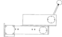
Fig. 1 is a structural representation of the present utility model.
Fig. 2 is the utility model move left and right part-structure schematic diagram.
Among Fig. 2: 101. motors, 102. shaft couplings, 103. driving shafts 104. are with 105. top guide bars, 106. synchronous pulleys, 107. driven shafts, 108. bearing (ball) covers, 109. belt wheel installing plates, 110. aluminium section bar supports, 111. lower guide rods, 112. entablatures synchronously.
Fig. 3 is the structural representation of reciprocating mechanism of the present utility model.
Fig. 4 is the left view of Fig. 3.
Among Fig. 3, Fig. 4: 301 motors, 302. shaft couplings, 303. motor mounting plates, 304. driving shafts, 305. guide rails, 306. slide blocks, 307. connecting plates, 308. driven shafts, 309. bearing (ball) covers, 310 side plates, 311. driving wheels 312. are with 313. driven pulleys, 314 deckle boards synchronously.
Fig. 5 is the structural representation of elastic mechanism of the utility model and front end chopping head mechanism.
Fig. 6 is the vertical view of Fig. 4.
Among Fig. 5,6: 401. synchronous motors, 402. shaft couplings, 403. driving shafts 404. are with 405. driving wheels, 406. guide rail installing plates, 407. guide rails, 408. slide blocks, 409. driven pulleys, 410. synchronous motors, 411. bevel gears 412. to rub head axle 413. choppings 414. elastic mechanisms installing rack 415. a choppings installing rack 416 with the hands synchronously and are driven bevel gear;
The specific embodiment
Below in conjunction with the drawings and specific embodiments the utility model is further described.
Shown in Fig. 1-6.
A kind of domestic back rubbing and massaging manipulator, it mainly comprises framework 1, left/right movement device 2, reciprocating mechanism 3, elastic mechanism 4 and front end chopping head mechanism 5, front end chopping head mechanism 5 is installed in the elastic mechanism 4, elastic mechanism 4 is installed on the slide block 306 of reciprocating mechanism 3, upper and lower two of reciprocating mechanism 3 is held respectively and is sleeved on upper and lower guide rod 105, on 111 and with left/right movement device 2 in be with 104 to link to each other synchronously, left/right movement device 2 is installed on the crossbeam of framework 1.As shown in Figure 1.
Left/right movement device 2 wherein, reciprocating mechanism 3, elastic mechanism 4 and front end chopping head mechanism 5 also can adopt the structure shown in Fig. 2-6 except that can designing voluntarily as required.
Wherein left/right movement device 1 is mainly by stepper motor 101, shaft coupling 102, synchronous cog belt 104 is formed, as shown in Figure 2, stepper motor 101 is installed on the belt wheel installing plate 109, stepper motor 101 links to each other with driving shaft 103 by shaft coupling 102, driving shaft is installed between belt wheel installing plate 109 and the entablature 112, on the driving shaft 103 driving wheel is installed, driven shaft 107 also is installed between belt wheel installing plate 109 and the entablature 112, on the driven shaft 107 driven pulley is installed, driving shaft 103 and driven shaft 107 lay respectively at the both sides of framework 1, synchronous cog belt 104 is installed on driving wheel and the driven pulley, and synchromesh gear shape 104 links to each other with the deckle board 314 of reciprocating mechanism 2 by connector.
Reciprocating mechanism 3 mainly is made up of stepper motor 301, synchronous cog belt 312, slide block 306 and deckle board 314, shown in Fig. 3,4, stepper motor 301 is installed on the motor mounting plate 303, motor mounting plate 303 is fixed on the bottom of deckle board 314, stepper motor 301 links to each other with driving shaft 304 by shaft coupling 302, driving wheel 311 is installed on the driving shaft 304, on the top of deckle board 314 driven shaft 308 is installed, driven pulley 313 is installed on the driven shaft 308, and synchronous cog belt 312 is installed on driving wheel 311 and the driven pulley 313; Slide block 306 is installed on the guide rail 305 that is fixed on the deckle board 314, and slide block 306 synchronous cog belts 312 link to each other, and the connecting plate 307 that is used to install elastic mechanism 4 links to each other with slide block 306; Described deckle board 314 is installed on the lower guide rod 105,111 by last lower carriage 315,316.The two ends of driving shaft 304 and driven shaft 308 are bearing in (as shown in Figure 4) in the U-shaped side plate 310 respectively.
Elastic mechanism 4 mainly is made up of installing rack 414, stepper motor 401, synchronous cog belt 404, guide rail 407 and slide block 408, one end of installing rack 414 is fixed on the connecting plate 307 of reciprocating mechanism 3, stepper motor 401 is installed in a side of installing rack 414, it links to each other with driving shaft 403 by shaft coupling 402, driving wheel 405 is installed on the driving shaft 403, and synchronous cog belt 404 is installed in driving wheel 405 and is positioned on the driven pulley 409 of installing rack 414 other ends; Guide rail 407 is installed in the installing rack 414, slide block 408 be installed on the guide rail 407 and with the tooth form synchronous belt 404 synchronous elastic motion of continuous cropping mutually, front end chopping head mechanism 5 is installed on the slide block 408.Shown in Fig. 5,6 front end chopping head mechanism 5 mainly by installing rack 415, stepper motor 410, bevel gear 411, rub head axle 412 with the hands and rub 413 with the hands and form, installing rack 415 is fixed on the slide block 408 in the elastic mechanism 4, stepper motor 410 is installed in the installing rack 415, bevel gear 411 is installed on the output shaft of stepper motor 410, rub 413 with the hands and be installed in and rub with the hands on the head axle 412, rub head axle 412 with the hands and be installed with driving bevel gear 416 with bevel gear 411 engagements.
Domestic back rubbing of the present utility model as seen from Figure 1 and massaging manipulator mainly by framework (can adopt aluminium section bar to build), move left and right part, move up and down part, elastic part, front end chopping head part, control circuit six major parts and form.Move left and right part, move up and down part, elastic part and front end chopping head part and be fixed on the aluminium section bar framework, the motion of four direction cooperatively interacts, and realizes the chopping function.Control circuit partly is installed in the bottom of aluminium section bar framework.
(1) aluminium section bar framework
Whole framework adopts industrial aluminum profile to build, and its good looking appearance is economical and practical, easy installation and removal.
(2) move left and right part
Move left and right partly realizes the side-to-side movement of whole frame, drives the synchronous cog belt side-to-side movement by stepper motor, thereby the mechanical arm that is fixed on the synchronous cog belt also can be moved with synchronous cog belt.Left/right movement device mainly is made up of stepper motor, shaft coupling, linear bearing, synchronous cog belt.Left/right movement device is fixed on the aluminium section bar, drives the synchronous cog belt move left and right by stepper motor, thereby makes the manipulator move left and right.In order to make the manipulator can even running, the below upwards be equipped with guiding mechanism thereon, realizes guide effect by linear bearing.
(3) move up and down part
Reciprocating mechanism mainly is made up of stepper motor, synchronous cog belt, two guide rail slide block mechanism.Reciprocating mechanism is fixed on the left/right movement device by linear bearing, and drives elastic mechanism and front end chopping head moves.The guiding mechanism of band adopts two guide rail slide block mechanisms synchronously.
(4) elastic part
Elastic mechanism mainly is made up of stepper motor, synchronous cog belt, guide rail slide block mechanism.Elastic mechanism is fixed on the reciprocating mechanism, and it is flexible back and forth to drive front end chopping head.
(5) front end chopping head part
Front end chopping head mainly is made up of stepper motor, bevel gear, stranding head, can realize 60 ° swing back and forth, and rubs head with the hands and can freely match.
(6) control circuit part
Control circuit partly adopts the Single-chip Controlling stepper motor, thereby realizes the motion control of entire mechanism.
Claims (6)
1. domestic back rubbing and massaging manipulator, it is characterized in that it mainly comprises framework (1), left/right movement device (2), reciprocating mechanism (3), elastic mechanism (4) and front end chopping head mechanism (5), left/right movement device (2) is installed on the crossbeam of framework (1), on the reciprocating mechanism (3), following two parts are contained in respectively, lower guide rod (105,111) go up and link to each other with synchronous band (104) in the left/right movement device (2), elastic mechanism (4) is installed on the slide block (306) of reciprocating mechanism (3), and front end chopping head mechanism (5) is installed in the elastic mechanism (4).
2. domestic back rubbing according to claim 1 and massaging manipulator is characterized in that described left/right movement device (2) mainly is made up of stepper motor (101), shaft coupling (102), synchronous cog belt (104); Stepper motor (101) is installed on the belt wheel installing plate (109), stepper motor (101) links to each other with driving shaft (103) by shaft coupling (102), driving shaft is installed between belt wheel installing plate (109) and the entablature (112), driving shaft is equipped with driving wheel on (103), driven shaft (107) also is installed between belt wheel installing plate (109) and the entablature (112), driven shaft is equipped with driven pulley on (107), driving shaft (103) and driven shaft (107) lay respectively at the both sides of framework (1), synchronous cog belt (104) is installed on driving wheel and the driven pulley, and synchromesh gear shape (104) links to each other with the deckle board (314) of reciprocating mechanism (3) by connector.
3. domestic back rubbing according to claim 1 and massaging manipulator, it is characterized in that described reciprocating mechanism (3) is mainly by stepper motor (301), synchronous cog belt (312), slide block (306) and deckle board (314) are formed, stepper motor (301) is installed on the motor mounting plate (303), motor mounting plate (303) is fixed on the bottom of deckle board (314), stepper motor (301) links to each other with driving shaft (304) by shaft coupling (302), driving wheel (311) is installed on the driving shaft (304), on the top of deckle board (314) driven shaft (308) is installed, driven pulley (313) is installed on the driven shaft (308), and synchronous cog belt (312) is installed on driving wheel (311) and the driven pulley (313); Slide block (306) is installed on the guide rail (305) that is fixed on the deckle board (314), and slide block (306) links to each other with synchronous cog belt (312), and the connecting plate (307) that is used to install elastic mechanism (4) links to each other with slide block (306); Described deckle board (314) is installed on the upper and lower guide rod (105,111) by last lower carriage (315,316).
4. domestic back rubbing according to claim 3 and massaging manipulator is characterized in that the two ends of described driving shaft (304) and driven shaft (308) are bearing in respectively in the U-shaped side plate (310).
5. domestic back rubbing according to claim 1 and massaging manipulator, it is characterized in that described elastic mechanism (4) is mainly by installing rack (414), stepper motor (401), synchronous cog belt (404), guide rail (407) and slide block (408) are formed, one end of installing rack (414) is fixed on the connecting plate (307) of reciprocating mechanism (3), stepper motor (401) is installed in a side of installing rack (414), it links to each other with driving shaft (403) by shaft coupling (402), driving wheel (405) is installed on the driving shaft (403), and synchronous cog belt (404) is installed in driving wheel (405) and is positioned on the driven pulley (409) of installing rack (414) other end; Guide rail (407) is installed in the installing rack (414), slide block (408) be installed in that guide rail (407) is gone up and with tooth form synchronous belt (404) the synchronous elastic motion of continuous cropping mutually, front end chopping head mechanism (5) is installed on the slide block (408).
6. domestic back rubbing according to claim 1 and massaging manipulator, it is characterized in that described front end chopping head mechanism (5) is mainly by installing rack (415), stepper motor (410), bevel gear (411), rubbing head spool (412) and stranding head (413) with the hands forms, installing rack (415) is fixed on the slide block (408) in the elastic mechanism (4), stepper motor (410) is installed in the installing rack (415), bevel gear (411) is installed on the output shaft of stepper motor (410), rub head (413) with the hands and be installed on the stranding head spool (412), rub head spool (412) with the hands and be installed with the driving bevel gear (416) that meshes with bevel gear (411).
Priority Applications (1)
| Application Number | Priority Date | Filing Date | Title |
|---|---|---|---|
| CN2010202163496U CN201683823U (en) | 2010-06-03 | 2010-06-03 | Household back rubbing and massaging manipulator |
Applications Claiming Priority (1)
| Application Number | Priority Date | Filing Date | Title |
|---|---|---|---|
| CN2010202163496U CN201683823U (en) | 2010-06-03 | 2010-06-03 | Household back rubbing and massaging manipulator |
Publications (1)
| Publication Number | Publication Date |
|---|---|
| CN201683823U true CN201683823U (en) | 2010-12-29 |
Family
ID=43372115
Family Applications (1)
| Application Number | Title | Priority Date | Filing Date |
|---|---|---|---|
| CN2010202163496U Expired - Fee Related CN201683823U (en) | 2010-06-03 | 2010-06-03 | Household back rubbing and massaging manipulator |
Country Status (1)
| Country | Link |
|---|---|
| CN (1) | CN201683823U (en) |
Cited By (6)
| Publication number | Priority date | Publication date | Assignee | Title |
|---|---|---|---|---|
| CN101862144A (en) * | 2010-06-03 | 2010-10-20 | 东南大学 | Domestic back rubbing and massaging manipulator |
| CN104721021A (en) * | 2015-04-09 | 2015-06-24 | 济南高达信息技术有限公司 | Wall-mounted automatic back massaging machine |
| CN107115050A (en) * | 2017-03-20 | 2017-09-01 | 海宁全家乐新能源有限公司 | A kind of free-standing automatic bathing machine |
| CN108937680A (en) * | 2018-09-06 | 2018-12-07 | 上海海事大学 | A kind of driven type human body back rubbing device |
| CN108938352A (en) * | 2018-06-13 | 2018-12-07 | 田秀丽 | A kind of medical scrape physiotherapeutic equipment |
| CN111449858A (en) * | 2020-04-14 | 2020-07-28 | 宁波大学 | Bathing protection device |
-
2010
- 2010-06-03 CN CN2010202163496U patent/CN201683823U/en not_active Expired - Fee Related
Cited By (7)
| Publication number | Priority date | Publication date | Assignee | Title |
|---|---|---|---|---|
| CN101862144A (en) * | 2010-06-03 | 2010-10-20 | 东南大学 | Domestic back rubbing and massaging manipulator |
| CN104721021A (en) * | 2015-04-09 | 2015-06-24 | 济南高达信息技术有限公司 | Wall-mounted automatic back massaging machine |
| CN107115050A (en) * | 2017-03-20 | 2017-09-01 | 海宁全家乐新能源有限公司 | A kind of free-standing automatic bathing machine |
| CN108938352A (en) * | 2018-06-13 | 2018-12-07 | 田秀丽 | A kind of medical scrape physiotherapeutic equipment |
| CN108938352B (en) * | 2018-06-13 | 2021-01-05 | 管翠梅 | Medical scraping physiotherapy instrument |
| CN108937680A (en) * | 2018-09-06 | 2018-12-07 | 上海海事大学 | A kind of driven type human body back rubbing device |
| CN111449858A (en) * | 2020-04-14 | 2020-07-28 | 宁波大学 | Bathing protection device |
Similar Documents
| Publication | Publication Date | Title |
|---|---|---|
| CN101862144A (en) | Domestic back rubbing and massaging manipulator | |
| CN201683823U (en) | Household back rubbing and massaging manipulator | |
| CN201182732Y (en) | Self-body massage bed | |
| CN201806623U (en) | Automatic back rubbing machine | |
| CN101647746B (en) | Adjusting device for realizing translation of massage head module position | |
| CN100463638C (en) | Scrubber | |
| CN109045624A (en) | Finger active-passive rehabilitation training device and its training method | |
| CN203389061U (en) | Multi-crank-arm massaging mechanical hand | |
| CN101019805A (en) | Household warming physiotherapeutic bed | |
| CN111358676A (en) | Massage armchair core and massage armchair | |
| CN201275021Y (en) | Bath eraser | |
| CN201200360Y (en) | Device for assisting bathing and scrubbing back | |
| CN2576153Y (en) | Vertical automatical rubbing bathing machine | |
| CN108523744A (en) | A kind of fully automatic energy-saving the elderly rubbing machine | |
| CN209235958U (en) | A kind of stranding leg mechanism of the elderly's rubbing machine | |
| CN203017324U (en) | Three-dimensional structure of movement of massage chair | |
| CN103070758A (en) | Wearable hand function rehabilitation training device | |
| CN211299712U (en) | Novel chair type back rubbing and massaging device for helping the aged | |
| CN102764192B (en) | Massage mechanism with back cushion | |
| CN2590563Y (en) | Back massaging up-down moving mechanism for electric massaging chair | |
| CN201469618U (en) | Adjusting device capable of translating position of massage head assembly | |
| CN202751747U (en) | Body builder with generator | |
| CN201286660Y (en) | Automatic bath rubber | |
| CN214415216U (en) | Massage armchair core and massage armchair | |
| CN219109275U (en) | Plane reciprocating type scrubbing device |
Legal Events
| Date | Code | Title | Description |
|---|---|---|---|
| C14 | Grant of patent or utility model | ||
| GR01 | Patent grant | ||
| CF01 | Termination of patent right due to non-payment of annual fee | ||
| CF01 | Termination of patent right due to non-payment of annual fee |
Granted publication date: 20101229 Termination date: 20170603 |