CN1180932C - Method and device for producing embossed web material and product made in this way - Google Patents
Method and device for producing embossed web material and product made in this way Download PDFInfo
- Publication number
- CN1180932C CN1180932C CNB998035610A CN99803561A CN1180932C CN 1180932 C CN1180932 C CN 1180932C CN B998035610 A CNB998035610 A CN B998035610A CN 99803561 A CN99803561 A CN 99803561A CN 1180932 C CN1180932 C CN 1180932C
- Authority
- CN
- China
- Prior art keywords
- projection
- group
- layer
- impression cylinder
- embossing
- Prior art date
- Legal status (The legal status is an assumption and is not a legal conclusion. Google has not performed a legal analysis and makes no representation as to the accuracy of the status listed.)
- Expired - Fee Related
Links
Images


Classifications
-
- B—PERFORMING OPERATIONS; TRANSPORTING
- B31—MAKING ARTICLES OF PAPER, CARDBOARD OR MATERIAL WORKED IN A MANNER ANALOGOUS TO PAPER; WORKING PAPER, CARDBOARD OR MATERIAL WORKED IN A MANNER ANALOGOUS TO PAPER
- B31F—MECHANICAL WORKING OR DEFORMATION OF PAPER, CARDBOARD OR MATERIAL WORKED IN A MANNER ANALOGOUS TO PAPER
- B31F1/00—Mechanical deformation without removing material, e.g. in combination with laminating
- B31F1/07—Embossing, i.e. producing impressions formed by locally deep-drawing, e.g. using rolls provided with complementary profiles
-
- B—PERFORMING OPERATIONS; TRANSPORTING
- B31—MAKING ARTICLES OF PAPER, CARDBOARD OR MATERIAL WORKED IN A MANNER ANALOGOUS TO PAPER; WORKING PAPER, CARDBOARD OR MATERIAL WORKED IN A MANNER ANALOGOUS TO PAPER
- B31F—MECHANICAL WORKING OR DEFORMATION OF PAPER, CARDBOARD OR MATERIAL WORKED IN A MANNER ANALOGOUS TO PAPER
- B31F2201/00—Mechanical deformation of paper or cardboard without removing material
- B31F2201/07—Embossing
- B31F2201/0707—Embossing by tools working continuously
- B31F2201/0715—The tools being rollers
- B31F2201/0723—Characteristics of the rollers
- B31F2201/073—Rollers having a multilayered structure
-
- B—PERFORMING OPERATIONS; TRANSPORTING
- B31—MAKING ARTICLES OF PAPER, CARDBOARD OR MATERIAL WORKED IN A MANNER ANALOGOUS TO PAPER; WORKING PAPER, CARDBOARD OR MATERIAL WORKED IN A MANNER ANALOGOUS TO PAPER
- B31F—MECHANICAL WORKING OR DEFORMATION OF PAPER, CARDBOARD OR MATERIAL WORKED IN A MANNER ANALOGOUS TO PAPER
- B31F2201/00—Mechanical deformation of paper or cardboard without removing material
- B31F2201/07—Embossing
- B31F2201/0707—Embossing by tools working continuously
- B31F2201/0715—The tools being rollers
- B31F2201/0723—Characteristics of the rollers
- B31F2201/0733—Pattern
-
- B—PERFORMING OPERATIONS; TRANSPORTING
- B31—MAKING ARTICLES OF PAPER, CARDBOARD OR MATERIAL WORKED IN A MANNER ANALOGOUS TO PAPER; WORKING PAPER, CARDBOARD OR MATERIAL WORKED IN A MANNER ANALOGOUS TO PAPER
- B31F—MECHANICAL WORKING OR DEFORMATION OF PAPER, CARDBOARD OR MATERIAL WORKED IN A MANNER ANALOGOUS TO PAPER
- B31F2201/00—Mechanical deformation of paper or cardboard without removing material
- B31F2201/07—Embossing
- B31F2201/0707—Embossing by tools working continuously
- B31F2201/0715—The tools being rollers
- B31F2201/0723—Characteristics of the rollers
- B31F2201/0738—Cross sectional profile of the embossments
-
- B—PERFORMING OPERATIONS; TRANSPORTING
- B31—MAKING ARTICLES OF PAPER, CARDBOARD OR MATERIAL WORKED IN A MANNER ANALOGOUS TO PAPER; WORKING PAPER, CARDBOARD OR MATERIAL WORKED IN A MANNER ANALOGOUS TO PAPER
- B31F—MECHANICAL WORKING OR DEFORMATION OF PAPER, CARDBOARD OR MATERIAL WORKED IN A MANNER ANALOGOUS TO PAPER
- B31F2201/00—Mechanical deformation of paper or cardboard without removing material
- B31F2201/07—Embossing
- B31F2201/0758—Characteristics of the embossed product
- B31F2201/0761—Multi-layered
- B31F2201/0764—Multi-layered the layers being nested
-
- B—PERFORMING OPERATIONS; TRANSPORTING
- B31—MAKING ARTICLES OF PAPER, CARDBOARD OR MATERIAL WORKED IN A MANNER ANALOGOUS TO PAPER; WORKING PAPER, CARDBOARD OR MATERIAL WORKED IN A MANNER ANALOGOUS TO PAPER
- B31F—MECHANICAL WORKING OR DEFORMATION OF PAPER, CARDBOARD OR MATERIAL WORKED IN A MANNER ANALOGOUS TO PAPER
- B31F2201/00—Mechanical deformation of paper or cardboard without removing material
- B31F2201/07—Embossing
- B31F2201/0771—Other aspects of the embossing operations
- B31F2201/0774—Multiple successive embossing operations
-
- B—PERFORMING OPERATIONS; TRANSPORTING
- B31—MAKING ARTICLES OF PAPER, CARDBOARD OR MATERIAL WORKED IN A MANNER ANALOGOUS TO PAPER; WORKING PAPER, CARDBOARD OR MATERIAL WORKED IN A MANNER ANALOGOUS TO PAPER
- B31F—MECHANICAL WORKING OR DEFORMATION OF PAPER, CARDBOARD OR MATERIAL WORKED IN A MANNER ANALOGOUS TO PAPER
- B31F2201/00—Mechanical deformation of paper or cardboard without removing material
- B31F2201/07—Embossing
- B31F2201/0771—Other aspects of the embossing operations
- B31F2201/0776—Exchanging embossing tools
-
- B—PERFORMING OPERATIONS; TRANSPORTING
- B31—MAKING ARTICLES OF PAPER, CARDBOARD OR MATERIAL WORKED IN A MANNER ANALOGOUS TO PAPER; WORKING PAPER, CARDBOARD OR MATERIAL WORKED IN A MANNER ANALOGOUS TO PAPER
- B31F—MECHANICAL WORKING OR DEFORMATION OF PAPER, CARDBOARD OR MATERIAL WORKED IN A MANNER ANALOGOUS TO PAPER
- B31F2201/00—Mechanical deformation of paper or cardboard without removing material
- B31F2201/07—Embossing
- B31F2201/0784—Auxiliary operations
- B31F2201/0787—Applying adhesive
-
- B—PERFORMING OPERATIONS; TRANSPORTING
- B31—MAKING ARTICLES OF PAPER, CARDBOARD OR MATERIAL WORKED IN A MANNER ANALOGOUS TO PAPER; WORKING PAPER, CARDBOARD OR MATERIAL WORKED IN A MANNER ANALOGOUS TO PAPER
- B31F—MECHANICAL WORKING OR DEFORMATION OF PAPER, CARDBOARD OR MATERIAL WORKED IN A MANNER ANALOGOUS TO PAPER
- B31F2201/00—Mechanical deformation of paper or cardboard without removing material
- B31F2201/07—Embossing
- B31F2201/0784—Auxiliary operations
- B31F2201/0792—Printing
-
- Y—GENERAL TAGGING OF NEW TECHNOLOGICAL DEVELOPMENTS; GENERAL TAGGING OF CROSS-SECTIONAL TECHNOLOGIES SPANNING OVER SEVERAL SECTIONS OF THE IPC; TECHNICAL SUBJECTS COVERED BY FORMER USPC CROSS-REFERENCE ART COLLECTIONS [XRACs] AND DIGESTS
- Y10—TECHNICAL SUBJECTS COVERED BY FORMER USPC
- Y10T—TECHNICAL SUBJECTS COVERED BY FORMER US CLASSIFICATION
- Y10T156/00—Adhesive bonding and miscellaneous chemical manufacture
- Y10T156/10—Methods of surface bonding and/or assembly therefor
- Y10T156/1002—Methods of surface bonding and/or assembly therefor with permanent bending or reshaping or surface deformation of self sustaining lamina
- Y10T156/1007—Running or continuous length work
- Y10T156/1023—Surface deformation only [e.g., embossing]
-
- Y—GENERAL TAGGING OF NEW TECHNOLOGICAL DEVELOPMENTS; GENERAL TAGGING OF CROSS-SECTIONAL TECHNOLOGIES SPANNING OVER SEVERAL SECTIONS OF THE IPC; TECHNICAL SUBJECTS COVERED BY FORMER USPC CROSS-REFERENCE ART COLLECTIONS [XRACs] AND DIGESTS
- Y10—TECHNICAL SUBJECTS COVERED BY FORMER USPC
- Y10T—TECHNICAL SUBJECTS COVERED BY FORMER US CLASSIFICATION
- Y10T156/00—Adhesive bonding and miscellaneous chemical manufacture
- Y10T156/17—Surface bonding means and/or assemblymeans with work feeding or handling means
- Y10T156/1702—For plural parts or plural areas of single part
- Y10T156/1712—Indefinite or running length work
- Y10T156/1737—Discontinuous, spaced area, and/or patterned pressing
-
- Y—GENERAL TAGGING OF NEW TECHNOLOGICAL DEVELOPMENTS; GENERAL TAGGING OF CROSS-SECTIONAL TECHNOLOGIES SPANNING OVER SEVERAL SECTIONS OF THE IPC; TECHNICAL SUBJECTS COVERED BY FORMER USPC CROSS-REFERENCE ART COLLECTIONS [XRACs] AND DIGESTS
- Y10—TECHNICAL SUBJECTS COVERED BY FORMER USPC
- Y10T—TECHNICAL SUBJECTS COVERED BY FORMER US CLASSIFICATION
- Y10T428/00—Stock material or miscellaneous articles
- Y10T428/24—Structurally defined web or sheet [e.g., overall dimension, etc.]
- Y10T428/24355—Continuous and nonuniform or irregular surface on layer or component [e.g., roofing, etc.]
- Y10T428/24446—Wrinkled, creased, crinkled or creped
- Y10T428/24455—Paper
- Y10T428/24463—Plural paper components
-
- Y—GENERAL TAGGING OF NEW TECHNOLOGICAL DEVELOPMENTS; GENERAL TAGGING OF CROSS-SECTIONAL TECHNOLOGIES SPANNING OVER SEVERAL SECTIONS OF THE IPC; TECHNICAL SUBJECTS COVERED BY FORMER USPC CROSS-REFERENCE ART COLLECTIONS [XRACs] AND DIGESTS
- Y10—TECHNICAL SUBJECTS COVERED BY FORMER USPC
- Y10T—TECHNICAL SUBJECTS COVERED BY FORMER US CLASSIFICATION
- Y10T428/00—Stock material or miscellaneous articles
- Y10T428/24—Structurally defined web or sheet [e.g., overall dimension, etc.]
- Y10T428/24479—Structurally defined web or sheet [e.g., overall dimension, etc.] including variation in thickness
- Y10T428/24562—Interlaminar spaces
-
- Y—GENERAL TAGGING OF NEW TECHNOLOGICAL DEVELOPMENTS; GENERAL TAGGING OF CROSS-SECTIONAL TECHNOLOGIES SPANNING OVER SEVERAL SECTIONS OF THE IPC; TECHNICAL SUBJECTS COVERED BY FORMER USPC CROSS-REFERENCE ART COLLECTIONS [XRACs] AND DIGESTS
- Y10—TECHNICAL SUBJECTS COVERED BY FORMER USPC
- Y10T—TECHNICAL SUBJECTS COVERED BY FORMER US CLASSIFICATION
- Y10T428/00—Stock material or miscellaneous articles
- Y10T428/24—Structurally defined web or sheet [e.g., overall dimension, etc.]
- Y10T428/24479—Structurally defined web or sheet [e.g., overall dimension, etc.] including variation in thickness
- Y10T428/24612—Composite web or sheet
-
- Y—GENERAL TAGGING OF NEW TECHNOLOGICAL DEVELOPMENTS; GENERAL TAGGING OF CROSS-SECTIONAL TECHNOLOGIES SPANNING OVER SEVERAL SECTIONS OF THE IPC; TECHNICAL SUBJECTS COVERED BY FORMER USPC CROSS-REFERENCE ART COLLECTIONS [XRACs] AND DIGESTS
- Y10—TECHNICAL SUBJECTS COVERED BY FORMER USPC
- Y10T—TECHNICAL SUBJECTS COVERED BY FORMER US CLASSIFICATION
- Y10T428/00—Stock material or miscellaneous articles
- Y10T428/24—Structurally defined web or sheet [e.g., overall dimension, etc.]
- Y10T428/24628—Nonplanar uniform thickness material
Abstract
For the production of a sheet product including at least two layers (V1,V2) it is suggested, among other things, an embossing device including a first pressure roller (5;105) interacting with a first and a second embossing cylinder (1,3;101,103) provided with respective points (1P,3P;101P,103P) on their cylindrical surface.
Description
Technical field
The present invention relates to a kind of method and apparatus that is used to produce the embossed sheet that constitutes by multilayer, and relate to the articles of sheet material of in this way making.
Prior art
In the production of the sheet paper products that is used for uses such as family, often to carry out the technology of embossing on a web material and produce bigger apparent thickness, good hygroscopicity, the flexibility and the decorative effect of touch.
Embossing sheet coiled material is used for producing napkin paper, toilet paper, napkin, paper handkerchief etc.Usually, coiled material is made of two-layer or multilayer, constitutes this which floor embossing respectively of coiled material, couples together for example gluing or other method of its connection means, for example layer sticking (ply-bonding) then.The articles of sheet material of Sheng Chaning has bigger flexibility and thickness in this way, and good hygroscopicity.
Usually the embossing of carrying out two-layer or multilayer with two kinds of methods be connected, promptly " protruding top is to protruding top " formula is connected with " nested " formula.Under first kind of situation, embossed material two-layer by being connected by lamination between the impression cylinder that has a parallel backward rotation axle at two.Two impression cylinders are provided with at least on the protruding top of lamination gap portion alignment, and described lamination gap is formed on the points of tangency between two cylinders.A kind of adhesive is applied on the projection of one of two embossed layers so that the zone that is in alignment with each other on the protruding top of two impression cylinders is connected with another layer is permanent, and its position is the position of the projection of another layer.The example of such embossing machine is at US-A-3, and 414,459, US-A-4,978,565, US-A-5,173,351, US-A-5,096,527, US-A-3,961,119, WO-A-9,720,687, WO-A-9,720,688, WO-A-9 describes in 720,689.
In other device, described layer connects by this way, and the projection of one deck is embedded in the cavity between the neighboring projection of another layer.In this case, two impression cylinders are not pressed against each other together at place, corresponding protruding top, and described two-layerly be laminated on together by a pressure roller, the surface interaction of this pressure roller and an impression cylinder is supported when coming out their gaps between impression cylinder two-layer on the described impression cylinder.
The example of this embossing type is at GB-A-1, and 225,440, US-A-3 has explanation and diagram in 694,300.
Usually, and though be protruding top to protruding top formula or nested type embossing, it is by in described how much and equally distributed projection on two-layer, the projection that is typically frustum of a cone or butt pyramid shape constitutes.In order to obtain the product of more attractive outward appearance, designed a kind of like this system, wherein difform projection combination with one another together, formed specific design.For example, US-A-4,320,162 have described a kind of raging system, wherein on each two-layer layer with the geometry with high density setting, equally distributed kick carries out embossing, forms tiny background embossing; Combine with low-density projection large-sized, complicated shape, formed ornamental figure.Similar products like is at WO-A-9, description arranged in 618,771.
The shortcoming of this system is, when hope changes decorative pattern, must make new a pair of impression cylinder or the impression cylinder that at least one is new, this not only needs to produce again whole decorative pattern, and needs to produce all protruding tops of the cylinder that produces the background embossing.
Goal of the invention
The method and apparatus that the purpose of this invention is to provide a kind of production embossing product, such embossing product comprises one first embossing and second embossing that more separates that is made of decorative pattern with widening, its mode is similar to US-A-4,320,162 descriptions, this product has higher quality.
Another object of the present invention provides a kind of embossing device and method, and it can change decorative pattern in more economical mode.
Another object of the present invention provides a kind of embossing method and device, and it can produce soft product, and can be by being used in combination the decorative effect that increases embossing with the adhesive of colour.
A further object of the invention provides a kind of embossing device, and it can be by changing existing raging system, producing in the mode of economy.
Summary of the invention
According to the present invention, those of ordinary skill in the art is by reading following description when can clearer understanding being arranged to these and further purpose and advantage.Described method comprises the steps:
Arranging embossing on the ground floor coiled material of the background patterns that constitutes by first group of projection in advance, thereby produce second group of projection on this ground floor coiled material, this second group of projection is stacked on first group of projection and has than bigger size of the projection of first group of projection and lower density;
Preferably, the second layer is connected on the ground floor of such embossing by gluing.
The second layer can be smooth, embossing pattern, embossing ornamental figure or embossing have been arranged background patterns and the ornamental figure of having powerful connections.
In a particularly advantageous embodiment of the present invention, second and the 3rd group of projection that is separately positioned on first and second layers produces by same impression cylinder, and two pressure rollers cooperate with this impression cylinder, like this, they have identical density and identical setting, and one another the inside.In this way, can be combined into one two-layer by adhesive being applied on the projection of the 3rd group of projection of the second layer, then lamination first and second layer coiled materials in the process that produces second group of projection.As already known, adhesive can be applied on all projections of the 3rd group or on some projections wherein.
In the embodiment of the practicality of the method according to this invention, can be by coming on the ground floor coiled material, to produce first and second groups of projections, described first pressure roller and the first and second impression cylinder mating reactions around one first pressure roller operation ground floor coiled material.Two impression cylinders comprise first and second groups of protruding tops respectively, and second group of protruding top compared with first group of protruding top has bigger size and lower density.
Second impression cylinder can be with the second pressure roller mating reaction so that produce the 3rd group of projection on the second layer.
The embossing of two coiled material layers can produce first and the 3rd group of projection with approximately equalised height.Perhaps, the height of the 3rd group of projection can be made the height greater than second group of projection.Connect two coiled material layers in this way, produce hollow space.These spaces have increased the pliability and the hygroscopicity of coiled material.
In another embodiment according to the inventive method, the second layer moves around first pressure roller, first and second impression cylinders and this pressure roller mating reaction.The second layer and contacting of first pressure roller occur in the downstream in the embossed zone of ground floor, and this ground floor is embossed between the impression cylinder and first pressure roller.In this way, second layer embossing on ground floor between first pressure roller and second impression cylinder, this second impression cylinder and the first pressure roller mating reaction.
Another kind of possibility is around second impression cylinder one second pressure roller to be set, and feeds the 3rd layer an of coiled material around second pressure roller between second pressure roller and second impression cylinder.The three-layer coil material is embossed by produce the 4th group of projection on it then; First, second and the 3rd layer are laminated on together between second impression cylinder and second pressure roller.Which floor can connect into integral body with adhesive for this, and this adhesive is applied at least a portion of the projection of the second group of projection that produces on the ground floor.By make adhesive soak the second layer and gluing the 3rd layer towards ground floor.
The embodiment that is used to carry out a kind of favourable device of the inventive method comprises a pressure roller that uses to match and act on first and second impression cylinders, and described impression cylinder has protruding top separately on its periphery.Two impression cylinders preferably have the protruding top of different densities, especially have bigger size and lower density on an impression cylinder, and have lower density and bigger size on another impression cylinder.
A kind of according to an embodiment of the invention multi-form, a kind of method that comprises the steps is provided:
According to the background patterns that forms by first group of projection, on two-layer, carry out first embossing respectively;
Again embossing has the one deck at least in decorative pattern two-layer, and this decorative pattern has bigger size than background patterns and than low-density.This background patterns is made of second group of projection, and this second group of jut is stacked on the projection of first group of projection of described background patterns; And
Connect described two-layer.
In practice, the projection of background patterns and the projection of decorative pattern can be formed on the identical faces of equivalent layer outstanding, particularly in the product that in the end connects in the face of the face of product inside.
In a preferred embodiment of the invention, the second group of projection that forms decorative pattern has bigger height than the first group of projection that forms background patterns, and two-layer position second group of projection links together by gluing.
For obtaining a kind of specific outward appearance, according to possible embodiment of this method, can will connect by colored adhesive which floor couple together, thereby make decorative pattern outstanding from the background of coiled material.
According to the present invention, the device that is used to produce a kind of coiled material with at least two embossing and articulamentum comprises:
Be used for first embossing units and first embossing units that is used for the second layer of ground floor, described first embossing units produces a background patterns on described first and second layers, and this background patterns is made of first group of projection;
One second embossing units, it is used for producing a decorative pattern at ground floor, and this decorative pattern is made of second group of projection, and the density of this second group of projection is less than the density of first group of projection, and this second group of jut is stacked on the described background patterns; And
Connect and the lamination element, it is used to connect described first and second layers.
More advantageously, provide an adhesive dispenser that interrelates with described second embossing units, this adhesive dispenser is used for linking together two-layer by gluing and lamination then to some projections supply adhesives of ground floor at least.
In this device a particularly advantageous embodiment, connect and to be connected described two-layerly at the projection position of decorative pattern with the lamination element, for this purpose, the height of the projection of this decorative pattern is greater than the height of background patterns.
In possible embodiment of this device, each of two first embossing units that is used for first and second layers comprises a pair of knurling rolls, and one of them knurling rolls is provided with protruding top and another knurling rolls are provided with a plastic surface; Perhaps, each (or at least one) comprises a pair of roller of being made by steel or other hard material.
Connect and the lamination element comprises, for example, an impression cylinder of second embossing units and the roller of a pairing, described impression cylinder is provided with the protruding top that is used to produce second group of projection, this second group of projection formation decorative pattern.
In different embodiment according to apparatus of the present invention, first embossing units that is used for ground floor comprises a pair of knurling rolls; Second embossing units comprises an impression cylinder, and this impression cylinder is provided with the protruding top that is used for producing second group of projection, and described second group of projection forms described decorative pattern, and this impression cylinder and a pressure roller mating reaction; First embossing units that is used for the second layer comprises that another is provided with the impression cylinder on protruding top, this impression cylinder and the pressure roller mating reaction with plastic surface.In this case, connection and lamination element can be made of with described another impression cylinder that is used for the second layer an impression cylinder of second embossing units that is used for ground floor, between described two impression cylinders, form a laminating area, in this zone, the protruding top of two impression cylinders interacts and connects two embossed layers.
The invention still further relates to the sheet material that forms by at least two embossing and articulamentum, it is characterized in that, described ground floor comprises a background embossing and one second embossing, this background embossing is made of first group of projection, this second embossing is made of the second group of projection that forms a decorative pattern, second group of projection has bigger size and lower density than first group of projection, and second group of projection is stacked on first group of projection; The described second layer comprises at least one background embossing, and this background embossing is made of one group of projection.
Other favorable characteristics and the embodiment of method of the present invention, device and product describe hereinafter with in the appended claims.
Brief description of drawings
By will clearer understanding being arranged to the present invention in conjunction with specification and accompanying drawing, this specification and accompanying drawing have been represented the embodiment of practicality of the present invention.Specifically:
Fig. 1 represents to be used to finish the schematic representation of apparatus according to the method for first embodiment of the invention;
Figure 1A and Figure 1B have represented the details that Fig. 1 amplifies;
Fig. 2 has represented the schematic section of the further amplification of the product that Fig. 1 device is produced;
Fig. 3 has schematically shown and has been used to finish the device of method in accordance with another embodiment of the present invention;
Fig. 3 A and Fig. 3 B have represented the details that Fig. 3 amplifies;
Fig. 4 represents the schematic cross section by the further amplification of the product of device production shown in Figure 3;
Fig. 5 represents in another embodiment, finishes the schematic representation of apparatus of the inventive method;
Fig. 6 represents the schematic diagram of another embodiment of embossing device according to the present invention;
The details that Fig. 6 A and 6B presentation graphs 6 amplify;
Fig. 7 has represented the amplification sectional view of a kind of product that can make by Fig. 6 device;
Fig. 8 represents the schematic diagram of another embodiment of embossing device according to the present invention;
Fig. 8 A has represented the details of the amplification of Fig. 8;
Fig. 9 has represented the amplification sectional view of a kind of product that can make by Fig. 8 device;
Figure 10 represents the schematic diagram of another embodiment of embossing device according to the present invention;
Figure 10 A and 10B have represented the details of the amplification of Figure 10;
Figure 11 has represented the amplification sectional view of a kind of product that can make by Figure 10 device;
Figure 12 represents the front view by a part of coiled material of method and apparatus production of the present invention;
Figure 13 represents the schematic diagram of another embodiment of the present invention;
Figure 13 A and 13B have represented the details that Figure 13 amplifies; And
Figure 14 represents the amplification sectional view that has the articles of sheet material of an embossed layers and a smooth layer that is attached thereto by one.
The detailed description of the preferred embodiment of the present invention
Fig. 1,1A, 1B and 2 have represented first embodiment of the present invention.Described device comprises one first impression cylinder 1 and one second impression cylinder 3.Two impression cylinders 1 and 3 have protruding top 1P and 3P separately respectively, respectively shown in zoomed-in view among Figure 1A and the 1B.Protruding top 1P has less size and bigger density than protruding top 3P.
One first pressure roller 5 and two impression cylinders 1 and 3 mating reactions, this pressure roller 5 is covered with the plastic deformation material, for example rubber covering layer 5A.With one second pressure roller 7 that also has of second impression cylinder, 3 mating reactions, this second pressure roller 7 is covered with plastic deformation material 7A equally.Impression cylinder 3 equally also is provided with the distributor of an adhesive, and total label 9 is represented this distributor.This is a kind of known type, and is not described in detail.
The operation of described device is as described below.The ground floor coiled material, for example one deck face tissue V1 is fed to first impression cylinder 1, centers on impression cylinder 1 back and on first pressure roller 5.Material layer V1 is extruded between impression cylinder 1 and pressure roller 5, and embossing on the protruding top 1P of impression cylinder 1.Similarly, the second material layer V2 of a paper wood is fed to second pressure roller 7, round this second pressure roller 7, and embossing between second pressure roller 7 and second impression cylinder 3.
Ground floor V1 round 5 operations of first pressure roller, arrives the roll gap between first pressure roller 5 and second impression cylinder 3 then, is stacked in the second material layer V2 top in the lamination gap that is fed between first pressure roller 5 and second impression cylinder 3 at this material layer V1.So, ground floor V1 embossing again between first pressure roller 5 and second impression cylinder 3, thereby the effect by protruding top 3P receives a kind of embossed pattern, and protruding top 3P has lower density and bigger size than the background patterns that the protruding top 1P by first impression cylinder 1 produces on one deck V1.With before second layer V2 is connected, adhesive C has been applied to by second impression cylinder 3 on the projection that produces on the second layer V2 at ground floor V1.In the lamination gap between second impression cylinder 3 and first pressure roller 5, two-layer being bonded in together.Adhesive is assigned to by second impression cylinder 3 on the part that produces on the second layer V2 or all projection by distributor 9.
Final products roughly illustrate in Fig. 2, represent first and second layers respectively once more at this V1, V2.Ground floor V1 comprises the projection P2 of first group of reduced size defining a background patterns and greater density and has large-size and more low-density second group of projection P4.Projection P2 is produced by the protruding top 1P of first impression cylinder 1, and projection P4 is produced by second impression cylinder 3.Two groups of projections produce by the pressure that pressure roller 5 is resisted against on corresponding impression cylinder 1 and 3.As can be seen from Figure 2, at projection P4 place, the projection P2 on the whole surface of initial layer of cover material V1 has been extruded and has been removed in a large number.Second layer V2 comprises the projection P6 of the 3rd series that produces by second impression cylinder 3, and thereby with material layer V1 on projection P4 with the identical placement that is provided with.The projection of the 3rd group of projection P6 is positioned at the inboard of second group of projection P4, and gluing in the latter by the adhesive C that is applied by distributor 9.
As can be seen from Figure 2, the degree of depth of projection P6 embossing is greater than the degree of depth of projection P4 embossing.This can be by being used in first pressure roller 5 cover layer 5A than the degree or the little and/or different pressure of plasticity of the cover layer 7A surrender of second pressure roller 7.In this way, by connecting two-layer V1 and V2, in the cavity between neighboring projection P6 and P4, between two-layer, stayed hollow space S.
Fig. 3,3A, 3B and 4 have represented a different embodiment of the present invention.At this, described device (shown in Fig. 3,3A, the 3B) also has one first impression cylinder 101, second impression cylinder 103, has equipped one first pressure roller 105 and second pressure roller 107 of having equipped a plastic cover layer 107A of a plastic cover layer 105A.
The axis of two impression cylinders 101 and 103 and two pressure rollers 105 and 107 is vertical alignment also.Impression cylinder 101 and pressure roller 105 mating reactions, and the latter and impression cylinder 103 mating reactions, this impression cylinder 103 again with pressure roller 107 mating reactions.Impression cylinder 103 is provided with the distributor 109 of an adhesive.
Shown in the details that Fig. 3 A amplifies, first impression cylinder 101 is loaded with protruding top 101P, and (seeing Fig. 3 B) second impression cylinder 103 is loaded with protruding top 103P, and protruding top 103P compares with the protruding top 101P of first impression cylinder 101 has bigger size and less density.
The operation of described device is as described below.Ground floor coiled material V1 is fed between first impression cylinder 101 and first pressure roller 105, makes it to be printed on first group of projection, and this group projection has higher density and less size, and has formed background patterns.Now embossed ground floor V1 is round 5 operations of first pressure roller, and a second layer V2 is superimposed on it.Two-layer V1 (embossed) and V2 (remaining smooth) are fed in the roll gap between second impression cylinder 103 and first pressure roller 105 then.In this way, two-layer V1, V2 have received the additional embossing that is limited by second group of projection (on layer V1) and the 3rd group of projection (on second layer V2).The 3rd group of projection that projection had before formed on layer V1 has bigger size and lower density.Second and the 3rd group of projection passed through the protruding top 103P generation of second impression cylinder 103.
On more protuberates of the second group of projection that produces on the outer V1, apply adhesive by distributor 109, two-layer V1, V2 walk around 103 operations of second impression cylinder simultaneously.The 3rd layer of V3 is fed in the roll gap between second impression cylinder 103 and second pressure roller 107, and is connected to layer V1 and V2.Be laminated on together in three layers of roll gap between second impression cylinder 103 and second pressure roller 107.
In the lamination gap between second impression cylinder 103 and second pressure roller 107, three material layers are laminated on together, make adhesive C pass the thickness of layer V1 towards layer V2 migration.Consequently, three layers of V1, V2, V3 are glued to and have formed the embossed sheet product together.
Roughly illustrate the product of such acquisition in the viewgraph of cross-section 4 of amplification and summary, wherein which floor is represented with V1, V2 and V3 respectively.P102 represents the projection of first group of projection producing by first impression cylinder 101 with by first pressure roller 105 on layer V1.P106 represents the 3rd group of projection producing by first pressure roller 105 and second impression cylinder 103 on second layer V2.P104 represents the projection of second group of projection producing by first pressure roller 105 and second impression cylinder 103 on layer V1.P108 represents the projection of the 4th group of projection producing by second pressure roller 107 and second impression cylinder 103 on layer V3.Letter C is represented to be applied to adhesive on layer outer surface of V1 projection P104 by adhesive dispenser 109.
Fig. 5 schematically represents to be used to finish another embodiment of the device of the method according to this invention.This embodiment is a kind of improvement of device shown in Figure 1, and identical with the parts that install among Fig. 1 or corresponding parts are denoted by like references.
Device shown in Figure 5 is different with device shown in Figure 1, and difference is, 5 of first pressure rollers and 3 mating reactions of second impression cylinder, and not with 1 mating reaction of first impression cylinder.First embossing on layer V1 is produced by first impression cylinder 1 ' with another pressure roller 5 ' mating reaction in the case.As a result, the projection P2 that produces on material layer extends in the middle of coiled material, and bigger pliability of the final material produced than device shown in Figure 1 and hardness still less are provided.
With reference to Fig. 6,7, first embodiment of the present invention is described.Described device comprises first embossing units that is used for ground floor V1, and this embossing units is made of a pair of knurling rolls 301,303, and first knurling rolls are the steel cylinders (seeing Fig. 6 A) that are provided with many protruding top 301P.Second knurling rolls 303 are one and are covered with the plasticity elastomeric material, for example the roller of rubber.
Described device comprises that also another is used for the embossing units of second layer V3, and this embossing units is made of a pair of knurling rolls 305 and 307.First knurling rolls are steel riders, and are furnished with the protruding top 305P of the protruding top 301P that is similar to roller 301, and second roller is a roller that is covered with plastic material.
Perhaps, one or two in the embossing units 301,303 and 305,307 can comprise two steel riders, and have arranged protruding top and depression in known manner.
Described device also comprises second embossing units that is used for ground floor V1, and this embossing units comprises an impression cylinder 309.The many protruding top 309P that is provided with on this impression cylinder 309 has bigger size and more complicated shape than the protruding top of roller 301 and 307, and constitutes second group of projection that forms decorative pattern on layer V1.An impression cylinder 309 and a pressure roller 311 and the mating reaction of a coupling roller 313 (marrying roller).This pressure roller 311 is covered with plastic material, for example rubber.This coupling roller 313 can be by hard material, for example steel, perhaps medium plastic material, for example hard rubber, and perhaps a kind of elastic plastic material, the material that for example is similar to roller 303 are made.Also be provided with adhesive 315 bringing devices.
The operation of said apparatus is as described below.Two-layer V1 and V3 are fed to first embossing units 301,303 respectively, with another embossing units 305,307, formed the first background embossing by the protruding top 301P of roller 301 and the identical protruding top 305P (seeing Fig. 6 B) of roller 305, gone up first group of projection P1 of generation and P3 (see figure 7) by these protruding each layers that withstand on.After becoming pair roller 301,303, layer V1 is fed to second embossing units 309,311, and for this reason around pressure roller 311 operations, and then walk around impression cylinder 309.The lip-deep pressure that pressure roller 311 is resisted against impression cylinder 309 has produced second embossing of layer V1, and the figure of these impression cylinder 309 embossing has lower density and formed by protruding top 309P, and the height of the protruding 309P of top is greater than the protruding height that pushes up 301P and 305P.This has prevented roller 301 and 303 destroyed between protruding top 309P in the embossing that produces on the layer V1.
Layer V3 by 305,307 embossing of corresponding first embossing units walks around impression cylinder 309 operations, and it is placed on layer V1 at this.Layer V1 by size applicator 315 on this layer protrusion surface farthest, in other words be on the outer surface of protruding top 309P, to have applied adhesive.
Be bearing in impression cylinder 309 lip-deep two-layer V1 and V3 then between impression cylinder 309 and coupling roller 313 by lamination, make this two-layer bonded to each other and produce final coiled material N.At laminating area, in fact layer V3 be removed by squeezing action in the embossing in the place of the protruding top 309P that runs into impression cylinder 309.So layer V3 is smooth in the position of projection P5 substantially.
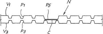
The result of said method is schematically illustrated in Fig. 7, and this figure has represented the cross section by the amplification of coiled material N on the orthogonal direction of material surface.P1, P3 represent respectively by corresponding first embossing units 301,303 and 305, the 307 first group of projection that forms on layer V1 and V3.P5 represents second group of projection that the protruding top 309P by the impression cylinder 309 of second embossing units 309 and 311 produces on layer V1.Layer V3 runs into projection P5 place at it and is extruded, and projection P3 is removed basically or reduced largely at least.Two-layer V1 and V3 are glued to together in the position of projection P5, and projection P5 is further more outstanding than projection P1, and adhesive is not assigned to projection P1 by distributor 315.
Under roller 313 has been capped more the situation of the material of plasticity, the outward appearance of final products as shown in figure 11, its middle level V3 outwards is out of shape in the position of projection P5.
Figure 12 represents the plan view by the part of the coiled material of described method production, and its visual angle is the side of layer V1.The bigger projection of representing with P5 forms the design (be flower pattern) of a decoration in illustrated embodiment, and background of adding some points of projection P1 formation.
Fig. 8 has represented another embodiment according to device of the present invention.In this embodiment, be provided with first embossing units that is used for layer V1, it comprises a pair of knurling rolls 401,403 with first embossing units, 301,303 equivalences.Roller 401 is by hard material, and for example steel is made, and has the many protruding top that is similar to protruding top 301P, and roller 403 is covered with plastic material.In this case, also can use the roller 401 and 403 that is formed from steel.
After this pair roller 401 and 403, second embossing units that is used for ground floor V1 is arranged.This second embossing units comprises an impression cylinder 409 that is equal to the impression cylinder 309 among Fig. 6, this impression cylinder 409 and first pressure roller, 411 mating reactions that are covered with plastic material.Impression cylinder 409 interacts with another impression cylinder 421, and the latter and impression cylinder 409 form a lamination roll gap.Another impression cylinder 421 has many protruding top 421P, and the size of protruding top 421P and density correspond essentially to the protruding top (seeing the enlarged drawing of Fig. 8 A) of knurling rolls 401.
To be similar to the mode of pressure roller 411, another impression cylinder 421 and second pressure roller, 423 mating reactions that are covered with plastic material, for example rubber.Impression cylinder 421 and pressure roller 423 have formed first embossing units that is used for second layer V3.
Adhesive means that is similar to the adhesive means 315 among Fig. 6 of label 415 expression, it and impression cylinder 409 mating reactions.
The roller 401 and 403 of ground floor coiled material V1 by first embossing units produces and has the first background embossing of first group of projection that density is the order of magnitude on every square centimeter on 10-100 protruding top.Material layer V1 embossing in this way, and enter second embossing units, the latter comprises pressure roller 411 and impression cylinder 409.Impression cylinder 409 has many protruding top 409P that are equal to the protruding top 309P of impression cylinder 309 shown in Figure 6.Second embossing units 409,411 has produced the second group of projection that forms decorative pattern on layer V1.
Second layer V3 is by being used for another embossing units of the second layer, and at this by the 421P embossing of protruding top, thereby on this layer V3, formed the one group of projection that constitutes background patterns.This embossing units is made of an impression cylinder 421 and pressure roller 423.
In the lamination gap between two impression cylinders 409,421, by the lamination effect that the pressure of protruding top 421P on the protruding top 409P of impression cylinder 409 by impression cylinder 421 carries out, two-layer V1 and V3 are joined together.The product of Huo Deing schematically shows with sectional view in Fig. 9 like this.In Fig. 9, P1 and P3 represent the projection of first group of projection producing by first embossing units 401,403 that is used for ground floor V1 respectively and the projection of first group of projection producing by embossing units 421,423 in the second layer.P5 represents to form second group of projection than big projection of decorative pattern, and this decorative pattern is produced by second embossing units 409,411 that is used for ground floor.When layer V1 looks, the outward appearance of product is still as shown in Figure 12.
Figure 10 schematically shows another embodiment according to apparatus of the present invention.Label 201 and 203 expressions are used for first embossing units of ground floor V1, this embossing units comprises a pair of knurling rolls, roller 201 is made by steel or hard material, and is provided with protruding top 201P (seeing shown in the view that Figure 10 A amplifies), and roller 203 is covered with the plasticity elastomeric material.The impression cylinder of label 205 and 207 expression rollers 305 a pair of and shown in Figure 6 and 307 equivalences.Roller 205 is made by steel or other hard materials, and is furnished with protruding top 205P (seeing the zoomed-in view of Fig. 6 B), and roller 207 is covered with elastic plastic material.Roller 205 and 207 has formed another embossing units that is used for the second layer.In this case, two first embossing units 201,203 can be made of the pair roller made from hard material that becomes with 205,207, and are provided with corresponding protruding top.
Second embossing units that is used for ground floor V1 comprises an impression cylinder 209.Many protruding top 209P that is provided with on this impression cylinder 209 and protruding top 409P and 309P are similar, and are positioned at after the embossing units 201,203 and 205,207 that is used for first and second layers of V1 and V3.Impression cylinder 209 and one first and second pressure roller 211 and 213 mating reactions, the latter is covered with elastic plastic material.
Ground floor V1 is embossed by corresponding embossing units 201,203, and has been set up the first group of projection P1 that forms background patterns; And second layer V3 in a similar fashion, embossed by corresponding embossing units 205,207, and be set up the corresponding first group of projection P3 that forms background patterns.
Embossed by this way layer V1 be second embossing units by being made of pressure roller 211 and impression cylinder 209 then, second group of projection P5 that the protruding top 209P of this impression cylinder 209 produces has than first group of height and elongation that projection P1 is bigger, and lower density.Protruding top 209P is by squeezing action, eliminated projection P1 in lamination area basically.
Be connected on layer V1 in the layer lamination roll gap of V3 between impression cylinder 209 and pressure roller 213, two-layer by adhesive and glued together at this.This adhesive is applied on the surface portion that is bearing in the layer V1 on the protruding top 209P by distributor 215.
Final product schematically shows with the sectional view that amplifies in Figure 11.Form contrast with product among Fig. 7, Figure 11 is illustrated in the embossing of layer V3 of the position of projection P5, and therefore also in the position of the protruding top 209P of cylinder 209, it is that tectal yield characteristic owing to pressure roller 213 produces.When layer V1 looks, the outer appearnce of product is similar to the product shown in Figure 12.If pressure roller 213 has harder surface, for example to make by steel or hard rubber, final product will have outward appearance shown in Figure 7.
Figure 13 has represented a variation of Fig. 6 schematic diagram.Wherein, identical or corresponding parts are denoted by like references.In this embodiment, knurling rolls 303 have been saved, and knurling rolls 301 and pressure roller 311 mating reactions.Roller 301 and 311 axis and the axis of impression cylinder 309 align in vertical plane.In this structure, saved a roller.Structure shown in Fig. 8 and 10 also can improve in a similar fashion.
Explanation as the front is clearly represented, has produced the decorative pattern that is formed by second group of projection P5, and has produced the first group of projection P1 that forms background patterns by different with it cylinders in all cases.As a result, for customed product, for example satisfy the needs of niche market and when replacing decorative pattern, do not need to construct the cylinder of a new complexity, the protruding top of this cylinder produces background patterns and produces decorative pattern.Replace this situation, change the impression cylinder (309,409 that produces second group of projection P5; 209) just enough, the roller that produces simultaneously background patterns on two-layer remains unchanged.By a kind of more favourable mode, protruding top 309P, 409P, 209P can be formed by interchangeable insert.These inserts can be loaded onto cylinder removably, and cylinder does not need to be replaced.Perhaps, cylinder 309,409,209 can have the outer roller sleeves that can replace, and corresponding protruding top is installed on roller sleeves.By this way, only need to replace outer sleeve and change the decorative pattern that on coiled material, forms by second group of projection P5.
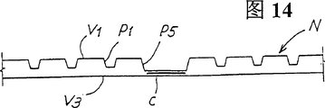
Figure 14 has represented the amplification sectional view by a coiled material, and this coiled material can be by the device production shown in one, and wherein, layer V3 is by the outside of corresponding first embossing units 305,307 or 421,423 or 205,207.By this way, layer V3 keeps smooth, and the adhesive C by a kind of colour, is connected to a layer V1 in the position of projection P5, to obtain a better decorative effect.
Should be appreciated that the example shown in the figure has only provided one of the present invention and put into practice size, form of the present invention and being provided with can change and not break away from the scope of invention spirit.About any reference number that in appended claims, occurs, its objective is for convenience of with reference to specification and accompanying drawing reading right claim, do not limit the protection domain that claims are put down in writing.
Claims (56)
1. method of producing embossed sheet, described embossed sheet comprises the two-layer at least coiled material that links together (V1, V2; V1, V3), comprise the steps:
(V1) carries out embossing to the ground floor coiled material, and this ground floor coiled material (V1) has been arranged in advance by first group of projection (P2; P102; P5) background patterns of Gou Chenging, thus second group of projection (P4 on this ground floor coiled material, produced; P104; P5), this second group of jut is stacked on the first group of projection that forms background patterns, and defines the decorative pattern that is made of the pattern that has large-size and less density with respect to background patterns;
By sizing material (C) with at least one second layer coiled material (V2; V3) be connected to described ground floor coiled material (V1);
It is characterized in that described sizing material (C) is applied to corresponding to described second group of projection (P4; P104; On the zone of at least a portion projection P5), at the first group of projection (P2 that forms described background patterns; P102; P1) on the complementary protuberance, described sheet material does not have sizing material basically.
2. method according to claim 1 is characterized in that, the described background patterns on the described ground floor coiled material (V1) be to ground floor (V1) embossing with before producing described decorative pattern, obtain by embossing in a row.
3. method according to claim 1 is characterized in that, to described second layer coiled material (V3) embossing, to produce thereon than first group of projection (P2; P204) have more the 3rd group of projection (P6 of large scale and less density; P106).
4. method according to claim 2 is characterized in that, to described second layer coiled material (V3) embossing, to produce thereon than first group of projection (P2; P204) have more the 3rd group of projection (P6 of large scale and less density; P106).
5. method according to claim 3 is characterized in that, second and the 3rd group of projection (P4, P6; P104 P106) has identical density, and one is inserted in another.
6. method according to claim 2 is characterized in that, by described ground floor (V1) is walked around and one first and second impression cylinder (1,3; 101; 103) one of mating reaction first pressure roller (5; 105) operation, and go up the described first group of projection of generation (P2 at described ground floor (V1); P102) and described second group of projection (P4; P104), described first and second impression cylinders (1,3; 101; 103) have first and second groups of protruding tops (1P, 3P respectively; 101P, 103P), second group of protruding top (3P; 103P) than first group of protruding top (1P; 101P) has bigger size and lower density.
7. method according to claim 6 is characterized in that, comprises at first pressure roller (5; 105) and with this first pressure roller (5; 105) second impression cylinder (3 of mating reaction; 103) (V1's described first and second layers between V2) links together.
8. method according to claim 6 is characterized in that, described second impression cylinder (3) produces described the 3rd group of projection (P6) with one second pressure roller (7) mating reaction to go up at the described second layer (V2).
9. method according to claim 7 is characterized in that, described second impression cylinder (3) produces described the 3rd group of projection (P6) with one second pressure roller (7) mating reaction to go up at the described second layer (V2).
10. according to each described method in the claim 3 to 9, it is characterized in that, with sizing material be applied to described the 3rd group of projection (P6) on the described second layer (V2) to small part, and by gluing with described two-layer (V1, V2) couple together, described the 3rd group of projection (P6) is corresponding to the projection of described second group of projection (P4).
11. according to each described method in the claim 3 to 9, it is characterized in that, by than the bigger embossing degree of depth of the embossing degree of depth of the second group of projection (P4) on ground floor (V1) to the described second layer (V2) embossing.
12. method according to claim 6, it is characterized in that, between described first impression cylinder (101) and described first pressure roller (105) to the downstream in the zone of described ground floor (V1) embossing, make the described second layer (V2) around described first pressure roller (105) operation, the described ground floor (V1) between described first pressure roller (105) and second impression cylinder (103) is gone up the described second layer (V2) embossing.
13. method according to claim 12 is characterized in that, round second impression cylinder (103) one second pressure roller (107) is set; Around described second pressure roller (107) a three-layer coil material (V3) is fed between this second pressure roller (107) and second impression cylinder (103), thereby go up generation the 4th group of projection (P108) at the 3rd layer (V3); First, second and the 3rd layer (V1, V2, V3) are laminated on together between second impression cylinder (103) and second pressure roller (107).
14. method according to claim 13, it is characterized in that, with sizing material (C) be applied to described second group of projection (P104) to the small part projection, and by make sizing material (C) towards the second layer (V2) migration by ground floor (V1) with described three layers of (V1, V2, V3) gluing.
15. according to each described method in the claim 3 to 5, it is characterized in that, produce described first group of projection (P2) by first impression cylinder (1 ') and pressure roller (5 ') thereof, produce second group of projection (P4) with another pressure roller (5) and one second impression cylinder (3), one the 3rd pressure roller (7) and this second impression cylinder (3) mating reaction, second impression cylinder and the 3rd pressure roller are gone up at the described second layer (V2) and are produced described the 3rd group of projection (P6).
16. method according to claim 1 is characterized in that, described second layer coiled material (V3) has been arranged the background patterns that is made of one group of projection (P3).
17. method according to claim 15 is characterized in that, the background patterns of described second layer coiled material (V3) is with before ground floor coiled material (V1) is connected, obtain by embossing in a row.
18. method according to claim 16 is characterized in that, the projection of the background patterns on described first and second layers (P1, P3) and the described decorative pattern on ground floor equivalent layer (V1, outstanding on same one side V3).
19. method according to claim 17 is characterized in that, the projection of the background patterns on described first and second layers (P1, P3) and the described decorative pattern on ground floor equivalent layer (V1, outstanding on same one side V3).
20. method according to claim 18, it is characterized in that, the projection that forms described decorative pattern has than the bigger height of projection that forms described background patterns, and described two-layer by gluing the linking together in position in the projection (P5) of described decorative pattern.
21., it is characterized in that described first and second layers are passed through corresponding first embossing units (301-303,305-307 according to each described method in the claim 16 to 20; 201-203,205-207) embossing respectively, thus go up the projection that produces the formation background patterns, the described then two-layer impression cylinder (209 of walking around at two-layer (V1, V3); 309) move, at this impression cylinder (209; 309) be provided with the protruding top (209P that is used for producing described decorative pattern at described ground floor (V1); 309P), and connect described two-layer.
22. method according to claim 21, it is characterized in that, described ground floor (V1) is in the pair of rolls (401 of one first embossing units, 403) according to described background patterns embossing, go up embossing at an impression cylinder (409) that is provided with the protruding top (409P) that is used to produce described decorative pattern then between; The described second layer (V3) embossing between another impression cylinder (421) and a pressure roller (423), described another impression cylinder being provided with are used for going up the protruding top (421P) that produces described background patterns at the described second layer (V3); And described two-layerly between described two impression cylinders (409,421), be joined together.
23., it is characterized in that described layer (V1, V3) links together by colored sizing material according to each described method in the claim 16 to 20.
24. an embossed layers die pressing product comprises two layers of coiled materials (V1, V2 at least; V1, V3), wherein: described ground floor coiled material (V1) has one by first group of projection (P2; P102; P1) background patterns of Gou Chenging; One by second group of projection (P4; P104; P5) decorative pattern of Gou Chenging is with after-applied and be stacked on the described background patterns described second group of projection (P4; P104; P5) have bigger size and less density with respect to first group of projection, described ground floor (V1) is connected to a second layer coiled material (V2 by sizing material (C); V3); Corresponding to described second group of projection (P4; P104; P5) apply described sizing material, form described first group of projection (P2 of described background patterns; P102; P1) there is not sizing material on basically.
25. embossed layers die pressing product according to claim 24 is characterized in that, described two-layer (V1 is V2) by colored sizing material and gluing.
26. embossed layers die pressing product according to claim 24 is characterized in that, and described second layer coiled material (V2, V3) embossed.
27. embossed layers die pressing product according to claim 25 is characterized in that, and described second layer coiled material (V2, V3) embossed.
28. embossed layers die pressing product according to claim 25 is characterized in that, the embossing of described second layer coiled material (V2) comprises the 3rd group of projection (P6; P106), the 3rd group of projection is with respect to described first group of projection (P1; P102) have bigger size and less density, wherein said first group of projection defines background patterns on described ground floor (V1).
29. embossed layers die pressing product according to claim 28 is characterized in that, described first group of projection (P2; P102) at described second group of projection (P4 of described ground floor (V1); The position of projection P104) is extruded.
30. embossed layers die pressing product according to claim 28 is characterized in that, described the 3rd group of projection (P6 on the described second layer (V2); P106) projection is inserted in the described second group of projection (P4 on the described ground floor (V1); The inboard of projection P104).
31. embossed layers die pressing product according to claim 29 is characterized in that, described the 3rd group of projection (P6 on the described second layer (V2); P106) projection is inserted in the described second group of projection (P4 on the described ground floor (V1); The inboard of projection P104).
32., it is characterized in that described the 3rd group of projection (P6 on the described second layer (V2) according to each described embossed layers die pressing product in the claim 28 to 31; The height of projection P106) is greater than the described second group of projection (P4 on described ground floor (V1); P104) projection.
33., it is characterized in that the 3rd group of projection (P6 on the described second layer (V2) according to each described embossed layers die pressing product in the claim 28 to 31; P106) projection to small part, described two-layer being glued to together.
34. according to each described embossed layers die pressing product in the claim 28 to 31, it is characterized in that, it comprises one the 3rd layer (V3), and described the 3rd layer of prominence in second group of projection (P104) of described ground floor (V1) is connected to first and second layers (V1, V2).
35. embossed layers die pressing product according to claim 34, it is characterized in that, described the 3rd layer (V3) is with the 4th group of projection (P108) embossing, described the 4th group of projection be provided with the described second layer (V2) on the identical pattern of projection of the 3rd group of projection (P106), but do not have the projection height of the 3rd group of projection (P106) on the described second layer (V2).
36. embossed layers die pressing product according to claim 34 is characterized in that, described the 3rd layer (V3) is glued to described ground floor (V1) described second group of projection (P104) to the small part projection.
37. embossed layers die pressing product according to claim 35 is characterized in that, described the 3rd layer (V3) is glued to described ground floor (V1) described second group of projection (P104) to the small part projection.
38. embossed layers die pressing product according to claim 26, it is characterized in that, described the 3rd layer (V3) comprises at least one background embossing, and the latter is made of many 3rd group of projections (P3), and the 3rd group of projection has less size and bigger density with respect to described decorative pattern.
39., it is characterized in that the projection of each layer is outstanding from the surface in the face of the equivalent layer of sheet material inside according to the described embossed layers die pressing product of claim 38.
40., it is characterized in that described the 3rd group of projection (P3) in the described second layer (V3) is extruded in the position of the projection (P5) of second group of projection of the described ground floor that forms described decorative pattern according to the described embossed layers die pressing product of claim 38.
41., it is characterized in that described the 3rd group of projection (P3) in the described second layer (V3) is extruded in the position of the projection (P5) of second group of projection of the described ground floor that forms described decorative pattern according to the described embossed layers die pressing product of claim 39.
42. according to the described embossed layers die pressing product of claim 40, it is characterized in that, the described second layer (V3) forms the place of the projection (P5) of described decorative pattern in running into ground floor (V1), have with in the face of the projection on the surperficial facing surfaces of ground floor (V1).
43. a production is by two-layer at least (V1, V2; V1, the V3) device of the coiled material of Gou Chenging (N) comprising:
One first embossing units, it is used for going up generation by first group of projection (P2 at described at least ground floor (V1); P102; P1) background patterns of Gou Chenging;
One second embossing units, it is used for going up generation by second group of projection (P4 at described ground floor (V1); P104; P1) decorative pattern of Gou Chenging, this decorative pattern partly is stacked on the described background patterns, wherein said second group of projection (P4; P104; P1) with respect to described first group of projection (P2; P102; P1) has bigger size and less density;
A sizing material bringing device, it is used to apply sizing material and a second layer is connected in described ground floor;
It is characterized in that described sizing material bringing device is applied to described second group of projection (P4 with described sizing material; P104; P5) on the projection, but be not applied on the first group of projection that forms described background patterns, this sizing material bringing device cooperates with described second embossing units.
44. according to the described device of claim 43, it is characterized in that, as one first pressure roller (5 of the public pressure roller of described first and second embossing units; 105) with one first and second impression cylinder (1,3; 101; 103) mating reaction, this first and second impression cylinder (1,3; 101; 103) carrying separately protruding top (1P, 3P respectively at its cylinder surface; 101P, 103P), be used for go up producing described first and second groups of projections at described ground floor (V1).
45., it is characterized in that first impression cylinder (1 according to the described device of claim 44; 101) protruding top (1P; 101P) than second impression cylinder (3; 103) protruding top (3P; 103P) have bigger density and less size.
46., it is characterized in that it comprises one and second impression cylinder (3 according to the described device of claim 45; 103) second pressure roller (7 of mating reaction; 107).
47. according to the described device of claim 43, it is characterized in that, described first embossing units comprises one first pressure roller (5 ') with one first impression cylinder (1 ') mating reaction, and described second embossing units comprises one second impression cylinder (3) with second and the 3rd pressure roller (5,7) mating reaction.
48., it is characterized in that it comprises according to the described device of claim 43:
One another embossing units (305,307; 421,423; 205,207), it is used for a second layer (V3), and described first embossing units and described another embossing units have produced one by first group of projection (P1 in the described ground floor and the described second layer; P3) background patterns that is constituted.
49., it is characterized in that be used to connect described two-layer device and connect described two-layerly at the projection position place of second group of projection, described second group of projection forms described decorative pattern according to the described device of claim 48.
50. according to claim 48 or 49 described devices, it is characterized in that, described be used for first and second layers (V1, V3) first embossing units and described another embossing units that go up to produce described background patterns respectively comprises a pair of knurling rolls, one of them knurling rolls (1,5; 201,205) be provided with protruding top (1P, 5P; 201P, 205P), and another knurling rolls (3,7; 203,207) be provided with a plastic surface.
51. according to claim 48 or 49 described devices, it is characterized in that, be used to connect the impression cylinder (9 that described two-layer described device comprises second embossing units; 209) and one the coupling roller (13; 213), described impression cylinder (9; 209) be provided with the protruding top (9P that is used to produce the second group of projection that forms described decorative pattern; 209P).
52., it is characterized in that described coupling roller (13) has the periphery of substantially rigid according to the described device of claim 51.
53. according to claim 48 or 49 described devices, it is characterized in that, described first embossing units that is used for ground floor (V1) comprises a pair of knurling rolls (401,403), described second embossing units comprises an impression cylinder (409), this impression cylinder being provided with is used to produce the protruding top (409P) of the second group of projection (P5) that forms described decorative pattern, and with a pressure roller (411) mating reaction; Another embossing units (421,423) that is used for the second layer (V3) comprises another impression cylinder (421), and this impression cylinder (421) is being provided with protruding top (421P), and with pressure roller (a 423) mating reaction with plastic surface.
54., it is characterized in that the described device that is used to connect described layer is by described two impression cylinders (409,421) formation according to the described device of claim 53, the latter forms a laminating area betwixt, two impression cylinders act on each other in laminating area.
55., it is characterized in that described second embossing units has an impression cylinder (309 according to each described device in the claim 43 to 49; 409; 209), the latter have interchangeable protruding top (309P, 409P, 209P).
56. according to the described device of claim 48, it is characterized in that, first embossing units (301 that is used for ground floor (V1), 303) comprise a roller (301), this roller (301) is provided with protruding top (301P), and with pressure roller (a 311) mating reaction that is covered with plastic material, the latter and second impression cylinder (309; 311) a impression cylinder (309) interacts.
Applications Claiming Priority (4)
| Application Number | Priority Date | Filing Date | Title |
|---|---|---|---|
| ITFI98A46 | 1998-03-02 | ||
| IT98FI000046A ITFI980046A1 (en) | 1998-03-02 | 1998-03-02 | METHOD AND DEVICE FOR MULTIPLE EMBOSSING OF RIBBON-SHAPED MATERIALS IN SEVERAL PLY AND RELATED PRODUCT OBTAINED. |
| ITFI980139 ITFI980139A1 (en) | 1998-06-10 | 1998-06-10 | METHOD AND DEVICE FOR THE PRODUCTION OF AN EMBOSSED MATERIAL IN SEVERAL VEHICLES AND RELATED PRODUCT SO OBTAINED |
| ITFI98A000139 | 1998-06-10 |
Publications (2)
| Publication Number | Publication Date |
|---|---|
| CN1291938A CN1291938A (en) | 2001-04-18 |
| CN1180932C true CN1180932C (en) | 2004-12-22 |
Family
ID=26330579
Family Applications (1)
| Application Number | Title | Priority Date | Filing Date |
|---|---|---|---|
| CNB998035610A Expired - Fee Related CN1180932C (en) | 1998-03-02 | 1999-03-01 | Method and device for producing embossed web material and product made in this way |
Country Status (14)
| Country | Link |
|---|---|
| US (2) | US6755928B1 (en) |
| EP (1) | EP1075387B1 (en) |
| JP (1) | JP2002505207A (en) |
| KR (1) | KR100399733B1 (en) |
| CN (1) | CN1180932C (en) |
| AT (1) | ATE254999T1 (en) |
| AU (1) | AU3273499A (en) |
| BR (1) | BR9908459A (en) |
| CA (1) | CA2320127C (en) |
| DE (1) | DE69913122T2 (en) |
| ES (1) | ES2211136T3 (en) |
| IL (1) | IL138118A (en) |
| PL (1) | PL188926B1 (en) |
| WO (1) | WO1999044814A1 (en) |
Families Citing this family (104)
| Publication number | Priority date | Publication date | Assignee | Title |
|---|---|---|---|---|
| GB2376436B (en) * | 2001-06-15 | 2004-07-07 | Sca Hygiene Prod Gmbh | Multi-ply tissue paper product and method for producing same |
| IT1312535B1 (en) * | 1999-04-16 | 2002-04-22 | Cartoinvest Societa Finanziari | STRUCTURE OF PAPER PRODUCT PARTICULARLY FOR HOUSEHOLD AND SANITARY USE AND PROCEDURE FOR ITS REALIZATION. |
| IT1307887B1 (en) * | 1999-06-18 | 2001-11-19 | Perini Fabio Spa | EMBOSSING METHOD AND DEVICE FOR THE PRODUCTION OF MULTI-LEVEL STRUCTURAL MATERIALS, AND PRODUCT SO OBTAINED. |
| IT246987Y1 (en) * | 1999-08-06 | 2002-05-02 | C M G Costruzioni Meccaniche G | TRANSFORMABLE MACHINE FOR SURFACE PAPER PROCESSING |
| CA2324786C (en) | 1999-11-01 | 2014-02-25 | Fort James Corporation | Multi-ply absorbent paper product having impressed pattern |
| DE19960658A1 (en) | 1999-12-15 | 2001-06-28 | A & E Ungricht Gmbh & Co Kg | Embossing patterns on tissue webs uses a pair of rollers with an engraved roller bearing against a counter roller, using a secondary pattern with local pressure points to reduce wear on the counter roller |
| US6733866B2 (en) | 2001-06-15 | 2004-05-11 | Sca Hygiene Products Gmbh | Multi-ply tissue paper product and method for producing same |
| GB2380447B (en) * | 2001-10-02 | 2004-01-14 | Sca Hygiene Prod Gmbh | Device and method for applying a spot embossing pattern to a web of multi-ply tissue paper |
| US6863107B2 (en) | 2001-10-02 | 2005-03-08 | Sca Hygiene Products Gmbh | Device for applying a spot embossing pattern to a web of multi-ply tissue paper |
| ITFI20010223A1 (en) | 2001-11-26 | 2003-05-26 | Perini Fabio Spa | EMBOSSING CYLINDER WITH INTERCHANGEABLE SHIRT AND WITH FRONT SHIRT LOCKING SYSTEM, AND EMBOSSING GROUP INCLUDING SAID |
| BR0214418B1 (en) | 2001-11-26 | 2011-07-26 | rotary cylinder for processing a fabric type material, interchangeable cylinder sleeve, glove manufacturing method, and stamping unit. | |
| ITMI20020361A1 (en) * | 2002-02-22 | 2003-08-22 | Linder & Perla S P A | METHOD FOR THE CREATION OF OPTIMIZED FOUR-SHEET SANITARY PAPER AND RELATED EQUIPMENT |
| US7101437B2 (en) * | 2002-03-15 | 2006-09-05 | The Procter & Gamble Company | Elements for embossing and adhesive application |
| ITFI20020053A1 (en) | 2002-03-29 | 2003-09-29 | Perini Fabio Spa | METHOD AND DEVICE FOR THE PRODUCTION OF EMBOSSED AND MANUFACTURED MATERIAL OBTAINED WITH THIS METHOD |
| SE0201088D0 (en) * | 2002-04-09 | 2002-04-09 | Sca Hygiene Prod Ab | Method for producing a multi-ply web of flexible material, such as paper and nonwoven, and multi-ply material produced by the method |
| US7063766B2 (en) | 2002-04-09 | 2006-06-20 | Sca Hygiene Products Ab | Method for producing a multi-ply web of flexible material, such as paper and nonwoven, and multi-ply material produced by the method |
| ITFI20030015A1 (en) * | 2003-01-17 | 2004-07-18 | Fabio Perini | DEVICE AND METHOD TO CARRY OUT THE JOINT OF PAPER VEILS |
| ES2245162B1 (en) * | 2003-03-04 | 2007-02-16 | Videcart S.A | GOAMED LAMINAR ELEMENT, PROCEDURE AND MACHINE FOR MANUFACTURING. |
| ITFI20030208A1 (en) * | 2003-08-01 | 2005-02-02 | Perini Fabio Spa | METHOD AND DEVICE FOR THE PRODUCTION OF A PRODUCT |
| US7314663B2 (en) * | 2003-09-29 | 2008-01-01 | The Procter + Gamble Company | Embossed multi-ply fibrous structure product and process for making same |
| US7374638B2 (en) * | 2003-09-29 | 2008-05-20 | The Procter & Gamble Company | High bulk strong absorbent single-ply tissue-towel paper product |
| US20050247397A1 (en) * | 2003-09-29 | 2005-11-10 | The Procter & Gamble Company | Process for producing embossed products |
| FR2860527B1 (en) * | 2003-10-02 | 2006-01-27 | Georgia Pacific France | ABSORBENT PAPER SHEET |
| EP1525977B1 (en) * | 2003-10-24 | 2012-06-20 | SCA Hygiene Products GmbH | Apparatus and method for embossing a multi-ply paper product |
| ITFI20040032A1 (en) * | 2004-02-13 | 2004-05-13 | Perini Fabio Spa | METHOD AND DEVICE EMBOSSER AND LAMINATOR FOR THE PRODUCTION OF MULTI-SPEED PRODUCTS AND RELATED PRODUCT |
| CN101124363A (en) * | 2004-02-17 | 2008-02-13 | 宝洁公司 | Deep-nested embossed paper products |
| ITFI20040053A1 (en) * | 2004-03-04 | 2004-06-04 | Perini Fabio Spa | MULTI-SPEED PRODUCT IN PAPER OR SIMILAR, METHOD FOR ITS PRODUCTION AND RELATED PLANT |
| ITMI20040675A1 (en) * | 2004-04-02 | 2004-07-02 | Sca Hygiene Prod Ab | APPARATUS AND PROCEDURE FOR THE REALIZATION OF A MULTI-SPEED PRODUCT IN ABSORBENT PAPER AND PRODUCTS SO OBTAINED |
| ITFI20040102A1 (en) * | 2004-04-29 | 2004-07-29 | Guglielmo Biagiotti | METHOD AND DEVICE FOR THE PRODUCTION OF TISSUE PAPER |
| ITFI20040107A1 (en) | 2004-05-05 | 2004-08-05 | Perini Fabio Spa | INTERCHANGEABLE SHIRT ROLLER FOR EMBOSSING GROUPS AND EMBOSSING GROUP INCLUDING SUCH ROLLER |
| US7413629B2 (en) * | 2004-05-21 | 2008-08-19 | The Procter & Gamble Company | Process for producing deep-nested embossed paper products |
| US7435313B2 (en) * | 2004-05-21 | 2008-10-14 | The Procter & Gamble Company | Process for producing deep-nested embossed paper products |
| ITFI20040143A1 (en) | 2004-06-25 | 2004-09-25 | Perini Fabio Spa | AN ANALOG, PRINTED AND EMBOSSED PAPER OR PRODUCT NAPKIN |
| US7799169B2 (en) | 2004-09-01 | 2010-09-21 | Georgia-Pacific Consumer Products Lp | Multi-ply paper product with moisture strike through resistance and method of making the same |
| ITFI20040202A1 (en) * | 2004-09-30 | 2004-12-30 | Perini Fabio Spa | INTERCHANGEABLE SHIRT FOR EMBOSSING ROLLERS OR SIMILAR, METHOD FOR ITS REALIZATION, AND ROLLER INCLUDING THE SHIRT |
| JP4827409B2 (en) * | 2004-12-28 | 2011-11-30 | 大王製紙株式会社 | Embossed sheet manufacturing method and manufacturing equipment |
| US20060157381A1 (en) * | 2005-01-20 | 2006-07-20 | Adams James T | Component carrier and method for making |
| ITFI20050032A1 (en) | 2005-03-01 | 2006-09-02 | Perini Fabio Spa | METHOD AND PROVISION FOR THE JOINT OF PAPER SAILS |
| US7597777B2 (en) * | 2005-09-09 | 2009-10-06 | The Procter & Gamble Company | Process for high engagement embossing on substrate having non-uniform stretch characteristics |
| MX2008003088A (en) * | 2005-09-21 | 2008-03-19 | Procter & Gamble | Absorbent paper product having high definition embossments. |
| ITFI20050218A1 (en) * | 2005-10-20 | 2007-04-21 | Guglielmo Biagiotti | IMPROVEMENT OF METHODS AND DEVICES FOR THE PRODUCTION OF TISSUE PAPERS AND PAPER VEIL FROM THESE DERIVATIVES |
| DE102006010709A1 (en) | 2006-03-08 | 2007-09-13 | Metsä Tissue Oyj | Embossing device for at least two-ply surface products such as toilet paper, handkerchiefs o. |
| ITFI20060072A1 (en) * | 2006-03-15 | 2007-09-16 | Perini Fabio Spa | EMBOSSING ROLLER AND ITS PROCEDURE FOR ITS PRODUCTION |
| DE102007006437A1 (en) * | 2006-06-26 | 2008-01-03 | Fleissner Gmbh | Calender roll for embossing and / or compacting textiles |
| ITBO20060553A1 (en) * | 2006-07-25 | 2008-01-26 | Andrea Bernacchi | METHOD AND EQUIPMENT FOR THE PRODUCTION OF ROLLS FOR MEDICAL BEDS. |
| WO2008034160A1 (en) * | 2006-09-21 | 2008-03-27 | Senevens International Ltd | Apparatus and method of manufacturing a tape for disposable diapers |
| ITFI20060245A1 (en) | 2006-10-11 | 2008-04-12 | Delicarta Spa | A MATERIAL IN PAPER WITH HIGH DETERGENT CHARACTERISTICS AND METHOD FOR ITS PRODUCTION |
| WO2008069147A1 (en) * | 2006-11-30 | 2008-06-12 | Daio Paper Corporation | Kitchen papers |
| JP4545767B2 (en) * | 2007-02-28 | 2010-09-15 | 大王製紙株式会社 | Kitchen paper |
| WO2008071210A1 (en) * | 2006-12-13 | 2008-06-19 | Sca Hygiene Products Gmbh | Method for manufacturing a hygiene product, apparatus for manufacturing a hygiene product and hygiene product |
| ITFI20070048A1 (en) | 2007-02-27 | 2008-08-28 | Perini Fabio Spa | MULTI-FUNCTION EMBOSS GROUP |
| US7866904B2 (en) * | 2007-03-06 | 2011-01-11 | Datacard Corporation | Desktop card printer with indent printing apparatus and method of printing |
| ITFI20070163A1 (en) | 2007-07-18 | 2009-01-19 | Perini Fabio Spa | "EMBOSSED PAPER MATERIAL, METHOD AND DEVICE FOR ITS PRODUCTION" |
| KR100821284B1 (en) | 2007-08-21 | 2008-04-11 | 주식회사 아이티씨 | Manufacturing equipment of toilet roll formed plural embossing pattern |
| US20090057950A1 (en) * | 2007-09-05 | 2009-03-05 | George Vincent Wegele | Method for converting a multi-ply paper product |
| US7942995B2 (en) | 2007-09-05 | 2011-05-17 | The Procter & Gamble Company | Method for converting a multi-ply paper product |
| ITFI20080038A1 (en) * | 2008-02-27 | 2009-08-28 | Delicarta Spa | "MATERIAL PLURIVELO IN EMBOSSED PAPER AND MACHINE FOR ITS PRODUCTION" |
| FR2928383B1 (en) | 2008-03-06 | 2010-12-31 | Georgia Pacific France | WAFER SHEET COMPRISING A PLY IN WATER SOLUBLE MATERIAL AND METHOD FOR PRODUCING SUCH SHEET |
| ITFI20080229A1 (en) * | 2008-11-25 | 2010-05-26 | Delicarta Spa | "EMBOSSER-LAMINATOR UNIT AND EMBOSSING METHOD" |
| US8920905B2 (en) * | 2008-12-09 | 2014-12-30 | Sca Hygiene Products Ab | Fibrous product with a rastered embossing and method for producing same |
| JP2010148803A (en) * | 2008-12-26 | 2010-07-08 | Oji Nepia Co Ltd | Rolled sanitary paper |
| USD632896S1 (en) | 2009-03-10 | 2011-02-22 | The Procter & Gamble Company | Paper product |
| USD640473S1 (en) | 2009-03-10 | 2011-06-28 | The Procter & Gamble Company | Paper product |
| IT1394506B1 (en) * | 2009-06-08 | 2012-07-05 | Delicarta Spa | EMBOSSED PLURIVEL CELLULOSE MATERIAL |
| EP2480406B1 (en) * | 2009-09-22 | 2014-09-10 | SCA Hygiene Products AB | Fibrous product and method and device for manufacturing such a fibrous product |
| IT1399181B1 (en) * | 2010-01-28 | 2013-04-11 | Ind Cartarie Tronchetti Spa | PRODUCED IN PAPER WITH THREE OR MORE SAILS AND METHOD FOR ITS PRODUCTION |
| CN101824720A (en) * | 2010-05-21 | 2010-09-08 | 全利机械股份有限公司 | Fiber-product embossing device |
| US9067357B2 (en) | 2010-09-10 | 2015-06-30 | The Procter & Gamble Company | Method for deforming a web |
| EP2686164B1 (en) * | 2011-03-15 | 2016-04-27 | SCA Hygiene Products AB | Fibrous product and method for manufacturing such a fibrous product |
| US20120276238A1 (en) * | 2011-04-26 | 2012-11-01 | John Brian Strube | Apparatus for Deforming a Web |
| US8657596B2 (en) | 2011-04-26 | 2014-02-25 | The Procter & Gamble Company | Method and apparatus for deforming a web |
| FR2976473B1 (en) | 2011-06-15 | 2013-07-12 | Georgia Pacific France | ABSORBENT PAPER ROLL WITH LOW DIMENSIONS |
| ITFI20110135A1 (en) * | 2011-07-07 | 2013-01-08 | Futura Spa | DEVICE AND METHOD FOR THE MANUFACTURING OF MATERIAL CARATCEO NASTRIFORME. |
| CN102744918A (en) * | 2011-10-13 | 2012-10-24 | 金红叶纸业集团有限公司 | Compression roller, processing device, processing method and life paper and facial tissue units |
| CN102525323B (en) * | 2012-01-06 | 2014-01-29 | 金红叶纸业集团有限公司 | Daily paper |
| CN102873913B (en) * | 2012-08-27 | 2015-09-02 | 金红叶纸业集团有限公司 | The laminating method of multi-ply paper product and this multi-ply paper product |
| CN102862327B (en) * | 2012-09-19 | 2013-12-11 | 金红叶纸业集团有限公司 | Production process for multilayer paper |
| ITFI20130112A1 (en) | 2013-05-14 | 2014-11-15 | Perini Engraving S R L | EMBOSSING ROLLER, EMBOSSING GROUP INCLUDING SUCH ROLLER, EMBOSSING METHOD AND PRODUCT OBTAINED |
| EP2805801B1 (en) * | 2013-05-24 | 2020-10-21 | Faurecia Interieur Industrie | Method for processing a veneer |
| US20150354142A1 (en) * | 2014-06-09 | 2015-12-10 | Gambini International S.A. | Multilayer sheet |
| ES2690747T3 (en) | 2014-08-29 | 2018-11-22 | Sofidel S.P.A. | Stamped multilayer cellulose product and media for its production |
| DE102014013414A1 (en) * | 2014-09-16 | 2016-03-17 | Metsä Tissue Oyj | Process for the production of at least three-ply surface products |
| US10378151B2 (en) | 2014-12-01 | 2019-08-13 | Kikuo Yamada | Method of manufacturing paper sheet |
| KR102313886B1 (en) * | 2015-04-30 | 2021-10-20 | 킴벌리-클라크 월드와이드, 인크. | Improved embossed and perforated laminates for absorbent articles and the like |
| CN106264275A (en) * | 2015-06-04 | 2017-01-04 | 金红叶纸业集团有限公司 | One way of life paper using and raging system thereof |
| CN106313642A (en) * | 2015-06-30 | 2017-01-11 | 永丰余消费品实业股份有限公司 | Paper wood manufacturing assembly, paper wood structure and manufacturing method of paper wood structure |
| CN108349190A (en) * | 2015-10-29 | 2018-07-31 | 利乐拉瓦尔集团及财务有限公司 | Manufacture the method and apparatus and packaging material of decorated package |
| DE102015014515A1 (en) * | 2015-11-11 | 2017-05-11 | Dräger Safety AG & Co. KGaA | Electrolyte conductor, method for producing an electrolyte conductor and an electrochemical gas sensor and a gas meter with such |
| JP6685801B2 (en) * | 2016-03-31 | 2020-04-22 | 大王製紙株式会社 | Kitchen paper |
| IT201600086446A1 (en) * | 2016-08-22 | 2018-02-22 | Universal Tissue Tech S R L | DEVICE AND EMBOSSING METHOD |
| JP6461448B1 (en) * | 2017-03-02 | 2019-01-30 | 大王製紙株式会社 | Sanitary tissue paper |
| JP6501988B2 (en) * | 2017-03-02 | 2019-04-17 | 大王製紙株式会社 | Sanitary thin paper |
| JP6461449B1 (en) * | 2017-03-02 | 2019-01-30 | 大王製紙株式会社 | Sanitary tissue paper |
| EP3415306A1 (en) | 2017-06-14 | 2018-12-19 | Boegli-Gravures S.A. | Method and embossing structure using high density pressure for creating shadowed or curved highly reflective areas on rotationally embossed foils |
| CN108127944A (en) * | 2017-12-25 | 2018-06-08 | 昆山市硕鸿电子材料有限公司 | A kind of preparation method of patterned silica gel coiled material |
| KR102381024B1 (en) | 2018-10-31 | 2022-04-01 | 킴벌리-클라크 월드와이드, 인크. | embossed multi-ply tissue product |
| KR102122498B1 (en) * | 2019-09-26 | 2020-06-12 | 남슬기 | manufacturing method of wallpaper with improved surface embossing |
| BR112022005476A2 (en) | 2019-09-27 | 2022-06-14 | Koerber Tissue S P A | Method and machine for producing multi-layer cellulose mat material, and material produced |
| MX2022009718A (en) * | 2020-03-05 | 2022-09-09 | Kimberly Clark Co | Embossed multi-ply tissue products. |
| EP4087726A1 (en) | 2020-04-10 | 2022-11-16 | Körber Tissue S.p.A. | Method and device for heating an embossing roller in an embossing-laminating device |
| JP7345443B2 (en) * | 2020-08-21 | 2023-09-15 | 大王製紙株式会社 | Household tissue paper and method for producing household tissue paper |
| IT202100017675A1 (en) | 2021-07-05 | 2023-01-05 | Koerber Tissue S P A | EMBOSSING DEVICE WITH AT LEAST ONE HEATED EMBOSSING ROLLER, AND METHOD |
| IT202100019499A1 (en) | 2021-07-22 | 2023-01-22 | Koerber Tissue S P A | A MULTIPLE ROLLER EMBOSSER AND METHOD |
| WO2023104741A1 (en) | 2021-12-07 | 2023-06-15 | Körber Tissue S.p.A. | Embossing device for embossing a cellulose web material and related method |
Family Cites Families (22)
| Publication number | Priority date | Publication date | Assignee | Title |
|---|---|---|---|---|
| US3414459A (en) | 1965-02-01 | 1968-12-03 | Procter & Gamble | Compressible laminated paper structure |
| US3867225A (en) * | 1969-01-23 | 1975-02-18 | Paper Converting Machine Co | Method for producing laminated embossed webs |
| US3556907A (en) * | 1969-01-23 | 1971-01-19 | Paper Converting Machine Co | Machine for producing laminated embossed webs |
| US3672950A (en) * | 1970-01-12 | 1972-06-27 | Int Paper Co | Adhesively laminated cellulosic product |
| US3684641A (en) * | 1970-11-10 | 1972-08-15 | Int Paper Co | Laminated product bonded with colored adhesive |
| US3694300A (en) | 1971-08-27 | 1972-09-26 | Paper Converting Machine Co | Base product for textile replacement and method of producing the same |
| US3961119A (en) | 1973-03-15 | 1976-06-01 | Kimberly-Clark Corporation | Embossed paper toweling and method of production |
| US4307141A (en) * | 1978-10-10 | 1981-12-22 | American Can Company | Multi-ply fibrous sheet structure |
| US4320162A (en) | 1980-05-15 | 1982-03-16 | American Can Company | Multi-ply fibrous sheet structure and its manufacture |
| FR2604734B1 (en) | 1986-10-02 | 1989-01-06 | Beghin Say Sa | ABSORBENT LAMINATE SHEET |
| IT1225324B (en) | 1988-11-23 | 1990-11-06 | Perini Finanziaria Spa | PAPER PROCESSING MACHINE WITH COOPERATING EMBOSSING CYLINDERS FOR POINT-TO-POINT COUPLING OF TWO PAPER BELTS EMBOSSED BY THEM |
| US5091032A (en) | 1989-07-10 | 1992-02-25 | James River Corporation Of Virginia | Multi-nip high-speed paper converting |
| FR2653793B1 (en) | 1989-10-30 | 1992-01-03 | Kaysersberg Sa | |
| FR2684598B1 (en) | 1991-12-09 | 1995-04-07 | Kaysersberg Sa | METHOD FOR MANUFACTURING LAMINATED EMBOSSED SHEETS. MACHINE FOR ITS IMPLEMENTATION. |
| FR2700496B1 (en) * | 1993-01-15 | 1995-02-17 | Kaysersberg Sa | Method of embossing a sheet with one or more plies, sheet of embossed paper. |
| FR2707311B1 (en) * | 1993-07-09 | 1995-09-08 | Kaysersberg Sa | Multilayer embossed papers, device and procedure for their preparation. |
| FR2721251B1 (en) * | 1994-06-17 | 1996-07-26 | Kaysersberg Sa | Multilayer sheet of absorbent paper, process for its production |
| FR2728152B1 (en) | 1994-12-16 | 1997-01-24 | Kaysersberg Sa | COMBINED EMBOSSED ABSORBENT PAPER |
| IT1278801B1 (en) | 1995-12-05 | 1997-11-28 | Perini Fabio Spa | EMBOSSING-LAMINATOR GROUP FOR GLUING EMBOSSED VEILS, RELATIVE METHOD AND PRODUCT OBTAINED |
| IT1278803B1 (en) | 1995-12-05 | 1997-11-28 | Perini Fabio Spa | EMBOSSING-LAMINATOR GROUP, WITH NON-TIMED EMBOSSING CYLINDERS AND RELATIVE EMBOSSING METHOD |
| IT1278802B1 (en) | 1995-12-05 | 1997-11-28 | Perini Fabio Spa | EMBOSSING-LAMINATOR GROUP, WITH DISTRIBUTED CONTACT CYLINDERS AND RELATIVE EMBOSSING METHOD |
| ES2205228T3 (en) * | 1996-05-23 | 2004-05-01 | THE PROCTER & GAMBLE COMPANY | TISU PAPER OF MULTIPLE LAYERS WITH CONTINUOUS NETWORK ZONES. |
-
1999
- 1999-03-01 CN CNB998035610A patent/CN1180932C/en not_active Expired - Fee Related
- 1999-03-01 CA CA002320127A patent/CA2320127C/en not_active Expired - Fee Related
- 1999-03-01 IL IL13811899A patent/IL138118A/en not_active IP Right Cessation
- 1999-03-01 US US09/601,842 patent/US6755928B1/en not_active Expired - Fee Related
- 1999-03-01 ES ES99937900T patent/ES2211136T3/en not_active Expired - Lifetime
- 1999-03-01 AT AT99937900T patent/ATE254999T1/en not_active IP Right Cessation
- 1999-03-01 JP JP2000534392A patent/JP2002505207A/en active Pending
- 1999-03-01 KR KR10-2000-7009690A patent/KR100399733B1/en not_active IP Right Cessation
- 1999-03-01 AU AU32734/99A patent/AU3273499A/en not_active Abandoned
- 1999-03-01 WO PCT/IT1999/000051 patent/WO1999044814A1/en active IP Right Grant
- 1999-03-01 PL PL99342709A patent/PL188926B1/en unknown
- 1999-03-01 DE DE69913122T patent/DE69913122T2/en not_active Expired - Lifetime
- 1999-03-01 BR BR9908459-7A patent/BR9908459A/en not_active IP Right Cessation
- 1999-03-01 EP EP99937900A patent/EP1075387B1/en not_active Expired - Lifetime
-
2004
- 2004-04-23 US US10/830,082 patent/US7291379B2/en not_active Expired - Fee Related
Also Published As
| Publication number | Publication date |
|---|---|
| IL138118A0 (en) | 2001-10-31 |
| EP1075387B1 (en) | 2003-11-26 |
| US7291379B2 (en) | 2007-11-06 |
| US6755928B1 (en) | 2004-06-29 |
| CN1291938A (en) | 2001-04-18 |
| AU3273499A (en) | 1999-09-20 |
| KR20010041520A (en) | 2001-05-25 |
| IL138118A (en) | 2004-12-15 |
| KR100399733B1 (en) | 2003-09-29 |
| JP2002505207A (en) | 2002-02-19 |
| PL188926B1 (en) | 2005-05-31 |
| ES2211136T3 (en) | 2004-07-01 |
| EP1075387A1 (en) | 2001-02-14 |
| CA2320127A1 (en) | 1999-09-10 |
| ATE254999T1 (en) | 2003-12-15 |
| WO1999044814A1 (en) | 1999-09-10 |
| BR9908459A (en) | 2000-11-14 |
| US20040247836A1 (en) | 2004-12-09 |
| PL342709A1 (en) | 2001-07-02 |
| DE69913122T2 (en) | 2004-05-27 |
| DE69913122D1 (en) | 2004-01-08 |
| CA2320127C (en) | 2007-11-20 |
Similar Documents
| Publication | Publication Date | Title |
|---|---|---|
| CN1180932C (en) | Method and device for producing embossed web material and product made in this way | |
| CN1139693C (en) | Embossed multiply paper and process for producing same | |
| CN1159496C (en) | Embossed multiply paper and process for producing same | |
| CN1918001A (en) | Embossing and laminating method and device for producing multi-ply web products and relative product | |
| CN1288411A (en) | Embossing and laminating device for web material | |
| US8974892B2 (en) | Multi-ply paper product or the like, method for the production thereof and relative system | |
| CN102256805A (en) | Coated panel and method for manufacturing such panel | |
| CN100351073C (en) | Method and device for producing a multi-ply web of flexible material, such as paper and nonwoven, and multi-ply material produced by the method | |
| US6780270B2 (en) | Method and device for web for embossing and printing a web of flexible material, such as paper and nonwoven, and a web material produced by the method | |
| CN2715982Y (en) | Gluing and embossing device used for toilet paper rewinding machine | |
| CN100349730C (en) | Method and device for producing a multi-ply web of flexible material, such as paper and nonwoven, and multi-ply material produced by the method | |
| CN103648761B (en) | Apparatus and process for the production of paper web material. | |
| EP2353859B1 (en) | Paper product with three or more plies and method for manufacturing it | |
| EP2191959B1 (en) | Embossing-laminating unit and embossing method | |
| CN1729097A (en) | Method and device for producing a multi-ply printed web of flexible material, such as paper and nonwoven, and multi-ply material produced by the method | |
| EP3802098A1 (en) | Method and machine for embossing and calending tissue paper and resulting product | |
| US20060243383A1 (en) | Method and device to produce and embossed and printed product and product thereby obtained | |
| US7153385B2 (en) | Method and device for producing a multi-ply printed web of flexible material, such as paper and nonwoven, and multi-ply material produced by the method | |
| EP2353857B1 (en) | Web product embossing apparatus and method | |
| AU2005335397B2 (en) | Multi-ply tissue paper product and method for producing same | |
| CN1803464A (en) | Handrail belt with surface transfer printing film and its production method | |
| RU2227095C2 (en) | Method and device for production of impressed rolled material and products manufactured by this method | |
| CN1646303A (en) | Method for producing a multi-ply web of flexible material, such as paper and nonwoven, and multi-ply material produced by the method | |
| CN1681604A (en) | Method for producing a multi-ply web of flexible material, such as paper and nonwoven, and multi-ply material produced by the method | |
| KR20080104536A (en) | A printing method |
Legal Events
| Date | Code | Title | Description |
|---|---|---|---|
| C06 | Publication | ||
| PB01 | Publication | ||
| C10 | Entry into substantive examination | ||
| SE01 | Entry into force of request for substantive examination | ||
| C14 | Grant of patent or utility model | ||
| GR01 | Patent grant | ||
| CF01 | Termination of patent right due to non-payment of annual fee |
Granted publication date: 20041222 Termination date: 20160301 |
|
| CF01 | Termination of patent right due to non-payment of annual fee |