CN114772149B - Annular conveying system letter sorting platform - Google Patents
Annular conveying system letter sorting platform Download PDFInfo
- Publication number
- CN114772149B CN114772149B CN202210701526.7A CN202210701526A CN114772149B CN 114772149 B CN114772149 B CN 114772149B CN 202210701526 A CN202210701526 A CN 202210701526A CN 114772149 B CN114772149 B CN 114772149B
- Authority
- CN
- China
- Prior art keywords
- baffle
- push rod
- shaped push
- annular frame
- reciprocating screw
- Prior art date
- Legal status (The legal status is an assumption and is not a legal conclusion. Google has not performed a legal analysis and makes no representation as to the accuracy of the status listed.)
- Active
Links
Images


Classifications
-
- B—PERFORMING OPERATIONS; TRANSPORTING
- B65—CONVEYING; PACKING; STORING; HANDLING THIN OR FILAMENTARY MATERIAL
- B65G—TRANSPORT OR STORAGE DEVICES, e.g. CONVEYORS FOR LOADING OR TIPPING, SHOP CONVEYOR SYSTEMS OR PNEUMATIC TUBE CONVEYORS
- B65G13/00—Roller-ways
- B65G13/08—Roller-ways of curved form; with branch-offs
-
- B—PERFORMING OPERATIONS; TRANSPORTING
- B65—CONVEYING; PACKING; STORING; HANDLING THIN OR FILAMENTARY MATERIAL
- B65G—TRANSPORT OR STORAGE DEVICES, e.g. CONVEYORS FOR LOADING OR TIPPING, SHOP CONVEYOR SYSTEMS OR PNEUMATIC TUBE CONVEYORS
- B65G13/00—Roller-ways
- B65G13/02—Roller-ways having driven rollers
- B65G13/06—Roller driving means
-
- B—PERFORMING OPERATIONS; TRANSPORTING
- B65—CONVEYING; PACKING; STORING; HANDLING THIN OR FILAMENTARY MATERIAL
- B65G—TRANSPORT OR STORAGE DEVICES, e.g. CONVEYORS FOR LOADING OR TIPPING, SHOP CONVEYOR SYSTEMS OR PNEUMATIC TUBE CONVEYORS
- B65G25/00—Conveyors comprising a cyclically-moving, e.g. reciprocating, carrier or impeller which is disengaged from the load during the return part of its movement
- B65G25/04—Conveyors comprising a cyclically-moving, e.g. reciprocating, carrier or impeller which is disengaged from the load during the return part of its movement the carrier or impeller having identical forward and return paths of movement, e.g. reciprocating conveyors
- B65G25/08—Conveyors comprising a cyclically-moving, e.g. reciprocating, carrier or impeller which is disengaged from the load during the return part of its movement the carrier or impeller having identical forward and return paths of movement, e.g. reciprocating conveyors having impellers, e.g. pushers
-
- B—PERFORMING OPERATIONS; TRANSPORTING
- B65—CONVEYING; PACKING; STORING; HANDLING THIN OR FILAMENTARY MATERIAL
- B65G—TRANSPORT OR STORAGE DEVICES, e.g. CONVEYORS FOR LOADING OR TIPPING, SHOP CONVEYOR SYSTEMS OR PNEUMATIC TUBE CONVEYORS
- B65G47/00—Article or material-handling devices associated with conveyors; Methods employing such devices
- B65G47/02—Devices for feeding articles or materials to conveyors
- B65G47/04—Devices for feeding articles or materials to conveyors for feeding articles
-
- B—PERFORMING OPERATIONS; TRANSPORTING
- B65—CONVEYING; PACKING; STORING; HANDLING THIN OR FILAMENTARY MATERIAL
- B65G—TRANSPORT OR STORAGE DEVICES, e.g. CONVEYORS FOR LOADING OR TIPPING, SHOP CONVEYOR SYSTEMS OR PNEUMATIC TUBE CONVEYORS
- B65G47/00—Article or material-handling devices associated with conveyors; Methods employing such devices
- B65G47/74—Feeding, transfer, or discharging devices of particular kinds or types
- B65G47/82—Rotary or reciprocating members for direct action on articles or materials, e.g. pushers, rakes, shovels
-
- B—PERFORMING OPERATIONS; TRANSPORTING
- B65—CONVEYING; PACKING; STORING; HANDLING THIN OR FILAMENTARY MATERIAL
- B65G—TRANSPORT OR STORAGE DEVICES, e.g. CONVEYORS FOR LOADING OR TIPPING, SHOP CONVEYOR SYSTEMS OR PNEUMATIC TUBE CONVEYORS
- B65G2201/00—Indexing codes relating to handling devices, e.g. conveyors, characterised by the type of product or load being conveyed or handled
- B65G2201/02—Articles
- B65G2201/0285—Postal items, e.g. letters, parcels
Abstract
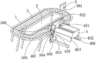
The invention discloses a sorting platform of an annular conveying system, which relates to the field of conveying and sorting equipment and comprises an annular frame, wherein a conveyor body is arranged on the inner side of the annular frame, a rotating roller is arranged at the top of the annular frame, and a blanking mechanism is arranged on the outer side of the annular frame. According to the invention, through arranging the blanking mechanism, when the device is used, the packages can be firstly dumped into the discharging hopper, the rotating roller can drive the reciprocating screw rod to rotate through the synchronizing wheel and the synchronizing belt when rotating, the L-shaped push rod can move along the reciprocating screw rod when the reciprocating screw rod rotates, so that one end of the discharging hopper, which is far away from the limiting rod, can be tilted, the packages in the discharging hopper can slide to the top of the rotating roller under the action of gravity, and then the discharging hopper can intermittently dump the packages through the back and forth movement of the L-shaped push rod along the reciprocating screw rod, so that the packages are prevented from falling on the rotating roller all at one time to influence the sorting of workers.
Description
Technical Field
The invention relates to the field of conveying and sorting equipment, in particular to a sorting platform of an annular conveying system.
Background
In the whole logistics distribution process, sorting is an important link, sorting is an operation of stacking articles in different categories according to the sequence of types and in and out of a warehouse, sorting is a preparatory work for perfecting and supporting delivery, and is an inevitable extension of competition and improvement of self economic benefit of different distribution enterprises in delivery, when a large number of goods are sorted, an annular conveying device is required to be used so as to improve sorting efficiency, most of the conveying devices for logistics sorting at present adopt linear conveying belts which are suitable for point-to-point goods conveying work, but are not completely suitable for goods sorting work, for example, under the condition that the goods are more, because the conveying belts can only drive the goods to move in one direction, each goods only pass through the front of sorting personnel once, and then the condition that the workers cannot timely collect and screen the goods on the conveying belts can easily occur, the annular conveying belt conveys articles in an annular mode through rotation of a plurality of rotating rollers, and therefore sorting of goods is facilitated.
General endless conveyor can carry out the annular to article and carry, but when falling the article that will need the letter sorting on endless conveyor, article can take place to pile up, when the article that the staff is piled up were sorted this moment, not only waste time and energy, also can increase the letter sorting cycle simultaneously, thereby influence letter sorting efficiency, because article on the endless conveyor are the annular and carry article, the part article that need the letter sorting just can move to unloading department again under endless conveyor's effect this moment, if fall external article this moment and can lead to taking place to pile up between the article on the endless conveyor, the extrusion, can cause inconvenience to the letter sorting of article.
Disclosure of Invention
The invention aims to: in order to solve the problem that the articles are inconvenient to be discontinuously loaded and cannot be moved, an annular conveying system sorting platform is provided.
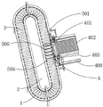
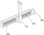
In order to achieve the purpose, the invention provides the following technical scheme: a sorting platform of an annular conveying system comprises an annular frame, wherein a conveyor body is arranged on the inner side of the annular frame, a rotating roller is arranged at the top of the annular frame, and a discharging mechanism is arranged on the outer side of the annular frame; the blanking mechanism comprises a limiting rod, a discharging hopper, a trapezoidal block, a reciprocating screw rod, an L-shaped push rod, a synchronous wheel, a synchronous belt and a connecting block, the limiting rod is arranged on the outer side of the annular frame, the discharging hopper is fixed on one side of the limiting rod, the trapezoidal block is arranged at two ends of the discharging hopper, the synchronous wheel is connected to one end of the rotary roller and is positioned on the outer side of the annular frame, the synchronous belt is arranged on the outer side of the synchronous wheel, the L-shaped push rod is arranged at the bottom of the trapezoidal block, the connecting block is fixed on the outer side of the annular frame and is positioned at one end of the L-shaped push rod, and the reciprocating screw rod is arranged on the inner side of the connecting block and is positioned at one end of the L-shaped push rod; and a material pushing mechanism is arranged at one side of the top of the annular frame, which is positioned on the discharge hopper, and is used for preventing articles from being stacked.
Therefore, when the equipment is used, the package can be firstly poured into the discharging hopper, then the rotary roller is rotated through the conveyor body, the rotary roller can drive the reciprocating screw rod to rotate through the synchronizing wheel and the synchronizing belt when rotating, the L-shaped push rod can move along the reciprocating screw rod when the reciprocating screw rod rotates, and at the moment, the L-shaped push rod can move along the inclined plane at the bottom of the trapezoidal block, so that one end of the discharging hopper far away from the limiting rod is tilted, the package in the discharging hopper can slide to the top of the rotating roller under the action of gravity, in the process, the package on one side of the discharging hopper can be lifted by the material pushing mechanism, the collision with the package being conveyed is prevented during the blanking, then the discharging hopper can be used for pouring the package discontinuously by the L-shaped push rod moving back and forth along the reciprocating screw rod, thereby preventing that the parcel once only all falls on the change roller and causes the influence to staff's letter sorting.
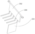
As a still further scheme of the invention: the pushing mechanism comprises a guide rod, a first baffle, a rack, a second baffle, a gear and a support frame, wherein the gear is fixed at two ends of a limiting rod, the guide rod is fixed at the top of the annular frame, the first baffle is sleeved on the outer side of the guide rod and located at one side of the discharging hopper, the rack is fixed at one side of the first baffle and located at one side of the gear, the second baffle is fixed at one side of the rack, the first baffle is far away from the second baffle, and the support frame is fixed at one side of the first baffle and located at one end of the second baffle.
Thus, when the limiting rod rotates and drives the discharging hopper to be far away from one end of the limiting rod to tilt, the gear rotates along with the rotation of the limiting rod, so that the rack moves upwards under the rotation of the gear, the first baffle plate can move upwards along the guide rod at the moment, the first baffle plate is positioned at the top of the rotating roller in the process, a parcel positioned on one side of the first baffle plate can move upwards under the action of the supporting frame, the second baffle plate can shield the parcel positioned on one end at the moment and prevent the parcel from moving to one side of the first baffle plate, so that the parcel in the discharging hopper can slide to the upper part of the rotating roller under the action of gravity, the parcel falling to the lower part of the supporting frame can be conveyed to the front of a worker to sort under the action of the rotating roller, and similarly, when the discharging hopper recovers, the supporting frame can move downwards under the action of the first baffle plate, so that the parcel on the supporting frame is contacted with the rotating roller, make the second baffle simultaneously lose the sheltering from to follow-up parcel to this makes changes the roller and carries the parcel under the effect of conveyer body, thereby prevents that the parcel from taking place to pile up, provides convenience for the staff to the letter sorting of parcel.
As a still further scheme of the invention: one end of the rack is meshed with the clamping teeth on the outer side of the gear, and through holes matched with the guide rods are formed in the two ends of the first baffle.
Therefore, the gear rotates along with the limiting rod through the structure to drive the rack to move, and the first baffle moves along the guide rod.
As a still further scheme of the invention: one end of the reciprocating screw rod is also provided with a synchronizing wheel, and the reciprocating screw rod is connected with the rotating roller through the synchronizing wheel and the synchronizing belt in a rotating mode.
So, when making the roller rotate under the effect of conveyer body through setting up this structure, drive reciprocal lead screw through synchronizing wheel, hold-in range and rotate.
As a still further scheme of the invention: one end of the L-shaped push rod is provided with a limiting ball matched with the outer side of the reciprocating screw rod, and one end of the connecting block is provided with a sliding groove matched with one end of the L-shaped push rod.
Thus, when the reciprocating screw rod rotates by the structure, the L-shaped push rod moves along the reciprocating screw rod.
As a still further scheme of the invention: and a rotating rod is arranged on the inner side of the discharging hopper.
So, reduce the frictional force between parcel and the blowing fill through setting up this structure for the parcel falls to changeing on the roller along the blowing fill when the blowing fill takes place the slope.
As a still further scheme of the invention: the bottom of the trapezoid block is provided with a sliding groove matched with the top of the L-shaped push rod, and the top of the L-shaped push rod is of a T-shaped structure.
So, move along the inclined plane of trapezoidal piece when making L shape push rod move through setting up this structure to the one end perk that the gag lever post was kept away from to messenger's blowing fill.
As a still further scheme of the invention: the number of the connecting blocks is two, and the two connecting blocks are symmetrically arranged along the transverse central axis of the annular frame.
Therefore, the stability of the swinging of the discharging hopper is improved by arranging the structure.
As a still further scheme of the invention: the support frame distribute in between the commentaries on classics roller, the top of support frame is less than with the height on ground of commentaries on classics roller to the height on ground.
So, prevent through setting up this structure that the support frame from causing the influence to the rotation of changeing the roller to prevent that the support frame from causing the hindrance to the removal of parcel.
Compared with the prior art, the invention has the beneficial effects that:
1. by arranging the blanking mechanism, when the equipment is used, the packages can be firstly dumped in the discharging hopper, the rotating roller can drive the reciprocating screw rod to rotate through the synchronizing wheel and the synchronizing belt when rotating, the L-shaped push rod can move along the reciprocating screw rod when the reciprocating screw rod rotates, so that one end of the discharging hopper, which is far away from the limiting rod, can tilt, the packages in the discharging hopper can slide to the top of the rotating roller under the action of gravity, and then the discharging hopper can intermittently dump the packages through the back-and-forth movement of the L-shaped push rod along the reciprocating screw rod, so that the packages are prevented from completely falling on the rotating roller at one time to influence the sorting of workers;
2. through setting up pushing equipment, when the gag lever post rotates and drives the blowing fill and keep away from the gag lever post one end perk, the rack upwards moves under the rotation of gear, this moment alright make first baffle upwards move along the guide bar, be located at this in-process and change the roller top, and the parcel that is located first baffle one side just can upwards move under the effect of support frame, the second baffle just can shelter from the parcel that is located one end this moment, the parcel that falls to the support frame below this moment just can carry under the effect of commentaries on classics roller and sort before staff, need not to fall the parcel again after observing the position of parcel on the commentaries on classics roller at this in-process, can make it along with the swing of blowing fill and operate, thereby the running cost of equipment has been reduced, also provide convenience for the staff to the letter sorting of parcel simultaneously.
Drawings
FIG. 1 is a schematic view of the structure of the present invention;
FIG. 2 is a top view of the present invention;
FIG. 3 is an enlarged view taken at A of FIG. 2 in accordance with the present invention;
FIG. 4 is a schematic view of the connection between the L-shaped push rod and the trapezoidal block of the present invention;
FIG. 5 is a schematic view of the connection of a first baffle plate and a second baffle plate of the present invention;
FIG. 6 is a schematic view of the connection between the L-shaped push rod and the connecting block according to the present invention;
fig. 7 is a schematic view of the structure of the discharge hopper of the present invention.
In the figure: 1. an annular frame; 2. a conveyor body; 3. rotating the roller; 4. a blanking mechanism; 401. a limiting rod; 402. a discharge hopper; 403. a trapezoidal block; 404. a reciprocating screw rod; 405. an L-shaped push rod; 406. a synchronizing wheel; 407. a synchronous belt; 408. connecting blocks; 5. a material pushing mechanism; 501. a guide bar; 502. a first baffle plate; 503. a rack; 504. a second baffle; 505. a gear; 506. a support frame.
Detailed Description
The technical solutions in the embodiments of the present invention will be clearly and completely described below with reference to the drawings in the embodiments of the present invention, and it is obvious that the described embodiments are only a part of the embodiments of the present invention, and not all of the embodiments. All other embodiments, which can be derived by a person skilled in the art from the embodiments given herein without making any creative effort, shall fall within the protection scope of the present invention.
In the description of the present invention, it should be noted that the terms "center", "upper", "lower", "left", "right", "vertical", "horizontal", "inner", "outer", etc., indicate orientations or positional relationships based on the orientations or positional relationships shown in the drawings, and are only for convenience of description and simplicity of description, but do not indicate or imply that the device or element being referred to must have a particular orientation, be constructed and operated in a particular orientation, and thus, should not be construed as limiting the present invention. Furthermore, the terms "first," "second," and "third" are used for descriptive purposes only and are not to be construed as indicating or implying relative importance. In the description of the present invention, it should be noted that, unless otherwise explicitly specified or limited, the terms "mounted," "connected," and "disposed" are to be construed broadly, e.g., as meaning either a fixed connection, a removable connection, or an integral connection; can be mechanically or electrically connected; they may be connected directly or indirectly through intervening media, or they may be interconnected between two elements. The specific meanings of the above terms in the present invention can be understood in specific cases to those skilled in the art. The following describes an embodiment of the present invention based on its overall structure.
Referring to fig. 1 to 7, in the embodiment of the present invention, an annular conveying system sorting platform includes an annular frame 1, a conveyor body 2 is disposed inside the annular frame 1, a rotating roller 3 is disposed at the top of the annular frame 1, and a blanking mechanism 4 is disposed outside the annular frame 1; the blanking mechanism 4 comprises a limiting rod 401, a discharge hopper 402, a trapezoidal block 403, a reciprocating screw rod 404, an L-shaped push rod 405, a synchronizing wheel 406, a synchronizing belt 407 and a connecting block 408, the limiting rod 401 is arranged on the outer side of the annular frame 1, the discharge hopper 402 is fixed on one side of the limiting rod 401, the trapezoidal block 403 is arranged at two ends of the discharge hopper 402, the synchronizing wheel 406 is connected to one end of the rotary roller 3 and is positioned on the outer side of the annular frame 1, the synchronizing belt 407 is arranged on the outer side of the synchronizing wheel 406, the L-shaped push rod 405 is arranged at the bottom of the trapezoidal block 403, the connecting block 408 is fixed on the outer side of the annular frame 1 and is positioned at one end of the L-shaped push rod 405, and the reciprocating screw rod 404 is arranged on the inner side of the connecting block 408 and is positioned at one end of the L-shaped push rod 405; the top of the ring frame 1 is provided with a material pushing mechanism 5 at one side of the material placing hopper 402 for preventing the articles from being piled up.
In this embodiment, when the device is used, the package can be firstly dumped into the discharging hopper 402, then the rotating roller 3 is rotated through the conveyor body 2, when the rotating roller 3 is rotated, the reciprocating screw rod 404 can be driven to rotate through the synchronizing wheel 406 and the synchronizing belt 407, when the reciprocating screw rod 404 is rotated, the L-shaped push rod 405 can move along the reciprocating screw rod 404, at this time, the L-shaped push rod 405 can move along the inclined plane at the bottom of the trapezoidal block 403, so that one end of the discharging hopper 402, which is far away from the limiting rod 401, is tilted, at this time, the package in the discharging hopper 402 can slide down to the top of the rotating roller 3 under the action of gravity, in the process, the package at one side of the discharging hopper 402 can be lifted through the material pushing mechanism 5, the collision with the package being conveyed during the discharging is prevented, and then the package can be intermittently dumped by the discharging hopper 402 through the back and forth movement of the L-shaped push rod 405 along the reciprocating screw rod 404, thereby preventing the packages from falling on the roller 3 all at once and causing influence on the sorting of the workers.
Please refer to fig. 1, 2, 3, 5, and 7, the pushing mechanism 5 includes a guiding rod 501, a first blocking plate 502, a rack 503, a second blocking plate 504, a gear 505, and a supporting frame 506, the gear 505 is fixed at two ends of the limiting rod 401, the guiding rod 501 is fixed at the top of the ring frame 1, the first blocking plate 502 is sleeved outside the guiding rod 501 and located at one side of the material placing hopper 402, the rack 503 is fixed at one side of the first blocking plate 502 and located at one side of the gear 505, the second blocking plate 504 is fixed at one side of the first blocking plate 502 far away from the rack 503, and the supporting frame 506 is fixed at one side of the first blocking plate 502 and located at one end of the second blocking plate 504.
In this embodiment, when the limiting rod 401 rotates and drives the end of the discharging hopper 402 far from the limiting rod 401 to tilt, the gear 505 rotates along with the rotation of the limiting rod 401, so that the rack 503 moves upward under the rotation of the gear 505, at this time, the first baffle 502 moves upward along the guide rod 501, the parcel on one side of the first baffle 502 moves upward under the action of the supporting frame 506, at this time, the second baffle 504 shields the parcel on one end to prevent it from moving to one side of the first baffle 502, so that the parcel in the discharging hopper 402 slides down to the upper side of the rotating roller 3 under the action of gravity, the parcel falling to the lower side of the supporting frame 506 is conveyed to the front of the operator under the action of the rotating roller 3 for sorting, and similarly, when the discharging hopper 402 recovers, the supporting frame 506 moves downward under the action of the first baffle 502, make parcel on the support frame 506 and changeing roller 3 contact with this, make second baffle 504 lose the sheltering from to follow-up parcel simultaneously to this makes changeing roller 3 and carries the parcel under conveyer body 2's effect, thereby prevents that the parcel from taking place to pile up, provides convenience for the sorting of staff to the parcel.
Please refer to fig. 1 and 3, one end of the rack 503 is engaged with the latch outside the gear 505, and both ends of the first blocking plate 502 are provided with through holes engaged with the guiding rods 501.
In the present embodiment, the gear 505 is rotated along with the stopper rod 401 to move the rack 503, thereby moving the first shutter 502 along the guide rod 501.
Please refer to fig. 3 and 6, one end of the reciprocating screw rod 404 is also provided with a synchronous wheel 406, and the reciprocating screw rod 404 is rotatably connected with the rotating roller 3 through the synchronous wheel 406 and the synchronous belt 407.
In the present embodiment, when the roller 3 is rotated by the conveyor body 2, the synchronous wheel 406 and the synchronous belt 407 drive the reciprocating screw rod 404 to rotate.
Please refer to fig. 6, one end of the L-shaped push rod 405 is provided with a limit ball matched with the outer side of the reciprocating screw rod 404, and one end of the connecting block 408 is provided with a chute matched with one end of the L-shaped push rod 405.
In the present embodiment, when the reciprocating screw 404 is rotated by providing this structure, the L-shaped push rod 405 moves along the reciprocating screw 404.
Referring to fig. 7, the discharging hopper 402 is provided with a rotating rod inside.
In the present embodiment, the friction between the parcel and the hopper 402 is reduced by providing this structure, so that the parcel falls onto the rotating roller 3 along the hopper 402 when the hopper 402 is tilted.
Please refer to fig. 4 and 6, the bottom of the trapezoid block 403 is provided with a sliding slot matching with the top of the L-shaped push rod 405, and the top of the L-shaped push rod 405 is a T-shaped structure.
In the present embodiment, the L-shaped push rod 405 moves along the inclined surface of the trapezoidal block 403 when moving due to the structure, so that the end of the discharging hopper 402 away from the stopper rod 401 tilts.
Please refer to fig. 1, the number of the connecting blocks 408 is two, and the two connecting blocks 408 are symmetrically arranged along the transverse central axis of the ring frame 1.
In the present embodiment, the stability of the swing of the hopper 402 is increased by providing this structure.
Please refer to fig. 1 and 5, the supporting frame 506 is distributed between the rollers 3, and the height between the top of the supporting frame 506 and the ground is less than the height between the rollers 3 and the ground.
In the present embodiment, the support frame 506 is prevented from affecting the rotation of the rotating roller 3 by providing this structure, thereby preventing the support frame 506 from hindering the movement of the package.
The working principle of the invention is as follows: when the device is used, a package can be firstly poured into the discharging hopper 402, then the rotating roller 3 is rotated through the conveyor body 2, when the rotating roller 3 rotates, the reciprocating screw rod 404 can be driven by the synchronizing wheel 406 and the synchronizing belt 407 to rotate, when the reciprocating screw rod 404 rotates, the L-shaped push rod 405 can move along the reciprocating screw rod 404, at the moment, the L-shaped push rod 405 can move along the inclined plane at the bottom of the trapezoidal block 403, so that one end, away from the limiting rod 401, of the discharging hopper 402 can be tilted, at the moment, the package in the discharging hopper 402 can slide to the top of the rotating roller 3 under the action of gravity, when the limiting rod 401 rotates and drives one end, away from the limiting rod 401, of the discharging hopper 402 to tilt, the gear 505 can rotate along with the rotation of the limiting rod 401, so that the rack 503 can move upwards under the rotation of the gear 505, at the moment, the first baffle 502 can move upwards along the guide rod 501, in the process, the parcels positioned at the top of the rotating roller 3 and positioned at one side of the first baffle plate 502 move upwards under the action of the support frame 506, at the moment, the parcels positioned at one end can be shielded by the second baffle plate 504 to be prevented from moving to one side of the first baffle plate 502, so that the parcels in the discharging hopper 402 can slide to the upper part of the rotating roller 3 under the action of gravity, the parcels falling to the lower part of the support frame 506 can be conveyed to the front of workers under the action of the rotating roller 3 to be sorted, when the discharging hopper 402 recovers, the support frame 506 can move downwards under the action of the first baffle plate 502 to enable the parcels on the support frame 506 to be in contact with the rotating roller 3, and simultaneously enable the second baffle plate 504 to lose shielding of the subsequent parcels, so that the rotating roller 3 conveys the parcels under the action of the conveyor body 2, thereby preventing the parcels from being piled up and providing convenience for the workers to sort the parcels, the collision with the parcel that is carrying when preventing to unload, later make the blowing fill 402 carry out the discontinuous and empty to the parcel through L shape push rod 405 along reciprocating screw rod 404 round trip movement to prevent that the parcel is once only all fallen on roller 3 and cause the influence to staff's letter sorting.
The above description is only for the preferred embodiment of the present invention, but the scope of the present invention is not limited thereto, and any person skilled in the art should be considered to be within the technical scope of the present invention, and the technical solutions and the inventive concepts thereof according to the present invention are equivalent to or changed within the technical scope of the present invention.
Claims (8)
1. The sorting platform of the annular conveying system comprises an annular frame (1), wherein a conveyor body (2) is arranged on the inner side of the annular frame (1), a rotating roller (3) is arranged at the top of the annular frame (1), and the sorting platform is characterized in that a blanking mechanism (4) is arranged on the outer side of the annular frame (1);
the blanking mechanism (4) comprises a limiting rod (401), a discharging hopper (402), a trapezoidal block (403), a reciprocating screw rod (404), an L-shaped push rod (405), a synchronous wheel (406), a synchronous belt (407) and a connecting block (408), the limiting rod (401) is arranged on the outer side of the annular frame (1), the discharging hopper (402) is fixed on one side of the limiting rod (401), the trapezoidal block (403) is arranged at two ends of the discharging hopper (402), the synchronous wheel (406) is connected to one end of the rotary roller (3) and is positioned on the outer side of the annular frame (1), the synchronous belt (407) is arranged on the outer side of the synchronous wheel (406), the L-shaped push rod (405) is arranged at the bottom of the trapezoidal block (403), the connecting block (408) is fixed on the outer side of the annular frame (1) and is positioned at one end of the L-shaped push rod (405), the reciprocating screw rod (404) is arranged on the inner side of the connecting block (408) and is positioned at one end of the L-shaped push rod (405);
a material pushing mechanism (5) is arranged on one side, located on the material discharging hopper (402), of the top of the annular frame (1) and used for preventing articles from being stacked;
pushing equipment (5) is including guide bar (501), first baffle (502), rack (503), second baffle (504), gear (505), support frame (506), gear (505) are fixed in the both ends of gag lever post (401), guide bar (501) are fixed in the top of ring frame (1), first baffle (502) cup joint in the outside of guide bar (501), and are located one side of blowing fill (402), rack (503) are fixed in one side of first baffle (502), and are located one side of gear (505), second baffle (504) are fixed in one side of rack (503) is kept away from in first baffle (502), support frame (506) are fixed in one side of first baffle (502), and are located the one end of second baffle (504).
2. The sorting platform of the circular conveying system according to claim 1, wherein one end of the rack (503) is engaged with a latch outside the gear (505), and both ends of the first baffle (502) are provided with through holes engaged with the guide rods (501).
3. The sorting platform of the circular conveying system according to claim 1, wherein one end of the reciprocating screw rod (404) is also provided with a synchronous wheel (406), and the reciprocating screw rod (404) is rotationally connected with the rotating roller (3) through the synchronous wheel (406) and the synchronous belt (407).
4. The sorting platform of the annular conveying system according to claim 1, wherein one end of the L-shaped push rod (405) is provided with a limiting ball matched with the outer side of the reciprocating screw rod (404), and one end of the connecting block (408) is provided with a sliding groove matched with one end of the L-shaped push rod (405).
5. An endless conveyor system sorting platform according to claim 1, characterised in that inside the emptying hopper (402) is arranged a turning bar.
6. The sorting platform of the circular conveying system according to claim 1, wherein the bottom of the trapezoidal block (403) is provided with a sliding groove matched with the top of the L-shaped push rod (405), and the top of the L-shaped push rod (405) is of a T-shaped structure.
7. Sorting platform according to claim 1, characterised in that there are two connection blocks (408) and that the two connection blocks (408) are symmetrically arranged along the transversal central axis of the annular frame (1).
8. The sorting platform of claim 1, wherein the supporting frames (506) are distributed between the rollers (3), and the height between the top of the supporting frames (506) and the ground is less than the height between the rollers (3) and the ground.
Priority Applications (1)
| Application Number | Priority Date | Filing Date | Title |
|---|---|---|---|
| CN202210701526.7A CN114772149B (en) | 2022-06-21 | 2022-06-21 | Annular conveying system letter sorting platform |
Applications Claiming Priority (1)
| Application Number | Priority Date | Filing Date | Title |
|---|---|---|---|
| CN202210701526.7A CN114772149B (en) | 2022-06-21 | 2022-06-21 | Annular conveying system letter sorting platform |
Publications (2)
| Publication Number | Publication Date |
|---|---|
| CN114772149A CN114772149A (en) | 2022-07-22 |
| CN114772149B true CN114772149B (en) | 2022-09-20 |
Family
ID=82420379
Family Applications (1)
| Application Number | Title | Priority Date | Filing Date |
|---|---|---|---|
| CN202210701526.7A Active CN114772149B (en) | 2022-06-21 | 2022-06-21 | Annular conveying system letter sorting platform |
Country Status (1)
| Country | Link |
|---|---|
| CN (1) | CN114772149B (en) |
Families Citing this family (1)
| Publication number | Priority date | Publication date | Assignee | Title |
|---|---|---|---|---|
| CN116142580B (en) * | 2023-02-17 | 2024-04-05 | 沂水祥腾化工有限公司 | Conveying device for textile fabric production with conveying direction changed |
Citations (8)
| Publication number | Priority date | Publication date | Assignee | Title |
|---|---|---|---|---|
| ES439104A1 (en) * | 1974-07-04 | 1977-03-01 | Sphere Invest | Sorting apparatus |
| CN204504988U (en) * | 2014-12-30 | 2015-07-29 | 重庆厚丰机械有限责任公司 | The material rotaring machine of steel ball lapping machine |
| CN210456201U (en) * | 2019-08-14 | 2020-05-05 | 深圳市三维机电设备有限公司 | Rotary circulating conveying device with clamp positioning function |
| CN111747081A (en) * | 2020-07-06 | 2020-10-09 | 汕头市陀斯包装机械有限公司 | Automatic packaging machine |
| CN112407472A (en) * | 2020-11-12 | 2021-02-26 | 湖南嘉丰食品有限公司 | Yolk weight packing device |
| CN213566814U (en) * | 2020-09-29 | 2021-06-29 | 苏州医疗用品厂有限公司 | Pipe needle receiving device |
| CN113387196A (en) * | 2021-06-30 | 2021-09-14 | 湖北中烟工业有限责任公司 | Filter stick arranging and conveying device |
| CN214293302U (en) * | 2020-12-25 | 2021-09-28 | 福建正大食品有限公司 | Material preparation system for chicken companion wing processing |
-
2022
- 2022-06-21 CN CN202210701526.7A patent/CN114772149B/en active Active
Patent Citations (8)
| Publication number | Priority date | Publication date | Assignee | Title |
|---|---|---|---|---|
| ES439104A1 (en) * | 1974-07-04 | 1977-03-01 | Sphere Invest | Sorting apparatus |
| CN204504988U (en) * | 2014-12-30 | 2015-07-29 | 重庆厚丰机械有限责任公司 | The material rotaring machine of steel ball lapping machine |
| CN210456201U (en) * | 2019-08-14 | 2020-05-05 | 深圳市三维机电设备有限公司 | Rotary circulating conveying device with clamp positioning function |
| CN111747081A (en) * | 2020-07-06 | 2020-10-09 | 汕头市陀斯包装机械有限公司 | Automatic packaging machine |
| CN213566814U (en) * | 2020-09-29 | 2021-06-29 | 苏州医疗用品厂有限公司 | Pipe needle receiving device |
| CN112407472A (en) * | 2020-11-12 | 2021-02-26 | 湖南嘉丰食品有限公司 | Yolk weight packing device |
| CN214293302U (en) * | 2020-12-25 | 2021-09-28 | 福建正大食品有限公司 | Material preparation system for chicken companion wing processing |
| CN113387196A (en) * | 2021-06-30 | 2021-09-14 | 湖北中烟工业有限责任公司 | Filter stick arranging and conveying device |
Also Published As
| Publication number | Publication date |
|---|---|
| CN114772149A (en) | 2022-07-22 |
Similar Documents
| Publication | Publication Date | Title |
|---|---|---|
| CN1069875C (en) | Automated facility for unscrambling of light, hollow, elongated articles and for lined up delivery of said articles | |
| CN114772149B (en) | Annular conveying system letter sorting platform | |
| US6398008B1 (en) | Aligning and conveying method of packaged article and apparatus thereof | |
| US5735661A (en) | Transporter for storing and carrying multiple articles, such as coin collection boxes | |
| JPH07110654B2 (en) | Container feeder | |
| CN104670554B (en) | Unloading device of knife, fork and scoop packing machine | |
| CN113182190A (en) | Transportation classification taking-out device | |
| CN111871755B (en) | Material sorting device based on computer control | |
| CN210011970U (en) | Automatic detection packaging device | |
| CN114516432B (en) | Solid filling equipment, filling line and filling method | |
| CN109926354B (en) | Conveying belt for logistics sorting | |
| CN216606169U (en) | Chute type weighing and sorting device for materials | |
| CN110481870A (en) | A kind of boxing apparatus for lithium battery packaging | |
| CN112061441B (en) | Cheese counterweight device and counterweight method thereof | |
| CN210701268U (en) | Big and small piece fusion sorting device | |
| CN219546039U (en) | Material box bearing device of backstop sorting machine and cargo sorting machine | |
| CN213409446U (en) | Movable storage vehicle and secondary sorting system with same | |
| CN218397897U (en) | Automatic assembling machine for bolt gasket | |
| CN110668142A (en) | Sorting device | |
| CN220153710U (en) | Material weighing device | |
| CN217141318U (en) | Fruit selecting device | |
| CN215362125U (en) | Logistics object processing device | |
| CN219383738U (en) | Anti-drop's storage conveyer | |
| CN213762886U (en) | Article sorting system | |
| CN218554796U (en) | Telescopic machine for sorting packages |
Legal Events
| Date | Code | Title | Description |
|---|---|---|---|
| PB01 | Publication | ||
| PB01 | Publication | ||
| SE01 | Entry into force of request for substantive examination | ||
| SE01 | Entry into force of request for substantive examination | ||
| GR01 | Patent grant | ||
| GR01 | Patent grant |