CN114604627A - Graphite boat piece stuck point replacing device - Google Patents
Graphite boat piece stuck point replacing device Download PDFInfo
- Publication number
- CN114604627A CN114604627A CN202210155133.0A CN202210155133A CN114604627A CN 114604627 A CN114604627 A CN 114604627A CN 202210155133 A CN202210155133 A CN 202210155133A CN 114604627 A CN114604627 A CN 114604627A
- Authority
- CN
- China
- Prior art keywords
- graphite boat
- stuck point
- positioning tool
- boat piece
- axis
- Prior art date
- Legal status (The legal status is an assumption and is not a legal conclusion. Google has not performed a legal analysis and makes no representation as to the accuracy of the status listed.)
- Granted
Links
- OKTJSMMVPCPJKN-UHFFFAOYSA-N Carbon Chemical compound [C] OKTJSMMVPCPJKN-UHFFFAOYSA-N 0.000 title claims abstract description 74
- 229910002804 graphite Inorganic materials 0.000 title claims abstract description 74
- 239000010439 graphite Substances 0.000 title claims abstract description 74
- 230000007246 mechanism Effects 0.000 claims abstract description 120
- 238000001179 sorption measurement Methods 0.000 claims abstract description 7
- 238000003825 pressing Methods 0.000 claims description 17
- 238000001514 detection method Methods 0.000 claims description 8
- 239000000463 material Substances 0.000 claims description 8
- 230000000007 visual effect Effects 0.000 claims description 8
- 238000001125 extrusion Methods 0.000 claims description 4
- 238000010521 absorption reaction Methods 0.000 claims 2
- 238000007599 discharging Methods 0.000 abstract description 11
- 241000252254 Catostomidae Species 0.000 abstract 2
- 230000001360 synchronised effect Effects 0.000 description 11
- 238000010586 diagram Methods 0.000 description 4
- 230000008859 change Effects 0.000 description 3
- 238000011179 visual inspection Methods 0.000 description 3
- XUIMIQQOPSSXEZ-UHFFFAOYSA-N Silicon Chemical compound [Si] XUIMIQQOPSSXEZ-UHFFFAOYSA-N 0.000 description 2
- 230000009471 action Effects 0.000 description 2
- 229910052710 silicon Inorganic materials 0.000 description 2
- 239000010703 silicon Substances 0.000 description 2
- 239000000758 substrate Substances 0.000 description 2
- 230000007547 defect Effects 0.000 description 1
- 238000004519 manufacturing process Methods 0.000 description 1
- 238000000034 method Methods 0.000 description 1
- 230000008569 process Effects 0.000 description 1
Images


Classifications
-
- B—PERFORMING OPERATIONS; TRANSPORTING
- B65—CONVEYING; PACKING; STORING; HANDLING THIN OR FILAMENTARY MATERIAL
- B65G—TRANSPORT OR STORAGE DEVICES, e.g. CONVEYORS FOR LOADING OR TIPPING, SHOP CONVEYOR SYSTEMS OR PNEUMATIC TUBE CONVEYORS
- B65G47/00—Article or material-handling devices associated with conveyors; Methods employing such devices
- B65G47/74—Feeding, transfer, or discharging devices of particular kinds or types
- B65G47/90—Devices for picking-up and depositing articles or materials
- B65G47/91—Devices for picking-up and depositing articles or materials incorporating pneumatic, e.g. suction, grippers
- B65G47/912—Devices for picking-up and depositing articles or materials incorporating pneumatic, e.g. suction, grippers provided with drive systems with rectilinear movements only
-
- B—PERFORMING OPERATIONS; TRANSPORTING
- B25—HAND TOOLS; PORTABLE POWER-DRIVEN TOOLS; MANIPULATORS
- B25B—TOOLS OR BENCH DEVICES NOT OTHERWISE PROVIDED FOR, FOR FASTENING, CONNECTING, DISENGAGING OR HOLDING
- B25B11/00—Work holders not covered by any preceding group in the subclass, e.g. magnetic work holders, vacuum work holders
- B25B11/02—Assembly jigs
-
- B—PERFORMING OPERATIONS; TRANSPORTING
- B25—HAND TOOLS; PORTABLE POWER-DRIVEN TOOLS; MANIPULATORS
- B25B—TOOLS OR BENCH DEVICES NOT OTHERWISE PROVIDED FOR, FOR FASTENING, CONNECTING, DISENGAGING OR HOLDING
- B25B27/00—Hand tools, specially adapted for fitting together or separating parts or objects whether or not involving some deformation, not otherwise provided for
- B25B27/02—Hand tools, specially adapted for fitting together or separating parts or objects whether or not involving some deformation, not otherwise provided for for connecting objects by press fit or detaching same
-
- Y—GENERAL TAGGING OF NEW TECHNOLOGICAL DEVELOPMENTS; GENERAL TAGGING OF CROSS-SECTIONAL TECHNOLOGIES SPANNING OVER SEVERAL SECTIONS OF THE IPC; TECHNICAL SUBJECTS COVERED BY FORMER USPC CROSS-REFERENCE ART COLLECTIONS [XRACs] AND DIGESTS
- Y02—TECHNOLOGIES OR APPLICATIONS FOR MITIGATION OR ADAPTATION AGAINST CLIMATE CHANGE
- Y02P—CLIMATE CHANGE MITIGATION TECHNOLOGIES IN THE PRODUCTION OR PROCESSING OF GOODS
- Y02P70/00—Climate change mitigation technologies in the production process for final industrial or consumer products
- Y02P70/50—Manufacturing or production processes characterised by the final manufactured product
Abstract
The invention discloses a graphite boat piece clamping point replacing device which comprises an adsorption feeding and discharging mechanism, a positioning tool and a disassembling and assembling mechanism, wherein the adsorption feeding and discharging mechanism comprises an XZ shaft moving mechanism and a plurality of suckers, the positioning tool is used for bearing a graphite boat piece, the XZ shaft moving mechanism drives the suckers to carry out graphite boat piece feeding and discharging on the positioning tool, the disassembling and assembling mechanism is used for disassembling and replacing clamping points of the graphite boat piece on the positioning tool, and old clamping points on the graphite boat piece are replaced by new clamping points in an extruding mode when the clamping points are disassembled and replaced. According to the invention, the old clamping point is directly extruded and replaced by the new clamping point at the dismounting and replacing clamping point through the dismounting mechanism, so that the operation steps are reduced, and the clamping point replacing efficiency is improved.
Description
Technical Field
The invention relates to a graphite boat piece processing device, in particular to a graphite boat piece clamping point replacing device.
Background
The graphite boat piece is used for bearing and fixing a silicon wafer, a plurality of through holes are formed in the surface of the graphite boat piece, and clamping points are embedded into the through holes and used for fixing the silicon wafer. At present, the stuck point of embedding through-hole is a continuous consumptive material, produces about 45 days and need change, and along with the increase of production productivity, it is very big to lead to the demand of graphite boat moreover, and needs the manual work to dismantle the stuck point in the past for the interior cost of labor of mill sharply increases. The personnel carry out the change of stuck point, when impressing the stuck point, the problem that can produce the crushing graphite boat piece frequently, and the graphite boat piece is forged and is expensive moreover, has caused the damage if there is a stuck point, and whole graphite boat piece can report useless.
In the prior art, an assembling and disassembling device for a graphite boat clamping point is developed, and for example, a device disclosed in chinese patent publication No. CN113118725A includes a pressing mechanism, a disassembling and assembling structure, and a visual detection and positioning mechanism, which move on an XY plane by a driving machine of an XY axis, and are detected and positioned by the visual detection and positioning mechanism, so as to improve the mounting accuracy. When the device is used for replacing the clamping point of the graphite boat piece, the original clamping point is required to be pressed out of the graphite boat piece by the dismounting mechanism, then the new clamping point is pressed into the graphite boat piece by the pressing mechanism, and the clamping point can be replaced by two steps of actions.
Disclosure of Invention
In view of the above-mentioned defects of the prior art, the present invention is directed to provide a graphite boat sheet stuck point replacing device, which further improves the efficiency of replacing the stuck point of the graphite boat.
The technical scheme of the invention is as follows: the utility model provides a graphite boat piece stuck point changing device, includes unloading mechanism, location frock and dismouting mechanism on adsorbing, unloading mechanism includes XZ axle moving mechanism and a plurality of sucking disc on adsorbing, the location frock is used for bearing graphite boat piece, the drive of XZ axle moving mechanism the sucking disc is right the location frock carries out graphite boat piece and goes up the unloading, dismouting mechanism is used for right graphite boat piece on the location frock is torn open and is traded the stuck point, extrude the replacement by new stuck point when tearing open and trade the stuck point old stuck point on the graphite boat piece.
Further, dismouting mechanism includes XY axle moving mechanism and tears open and trade the terminal, tear open and trade the terminal and include the base, be fixed with visual detection mechanism, stuck point feed mechanism, stuck point pushing down mechanism and collet on the base, visual detection mechanism is used for detecting the stuck point position of graphite boat piece, stuck point feed mechanism includes feed board and feed chute, be equipped with the feed tank on the feed board, the feed chute with the feed tank meets, lie in on the feed board feed tank end is equipped with Z axial through-hole, be equipped with in the feed tank and be used for to the through-hole promotes the flexible ejector pin of stuck point, stuck point pushing down mechanism include push down actuating mechanism and by push down actuating mechanism driven pushing down the pole, the pushing down the pole is located directly over the through-hole, the collet is including being located the Z axle lift piece of feed board below, the Z-axis lifting block is correspondingly provided with a discharging through hole, when a clamping point is removed, the graphite boat piece on the positioning tool is positioned between the feeding plate and the Z-axis lifting block, and the XY-axis moving mechanism drives the base according to the clamping point position and enables the lower pressing rod to be aligned with the clamping point of the graphite boat piece on the positioning tool.
Further, the lower surface of feed plate is equipped with the boss, the through-hole runs through the boss. When the Z-axis lifting block is lifted, the Z-axis lifting block and the boss form clamping for the graphite boat piece, so that the clamping area is reduced, and the risk of damage to the graphite boat piece is reduced.
Further, the positioning tool comprises a cross beam and a plurality of bearing blocks, wherein the bearing blocks are arranged along the cross beam at intervals and enable the clamping points of the graphite boat pieces to be located in the intervals between the bearing blocks.
Furthermore, the head end of the bearing block is provided with a limit boss, and the beam is connected with a positioning push rod which extends towards the limit boss.
Furthermore, a slope slide way is arranged below the positioning tool and used for collecting the replaced old clamping points.
Further, for raising the efficiency, the location frock is equipped with two and is first location frock and second location frock respectively, first location frock with the position of second location frock exchanges in turn, first location frock with second location frock is located the position and is equipped with material level and dismouting position respectively, adsorption unloading mechanism carries out graphite boat piece unloading for the location frock that is in the material level of being equipped with, the card point is torn open and trade to the graphite boat piece on the location frock that is in the dismouting position to the dismouting mechanism.
Furthermore, the X-axis driving mechanism drives the first positioning tool and the Z-axis driving mechanism to move along the X axis, and the second positioning tool is driven by the Z-axis driving mechanism to move along the Z axis and move along the X axis along with the Z-axis driving mechanism.
Compared with the prior art, the invention has the advantages that:
the new clamping point extrudes and replaces the old clamping point, so that the operation steps are reduced, and the replacement efficiency can be improved; the dismounting and replacing mechanism provided with the bottom support supports the graphite boat piece when an old clamping point is pressed out and a new clamping point is pressed in, so that the damage risk is effectively reduced; adopt two location frock replacement operations, but the time of make full use of extrusion new stuck point carries out graphite boat piece and goes up unloading, saves time, has further improved efficiency.
Drawings
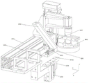
Fig. 1 is a schematic structural diagram of a graphite boat piece sticking point replacing device according to an embodiment of the present invention.
Fig. 2 is a schematic structural diagram of an adsorption loading and unloading mechanism according to an embodiment of the present invention.
Fig. 3 is a schematic structural diagram of a double-positioning tool alternating mechanism according to an embodiment of the present invention.
Fig. 4 is a schematic structural view of an X-axis driving mechanism of the double-positioning tool alternating mechanism.
Fig. 5 is a schematic structural diagram of a dismounting mechanism according to an embodiment of the present invention.
Fig. 6 is a schematic structural view of the dismounting terminal of the dismounting mechanism.
Fig. 7 is a schematic side view of the detachable terminal of the detaching mechanism (the visual inspection mechanism is not shown).
Fig. 8 is a schematic view of the dismounting terminal structure of the dismounting mechanism (the visual inspection mechanism is not shown).
Detailed Description
The present invention is further illustrated by the following examples, which are not to be construed as limiting the invention thereto.
In an embodiment, please refer to fig. 1, the embodiment relates to a graphite boat blade clamping point replacing device with a dual-positioning tool, which includes a frame 1, and an adsorbing feeding and discharging mechanism 2, a dual-positioning tool alternating mechanism 3 and a disassembling and assembling mechanism 4 are disposed on the frame 1. The adsorption feeding and discharging mechanism 2, the double-positioning tool alternating mechanism 3 and the dismounting mechanism 4 are arranged in the X axial direction. Two location frock mechanism 3 in turn includes two location frock, be first location frock 31 and second location frock 32 respectively, two location frock mechanism 3 in turn makes the position of first location frock 31 and second location frock 32 alternate in turn in the X axle direction, position between them is defined as being equipped with material level and dismouting position respectively, the location frock is in the material level of being equipped with the material loading of waiting to dismantle graphite boat piece, and the unloading of graphite boat piece after the stuck point change finishes, the location frock is in the extrusion replacement of dismantling new old stuck point.
The specific structure of each mechanism is described in detail below, please refer to fig. 2, the adsorbing and feeding and discharging mechanism 2 includes an XZ-axis moving mechanism 21 and a plurality of suction cups 22, the XZ-axis moving mechanism 21 includes a first X-axis linear module 2101 and a Z-axis linear module 2102 which are arranged on the top of the whole replacing device, the Z-axis linear module 2102 is driven by the first X-axis linear module 2101 to perform X-axis translation, the Z-axis linear module 2101 is connected with a Y-axis bracket 23, the length direction of the Y-axis bracket 23 is the length direction of the graphite boat, a vacuum generator and 20 (10 pairs) of suction cups 22 are arranged on the Y-axis bracket 23, the suction cups 22 are used for adsorbing the graphite boat, and a feeding stack (to-be-disassembled graphite boat) and a discharging stack (stacked graphite boat after the replacement of the clamping points) of the graphite boat a are formed on the frame 1.
As shown in fig. 3, the dual-positioning tool alternating mechanism 3 includes an X-axis driving mechanism 33 and a first Z-axis driving mechanism 34 in addition to the first positioning tool 31 and the second positioning tool 32. The X-axis driving mechanism 33 is provided with two ends located at the first positioning tool 31 and the second positioning tool 32, and each X-axis driving mechanism 33 is connected with one first Z-axis driving mechanism 34. The structure of first location frock 31 and second location frock 32 is the same, comprises crossbeam 301, a plurality of carrier block 302 and location push rod 303, and crossbeam 301 is Y axle direction and extends, and carrier block 302 sets up at the interval on crossbeam 301, by carrier block 302 carrier graphite boat piece, when graphite boat piece was placed on the location frock, can make the stuck point be in the interval between carrier block 302, left sufficient space for follow-up dismouting mechanism 4 carries out stuck point extrusion replacement. The head end of the bearing block 302 is provided with a limit boss 3021 protruding upwards, and the tail end of the beam 301 positioned on the bearing block 302 is connected with a positioning push rod 303 extending towards the limit boss 3021. After the graphite boat piece is carried to the positioning tool by the adsorption feeding and discharging mechanism 2, the positioning push rod pushes the front edge of the graphite boat piece forwards to abut against the limiting boss 3021 for positioning and fixing. As shown in fig. 4, the X-axis driving mechanism 33 includes a servo motor 3301, a primary synchronous pulley 3302, a secondary synchronous pulley 3303, and a synchronous belt 3304, a rotating shaft of the servo motor 3301 is disposed in a Z-axis direction and connected to the primary synchronous pulley 3302, the secondary synchronous pulley 3303 and the primary synchronous pulley 3302 are disposed at an interval in the X-axis direction, the synchronous belt 3304 is disposed in a ring around the primary synchronous pulley 3302 and the secondary synchronous pulley 3303, a first vertical plate 3305 and a second vertical plate 3306 are disposed on two sides of the ring around the synchronous belt 3304, a first X-axis sliding rail 3307 is disposed on the first vertical plate 3305, and a first sliding block 3308 matched with the first X-axis sliding rail 3307 is fixedly connected to a cross beam of the first positioning tool 31. Meanwhile, the synchronous belt 3304 close to one side of the first vertical plate 3305 is also fixedly connected with the beam of the first positioning tool 31. When the servo motor 3301 drives the primary timing pulley 3302 to rotate, the timing belt 3304 pulls the first positioning tool 31 to move along the first X-axis slide rail 3307. A second X-axis slide rail 3309 is disposed on the second vertical plate 3306, and a second slide block 3310 disposed on the second X-axis slide rail 3309 is fixedly connected to the first Z-axis driving mechanism 34. While the timing belt 3304 on the side adjacent to the second plate 3306 is also connected to the first Z-axis drive mechanism 34. First Z axle actuating mechanism 34 can adopt cylinder actuating mechanism, and the telescopic link of cylinder is the setting of Z axle direction to it is fixed with the crossbeam of second location frock 32, and it drives second location frock 32 and carries out Z axial lift. When the timing belt 3304 pulls the first positioning tool 31 to move along the first X-axis slide rail 3307 (assuming that the X-axis moves in a positive direction), at the same time, the timing belt 3304 pulls the first Z-axis driving mechanism 34 to move along the second X-axis slide rail 3309 (this is the X-axis moves in a negative direction). Since the first Z-axis driving mechanism 34 is directly connected to the second positioning mechanism 32, the first positioning tool 31 and the second positioning tool 32 are alternated in the X-axis direction. It should be noted that, before the alternating action is performed, the first Z-axis driving mechanism 34 should first drive the second positioning mechanism 32 to perform Z-axis lifting, and then perform Z-axis descending after the movement in the X-axis direction is completed, so as to achieve accurate replacement of the positions of the first positioning tool 31 and the second positioning tool 32.
As shown in fig. 5, the dismounting mechanism includes an XY axis moving mechanism 41 and a dismounting terminal 42, the XY axis moving mechanism 41 includes a second X axis linear module 4101 and a Y axis linear module 4102 disposed on the rack, a driving mechanism of the second X axis linear module 4101 is connected to the middle of the substrate of the Y axis linear module 4102, and two ends of the substrate of the Y axis linear module 4102 are connected to the X axis guide 4103 to ensure the smooth movement of the X axis. As shown in fig. 6 to 8, the detachable terminal 42 includes a base 4201, and the base 4201 is driven by a Y-axis linear module 4102. The base 4201 is fixed with a visual detection mechanism 4202, a clamping point feeding mechanism, a clamping point pressing mechanism and a bottom support, the visual detection mechanism 4202 is used for shooting and detecting the clamping point position of the graphite boat, the clamping point feeding mechanism comprises a feeding plate 4203 and a feeding chute 4204, a horizontal feeding groove 4203a is arranged on the feeding plate, and the feeding chute 4204 is connected with the feeding groove 4203 a. The width of the feed chute 4204 and the width of the feed chute 4203a are equal to the width of one click, and the click is arranged in the feed chute 4204 and then slid into the feed chute 4203a one by one. The feed plate 4203 is provided with a through hole 4203b in the Z-axis direction at the end of the feed groove 4203a, and the lower surface of the feed plate is provided with a boss 4203c through which the through hole 4203b penetrates the boss 4203 c. The inside of the feed chute 4203a is provided with a telescopic pusher 4205 for pushing the stuck point to the through hole, the telescopic pusher 4205 is controlled by the cylinder 4206 to be telescopic, the telescopic pusher 4205 retracts to the position where the feed chute 4024 and the feed chute 4203a meet when retracted, one stuck point in the feed chute 4204 falls into the feed chute 4203a, and then the telescopic pusher 4205 extends to push the stuck point into the through hole 4203b, the falling of the stuck point in the feed chute 4204 is blocked by the telescopic pusher 4205, and the stuck point in the feed chute 4205 falls one after the telescopic pusher 4205 retracts to the position where the feed chute 4205 and the feed chute 4203a meet again, so that the feeding of the stuck points one by one is performed in a circulating manner. When all the stuck points in the feed chute 4205 are used up, the XY-axis moving mechanism 41 is operated to align the feed chute 4204 with the external feed mechanism 5 to receive a new batch of stuck points.
The stuck point pressing mechanism comprises a pressing driving mechanism 4206 and a pressing rod 4207 driven by the pressing driving mechanism 4210, the pressing driving mechanism 4210 is a cylinder in the Z-axis direction, the cylinder rod is fixedly connected with the pressing rod 4207, and the pressing rod 4207 is located right above the through hole 4203 b. The shoe includes a Z-axis lift block 4208 positioned below the feed plate 4203, the Z-axis lift block 4208 being raised and lowered by another Z-axis cylinder 4209. A discharging through hole 4208a is formed on the Z-axis lifting block 4208 corresponding to the through hole 4203b, and the aperture of the discharging through hole 4208a is larger than the diameter of the clamping point so that the old clamping point can directly fall down. When the clamping points are removed and replaced, the graphite boat piece on the positioning tool is positioned between the feeding plate 4203 and the Z-axis lifting block 4208, the Z-axis lifting block 4208 is lifted, the Z-axis lifting block 4208 and the boss 4203c clamp the graphite boat piece, clamping area is reduced, and damage risk of the graphite boat piece is reduced. The specific process of the dismounting and replacing operation is that, firstly, the XY-axis moving mechanism 41 is operated to move the visual inspection mechanism 4201 to inspect the graphite boat, so as to obtain the position information of the clamping point on the graphite boat, then the XY-axis moving mechanism 41 is operated to align the lower press rod 4207 and the through hole 4203b with the clamping point according to the position information of the clamping point, the Z-axis lifting block 4208 is lifted to form the clamping for the graphite boat by the Z-axis lifting block 4208 and the boss 4203c, then the clamping point feeding mechanism is operated to locate a new clamping point at the position of the through hole 4203b, the lower press rod 4207 is pressed down to press the clamping point in the through hole 4203b out of the position of the boss 4203c under the feeding plate 4203, and the old clamping point is extruded by the new clamping point and falls from the through hole 4208 a. it is noted that a slope slideway 11 is provided on the machine frame 1, the slope slideway 11 is located under the positioning tool which is dismounted and replaced for collecting the old clamping point, and an outlet output is provided from the side of the chassis 1.
Claims (8)
1. The utility model provides a graphite boat piece stuck point changing device, a serial communication port, including last unloading mechanism, location frock and dismouting mechanism of absorption, last unloading mechanism of absorption includes XZ axle moving mechanism and a plurality of sucking disc, the location frock is used for bearing graphite boat piece, the drive of XZ axle moving mechanism the sucking disc is right the location frock goes up unloading on graphite boat piece, dismouting mechanism is used for right graphite boat piece on the location frock is torn open and is traded the stuck point, tear open and trade by the stuck point extrusion replacement when trading the stuck point old stuck point on the graphite boat piece.
2. The graphite boat piece stuck point replacing device according to claim 1, wherein the disassembling and assembling mechanism comprises an XY axis moving mechanism and a disassembling and assembling terminal, the disassembling and assembling terminal comprises a base, a visual detection mechanism, a stuck point feeding mechanism, a stuck point pressing mechanism and a bottom support are fixed on the base, the visual detection mechanism is used for detecting the stuck point position of the graphite boat piece, the stuck point feeding mechanism comprises a feeding plate and a feeding chute, a feeding groove is arranged on the feeding plate, the feeding chute is connected with the feeding groove, a Z-axis-direction through hole is arranged at the tail end of the feeding groove on the feeding plate, a telescopic material pushing rod used for pushing the stuck point to the through hole is arranged in the feeding groove, the stuck point pressing mechanism comprises a pressing driving mechanism and a pressing rod driven by the pressing driving mechanism, and the pressing rod is positioned right above the through hole, the collet is including being located the Z axle elevator of feed plate below, be equipped with on the Z axle elevator with the through-hole corresponds and arranges the material through-hole, when tearing open and trade the stuck point graphite boat piece on the location frock is located the feed plate with between the Z axle elevator, XY axle moving mechanism basis the stuck point position drive the base makes depression bar down with the stuck point of graphite boat piece on the location frock aligns.
3. The graphite boat blade stuck point replacing device of claim 1, wherein the lower surface of the supply plate is provided with a boss, and the through hole penetrates through the boss.
4. The graphite boat blade sticking point replacing device of claim 1, wherein the positioning tool comprises a cross beam and a plurality of bearing blocks, the bearing blocks are arranged at intervals along the cross beam, and the sticking points of the graphite boat blade are positioned in the intervals between the bearing blocks.
5. The graphite boat blade stuck point replacing device as claimed in claim 4, wherein the head end of the bearing block is provided with a limit boss, and the cross beam is connected with a positioning push rod extending towards the limit boss.
6. The graphite boat piece stuck point replacing device as recited in claim 1, wherein a slope slideway is arranged below the positioning tool for collecting the replaced old stuck point.
7. The apparatus for replacing a stuck point of a graphite boat piece as claimed in any one of claims 1 to 6, wherein the positioning tool is provided with two first positioning tool and two second positioning tools, the positions of the first positioning tool and the second positioning tool are alternatively exchanged, the positions of the first positioning tool and the second positioning tool are respectively a standby position and a disassembly and assembly position, the adsorption loading and unloading mechanism is used for loading and unloading the graphite boat piece for the positioning tool at the standby position, and the disassembly and assembly mechanism is used for disassembling the stuck point of the graphite boat piece on the positioning tool at the disassembly and assembly position.
8. The graphite boat blade stuck point replacing device of claim 7, comprising an X-axis driving mechanism and a Z-axis driving mechanism, wherein the X-axis driving mechanism drives the first positioning tool and the Z-axis driving mechanism to move along the X-axis, and the second positioning tool is driven by the Z-axis driving mechanism to move along the Z-axis and move along the X-axis along with the Z-axis driving mechanism.
Priority Applications (1)
| Application Number | Priority Date | Filing Date | Title |
|---|---|---|---|
| CN202210155133.0A CN114604627B (en) | 2022-02-21 | 2022-02-21 | Graphite boat piece stuck point replacement device |
Applications Claiming Priority (1)
| Application Number | Priority Date | Filing Date | Title |
|---|---|---|---|
| CN202210155133.0A CN114604627B (en) | 2022-02-21 | 2022-02-21 | Graphite boat piece stuck point replacement device |
Publications (2)
| Publication Number | Publication Date |
|---|---|
| CN114604627A true CN114604627A (en) | 2022-06-10 |
| CN114604627B CN114604627B (en) | 2024-03-12 |
Family
ID=81858422
Family Applications (1)
| Application Number | Title | Priority Date | Filing Date |
|---|---|---|---|
| CN202210155133.0A Active CN114604627B (en) | 2022-02-21 | 2022-02-21 | Graphite boat piece stuck point replacement device |
Country Status (1)
| Country | Link |
|---|---|
| CN (1) | CN114604627B (en) |
Cited By (1)
| Publication number | Priority date | Publication date | Assignee | Title |
|---|---|---|---|---|
| CN117020633A (en) * | 2023-08-16 | 2023-11-10 | 苏州莱德新能源科技有限公司 | Automatic assembling equipment for clamping points of graphite boat sheets |
Citations (10)
| Publication number | Priority date | Publication date | Assignee | Title |
|---|---|---|---|---|
| GB154829A (en) * | 1920-03-11 | 1920-12-09 | Joseph Michael Flood | A new or improved means for extracting bushes from, and re-bushing, bearings |
| CN204413525U (en) * | 2014-12-22 | 2015-06-24 | 中国神华能源股份有限公司 | The bushing machine of a kind of lining |
| CN108526855A (en) * | 2018-06-20 | 2018-09-14 | 文登市机电设备厂有限公司 | A kind of chain pin type crawler belt forcing press |
| CN109079463A (en) * | 2018-10-25 | 2018-12-25 | 中船动力有限公司 | Diesel valve rocker arm bush dismantling device and method |
| CN109161872A (en) * | 2018-09-13 | 2019-01-08 | 江苏润阳悦达光伏科技有限公司 | Automate graphite boat stuck point changing machine mold |
| CN112518663A (en) * | 2020-12-10 | 2021-03-19 | 深圳市艾特自动化有限公司 | Automatic graphite boat dismounting system and automatic dismounting method |
| CN113118725A (en) * | 2021-04-07 | 2021-07-16 | 上海弘竣新能源材料有限公司 | Automatic assembling and disassembling equipment for clamping points of graphite boat pieces based on visual detection system |
| CN113510460A (en) * | 2021-07-26 | 2021-10-19 | 天津爱旭太阳能科技有限公司 | Method and device for replacing graphite boat blade staple bolt |
| CN215069908U (en) * | 2021-04-29 | 2021-12-07 | 无锡奥特维科技股份有限公司 | Battery piece conveyor and battery piece burst equipment |
| CN113911731A (en) * | 2021-10-28 | 2022-01-11 | 广东利元亨智能装备股份有限公司 | Alternate feeding device and lamination equipment |
-
2022
- 2022-02-21 CN CN202210155133.0A patent/CN114604627B/en active Active
Patent Citations (10)
| Publication number | Priority date | Publication date | Assignee | Title |
|---|---|---|---|---|
| GB154829A (en) * | 1920-03-11 | 1920-12-09 | Joseph Michael Flood | A new or improved means for extracting bushes from, and re-bushing, bearings |
| CN204413525U (en) * | 2014-12-22 | 2015-06-24 | 中国神华能源股份有限公司 | The bushing machine of a kind of lining |
| CN108526855A (en) * | 2018-06-20 | 2018-09-14 | 文登市机电设备厂有限公司 | A kind of chain pin type crawler belt forcing press |
| CN109161872A (en) * | 2018-09-13 | 2019-01-08 | 江苏润阳悦达光伏科技有限公司 | Automate graphite boat stuck point changing machine mold |
| CN109079463A (en) * | 2018-10-25 | 2018-12-25 | 中船动力有限公司 | Diesel valve rocker arm bush dismantling device and method |
| CN112518663A (en) * | 2020-12-10 | 2021-03-19 | 深圳市艾特自动化有限公司 | Automatic graphite boat dismounting system and automatic dismounting method |
| CN113118725A (en) * | 2021-04-07 | 2021-07-16 | 上海弘竣新能源材料有限公司 | Automatic assembling and disassembling equipment for clamping points of graphite boat pieces based on visual detection system |
| CN215069908U (en) * | 2021-04-29 | 2021-12-07 | 无锡奥特维科技股份有限公司 | Battery piece conveyor and battery piece burst equipment |
| CN113510460A (en) * | 2021-07-26 | 2021-10-19 | 天津爱旭太阳能科技有限公司 | Method and device for replacing graphite boat blade staple bolt |
| CN113911731A (en) * | 2021-10-28 | 2022-01-11 | 广东利元亨智能装备股份有限公司 | Alternate feeding device and lamination equipment |
Cited By (2)
| Publication number | Priority date | Publication date | Assignee | Title |
|---|---|---|---|---|
| CN117020633A (en) * | 2023-08-16 | 2023-11-10 | 苏州莱德新能源科技有限公司 | Automatic assembling equipment for clamping points of graphite boat sheets |
| CN117020633B (en) * | 2023-08-16 | 2024-01-26 | 苏州莱德新能源科技有限公司 | Automatic assembling equipment for clamping points of graphite boat sheets |
Also Published As
| Publication number | Publication date |
|---|---|
| CN114604627B (en) | 2024-03-12 |
Similar Documents
| Publication | Publication Date | Title |
|---|---|---|
| CN110560582B (en) | Full-automatic battery core shell entering machine of multi-axis module | |
| CN111014055B (en) | Polaroid hole detection equipment | |
| CN114604627A (en) | Graphite boat piece stuck point replacing device | |
| CN210072015U (en) | Motor performance test and laser marking all-in-one machine | |
| CN111370356A (en) | Automatic machine of changing of graphite boat stuck point | |
| CN109702338B (en) | A automation equipment that is used for cell-phone frame and medium plate radium to weld | |
| CN109279336A (en) | A kind of automate inserts magnet steel machine | |
| CN113189112A (en) | Package label printing defect detection equipment | |
| CN115674704B (en) | Double-station conductive adhesive film attaching machine | |
| CN115780307B (en) | Integral type pressure testing and marking equipment | |
| CN114029242B (en) | Conveying, feeding and detecting integrated equipment for automatic production of workpieces | |
| CN214979042U (en) | Speed reducer shell press-fitting device | |
| CN216361638U (en) | Weighing device on conveying chain | |
| CN214109469U (en) | CCD flabellum is to some magnetic automation equipment of going into | |
| CN212646898U (en) | PIN automatic checkout machine | |
| CN214556807U (en) | Automatic riveting device for motor iron core | |
| CN210803326U (en) | Many materials of punching press card support detect machine | |
| CN113146197A (en) | Speed reducer shell press-fitting device | |
| CN113787149A (en) | Full-automatic FPC waste discharge equipment | |
| CN107443059B (en) | Transfer line in elevator layer door plant | |
| CN112893169B (en) | Stamping part detection equipment | |
| CN110681735A (en) | Detection device for correcting welding frame | |
| CN218744670U (en) | Stud support riveting machine and automatic riveting processing equipment | |
| CN214702068U (en) | Automatic detection line for motor rotor iron core | |
| CN216420895U (en) | Full-automatic FPC exhaust equipment |
Legal Events
| Date | Code | Title | Description |
|---|---|---|---|
| PB01 | Publication | ||
| PB01 | Publication | ||
| SE01 | Entry into force of request for substantive examination | ||
| SE01 | Entry into force of request for substantive examination | ||
| GR01 | Patent grant | ||
| GR01 | Patent grant |