CN113695444A - Production equipment and production process of scooter base - Google Patents
Production equipment and production process of scooter base Download PDFInfo
- Publication number
- CN113695444A CN113695444A CN202111064960.0A CN202111064960A CN113695444A CN 113695444 A CN113695444 A CN 113695444A CN 202111064960 A CN202111064960 A CN 202111064960A CN 113695444 A CN113695444 A CN 113695444A
- Authority
- CN
- China
- Prior art keywords
- supporting
- plate
- platform
- scooter
- base
- Prior art date
- Legal status (The legal status is an assumption and is not a legal conclusion. Google has not performed a legal analysis and makes no representation as to the accuracy of the status listed.)
- Pending
Links
Images


Classifications
-
- B—PERFORMING OPERATIONS; TRANSPORTING
- B21—MECHANICAL METAL-WORKING WITHOUT ESSENTIALLY REMOVING MATERIAL; PUNCHING METAL
- B21D—WORKING OR PROCESSING OF SHEET METAL OR METAL TUBES, RODS OR PROFILES WITHOUT ESSENTIALLY REMOVING MATERIAL; PUNCHING METAL
- B21D22/00—Shaping without cutting, by stamping, spinning, or deep-drawing
- B21D22/02—Stamping using rigid devices or tools
-
- B—PERFORMING OPERATIONS; TRANSPORTING
- B21—MECHANICAL METAL-WORKING WITHOUT ESSENTIALLY REMOVING MATERIAL; PUNCHING METAL
- B21D—WORKING OR PROCESSING OF SHEET METAL OR METAL TUBES, RODS OR PROFILES WITHOUT ESSENTIALLY REMOVING MATERIAL; PUNCHING METAL
- B21D43/00—Feeding, positioning or storing devices combined with, or arranged in, or specially adapted for use in connection with, apparatus for working or processing sheet metal, metal tubes or metal profiles; Associations therewith of cutting devices
- B21D43/02—Advancing work in relation to the stroke of the die or tool
- B21D43/026—Combination of two or more feeding devices provided for in B21D43/04 - B21D43/18
-
- B—PERFORMING OPERATIONS; TRANSPORTING
- B21—MECHANICAL METAL-WORKING WITHOUT ESSENTIALLY REMOVING MATERIAL; PUNCHING METAL
- B21D—WORKING OR PROCESSING OF SHEET METAL OR METAL TUBES, RODS OR PROFILES WITHOUT ESSENTIALLY REMOVING MATERIAL; PUNCHING METAL
- B21D43/00—Feeding, positioning or storing devices combined with, or arranged in, or specially adapted for use in connection with, apparatus for working or processing sheet metal, metal tubes or metal profiles; Associations therewith of cutting devices
- B21D43/02—Advancing work in relation to the stroke of the die or tool
- B21D43/04—Advancing work in relation to the stroke of the die or tool by means in mechanical engagement with the work
- B21D43/12—Advancing work in relation to the stroke of the die or tool by means in mechanical engagement with the work by chains or belts
-
- B—PERFORMING OPERATIONS; TRANSPORTING
- B21—MECHANICAL METAL-WORKING WITHOUT ESSENTIALLY REMOVING MATERIAL; PUNCHING METAL
- B21D—WORKING OR PROCESSING OF SHEET METAL OR METAL TUBES, RODS OR PROFILES WITHOUT ESSENTIALLY REMOVING MATERIAL; PUNCHING METAL
- B21D43/00—Feeding, positioning or storing devices combined with, or arranged in, or specially adapted for use in connection with, apparatus for working or processing sheet metal, metal tubes or metal profiles; Associations therewith of cutting devices
- B21D43/02—Advancing work in relation to the stroke of the die or tool
- B21D43/18—Advancing work in relation to the stroke of the die or tool by means in pneumatic or magnetic engagement with the work
Abstract
The invention relates to the technical field of scooter production, in particular to production equipment and a production process of a scooter base, which comprises a base platform, a feeding assembly, a conveying assembly, a supporting platform, a stamping assembly and a waste discharging assembly, wherein the stamping head is driven by a third hydraulic cylinder to stamp a raw material steel plate, thereby the base of the plate trailer is processed, the supporting platform is arranged to be hollow, the punching groove is communicated with the inside of the supporting platform, the product processed by the device can automatically fall from the processing area and realize automatic collection, thereby reducing the time and the danger of taking the product from the processing area, improving the use efficiency and the safety of the production equipment, discharging the steel plate punched out of the base of the plate trailer by arranging the waste discharge assembly, and then the collection and the recycle of the waste materials after production and processing are facilitated, thereby improving the convenience of the production equipment.
Description
Technical Field
The invention relates to the technical field of scooter production, in particular to production equipment and a production process of a scooter base.
Background
The scooter is suitable for use in different ages, especially in teenagers, and has one excellent vehicle maintaining effect and excellent exercise effect on the developed balance system.
However, there is very big defect in the use in current scooter wooden handcart base production facility, current scooter wooden handcart base production facility degree of automation is not high, do not possess the automatic feeding function, a large amount of manpowers have been wasted, production efficiency and production capacity have been reduced, current scooter wooden handcart base production facility can not be better with the operation of other raw materials supply equipment collocation, the cooperation ability of this equipment has been reduced, current scooter wooden handcart base production facility, it is not stable enough to get the material and remove the raw materials, the stability of using has been reduced, and simultaneously, also lead to dangerous emergence easily, the security of using has been reduced, current scooter wooden handcart base production facility does not carry out rational processing to the steel sheet corner waste material after the processing, the collection and the recycle of later stage waste material have brought the trouble.
Disclosure of Invention
Aiming at the problems in the prior art, the invention provides production equipment and a production process of a scooter base.
The technical scheme adopted by the invention for solving the technical problems is as follows: production equipment for a scooter base comprises a base platform, a feeding assembly, a conveying assembly, a supporting platform, a stamping assembly and a waste discharging assembly, wherein the feeding assembly is welded and fixed on one side of the base platform, the conveying assembly is horizontally arranged at the top of the base platform, the conveying assembly is positioned below the feeding assembly, the supporting platform is connected to one end of the base platform, the stamping assembly is welded and fixed on one side of the supporting platform, and the waste discharging assembly is installed at the top of the supporting platform, which is far away from one end of the base platform;
the top of the base station is provided with three parallel grooves, a first motor is horizontally installed in the groove on one side close to one side of the base station, one end of the first motor is connected with a first gear through a rotating shaft, the first gear is rotationally matched in the middle groove, and a plurality of supporting frames are fixed on the top of the base station;
the feeding assembly comprises support columns, a first support plate and material taking frames, wherein the two support columns are vertically welded on one side of a base platform, the top parts of the two support columns are horizontally welded with the first support plate, the first support plate and the two support columns are integrally in an inverted U-shaped structure, the top part of the first support plate is horizontally welded with two bottom plates, the top parts of the two bottom plates are horizontally welded with slide rails, the two slide rails are in sliding fit with a moving plate, a second hydraulic cylinder is vertically arranged at the top part of the moving plate, a second hydraulic cylinder is arranged at the bottom part of the second hydraulic cylinder, one end of the second hydraulic cylinder, far away from the second hydraulic cylinder, is connected with a lifting plate, the bottom end of the lifting plate is horizontally provided with a lifting frame through bolts, the plurality of material taking frames are arranged at equal intervals at the bottom part of the lifting frame, and the feeding assembly of the production equipment can more firmly adsorb raw material steel plates by arranging the plurality of material taking frames, meanwhile, the safety of the production equipment is improved by improving the firmness degree of the adsorption of the feeding assembly on the raw material steel plate and reducing the possibility of the raw material steel plate falling in the feeding process, a first hydraulic cylinder is horizontally arranged at the top of the first supporting plate, a first hydraulic rod is arranged at one end, close to the moving plate, of the first hydraulic cylinder, one end, far away from the first hydraulic cylinder, of the first hydraulic rod is fixedly connected with one end of the moving plate, the automatic feeding function of the production equipment is realized by using the feeding assembly, a large amount of manpower is saved by automatically feeding the production equipment, the danger of manually carrying and lifting the feeding is also reduced, meanwhile, the feeding operation of the equipment is more coherent and durable by automatic feeding, the material taking frame can move up and down and back and forth by driving the first hydraulic cylinder and the second hydraulic cylinder, and the material taking frame is moved back and forth by back, the production equipment can transfer and take the raw material steel plates in the front and back ranges, and the production equipment can suck the raw material steel plates from different heights by moving the material taking frame up and down, so that the operation range of material taking of the production equipment is more flexible and wide;
the conveying assembly comprises a cross beam, support bars and wheel sets, the two cross beams are horizontally welded and fixed at the tops of a plurality of support frames, the support bars are welded on one opposite sides of the two cross beams, a plurality of rotating wheels are rotatably matched at equal intervals at the tops of the two support bars, the rotating wheels are rotatably matched on the support bars, so that raw material steel plates for processing the base of the plate trailer can move smoothly on the conveying assembly, meanwhile, the raw material steel plates are limited by the rotating wheels, the raw material steel plates are prevented from deviating towards two sides in the conveying process, the abrasion of the two sides of the raw material steel plates to the equipment in the conveying process is reduced, a protective effect is achieved on the production equipment, the service life of the production equipment is prolonged, a plurality of wheel sets are rotatably matched at equal intervals between the two support bars, and a driving belt is sleeved on the wheel sets and the first gear, the first motor is used for driving, so that the plurality of wheel sets rotate, the conveying of the raw material steel plate is further realized, the production equipment can automatically convey the raw material to a processing area, and the contact between an operator and the processing operation area is reduced;
the interior of the supporting table is of a hollow structure, a material taking port is formed in one side of the supporting table, a punching table is fixed at the top of the supporting table, a punching groove is formed in the top of the punching table and is communicated with the interior of the supporting table, and the supporting table is hollow and is communicated with the interior of the supporting table, so that products processed by the equipment can automatically fall from a processing area and can be automatically collected, and time and danger for taking the products from the processing area are reduced;
a third hydraulic cylinder is vertically arranged on one side of the top of the stamping assembly, a third hydraulic rod is arranged at the bottom of the third hydraulic cylinder, a stamping head is arranged at the bottom of the third hydraulic rod, a lug matched with the stamping groove is arranged at the bottom of the stamping head, and the third hydraulic cylinder drives the stamping head to stamp the raw material steel plate so as to process the plate trailer base;
the waste discharging assembly comprises a discharging plate, a protective plate and two supporting plates, the discharging plate is welded and fixed at one end of the top of the supporting table, the protective plates are welded on two sides of the discharging plate, a height limiting pressure rod is obliquely arranged at the top of the discharging plate, the two supporting plates are welded and fixed at one end of the supporting table far away from the conveying assembly, two rotary drums are rotatably matched between the two supporting plates, one side of one supporting plate far away from the rotary drum is horizontally provided with a second motor, the second motor is connected with one rotary drum through a rotary shaft, the steel plate punched out of the base of the plate trailer can be discharged through arranging the waste discharging assembly, convenience is further brought to collection and recycling of waste materials after production and processing, the corner waste materials of the steel plate are prevented from falling from two sides through arranging the protective plate, the corner waste materials of the tilted steel plate can be better guided to the two rotary drums through arranging the height limiting pressure rod, thereby being driven by the second motor and being drawn out by the rotation of the two rotary drums.
Preferably, the two bottom plates are arranged in parallel. And two bottom plates are perpendicular to the first supporting plate, one ends of the bottoms of the two bottom plates are welded with the top of the first supporting plate, and the two bottom plates are located above the base platform.
Preferably, the two ends of the bottom of the moving plate are welded with a row of sliding blocks, the two rows of sliding blocks are in sliding fit with the two sliding rails respectively, the moving plate is in sliding fit with the two sliding rails through the two rows of sliding blocks, and the moving plate is enabled to move more smoothly through the sliding fit of the sliding blocks and the sliding rails.
Preferably, the cross sections of the two slide rails are in an omega-shaped structure, the bottoms of the two rows of slide blocks are provided with slide grooves, the size of the cross section of each slide groove is matched with that of the cross section of each slide rail, and the two rows of slide blocks are respectively matched with the slide rails through the two rows of slide grooves in a sliding manner.
Preferably, two slide holes have all been seted up at the both ends at board top, it has the slide bar to move equal sliding fit in two slide holes at every end of board, the connecting plate has all been welded to the bottom of moving two slide bars at every end of board, the bottom of two connecting plates all welds with the crane top, through using slide bar sliding fit in the slide hole, it is more steady to make this equipment at the in-process of mentioning raw and other materials steel sheet, and then improves the stability of this production facility material loading, and is stable through making this equipment material loading.
Preferably, the material taking frame comprises a mounting plate and electric suckers, the mounting plate is welded and fixed to the bottom of the lifting frame, the two electric suckers are mounted to the bottom of the mounting plate through bolts and are located at two ends of the bottom of the mounting plate respectively, the electric suckers are driven through electric power to generate vacuum suction force, raw and other steel plates are sucked up, and the electric suckers are mounted through the bolts, so that the electric suckers are more convenient to replace.
Preferably, the welding of base station top has the dog, and the dog is located the one end that the brace table was kept away from to the conveying subassembly, and through setting up the dog, avoid artificial operation improper, cause the reverse conveying of conveying subassembly, lead to the reverse departure of raw and other materials steel sheet to hinder the people.
Preferably, the wheelset includes the dwang, transfer gear and second gear, dwang normal running fit is between two support bars, the both ends at the dwang are installed respectively to two transfer gears, the second gear runs through the middle part of fixing at the dwang, convey raw and other materials steel sheet through using a plurality of wheelset, a plurality of wheelset supports raw and other materials steel sheet through two transfer gears at both ends, the contact of conveying subassembly and raw and other materials steel sheet middle zone has been avoided, and then the wearing and tearing of taking the part in the middle of the raw and other materials steel sheet have been reduced.
Preferably, the inner ring of the transmission belt is provided with tooth grooves, and the transmission belt is respectively meshed with the plurality of second gears and the first gears through the tooth grooves.
Preferably, the production process of the production equipment specifically comprises the following steps:
the method comprises the following steps: the first hydraulic cylinder drives the first hydraulic rod to move, the first hydraulic rod drives the moving plate to move the moving plate back and forth on the two slide rails, the front and back positions of the material taking frame are adjusted by moving the moving plate back and forth, the second hydraulic rod drives the lifting frame to move by driving the second hydraulic cylinder, the lifting frame is driven to move up and down by driving the second hydraulic rod, the height of the material taking frame is adjusted by moving the lifting frame up and down, the material taking frame is moved onto a raw material steel plate by adjusting the front and back positions and the height of the material taking frame, one raw material steel plate is sucked up by the material taking frame, and the steel plate sucked up by the material taking frame is placed on the conveying assembly by adjusting the front and back positions and the height of the material taking frame;
step two: the first gear is driven by the first motor to rotate, the first gear is meshed with the tooth grooves by rotating the first gear, the transmission belt is driven, the transmission belt drives the plurality of wheel sets to rotate through the plurality of second gears, the raw material steel plate placed on the transmission assembly is transmitted by rotating the plurality of wheel sets, and the raw material steel plate is transmitted to the top of the support table;
step three: through the drive of third pneumatic cylinder, make the third hydraulic stem remove, the third hydraulic stem drives the punching press head and punches press downwards, through punching press head punching press downwards, from the wooden handcart base of punching press groove shape on the former steel sheet, inside the wooden handcart base of punching press groove shape fell into a supporting bench through the punching press groove, took out the wooden handcart base of processing through the material mouth of getting of a supporting bench one side.
The invention has the beneficial effects that:
(1) the production equipment and the production process of the scooter base have the advantages that the automatic feeding function of the production equipment is realized by using the feeding assembly, so the automation degree of the production equipment is improved, a large amount of manpower is saved by automatically feeding the production equipment, the danger of manually carrying and feeding is reduced, the use safety of the production equipment is improved, meanwhile, the feeding operation of the equipment is more consistent and durable by automatically feeding, the production efficiency and the production capacity of the production equipment are improved, the material taking frame can move up and down and back and forth by using the first hydraulic cylinder and the second hydraulic cylinder for driving, so the use flexibility of the production equipment is improved, the material taking frame can be moved back and forth, so the production equipment can take and take raw material steel plates in the front and back range, the production equipment can suck the raw material steel plates from different heights by moving the material taking frame up and down, so that the operation range of material taking of the production equipment is more flexible and wider, the production equipment is beneficial to matching with other raw material supply equipment, the compatibility of the production equipment and the cooperation capability between the production equipment and other equipment are improved, the equipment is more stable in the process of lifting the raw material steel plates by using the sliding rod to be matched in the sliding hole, the feeding stability of the production equipment is improved, the feeding stability of the equipment is improved, the use reliability of the production equipment is improved, the feeding assembly of the production equipment is firmer to adsorb the raw material steel plates by arranging the plurality of material taking frames, the use reliability of the production equipment is further improved, and meanwhile, the firmness degree of the feeding assembly to adsorb the raw material steel plates is improved, the possibility that the raw material steel plate falls in the feeding process is reduced, so that the use safety of the production equipment is improved.
(2) The production equipment and the production process of the scooter type plate trailer base provided by the invention have the advantages that the first motor is used for driving to rotate the plurality of wheel sets, so that the raw material steel plate is conveyed, the production equipment can automatically convey the raw material to the processing area, the contact between an operator and the processing operation area is reduced, the use safety of the production equipment is further improved, the plurality of wheel sets are used for conveying the raw material steel plate, the plurality of wheel sets support the raw material steel plate through the two conveying wheels at the two ends, the contact between the conveying assembly and the middle area of the raw material steel plate is avoided, the abrasion of the middle taking part of the raw material steel plate is reduced, the quality of the scooter type plate trailer base processed by the production equipment is improved, the supporting bars are rotationally matched with the plurality of rotating wheels, so that the raw material steel plate for processing the plate trailer base moves more smoothly on the conveying assembly, thereby further improve the reliability of this production facility processing production, and simultaneously, inject raw and other materials steel sheet through the wheel, avoid raw and other materials steel sheet to the both sides off tracking in the data send process, and reduce the wearing and tearing of raw and other materials steel sheet both sides to equipment in the data send process, play a guard action to this production facility, prolong the life of this production facility, through setting up the dog, avoid artificial operation improper, cause the reverse conveying of conveying subassembly, lead to the reverse departure of raw and other materials steel sheet to hinder the people, thereby further improve the security and the reliability that this production facility used.
(3) The production equipment and the production process of the scooter base are characterized in that a third hydraulic cylinder is used for driving, so that a stamping head stamps a raw material steel plate, the scooter base is processed, a supporting table is arranged to be hollow, and a stamping groove is communicated with the inside of the supporting table, so that a product processed by the equipment can automatically fall from a processing area and can be automatically collected, the time and the danger of taking the product from the processing area are further reduced, the use efficiency and the safety of the production equipment are improved, the steel plate stamped out of the scooter base can be discharged by arranging a waste discharging assembly, the collection and the recycling of waste materials after production and processing are further facilitated, the use convenience of the production equipment is improved, the corner waste materials of the steel plate are prevented from falling from two sides by arranging a protection plate, and the trouble is further brought to the picking up work, through setting up limit for height depression bar, can be with the better guide to two rotary drums of the leftover bits of perk steel sheet to drive through the second motor, rotate by two rotary drums and pull and take out.
Drawings
The invention is further illustrated with reference to the following figures and examples.
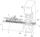
Fig. 1 is a schematic view of the overall structure of the present invention.
Fig. 2 is a top view of the abutment of the present invention.
Fig. 3 is a schematic structural diagram of the feeding assembly of the present invention.
Fig. 4 is a schematic structural view of a first hydraulic cylinder according to the present invention.
FIG. 5 is a schematic diagram of a moving plate structure according to the present invention.
FIG. 6 is a schematic structural diagram of a second hydraulic cylinder according to the present invention.
Fig. 7 is a schematic view of the structure of the material taking frame of the present invention.
FIG. 8 is a schematic view of a transfer module according to the present invention.
FIG. 9 is a schematic view of the wheel assembly of the present invention.
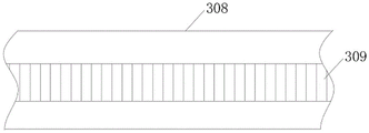
FIG. 10 is a schematic view of a partial structure of the power transmission belt of the present invention.
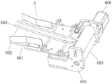
FIG. 11 is a schematic view of the waste ejector assembly of the present invention.
In the figure: 1. a base station; 101. a groove; 102. a first motor; 103. a first gear; 104. a support frame; 2. a feeding assembly; 201. a support pillar; 202. a first support plate; 203. a base plate; 204. a slide rail; 205. a first hydraulic cylinder; 206. a first hydraulic lever; 207. moving the plate; 208. a slider; 209. a slide hole; 210. a slide bar; 211. a connecting plate; 212. a lifting frame; 213. a second hydraulic cylinder; 214. a second hydraulic rod; 215. a lifting plate; 216. a material taking frame; 217. mounting a plate; 218. an electric suction cup; 3. a transfer assembly; 301. a cross beam; 302. a supporting strip; 303. a rotating wheel; 304. a wheel set; 305. rotating the rod; 306. a transfer wheel; 307. a second gear; 308. a transmission belt; 309. a tooth socket; 310. a stopper; 4. a support table; 401. a punching stage; 402. punching a groove; 403. a material taking port; 5. a stamping assembly; 501. a third hydraulic cylinder; 502. a third hydraulic lever; 503. punching a head; 6. a waste discharge assembly; 601. a discharge plate; 602. a guard plate; 603. a height limiting pressure lever; 604. a second support plate; 605. a rotating drum; 606. a second motor.
Detailed Description
In order to make the technical means, the creation characteristics, the achievement purposes and the effects of the invention easy to understand, the invention is further described with the specific embodiments.
As shown in fig. 1-11, the production equipment for the scooter base comprises a base platform 1, a feeding assembly 2, a conveying assembly 3, a supporting platform 4, a stamping assembly 5 and a waste discharging assembly 6, wherein the feeding assembly 2 is fixedly welded on one side of the base platform 1, the conveying assembly 3 is horizontally arranged on the top of the base platform 1, the conveying assembly 3 is positioned below the feeding assembly 2, one end of the base platform 1 is connected with the supporting platform 4, the stamping assembly 5 is fixedly welded on one side of the supporting platform 4, and the waste discharging assembly 6 is arranged on the top of one end, far away from the base platform 1, of the supporting platform 4;
the top of the base platform 1 is provided with three parallel grooves 101, a first motor 102 is horizontally installed in the groove 101 on one side close to one side of the base platform 1, one end of the first motor 102 is connected with a first gear 103 through a rotating shaft, the first gear 103 is rotatably matched in the middle groove 101, and the top of the base platform 1 is fixed with a plurality of supporting frames 104;
the feeding component 2 comprises supporting columns 201, first supporting plates 202 and material taking frames 216, wherein the two supporting columns 201 are vertically welded on one side of a base platform 1, the first supporting plates 202 are horizontally welded on the tops of the two supporting columns 201, the first supporting plates 202 and the two supporting columns 201 are integrally in an inverted U-shaped structure, two bottom plates 203 are horizontally welded on the tops of the first supporting plates 202, slide rails 204 are horizontally welded on the tops of the two bottom plates 203, a moving plate 207 is slidably matched on the two slide rails 204, a second hydraulic cylinder 213 is vertically installed on the top of the moving plate 207, a second hydraulic cylinder 214 is arranged at the bottom of the second hydraulic cylinder 213, one end, far away from the second hydraulic cylinder 213, of the second hydraulic cylinder 214 is connected with a lifting plate 215, a lifting frame 212 is horizontally installed at the bottom end of the lifting plate 215 through bolts, a plurality of material taking frames 216 are installed at equal intervals at the bottom of the lifting frame 212, the adsorption of the feeding component 2 of the production equipment to the raw material steel plate is firmer, so that the use reliability of the production equipment is further improved, meanwhile, the possibility of falling of the raw material steel plate in the feeding process is reduced by improving the adsorption firmness degree of the feeding component 2 to the raw material steel plate, so that the use safety of the production equipment is improved, the first hydraulic cylinder 205 is horizontally arranged at the top of the first supporting plate 202, the first hydraulic rod 206 is arranged at one end of the first hydraulic cylinder 205 close to the moving plate 207, one end of the first hydraulic rod 206 far away from the first hydraulic cylinder 205 is fixedly connected with one end of the moving plate 207, the automatic feeding function of the production equipment is realized by using the feeding component 2, so that the automation degree of the production equipment is improved, a large amount of manpower is saved by automatically feeding the production equipment, and the danger of manually moving and feeding is also reduced, thereby improving the safety of the production equipment in use, simultaneously, the loading operation of the equipment is more continuous and durable through automatic loading, thereby improving the production efficiency and the production capacity of the production equipment, and the material taking frame 216 can move up and down and back and forth by using the first hydraulic cylinder 205 and the second hydraulic cylinder 213 for driving, thereby improving the flexibility of the production equipment, leading the production equipment to transfer and take the raw material steel plate in the front-back range by moving the material taking frame 216 back and forth, by moving the material taking frame 216 up and down, the production equipment can suck the raw material steel plates from different heights, the operation range of material taking of the production equipment is more flexible and wider, so that the production equipment is beneficial to matching operation with other raw material supply equipment, and the compatibility of the production equipment and the cooperation capability between the production equipment and other equipment are improved;
the conveying assembly 3 comprises cross beams 301, supporting strips 302 and wheel sets 304, the two cross beams 301 are horizontally welded and fixed at the tops of a plurality of supporting frames 104, the supporting strips 302 are welded on one opposite sides of the two cross beams 301, a plurality of rotating wheels 303 are in equal-interval rotating fit at the tops of the two supporting strips 302, and the rotating wheels 303 are in rotating fit on the supporting strips 302, so that the raw material steel plate of the base of the processing plate trailer can move more smoothly on the conveying assembly 3, the reliability of the processing and production of the production equipment is further improved, meanwhile, the raw material steel plate is limited by the rotating wheels 303, the raw material steel plate is prevented from deviating towards two sides in the conveying process, the abrasion of the two sides of the raw material steel plate to the equipment in the conveying process is reduced, a protective effect is achieved on the production equipment, the service life of the production equipment is prolonged, a plurality of wheel sets 304 are in equal-interval rotating fit between the two supporting strips 302, the plurality of wheel sets 304 and the first gear 103 are sleeved with the transmission belt 308, and the plurality of wheel sets 304 are driven by the first motor 102 to rotate, so that the raw material steel plate is transmitted, the production equipment can automatically send the raw material to a processing area, the contact between an operator and the processing operation area is reduced, and the use safety of the production equipment is further improved;
the interior of the supporting table 4 is of a hollow structure, a material taking port 403 is formed in one side of the supporting table 4, a punching table 401 is fixed at the top of the supporting table 4, a punching groove 402 is formed in the top of the punching table 401, the punching groove 402 is communicated with the interior of the supporting table 4, the supporting table 4 is hollow, and the punching groove 402 is communicated with the interior of the supporting table 4, so that a product processed by the equipment can automatically fall from a processing area and can be automatically collected, the time and the danger of taking the product from the processing area are reduced, and the use efficiency and the safety of the production equipment are improved;
a third hydraulic cylinder 501 is vertically arranged on one side of the top of the stamping assembly 5, a third hydraulic rod 502 is arranged at the bottom of the third hydraulic cylinder 501, a stamping head 503 is arranged at the bottom of the third hydraulic rod 502, a bump matched with the stamping groove 402 is arranged at the bottom of the stamping head 503, and the stamping head 503 is driven by the third hydraulic cylinder 501 to stamp the raw material steel plate, so that the pallet base is processed;
the waste discharging component 6 comprises a discharging plate 601, a guard plate 602 and second supporting plates 604, the discharging plate 601 is welded at one end of the top of the supporting platform 4, the guard plates 602 are welded at both sides of the discharging plate 601, a height limiting pressure rod 603 is obliquely arranged at the top of the discharging plate 601, the two second supporting plates 604 are welded at one end of the supporting platform 4 far away from the conveying component 3, two rotary drums 605 are rotatably matched between the two second supporting plates 604, one side of one second supporting plate 604 far away from the rotary drum 605 is horizontally provided with a second motor 606, the second motor 606 is connected with one rotary drum 605 through a rotary shaft, through the arrangement of the waste discharging component 6, a steel plate punched out of the base of the plate trailer can be discharged, so that convenience is brought to collection and recycling of waste after production and processing, thereby the convenience of the use of the production equipment is improved, through the arrangement of the guard plate 602, the corner waste of the steel plate is prevented from falling from both sides, therefore, trouble is brought to the picking work, the corner waste of the tilted steel plate can be better guided to the two rotary drums 605 by arranging the height limiting pressing rod 603, and the corner waste is driven by the second motor 606 and is rotated, drawn and taken out by the two rotary drums 605.
The two bottom plates 203 are arranged in parallel. And two bottom plates 203 are all perpendicular with first backup pad 202, and the one end and the first backup pad 202 top welding of two bottom plate 203 bottoms, two bottom plates 203 all are located the top of base station 1.
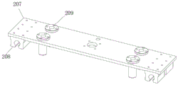
The two ends of the bottom of the moving plate 207 are welded with a row of sliding blocks 208, the two rows of sliding blocks 208 are respectively in sliding fit with the two sliding rails 204, the moving plate 207 is in sliding fit with the two sliding rails 204 through the two rows of sliding blocks 208, and the moving plate 207 moves more smoothly through the sliding fit of the sliding blocks 208 and the sliding rails 204.
The cross sections of the two slide rails 204 are both in an omega-shaped structure, the bottoms of the two rows of slide blocks 208 are both provided with slide grooves, the size of the cross sections of the slide grooves is matched with that of the cross sections of the slide rails 204, and the two rows of slide blocks 208 are respectively matched on the slide rails 204 in a sliding manner through the two rows of slide grooves.
Move the both ends at board 207 top and all seted up two slide opening 209, it has slide bar 210 to move equal sliding fit in two slide opening 209 at every end of board 207, the bottom of moving two slide bars 210 at every end of board 207 has all welded connecting plate 211, the bottom of two connecting plates 211 all welds with crane 212 top, through using slide bar 210 sliding fit in slide opening 209, it is more steady to make this equipment mention the in-process of raw and other materials steel sheet, and then improve the stability of this production facility material loading, it is stable through making this equipment material loading, thereby the reliability that this production facility used has been improved.
The material taking frame 216 comprises a mounting plate 217 and electric suckers 218 (model: BLSK-JGZ; manufacturer: BLSK), the mounting plate 217 is fixedly welded at the bottom of the lifting frame 212, the two electric suckers 218 are mounted at the bottom of the mounting plate 217 through bolts, the two electric suckers 218 are respectively located at two ends of the bottom of the mounting plate 217, the electric suckers 218 are driven by electric power to generate vacuum suction force, the raw material steel plate is sucked up, and the electric suckers 218 are mounted through the bolts, so that the electric suckers 218 are more convenient to replace.
The welding of base station 1 top has dog 310, and dog 310 is located the one end that the brace table 4 was kept away from to conveying assembly 3, through setting up dog 310, avoids artificial operation improper, causes conveying assembly 3 reverse conveying, leads to the reverse departure of raw and other materials steel sheet to hinder the people to further improve the security and the reliability that this production facility used.
The inner ring of the driving belt 308 is provided with tooth grooves 309, and the driving belt 308 is respectively meshed with the plurality of second gears 307 and the first gear 103 through the tooth grooves 309.
The production process of the production equipment specifically comprises the following steps:
the method comprises the following steps: the first hydraulic rod 206 is driven by the first hydraulic cylinder 205 to move, the first hydraulic rod 206 drives the moving plate 207, the moving plate 207 moves back and forth on the two slide rails 204, the front and back positions of the material taking frame 216 are adjusted by moving the moving plate 207 back and forth, the second hydraulic rod 214 is driven by the second hydraulic cylinder 213 to move, the second hydraulic rod 214 drives the lifting frame 212 to move the lifting frame 212 up and down, the height of the material taking frame 216 is adjusted by moving the lifting frame 212 up and down, the material taking frame 216 is moved onto a raw material steel plate by adjusting the front and back positions and the height of the material taking frame 216, one raw material steel plate is sucked by the material taking frame 216, and the steel plate sucked by the material taking frame 216 is placed on the conveying assembly 3 by adjusting the front and back positions and the height of the material taking frame 216;
step two: the first gear 103 is driven to rotate by the first motor 102, the first gear 103 is meshed with the tooth grooves 309 by rotating the first gear 103, the transmission belt 308 is driven to rotate, the transmission belt 308 drives the plurality of wheel sets 304 to rotate by the plurality of second gears 307, the raw material steel plate placed on the transmission assembly 3 is transmitted by rotating the plurality of wheel sets 304, and the raw material steel plate is transmitted to the top of the support table 4;
step three: the third hydraulic cylinder 501 drives the third hydraulic rod 502 to move, the third hydraulic rod 502 drives the punch 503 to punch downwards, the punch 503 punches downwards to punch the lath base with the shape of the lower punching groove 402 from the raw material steel plate, the lath base with the shape of the punching groove 402 falls into the support platform 4 through the punching groove 402, and the machined lath base is taken out through the material taking port 403 on one side of the support platform 4.
When the automatic feeding device is used, firstly, the first hydraulic cylinder 205 drives the first hydraulic rod 206 to move, the first hydraulic rod 206 drives the moving plate 207, the moving plate 207 moves back and forth on the two slide rails 204, the front and back positions of the material taking frame 216 are adjusted by moving the moving plate 207 back and forth, the second hydraulic cylinder 213 drives the second hydraulic rod 214 to move, the second hydraulic rod 214 drives the lifting frame 212 to move the lifting frame 212 up and down, the height of the material taking frame 216 is adjusted by moving the lifting frame 212 up and down, the front and back positions and the height of the material taking frame 216 are adjusted, the material taking frame 216 is moved onto a raw material steel plate, one raw material steel plate is sucked up by the material taking frame 216, the steel plate sucked up by the material taking frame 216 is placed on the conveying assembly 3 by adjusting the front and back positions and the height of the material taking frame 216, and the automatic feeding function of the production equipment is realized by using the feeding assembly 2, thereby improving the automation degree of the production equipment, saving a large amount of manpower by automatically feeding the production equipment, reducing the danger of manually carrying and lifting the materials, improving the safety of the production equipment in use, simultaneously enabling the feeding operation of the equipment to be more coherent and lasting by automatically feeding, improving the production efficiency and the production capacity of the production equipment, enabling the material taking frame 216 to move up and down and back and forth by driving through the first hydraulic cylinder 205 and the second hydraulic cylinder 213, improving the flexibility of the production equipment in use, enabling the production equipment to take and transfer the raw material steel plates in the front and back range by moving the material taking frame 216 back and forth, enabling the production equipment to suck the raw material steel plates from different heights by moving the material taking frame 216 up and down, further enabling the operation range of the production equipment to take materials to be more flexible and wide, thereby being helpful for the production equipment to match with other raw material supply equipment, thereby improving the compatibility of the production equipment and the cooperation capacity between the production equipment and other equipment, enabling the equipment to be more stable in the process of lifting the raw material steel plate by using the sliding rod 210 to be in sliding fit in the sliding hole 209, further improving the feeding stability of the production equipment, improving the use reliability of the production equipment by enabling the equipment to be stably fed, enabling the feeding assembly 2 of the production equipment to more firmly adsorb the raw material steel plate by arranging a plurality of material taking frames 216, further improving the use reliability of the production equipment, simultaneously reducing the possibility that the raw material steel plate falls off in the feeding process by improving the firmness degree of the feeding assembly 2 adsorbing the raw material steel plate, thereby improving the use safety of the production equipment, and then being driven by the first motor 102, the first gear 103 is rotated, the first gear 103 is meshed with the tooth spaces 309 by rotating the first gear 103, the transmission belt 308 is driven, the transmission belt 308 drives the plurality of wheel sets 304 to rotate through the plurality of second gears 307, the raw material steel plate placed on the transmission assembly 3 is transmitted by rotating the plurality of wheel sets 304, the raw material steel plate is transmitted to the top of the support table 4, the plurality of wheel sets 304 are rotated by driving through the first motor 102, the raw material steel plate is further transmitted, the production equipment can automatically transmit the raw material to a processing area, the contact between an operator and the processing operation area is reduced, the use safety of the production equipment is further improved, the raw material steel plate is transmitted through the plurality of wheel sets 304, the plurality of wheel sets 304 support the raw material steel plate through the two transmission wheels 306 at two ends, and the contact between the transmission assembly 3 and the middle area of the raw material steel plate is avoided, thereby reducing the abrasion of the middle taking part of the raw material steel plate, further improving the quality of the scooter plate trailer base processed by the production equipment, ensuring that the raw material steel plate for processing the scooter plate trailer base moves more smoothly on the conveying component 3 by rotating and matching a plurality of rotating wheels 303 on the supporting strip 302, further improving the processing and production reliability of the production equipment, simultaneously limiting the raw material steel plate through the rotating wheels 303, avoiding the raw material steel plate from deviating to two sides in the conveying process, reducing the abrasion of the two sides of the raw material steel plate to the equipment in the conveying process, playing a protection role for the production equipment, prolonging the service life of the production equipment, avoiding improper manual operation by arranging a stop block 310, causing the conveying component 3 to convey reversely, leading the raw material steel plate to fly out reversely to hurt people, further improving the use safety and reliability of the production equipment, finally, the third hydraulic cylinder 501 drives the third hydraulic rod 502 to move, the third hydraulic rod 502 drives the punch 503 to punch downwards, the punch 503 punches downwards to punch the lath base with the shape of the lower punching groove 402 from the raw steel plate, the lath base with the shape of the punching groove 402 falls into the support table 4 through the punching groove 402, the machined lath base is taken out through the material taking port 403 at one side of the support table 4, the third hydraulic cylinder 501 drives the punch 503 to punch the raw steel plate, so that the lath base is machined, the support table 4 is hollow, and the punching groove 402 is communicated with the support table 4, so that the product machined by the equipment can automatically fall from the machining area and realize automatic collection, thereby reducing the time and danger of taking the product from the machining area, and improving the use efficiency and safety of the production equipment, through setting up the waste discharge subassembly 6, can discharge the steel sheet of punching press out the wooden handcart base, and then for the collection and the recycle of production and processing back waste material bring facility, thereby the convenience that this production facility used has been improved, through setting up backplate 602, avoid the corner waste material of steel sheet to drop from both sides, thereby it is troublesome to bring for the work of picking up, through setting up limit for height depression bar 603, can be better with the corner waste material of perk steel sheet to two rotary drums 605 guides, thereby drive through second motor 606, rotate the traction and take out by two rotary drums 605.
The foregoing illustrates and describes the principles, general features, and advantages of the present invention. It will be understood by those skilled in the art that the present invention is not limited to the embodiments described above, and the embodiments and descriptions given above are only illustrative of the principles of the present invention, and various changes and modifications may be made without departing from the spirit and scope of the invention, which fall within the scope of the claims. The scope of the invention is defined by the appended claims and equivalents thereof.
Claims (10)
1. The utility model provides a production facility of scooter wooden handcart base, includes base station (1), material loading subassembly (2), conveying component (3), brace table (4), punching press subassembly (5) and waste discharge subassembly (6), its characterized in that: a feeding assembly (2) is fixedly welded on one side of the base platform (1), a conveying assembly (3) is horizontally arranged at the top of the base platform (1), the conveying assembly (3) is positioned below the feeding assembly (2), one end of the base platform (1) is connected with a supporting platform (4), a stamping assembly (5) is fixedly welded on one side of the supporting platform (4), and a waste discharging assembly (6) is arranged at the top of one end, far away from the base platform (1), of the supporting platform (4);
the top of the base platform (1) is provided with three parallel grooves (101), a first motor (102) is horizontally installed in one groove (101) on one side close to one side of the base platform (1), one end of the first motor (102) is connected with a first gear (103) through a rotating shaft, the first gear (103) is rotatably matched in the middle groove (101), and the top of the base platform (1) is fixedly provided with a plurality of supporting frames (104);
the feeding assembly (2) comprises a supporting column (201), a first supporting plate (202) and a material taking frame (216), wherein the supporting column (201) is vertically welded on one side of a base station (1), the first supporting plate (202) is horizontally welded on the top of the supporting column (201), the first supporting plate (202) and the two supporting columns (201) are integrally of an inverted U-shaped structure, the top of the first supporting plate (202) is horizontally welded with two bottom plates (203), the tops of the two bottom plates (203) are horizontally welded with sliding rails (204), the two sliding rails (204) are slidably matched with a moving plate (207), a second hydraulic cylinder (213) is vertically installed at the top of the moving plate (207), a second hydraulic cylinder (214) is arranged at the bottom of the second hydraulic cylinder (213), and one end, far away from the second hydraulic cylinder (213), of the second hydraulic cylinder (214) is connected with a lifting plate (215), a lifting frame (212) is horizontally arranged at the bottom end of the lifting plate (215) through bolts, a plurality of material taking frames (216) are arranged at equal intervals at the bottom of the lifting frame (212), a first hydraulic cylinder (205) is horizontally arranged at the top of the first supporting plate (202), a first hydraulic rod (206) is arranged at one end, close to the moving plate (207), of the first hydraulic cylinder (205), and one end, far away from the first hydraulic cylinder (205), of the first hydraulic rod (206) is fixedly connected with one end of the moving plate (207);
the conveying assembly (3) comprises cross beams (301), supporting strips (302) and wheel sets (304), the two cross beams (301) are horizontally welded and fixed to the tops of a plurality of supporting frames (104), the supporting strips (302) are welded on one opposite sides of the two cross beams (301), a plurality of rotating wheels (303) are in equal-interval rotating fit with the tops of the two supporting strips (302), a plurality of wheel sets (304) are in equal-interval rotating fit between the two supporting strips (302), and a driving belt (308) is sleeved on the plurality of wheel sets (304) and the first gear (103);
the interior of the supporting platform (4) is of a hollow structure, a material taking port (403) is formed in one side of the supporting platform (4), a punching platform (401) is fixed to the top of the supporting platform (4), a punching groove (402) is formed in the top of the punching platform (401), and the punching groove (402) is communicated with the interior of the supporting platform (4);
a third hydraulic cylinder (501) is vertically arranged on one side of the top of the stamping assembly (5), a third hydraulic rod (502) is arranged at the bottom of the third hydraulic cylinder (501), a stamping head (503) is mounted at the bottom of the third hydraulic rod (502), and a convex block matched with the stamping groove (402) is arranged at the bottom of the stamping head (503);
the waste discharging assembly (6) comprises a discharging plate (601), a protection plate (602) and second supporting plates (604), the discharging plate (601) is welded at one end of the top of a supporting table (4), the protection plate (602) is welded on two sides of the discharging plate (601), a height limiting pressure rod (603) is obliquely arranged on the top of the discharging plate (601), the second supporting plates (604) are welded at one end, far away from the conveying assembly (3), of the supporting table (4), two rotary drums (605) are rotatably matched between the second supporting plates (604), one side, far away from the rotary drums (605), of each second supporting plate (604) is horizontally provided with a second motor (606), and the second motor (606) is connected with one rotary drum (605) through a rotating shaft.
2. The scooter of claim 1 wherein the apparatus for producing a scooter platform comprises: two bottom plates (203) are parallel arrangement, and two bottom plates (203) all are perpendicular with first backup pad (202), and the one end and the first backup pad (202) top welding of two bottom plates (203) bottom, two bottom plates (203) all are located the top of base station (1).
3. The scooter of claim 1 wherein the apparatus for producing a scooter platform comprises: two ends of the bottom of the moving plate (207) are respectively welded with a row of sliding blocks (208), the two rows of sliding blocks (208) are respectively in sliding fit with the two sliding rails (204), and the moving plate (207) is in sliding fit with the two sliding rails (204) through the two rows of sliding blocks (208).
4. The scooter of claim 3 wherein the apparatus for producing the scooter's chassis comprises: the cross sections of the two sliding rails (204) are in omega-shaped structures, sliding grooves are formed in the bottoms of the two rows of sliding blocks (208), the size of the cross section of each sliding groove is matched with that of the cross section of each sliding rail (204), and the two rows of sliding blocks (208) are respectively in sliding fit with the sliding rails (204) through the two rows of sliding grooves.
5. The scooter of claim 1 wherein the apparatus for producing a scooter platform comprises: two sliding holes (209) are formed in two ends of the top of the moving plate (207), sliding rods (210) are arranged in the two sliding holes (209) at each end of the moving plate (207) in a sliding fit mode, connecting plates (211) are welded to the bottoms of the two sliding rods (210) at each end of the moving plate (207), and the bottoms of the two connecting plates (211) are welded to the top of the lifting frame (212).
6. The scooter of claim 1 wherein the apparatus for producing a scooter platform comprises: the material taking frame (216) comprises a mounting plate (217) and electric suckers (218), the mounting plate (217) is welded and fixed at the bottom of the lifting frame (212), the two electric suckers (218) are mounted at the bottom of the mounting plate (217) through bolts, and the two electric suckers (218) are respectively located at two ends of the bottom of the mounting plate (217).
7. The scooter of claim 1 wherein the apparatus for producing a scooter platform comprises: a stop block (310) is welded at the top of the base platform (1), and the stop block (310) is located at one end, far away from the support platform (4), of the conveying assembly (3).
8. The scooter of claim 1 wherein the apparatus for producing a scooter platform comprises: the wheel set (304) comprises a rotating rod (305), a transmission wheel (306) and a second gear (307), the rotating rod (305) is in running fit between the two support strips (302), the two transmission wheels (306) are respectively installed at two ends of the rotating rod (305), and the second gear (307) penetrates through and is fixed in the middle of the rotating rod (305).
9. The apparatus of claim 8, wherein: the inner ring of the transmission belt (308) is provided with tooth grooves (309), and the transmission belt (308) is respectively meshed with the second gears (307) and the first gear (103) through the tooth grooves (309).
10. A scooter base production apparatus as claimed in any one of claims 1 to 9, wherein: the production process of the production equipment specifically comprises the following steps:
the method comprises the following steps: the first hydraulic rod (206) is driven by the first hydraulic cylinder (205) to move, the first hydraulic rod (206) drives the moving plate (207) to move the moving plate (207) back and forth on the two slide rails (204), and the moving plate (207) is moved back and forth by the back and forth movement, the front and back positions of the material taking frame (216) are adjusted, the second hydraulic cylinder (213) drives the second hydraulic rod (214) to move, the second hydraulic rod (214) drives the lifting frame (212) to move the lifting frame (212) up and down, and the lifting frame (212) is moved up and down, the height of the material taking frame (216) is adjusted, the material taking frame (216) is moved to the position above the raw material steel plate by adjusting the front and back positions and the height of the material taking frame (216), a raw material steel plate is sucked up through the material taking frame (216), and the steel plate sucked up by the material taking frame (216) is placed on the conveying assembly (3) by adjusting the front and back positions and the height of the material taking frame (216);
step two: the first gear (103) is driven to rotate by the first motor (102), the first gear (103) is meshed with the tooth grooves (309) by rotating the first gear (103), the transmission belt (308) is driven, the transmission belt (308) drives the plurality of wheel sets (304) to rotate by the plurality of second gears (307), the raw material steel plate placed on the transmission assembly (3) is transmitted by rotating the plurality of wheel sets (304), and the raw material steel plate is transmitted to the top of the support table (4);
step three: the third hydraulic rod (502) is driven by the third hydraulic cylinder (501) to move, the third hydraulic rod (502) drives the stamping head (503) to stamp downwards, the stamping head (503) stamps downwards, the lathing base in the shape of the lower stamping groove (402) is stamped from the raw material steel plate, the lathing base in the shape of the stamping groove (402) falls into the supporting table (4) through the stamping groove (402), and the machined lathing base is taken out through the material taking hole (403) on one side of the supporting table (4).
Priority Applications (1)
| Application Number | Priority Date | Filing Date | Title |
|---|---|---|---|
| CN202111064960.0A CN113695444A (en) | 2021-09-11 | 2021-09-11 | Production equipment and production process of scooter base |
Applications Claiming Priority (1)
| Application Number | Priority Date | Filing Date | Title |
|---|---|---|---|
| CN202111064960.0A CN113695444A (en) | 2021-09-11 | 2021-09-11 | Production equipment and production process of scooter base |
Publications (1)
| Publication Number | Publication Date |
|---|---|
| CN113695444A true CN113695444A (en) | 2021-11-26 |
Family
ID=78659924
Family Applications (1)
| Application Number | Title | Priority Date | Filing Date |
|---|---|---|---|
| CN202111064960.0A Pending CN113695444A (en) | 2021-09-11 | 2021-09-11 | Production equipment and production process of scooter base |
Country Status (1)
| Country | Link |
|---|---|
| CN (1) | CN113695444A (en) |
Cited By (1)
| Publication number | Priority date | Publication date | Assignee | Title |
|---|---|---|---|---|
| CN115283936A (en) * | 2022-07-29 | 2022-11-04 | 临沂大学 | Metal material plate machining equipment |
Citations (11)
| Publication number | Priority date | Publication date | Assignee | Title |
|---|---|---|---|---|
| CN102794375A (en) * | 2011-05-26 | 2012-11-28 | 宁波建欣精密模具有限公司 | Stator landing edge-free triangular waste conveyor for motor die |
| CN205989005U (en) * | 2016-08-08 | 2017-03-01 | 惠州市众信天成电子发展有限公司 | A kind of waste material collection device of hydraulic press |
| CN207071610U (en) * | 2017-07-06 | 2018-03-06 | 力野精密工业(深圳)有限公司 | Feeding and punching press one automation equipment |
| CN208099148U (en) * | 2018-04-23 | 2018-11-16 | 徐州百惠模具制造有限公司 | A kind of waste discharging device on mold |
| CN109047457A (en) * | 2018-09-07 | 2018-12-21 | 中科动力(福建)新能源汽车有限公司 | A kind of stamping device of the band without scrap (bridge) blanking and punching mold |
| CN110548804A (en) * | 2019-09-09 | 2019-12-10 | 台州蓝锐机电科技有限公司 | Stainless steel punching mesh processing and manufacturing method |
| CN111215507A (en) * | 2020-01-16 | 2020-06-02 | 宁国市金驰汽车零部件有限公司 | A equipment for panel stamping process |
| CN111604405A (en) * | 2020-06-02 | 2020-09-01 | 郑州铁路职业技术学院 | Automatic continuous stamping device of railway signal relay part |
| CN112705638A (en) * | 2020-12-11 | 2021-04-27 | 安徽强旭塑业科技有限公司 | Stamping device for battery case processing and stamping method thereof |
| CN213645487U (en) * | 2020-08-20 | 2021-07-09 | 苏州庆业精密机械有限公司 | Double-station flanging machine for die machining |
| CN213969590U (en) * | 2020-12-16 | 2021-08-17 | 苏州泰为精密机械有限公司 | Automatic feeding device of laser cutting machine |
-
2021
- 2021-09-11 CN CN202111064960.0A patent/CN113695444A/en active Pending
Patent Citations (11)
| Publication number | Priority date | Publication date | Assignee | Title |
|---|---|---|---|---|
| CN102794375A (en) * | 2011-05-26 | 2012-11-28 | 宁波建欣精密模具有限公司 | Stator landing edge-free triangular waste conveyor for motor die |
| CN205989005U (en) * | 2016-08-08 | 2017-03-01 | 惠州市众信天成电子发展有限公司 | A kind of waste material collection device of hydraulic press |
| CN207071610U (en) * | 2017-07-06 | 2018-03-06 | 力野精密工业(深圳)有限公司 | Feeding and punching press one automation equipment |
| CN208099148U (en) * | 2018-04-23 | 2018-11-16 | 徐州百惠模具制造有限公司 | A kind of waste discharging device on mold |
| CN109047457A (en) * | 2018-09-07 | 2018-12-21 | 中科动力(福建)新能源汽车有限公司 | A kind of stamping device of the band without scrap (bridge) blanking and punching mold |
| CN110548804A (en) * | 2019-09-09 | 2019-12-10 | 台州蓝锐机电科技有限公司 | Stainless steel punching mesh processing and manufacturing method |
| CN111215507A (en) * | 2020-01-16 | 2020-06-02 | 宁国市金驰汽车零部件有限公司 | A equipment for panel stamping process |
| CN111604405A (en) * | 2020-06-02 | 2020-09-01 | 郑州铁路职业技术学院 | Automatic continuous stamping device of railway signal relay part |
| CN213645487U (en) * | 2020-08-20 | 2021-07-09 | 苏州庆业精密机械有限公司 | Double-station flanging machine for die machining |
| CN112705638A (en) * | 2020-12-11 | 2021-04-27 | 安徽强旭塑业科技有限公司 | Stamping device for battery case processing and stamping method thereof |
| CN213969590U (en) * | 2020-12-16 | 2021-08-17 | 苏州泰为精密机械有限公司 | Automatic feeding device of laser cutting machine |
Cited By (2)
| Publication number | Priority date | Publication date | Assignee | Title |
|---|---|---|---|---|
| CN115283936A (en) * | 2022-07-29 | 2022-11-04 | 临沂大学 | Metal material plate machining equipment |
| CN115283936B (en) * | 2022-07-29 | 2024-03-12 | 临沂大学 | Machining equipment for metal material plate |
Similar Documents
| Publication | Publication Date | Title |
|---|---|---|
| WO2017071503A1 (en) | Smart multi-functional cutting system for suction moulding materials | |
| CN209867143U (en) | Stamping die for processing arched workpiece | |
| CN111390008A (en) | Metal gasket stamping device for machining | |
| CN112719419B (en) | Be used for metal plate to stamp in batches and tailor device | |
| CN108746336B (en) | Punching and bending device of automatic spring piece forming machine | |
| CN113695444A (en) | Production equipment and production process of scooter base | |
| CN210172630U (en) | Slitting shearing machine convenient for discharging materials and used for longitudinally shearing steel belt | |
| CN201493425U (en) | Full-automatic forging loading and unloading robot | |
| CN114769400A (en) | Efficient numerical control punch | |
| CN212238786U (en) | Novel punching machine is used in production of grid dish frame | |
| CN200948486Y (en) | Fish-eye fastener three-in-one riveting machine | |
| CN109693096B (en) | Rotor, bearing and retaining ring assembly device | |
| CN109759650B (en) | Special equipment for cutting inner ball cage of automobile | |
| CN115072420A (en) | Automatic die cutting machine | |
| CN111438262A (en) | Automatic cutting machine | |
| CN217095386U (en) | Stamping lathe for machine manufacturing | |
| CN218574743U (en) | Auto-feeding auto-parts stamping die | |
| CN115533444A (en) | Rolling equipment | |
| CN212495168U (en) | Gear forges and uses conveyer | |
| CN211993316U (en) | Printing packaging box production is with clear useless cutting device of automation | |
| CN212557165U (en) | Composite feeding system of full-automatic badge making machine | |
| CN106410263A (en) | Automatic production equipment of lithium battery busbar upper polar column | |
| CN111516953A (en) | Composite feeding system of full-automatic badge making machine | |
| CN113369399A (en) | Multi-station efficient stamping equipment | |
| CN214354434U (en) | Automatic punch press with automatic material transporting device |
Legal Events
| Date | Code | Title | Description |
|---|---|---|---|
| PB01 | Publication | ||
| PB01 | Publication | ||
| SE01 | Entry into force of request for substantive examination | ||
| SE01 | Entry into force of request for substantive examination |