CN112719419B - Be used for metal plate to stamp in batches and tailor device - Google Patents
Be used for metal plate to stamp in batches and tailor device Download PDFInfo
- Publication number
- CN112719419B CN112719419B CN202011592085.9A CN202011592085A CN112719419B CN 112719419 B CN112719419 B CN 112719419B CN 202011592085 A CN202011592085 A CN 202011592085A CN 112719419 B CN112719419 B CN 112719419B
- Authority
- CN
- China
- Prior art keywords
- frame
- rack
- plate
- fixing
- guide
- Prior art date
- Legal status (The legal status is an assumption and is not a legal conclusion. Google has not performed a legal analysis and makes no representation as to the accuracy of the status listed.)
- Active
Links
Images


Classifications
-
- B—PERFORMING OPERATIONS; TRANSPORTING
- B23—MACHINE TOOLS; METAL-WORKING NOT OTHERWISE PROVIDED FOR
- B23D—PLANING; SLOTTING; SHEARING; BROACHING; SAWING; FILING; SCRAPING; LIKE OPERATIONS FOR WORKING METAL BY REMOVING MATERIAL, NOT OTHERWISE PROVIDED FOR
- B23D27/00—Machines or devices for cutting by a nibbling action
-
- B—PERFORMING OPERATIONS; TRANSPORTING
- B23—MACHINE TOOLS; METAL-WORKING NOT OTHERWISE PROVIDED FOR
- B23D—PLANING; SLOTTING; SHEARING; BROACHING; SAWING; FILING; SCRAPING; LIKE OPERATIONS FOR WORKING METAL BY REMOVING MATERIAL, NOT OTHERWISE PROVIDED FOR
- B23D33/00—Accessories for shearing machines or shearing devices
- B23D33/02—Arrangements for holding, guiding, and/or feeding work during the operation
-
- B—PERFORMING OPERATIONS; TRANSPORTING
- B23—MACHINE TOOLS; METAL-WORKING NOT OTHERWISE PROVIDED FOR
- B23Q—DETAILS, COMPONENTS, OR ACCESSORIES FOR MACHINE TOOLS, e.g. ARRANGEMENTS FOR COPYING OR CONTROLLING; MACHINE TOOLS IN GENERAL CHARACTERISED BY THE CONSTRUCTION OF PARTICULAR DETAILS OR COMPONENTS; COMBINATIONS OR ASSOCIATIONS OF METAL-WORKING MACHINES, NOT DIRECTED TO A PARTICULAR RESULT
- B23Q11/00—Accessories fitted to machine tools for keeping tools or parts of the machine in good working condition or for cooling work; Safety devices specially combined with or arranged in, or specially adapted for use in connection with, machine tools
- B23Q11/0042—Devices for removing chips
-
- B—PERFORMING OPERATIONS; TRANSPORTING
- B23—MACHINE TOOLS; METAL-WORKING NOT OTHERWISE PROVIDED FOR
- B23Q—DETAILS, COMPONENTS, OR ACCESSORIES FOR MACHINE TOOLS, e.g. ARRANGEMENTS FOR COPYING OR CONTROLLING; MACHINE TOOLS IN GENERAL CHARACTERISED BY THE CONSTRUCTION OF PARTICULAR DETAILS OR COMPONENTS; COMBINATIONS OR ASSOCIATIONS OF METAL-WORKING MACHINES, NOT DIRECTED TO A PARTICULAR RESULT
- B23Q5/00—Driving or feeding mechanisms; Control arrangements therefor
- B23Q5/22—Feeding members carrying tools or work
- B23Q5/34—Feeding other members supporting tools or work, e.g. saddles, tool-slides, through mechanical transmission
Abstract
The invention relates to a punching and cutting device, in particular to a batch punching and cutting device for metal plates. The invention provides a batch stamping and cutting device for metal plates, which has higher precision and efficiency of cutting the metal plates and safer manual operation. A device for the batch stamping and cutting of metal plates, comprising: a mounting bracket connected to one side of the base plate; the driving mechanism is connected to one side of the mounting frame; the lifting mechanism is connected to the other side of the mounting rack; the blanking mechanism is connected to the lifting mechanism; the jacking mechanism is connected between the mounting frame and the blanking mechanism; the discharging mechanism is connected to the other side of the bottom plate; and the conveying mechanism is connected between the bottom plate and the discharging mechanism. The invention has the beneficial effects that: through the effect of actuating mechanism, elevating system, blanking mechanism, top position mechanism, drop feed mechanism and transport mechanism, people can carry out more accurate tailorring to the metal plate continuously.
Description
Technical Field
The invention relates to a punching and cutting device, in particular to a batch punching and cutting device for metal plates.
Background
In the production manufacture process of metal objects, the parts of some objects have certain specification proportion requirements, people are required to cut the metal plate to form corresponding specifications so as to meet the production requirements, at present, the price of the metal plate stamping cutting device on the market is generally expensive, the production cost is high, so that a plurality of people cut the metal plate through a manual handheld cutting machine, the operation is carried out due to the fact that manual errors easily cause certain deviation of the specification proportion of cutting the metal plate, and the metal plate is not suitable for cutting large batches of metal plates.
Therefore, it is urgent to design a device for punching and cutting metal plates in batches, which has high precision and efficiency of cutting metal plates and is safer in manual operation.
Disclosure of Invention
(1) Technical problem to be solved
The invention aims to overcome the defects that when a user cuts a metal plate by holding a cutting machine by hand, the quality of the metal plate is easily influenced due to errors of manual operation, and when the user directly contacts the metal plate, the user is easily injured due to burrs on the metal plate.
(2) Technical scheme
In order to solve the technical problem, the invention provides a device for batch stamping and cutting of metal plates, which comprises: a mounting bracket connected to one side of the base plate; the driving mechanism is connected to one side of the mounting frame; the lifting mechanism is connected to the other side of the mounting rack; the blanking mechanism is connected to the lifting mechanism; the jacking mechanism is connected between the mounting frame and the blanking mechanism; the discharging mechanism is connected to the other side of the bottom plate; and the conveying mechanism is connected between the bottom plate and the discharging mechanism.
Preferably, the drive mechanism comprises: the supporting frame is connected to the mounting frame; a low-speed motor mounted on the support frame; the limiting plate is connected to one side, close to the low-speed motor, of the supporting frame; and the rotating shaft is connected to the output shaft of the low-speed motor and is rotatably connected with the limiting plate.
Preferably, the elevating mechanism includes: a sector gear connected to the rotating shaft; the first guide sliding frame is connected to the mounting frame; a first carrier slidably coupled to the first guide; a guide rod connected to the first rack, the guide rod being slidably connected to the mounting bracket; and the first spring group is connected between the guide rod and the mounting frame.
Preferably, the blanking mechanism includes: the fixed rod is connected to the guide rod; the cutter is connected to the fixed rod; the second spring group is connected to one side of the fixing rod; and the pressure plate is connected to the second spring set.
Preferably, the jacking mechanism comprises: the wedge-shaped blocks are at least provided with two blocks and are connected to the cutter; the wedge-shaped block is matched with the first stop block; the first ejector blocks are at least provided with two first ejector blocks, the first ejector blocks are connected to the mounting frame in a sliding mode, and the first ejector blocks on the adjacent sides are matched with the wedge-shaped blocks; and the third spring group is connected between the first ejector block and the mounting frame.
Preferably, the drop feed mechanism comprises: the first fixing frame is connected to one side, close to the mounting frame, of the bottom plate; the workbench is connected to the first fixing frame; the discharging frame is connected to the workbench in a sliding manner; and at least two second stop blocks are arranged and are connected to the discharging frame.
Preferably, the transfer mechanism comprises: a second rack connected to one side of the cutter; the positioning plate is connected to the other side, close to the mounting frame, of the bottom plate; the power straight gear is rotatably connected to the positioning plate; the transmission straight gear is rotatably connected to one side, close to the power straight gear, of the positioning plate, the second rack is matched with the power straight gear, and a groove is formed in one side of the transmission straight gear; the second guide carriage is connected to one side of the workbench; and the third rack frame is connected to one side of the discharging frame, is connected with the second guide sliding frame in a sliding mode, and is meshed with the transmission straight gear.
Preferably, the device further comprises a clamping mechanism, wherein the clamping mechanism comprises: the fixing block is connected to one side, close to the transmission straight gear, of the positioning plate; the guide post is connected to the fixing block in a sliding mode and matched with the groove; and the tension spring is connected between the fixed block and the guide pillar.
Preferably, still include shedding mechanism, shedding mechanism includes: the second fixing frame is connected to one side, close to the positioning plate, of the bottom plate; the cylinder is connected to the second fixing frame; and the second ejector block is connected to the telescopic rod of the air cylinder.
Preferably, still including receiving mechanism, receiving mechanism includes: the oblique sliding frame is connected to the other side of the discharging frame; the third fixing frame is connected to one side, close to the second fixing frame, of the bottom plate; a waste receiving box connected to one side of the third fixing frame; and the material receiving box is connected to the other side of the third fixing frame.
(3) Advantageous effects
The invention has the beneficial effects that: through the action of the driving mechanism, the lifting mechanism, the blanking mechanism, the jacking mechanism, the discharging mechanism and the conveying mechanism, people can continuously realize more accurate cutting of the metal plate without needing to complete the cutting of the metal plate by holding the cutting machine by hands for many times, so that the efficiency of cutting the metal plate by people and the safety of operation are improved; through the action of the discharging mechanism and the receiving mechanism, the cut metal plates do not need to be taken out one by people, so that the cutting efficiency of the metal plates by people is further improved, and the labor intensity of manual operation is reduced; through the effect of screens mechanism for the accuracy that the metal plate was tailor is carried out to the further improvement to the steadiness that baiting frame and metal plate were more.
Drawings
Fig. 1 is a schematic perspective view of a first embodiment of the present invention.
Fig. 2 is a schematic perspective view of a second embodiment of the present invention.
Fig. 3 is a third perspective view of the present invention.
Fig. 4 is a schematic perspective view of the driving mechanism of the present invention.
Fig. 5 is a schematic perspective view of the lifting mechanism and the jacking mechanism of the present invention.
Fig. 6 is a schematic partial perspective view of the blanking mechanism of the present invention.
Fig. 7 is a schematic perspective view of the discharging mechanism of the present invention.
Fig. 8 is a schematic perspective view of the transfer mechanism of the present invention.
Fig. 9 is a schematic perspective view of the locking mechanism of the present invention.
Fig. 10 is a schematic perspective view of the discharging mechanism and the receiving mechanism of the present invention.
The labels in the figures are: 1-a bottom plate, 2-a mounting frame, 3-a driving mechanism, 31-a supporting frame, 32-a low-speed motor, 33-a limiting plate, 34-a rotating shaft, 4-a lifting mechanism, 41-a sector gear, 42-a first guide frame, 43-a guide rod, 44-a first rack frame, 45-a first spring set, 5-a blanking mechanism, 51-a fixed rod, 52-a cutter, 53-a pressing plate, 54-a second spring set, 6-a jacking mechanism, 61-a wedge block, 62-a first stop block, 63-a first top block, 64-a third spring set, 7-a discharging mechanism, 71-a first fixing frame, 72-a working platform, 73-a discharging frame, 74-a second stop block, 8-a conveying mechanism and 81-a second rack frame, 82-a positioning plate, 83-a second guide carriage, 84-a third rack, 85-a power spur gear, 86-a transmission spur gear, 9-a clamping mechanism, 91-a fixing block, 92-a guide post, 93-a tension spring, 10-a discharging mechanism, 101-a second fixing frame, 102-an air cylinder, 103-a second top block, 11-a material receiving mechanism, 1101-an inclined carriage, 1102-a third fixing frame, 1103-a waste material receiving box and 1104-a material receiving box.
Detailed Description
The invention is further described below with reference to the figures and examples.
Example 1
The utility model provides a be used for metal plate to cut out device in punching press in batches, as shown in fig. 1 to 8, including bottom plate 1, mounting bracket 2, actuating mechanism 3, elevating system 4, blanking mechanism 5, top position mechanism 6, drop feed mechanism 7 and transport mechanism 8, the rear side at 1 top of bottom plate is connected with mounting bracket 2, the rear side at 2 middle parts of mounting bracket is connected with actuating mechanism 3, the rear side on 2 upper portions of mounting bracket is connected with elevating system 4, be connected with blanking mechanism 5 on elevating system 4, be connected with top position mechanism 6 between the lower part of mounting bracket 2 and the blanking mechanism 5, the rear side at 1 middle part of bottom plate is connected with drop feed mechanism 7, be connected with transport mechanism 8 between the right side at 1 top of bottom plate and drop feed mechanism 7.
The driving mechanism 3 comprises a support frame 31, a low-speed motor 32, a limiting plate 33 and a rotating shaft 34, the support frame 31 is connected to the rear side of the middle of the mounting frame 2, the low-speed motor 32 is installed at the top of the support frame 31, the limiting plate 33 is connected to the left side of the support frame 31, the rotating shaft 34 is connected to an output shaft of the low-speed motor 32, and the rotating shaft 34 is connected with the limiting plate 33 in a rotating mode.
The lifting mechanism 4 comprises a sector gear 41, a first guide carriage 42, a guide rod 43, a first rack 44 and a first spring group 45, the sector gear 41 is connected to the rotating shaft 34, the first guide carriage 42 is connected to the upper portion of the mounting frame 2, the first rack 44 is connected to the first guide carriage 42 in a sliding mode, the guide rod 43 is connected to the lower portion of the first rack 44, the guide rod 43 is connected to the mounting frame 2 in a sliding mode, and the first spring group 45 is connected between the guide rod 43 and the inner top of the mounting frame 2.
The blanking mechanism 5 comprises a fixed rod 51, a cutter 52, a pressure plate 53 and a second spring group 54, the middle part of the guide rod 43 is connected with the fixed rod 51, the lower part of the fixed rod 51 is connected with the cutter 52, the bottom of the fixed rod 51 is connected with the second spring group 54, and the lower end of the second spring group 54 is connected with the pressure plate 53.
The top position mechanism 6 comprises a wedge block 61, a first stop block 62, a first top block 63 and a third spring group 64, the wedge block 61 is connected to the left side and the right side of the lower portion of the cutter 52, the first stop block 62 is connected to the left side and the right side of the outer side face of the middle of the mounting frame 2 in a bilateral symmetry mode, the wedge block 61 is matched with the first stop block 62, the first top block 63 is connected to the left side and the right side of the middle of the mounting frame 2 in a sliding mode, the first top block 63 on one adjacent side is matched with the wedge block 61, and the third spring group 64 is connected between the first top block 63 on one adjacent side and the mounting frame 2.
The discharging mechanism 7 comprises a first fixing frame 71, a workbench 72, a discharging frame 73 and a second stopper 74, the rear side of the middle part of the bottom plate 1 is connected with the first fixing frame 71, the upper part of the first fixing frame 71 is connected with the workbench 72, the workbench 72 is connected with the discharging frame 73 in a sliding mode, and the front side and the rear side of the discharging frame 73 are connected with the second stoppers 74.
The conveying mechanism 8 comprises a second rack 81, a positioning plate 82, a second guide carriage 83, a third rack 84, a power straight gear 85 and a transmission straight gear 86, the front side of the cutter 52 is connected with the second rack 81, the top of the bottom plate 1 is connected with the positioning plate 82, the positioning plate 82 is positioned on the left side of the first fixing frame 71, the upper part of the positioning plate 82 is rotatably connected with the power straight gear 85 and the transmission straight gear 86, the second rack 81 is matched with the power straight gear 85, two grooves are symmetrically formed in the right side surface of the transmission straight gear 86, the right side of the workbench 72 is connected with the second guide carriage 83, the right side of the discharge frame 73 is connected with the third rack 84, the third rack 84 is slidably connected with the second guide carriage 83, and the third rack 84 is meshed with the transmission straight gear 86.
In the production and manufacturing process of metal products, when people need to perform batch stamping and cutting on metal plates, the metal plates can be placed on the discharge frame 73 and positioned between the two second stop blocks 74, the low-speed motor 32 is started, the low-speed motor 32 drives the sector gear 41 to rotate along with the sector gear, when the sector gear 41 is meshed with the first rack frame 44, the guide rod 43 drives the fixed rod 51 and the cutter 52 to slide downwards along with the sector gear, the first spring group 45 is stretched along with the sector gear, when the second rack frame 81 is matched with the power straight gear 85, the transmission straight gear 86 drives the third rack frame 84 and the discharge frame 73 to slide backwards along with the sector gear, when the wedge block 61 is contacted with the first top block 63 and continues to slide downwards, the first top blocks 63 on the front side and the rear side slide towards the middle along with the sector gear, the third spring group 64 is stretched, and the metal plates are fixed along with the sector under the matching action of the first top blocks 63 and the second stop blocks 74, when the pressing plate 53 contacts with the metal plate and slides downwards continuously, the second spring group 54 is compressed therewith, the cutter 52 slides downwards continuously to perform stamping cutting on the metal plate, after the metal plate is cut, the cut waste is pushed onto the workbench 72 and is positioned in the discharging frame 73 under the action of the elastic force of the second spring group 54, when the sector gear 41 is separated from the first rack 44, the guide rod 43 and the cutter 52 are driven to slide upwards and reset under the action of the elastic force of the first spring group 45, the second rack 81 drives the power spur gear 85 and the transmission spur gear 86 to rotate reversely, the third rack 84 drives the discharging frame 73 and the metal plate to slide forwards and reset, the waste falls onto the bottom plate 1 under the pushing action of the discharging frame 73, the wedge 61 is separated from the first top block 63, the first top block 63 slides outwards and resets under the action of the elastic force of the third spring group 64, at this moment, people can take out the metal plate after cutting, only need repeat the above operation, so can be continuous realize carrying out more accurate cutting to the metal plate, need not to carry out many times through people handheld cutting machine and tailor the metal plate and accomplish, improve the efficiency that people cut to the metal plate and the security of operation.
Example 2
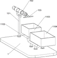
On the basis of embodiment 1, as shown in fig. 10, the discharging device 10 is further included, the discharging device 10 includes a second fixing frame 101, an air cylinder 102 and a second top block 103, the front side of the top of the bottom plate 1 is connected with the second fixing frame 101, the upper portion of the second fixing frame 101 is connected with the air cylinder 102, and the telescopic rod of the air cylinder 102 is connected with the second top block 103.
The material receiving mechanism 11 comprises an inclined sliding frame 1101, a third fixing frame 1102, a waste receiving box 1103 and a material receiving box 1104, the inclined sliding frame 1101 is connected to the left side of the discharging frame 73, the third fixing frame 1102 is connected to the front side of the top of the bottom plate 1, the third fixing frame 1102 is located on the rear side of the second fixing frame 101, the waste receiving box 1103 is connected to the front side of the upper portion of the third fixing frame 1102, and the material receiving box 1104 is connected to the rear side of the upper portion of the third fixing frame 1102.
When people need to take out the cut metal plate, the cylinder 102 is started to extend the telescopic rod of the cylinder, the second ejector block 103 pushes the cut metal plate into the material receiving box 1104 under the guiding action of the inclined sliding frame 1101, the cut metal plate does not need to be taken out one by people, the cutting efficiency of the metal plate by people is further improved, and the labor intensity of manual operation is reduced.
Example 3
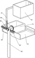
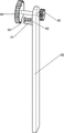
On the basis of the embodiment 2, as shown in fig. 9, the positioning device further includes a locking mechanism 9, the locking mechanism 9 includes a fixing block 91, a guide post 92 and a tension spring 93, the fixing block 91 is connected to the left side of the upper portion of the positioning plate 82, the guide post 92 is slidably connected to the fixing block 91, the guide post 92 is matched with the groove, and the tension spring 93 is connected between the fixing block 91 and the guide post 92.
Under the cooperation of guide pillar 92 and recess, make transmission spur gear 86 and third rack 84 keep certain stability when cutter 52 cuts the metal plate to indirect the more firm of blowing frame 73 and metal plate, further improvement is to the precision that the metal plate was cut out.
The above examples are merely representative of preferred embodiments of the present invention, and the description thereof is more specific and detailed, but not to be construed as limiting the scope of the present invention. It should be noted that, for those skilled in the art, various changes, modifications and substitutions can be made without departing from the spirit of the present invention, and these are all within the scope of the present invention. Therefore, the protection scope of the present patent shall be subject to the appended claims.
Claims (3)
1. The utility model provides a device is tailor for punching press in batches of metal plate which characterized in that includes:
a mounting rack (2) connected to one side of the base plate (1);
the driving mechanism (3) is connected to one side of the mounting frame (2);
the lifting mechanism (4) is connected to the other side of the mounting rack (2);
a blanking mechanism (5) connected to the lifting mechanism (4);
the jacking mechanism (6) is connected between the mounting frame (2) and the blanking mechanism (5);
the discharging mechanism (7) is connected to the other side of the bottom plate (1);
the conveying mechanism (8) is connected between the bottom plate (1) and the discharging mechanism (7);
the drive mechanism (3) includes:
a support frame (31) connected to the mounting frame (2);
a low-speed motor (32) mounted on the support frame (31);
the limiting plate (33) is connected to one side, close to the low-speed motor (32), of the support frame (31);
a rotating shaft (34) which is connected to the output shaft of the low-speed motor (32), and the rotating shaft (34) is rotatably connected with the limit plate (33);
the lifting mechanism (4) comprises:
a sector gear (41) connected to the rotating shaft (34);
a first guide frame (42) connected to the mounting frame (2);
a first rack (44) slidably connected to the first guide (42);
a guide rod (43) connected to the first rack (44), the guide rod (43) being slidably connected to the mounting bracket (2);
a first spring group (45) connected between the guide rod (43) and the mounting frame (2);
the blanking mechanism (5) includes:
a fixing rod (51) connected to the guide rod (43);
a cutter (52) connected to the fixing rod (51);
a second spring group (54) connected to one side of the fixing rod (51);
a pressure plate (53) connected to the second spring group (54);
the top position mechanism (6) comprises:
the wedge-shaped blocks (61) are at least provided with two blocks and are connected to the cutter (52);
the first stop blocks (62) are at least provided with two and are connected to one side of the mounting frame (2), and the wedge-shaped blocks (61) are matched with the first stop blocks (62);
the first ejector blocks (63) are at least provided with two, are connected to the mounting frame (2) in a sliding mode, and the first ejector blocks (63) on the adjacent sides are matched with the wedge-shaped blocks (61);
a third spring group (64) connected between the first top block (63) and the mounting frame (2);
drop feed mechanism (7) includes:
the first fixing frame (71) is connected to one side, close to the mounting frame (2), of the bottom plate (1);
a table (72) connected to the first holder (71);
a material placing frame (73) which is connected to the workbench (72) in a sliding manner;
at least two second stoppers (74) are arranged and are connected to the discharging frame (73);
the transfer mechanism (8) comprises:
a second rack (81) connected to one side of the cutter (52);
the positioning plate (82) is connected to the other side, close to the mounting frame (2), of the bottom plate (1);
a power straight gear (85) which is rotationally connected to the positioning plate (82);
the transmission straight gear (86) is rotatably connected to one side, close to the power straight gear (85), of the positioning plate (82), the second rack (81) is matched with the power straight gear (85), and a groove is formed in one side of the transmission straight gear (86);
a second guide frame (83) connected to one side of the table (72);
a third rack (84) connected to one side of the discharge frame (73), wherein the third rack (84) is slidably connected to the second guide frame (83), and the third rack (84) is meshed with a transmission spur gear (86);
still including screens mechanism (9), screens mechanism (9) include:
the fixing block (91) is connected to one side, close to the transmission straight gear (86), of the positioning plate (82);
the guide post (92) is connected to the fixing block (91) in a sliding mode, and the guide post (92) is matched with the groove;
a tension spring (93) connected between the fixing block (91) and the guide post (92);
under the mating reaction of guide pillar (92) and recess, make transmission spur gear (86) and third rack (84) keep certain stability when cutter (52) are tailor the metal plate to indirect make the material discharge frame (73) more firm with the metal plate, further improvement is to the precision that the metal plate was tailor.
2. A device for stamping and cutting metal plates in batches as claimed in claim 1, further comprising a discharge mechanism (10), wherein the discharge mechanism (10) comprises:
the second fixing frame (101) is connected to one side, close to the positioning plate (82), of the bottom plate (1);
a cylinder (102) connected to the second fixing frame (101);
and the second top block (103) is connected to the telescopic rod of the air cylinder (102).
3. The device for punching and cutting metal plates in batches according to claim 2, further comprising a material receiving mechanism (11), wherein the material receiving mechanism (11) comprises:
a skew carriage (1101) connected to the other side of the discharge frame (73);
the third fixing frame (1102) is connected to one side, close to the second fixing frame (101), of the bottom plate (1);
a waste receiving box (1103) connected to one side of the third fixing frame (1102);
and a material receiving box (1104) connected to the other side of the third fixing frame (1102).
Priority Applications (1)
| Application Number | Priority Date | Filing Date | Title |
|---|---|---|---|
| CN202011592085.9A CN112719419B (en) | 2020-12-29 | 2020-12-29 | Be used for metal plate to stamp in batches and tailor device |
Applications Claiming Priority (1)
| Application Number | Priority Date | Filing Date | Title |
|---|---|---|---|
| CN202011592085.9A CN112719419B (en) | 2020-12-29 | 2020-12-29 | Be used for metal plate to stamp in batches and tailor device |
Publications (2)
| Publication Number | Publication Date |
|---|---|
| CN112719419A CN112719419A (en) | 2021-04-30 |
| CN112719419B true CN112719419B (en) | 2022-08-09 |
Family
ID=75607697
Family Applications (1)
| Application Number | Title | Priority Date | Filing Date |
|---|---|---|---|
| CN202011592085.9A Active CN112719419B (en) | 2020-12-29 | 2020-12-29 | Be used for metal plate to stamp in batches and tailor device |
Country Status (1)
| Country | Link |
|---|---|
| CN (1) | CN112719419B (en) |
Families Citing this family (3)
| Publication number | Priority date | Publication date | Assignee | Title |
|---|---|---|---|---|
| CN113910373A (en) * | 2021-09-08 | 2022-01-11 | 刘艳婷 | Shell trimming device for high-end equipment |
| CN113967760B (en) * | 2021-11-24 | 2023-12-19 | 青岛张氏上佳科技有限公司 | Cutting device capable of being conveniently adjusted |
| CN114290068B (en) * | 2021-12-23 | 2023-04-14 | 南京劲拓机械有限公司 | Batch manufacturing device for gears |
Citations (7)
| Publication number | Priority date | Publication date | Assignee | Title |
|---|---|---|---|---|
| SU1238853A1 (en) * | 1985-01-28 | 1986-06-23 | Krivovyazyuk Anatoli S | Die for cutting off blanks from flat material |
| CN106079518A (en) * | 2016-08-01 | 2016-11-09 | 刘小波 | A kind of waste material rapid compression machine |
| CN106112099A (en) * | 2016-08-16 | 2016-11-16 | 温州市成尚装饰五金有限公司 | A kind of five metalworking aluminum product cutting devices |
| CN206643424U (en) * | 2017-04-25 | 2017-11-17 | 叶宝义 | A kind of handware efficient cutting |
| CN211388909U (en) * | 2019-12-23 | 2020-09-01 | 蚌埠大美印务有限公司 | Paper cutting device |
| CN111791276A (en) * | 2020-07-02 | 2020-10-20 | 钟永锋 | Automatic guillootine of silica gel goods |
| CN112094046A (en) * | 2020-08-18 | 2020-12-18 | 卢文苏 | Adjustable automatic cutting device for rectangular glass |
-
2020
- 2020-12-29 CN CN202011592085.9A patent/CN112719419B/en active Active
Patent Citations (7)
| Publication number | Priority date | Publication date | Assignee | Title |
|---|---|---|---|---|
| SU1238853A1 (en) * | 1985-01-28 | 1986-06-23 | Krivovyazyuk Anatoli S | Die for cutting off blanks from flat material |
| CN106079518A (en) * | 2016-08-01 | 2016-11-09 | 刘小波 | A kind of waste material rapid compression machine |
| CN106112099A (en) * | 2016-08-16 | 2016-11-16 | 温州市成尚装饰五金有限公司 | A kind of five metalworking aluminum product cutting devices |
| CN206643424U (en) * | 2017-04-25 | 2017-11-17 | 叶宝义 | A kind of handware efficient cutting |
| CN211388909U (en) * | 2019-12-23 | 2020-09-01 | 蚌埠大美印务有限公司 | Paper cutting device |
| CN111791276A (en) * | 2020-07-02 | 2020-10-20 | 钟永锋 | Automatic guillootine of silica gel goods |
| CN112094046A (en) * | 2020-08-18 | 2020-12-18 | 卢文苏 | Adjustable automatic cutting device for rectangular glass |
Also Published As
| Publication number | Publication date |
|---|---|
| CN112719419A (en) | 2021-04-30 |
Similar Documents
| Publication | Publication Date | Title |
|---|---|---|
| CN112719419B (en) | Be used for metal plate to stamp in batches and tailor device | |
| CN112620714A (en) | Drilling equipment is used in production of huge saw disc | |
| CN212264257U (en) | A full-automatic oil press for preparing high performance stainless steel knife, fork and spoon | |
| CN113276483A (en) | Packaging carton secondary recycling treatment method | |
| CN114904954B (en) | Fan blade stamping forming device | |
| CN116237773A (en) | Hardware connecting piece production equipment | |
| CN113695444A (en) | Production equipment and production process of scooter base | |
| CN112659254B (en) | Rubber pad part punching machine | |
| CN113059602B (en) | Gasket auxiliary trimming device for manufacturing high-end equipment | |
| CN211993316U (en) | Printing packaging box production is with clear useless cutting device of automation | |
| CN219211256U (en) | Punching machine capable of improving discharging efficiency | |
| CN220278047U (en) | Stamping die for automobile parts | |
| CN220680922U (en) | Wave-absorbing material cutting and pressing device | |
| CN113084246B (en) | Round iron sheet trimming device for workshop | |
| CN219052604U (en) | Road traffic sign board punching machine | |
| CN216397748U (en) | Workpiece manufacturing die for mechanical design | |
| CN217444432U (en) | Assembling machine for battery grounding piece | |
| CN214349052U (en) | New energy automobile panel stamping die | |
| CN215040647U (en) | Make things convenient for powder forming tablet press of ejection of compact | |
| CN215237055U (en) | Hole flanging die for plate hole forming | |
| CN112091677B (en) | Workpiece plane batch milling equipment | |
| CN217802123U (en) | Full-automatic protection film cross cutting machine | |
| CN218168437U (en) | Automatic carry sheet material mould | |
| CN113475547B (en) | Device is cut with knurling to cake production | |
| CN214393165U (en) | Sawing and milling processing system |
Legal Events
| Date | Code | Title | Description |
|---|---|---|---|
| PB01 | Publication | ||
| PB01 | Publication | ||
| SE01 | Entry into force of request for substantive examination | ||
| SE01 | Entry into force of request for substantive examination | ||
| TA01 | Transfer of patent application right | ||
| TA01 | Transfer of patent application right |
Effective date of registration: 20220719 Address after: 230000 No.1, intersection of Gaocheng road and Wenshan Road, Taohua Industrial Park, Feixi County, Hefei City, Anhui Province Applicant after: Hefei yichangxing Intelligent Technology Co.,Ltd. Address before: 211100 room 1218, building 9, No. 455, Jiuzhu Road, baijiahu, Jiangning District, Nanjing, Jiangsu Province Applicant before: Li Zhike |
|
| GR01 | Patent grant | ||
| GR01 | Patent grant |