CN113619856A - Connecting conveying line of straw production device - Google Patents
Connecting conveying line of straw production device Download PDFInfo
- Publication number
- CN113619856A CN113619856A CN202110927013.3A CN202110927013A CN113619856A CN 113619856 A CN113619856 A CN 113619856A CN 202110927013 A CN202110927013 A CN 202110927013A CN 113619856 A CN113619856 A CN 113619856A
- Authority
- CN
- China
- Prior art keywords
- conveying belt
- straw
- belt
- pipe
- straws
- Prior art date
- Legal status (The legal status is an assumption and is not a legal conclusion. Google has not performed a legal analysis and makes no representation as to the accuracy of the status listed.)
- Pending
Links
Images


Classifications
-
- B—PERFORMING OPERATIONS; TRANSPORTING
- B65—CONVEYING; PACKING; STORING; HANDLING THIN OR FILAMENTARY MATERIAL
- B65B—MACHINES, APPARATUS OR DEVICES FOR, OR METHODS OF, PACKAGING ARTICLES OR MATERIALS; UNPACKING
- B65B35/00—Supplying, feeding, arranging or orientating articles to be packaged
- B65B35/10—Feeding, e.g. conveying, single articles
- B65B35/24—Feeding, e.g. conveying, single articles by endless belts or chains
-
- B—PERFORMING OPERATIONS; TRANSPORTING
- B65—CONVEYING; PACKING; STORING; HANDLING THIN OR FILAMENTARY MATERIAL
- B65B—MACHINES, APPARATUS OR DEVICES FOR, OR METHODS OF, PACKAGING ARTICLES OR MATERIALS; UNPACKING
- B65B35/00—Supplying, feeding, arranging or orientating articles to be packaged
- B65B35/10—Feeding, e.g. conveying, single articles
- B65B35/20—Feeding, e.g. conveying, single articles by reciprocating or oscillatory pushers
-
- B—PERFORMING OPERATIONS; TRANSPORTING
- B65—CONVEYING; PACKING; STORING; HANDLING THIN OR FILAMENTARY MATERIAL
- B65B—MACHINES, APPARATUS OR DEVICES FOR, OR METHODS OF, PACKAGING ARTICLES OR MATERIALS; UNPACKING
- B65B35/00—Supplying, feeding, arranging or orientating articles to be packaged
- B65B35/30—Arranging and feeding articles in groups
- B65B35/40—Arranging and feeding articles in groups by reciprocating or oscillatory pushers
-
- B—PERFORMING OPERATIONS; TRANSPORTING
- B65—CONVEYING; PACKING; STORING; HANDLING THIN OR FILAMENTARY MATERIAL
- B65B—MACHINES, APPARATUS OR DEVICES FOR, OR METHODS OF, PACKAGING ARTICLES OR MATERIALS; UNPACKING
- B65B35/00—Supplying, feeding, arranging or orientating articles to be packaged
- B65B35/30—Arranging and feeding articles in groups
- B65B35/44—Arranging and feeding articles in groups by endless belts or chains
-
- B—PERFORMING OPERATIONS; TRANSPORTING
- B65—CONVEYING; PACKING; STORING; HANDLING THIN OR FILAMENTARY MATERIAL
- B65B—MACHINES, APPARATUS OR DEVICES FOR, OR METHODS OF, PACKAGING ARTICLES OR MATERIALS; UNPACKING
- B65B35/00—Supplying, feeding, arranging or orientating articles to be packaged
- B65B35/30—Arranging and feeding articles in groups
- B65B35/46—Arranging and feeding articles in groups by rotary conveyors
-
- B—PERFORMING OPERATIONS; TRANSPORTING
- B65—CONVEYING; PACKING; STORING; HANDLING THIN OR FILAMENTARY MATERIAL
- B65B—MACHINES, APPARATUS OR DEVICES FOR, OR METHODS OF, PACKAGING ARTICLES OR MATERIALS; UNPACKING
- B65B35/00—Supplying, feeding, arranging or orientating articles to be packaged
- B65B35/56—Orientating, i.e. changing the attitude of, articles, e.g. of non-uniform cross-section
- B65B35/58—Turning articles by positively-acting means, e.g. to present labelled portions in uppermost position
Landscapes
- Engineering & Computer Science (AREA)
- Mechanical Engineering (AREA)
Abstract
The invention relates to a connecting conveying line of a straw production device. The pipe pushing device comprises a pipe pushing mechanism, a first conveying belt, a primary aligning mechanism, a pipe pushing mechanism, a secondary aligning mechanism, a rotating mechanism, a grabbing mechanism, a second conveying belt, a buffer bin and a third conveying belt. The straw cutting and arranging machine can be connected with a straw packaging machine to realize the online automatic continuous production of straws.
Description
Technical Field
The invention relates to equipment in straw production, in particular to a connecting conveying line for connecting straw production devices to form an automatic straw production line.
Background
The straw production device mainly comprises a plastic extruder, a cooling setting machine, a cutting and pipe arranging machine and a straw packaging machine, wherein the plastic extruder, the cooling setting machine and the cutting and pipe arranging machine are sequentially connected into a production line, and the straw packaging machine is not connected with the straw packaging machine into a line, so that the straws need to be manually transported to the straw packaging machine for packaging after coming out of the cutting and pipe arranging machine, the straws cannot be automatically and continuously produced on line, the transportation of the straws is time-consuming and troublesome, and the production efficiency of the straws is reduced. When the straw packaging machine works, the tip (one end cut into an angle of 45 degrees) of the straw enters the straw packaging machine forwards, however, if the straw which is discharged from the cutting and sorting machine is directly conveyed to the straw packaging machine, the tip of the straw faces backwards when the straw enters the straw packaging machine, and therefore the straw needs to be turned around in the straw conveying process.
Disclosure of Invention
The invention aims to provide a connecting conveying line of a straw production device, which can connect a straw cutting and arranging machine with a straw packaging machine to realize online automatic continuous production of straws.
The connecting conveying line of the straw production device comprises a pipe shifting mechanism, a first conveying belt, a primary aligning mechanism, a pipe pushing mechanism, a secondary aligning mechanism, a rotary mechanism, a grabbing mechanism, a second conveying belt, a buffer bin and a third conveying belt, wherein the pipe shifting mechanism is used for shifting straws coming out of a cutting device to the first conveying belt; the pipe pushing mechanism is positioned on the first conveyor belt and pushes the suction pipes with two aligned ends to the rotating mechanism; the secondary alignment mechanism aligns the two ends of the suction pipe on the rotary mechanism again; the swing mechanism receives the straws pushed by the tube pushing mechanism, and rotates the straws by 90 degrees to the next station after the straws are aligned twice; the grabbing mechanism grabs the suction pipe on the rotating mechanism onto the second conveying belt; the pipe pushing mechanism is arranged at the discharge end of the first conveying belt, the primary aligning mechanism is arranged between the pipe pushing mechanism and the pipe pushing mechanism, the rotary mechanism is arranged below the discharge end of the first conveying belt, the secondary aligning mechanism is arranged on the pipe pushing mechanism and is arranged above the rotary mechanism, the grabbing mechanism is arranged above the feed end of the second conveying belt, the discharge end of the second conveying belt is arranged at the bottom of the buffer storage bin, the feed end of the third conveying belt is arranged at the bottom of the buffer storage bin, the discharge end of the second conveying belt is connected with the feed end of the third conveying belt through a connecting plate in a front-back mode, the discharge end of the third conveying belt is connected with a storage bin of the straw packaging machine, and the second conveying belt and the third conveying belt are perpendicular to the first conveying belt.
The pipe shifting mechanism comprises a motor, a transmission belt, a driving belt pulley, a driven belt pulley and a conveying belt, wherein the driving belt pulley is fixed on an output shaft of the motor and connected with the driven belt pulley through the transmission belt, and the driven belt pulley drives the conveying belt to transmit.
The primary alignment mechanism comprises two primary alignment plates and two primary alignment cylinders which are parallel to each other, the two primary alignment plates are respectively and vertically positioned on two sides of the first conveying belt, the two primary alignment cylinders are overlapped, and piston rods of the primary alignment cylinders are respectively and vertically fixed with the two primary alignment plates.
The pipe pushing mechanism comprises a pushing plate, a horizontal cylinder and a vertical cylinder, a piston rod of the horizontal cylinder is parallel to the first conveying belt, the vertical cylinder is fixed on a piston rod of the horizontal cylinder, a piston rod of the vertical cylinder is perpendicular to the first conveying belt, an upward flanging is arranged at the front end of the pushing plate, and the front end of the pushing plate is obliquely fixed on the piston rod of the vertical cylinder downwards.
The secondary alignment mechanism comprises two secondary alignment plates and two secondary alignment cylinders which are parallel to each other, the two secondary alignment plates are perpendicular to a rotary disc of the rotary mechanism, the two secondary alignment cylinders are overlapped, and piston rods of the two secondary alignment cylinders are respectively and vertically fixed with the two secondary alignment plates.
The rotary mechanism comprises a rotary disc, a rotary shaft, a servo motor and a belt pulley transmission mechanism, the rotary disc is fixed on the rotary shaft, an output shaft of the servo motor is connected with the rotary shaft through the belt pulley transmission mechanism, four U-shaped groove blocks are fixed on the rotary disc, the four U-shaped groove blocks are uniformly arranged on the rotary disc along the circumferential direction and are located on the same circle, and when the rotary disc rotates, the U-shaped groove blocks can pass through the two secondary alignment plates.
The grabbing mechanism comprises a sliding block, a sliding rail, a first air cylinder, a second air cylinder, two third air cylinders and a suction pipe claw, the sliding rail and the first air cylinder are fixedly arranged on a baffle on one side of the second conveying belt and are parallel to the second conveying belt, the sliding block is fixed on a piston rod of the first air cylinder and is positioned on the sliding rail and in sliding fit with the sliding rail, the second air cylinder is fixed on the sliding block and is vertical to the second conveying belt, and the two third air cylinders are fixedly overlapped on the piston rod of the second air cylinder and control the opening and closing of the suction pipe claw.
A pipe poking wheel controlled by a speed reducing motor is arranged at the inlet of the suction pipe at the bottom of the buffer bin outside the buffer bin.
All the cylinders and the motors are connected with an air source and a control system. Straws coming out of the pipe cutting and arranging machine are conveyed to a first conveyor belt through a conveyor belt of a pipe conveying mechanism, the straws are conveyed to a pipe pushing mechanism continuously forwards after being aligned at two ends for the first time on the first conveyor belt through a primary aligning mechanism, a push plate of the pipe pushing mechanism performs reciprocating back-and-forth movement and up-and-down movement under the action of a horizontal cylinder and a vertical cylinder, so that the straws are bundled and pushed to one U-shaped groove block (the one staying between two secondary aligning plates) on a rotary disk of the rotary mechanism, after the straws are aligned at two ends again through the secondary aligning mechanism, the rotary disk of the rotary mechanism rotates anticlockwise for 1/4 circles to the next station to realize the turning of two ends of the straws, then a grabbing mechanism enables a straw claw to perform reciprocating horizontal movement, vertical movement and opening-closing movement under the action of a first cylinder, a second cylinder and a third cylinder, so that the straws bundled after secondary alignment are grabbed to a second conveyor belt, the straws are conveyed to the caching bin through the straw inlet at the rear end of the bottom of the caching bin through the second conveying belt, are stacked in the caching bin, are pushed to the third conveying belt, and are conveyed to the storage bin of the straw packing machine through the straw outlet at the front end of the bottom of the caching bin through the third conveying belt.
Due to the structure, the straw cutting and arranging machine can be connected with the straw packaging machine, and straws discharged from the straw cutting and arranging machine are automatically conveyed to the storage bin of the straw packaging machine, so that the online automatic continuous production of the straws is realized, the automation of the straw production is really realized, and the production efficiency of the straws is improved.
Drawings
Fig. 1 is a front view of the present invention.
Fig. 2 is a top view of fig. 1.
Fig. 3 is an isometric view of the right half of the invention of fig. 1.
Fig. 4 is an isometric view of the left half of the invention of fig. 1 (with the front baffle of the buffer bin removed).
Fig. 5 is an isometric view of the tube setting mechanism.
Fig. 6 is an isometric view of a one-time alignment mechanism.
Fig. 7 is an isometric view of a tube pushing mechanism.
FIG. 8 is an isometric view of the secondary alignment mechanism.
Fig. 9 is an isometric view of the swing mechanism.
Fig. 10 is an isometric view of the grasping mechanism.
Detailed Description
The present invention will be described in further detail with reference to the accompanying drawings.
As shown in fig. 1 to 4, the connecting conveyor line of the straw production device comprises a pipe pulling mechanism 1, a first conveyor belt 2, a primary alignment mechanism 3, a pipe pushing mechanism 4, a secondary alignment mechanism 5, a swing mechanism 6, a grabbing mechanism 7, a second conveyor belt 8, a buffer storage bin 10 and a third conveyor belt 9, wherein, as shown in fig. 5, the pipe pulling mechanism 1 comprises a motor 11, a transmission belt 13, a driving pulley 12, a driven pulley 14 and a conveyor belt 15, the driving pulley 12 is fixed on an output shaft of the motor 11 and is connected with the driven pulley 14 through the transmission belt 13, the driven pulley 14 drives the conveyor belt 15 to transmit, and the conveyor belt 15 is pasted with foam or a toothed belt to facilitate pulling of straws (straws are below the conveyor belt 15 during pulling). The straw poking mechanism 1 can poke straws forwards onto the first conveying belt 2.
As shown in fig. 6, the primary aligning mechanism 3 includes two primary aligning plates 32 parallel to each other and two primary aligning cylinders 31, the two primary aligning plates 32 are respectively vertically located at both sides of the first conveyor belt 2, the two primary aligning cylinders 31 are overlapped, and piston rods thereof are respectively vertically fixed to the two primary aligning plates 32. The primary aligning mechanism 3 can repeatedly move the two primary aligning plates 32 toward each other, thereby aligning both ends of the straws being aligned on the first conveyor 2.
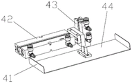
As shown in fig. 7, the pipe pushing mechanism 4 includes a pushing plate 44, a horizontal cylinder 42 and a vertical cylinder 43, a piston rod of the horizontal cylinder 42 is parallel to the first conveying belt 2, the vertical cylinder 43 is fixed on the piston rod of the horizontal cylinder 42, a piston rod of the vertical cylinder 43 is perpendicular to the first conveying belt 2, an upward flange 41 is arranged at the front end of the pushing plate 44, and the front end of the pushing plate 44 is obliquely fixed on the piston rod of the vertical cylinder 43 downward. The pipe pushing mechanism 4 can make the pushing plate 44 move horizontally in the front-back direction and vertically up and down, so as to push the straws at the discharging end of the first conveying belt 2 into the U-shaped groove block 61 of the slewing mechanism 6. The downward inclination of the front ends of the flanging 41 and the push plate 44 can help the straw to be pushed.
As shown in fig. 8, the secondary alignment mechanism 5 includes two secondary alignment plates 52 parallel to each other and two secondary alignment cylinders 51, the two secondary alignment plates 52 are perpendicular to the rotary plate 62 of the rotary mechanism 6, the two secondary alignment cylinders 51 are overlapped, and piston rods thereof are respectively fixed to the two secondary alignment plates 52 perpendicularly. The secondary aligning mechanism 5 can repeatedly move the two secondary aligning plates 52 toward each other, thereby aligning both ends of the straw in the U-shaped groove block 61.
As shown in fig. 9, the rotation mechanism 6 includes a rotation disc 62, a rotation shaft 65, a servo motor 63 and a belt pulley transmission mechanism 64, the rotation disc 62 is fixed on the rotation shaft 65, an output shaft of the servo motor 63 is connected with the rotation shaft 65 through the belt pulley transmission mechanism 64, four U-shaped groove blocks 61 are fixed on the rotation disc 62, the four U-shaped groove blocks 61 are uniformly arranged on the rotation disc 62 along the circumferential direction and are located on the same circle, and when the rotation disc 62 rotates, the U-shaped groove blocks 61 can pass between the two secondary alignment plates 52. The revolving mechanism 6 repeatedly rotates 1/4 circles, so that the four U-shaped groove blocks 61 repeatedly and sequentially stay between the two secondary alignment plates 52, and receive the straws pushed by the tube pushing mechanism 4 at the position, and the straws in the U-shaped groove blocks 61 rotate 1/4 circles with the revolving disc 62 to the next station after secondary alignment.
As shown in fig. 10, the grabbing mechanism 7 includes a sliding block 71, a sliding rail 75, a first air cylinder 72, a second air cylinder 76, two third air cylinders 74 and a suction pipe claw 73, the sliding rail 75 and the first air cylinder 72 are mounted and fixed on a baffle plate at one side of the second conveyor belt 8 and are parallel to the second conveyor belt 8, the sliding block 71 is fixed on a piston rod of the first air cylinder 72, the sliding block is located on the sliding rail 75 and is in sliding fit with the sliding rail, the second air cylinder 76 is fixed on the sliding block 71 and is perpendicular to the second conveyor belt 8, and the two third air cylinders 74 are overlapped and fixed on a piston rod of the second air cylinder 76 and control the opening and closing of the suction pipe claw 73. The first air cylinder 72 in the grabbing mechanism 7 makes the suction pipe claw 73 perform reciprocating horizontal motion, the second air cylinder 76 makes the suction pipe claw 73 perform vertical up-and-down motion, and the two third air cylinders 74 make the suction pipe claw 73 perform opening and closing motion, so that the suction pipe in the U-shaped groove block 61 below the grabbing mechanism 7 is grabbed onto the second conveying belt 8.
The pipe shifting mechanism 1 is used for shifting and conveying straws coming out of the cutting equipment to the first conveying belt 2, the primary alignment mechanism 3 is positioned on the first conveying belt 2 and drives the two primary alignment plates 32 to move through the extension and retraction of piston rods of the two primary alignment cylinders 31, so that the two ends of the straws which are arranged on the first conveying belt 2 and run are aligned; the pipe pushing mechanism 4 is positioned on the first conveying belt 2 and pushes the straws with two aligned ends to the rotating mechanism 6; the secondary alignment mechanism 5 aligns the two ends of the suction pipe on the rotary mechanism 6 again; the swing mechanism 6 receives the straws pushed by the tube pushing mechanism 4, and rotates the straws 90 degrees to the next station after the straws are aligned twice; the gripping mechanism 7 grips the straws on the rotating mechanism 6 onto the second conveyor belt 8. The pipe pushing mechanism 4 is arranged at the discharge end of the first conveying belt 2, the primary aligning mechanism 3 is arranged between the pipe pushing mechanism 4 and the pipe pushing mechanism 1, the swing mechanism 6 is arranged below the discharge end of the first conveying belt 2, the secondary aligning mechanism 5 is arranged on the pipe pushing mechanism 4 and is arranged above the swing mechanism 6, the grabbing mechanism 7 is arranged above the feed end of the second conveying belt 8, the discharge end of the second conveying belt 8 is arranged at the bottom of the buffer storage bin 10, the feed end of the third conveying belt 9 is arranged at the bottom of the buffer storage bin 10, the discharge end of the second conveying belt 8 is connected with the feed end of the third conveying belt 9 through a connecting plate 12, and the discharge end of the third conveying belt 9 is connected with the storage bin of the straw packaging machine. The buffer bin 10 is used for temporarily storing straws to ensure the feeding of the straw packing machine, and the width of the inner cavity of the buffer bin 10 (i.e. the distance between the baffles at the two sides of the buffer bin 10) is slightly larger than the length of the straws. The straw inlet at the bottom of the buffer bin outside the buffer bin 10 is provided with a pipe shifting wheel 11 controlled by a speed reducing motor, and the pipe shifting wheel 11 can enable straws on the second conveying belt 8 to smoothly enter the buffer bin 10. The second conveyor belt 8 and the third conveyor belt 9 are perpendicular to the first conveyor belt 2.
All the cylinders and the motors are connected with an air source and a control system. Straws coming out of the pipe cutting and arranging machine are conveyed to a first conveying belt 2 through a conveying belt of a pipe conveying mechanism 1, after the first conveying belt 2 is aligned with two ends for the first time through a primary aligning mechanism 3, the straws are conveyed to a pipe pushing mechanism 4 continuously, a push plate 44 of the pipe pushing mechanism 4 performs reciprocating back-and-forth movement and up-and-down movement under the action of a horizontal air cylinder 42 and a vertical air cylinder 43, so that the straws are bundled and pushed to one (the one staying between two secondary aligning plates 52) U-shaped groove block 61 on a rotary disc 62 of the rotary mechanism 6, after the straws are aligned with two ends again through a secondary aligning mechanism 5, the rotary disc 62 of the rotary mechanism 6 rotates 1/4 circles anticlockwise to the next station to realize the turning of two ends of the straws, and then a grabbing mechanism 7 performs reciprocating horizontal movement on a straw claw 73 under the action of a first air cylinder 72, a second air cylinder 76 and a third air cylinder 74, Vertical motion and opening and shutting motion to snatch the beam forming straw after the secondary aligns to second conveyer belt 8 on, carry to buffer memory storehouse 10 in through the straw import of buffer memory storehouse 10 bottom rear end through second conveyer belt 8 in to pile up in buffer memory storehouse 10, the straw is pushed to the third conveyer belt 9 simultaneously, is carried to the storage silo of straw packagine machine in through the straw export of buffer memory storehouse 10 bottom front end by third conveyer belt 9.
Claims (8)
1. Straw apparatus for producing's connection transfer chain, its characterized in that: the automatic pipe pushing and conveying device comprises a pipe pushing mechanism (1), a first conveying belt (2), a primary aligning mechanism (3), a pipe pushing mechanism (4), a secondary aligning mechanism (5), a rotating mechanism (6), a grabbing mechanism (7), a second conveying belt (8), a buffer bin (10) and a third conveying belt (9), wherein straws coming out of a cutting device are pushed to the first conveying belt by the pipe pushing mechanism, and the primary aligning mechanism is positioned on the first conveying belt and aligns two ends of straws arranged on the first conveying belt; the pipe pushing mechanism is positioned on the first conveyor belt and pushes the suction pipes with two aligned ends to the rotating mechanism; the secondary alignment mechanism aligns the two ends of the suction pipe on the rotary mechanism again; the swing mechanism receives the straws pushed by the tube pushing mechanism, and rotates the straws by 90 degrees to the next station after the straws are aligned twice; the grabbing mechanism grabs the suction pipe on the rotating mechanism onto the second conveying belt; the pipe pushing mechanism is located at the discharge end of the first conveying belt, the primary aligning mechanism is located between the pipe pushing mechanism and the pipe pushing mechanism, the rotating mechanism is located below the discharge end of the first conveying belt, the secondary aligning mechanism is mounted on the pipe pushing mechanism and located above the rotating mechanism, the grabbing mechanism is located above the feed end of the second conveying belt, the discharge end of the second conveying belt is located at the bottom of the buffer storage bin, the feed end of the third conveying belt is located at the bottom of the buffer storage bin, the discharge end of the second conveying belt is connected with the feed end of the third conveying belt through a connecting plate (12) in a front-back mode, the discharge end of the third conveying belt is connected with a storage bin of the straw packaging machine, and the second conveying belt and the third conveying belt are perpendicular to the first conveying belt.
2. The connecting conveyor line of the straw production apparatus according to claim 1, wherein: the pipe shifting mechanism (1) comprises a motor (11), a transmission belt (13), a driving belt pulley (12), a driven belt pulley (14) and a conveying belt (15), wherein the driving belt pulley is fixed on an output shaft of the motor and is connected with the driven belt pulley through the transmission belt, and the driven belt pulley drives the conveying belt to transmit.
3. The connecting conveyor line of the straw production apparatus according to claim 1, wherein: the primary alignment mechanism (3) comprises two primary alignment plates 32 and two primary alignment cylinders 31 which are parallel to each other, the two primary alignment plates are respectively and vertically positioned at two sides of the first conveying belt (2), the two primary alignment cylinders are overlapped, and piston rods of the primary alignment plates are respectively and vertically fixed with the two primary alignment plates.
4. The connecting conveyor line of the straw production apparatus according to claim 1, wherein: the pipe pushing mechanism (4) comprises a pushing plate (44), a horizontal cylinder (42) and a vertical cylinder (43), a piston rod of the horizontal cylinder is parallel to the first conveying belt (2), the vertical cylinder is fixed on the piston rod of the horizontal cylinder, the piston rod of the vertical cylinder is perpendicular to the first conveying belt, an upward flanging (41) is arranged at the front end of the pushing plate, and the front end of the pushing plate is obliquely fixed on the piston rod of the vertical cylinder downwards.
5. The connecting conveyor line of the straw production apparatus according to claim 1, wherein: the secondary alignment mechanism (5) comprises two secondary alignment plates (52) which are parallel to each other and two secondary alignment cylinders (51), the two secondary alignment plates are perpendicular to a rotary disc (62) of the rotary mechanism, the two secondary alignment cylinders are overlapped, and piston rods of the two secondary alignment cylinders are respectively and vertically fixed with the two secondary alignment plates.
6. The connecting conveyor line of the straw production apparatus according to claim 1, wherein: rotation mechanism (6) are including gyration dish (62), revolving axle (65), servo motor (63) and belt pulley drive mechanism (64), and the gyration dish is fixed on the revolving axle, and servo motor's output shaft passes through belt pulley drive mechanism and is connected with the revolving axle, is fixed with four U-shaped groove pieces (61) on the gyration dish, and four U-shaped groove pieces evenly arrange and lie in same circle along circumference on the gyration dish, and when the gyration dish was rotatory, the U-shaped groove piece can be followed two secondaries and aimed at the process between the board.
7. The connecting conveyor line of the straw production apparatus according to claim 1, wherein: the grabbing mechanism (7) comprises a sliding block (71), a sliding rail (75), a first air cylinder (72), a second air cylinder (76), two third air cylinders (74) and a suction pipe claw (73), the sliding rail and the first air cylinder are fixedly arranged on a baffle on one side of the second conveying belt (8) and are parallel to the second conveying belt, the sliding block is fixed on a piston rod of the first air cylinder, the sliding block is located on the sliding rail and is in sliding fit with the sliding rail, the second air cylinder is fixed on the sliding block and is perpendicular to the second conveying belt, and the two third air cylinders are fixedly overlapped on a piston rod of the second air cylinder and control the suction pipe claw to open and close.
8. The connecting conveyor line of the straw production apparatus according to claim 1, wherein: a straw shifting wheel (11) controlled by a speed reducing motor is arranged at the straw inlet at the bottom of the buffer bin outside the buffer bin (10).
Priority Applications (1)
| Application Number | Priority Date | Filing Date | Title |
|---|---|---|---|
| CN202110927013.3A CN113619856A (en) | 2021-08-12 | 2021-08-12 | Connecting conveying line of straw production device |
Applications Claiming Priority (1)
| Application Number | Priority Date | Filing Date | Title |
|---|---|---|---|
| CN202110927013.3A CN113619856A (en) | 2021-08-12 | 2021-08-12 | Connecting conveying line of straw production device |
Publications (1)
| Publication Number | Publication Date |
|---|---|
| CN113619856A true CN113619856A (en) | 2021-11-09 |
Family
ID=78385027
Family Applications (1)
| Application Number | Title | Priority Date | Filing Date |
|---|---|---|---|
| CN202110927013.3A Pending CN113619856A (en) | 2021-08-12 | 2021-08-12 | Connecting conveying line of straw production device |
Country Status (1)
| Country | Link |
|---|---|
| CN (1) | CN113619856A (en) |
Citations (11)
| Publication number | Priority date | Publication date | Assignee | Title |
|---|---|---|---|---|
| TW506411U (en) * | 2001-07-27 | 2002-10-11 | Chiou-Shiung Ji | Box for collecting plastic straws |
| CN202321615U (en) * | 2011-09-28 | 2012-07-11 | 昆明欧迈科技有限公司 | Rod 90-degree-turning conveyor |
| CN202657657U (en) * | 2012-04-27 | 2013-01-09 | 砀山县金利塑业有限公司 | Suction tube neatening device |
| KR20170114377A (en) * | 2016-04-04 | 2017-10-16 | 주식회사 선진엠앤에스 | Part exchange type straw packing machine |
| CN107651240A (en) * | 2016-07-26 | 2018-02-02 | 柳韩Nci株式会社 | Package bag automatic packing machine |
| CN108274718A (en) * | 2018-03-30 | 2018-07-13 | 漳州杰安塑料有限公司 | A kind of automatic high-efficiency production equipment of suction pipe |
| CN207860610U (en) * | 2018-01-03 | 2018-09-14 | 深圳市鑫宏扬包装制品有限公司 | The rotating disk mechanism of high frequency disk machine |
| CN109896487A (en) * | 2019-03-28 | 2019-06-18 | 江苏新美星包装机械股份有限公司 | Suction pipe is in charge of transfer |
| CN111747058A (en) * | 2020-07-22 | 2020-10-09 | 安徽金利塑业股份有限公司 | Material receiving system after straw material breaking |
| CN111776317A (en) * | 2020-07-30 | 2020-10-16 | 杭州隆歌机械有限公司 | Multi-package straw packaging machine |
| CN213008956U (en) * | 2020-07-13 | 2021-04-20 | 苏州知常智能科技有限公司 | Stationery turntable type conveying device |
-
2021
- 2021-08-12 CN CN202110927013.3A patent/CN113619856A/en active Pending
Patent Citations (11)
| Publication number | Priority date | Publication date | Assignee | Title |
|---|---|---|---|---|
| TW506411U (en) * | 2001-07-27 | 2002-10-11 | Chiou-Shiung Ji | Box for collecting plastic straws |
| CN202321615U (en) * | 2011-09-28 | 2012-07-11 | 昆明欧迈科技有限公司 | Rod 90-degree-turning conveyor |
| CN202657657U (en) * | 2012-04-27 | 2013-01-09 | 砀山县金利塑业有限公司 | Suction tube neatening device |
| KR20170114377A (en) * | 2016-04-04 | 2017-10-16 | 주식회사 선진엠앤에스 | Part exchange type straw packing machine |
| CN107651240A (en) * | 2016-07-26 | 2018-02-02 | 柳韩Nci株式会社 | Package bag automatic packing machine |
| CN207860610U (en) * | 2018-01-03 | 2018-09-14 | 深圳市鑫宏扬包装制品有限公司 | The rotating disk mechanism of high frequency disk machine |
| CN108274718A (en) * | 2018-03-30 | 2018-07-13 | 漳州杰安塑料有限公司 | A kind of automatic high-efficiency production equipment of suction pipe |
| CN109896487A (en) * | 2019-03-28 | 2019-06-18 | 江苏新美星包装机械股份有限公司 | Suction pipe is in charge of transfer |
| CN213008956U (en) * | 2020-07-13 | 2021-04-20 | 苏州知常智能科技有限公司 | Stationery turntable type conveying device |
| CN111747058A (en) * | 2020-07-22 | 2020-10-09 | 安徽金利塑业股份有限公司 | Material receiving system after straw material breaking |
| CN111776317A (en) * | 2020-07-30 | 2020-10-16 | 杭州隆歌机械有限公司 | Multi-package straw packaging machine |
Similar Documents
| Publication | Publication Date | Title |
|---|---|---|
| CN104724475A (en) | Glass pipe conveying plant | |
| CN110254866B (en) | Full-automatic pipe joint counting and packaging equipment | |
| CN212149538U (en) | Automatic carton packaging system | |
| CN114313926A (en) | Material discharging vibration disc equipment convenient for efficient grabbing of manipulator | |
| CN113619856A (en) | Connecting conveying line of straw production device | |
| CN210340294U (en) | Empty bottle pneumatic conveying equipment for bottled production line | |
| CN210192034U (en) | Robot-controlled pipe joint labeling and packaging equipment | |
| CN112744415A (en) | High-speed full-automatic self-standing bag packing machine | |
| CN215286862U (en) | Small-size packaging container finishing device | |
| CN1810488B (en) | Rotary type full-automatic plastic bottle blowing machine | |
| US5018336A (en) | System and process for producing or treating cylindrical articles and apparatus employable therein | |
| CN104816851A (en) | Lane separation device for gift box milk automated production | |
| CN206187440U (en) | Material packing machine | |
| CN210259133U (en) | Full-automatic pipe joint counting and packaging equipment | |
| CN212400010U (en) | A prilling granulator for producing anticorrosive heat preservation protective layer special-purpose material of PP | |
| CN210824276U (en) | Flow dividing device for pneumatically adjusting conveying direction | |
| CN112319922A (en) | Full-automatic nylon ribbon cuts packaging all-in-one | |
| CN208377246U (en) | A kind of honeycomb briquette automatic packaging production line | |
| CN220412192U (en) | A batching transfer device for insulation block production | |
| CN209553622U (en) | A kind of driving means that the copy paper by heap poststack pushes | |
| CN221024317U (en) | Edible butter finished product batch boxing equipment | |
| CN216836188U (en) | Automatic feed mechanism who divides material | |
| CN216301619U (en) | Automatic aggregate device | |
| CN212474245U (en) | Automatic bagging and feeding device for bagged granular materials | |
| CN219756715U (en) | Full-automatic filling unit for refrigerant |
Legal Events
| Date | Code | Title | Description |
|---|---|---|---|
| PB01 | Publication | ||
| PB01 | Publication | ||
| SE01 | Entry into force of request for substantive examination | ||
| SE01 | Entry into force of request for substantive examination |