CN113443430A - Feeding device for plate processing - Google Patents
Feeding device for plate processing Download PDFInfo
- Publication number
- CN113443430A CN113443430A CN202111000417.4A CN202111000417A CN113443430A CN 113443430 A CN113443430 A CN 113443430A CN 202111000417 A CN202111000417 A CN 202111000417A CN 113443430 A CN113443430 A CN 113443430A
- Authority
- CN
- China
- Prior art keywords
- assembly
- clamping
- plate
- frame
- driving
- Prior art date
- Legal status (The legal status is an assumption and is not a legal conclusion. Google has not performed a legal analysis and makes no representation as to the accuracy of the status listed.)
- Granted
Links
Images


Classifications
-
- B—PERFORMING OPERATIONS; TRANSPORTING
- B65—CONVEYING; PACKING; STORING; HANDLING THIN OR FILAMENTARY MATERIAL
- B65G—TRANSPORT OR STORAGE DEVICES, e.g. CONVEYORS FOR LOADING OR TIPPING, SHOP CONVEYOR SYSTEMS OR PNEUMATIC TUBE CONVEYORS
- B65G47/00—Article or material-handling devices associated with conveyors; Methods employing such devices
- B65G47/74—Feeding, transfer, or discharging devices of particular kinds or types
- B65G47/90—Devices for picking-up and depositing articles or materials
- B65G47/902—Devices for picking-up and depositing articles or materials provided with drive systems incorporating rotary and rectilinear movements
-
- B—PERFORMING OPERATIONS; TRANSPORTING
- B65—CONVEYING; PACKING; STORING; HANDLING THIN OR FILAMENTARY MATERIAL
- B65G—TRANSPORT OR STORAGE DEVICES, e.g. CONVEYORS FOR LOADING OR TIPPING, SHOP CONVEYOR SYSTEMS OR PNEUMATIC TUBE CONVEYORS
- B65G47/00—Article or material-handling devices associated with conveyors; Methods employing such devices
- B65G47/74—Feeding, transfer, or discharging devices of particular kinds or types
- B65G47/90—Devices for picking-up and depositing articles or materials
- B65G47/91—Devices for picking-up and depositing articles or materials incorporating pneumatic, e.g. suction, grippers
- B65G47/914—Devices for picking-up and depositing articles or materials incorporating pneumatic, e.g. suction, grippers provided with drive systems incorporating rotary and rectilinear movements
-
- B—PERFORMING OPERATIONS; TRANSPORTING
- B65—CONVEYING; PACKING; STORING; HANDLING THIN OR FILAMENTARY MATERIAL
- B65G—TRANSPORT OR STORAGE DEVICES, e.g. CONVEYORS FOR LOADING OR TIPPING, SHOP CONVEYOR SYSTEMS OR PNEUMATIC TUBE CONVEYORS
- B65G2201/00—Indexing codes relating to handling devices, e.g. conveyors, characterised by the type of product or load being conveyed or handled
- B65G2201/02—Articles
- B65G2201/0214—Articles of special size, shape or weigh
- B65G2201/022—Flat
Abstract
The invention discloses a feeding device for plate processing, which comprises: a support frame; the clamping assembly is positioned on one side of the supporting frame and used for clamping a plate; the adjusting assembly is connected with the clamping assembly and is used for adjusting the height and the rotating angle of the clamping assembly; the moving assembly is connected with the adjusting assembly and is used for driving the clamping assembly to move in position; the clamping assembly includes: the device comprises a clamping plate, a telescopic assembly, a sucker, a lifting assembly and a connecting assembly; the adjusting assembly is convenient for adjusting the vertical direction position and the horizontal direction angle of the clamping assembly, so that the clamping assembly is convenient for clamping the plate and adjusting the horizontal direction angle of the plate in the carrying process; the clamping plate and the sucking disc in the clamping assembly are convenient to clamp and adsorb the plate, so that the plate can be effectively prevented from falling off in the feeding process; coupling assembling can realize carrying out the clamp of level and vertical direction to panel, effectively improves the stability of panel at the material loading in-process.
Description
Technical Field
The invention relates to the technical field of plate processing, in particular to a feeding device for plate processing.
Background
The plate needs to be fed by the conveying device in the processing process, so that the plate can be orderly moved to the processing device and then processed.
The feeding device for processing the existing plates is used for clamping and moving the plates, the operation is complicated, the plates cannot be effectively kept stable in the moving process, the plates need to be manually adjusted and clamped, and the plate processing efficiency is reduced.
Disclosure of Invention
The invention aims to provide a feeding device for plate processing, which aims to solve the problems in the background technology.
In order to achieve the purpose, the invention provides the following technical scheme:
a feeding device for plate processing comprises:
a support frame;
the clamping assembly is positioned on one side of the supporting frame and used for clamping the plate and driving the plate to move;
the adjusting assembly is connected with the clamping assembly and is used for adjusting the height and the rotating angle of the clamping assembly;
the moving assembly is connected with the adjusting assembly and is used for driving the clamping assembly to move in position;
the clamping assembly includes:
the clamping plates are positioned on one side of the supporting frame, at least two clamping plates are arranged, and the clamping plates are used for being connected with the plates and clamping and supporting the plates;
the telescopic assembly is positioned on one side of the adjusting assembly and is used for adjusting the distance between the two clamping plates so that the clamping plates clamp the plate;
the sucking disc is positioned on the telescopic assembly and used for sucking the plate and limiting the position of the plate;
the lifting assembly is connected with the clamping plate and used for driving the clamping plate to move in the vertical direction;
and the connecting assembly is positioned on the telescopic assembly and used for connecting the telescopic assembly and the lifting assembly so as to enable the clamping plate to move in the vertical direction in the horizontal moving process.
As another preferable aspect of the embodiment of the present invention, the adjusting assembly includes:
the telescopic piece is positioned on one side of the supporting frame and used for driving the clamping assembly to move in the vertical direction;
the fixing frame is connected with the telescopic piece and is used for supporting the telescopic piece and the clamping assembly;
the rotating bearing is positioned between the telescopic piece and the fixed frame and is used for enabling the telescopic piece to rotate on the fixed frame;
and the rotating assembly is positioned on the inner side of the fixed frame, is connected with the telescopic piece and is used for driving the telescopic piece and the clamping assembly to rotate.
As another preferable aspect of the embodiment of the present invention, the rotating assembly includes:
the fixing column is positioned at one end of the telescopic piece and is fixedly connected with the telescopic piece;
the gear ring is positioned on the outer side of the fixed column, is fixedly connected with the fixed column and is used for driving the fixed column to rotate;
the driving piece is positioned on the inner side of the fixed frame and is fixedly arranged on the inner side of the fixed frame;
and the rotating rod is positioned at the output end of the driving piece, is connected with the gear ring and is used for rotationally driving the gear ring to rotate.
As another preferable aspect of the embodiment of the present invention, the moving assembly includes:
the guide rail is positioned on one side of the support frame, is fixedly connected with the support frame and is used for limiting the moving track of the clamping assembly;
the first driving motor is positioned on the inner side of the guide rail and is positioned at one end of the inner side of the guide rail;
the first threaded rod is positioned at the output end of the first driving motor and used for rotating and adjusting the clamping assembly to move;
and the moving block is positioned on the inner side of the guide rail, is connected with the adjusting component and is used for driving the adjusting component and the clamping component to move.
As another preferable aspect of the embodiment of the present invention, the telescopic assembly includes:
the supporting frame is positioned at one end of the adjusting assembly and used for supporting the clamping plate and the sucker;
the moving frame is positioned on the inner side of the supporting frame and used for moving along the supporting frame;
the second driving motor is positioned on the inner side of the supporting frame and is fixedly connected with the supporting frame;
and the second threaded rod is positioned at the output end of the second driving motor, is connected with the movable frame and is used for driving the movable frame to move along the supporting frame.
As another preferable aspect of the embodiment of the present invention, the connection assembly includes:
the connecting plate is positioned at one end of the second threaded rod and positioned on the inner side of the movable frame;
the rack is positioned on the connecting plate and is fixedly connected with the connecting plate;
the sliding chute is positioned on the inner side of the moving frame, is connected with the connecting plate and is used for limiting the moving track of the moving frame;
and the slotted hole is positioned on the movable frame and used for supporting the rack.
As another preferable aspect of the embodiment of the present invention, the lifting assembly includes:
the clamping frame is positioned at one end of the telescopic assembly and used for supporting the clamping plate;
the rotating rod is positioned on the inner side of the clamping frame and is rotationally connected with the clamping frame;
the gear is positioned at one end of the rotating rod, is connected with the connecting assembly and is used for rotating when the telescopic assembly works;
the sliding block is positioned on the outer side of the rotating rod, is connected with the clamping plate and is used for driving the clamping plate to move in the vertical direction;
and the non-slip pad is positioned at one end of the clamping plate and used for slowing down the impact of the clamping plate on the plate.
As another preferable aspect of the embodiment of the present invention, the feeding device for processing a plate further includes: and the pressing assembly is connected with the sucker and used for adjusting the position of the sucker in the vertical direction and increasing the adsorption force of the sucker on the plate.
In the invention, the support frame conveniently supports the clamping assembly, the adjusting assembly and the moving assembly, and the moving assembly conveniently drives the clamping assembly and the plate to move, so that the plate is conveniently carried; the adjusting assembly is convenient for adjusting the vertical direction position and the horizontal direction angle of the clamping assembly, the clamping assembly is convenient for clamping the plate, the horizontal direction angle of the plate is adjusted in the carrying process, and the plate feeding operation is convenient; the clamping plate and the sucking disc in the clamping assembly are convenient to clamp and adsorb the plate, so that the plate can be effectively prevented from falling off in the feeding process; the telescopic assembly and the lifting assembly are connected through the connecting assembly, so that the plate can be clamped horizontally and vertically, and the stability of the plate in the feeding process is effectively improved.
Drawings
Fig. 1 is a schematic structural diagram of an embodiment of the present invention.
Fig. 2 is a schematic structural diagram of a clamping assembly in an embodiment of the invention.
Fig. 3 is a schematic structural diagram of a connecting assembly according to an embodiment of the present invention.
Fig. 4 is a schematic structural diagram of a lifting assembly in an embodiment of the invention.
Fig. 5 is a schematic structural diagram of a moving frame according to an embodiment of the present invention.
In the figure: 1-supporting frame, 2-clamping assembly, 3-adjusting assembly, 31-telescopic member, 32-fixed frame, 33-rotating bearing, 34-rotating assembly, 341-fixed column, 342-gear ring, 343-driving member, 344-rotating rod, 4-moving assembly, 41-guide rail, 42-first driving motor, 43-first threaded rod, 44-moving block, 5-telescopic assembly, 51-supporting frame, 52-moving frame, 53-second driving motor, 54-second threaded rod, 6-suction cup, 7-lifting assembly, 71-clamping frame, 72-rotating rod, 73-gear, 74-sliding block, 75-anti-sliding pad, 8-connecting assembly, 81-connecting plate, 82-rack, 82-sliding block, and the like, 83-sliding groove, 84-slotted hole, 9-pressing component and 10-clamping plate.
Detailed Description
The technical solutions in the embodiments of the present invention will be clearly and completely described below with reference to the drawings in the embodiments of the present invention, and it is obvious that the described embodiments are only a part of the embodiments of the present invention, and not all of the embodiments. All other embodiments, which can be derived by a person skilled in the art from the embodiments given herein without making any creative effort, shall fall within the protection scope of the present invention.
Referring to fig. 1 to 5, in an embodiment of the present invention, a feeding device for processing a sheet material includes:
a support frame 1;
the clamping assembly 2 is positioned on one side of the support frame 1 and used for clamping the plate and driving the plate to move;
the adjusting assembly 3 is connected with the clamping assembly 2 and is used for adjusting the height and the rotating angle of the clamping assembly 2;
the moving assembly 4 is connected with the adjusting assembly 3 and is used for driving the clamping assembly 2 to move in position;
the clamping assembly 2 comprises:
the clamping plates 10 are positioned on one side of the support frame 1, at least two clamping plates are arranged, and are used for being connected with the plates and clamping and supporting the plates;
the telescopic assembly 5 is positioned on one side of the adjusting assembly 3 and used for adjusting the distance between the two clamping plates so that the clamping plate 10 clamps the plate;
the sucking disc 6 is positioned on the telescopic component 5 and used for sucking the plate and limiting the position of the plate;
the lifting assembly 7 is connected with the clamping plate 10 and is used for driving the clamping plate 10 to move in the vertical direction;
and the connecting assembly 8 is positioned on the telescopic assembly 5 and used for connecting the telescopic assembly 5 and the lifting assembly 7, so that the clamping plate 10 can move in the vertical direction in the horizontal moving process.
In the embodiment, the support frame 1 is fixedly connected with the moving assembly 4, and the moving assembly 4 is convenient for driving the clamping assembly 2 and the plate to move, so that the plate can be conveniently conveyed; the adjusting assembly 3 is convenient for adjusting the vertical direction position and the horizontal direction angle of the clamping assembly 2, the clamping assembly 2 is convenient for clamping the plate, the horizontal direction angle of the plate is adjusted in the carrying process, and the plate feeding operation is convenient; the clamping plate 10 and the sucking disc 6 in the clamping assembly 2 are convenient for clamping and adsorbing the plate, and the plate can be effectively prevented from falling off in the feeding process; the telescopic assembly 5 and the lifting assembly 7 are connected through the connecting assembly 8, so that the plates can be clamped in the horizontal and vertical directions, and the stability of the plates in the feeding process is effectively improved; the telescopic assembly 5 can effectively control the distance between the two clamping plates 10, so that the plates can be conveniently clamped in the horizontal direction, the lifting assembly 7 can effectively support the plates and clamp the plates in the vertical direction, and the stability of the plates on the clamping assembly 2 is effectively improved; the sucking disc 6 is equipped with a plurality ofly, and the shape that sucking disc 6 is constituteed is circular, conveniently adsorbs panel, makes things convenient for clamping component 2 to carry out the centre gripping to panel.
In an embodiment of the present invention, referring to fig. 1, the adjusting assembly 3 includes:
the telescopic piece 31 is positioned on one side of the support frame 1 and used for driving the clamping assembly 2 to move in the vertical direction;
a fixed frame 32 connected with the telescopic member 31 and used for supporting the telescopic member 31 and the clamping assembly 2;
a rotation bearing 33, which is located between the telescopic member 31 and the fixed frame 32, for allowing the telescopic member 31 to rotate on the fixed frame 32;
and a rotating assembly 34 located inside the fixed frame 32 and connected with the telescopic member 31 for driving the telescopic member 31 and the clamping assembly 2 to rotate.
In this embodiment, extensible member 31 is flexible motor, and flexible motor output is connected with clamping component 2, and flexible motor is kept away from output one end and is connected with fixed frame 32, installs rolling bearing 33 between flexible motor and the fixed frame 32, and rolling bearing 33 can make things convenient for flexible motor to rotate on fixed frame 32, rotating component 34 is located fixed frame 32 inboard, makes things convenient for the flexible motor of drive to rotate, and further realization is to clamping component 2's rotation, and the convenience is adjusted the horizontal angle of panel, makes things convenient for panel to carry out the material loading, avoids follow-up artifical manual regulation panel, facilitates the use.
In one embodiment of the present invention, referring to fig. 1, the rotating assembly 34 includes:
a fixing column 341 located at one end of the telescopic member 31 and fixedly connected with the telescopic member 31;
the gear ring 342 is located on the outer side of the fixed column 341, is fixedly connected with the fixed column 341, and is used for driving the fixed column 341 to rotate;
a driving member 343 which is located inside the fixed frame 32 and is fixedly mounted inside the fixed frame 32;
and a rotating rod 344, which is located at the output end of the driving member 343 and connected to the gear ring 342, and is used for rotationally driving the gear ring 342 to rotate.
In this embodiment, the shape of fixed column 341 is cylindric, fixed column 341 and flexible motor fixed connection, and fixed column 341 outside fixed mounting has ring gear 342, driving piece 343 is the rotating electrical machines in this embodiment, and rotating electrical machines fixed mounting is inboard at fixed frame 32, and rotating electrical machines installs rotary rod 344 in the output, and rotary rod 344 is the worm in this embodiment, worm and ring gear 342 mesh are connected, control the worm as rotating electrical machines and rotate, make things convenient for drive ring gear 342 to rotate, and further realization flexible motor and clamping component 2's rotation makes things convenient for clamping component 2 to carry out the centre gripping to panel, and conveniently adjusts the angle of panel horizontal direction, facilitates the use.
In an embodiment of the present invention, referring to fig. 1, the moving assembly 4 includes:
the guide rail 41 is positioned on one side of the support frame 1, is fixedly connected with the support frame 1 and is used for limiting the moving track of the clamping assembly 2;
a first driving motor 42 located inside the guide rail 41 and located at one end inside the guide rail 41;
a first threaded rod 43, which is positioned at the output end of the first driving motor 42 and is used for rotationally adjusting the clamping component 2 to move;
and the moving block 44 is positioned on the inner side of the guide rail 41, is connected with the adjusting component 3, and is used for driving the adjusting component 3 and the clamping component 2 to move.
In this embodiment, the guide rail 41 is fixedly mounted on the support frame 1, the cross-sectional shape of the inner side of the guide rail 41 is convex, the inner side of the guide rail 41 is connected with the moving block 44 in a concave-convex manner, the guide rail 41 is convenient for supporting the moving block 44, and the moving block 44 is convenient to move along the guide rail 41, the moving block 44 is fixedly connected with the fixed frame 32 to conveniently drive the adjusting component 3 and the clamping component 2 to move, the first driving motor 42 is fixedly arranged at one end of the inner side of the guide rail 41, the output end of the first driving motor 42 is fixedly connected with the first threaded rod 43, one end of the first threaded rod 43 far away from the first driving motor 42 is rotatably connected with the inner side of the guide rail 41, the middle part of the moving block 44 is provided with a screw hole, the inner side of the screw hole is connected with the first threaded rod 43 through threads, when the first driving motor 42 controls the first threaded rod 43 to rotate, the moving block 44 conveniently moves inside the guide rail 41, and further movement of the plate is achieved.
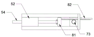
In one embodiment of the present invention, referring to fig. 1 and 2, the telescopic assembly 5 includes:
the supporting frame 51 is positioned at one end of the adjusting assembly 3 and is used for supporting the clamping plate 10 and the suction cup 6;
a moving frame 52 located inside the supporting frame 51 and moving along the supporting frame 51;
the second driving motor 53 is positioned on the inner side of the supporting frame 51 and is fixedly connected with the supporting frame 51;
and a second threaded rod 54, which is located at the output end of the second driving motor 53 and connected to the moving frame 52, and is used for driving the moving frame 52 to move along the supporting frame 51.
In this embodiment, a second driving motor 53 is installed in the middle of the inner side of the supporting frame 51, the second driving motor 53 is a double-shaft motor in this embodiment, a second threaded rod 54 is installed at both output ends of the double-shaft motor, the second threaded rod 54 is fixedly connected with the output end of the double-shaft motor, the movable frame 52 is in a shape of a square, a screw hole is arranged in the middle of one end of the movable frame 52, the inner side of the screw hole is in threaded connection with the outer side of the second threaded rod 54, when the second threaded rod 54 rotates, the movable frame 52 is conveniently driven to move along the supporting frame 51, the movable frame 52 is in concave-convex connection with the supporting frame 51, the supporting frame 51 is convenient for supporting the movable frame 52, one end of the movable frame 52 far away from the supporting frame 51 is provided with the clamping plate 10, through the rotation of the double-shaft motor, the distance between the two clamping plates 10 is convenient to adjust, the horizontal direction of the plate is convenient to clamp, and the use is convenient.
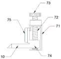
In one embodiment of the present invention, referring to fig. 1 and 4, the lifting assembly 7 includes:
a clamping frame 71 located at one end of the telescopic assembly 5 for supporting the clamping plate 10;
a rotating lever 72 positioned inside the clamping frame 71 and rotatably connected to the clamping frame 71;
a gear 73, which is located at one end of the rotating rod 72, is connected with the connecting assembly 8, and is used for rotating when the telescopic assembly 5 works;
the sliding block 74 is positioned outside the rotating rod 72, connected with the clamping plate 10 and used for driving the clamping plate 10 to move in the vertical direction;
and the non-slip pad 75 is positioned at one end of the clamping plate 10 and is used for relieving the impact of the clamping plate 10 on the plate.
In this embodiment, press from both sides tight frame 71 and remove frame 52 and keep away from carriage 51 one end fixed connection, press from both sides tight frame 71 inboard and install dwang 72, dwang 72 is the third threaded rod in this embodiment, and the third threaded rod is kept away from tight frame 71 one end and is installed gear 73, the third threaded rod is close to tight frame 71 one end of clamp and is rotated with pressing from both sides tight frame 71 and be connected, slider 74 is located and presss from both sides tight frame 71 inboard, and slider 74 and the unsmooth connection of tight frame 71 of clamp, slider 74 can remove along pressing from both sides tight frame 71, and slider 74 side-mounting has clamping plate 10 and slipmat 75, conveniently presss from both sides tightly and support panel, facilitates the use, slider 74 middle part is equipped with the screw, the inboard and the third threaded rod threaded connection of screw, when the third threaded rod rotated, conveniently adjusts slider 74 in the inboard position of tight frame 71 of clamp, facilitates the use.
In an embodiment of the present invention, referring to fig. 1, 3 and 5, the connecting component 8 includes:
a connection plate 81 located at one end of the second threaded rod 54 and located inside the moving frame 52;
the rack 82 is positioned on the connecting plate 81 and is fixedly connected with the connecting plate 81;
a chute 83 located inside the moving frame 52 and connected to the connecting plate 81 for limiting the moving track of the moving frame 52;
and a slot 84 located on the moving frame 52 for supporting the rack 82.
In this embodiment, the sliding groove 83 is located inside the moving frame 52, the inside of the sliding groove 83 is in concave-convex connection with the connecting plate 81 to facilitate supporting and limiting the connecting plate 81, one side of the connecting plate 81 is rotatably connected with the second threaded rod 54, when the second threaded rod 54 rotates, the connecting plate 81 remains stationary, the moving frame 52 moves along the supporting frame 51, the other end of the connecting plate 81 is provided with a rack 82, the rack 82 passes through a slot 84 on the moving frame 52, the slot 84 facilitates supporting the rack 82, the rack 82 is connected with the gear 73 on the lifting assembly 7 in a meshing manner, the slot 84 can also limit the rack 82 to enable the rack 82 to be always meshed with the gear 73, when the moving frame 52 moves in the horizontal direction, the gear 73 can rotate through the rack 82 to facilitate adjusting the position of the clamping plate 10 in the vertical direction, when the plate is clamped in the horizontal direction, at the moment, the clamping plate 10 moves upwards to clamp the plate in the vertical direction, and the use is convenient.
In an embodiment of the present invention, referring to fig. 1 and 2, the feeding device for processing a plate further includes: compress tightly subassembly 9, with sucking disc 6 is connected for adjust the position of sucking disc 6 in vertical direction, and increase sucking disc 6 is to the adsorption affinity of panel, it is equipped with spacing frame, stopper and elastic component to compress tightly 9 inboards of subassembly, stopper fixed mounting is in carriage 51 one side, spacing frame and sucking disc 6 fixed connection, spacing frame and stopper unsmooth the connection, the elastic component is located between spacing frame and the stopper, and the elastic component is the spring in this embodiment, when pressing from both sides tight panel, can effectively improve the pressure of sucking disc 6 to panel through the spring, further improvement sucking disc 6's adsorption affinity facilitates the use.
In the invention, the moving assembly 4 drives the adjusting assembly 3 and the clamping assembly 2 to move, so that plates can be conveniently carried, the adjusting assembly 3 is convenient for adjusting the clamping assembly 2 to move in the vertical direction and adjust the angle in the horizontal direction, so that the plates can be conveniently clamped and supported, the clamped plates can be further adjusted in angle, so that the plates can be conveniently fed, the telescopic assembly 5 in the clamping assembly 2 is convenient for horizontally clamping the plates, the lifting assembly 7 can clamp the plates in the vertical direction, so that the stability of the plates in the feeding process can be effectively improved, the connecting assembly 8 can enable the clamping plate 10 to move in the vertical direction in the horizontal moving process, so that the plates can be rapidly clamped, the operation is convenient and rapid, and the working efficiency of plate feeding is effectively improved.
It will be evident to those skilled in the art that the invention is not limited to the details of the foregoing illustrative embodiments, and that the present invention may be embodied in other specific forms without departing from the spirit or essential attributes thereof. The present embodiments are therefore to be considered in all respects as illustrative and not restrictive, the scope of the invention being indicated by the appended claims rather than by the foregoing description, and all changes which come within the meaning and range of equivalency of the claims are therefore intended to be embraced therein. Any reference sign in a claim should not be construed as limiting the claim concerned.
Furthermore, it should be understood that although the present description refers to embodiments, not every embodiment may contain only a single embodiment, and such description is for clarity only, and those skilled in the art should integrate the description, and the embodiments may be combined as appropriate to form other embodiments understood by those skilled in the art.
Claims (8)
1. The utility model provides a loading attachment is used in panel processing which characterized in that, loading attachment includes for the panel processing:
a support frame;
the clamping assembly is positioned on one side of the supporting frame and used for clamping the plate and driving the plate to move;
the adjusting assembly is connected with the clamping assembly and is used for adjusting the height and the rotating angle of the clamping assembly;
the moving assembly is connected with the adjusting assembly and is used for driving the clamping assembly to move in position;
the clamping assembly includes:
the clamping plates are positioned on one side of the supporting frame, at least two clamping plates are arranged, and the clamping plates are used for being connected with the plates and clamping and supporting the plates;
the telescopic assembly is positioned on one side of the adjusting assembly and is used for adjusting the distance between the two clamping plates so that the clamping plates clamp the plate;
the sucking disc is positioned on the telescopic assembly and used for sucking the plate and limiting the position of the plate;
the lifting assembly is connected with the clamping plate and used for driving the clamping plate to move in the vertical direction;
and the connecting assembly is positioned on the telescopic assembly and used for connecting the telescopic assembly and the lifting assembly so as to enable the clamping plate to move in the vertical direction in the horizontal moving process.
2. The feeding device for processing the plate material as recited in claim 1, wherein the adjusting assembly comprises:
the telescopic piece is positioned on one side of the supporting frame and used for driving the clamping assembly to move in the vertical direction;
the fixing frame is connected with the telescopic piece and is used for supporting the telescopic piece and the clamping assembly;
the rotating bearing is positioned between the telescopic piece and the fixed frame and is used for enabling the telescopic piece to rotate on the fixed frame;
and the rotating assembly is positioned on the inner side of the fixed frame, is connected with the telescopic piece and is used for driving the telescopic piece and the clamping assembly to rotate.
3. A feeding device for processing sheet material as claimed in claim 2, wherein said rotating assembly comprises:
the fixing column is positioned at one end of the telescopic piece and is fixedly connected with the telescopic piece;
the gear ring is positioned on the outer side of the fixed column, is fixedly connected with the fixed column and is used for driving the fixed column to rotate;
the driving piece is positioned on the inner side of the fixed frame and is fixedly arranged on the inner side of the fixed frame;
and the rotating rod is positioned at the output end of the driving piece, is connected with the gear ring and is used for rotationally driving the gear ring to rotate.
4. A loading apparatus for processing a plate material as recited in claim 1, wherein said moving means comprises:
the guide rail is positioned on one side of the support frame, is fixedly connected with the support frame and is used for limiting the moving track of the clamping assembly;
the first driving motor is positioned on the inner side of the guide rail and is positioned at one end of the inner side of the guide rail;
the first threaded rod is positioned at the output end of the first driving motor and used for rotating and adjusting the clamping assembly to move;
and the moving block is positioned on the inner side of the guide rail, is connected with the adjusting component and is used for driving the adjusting component and the clamping component to move.
5. The feeding device for processing the plate material as claimed in claim 1, wherein the telescopic assembly comprises:
the supporting frame is positioned at one end of the adjusting assembly and used for supporting the clamping plate and the sucker;
the moving frame is positioned on the inner side of the supporting frame and used for moving along the supporting frame;
the second driving motor is positioned on the inner side of the supporting frame and is fixedly connected with the supporting frame;
and the second threaded rod is positioned at the output end of the second driving motor, is connected with the movable frame and is used for driving the movable frame to move along the supporting frame.
6. A feeding device for processing plates, according to claim 5, wherein said connection assembly comprises:
the connecting plate is positioned at one end of the second threaded rod and positioned on the inner side of the movable frame;
the rack is positioned on the connecting plate and is fixedly connected with the connecting plate;
the sliding chute is positioned on the inner side of the moving frame, is connected with the connecting plate and is used for limiting the moving track of the moving frame;
and the slotted hole is positioned on the movable frame and used for supporting the rack.
7. The feeding device for processing the plate material as claimed in claim 1, wherein the lifting assembly comprises:
the clamping frame is positioned at one end of the telescopic assembly and used for supporting the clamping plate;
the rotating rod is positioned on the inner side of the clamping frame and is rotationally connected with the clamping frame;
the gear is positioned at one end of the rotating rod, is connected with the connecting assembly and is used for rotating when the telescopic assembly works;
the sliding block is positioned on the outer side of the rotating rod, is connected with the clamping plate and is used for driving the clamping plate to move in the vertical direction;
and the non-slip pad is positioned at one end of the clamping plate and used for slowing down the impact of the clamping plate on the plate.
8. The feeding device for processing a plate material as recited in claim 1, further comprising: and the pressing assembly is connected with the sucker and used for adjusting the position of the sucker in the vertical direction and increasing the adsorption force of the sucker on the plate.
Priority Applications (1)
| Application Number | Priority Date | Filing Date | Title |
|---|---|---|---|
| CN202111000417.4A CN113443430B (en) | 2021-08-30 | 2021-08-30 | Feeding device for plate processing |
Applications Claiming Priority (1)
| Application Number | Priority Date | Filing Date | Title |
|---|---|---|---|
| CN202111000417.4A CN113443430B (en) | 2021-08-30 | 2021-08-30 | Feeding device for plate processing |
Publications (2)
| Publication Number | Publication Date |
|---|---|
| CN113443430A true CN113443430A (en) | 2021-09-28 |
| CN113443430B CN113443430B (en) | 2021-11-16 |
Family
ID=77819112
Family Applications (1)
| Application Number | Title | Priority Date | Filing Date |
|---|---|---|---|
| CN202111000417.4A Active CN113443430B (en) | 2021-08-30 | 2021-08-30 | Feeding device for plate processing |
Country Status (1)
| Country | Link |
|---|---|
| CN (1) | CN113443430B (en) |
Cited By (3)
| Publication number | Priority date | Publication date | Assignee | Title |
|---|---|---|---|---|
| CN113970037A (en) * | 2021-10-22 | 2022-01-25 | 青岛黄海学院 | Display screen angle adjusting mechanism and computer with same |
| CN114988109A (en) * | 2022-06-24 | 2022-09-02 | 东风河西(武汉)顶饰系统有限公司 | Automatic feeding device for automobile roof |
| CN116787128A (en) * | 2023-07-11 | 2023-09-22 | 中国民用航空飞行学院 | Electromagnetic spiral-connection composite material laminated plate interference cold extrusion installation equipment and method |
Citations (8)
| Publication number | Priority date | Publication date | Assignee | Title |
|---|---|---|---|---|
| JPS60112529A (en) * | 1983-11-18 | 1985-06-19 | Electroplating Eng Of Japan Co | Loading apparatus |
| FR2626741A1 (en) * | 1988-02-04 | 1989-08-11 | Grandi Rene | COOKING AND COOLING DEVICE HAVING A MULTI-COOKING SECTOR WITH SELF-ADMINISTERED AND AUTOMATED INTRODUCTIONS AND EVACUATIONS |
| CN104355112A (en) * | 2014-11-25 | 2015-02-18 | 青岛恒基泰机电科技有限公司 | Air-conditioner heat exchanger transfer machine |
| CN106966161A (en) * | 2017-03-01 | 2017-07-21 | 姜�硕 | A kind of PCB board separators adjust grasping plate mechanism with multi-direction |
| CN107381078A (en) * | 2017-08-26 | 2017-11-24 | 广东利迅达机器人系统股份有限公司 | A kind of composite fixture of Palletised carry robot |
| CN109573611A (en) * | 2019-01-22 | 2019-04-05 | 辽宁科技大学 | A kind of adjustable carrier robot grasper |
| CN110950075A (en) * | 2019-12-25 | 2020-04-03 | 苏州精濑光电有限公司 | Material taking device |
| CN112828182A (en) * | 2020-12-30 | 2021-05-25 | 鞍山冶金集团冷轧新材料有限公司 | Rotary transfer machine |
-
2021
- 2021-08-30 CN CN202111000417.4A patent/CN113443430B/en active Active
Patent Citations (8)
| Publication number | Priority date | Publication date | Assignee | Title |
|---|---|---|---|---|
| JPS60112529A (en) * | 1983-11-18 | 1985-06-19 | Electroplating Eng Of Japan Co | Loading apparatus |
| FR2626741A1 (en) * | 1988-02-04 | 1989-08-11 | Grandi Rene | COOKING AND COOLING DEVICE HAVING A MULTI-COOKING SECTOR WITH SELF-ADMINISTERED AND AUTOMATED INTRODUCTIONS AND EVACUATIONS |
| CN104355112A (en) * | 2014-11-25 | 2015-02-18 | 青岛恒基泰机电科技有限公司 | Air-conditioner heat exchanger transfer machine |
| CN106966161A (en) * | 2017-03-01 | 2017-07-21 | 姜�硕 | A kind of PCB board separators adjust grasping plate mechanism with multi-direction |
| CN107381078A (en) * | 2017-08-26 | 2017-11-24 | 广东利迅达机器人系统股份有限公司 | A kind of composite fixture of Palletised carry robot |
| CN109573611A (en) * | 2019-01-22 | 2019-04-05 | 辽宁科技大学 | A kind of adjustable carrier robot grasper |
| CN110950075A (en) * | 2019-12-25 | 2020-04-03 | 苏州精濑光电有限公司 | Material taking device |
| CN112828182A (en) * | 2020-12-30 | 2021-05-25 | 鞍山冶金集团冷轧新材料有限公司 | Rotary transfer machine |
Cited By (5)
| Publication number | Priority date | Publication date | Assignee | Title |
|---|---|---|---|---|
| CN113970037A (en) * | 2021-10-22 | 2022-01-25 | 青岛黄海学院 | Display screen angle adjusting mechanism and computer with same |
| CN114988109A (en) * | 2022-06-24 | 2022-09-02 | 东风河西(武汉)顶饰系统有限公司 | Automatic feeding device for automobile roof |
| CN114988109B (en) * | 2022-06-24 | 2022-11-11 | 东风河西(武汉)顶饰系统有限公司 | Automatic feeding device for automobile roof |
| CN116787128A (en) * | 2023-07-11 | 2023-09-22 | 中国民用航空飞行学院 | Electromagnetic spiral-connection composite material laminated plate interference cold extrusion installation equipment and method |
| CN116787128B (en) * | 2023-07-11 | 2024-01-19 | 中国民用航空飞行学院 | Electromagnetic spiral-connection composite material laminated plate interference cold extrusion installation equipment and method |
Also Published As
| Publication number | Publication date |
|---|---|
| CN113443430B (en) | 2021-11-16 |
Similar Documents
| Publication | Publication Date | Title |
|---|---|---|
| CN113443430B (en) | Feeding device for plate processing | |
| CN111069695B (en) | Double-corner sawing machine | |
| CN214524637U (en) | Automatic film pasting equipment for curved glass | |
| CN112549832A (en) | Turnover structure and bar-shaped metal plate embossing device | |
| CN211915058U (en) | Battery module plastic pre-compaction device | |
| CN210256045U (en) | Automatic angle jacking clamp | |
| CN115780607B (en) | A hem forming device for oil tank processing | |
| CN217253277U (en) | Aluminum alloy slitting saw | |
| CN115870840A (en) | Basalt reinforced plastic plate forming edge trimming device and driving and controlling method | |
| CN214818561U (en) | Swing arm type mechanical arm with material taking and placing functions | |
| CN115194537A (en) | Manipulator is transported to material | |
| CN114310131A (en) | Multi-position cooperative operation positioner with combined clamping piece and cooperative operation method | |
| CN210413454U (en) | Automatic assembly machine for strap box | |
| CN212740069U (en) | Conveying and adjusting mechanism of mask machine | |
| CN214016201U (en) | Clothing equipment of drawing a design | |
| CN209647443U (en) | A kind of punching press feeding mechanical hand | |
| CN214560982U (en) | Clamping device for liner material | |
| CN220699550U (en) | Environmental design template anchor clamps | |
| CN220805633U (en) | Automatic cutting equipment for plates | |
| CN220561493U (en) | Turning device is used in gearbox casing processing | |
| CN220617503U (en) | Simple cargo handling device | |
| CN219987781U (en) | Effectual mechanical type blanking machine is fixed to material | |
| CN209350390U (en) | A kind of Sawing machine auxiliary device for reducing material movement | |
| CN108907692A (en) | A kind of screw automatic installation apparatus for mobile phone production | |
| CN217316101U (en) | Cutting device is used in work piece processing |
Legal Events
| Date | Code | Title | Description |
|---|---|---|---|
| PB01 | Publication | ||
| PB01 | Publication | ||
| SE01 | Entry into force of request for substantive examination | ||
| SE01 | Entry into force of request for substantive examination | ||
| GR01 | Patent grant | ||
| GR01 | Patent grant |