CN113415764A - Full-automatic sucking disc formula pile hoist based on machine vision - Google Patents
Full-automatic sucking disc formula pile hoist based on machine vision Download PDFInfo
- Publication number
- CN113415764A CN113415764A CN202110541943.5A CN202110541943A CN113415764A CN 113415764 A CN113415764 A CN 113415764A CN 202110541943 A CN202110541943 A CN 202110541943A CN 113415764 A CN113415764 A CN 113415764A
- Authority
- CN
- China
- Prior art keywords
- machine vision
- sucker
- stacker crane
- full
- suction cup
- Prior art date
- Legal status (The legal status is an assumption and is not a legal conclusion. Google has not performed a legal analysis and makes no representation as to the accuracy of the status listed.)
- Pending
Links
- 239000000463 material Substances 0.000 claims description 22
- 230000007246 mechanism Effects 0.000 claims description 12
- 239000011093 chipboard Substances 0.000 claims description 5
- 230000003014 reinforcing effect Effects 0.000 claims description 5
- 230000004888 barrier function Effects 0.000 claims 1
- 241000252254 Catostomidae Species 0.000 abstract description 7
- 238000013459 approach Methods 0.000 abstract description 4
- 238000013461 design Methods 0.000 abstract description 2
- 239000013077 target material Substances 0.000 description 8
- 238000000034 method Methods 0.000 description 7
- 230000008569 process Effects 0.000 description 5
- 241000196324 Embryophyta Species 0.000 description 3
- 230000007547 defect Effects 0.000 description 3
- 238000005516 engineering process Methods 0.000 description 3
- 230000005484 gravity Effects 0.000 description 3
- 238000004519 manufacturing process Methods 0.000 description 3
- 239000000126 substance Substances 0.000 description 3
- 238000010586 diagram Methods 0.000 description 2
- 239000000428 dust Substances 0.000 description 2
- 238000005086 pumping Methods 0.000 description 2
- 238000012546 transfer Methods 0.000 description 2
- 230000001174 ascending effect Effects 0.000 description 1
- 230000009286 beneficial effect Effects 0.000 description 1
- 238000004891 communication Methods 0.000 description 1
- 238000010924 continuous production Methods 0.000 description 1
- 238000006073 displacement reaction Methods 0.000 description 1
- 238000009826 distribution Methods 0.000 description 1
- 238000005265 energy consumption Methods 0.000 description 1
- 238000001914 filtration Methods 0.000 description 1
- 230000036541 health Effects 0.000 description 1
- 230000003993 interaction Effects 0.000 description 1
- 238000012423 maintenance Methods 0.000 description 1
- 238000012986 modification Methods 0.000 description 1
- 230000004048 modification Effects 0.000 description 1
- 239000004033 plastic Substances 0.000 description 1
- 239000002994 raw material Substances 0.000 description 1
- 238000012216 screening Methods 0.000 description 1
- 230000032258 transport Effects 0.000 description 1
- -1 two-dimension codes Substances 0.000 description 1
Images


Classifications
-
- B—PERFORMING OPERATIONS; TRANSPORTING
- B66—HOISTING; LIFTING; HAULING
- B66F—HOISTING, LIFTING, HAULING OR PUSHING, NOT OTHERWISE PROVIDED FOR, e.g. DEVICES WHICH APPLY A LIFTING OR PUSHING FORCE DIRECTLY TO THE SURFACE OF A LOAD
- B66F9/00—Devices for lifting or lowering bulky or heavy goods for loading or unloading purposes
- B66F9/06—Devices for lifting or lowering bulky or heavy goods for loading or unloading purposes movable, with their loads, on wheels or the like, e.g. fork-lift trucks
- B66F9/07—Floor-to-roof stacking devices, e.g. "stacker cranes", "retrievers"
- B66F9/072—Travelling gear therefor
-
- B—PERFORMING OPERATIONS; TRANSPORTING
- B66—HOISTING; LIFTING; HAULING
- B66F—HOISTING, LIFTING, HAULING OR PUSHING, NOT OTHERWISE PROVIDED FOR, e.g. DEVICES WHICH APPLY A LIFTING OR PUSHING FORCE DIRECTLY TO THE SURFACE OF A LOAD
- B66F9/00—Devices for lifting or lowering bulky or heavy goods for loading or unloading purposes
- B66F9/06—Devices for lifting or lowering bulky or heavy goods for loading or unloading purposes movable, with their loads, on wheels or the like, e.g. fork-lift trucks
- B66F9/075—Constructional features or details
- B66F9/0755—Position control; Position detectors
-
- B—PERFORMING OPERATIONS; TRANSPORTING
- B66—HOISTING; LIFTING; HAULING
- B66F—HOISTING, LIFTING, HAULING OR PUSHING, NOT OTHERWISE PROVIDED FOR, e.g. DEVICES WHICH APPLY A LIFTING OR PUSHING FORCE DIRECTLY TO THE SURFACE OF A LOAD
- B66F9/00—Devices for lifting or lowering bulky or heavy goods for loading or unloading purposes
- B66F9/06—Devices for lifting or lowering bulky or heavy goods for loading or unloading purposes movable, with their loads, on wheels or the like, e.g. fork-lift trucks
- B66F9/075—Constructional features or details
- B66F9/07572—Propulsion arrangements
-
- B—PERFORMING OPERATIONS; TRANSPORTING
- B66—HOISTING; LIFTING; HAULING
- B66F—HOISTING, LIFTING, HAULING OR PUSHING, NOT OTHERWISE PROVIDED FOR, e.g. DEVICES WHICH APPLY A LIFTING OR PUSHING FORCE DIRECTLY TO THE SURFACE OF A LOAD
- B66F9/00—Devices for lifting or lowering bulky or heavy goods for loading or unloading purposes
- B66F9/06—Devices for lifting or lowering bulky or heavy goods for loading or unloading purposes movable, with their loads, on wheels or the like, e.g. fork-lift trucks
- B66F9/075—Constructional features or details
- B66F9/12—Platforms; Forks; Other load supporting or gripping members
- B66F9/18—Load gripping or retaining means
- B66F9/181—Load gripping or retaining means by suction means
Landscapes
- Engineering & Computer Science (AREA)
- Transportation (AREA)
- Structural Engineering (AREA)
- Civil Engineering (AREA)
- Life Sciences & Earth Sciences (AREA)
- Geology (AREA)
- Mechanical Engineering (AREA)
- Chemical & Material Sciences (AREA)
- Combustion & Propulsion (AREA)
- Manipulator (AREA)
Abstract
The invention mainly designs a full-automatic sucker type stacker crane based on machine vision, and particularly relates to a full-automatic sucker type stacker crane which is characterized in that a Mecanum wheel is fixed at the bottom of a supporting leg to serve as a running device, a sucker gripper is fixed on a sliding rail of a rack through a sliding roller bearing, a miniature telescopic push rod pushes a sucker plate to approach an object, three groups of double-layer rubber vacuum suckers are arranged on the sucker plate, the tail part of the sucker plate is connected with a vacuum pump through an air pipe, and the object is sucked through air suction of the vacuum pump. The invention can ensure the object safety and the structural stability of the stacker crane, and greatly improves the mechanical operation efficiency.
Description
Technical Field
The invention belongs to the field of full-automatic material handling machinery, and particularly relates to a full-automatic sucker type stacker crane based on machine vision.
Background
The automatic transfer robot is widely applied to automatic workshops and automatic factories. In daily operations of dangerous and dangerous occasions such as logistics distribution centers, chemical plants, multi-dust plants and the like, high labor intensity and the like, some defects of the automatic carrying robot are gradually shown in the operation process, for example, the position of the automatic carrying robot for grabbing articles is inaccurate in the operation process, so that the gravity center of the automatic carrying robot is deviated, the robot is toppled, and the product is damaged, so that the production cost is increased; in the production process, an operator unintentionally rubs off or covers the tracking guide rail magnetic strip or two-dimensional code or other auxiliary positioning devices, so that the transfer robot cannot reach a target position quickly and accurately. Therefore, there is a need for an identification method that can more accurately identify objects and plan paths, and a grabbing method that can more stably grab and stack objects, thereby fully automatically completing the box grabbing, transporting, stacking and other processes, and sorting and stacking the objects according to their categories.
Disclosure of Invention
The invention aims to overcome the defects in the prior automatic carrying robot technology, and innovatively provides a full-automatic sucker type stacking crane based on machine vision, which not only ensures that the center of gravity of the crane does not shift in the operation process, protects the safety of carried materials, but also can greatly improve the lifting and carrying efficiency.
In order to solve the defects in the prior automatic conveying technology, the invention provides a technical scheme which is as follows: the full-automatic sucker type stacking crane based on machine vision comprises a vacuum pump, a rotating motor, a miniature telescopic push rod, a top plate, a connecting plate, a supporting rib, a program control plate, a double-layer rubber vacuum sucker, a sucker plate, a sliding rail, a sliding roller bearing, a supporting leg, a Mecanum wheel, a wire, a lifting and pulling flitch, a motor roller, a hose, a sleeve, a bearing, a nut, a non-standard guide rail, a driving motor and a control chip plate, and is mainly divided into four components: mechanical structure, control system, identification mode, grasping mode.
Further, the mechanical structure of the full-automatic sucker type stacking crane based on the machine vision comprises a rack, a lifting mechanism and a running mechanism, wherein the rack adopts a hollow pipe as four support legs, in order to ensure that the center of gravity of the grabbed goods is not deviated, the carrying crane is prevented from being opened in a vertical plane to cause a scattering frame, and six reinforcing rib plates are additionally arranged. The supporting legs and the reinforcing rib plates are made of materials with high hardness, light weight and low cost, and the stability of the stacking crane frame is guaranteed.
Further, the hoisting mechanism of the full-automatic sucker type stacking crane based on machine vision comprises a pair of connecting plates, a top plate, a slide rail, a sliding roller bearing, a lifting and sticking piece, a rotating motor, a motor roller, a wire and a power supply. The sliding sleeve bearing comprises a sleeve, a bearing, a nut and a non-standard guide rail. The sliding track is vertically and fixedly connected to a frame beam, the sliding roller bearing is sleeved on the sliding track and connected with a connecting plate through a bolt, a lifting and sticking piece is fixedly connected to the other side of the sliding roller bearing connected with the connecting plate through a bolt and connected with a motor roller through a wire, and the motor roller is fixed on a groove of a rotating motor.
Further, the running mechanism of the full-automatic sucker type stacking crane based on machine vision comprises four Mecanum wheels and four matched driving motors. The four-wheel drive Mecanum wheel is connected with a driving motor, and the driving motor is arranged at the bottom of the four support legs and plays a role in bearing and transporting.
Further, the control system of the full-automatic sucker type stacking crane based on machine vision comprises lifting control, operation control, grabbing control and stacking control.
Further, the lifting control of the full-automatic sucker type stacking crane based on machine vision controls a group of rotating motors to rotate to drive the motor roller to twist and pull a wire to lift the sliding roller bearing by programming a program, the sliding roller bearing is fixedly connected with the connecting plates through bolts, and the group of sliding roller bearings drive the two corresponding connecting plates to ascend, so that the purpose of ascending an object is achieved.
Further, the operation control of the full-automatic sucker type stacking crane based on machine vision controls a driving motor through a program written by operation, and then controls the Mecanum wheels to drive to a target area.
Further, the grabbing control of the full-automatic sucker type stacking crane based on machine vision extends out through a program control micro telescopic push rod written by operation, drives the sucker plate to enable a double-layer rubber vacuum sucker on the sucker plate to be close to two sides of a target material, the tail of the double-layer rubber vacuum sucker is connected with a hose for an air inlet of a vacuum pump, and the program control vacuum pump written by operation is used for pumping air to achieve the purpose of grabbing the material.
Further, the stacking control of the full-automatic sucker type stacking crane based on machine vision controls a torsion motor to perform reverse paying-off by running an edited program, a rope is connected with the lifting flitch to drive the sliding roller bearing to descend to a set position, and then a vacuum pump is controlled to deflate to loosen the sucker from the surface of the material, so that the purpose of stacking the material is achieved.
Further, the recognition system of the full-automatic sucker type stacking crane based on the machine vision comprises object recognition and obstacle recognition. The object recognition of the full-automatic sucker type stacker crane based on machine vision is composed of a high-resolution camera, a distance sensor, a force sensor, a displacement sensor and the like. The high-resolution camera can identify characteristic information on the material, including two-dimension codes, material characteristics and other auxiliary identification characteristic information, and returns the identified information to the program, and the operations of screening, filtering, preferentially carrying emergency parts and the like are carried out according to the numbered program, after the first-time goods are taken out, the high-resolution camera starts to identify and grab next-time target classified materials, and transmits instructions to related parts.
Further, the obstacle identification of the full-automatic sucker type stacker crane based on machine vision means that the high-resolution camera can also carry out identification of fixed obstacles, tracking electric magnetic strips, random obstacles and the like, obstacle information is transmitted back to the processor, and the optimal path to the target area is re-planned.
Further, the grabbing mode of the full-automatic sucker type stacking crane based on machine vision comprises a sucker gripper, wherein the sucker gripper comprises a sucker plate, a miniature telescopic push rod, a double-layer rubber vacuum sucker and a vacuum pump. The sucking disc plate and the miniature telescopic push rod are fixedly connected onto the connecting plate, the double-layer rubber vacuum sucking disc is fixedly connected onto the sucking disc plate with holes, the vacuum pump is installed on the top plate, and the vacuum pump is controlled to suck air through a programmed program so as to evacuate air in the double-layer rubber vacuum sucking disc to achieve the purpose of grabbing objects.
Description of the drawings:
FIG. 1 is a general schematic diagram of a full-automatic sucker type stacker crane based on machine vision according to the present invention
FIG. 2 is a front view of the fully automatic suction cup type stacker crane based on machine vision according to the present invention
FIG. 3 is a side view of the full-automatic sucker type stacker crane based on machine vision according to the present invention
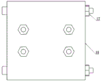
FIG. 4 is a top view of the full-automatic sucker type stacker crane based on machine vision
FIG. 5 is a front view of a sliding roller bearing according to the present invention
FIG. 6 is a sectional view of a sliding roller bearing according to the present invention
FIG. 7 is a front view of a lifting flitch plate in the full-automatic sucker type stacking crane based on machine vision according to the invention
FIG. 8 is a side view of a lifting flitch plate in the full-automatic sucker type stacker crane based on machine vision according to the invention
FIG. 9 is a connection diagram of a center-related control system of the full-automatic sucker type stacker crane based on machine vision
In the figure, a vacuum pump 1, a double-layer rubber vacuum sucker 2, a rotating motor 3, a micro telescopic push rod 4, a top plate 5, a reinforcing rib 6, a program control board 7, a sucker plate 8, a slide rail 9, a sliding roller bearing 10, a supporting leg 11, a Mecanum wheel 12, a lifting pasting plate 13, a motor roller 14, a sleeve 15, a bearing 16, a nut 17, a non-standard guide rail 18, a connecting plate 19, a driving motor 20 and a control chip plate 21.
The invention has the beneficial benefits that: this full-automatic sucking disc formula pile crane structural design based on machine vision is simple, low in production cost, and structural stability is strong, snatchs the object with the sucking disc and replaces traditional tongs and snatch the object, replaces the preceding cantilever crane that rises with the slip gyro wheel bearing, reduces the energy consumption and improves the security performance simultaneously. The carrier can be flexibly changed into a single group of multi-position suckers or a plurality of groups of multi-position suckers according to different application occasions. The full-automatic sucker type stacking crane based on machine vision can also run in parallel, a signal transmitting and receiving device, a positioning device, a sensor device and the like are installed on each transporter, interaction of multiple items of information such as pose information, basic information of goods, emergency degree of the goods and the like between two or more transporters is completed through communication technologies such as the Internet 5G and the like, and the multiple transporters carry out real-time path planning, emergency material priority, obstacle avoidance and other demand regulation according to the emergency degree of the goods, the distance between the transporters, fixed obstacle information, the priority of the goods and the like and according to self-main programs of the transporters. The investment cost, the space cost, the labor cost, the operation cost and the maintenance cost are saved to a great extent, and the unmanned, automatic and continuous production of factories is further realized.
The specific implementation mode is as follows:
as shown in fig. 1 to 9, the full-automatic sucker type stacker crane based on machine vision comprises four hollow tube support legs 11 and two cross frame support legs 11 as a frame of the full-automatic sucker type stacker crane, 6 reinforcing rib tubes 6 are added to prevent the frame support legs from splitting, the hollow tubes are connected through a three-way interface, driving motors 20 are respectively installed at the bottoms of the four support legs 11, and a mecanum wheel 12 is connected with the driving motors 20 to complete the assembly of the frame and the running mechanism of the full-automatic sucker type stacker crane; four rotary motor rollers 14 are arranged on the frame, the motor rollers 14 are arranged on the rotary shaft of the rotary motor 3, high elastic wires are arranged on the motor rollers 14, the other ends of the wires are connected with a lifting flitch 13, and the lifting flitch 13 is fixed on a sliding roller bearing 10; the sliding roller bearing 10 consists of a sleeve 15, bearings 16, nuts 17 and a non-standard guide rail 18, wherein the sleeve 15 is provided with the two bearings 16 which are fixed on the non-standard guide rail 18 through bolts and nuts 17, and the sliding roller bearing 10 is arranged on a slide rail 9 on a rack; the other side of the sliding roller bearing 10 is fixedly connected on a connecting plate 19, a middle lifting device is formed by connecting two connecting plates 19 through a top plate 5 to form a group of structures in the shape of an inverted U, a vacuum pump 1 is arranged on the top plate 5, an air pipe at the air suction end of the vacuum pump 1 is sequentially connected with six double-layer rubber vacuum suckers 2 through five T-shaped three-way plastic pipe quick connectors, two micro telescopic push rods 4 are arranged on the back surface of the connecting plate 19 where the sliding roller bearing 10 is arranged and fixedly connected on the connecting plate, sucker plates 8 are arranged on the tops of the two micro telescopic push rods 4, three double-layer rubber vacuum suckers 2 are arranged on the sucker plates 8, two micro telescopic push rods 4 are also arranged on the connecting plate 19 on the other side and fixedly connected on the connecting plate 19, the sucker plates 8 are arranged on the tops of the two push rods, three double-layer rubber vacuum suckers 2 are arranged on the sucker plates 8, and the other group of inverted U lifting mechanism is the same as the inverted U lifting mechanism, this is the sucking disc grabbing mode; when the characteristic information or two-dimensional code of a target to be grabbed is identified through a high-resolution camera arranged on a rack, the position information of the target material is fed back to a control chip board 21 arranged on a top plate, the control chip board 21 sends an instruction to control a motor matched with a Mecanum wheel 12 to work so as to enable a target area to approach, when a full-automatic sucker type stacking crane reaches the position above the target material, the high-resolution camera identifies that the material is in the range of a grabbing device, the control chip 21 sends an instruction to a rotating motor 3, a wire on a motor roller 14 is paid off through forward rotation of the rotating motor so as to realize descending of a lifting device, after the lifting device descends to the ground, the miniature telescopic push rods on two sides are controlled by a programmed program to stretch 4, the sucker board 1 is driven to approach the material inwards, the three groups of double-layer rubber vacuum suckers 2 approach the surface of the material, the vacuum pump 1 is operated to control the programmed program to start pumping for 2-4s, then the rotating motor 3 rotates reversely, the wire on the motor roller 14 starts to rotate and rise, the lifting flitch 13 drives the sliding roller bearing 10 to rise along the slide rail, and the first material taking is finished; meanwhile, the high-resolution camera starts to identify the material same as the target material next time, information is fed back to the control chip plate 21, an instruction is sent to move towards the next target material, when the high-resolution camera moves above the target material, the rotating motor 3 is controlled to rotate forwards, the motor roller 14 is controlled to pay off, the lifting pasting plate 13 drives the sliding roller bearing 10 to slide downwards along the slide rail 9, the material is placed and stacked above the target material, the vacuum pump 1 is controlled to deflate, the micro telescopic push rod 4 is controlled to retract, the sucker plate 8 is made to retreat, the rotating motor 3 is controlled to continue paying off, the lifting device continues to slide downwards, the micro telescopic push rod 4 is controlled to stretch after the material reaches the bottom layer, the double-layer rubber vacuum sucker 2 is attached to the surface of the target material, at the moment, objects are arranged on the first layer and the second layer, the vacuum pump 1 is controlled to start to pump air for 2-4s, the rotating motor 3 is controlled to reversely rotate to take up and drive the sliding roller bearing 10 to lift upwards along the slide rail 9, meanwhile, the high-resolution camera starts to identify the material which is the same as the captured target, the information is fed back to the control chip 21, and the Mecanum wheel 12 is controlled to move to the next target point; when the object reaches the top of the third object, the motor controls the rotating motor 3 to rotate forwards, the motor roller 14 releases the line, the lifting flitch drives the sliding roller bearing to slide downwards along the slide rail, the object is placed and stacked above the target object, the vacuum pump is controlled to deflate, the micro telescopic push rod 4 is controlled to retract, the sucker plate 8 is made to retract, the line is continuously released by controlling the rotating motor 3, the lifting device continuously slides downwards, the micro telescopic push rod 4 is controlled to stretch after the object reaches the bottom layer, the double-layer rubber vacuum sucker 2 is attached to the surface of the target object, at the moment, objects are arranged on the first layer, the second layer and the third layer, after the vacuum pump 1 starts to exhaust for 2-4s, the rotating motor 3 is controlled to reversely take up to drive the sliding roller bearing 10 to move upwards and lift along the slide rail 9, after the distance of 2-5cm from the ground, the Mecanum wheel 12 is controlled to run to the target stacking area, and meanwhile, the high-resolution camera starts to identify random obstacles and fixed obstacles appearing in the transportation process and feeds back to the control Optimized path planning and obstacle avoidance are performed in the chip board 21. After the target stacking point is reached, the motor controls the rotating motor 3 to rotate forwards, the motor roller 14 releases the line, the lifting flitch 13 drives the sliding roller bearing 10 to slide downwards along the slide rail 9, the lifting device falls on the ground, the vacuum pump 1 is controlled to deflate, the miniature telescopic push rod 4 is controlled to retract, the sucker plate 8 retreats, the double-layer vacuum sucker 2 is separated from the material, and the stacking and carrying machine retreats to the material carrying area to enter the next operation.
The invention can enable a plurality of conveyers to move in parallel, for example, the invention is applied to a logistics distribution center and transports logistics express items to warehouses in each provincial area; chemical raw materials are transported in a chemical plant workshop, so that casualties and error probability are reduced; the device is applied to occasions with high dangerous hazard labor intensity, such as transportation of materials in a multi-dust workshop and guarantee of personnel health.
Finally, it should be noted that: although the foregoing embodiments have been described in detail, it will be appreciated by those skilled in the art that many modifications may be made to the invention without departing from the spirit and scope of the invention as defined by the appended claims.
Claims (9)
1. Full-automatic sucking disc formula pile hoist based on machine vision, its characterized in that: including vacuum pump, double-deck rubber vacuum chuck, rotating electrical machines, miniature flexible push rod, roof, stiffening rib, program control board, sucking disc board, slide rail, slip gyro wheel bearing, landing leg, mecanum wheel, carry and draw flitch, motor drum, sleeve, bearing, nut, nonstandard guide rail, connecting plate, driving motor, control chip board, mainly divide into four component parts, do respectively: mechanical structure, control system, identification mode, grasping mode.
2. The machine vision based fully automatic suction cup stacker crane according to claim 1, characterized in that: the mechanical structure comprises a frame, a lifting mechanism and an operating mechanism, wherein the frame is provided with supporting legs, the lifting mechanism is used for fixedly connecting the slide rail on the frame vertically, the sliding roller bearing is sleeved on the slide rail and is connected with the connecting plate through a bolt, the sliding roller bearing is fixedly connected with the lifting and pulling part through a bolt, the lifting and pulling part is connected with a motor roller through a wire, the motor roller is fixed on a groove of a rotating motor, and the operating mechanism comprises a four-wheel drive Mecanum wheel.
3. The machine vision based fully automatic suction cup stacker crane according to claim 2, characterized in that: the lifting mechanism is fixed on the rack slide rail and vertically lifts.
4. The machine vision based fully automatic suction cup stacker crane according to claim 1, characterized in that: the grabbing mode comprises a sucker gripper, the sucker plate and the miniature telescopic push rod are fixedly connected onto the connecting plate, the double-layer rubber vacuum sucker is fixedly connected onto the sucker plate, and the vacuum pump is installed on the top plate.
5. The machine vision based fully automatic suction cup stacker crane according to claim 1, characterized in that: the control system comprises lifting control, operation control, grabbing control and stacking control.
6. The machine vision based fully automatic suction cup stacker crane according to claim 5, characterized in that: the control chip board is fixed on the top board, and the control chip is controlled independently.
7. The machine vision based fully automatic suction cup stacker crane according to claim 1, characterized in that: the identification mode can identify characteristic information and barriers on the material through the high-resolution camera.
8. The machine vision based fully automatic suction cup stacker crane according to claim 6, characterized in that: and a high-resolution camera is arranged on the frame.
9. The machine vision based fully automatic suction cup stacker crane according to claim 2, characterized in that: the frame is of a rectangular structure formed by hollow pipes, and the frame is provided with a reinforcing rib plate.
Priority Applications (1)
| Application Number | Priority Date | Filing Date | Title |
|---|---|---|---|
| CN202110541943.5A CN113415764A (en) | 2021-05-18 | 2021-05-18 | Full-automatic sucking disc formula pile hoist based on machine vision |
Applications Claiming Priority (1)
| Application Number | Priority Date | Filing Date | Title |
|---|---|---|---|
| CN202110541943.5A CN113415764A (en) | 2021-05-18 | 2021-05-18 | Full-automatic sucking disc formula pile hoist based on machine vision |
Publications (1)
| Publication Number | Publication Date |
|---|---|
| CN113415764A true CN113415764A (en) | 2021-09-21 |
Family
ID=77712509
Family Applications (1)
| Application Number | Title | Priority Date | Filing Date |
|---|---|---|---|
| CN202110541943.5A Pending CN113415764A (en) | 2021-05-18 | 2021-05-18 | Full-automatic sucking disc formula pile hoist based on machine vision |
Country Status (1)
| Country | Link |
|---|---|
| CN (1) | CN113415764A (en) |
Cited By (1)
| Publication number | Priority date | Publication date | Assignee | Title |
|---|---|---|---|---|
| CN114162555A (en) * | 2022-01-05 | 2022-03-11 | 安徽理工大学 | Intelligent carrying robot with visual tracking function and implementation method thereof |
Citations (7)
| Publication number | Priority date | Publication date | Assignee | Title |
|---|---|---|---|---|
| KR20100089210A (en) * | 2009-02-03 | 2010-08-12 | 성균관대학교산학협력단 | Multipurpose lift device for move style |
| CN107512679A (en) * | 2017-09-29 | 2017-12-26 | 北京正合慧视科技有限公司 | The operating method of gantry transfer robot and gantry transfer robot |
| CN207347083U (en) * | 2017-09-29 | 2018-05-11 | 北京正合慧视科技有限公司 | Gantry transfer robot |
| CN110642155A (en) * | 2019-08-30 | 2020-01-03 | 武汉理工大学 | Folding rail type gravity self-adaptive crane |
| CN211685400U (en) * | 2020-01-17 | 2020-10-16 | 东莞理工学院 | Intelligence material letter sorting transfer robot |
| CN212024035U (en) * | 2020-01-03 | 2020-11-27 | 同济大学 | Gantry type sucker hoisting device |
| CN213111563U (en) * | 2020-09-04 | 2021-05-04 | 苏州嘉米特自动化设备有限公司 | Pile up neatly device that facilitates use |
-
2021
- 2021-05-18 CN CN202110541943.5A patent/CN113415764A/en active Pending
Patent Citations (7)
| Publication number | Priority date | Publication date | Assignee | Title |
|---|---|---|---|---|
| KR20100089210A (en) * | 2009-02-03 | 2010-08-12 | 성균관대학교산학협력단 | Multipurpose lift device for move style |
| CN107512679A (en) * | 2017-09-29 | 2017-12-26 | 北京正合慧视科技有限公司 | The operating method of gantry transfer robot and gantry transfer robot |
| CN207347083U (en) * | 2017-09-29 | 2018-05-11 | 北京正合慧视科技有限公司 | Gantry transfer robot |
| CN110642155A (en) * | 2019-08-30 | 2020-01-03 | 武汉理工大学 | Folding rail type gravity self-adaptive crane |
| CN212024035U (en) * | 2020-01-03 | 2020-11-27 | 同济大学 | Gantry type sucker hoisting device |
| CN211685400U (en) * | 2020-01-17 | 2020-10-16 | 东莞理工学院 | Intelligence material letter sorting transfer robot |
| CN213111563U (en) * | 2020-09-04 | 2021-05-04 | 苏州嘉米特自动化设备有限公司 | Pile up neatly device that facilitates use |
Cited By (2)
| Publication number | Priority date | Publication date | Assignee | Title |
|---|---|---|---|---|
| CN114162555A (en) * | 2022-01-05 | 2022-03-11 | 安徽理工大学 | Intelligent carrying robot with visual tracking function and implementation method thereof |
| CN114162555B (en) * | 2022-01-05 | 2022-12-02 | 安徽理工大学 | Intelligent carrying robot with visual tracking function and implementation method thereof |
Similar Documents
| Publication | Publication Date | Title |
|---|---|---|
| CN107840059B (en) | Automatic reclaimer of two-way storage | |
| CN102190148B (en) | Automatic unstacking and conveying method for standard boxes | |
| CN105437204A (en) | Manipulator-loaded AGV trolley | |
| CN211768978U (en) | Panel hacking machine | |
| CN110606386A (en) | Intelligent loading and unloading system for containerized goods | |
| CN113460715B (en) | Intelligent quick-assembly system for containerized goods | |
| CN102502255A (en) | Automatic loading and unloading machine for composite board production line | |
| CN112758577B (en) | Multi-station storage, picking and stacking conveyor and stacking method | |
| CN213356134U (en) | Spinning cake stacking gantry and spinning cake stacking system | |
| CN113415764A (en) | Full-automatic sucking disc formula pile hoist based on machine vision | |
| CN206108467U (en) | A mechanical system that is used for flat -plate -shaped object of split transport | |
| CN109823846B (en) | Automatic stacking machine and automatic stacking method applied to feed packaging bags | |
| CN109292338B (en) | Automatic storing, taking and transferring system for industrial production process | |
| CN205184756U (en) | AGV dolly of loading manipulator | |
| CN203781356U (en) | Offline stacking system for building blocks | |
| CN202449615U (en) | Automatic loading/unloading machine for composite board production line | |
| CN110127256B (en) | Logistics trolley based on pneumatic grabbing and transportation method thereof | |
| CN210214137U (en) | Unstacker | |
| CN112478823A (en) | Automatic loading system and loading method thereof | |
| CN103863829A (en) | Building block off-line stacking system | |
| CN216038401U (en) | Tray storehouse automatic lifting device based on ore dressing medicament adds | |
| CN111137608A (en) | Stereoscopic warehouse | |
| CN206087455U (en) | Evaporate and press full -automatic packaging system of aerated concrete block | |
| CN214877556U (en) | Concrete block or plate storage system | |
| CN210944000U (en) | Intelligent loading and unloading system for containerized goods |
Legal Events
| Date | Code | Title | Description |
|---|---|---|---|
| PB01 | Publication | ||
| PB01 | Publication | ||
| SE01 | Entry into force of request for substantive examination | ||
| SE01 | Entry into force of request for substantive examination |