CN113200324B - Terminal outward appearance detects and equipment for packing - Google Patents
Terminal outward appearance detects and equipment for packing Download PDFInfo
- Publication number
- CN113200324B CN113200324B CN202110337706.7A CN202110337706A CN113200324B CN 113200324 B CN113200324 B CN 113200324B CN 202110337706 A CN202110337706 A CN 202110337706A CN 113200324 B CN113200324 B CN 113200324B
- Authority
- CN
- China
- Prior art keywords
- cylinder
- frame
- packaging
- lifting
- terminal
- Prior art date
- Legal status (The legal status is an assumption and is not a legal conclusion. Google has not performed a legal analysis and makes no representation as to the accuracy of the status listed.)
- Active
Links
Images


Classifications
-
- B—PERFORMING OPERATIONS; TRANSPORTING
- B65—CONVEYING; PACKING; STORING; HANDLING THIN OR FILAMENTARY MATERIAL
- B65G—TRANSPORT OR STORAGE DEVICES, e.g. CONVEYORS FOR LOADING OR TIPPING, SHOP CONVEYOR SYSTEMS OR PNEUMATIC TUBE CONVEYORS
- B65G47/00—Article or material-handling devices associated with conveyors; Methods employing such devices
- B65G47/22—Devices influencing the relative position or the attitude of articles during transit by conveyors
- B65G47/24—Devices influencing the relative position or the attitude of articles during transit by conveyors orientating the articles
- B65G47/248—Devices influencing the relative position or the attitude of articles during transit by conveyors orientating the articles by turning over or inverting them
-
- B—PERFORMING OPERATIONS; TRANSPORTING
- B07—SEPARATING SOLIDS FROM SOLIDS; SORTING
- B07C—POSTAL SORTING; SORTING INDIVIDUAL ARTICLES, OR BULK MATERIAL FIT TO BE SORTED PIECE-MEAL, e.g. BY PICKING
- B07C5/00—Sorting according to a characteristic or feature of the articles or material being sorted, e.g. by control effected by devices which detect or measure such characteristic or feature; Sorting by manually actuated devices, e.g. switches
- B07C5/34—Sorting according to other particular properties
-
- B—PERFORMING OPERATIONS; TRANSPORTING
- B07—SEPARATING SOLIDS FROM SOLIDS; SORTING
- B07C—POSTAL SORTING; SORTING INDIVIDUAL ARTICLES, OR BULK MATERIAL FIT TO BE SORTED PIECE-MEAL, e.g. BY PICKING
- B07C5/00—Sorting according to a characteristic or feature of the articles or material being sorted, e.g. by control effected by devices which detect or measure such characteristic or feature; Sorting by manually actuated devices, e.g. switches
- B07C5/36—Sorting apparatus characterised by the means used for distribution
- B07C5/361—Processing or control devices therefor, e.g. escort memory
- B07C5/362—Separating or distributor mechanisms
-
- B—PERFORMING OPERATIONS; TRANSPORTING
- B65—CONVEYING; PACKING; STORING; HANDLING THIN OR FILAMENTARY MATERIAL
- B65B—MACHINES, APPARATUS OR DEVICES FOR, OR METHODS OF, PACKAGING ARTICLES OR MATERIALS; UNPACKING
- B65B15/00—Attaching articles to cards, sheets, strings, webs, or other carriers
- B65B15/04—Attaching a series of articles, e.g. small electrical components, to a continuous web
-
- B—PERFORMING OPERATIONS; TRANSPORTING
- B65—CONVEYING; PACKING; STORING; HANDLING THIN OR FILAMENTARY MATERIAL
- B65G—TRANSPORT OR STORAGE DEVICES, e.g. CONVEYORS FOR LOADING OR TIPPING, SHOP CONVEYOR SYSTEMS OR PNEUMATIC TUBE CONVEYORS
- B65G47/00—Article or material-handling devices associated with conveyors; Methods employing such devices
- B65G47/74—Feeding, transfer, or discharging devices of particular kinds or types
- B65G47/90—Devices for picking-up and depositing articles or materials
- B65G47/902—Devices for picking-up and depositing articles or materials provided with drive systems incorporating rotary and rectilinear movements
Abstract
The invention relates to terminal appearance detection and packaging equipment, which comprises a rack and a product belt line, wherein the product belt line is positioned on one side of the upper end surface of the rack; the upper end face of the rack is provided with a turnover mechanism, a CCD detection mechanism, a defective product discharge mechanism, a swing arm carrying mechanism, a lifting carrying mechanism, a horizontal rotating mechanism and a bag feeding and packaging mechanism; the product belt line, the turnover mechanism, the CCD detection mechanism, the defective product discharge mechanism and the horizontal rotation mechanism are sequentially arranged along a straight line; the swing arm carrying mechanism corresponds to the upper and lower positions of the tail end of the product belt line, the turnover mechanism, the CCD detection mechanism, the defective product discharge mechanism and the horizontal rotating mechanism; the lifting and carrying mechanism corresponds to the upper and lower positions of the horizontal rotating mechanism. The invention integrates the appearance detection and the packaging operation of the terminal on the same equipment, greatly reduces the space occupation and the quantity of the equipment, simultaneously can save a mechanical arm robot, is beneficial to improving the working efficiency and reducing the production cost.
Description
Technical Field
The invention relates to detection and packaging of terminals, in particular to terminal appearance detection and packaging equipment.
Background
After the production and processing operation of the wiring terminal product is completed, appearance detection operation is required to be carried out, and then packaging is carried out to wait for shipment.
Outward appearance detection operation includes steps such as conveying, attitude adjustment and camera shooting, and the terminal that the packing operation need will accomplish the detection is put into the material area and is carried out the tectorial membrane operation, and consequently the detection of current terminal is mostly realized through two production lines with the packing to realize the transfer of terminal product through the manipulator robot between the production line.
However, two production lines can occupy more space undoubtedly, need great workshop side to hold to the equipment that the production line corresponds is more, and collocation manipulator robot can lead to the cost higher undoubtedly, and the longer migration distance of terminal product can restrict work efficiency simultaneously, is unfavorable for the benefit of enterprise.
Disclosure of Invention
The purpose of the invention is: the utility model provides a terminal outward appearance detects and equipment for packing, with the outward appearance detection of terminal and the collection of packing operation on same equipment, reduce the quantity to the occuping of space and equipment by a wide margin, can save the manipulator robot simultaneously, be favorable to improving work efficiency, reduction in production cost.
In order to achieve the above purpose, the present invention provides the following technical solutions:
a terminal appearance detecting and packaging device comprises a rack and a product belt line, wherein the product belt line is positioned on one side of the upper end surface of the rack; the upper end face of the rack is provided with a turnover mechanism, a CCD detection mechanism, a defective product discharge mechanism, a swing arm carrying mechanism, a lifting carrying mechanism, a horizontal rotating mechanism and a bag feeding and packaging mechanism; the product belt line, the turnover mechanism, the CCD detection mechanism, the defective product discharge mechanism and the horizontal rotation mechanism are sequentially arranged along a straight line; the swing arm carrying mechanism corresponds to the upper and lower positions of the tail end of the product belt line, the turnover mechanism, the CCD detection mechanism, the defective product discharging mechanism and the horizontal rotating mechanism; the lifting and carrying mechanisms correspond to the upper and lower positions of the horizontal rotating mechanism, and the two bag-in packaging mechanisms are respectively corresponding to the positions of two ends of the lifting and carrying mechanisms; the swing arm carrying mechanism comprises a reciprocating swing arm mechanism, a suction module and a clamping jaw cylinder; the reciprocating swing arm mechanism is positioned on the upper end face of the rack, the suction module and the clamping jaw air cylinder are both positioned at the bottom end of a movable rod of the reciprocating swing arm mechanism, the suction module is specifically positioned at one end of the movable rod, which faces a product belt line, and the clamping jaw air cylinders are arranged in a linear array along the length direction of the movable rod; the bag-feeding packaging mechanism comprises a material belt conveying line, a photoelectric sensor, a lifting pressing mechanism and a material belt conveying mechanism; the lifting pressing mechanism is located at the middle downstream position of the material belt conveying line, the material belt conveying mechanism is located at the downstream position of the material belt conveying line, and the tail end of the material belt conveying mechanism is provided with a winding frame; the lifting pressing mechanism comprises a connecting frame, a lifting plate and a pressing plate; the utility model discloses a material belt conveyor line, including connecting frame, lifter plate, be provided with the fifth cylinder on the connecting frame, the piston rod and the lifter plate of fifth cylinder are connected, the bottom of lifter plate is provided with the electric heat piece, press ironing plate and electric heat piece side to be connected, press the vertical setting of ironing plate and corresponding with the upper and lower position of material belt conveyor line.
Further, the turnover mechanism comprises a fixed seat, a turnover jig, a first air cylinder and a side positioning plate; the fixing base is located the frame up end, the upset tool passes through bearing and fixing base upper portion swing joint, be provided with the profile modeling locating piece on the upset tool, the one end of upset tool is provided with the trip bar, the cylinder body and the fixing base bottom of first cylinder are articulated, the piston rod of first cylinder is articulated with the trip bar through the linkage free bearing.
Further, the side positioning plate is movably connected with the overturning jig, and a gap is formed between the side positioning plate and the profiling positioning block; and a second cylinder is arranged on the overturning jig, and a piston rod of the second cylinder is connected with the side positioning plate.
Further, the CCD detection mechanism comprises a horizontal CCD module, a light source and a positioning jig; the light sources are positioned on two sides of the central frame, and the positioning jig is positioned at the top end of the central frame; the horizontal CCD module is positioned on one side, away from the center frame, of the light source, and the horizontal CCD module, the light source and the positioning jig are positioned on the same straight line.
Further, the defective product discharging mechanism comprises a third cylinder and a slide way; the third cylinder level sets up, the piston rod of third cylinder is connected with the lateral wall of slide, the opening of slide is up.
Further, lift transport mechanism includes support frame, carriage and crane, the support frame is located the frame up end, the top level of support frame is provided with belt servo module, the carriage is located belt servo module, be provided with the fourth cylinder on the carriage, crane and carriage swing joint, the piston rod and the crane of fourth cylinder are connected, be provided with clamping jaw revolving cylinder on the crane, clamping jaw revolving cylinder is corresponding with the upper and lower position of horizontal rotation mechanism and the head end of going into bag packagine machine structure.
Furthermore, horizontal rotating mechanism includes support and revolving cylinder, the support is located the frame up end, revolving cylinder level sets up on the support top, be provided with rotary jig on revolving cylinder's the rotary piston, rotary jig is central symmetry structure and both ends can fix a position a terminal product respectively.
The beneficial effects of the invention are as follows: the utility model provides a terminal outward appearance detects and equipment for packing, through to the product belt line, tilting mechanism, CCD detection mechanism, arrange defective products mechanism, swing arm transport mechanism, lift transport mechanism, horizontal rotation mechanism and go into bag packagine machine construct the configuration optimization design and integration arrangement, detect the outward appearance of terminal and pack the operation set on same equipment, compare in two original production lines and can reduce the quantity to the occupation in space and equipment by a wide margin, degree of automation is high, mechanical arm robot can be saved simultaneously, shorten the displacement of terminal product between each station, be favorable to improving work efficiency, and the production cost is reduced, the benefit of enterprise is improved.
Drawings
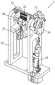
Fig. 1 is a schematic view of an overall structure of a terminal appearance inspection and packaging apparatus according to the present invention.
Fig. 2 is a schematic view of another perspective overall structure of the terminal appearance inspection and packaging apparatus according to the present invention.
Fig. 3 is a schematic view of a product belt line structure of a terminal appearance detecting and packaging device according to the present invention.
Fig. 4 is a schematic structural view of a turnover mechanism of the terminal appearance detecting and packaging apparatus according to the present invention.
Fig. 5 is a schematic structural view of a CCD detecting mechanism of the terminal appearance detecting and packaging apparatus of the present invention.
Fig. 6 is a schematic structural diagram of a defective product discharge mechanism of the terminal appearance inspection and packaging apparatus according to the present invention.
Fig. 7 is a schematic structural view of a swing arm conveying mechanism of the terminal appearance detecting and packaging apparatus according to the present invention.
Fig. 8 is a schematic structural view of a lifting and carrying mechanism of a terminal appearance detecting and packaging apparatus according to the present invention.
Fig. 9 is a schematic structural view of a horizontal rotation mechanism of a terminal appearance inspection and packaging apparatus according to the present invention.
Fig. 10 is a schematic structural view of a bag-in packaging mechanism of a terminal appearance detecting and packaging apparatus according to the present invention.
Fig. 11 is a schematic structural view of a lifting pressing mechanism of the terminal appearance detecting and packaging device of the present invention.
In the figure: 1. a frame; 2. a product belt line; 3. a turnover mechanism; 30. a fixed seat; 31. turning over the jig; 33. profiling positioning blocks; 34. linkage hinged support; 35. a first cylinder; 36. a side positioning plate; 37. a second cylinder; 4. a CCD detection mechanism; 41. a horizontal CCD module; 42. a center frame; 43. a light source; 44. positioning a jig; 5. a defective product discharge mechanism; 51. a third cylinder; 52. a slideway; 6. a swing arm carrying mechanism; 61. a reciprocating swing arm mechanism; 62. a suction module; 63. a clamping jaw cylinder; 7. a lifting and carrying mechanism; 71. a support frame; 72. a belt servo module; 73. a carriage; 74. a fourth cylinder; 75. a lifting frame; 76. a clamping jaw rotating cylinder; 8. a horizontal rotation mechanism; 81. a support; 82. a rotating cylinder; 83. rotating the jig; 9. a bagging and packaging mechanism; 91. a material belt conveying line; 92. a photosensor; 93. unwinding the frame; 94. a cover tape roller; 95. a lifting pressing mechanism; 951. a connecting frame; 952. a lifting plate; 953. an electric heating block; 954. pressing the ironing plate; 955. a fifth cylinder; 96. a material belt conveying mechanism; 97. and (5) a winding frame.
Detailed Description
In order to make the objects, technical solutions and advantages of the present invention more apparent, the present invention is described in further detail below with reference to the accompanying drawings and embodiments. It should be understood that the specific embodiments described herein are merely illustrative of the invention and are not intended to limit the invention.
Referring to fig. 1 to 11, the terminal appearance detecting and packaging device comprises a rack 1 and a product belt line 2, wherein the product belt line 2 is positioned on one side of the upper end surface of the rack 1; the upper end face of the frame 1 is provided with a turnover mechanism 3, a CCD detection mechanism 4, a defective product discharge mechanism 5, a swing arm carrying mechanism 6, a lifting carrying mechanism 7, a horizontal rotating mechanism 8 and a bag filling and packaging mechanism 9; the product belt line 2, the turnover mechanism 3, the CCD detection mechanism 4, the defective product discharge mechanism 5 and the horizontal rotation mechanism 8 are sequentially arranged along a straight line, the product belt line 2 is used for conveying terminal products, the turnover mechanism 3 is used for adjusting the postures of the terminal products, the CCD detection mechanism 4 is used for performing appearance detection on the terminal products, and the defective product discharge mechanism 5 is used for discharging the terminal products which are unqualified in appearance detection; the swing arm conveying mechanism 6 corresponds to the upper and lower positions of the tail end of the product belt line 2, the turnover mechanism 3, the CCD detection mechanism 4, the defective product discharge mechanism 5 and the horizontal rotation mechanism 8, and the swing arm conveying mechanism 6 is used for conveying terminal products among the stations; the lifting and carrying mechanism 7 corresponds to the upper and lower positions of the horizontal rotating mechanism 8, the lifting and carrying mechanism 7 is used for transferring the terminal products on the horizontal rotating mechanism 8 to the bag feeding and packaging mechanism 9, the bag feeding and packaging mechanisms 9 are two in number and correspond to the positions of the two ends of the lifting and carrying mechanism 7 respectively, and the bag feeding and packaging mechanism 9 is used for packaging the terminal products in the material belt.
The turnover mechanism 3 comprises a fixed seat 30, a turnover jig 31, a first air cylinder 35 and a side positioning plate 36; the fixing base 30 is located the 1 up end of frame, upset tool 31 passes through bearing and the upper portion swing joint of fixing base 30, be provided with profile modeling locating piece 32 on the upset tool 31, profile modeling locating piece 32 is used for fixing a position the terminal product, the one end of upset tool 31 is provided with upset pole 33, the cylinder body and the fixing base 30 bottom of first cylinder 35 are articulated, the piston rod of first cylinder 35 is articulated with upset pole 33 through linkage free bearing 34, first cylinder 35 is used for driving linkage free bearing 34 and then drives the upset of upset pole 33, realizes the upset of upset tool 31 to realize the posture adjustment of terminal product.
The side positioning plate 36 is movably connected with the overturning jig 31, and a gap is formed between the side positioning plate 36 and the profiling positioning block 32; the overturning jig 31 is provided with a second cylinder 37, a piston rod of the second cylinder 37 is connected with the side positioning plate 36, and the second cylinder 37 is used for driving the side positioning plate 36 to move in a reciprocating manner, so that the side positioning of the terminal product is realized.
The CCD detection mechanism 4 comprises a horizontal CCD module 41, a light source 43 and a positioning jig 44; the light sources 43 are positioned at two sides of the central frame 42, and the positioning jig 44 is positioned at the top end of the central frame 42; the horizontal CCD module 41 is located on one side, away from the center frame 42, of the light source 43, the horizontal CCD module 41, the light source 43 and the positioning jig 44 are located on the same straight line, the horizontal CCD module 41 is used for appearance detection of a terminal product, and the light source 43 is used for light supplement.
The defective product discharging mechanism 5 comprises a third air cylinder 51 and a slide way 52; the third air cylinder 51 is horizontally arranged, a piston rod of the third air cylinder 51 is connected with the side wall of the slide way 52, the opening of the slide way 52 faces upwards, the third air cylinder 51 is used for driving the slide way 52 to horizontally move, and the slide way 52 is used for enabling unqualified terminal products to fall down.
The swing arm carrying mechanism 6 comprises a reciprocating swing arm mechanism 61, an absorption module 62 and a clamping jaw cylinder 63; reciprocal swing arm mechanism 61 is located 1 up end of frame, it all is located the movable rod bottom of reciprocal swing arm mechanism 61 to absorb module 62 and clamping jaw cylinder 63, absorb module 62 and specifically be located the movable rod towards the one end of product belt line 2, absorb module 62 and be used for absorbing the terminal product through the sucking disc, clamping jaw cylinder 63 is arranged along the length direction alignment form of movable rod, and clamping jaw cylinder 63 is used for pressing from both sides tightly and unclamp the terminal product.
The lift handling mechanism 7 includes support frame 71, carriage 73 and crane 75, the support frame 75 is located 1 up end of frame, the top level of support frame 71 is provided with belt servo module 72, carriage 73 is located belt servo module 72, and belt servo module 72 is used for driving carriage 73 horizontal migration, be provided with fourth cylinder 74 on the carriage 73, crane 75 and carriage 73 swing joint, the piston rod of fourth cylinder 74 is connected with crane 75, and fourth cylinder 74 is used for driving crane 75 to leave lift removal, be provided with clamping jaw revolving cylinder 76 on the crane 75, clamping jaw revolving cylinder 76 is corresponding with horizontal rotation mechanism 8 and the upper and lower position of income bag packagine machine mechanism 9's head end, and clamping jaw revolving cylinder 76 is used for pressing from both sides tightly and unclamping the terminal product.
The bag-feeding packaging mechanism 9 comprises a material belt conveying line 91, a photoelectric sensor 92, a lifting pressing mechanism 95 and a material belt conveying mechanism 96; the utility model discloses a material area transmission line 91, including material area transmission line 91, photoelectric sensor 92, conveyer belt 92, lift pressing mechanism 95, photoelectric sensor 92, conveyer belt 91, conveyer belt 97, conveyer belt 96, conveyer belt 97, conveyer belt 91, conveyer belt 95, conveyer belt 91, conveyer belt 97, conveyer belt 91, conveyer belt 95, conveyer belt 97, conveyer belt, and conveyer belt, and conveyer belt, and conveyer belt, and conveyer belt, and conveyer belt, and conveyer belt, and are used for the, and the rolling, respectively, are used for realizing the following, respectively, and the following, respectively, and the following, of following, and are used for realizing the following, of following, and are all of following, and are used for the following, respectively, and are used for the following, and are provided, respectively, and are provided, respectively, and are provided.
The lifting pressing mechanism 95 comprises a connecting frame 951, a lifting plate 952 and a pressing plate 954; the link 951 is connected with material belt transmission line 91, lifter plate 952 and link 951 swing joint, be provided with fifth cylinder 955 on the link 951, the piston rod of fifth cylinder 955 is connected with lifter plate 952, lifter plate 952's bottom is provided with electric heat piece 953, press ironing board 954 and electric heat piece 953 side connection, press ironing board 954 vertical setting and corresponding with the upper and lower position of material belt transmission line 91.
The working principle of the invention is as follows: the terminal products which are produced and processed are conveyed to the tail end in the product belt line 2, and the suction module 62 of the swing arm conveying mechanism 6 sucks the terminal products through the suction disc and moves the terminal products to the overturning jig 31 of the overturning mechanism 3; the profiling positioning block 32 positions the terminal product, a piston rod of the second air cylinder 37 extends out, and the driving side positioning plate 36 slides, so that the side face of the terminal product is positioned; then, the piston rod of the first air cylinder 35 drives the linkage hinged support 34 to drive the turnover rod 33 to turn over, so that the turnover jig 31 is turned over until the turnover jig turns over 90 degrees, and the posture of the terminal product is adjusted; then, a clamping jaw air cylinder 63 of the swing arm carrying mechanism 6 clamps the terminal product from the turnover mechanism 3 to a positioning jig 44 of the CCD detecting mechanism 4, a light source 43 starts to polish, and two horizontal CCD modules 41 perform appearance detection on two side faces of the terminal product; then, a clamping jaw air cylinder 63 of the swing arm carrying mechanism 6 moves the terminal product from the positioning jig 44 to the position above the defective product discharging mechanism 5, if the terminal product is judged to be a defective product through appearance detection, the third air cylinder 51 drives the slide rail 52 to move, the clamping jaw air cylinder 63 loosens the terminal product, and the terminal product can fall into the slide rail to be removed; if the product is qualified, the product is moved to a rotary jig 83 of the horizontal rotary mechanism 8; the rotary cylinder 82 drives the rotary jig 83 to horizontally rotate by 90 degrees, and the belt servo mechanism 72 and the fourth cylinder 74 of the lifting and carrying mechanism 7 are matched with the driving clamping jaw rotary cylinder 76 to move, so that the clamping jaw rotary cylinder 76 clamps the terminal product and moves to the bag-entering packaging mechanism 9, specifically, the terminal product is placed in a product placing groove of the material belt on the material belt conveying line 91; then the material belt conveying mechanism 96 drives the material belt to horizontally move along the material belt conveying line 91, the unwinding frame 93 discharges the film, the belt cover roller 94 presses the film on the top end of the material belt, and then the lifting pressing mechanism 95 presses the film on the material belt; the method specifically comprises the following steps: resistance circular telegram in the electric heat piece 953 generates heat to on pressing hot plate 954 with heat transfer, fifth cylinder 955 drive lifter plate 952 descends afterwards, realizes pressing hot plate 954 to compressing tightly of film, thereby presses the hot plate on the material area with the film, realizes the packing involution, accomplishes the packing.
In the present invention, unless otherwise explicitly stated or limited, the terms "connected," "fixed," and the like are to be construed broadly and may, for example, be fixedly connected, detachably connected, or integrated; can be mechanically or electrically connected; either directly or indirectly through intervening media, either internally or in any other relationship. The specific meanings of the above terms in the present invention can be understood according to specific situations by those of ordinary skill in the art.
The above examples are intended to further illustrate the present invention, but are not intended to limit the invention to these specific embodiments. Any modification, equivalent replacement, and improvement made within the spirit and principle of the present invention should be understood to be within the protection scope of the present invention.
Claims (7)
1. A terminal appearance detecting and packaging device comprises a rack and a product belt line, wherein the product belt line is positioned on one side of the upper end surface of the rack; the method is characterized in that: the upper end face of the rack is provided with a turnover mechanism, a CCD detection mechanism, a defective product discharge mechanism, a swing arm carrying mechanism, a lifting carrying mechanism, a horizontal rotating mechanism and a bag feeding and packaging mechanism; the product belt line, the turnover mechanism, the CCD detection mechanism, the defective product discharge mechanism and the horizontal rotation mechanism are sequentially arranged along a straight line; the swing arm carrying mechanism corresponds to the upper and lower positions of the tail end of the product belt line, the turnover mechanism, the CCD detection mechanism, the defective product discharge mechanism and the horizontal rotating mechanism; the lifting and carrying mechanisms correspond to the upper and lower positions of the horizontal rotating mechanism, and the two bag-in packaging mechanisms are respectively corresponding to the positions of two ends of the lifting and carrying mechanisms; the swing arm carrying mechanism comprises a reciprocating swing arm mechanism, a suction module and a clamping jaw cylinder; the reciprocating swing arm mechanism is positioned on the upper end face of the rack, the suction module and the clamping jaw air cylinder are both positioned at the bottom end of a movable rod of the reciprocating swing arm mechanism, the suction module is specifically positioned at one end of the movable rod, which faces a product belt line, and the clamping jaw air cylinders are arranged in a linear array along the length direction of the movable rod; the bag-feeding packaging mechanism comprises a material belt conveying line, a photoelectric sensor, a lifting pressing mechanism and a material belt conveying mechanism; the material belt conveying line is positioned on the upper end face of the rack, the photoelectric sensor is positioned above the upstream end of the material belt conveying line, an unwinding frame and a belt covering roller are arranged at the midstream position of the material belt conveying line, the lifting pressing mechanism is positioned at the midstream and downstream positions of the material belt conveying line, the material belt conveying mechanism is positioned at the downstream position of the material belt conveying line, and a winding frame is arranged at the tail end of the material belt conveying mechanism; the lifting pressing mechanism comprises a connecting frame, a lifting plate and a pressing plate; the utility model discloses a material belt conveyor line, including connecting frame, lifter plate, be provided with the fifth cylinder on the connecting frame, the piston rod and the lifter plate of fifth cylinder are connected, the bottom of lifter plate is provided with the electric heat piece, press ironing plate and electric heat piece side to be connected, press the vertical setting of ironing plate and corresponding with the upper and lower position of material belt conveyor line.
2. The apparatus for inspecting and packaging appearance of terminal as claimed in claim 1, wherein: the turnover mechanism comprises a fixed seat, a turnover jig, a first air cylinder and a side positioning plate; the fixing base is located the frame up end, the upset tool passes through bearing and fixing base upper portion swing joint, be provided with the profile modeling locating piece on the upset tool, the one end of upset tool is provided with the trip bar, the cylinder body and the fixing base bottom of first cylinder are articulated, the piston rod of first cylinder is articulated with the trip bar through the linkage free bearing.
3. The apparatus for inspecting and packaging appearance of terminal as claimed in claim 2, wherein: the side positioning plate is movably connected with the overturning jig, and a gap is formed between the side positioning plate and the profiling positioning block; and a second cylinder is arranged on the overturning jig, and a piston rod of the second cylinder is connected with the side positioning plate.
4. The apparatus for inspecting and packaging terminal appearance according to claim 3, wherein: the CCD detection mechanism comprises a horizontal CCD module, a light source and a positioning jig; the light sources are positioned on two sides of the central frame, and the positioning jig is positioned at the top end of the central frame; the horizontal CCD module is positioned on one side, away from the center frame, of the light source, and the horizontal CCD module, the light source and the positioning jig are positioned on the same straight line.
5. The terminal appearance inspection and packaging apparatus of claim 4, wherein: the defective product discharging mechanism comprises a third cylinder and a slide way; the third cylinder level sets up, the piston rod of third cylinder is connected with the lateral wall of slide, the opening of slide is up.
6. The apparatus for inspecting and packaging terminal appearance according to claim 5, wherein: the lifting and carrying mechanism comprises a support frame, a sliding frame and a lifting frame, the support frame is located on the upper end face of the machine frame, a belt servo module is horizontally arranged at the top end of the support frame, the sliding frame is located on the belt servo module, a fourth cylinder is arranged on the sliding frame, the lifting frame is movably connected with the sliding frame, a piston rod of the fourth cylinder is connected with the lifting frame, a clamping jaw rotating cylinder is arranged on the lifting frame, and the clamping jaw rotating cylinder corresponds to the upper position and the lower position of the head end of the bag-entering packaging mechanism and the horizontal rotating mechanism.
7. The apparatus for inspecting and packaging terminal appearance according to claim 6, wherein: the horizontal rotating mechanism comprises a support and a rotating cylinder, the support is located on the upper end face of the rack, the rotating cylinder is horizontally arranged at the top end of the support, a rotating jig is arranged on a rotating piston of the rotating cylinder, the rotating jig is of a central symmetry structure, and two ends of the rotating jig can be respectively used for positioning a terminal product.
Priority Applications (1)
| Application Number | Priority Date | Filing Date | Title |
|---|---|---|---|
| CN202110337706.7A CN113200324B (en) | 2021-03-30 | 2021-03-30 | Terminal outward appearance detects and equipment for packing |
Applications Claiming Priority (1)
| Application Number | Priority Date | Filing Date | Title |
|---|---|---|---|
| CN202110337706.7A CN113200324B (en) | 2021-03-30 | 2021-03-30 | Terminal outward appearance detects and equipment for packing |
Publications (2)
| Publication Number | Publication Date |
|---|---|
| CN113200324A CN113200324A (en) | 2021-08-03 |
| CN113200324B true CN113200324B (en) | 2022-07-19 |
Family
ID=77025874
Family Applications (1)
| Application Number | Title | Priority Date | Filing Date |
|---|---|---|---|
| CN202110337706.7A Active CN113200324B (en) | 2021-03-30 | 2021-03-30 | Terminal outward appearance detects and equipment for packing |
Country Status (1)
| Country | Link |
|---|---|
| CN (1) | CN113200324B (en) |
Families Citing this family (2)
| Publication number | Priority date | Publication date | Assignee | Title |
|---|---|---|---|---|
| CN114104374A (en) * | 2021-11-30 | 2022-03-01 | 广东联基精密工业有限公司 | USB connector automated inspection packagine machine |
| CN114308693B (en) * | 2021-12-10 | 2023-07-07 | 昆山市富德隆智能科技有限公司 | Automatic USB female head assembling, detecting and packaging machine |
Family Cites Families (6)
| Publication number | Priority date | Publication date | Assignee | Title |
|---|---|---|---|---|
| CN103746137B (en) * | 2013-12-16 | 2016-01-27 | 周俊雄 | Soft-package battery packing producing line |
| CN107082149A (en) * | 2017-05-05 | 2017-08-22 | 北京航天斯达科技有限公司 | A kind of infusion bag automatic turning sorting system |
| CN208214587U (en) * | 2018-04-28 | 2018-12-11 | 东莞金稞电子科技有限公司 | A kind of engraving overturning jig structure |
| CN109622391A (en) * | 2018-12-28 | 2019-04-16 | 广州广为自动化技术有限公司 | A kind of band automatic material taking detection packaging facilities |
| CN209905231U (en) * | 2019-04-04 | 2020-01-07 | 东莞市科晟电子有限公司 | Automatic detection packaging machine |
| CN111114926A (en) * | 2020-01-24 | 2020-05-08 | 深圳市科昭科技有限公司 | Full-automatic touch screen detection packaging equipment and control method thereof |
-
2021
- 2021-03-30 CN CN202110337706.7A patent/CN113200324B/en active Active
Also Published As
| Publication number | Publication date |
|---|---|
| CN113200324A (en) | 2021-08-03 |
Similar Documents
| Publication | Publication Date | Title |
|---|---|---|
| CN113200324B (en) | Terminal outward appearance detects and equipment for packing | |
| CN113794083A (en) | Automatic pin inserting equipment for carrier | |
| CN111993055B (en) | Battery positive electrode welding automatic production equipment and battery | |
| CN111591754A (en) | Shaft part conveying robot | |
| CN107986026A (en) | A kind of full-automatic mechanical hand equipment | |
| CN108878949A (en) | New energy battery automatic adhesive sticking machine | |
| CN108808100A (en) | Lithium battery pole ear bonding machine | |
| CN107344635A (en) | A kind of clinical thermometer labeling packing machine and its labeling packing method | |
| CN112845177A (en) | Box label and automatic appearance detection equipment | |
| CN111975358A (en) | Full-automatic assembly machine for sleeve screws | |
| CN108480907A (en) | A kind of lithium battery pole ear bonding machine | |
| CN216085670U (en) | Automatic pin inserting equipment for carrier | |
| CN108247343B (en) | Automatic assembly machine for dial potentiometer | |
| CN207698776U (en) | A kind of fully automatic manipulator equipment | |
| CN214865377U (en) | Box label and automatic appearance detection equipment | |
| CN207089715U (en) | A kind of clinical thermometer labels packing machine | |
| CN219340609U (en) | Automatic feeding and discharging mechanism of production line | |
| CN212196142U (en) | Automatic multilayer blank arranging and boxing machine for magnetic materials | |
| CN210881102U (en) | Automatic bottom box feeding machine | |
| CN213893168U (en) | Detection packaging device | |
| CN211889811U (en) | Full-automatic key assembling machine | |
| CN112331899A (en) | Power battery module production line | |
| CN110561831A (en) | Automatic bottom box feeding machine | |
| CN117228328B (en) | Automatic frame discharging equipment for burnt product | |
| CN218156081U (en) | Battery piece grid line detection device |
Legal Events
| Date | Code | Title | Description |
|---|---|---|---|
| PB01 | Publication | ||
| PB01 | Publication | ||
| SE01 | Entry into force of request for substantive examination | ||
| SE01 | Entry into force of request for substantive examination | ||
| GR01 | Patent grant | ||
| GR01 | Patent grant |