CN112960221B - Full-automatic packing pile up neatly production line - Google Patents
Full-automatic packing pile up neatly production line Download PDFInfo
- Publication number
- CN112960221B CN112960221B CN202110143845.6A CN202110143845A CN112960221B CN 112960221 B CN112960221 B CN 112960221B CN 202110143845 A CN202110143845 A CN 202110143845A CN 112960221 B CN112960221 B CN 112960221B
- Authority
- CN
- China
- Prior art keywords
- driving
- power device
- materials
- bracket
- conveying
- Prior art date
- Legal status (The legal status is an assumption and is not a legal conclusion. Google has not performed a legal analysis and makes no representation as to the accuracy of the status listed.)
- Active
Links
Images


Classifications
-
- B—PERFORMING OPERATIONS; TRANSPORTING
- B65—CONVEYING; PACKING; STORING; HANDLING THIN OR FILAMENTARY MATERIAL
- B65B—MACHINES, APPARATUS OR DEVICES FOR, OR METHODS OF, PACKAGING ARTICLES OR MATERIALS; UNPACKING
- B65B65/00—Details peculiar to packaging machines and not otherwise provided for; Arrangements of such details
- B65B65/003—Packaging lines, e.g. general layout
-
- B—PERFORMING OPERATIONS; TRANSPORTING
- B65—CONVEYING; PACKING; STORING; HANDLING THIN OR FILAMENTARY MATERIAL
- B65B—MACHINES, APPARATUS OR DEVICES FOR, OR METHODS OF, PACKAGING ARTICLES OR MATERIALS; UNPACKING
- B65B1/00—Packaging fluent solid material, e.g. powders, granular or loose fibrous material, loose masses of small articles, in individual containers or receptacles, e.g. bags, sacks, boxes, cartons, cans, or jars
- B65B1/04—Methods of, or means for, filling the material into the containers or receptacles
- B65B1/10—Methods of, or means for, filling the material into the containers or receptacles by rotary feeders
- B65B1/12—Methods of, or means for, filling the material into the containers or receptacles by rotary feeders of screw type
-
- B—PERFORMING OPERATIONS; TRANSPORTING
- B65—CONVEYING; PACKING; STORING; HANDLING THIN OR FILAMENTARY MATERIAL
- B65B—MACHINES, APPARATUS OR DEVICES FOR, OR METHODS OF, PACKAGING ARTICLES OR MATERIALS; UNPACKING
- B65B1/00—Packaging fluent solid material, e.g. powders, granular or loose fibrous material, loose masses of small articles, in individual containers or receptacles, e.g. bags, sacks, boxes, cartons, cans, or jars
- B65B1/30—Devices or methods for controlling or determining the quantity or quality or the material fed or filled
-
- B—PERFORMING OPERATIONS; TRANSPORTING
- B65—CONVEYING; PACKING; STORING; HANDLING THIN OR FILAMENTARY MATERIAL
- B65B—MACHINES, APPARATUS OR DEVICES FOR, OR METHODS OF, PACKAGING ARTICLES OR MATERIALS; UNPACKING
- B65B43/00—Forming, feeding, opening or setting-up containers or receptacles in association with packaging
- B65B43/12—Feeding flexible bags or carton blanks in flat or collapsed state; Feeding flat bags connected to form a series or chain
- B65B43/14—Feeding individual bags or carton blanks from piles or magazines
- B65B43/16—Feeding individual bags or carton blanks from piles or magazines by grippers
- B65B43/18—Feeding individual bags or carton blanks from piles or magazines by grippers by suction-operated grippers
-
- B—PERFORMING OPERATIONS; TRANSPORTING
- B65—CONVEYING; PACKING; STORING; HANDLING THIN OR FILAMENTARY MATERIAL
- B65B—MACHINES, APPARATUS OR DEVICES FOR, OR METHODS OF, PACKAGING ARTICLES OR MATERIALS; UNPACKING
- B65B43/00—Forming, feeding, opening or setting-up containers or receptacles in association with packaging
- B65B43/26—Opening or distending bags; Opening, erecting, or setting-up boxes, cartons, or carton blanks
-
- B—PERFORMING OPERATIONS; TRANSPORTING
- B65—CONVEYING; PACKING; STORING; HANDLING THIN OR FILAMENTARY MATERIAL
- B65B—MACHINES, APPARATUS OR DEVICES FOR, OR METHODS OF, PACKAGING ARTICLES OR MATERIALS; UNPACKING
- B65B51/00—Devices for, or methods of, sealing or securing package folds or closures; Devices for gathering or twisting wrappers, or necks of bags
- B65B51/04—Applying separate sealing or securing members, e.g. clips
- B65B51/07—Sewing or stitching
-
- B—PERFORMING OPERATIONS; TRANSPORTING
- B65—CONVEYING; PACKING; STORING; HANDLING THIN OR FILAMENTARY MATERIAL
- B65B—MACHINES, APPARATUS OR DEVICES FOR, OR METHODS OF, PACKAGING ARTICLES OR MATERIALS; UNPACKING
- B65B57/00—Automatic control, checking, warning, or safety devices
- B65B57/02—Automatic control, checking, warning, or safety devices responsive to absence, presence, abnormal feed, or misplacement of binding or wrapping material, containers, or packages
-
- B—PERFORMING OPERATIONS; TRANSPORTING
- B65—CONVEYING; PACKING; STORING; HANDLING THIN OR FILAMENTARY MATERIAL
- B65B—MACHINES, APPARATUS OR DEVICES FOR, OR METHODS OF, PACKAGING ARTICLES OR MATERIALS; UNPACKING
- B65B61/00—Auxiliary devices, not otherwise provided for, for operating on sheets, blanks, webs, binding material, containers or packages
- B65B61/24—Auxiliary devices, not otherwise provided for, for operating on sheets, blanks, webs, binding material, containers or packages for shaping or reshaping completed packages
-
- B—PERFORMING OPERATIONS; TRANSPORTING
- B65—CONVEYING; PACKING; STORING; HANDLING THIN OR FILAMENTARY MATERIAL
- B65B—MACHINES, APPARATUS OR DEVICES FOR, OR METHODS OF, PACKAGING ARTICLES OR MATERIALS; UNPACKING
- B65B63/00—Auxiliary devices, not otherwise provided for, for operating on articles or materials to be packaged
- B65B63/08—Auxiliary devices, not otherwise provided for, for operating on articles or materials to be packaged for heating or cooling articles or materials to facilitate packaging
-
- B—PERFORMING OPERATIONS; TRANSPORTING
- B65—CONVEYING; PACKING; STORING; HANDLING THIN OR FILAMENTARY MATERIAL
- B65B—MACHINES, APPARATUS OR DEVICES FOR, OR METHODS OF, PACKAGING ARTICLES OR MATERIALS; UNPACKING
- B65B7/00—Closing containers or receptacles after filling
- B65B7/02—Closing containers or receptacles deformed by, or taking-up shape, of, contents, e.g. bags, sacks
-
- B—PERFORMING OPERATIONS; TRANSPORTING
- B65—CONVEYING; PACKING; STORING; HANDLING THIN OR FILAMENTARY MATERIAL
- B65D—CONTAINERS FOR STORAGE OR TRANSPORT OF ARTICLES OR MATERIALS, e.g. BAGS, BARRELS, BOTTLES, BOXES, CANS, CARTONS, CRATES, DRUMS, JARS, TANKS, HOPPERS, FORWARDING CONTAINERS; ACCESSORIES, CLOSURES, OR FITTINGS THEREFOR; PACKAGING ELEMENTS; PACKAGES
- B65D88/00—Large containers
- B65D88/54—Large containers characterised by means facilitating filling or emptying
- B65D88/64—Large containers characterised by means facilitating filling or emptying preventing bridge formation
- B65D88/68—Large containers characterised by means facilitating filling or emptying preventing bridge formation using rotating devices
-
- B—PERFORMING OPERATIONS; TRANSPORTING
- B65—CONVEYING; PACKING; STORING; HANDLING THIN OR FILAMENTARY MATERIAL
- B65G—TRANSPORT OR STORAGE DEVICES, e.g. CONVEYORS FOR LOADING OR TIPPING, SHOP CONVEYOR SYSTEMS OR PNEUMATIC TUBE CONVEYORS
- B65G61/00—Use of pick-up or transfer devices or of manipulators for stacking or de-stacking articles not otherwise provided for
-
- Y—GENERAL TAGGING OF NEW TECHNOLOGICAL DEVELOPMENTS; GENERAL TAGGING OF CROSS-SECTIONAL TECHNOLOGIES SPANNING OVER SEVERAL SECTIONS OF THE IPC; TECHNICAL SUBJECTS COVERED BY FORMER USPC CROSS-REFERENCE ART COLLECTIONS [XRACs] AND DIGESTS
- Y02—TECHNOLOGIES OR APPLICATIONS FOR MITIGATION OR ADAPTATION AGAINST CLIMATE CHANGE
- Y02W—CLIMATE CHANGE MITIGATION TECHNOLOGIES RELATED TO WASTEWATER TREATMENT OR WASTE MANAGEMENT
- Y02W30/00—Technologies for solid waste management
- Y02W30/50—Reuse, recycling or recovery technologies
- Y02W30/62—Plastics recycling; Rubber recycling
Abstract
The invention relates to a full-automatic packaging and stacking production line; the method is characterized in that: the automatic packaging machine comprises a first conveying mechanism for conveying packaging bags, a second conveying mechanism for conveying materials, a packaging mechanism for bagging the materials, a detection mechanism for detecting the bagged materials, a sorting mechanism for screening unqualified materials, a shaping mechanism for shaping the bagged materials and a stacking mechanism for stacking the bagged materials on a tray; the packaging mechanism is arranged at the discharge hole of the second conveying mechanism; the packaging bags are stacked at one end of the first conveying mechanism, and the other end of the first conveying mechanism is close to the packaging mechanism; the detection mechanism, the sorting mechanism and the shaping mechanism are sequentially arranged between the packaging mechanism and the stacking mechanism. The problem of the production line that current scheme caused exist manual operation and lead to production line production efficiency lower and production line to use manipulator removal material to make production line use cost higher etc is solved.
Description
Technical Field
The invention relates to a production line, in particular to a full-automatic packaging and stacking production line.
Background
Generally, at present, powder, granule and block materials (such as plastics, chemical fertilizers, synthetic rubber, grains and the like) are weighed, bagged, sealed, poured and shaped, subjected to metal detection and stacked. Different devices are often used to operate separately. The transportation is carried out manually between different devices. This results in a less efficient palletization of the material packages. Some steps are still performed manually, which also results in poor packaging and palletizing quality.
Through the use of the automatic packaging and stacking production line, the production cost is reduced, the product quality of enterprises is improved, the profits of the enterprises are improved, and the products of the enterprises have market competitiveness. The automatic flour packing and stacking production line can liberate people from heavy physical labor, partial mental labor and severe and dangerous working environments, greatly improves the labor productivity and reduces the cost input. But the existing automatic packaging and stacking production line is a special customized production line and is difficult to upgrade and reform. And the automatic packaging and stacking production line uses a large number of heavy mechanical arms, so that the use cost of the production line is high. How to solve the above problems becomes crucial.
According to the existing scheme, a quantitative scale is adopted to fill materials into a packaging bag, the materials after being bagged are moved through a conveyor, the conveyor is provided with manual stations and mechanical stations in a staggered mode, the manual stations are used for bag sealing, metal detection and other operations, and the mechanical stations are used for recovering unqualified materials and stacking materials through a mechanical arm. Such a solution has the following problems: (1) the production line has manual operation, so that the production efficiency of the production line is low; (2) the production line uses the manipulator to remove the material for production line use cost is higher.
Disclosure of Invention
Aiming at the defects of the prior art, the invention discloses a full-automatic packaging and stacking production line, which aims to solve the problems that the production line in the prior art is low in production efficiency due to manual operation, high in use cost due to the fact that a manipulator is used for moving materials in the production line, and the like.
The technical scheme adopted by the invention is as follows:
a full-automatic packaging and stacking production line;
the automatic packaging machine comprises a first conveying mechanism for conveying packaging bags, a second conveying mechanism for conveying materials, a packaging mechanism for bagging the materials, a detection mechanism for detecting the bagged materials, a sorting mechanism for screening unqualified materials, a shaping mechanism for shaping the bagged materials and a stacking mechanism for stacking the bagged materials on a tray; the packaging mechanism is arranged at the discharge hole of the second conveying mechanism; the packaging bags are stacked at one end of the first conveying mechanism, and the other end of the first conveying mechanism is close to the packaging mechanism; the detection mechanism, the sorting mechanism and the shaping mechanism are sequentially arranged between the packaging mechanism and the stacking mechanism;
the shaping mechanism comprises a fourth conveying device for moving the bagged materials, a main pressure device for flattening the bagged materials, a side pressure device for side pressure of the bagged materials, a printing device for printing labels, a recovery device for recovering waste materials of the labels, an adsorption cylinder for adsorbing the labels and a second driving device for driving the adsorption cylinder to move; the main pressing device comprises main pressing plates which are arranged on two sides of the fourth conveying device in a parallel swinging mode, a main pressing block for flattening the bagged materials, a first vibrator for driving the main pressing block to vibrate, a fifteenth power device for pushing the main pressing plate, a first elastic device for propping the main pressing plate, a sliding piece for slidably supporting the main pressing plate and a first supporting roller for supporting the main pressing plate in a rolling mode; the main pressing plate is connected with the main pressing block in a swinging mode; the first vibrator is arranged on the main pressing block; the first elastic devices are arranged on two sides of the fourth conveying device in parallel; the sliding pieces are arranged on two sides of the fourth conveying device in a sliding mode; the sliding piece is connected with the fifteenth power device driving end; the first supporting roller is rotatably arranged on the sliding piece; the lateral pressing device comprises a lateral pressing block for laterally pressing the bagged materials, a ball for rolling and supporting the lateral pressing block, a sixteenth power device for driving the lateral pressing block to move, a second vibrator for driving the lateral pressing block to vibrate, a step block arranged on the lateral pressing block, a connecting block arranged at the driving end of the sixteenth power device and a second elastic device for elastically supporting the step block; the balls are arranged on the side pressing block in a parallel rotating mode and close to one end of the fourth conveying device; the second vibrator is arranged on the side pressing block; a stepped groove is formed in the connecting block; the second elastic device is arranged in the stepped groove; the step block is embedded into the step groove; the recovery device comprises a recovery support, a recovery wheel and a seventeenth power device, wherein the recovery wheel is arranged on the recovery support in a parallel rotating mode, and the seventeenth power device drives the recovery wheel to rotate; the label waste is wound on the recycling wheel; the seventeenth power device is arranged on the recovery bracket; a plurality of adsorption holes are formed around the adsorption cylinder; a plurality of adsorption spaces are formed in the adsorption cylinder; the adsorption holes are communicated with the corresponding adsorption spaces; the adsorption space is connected with an air source through a connector; the second driving device comprises a cylinder bracket and an eighteenth power device for driving the cylinder bracket to move; the adsorption cylinder is rotatably arranged on the cylinder bracket; the cylinder bracket is connected with the driving end of the eighteenth power device.
The further technical scheme is as follows: the first conveying mechanism comprises a conveying support, a cross beam mechanism for driving the packaging bags to horizontally move, a longitudinal beam mechanism for driving the packaging bags to vertically move, a first adsorption mechanism for adsorbing the packaging bags, a placing mechanism for placing the packaging bags and a driving mechanism for driving the longitudinal beam mechanism to move along the cross beam mechanism; the beam mechanism is movably arranged on the conveying bracket; the longitudinal beam mechanism is arranged on the cross beam mechanism; a first rack and a first guide rail are respectively arranged on the conveying bracket along the moving direction of the beam mechanism; a first sliding block is arranged on the first guide rail in a sliding manner; the first sliding block supports the beam mechanism; the beam mechanism comprises a main beam, first bearings arranged at two ends of the main beam, a first gear meshed with the first rack and a first power device driving the first gear to rotate; the first gear rotates along the first bearing; the first gear is connected with the driving end of the first power device; the driving mechanism comprises a second guide rail arranged on the main beam, a second sliding block arranged on the second guide rail in a sliding manner, a first driving support moving along the main beam, a second rack arranged on the main beam, a second gear meshed with the second rack and a second power device driving the second gear to rotate; the first driving bracket is arranged on the second sliding block; the second power device is arranged on the first driving bracket; the longitudinal beam mechanism comprises a third power device for driving the first adsorption mechanism and a third guide rail arranged on the first driving bracket; the third power device is arranged on the first driving bracket; the first adsorption mechanism is arranged on the third guide rail in a sliding mode; the first adsorption mechanism comprises an adsorption bracket, a third slide block arranged on the third guide rail in a sliding manner, and a sucker for adsorbing the packaging bag; the third sliding block is arranged at one end of the adsorption bracket; the suckers are horizontally arranged at the other end of the adsorption bracket in parallel; the placing mechanism comprises a placing plate for placing the packaging bag, a pressing plate for pressing the packaging bag and a fourth power device for pulling the pressing plate to be close to the packaging bag; the pressing plates are arranged on two sides of the placing plate in a swinging mode; the compression plate is connected with the driving end of the fourth power device.
The further technical scheme is as follows: the second conveying mechanism comprises a main barrel for storing the materials, auxiliary barrels communicated with the main barrel in parallel, a screw for conveying the materials, a fifth power device for driving the screw to rotate, a rod body for scattering the materials, a sixth power device for driving the rod body to rotate, a heating pipe for heating the materials, a fan for cooling the materials and a first sensor for detecting the flow of the materials; the auxiliary cylinder inlet is communicated with the main cylinder outlet; the screw is rotationally arranged in the auxiliary cylinder; the screw is connected with the driving end of the fifth power device; the heating pipe is arranged around the auxiliary barrel; the heating pipe is provided with a connecting sheet; a heat insulation cylinder is wrapped outside the heating pipe; an outer frame is arranged around the heat insulation cylinder; the connecting sheet is respectively connected with the auxiliary cylinder and the outer frame; the fan is arranged on the outer frame; the rod body comprises a main rod rotatably arranged in the main cylinder and auxiliary rods arranged in parallel around the main rod; the slave rod is provided with a first tooth form in parallel; the main rod is connected with the driving end of the sixth power device; the first sensor is disposed between the secondary cartridge inlet and the primary cartridge outlet.
The further technical scheme is as follows: the packaging mechanism comprises a bag opening mechanism for opening the opening of the packaging bag, a first conveying device for moving the packaged material, a folding mechanism for folding the opening of the packaging bag, a seam mechanism for sewing the opening of the packaging bag, a railing mechanism for rolling and supporting the packaged material, a flat placing mechanism for pushing down the packaged material and an expanding mechanism for externally supporting the packaging bag; the bag opening mechanism, the opening folding mechanism, the opening sewing mechanism and the flat placing mechanism are arranged on the first conveying device along the moving direction of the bagged materials; the railing mechanisms are arranged among the bag opening mechanism, the folding mechanism, the sewing mechanism and the flat placing mechanism at intervals; the expansion mechanism is movably arranged on the bag opening mechanism; the bag opening mechanism comprises a bag opening main frame, a bag opening auxiliary frame which is arranged on the bag opening main frame in a relatively moving mode, a suction strip which adsorbs the opening position of the packaging bag, a seventh power device which drives the suction strip to move, a fourth guide rail arranged on the bag opening main frame and a fourth sliding block which is arranged on the fourth guide rail in a sliding mode; the bag opening auxiliary frame is arranged on the fourth sliding block; the suction strip is arranged on the bag opening auxiliary frame; the driving end of the seventh power device is connected with the bag opening auxiliary frame; the opening folding mechanism comprises a first opening folding plate which is bent, a second opening folding plate which is arranged in the first opening folding plate, an opening folding roller which compresses the opening folding position of the packaging bag, and an eighth power device which drives the opening folding roller to be close to the packaging bag; the two ends of the first flap plate and the two ends of the second flap plate are respectively expanded and extended outwards; the folding roller is rotatably arranged at the driving end of the eighth power device; the folding rollers are positioned on two sides of the folding position of the packaging bag; the opening sewing mechanism comprises an opening sewing support, an opening sewing machine for sewing the packaging bag, a pressing plate for pressing a suture, a blade for cutting the suture, a ninth power device for driving the pressing plate to mutually approach the suture and a tenth power device for driving the blade to approach the suture; the pressing plates are arranged on the seam support in a staggered swinging mode; the blade is connected with the tenth power device driving end; the ninth power device is arranged between the pressure plates; the railing mechanism comprises a railing plate arranged on the first conveying device along the moving direction of the bagged materials and rolling wheels for rolling and supporting the bagged materials; the rolling wheels are arranged on the breast board in parallel and in a rotating way; the flat-placing mechanism comprises a rolling wheel for rolling the bagged materials and an eleventh power device for driving the rolling wheel to be close to the bagged materials; the rolling wheel is rotatably arranged at the driving end of the eleventh power device; the expansion mechanism comprises an injection pipe for injecting gas and a twelfth power device for driving the injection pipe to be close to the packaging bag by opening and closing a control valve of the injection pipe; one end of the injection pipe is connected with an air source, and the other end of the injection pipe faces into the packaging bag.
The further technical scheme is as follows: the detection mechanism comprises a first detection device for detecting the metal content of the bagged materials, a second conveying device for moving the bagged materials, a weighing device for weighing the bagged materials and a supporting mechanism for supporting the bagged materials in a rolling manner; the first detection device is arranged on the second conveying device; the weighing device and the supporting mechanism are arranged in the second conveying device; the supporting mechanism comprises a supporting frame arranged on the weighing device and a supporting wheel for rolling and supporting a belt of the second conveying device; the supporting wheels are arranged on the supporting frame in parallel in a rotating mode; and the bagged materials are placed on the belt of the second conveying device.
The further technical scheme is as follows: the sorting mechanism comprises a sorting bracket, a third conveying device for moving the unqualified materials, a sorting device for moving the bagged materials, a first driving device for driving the sorting device to rotate and a material frame for recycling the unqualified materials; the third conveying device is arranged between the sorting bracket and the material frame; the sorting devices are arranged on the sorting bracket in parallel and in a rotating manner; the sorting device comprises a second bearing arranged on the sorting bracket, a sorting disc rotationally arranged in the second bearing, a sorting shaft rotationally arranged in the sorting disc in parallel, a first bevel gear coaxially arranged at one end of the sorting shaft, a second bevel gear rotationally arranged in the sorting disc and a thirteenth power device for driving the second bevel gear; the first bevel gear and the second bevel gear are meshed with each other; the thirteenth power device is arranged in the sorting disc; the first driving device comprises a third rack arranged around the sorting disc, a second driving bracket arranged in the sorting bracket, a third gear rotationally arranged in the second driving bracket, a fourteenth power device for driving the third gear to rotate and a third bearing for limiting the third gear; the third gear is meshed with the third rack; the fourteenth power device is arranged on the second driving bracket; the third bearings are arranged on two sides of the third gear in the second driving bracket; the third bearing is a plane bearing.
The further technical scheme is as follows: the stacking mechanism comprises a first moving device for moving the bagged materials, a gripper mechanism for gripping the bagged materials, a second moving device for moving the bagged materials, a stacking device for stacking and placing the bagged materials, a pushing and adjusting device for pressing the stacked materials, and a lifting device for lifting the stacking device; the stacking device is movably arranged in the lifting device; the first moving device comprises a moving bracket and a moving shaft which is arranged on the moving bracket in a parallel rotating mode; a space exists between adjacent moving shafts; the gripping mechanism comprises a second connecting piece, a first connecting piece, a gripping frame, a screw rod rotationally arranged in the gripping frame, a moving block movably arranged on the screw rod and a gripping piece for gripping the bagged materials; the first connecting piece is arranged on the grabbing frame in a relatively swinging mode; the second connecting piece is arranged on the moving block in a relatively swinging mode; the grabbing piece is respectively connected with one end of the second connecting piece far away from the moving block and one end of the first connecting piece far away from the grabbing frame in a swinging mode; the grabbing pieces are provided with grabbing rods in parallel; a space exists between the adjacent grabbing rods; the second moving device comprises a ball screw sliding table for driving the bagged materials to horizontally move, a moving column penetrating through the grabbing frame, a fourth bearing rotatably arranged on the moving column, a fourth rack arranged around the fourth bearing, a fourth gear meshed with the fourth rack and a nineteenth power device for driving the fourth gear to rotate; the ball screw sliding tables are arranged in a crisscross manner; the moving column and the nineteenth power device are arranged at the moving end of the ball screw sliding table; the fourth bearing is connected with the grabbing frame; the stacking device comprises a stacking support, a stacking plate, a fifth rack, a fifth gear, a twentieth power device, a fifth sliding block and a fifth guide rail, the stacking plate is arranged on the stacking support in a relatively sliding mode, the fifth rack is arranged on one side of the stacking plate, the fifth gear is meshed with the adjacent fifth rack, the twentieth power device drives the fifth gear to rotate, the fifth sliding block is arranged on the other side of the stacking plate, and the fifth guide rail is arranged on the stacking support; the twentieth power device is arranged on the stacking bracket; the fifth sliding block is arranged on the fifth guide rail in a sliding manner; the pushing device comprises a pushing plate for pressing corners of the stacked materials and a twenty-first power device for pushing the pushing plate to move; the driving end of the twenty-first power device is connected with the pushing plate; the lifting device comprises a lifting frame, lifting rods which are mutually crossed and connected and a twenty-second power device for pushing the lifting rods; the stacking support is movably arranged on the lifting frame; one end of the lifting rod is movably connected with the stacking bracket; the other end of the lifting rod is movably connected with the bottom of the lifting frame; the lifting rod is connected with the driving end of the twenty-second power device.
The invention has the following beneficial effects: the invention discloses a full-automatic packaging and stacking production line, which adopts a first conveying mechanism to convey packaging bags, adopts a second conveying mechanism to convey materials, adopts a packaging mechanism to bag the materials, adopts a detection mechanism to detect the bagged materials, adopts a sorting mechanism to screen unqualified materials, adopts a shaping mechanism to shape the bagged materials, and adopts a stacking mechanism to stack the bagged materials. The full-automatic packaging and stacking production line has the following effects: (1) the packaging bags are placed in parallel through the placing mechanism, the longitudinal beam mechanism, the cross beam mechanism and the driving mechanism complete the movement of the packaging bags, and the first adsorption mechanism completes the adsorption of the packaging bags, so that the first conveying mechanism improves the efficiency of conveying the packaging bags; (2) the material can be scattered through the rod body, the blockage of the second conveying mechanism caused by the material is avoided, the conveying capacity of the material can be adjusted by adjusting the rotating speed of the screw rod through the flow of the material of the first sensor, different production requirements are met, the screw rod can seal the inner part of the auxiliary barrel, the outflow of the material is avoided, the accuracy of the conveying capacity of the material is ensured, the heating of the material can be completed through the heating pipe, the cooling of the material can be completed through the fan, and the full-automatic packaging and stacking production line can meet the requirements for packaging and stacking of different materials; (3) the packaging bag can be opened through the bag opening mechanism, the opening mechanism can open the packaging bag to facilitate bagging of materials, the packaging bag can be sewn through the opening folding mechanism and the opening sewing mechanism, the bagged materials can be limited through the railing mechanism to facilitate bagging of the materials and opening folding sewing of the packaging bag, the bagged materials are pushed to be horizontally placed through the horizontal placing mechanism, and a subsequent shaping process is facilitated; (4) unqualified materials can be detected through the detection mechanism, and the unqualified materials can be recycled through the sorting mechanism under the condition that the working heart rate of the full-automatic packaging and stacking production line is not influenced; (5) the bagged materials are pressed flatly in the vertical direction by the main pressing device, the side faces of the bagged materials are pressed flatly by the side pressing device, and the labels are stably attached by the adsorption cylinder, so that the stacking efficiency is improved by the stacking of subsequent materials conveniently; (6) grabbing and placing of materials after bagging can be completed through the gripper mechanism, the second moving device completes moving of the materials after bagging, the stacking device and the lifting device complete stacking of stacked materials, the pushing device pushes the stacked materials to stack the stacked materials in order, the stacking mechanism can move the stacked materials without a mechanical arm, use cost is reduced, the stacking mechanism distributes all steps of stacking the stacked materials to different devices to complete stacking, stacking time of the stacked materials is shortened, and efficiency is improved.
Drawings
FIG. 1 is a schematic structural diagram of the present invention.
Fig. 2 is a left side view structural view of the first conveying mechanism of the present invention.
Fig. 3 is an enlarged view of a portion a in fig. 1.
FIG. 4 is a structural diagram of the bag opener mechanism of the present invention.
Fig. 5 is a left side view structural view of the creasing mechanism of the present invention.
FIG. 6 is a structural view of the linking mechanism of the present invention.
Fig. 7 is an enlarged view of fig. 1 at B.
Fig. 8 is an enlarged view of fig. 1 at C.
FIG. 9 is a left side view of the side press device of the present invention.
FIG. 10 is a schematic diagram of the recovery apparatus of the present invention.
Fig. 11 is an enlarged view of fig. 1 at D.
Fig. 12 is a block diagram of a first mobile device according to the present invention.
Fig. 13 is a structural diagram of a second mobile device of the invention.
Fig. 14 is a structural view of the inventive gripper mechanism.
FIG. 15 is a view showing the construction of the stacking apparatus, the pushing apparatus and the elevating apparatus according to the present invention.
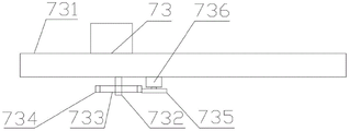
In the figure: 1. a first conveying mechanism; 11. a delivery stent; 12. a beam mechanism; 121. a main beam; 122. a first bearing; 123. a first gear; 124. a first power unit; 13. a longitudinal beam mechanism; 131. a third power unit; 132. a third guide rail; 14. a first adsorption mechanism; 141. adsorbing the stent; 142. a third slider; 143. a suction cup; 15. a placement mechanism; 151. placing a plate; 152. a compression plate; 153. a fourth power unit; 16. a first rack; 17. a first guide rail; 18. a first slider; 19. a drive mechanism; 191. a second guide rail; 192. a second slider; 193. a first drive bracket; 194. a second rack; 195. a second gear; 196. a second power unit; 2. a second conveying mechanism; 21. a main barrel; 22. an auxiliary cylinder; 23. a screw; 24. a fifth power plant; 25. a rod body; 251. a main rod; 252. a slave lever; 26. a sixth power plant; 27. heating a tube; 271. a heat insulation cylinder; 272. connecting sheets; 28. a fan; 281. an outer frame; 29. a first sensor; 3. a packaging mechanism; 31. a bag opening mechanism; 311. opening the bag main frame; 312. opening the bag and then placing the bag on a shelf; 313. sucking strips; 314. a seventh power plant; 315. a fourth guide rail; 316. a fourth slider; 32. a first conveying device; 33. a folding mechanism; 331. a first flap plate; 332. a second flap panel; 333. a folding roller; 334. an eighth power plant; 34. a seam mechanism; 341. a linking machine; 342. a seam support; 343. pressing a plate; 344. a blade; 345. a ninth power plant; 346. a tenth power plant; 35. a railing mechanism; 351. a breast board; 352. a rolling wheel; 36. a flat placing mechanism; 361. an eleventh power plant; 362. rolling wheels; 37. an expansion mechanism; 371. an injection pipe; 372. a control valve; 373. a twelfth power plant; 4. a detection mechanism; 41. a first detection device; 42. a second conveying device; 43. a weighing device; 44. a support mechanism; 441. a support frame; 442. a support wheel; 5. a sorting mechanism; 51. a sorting bracket; 52. a third conveying device; 53. a sorting device; 531. a second bearing; 532. a sorting tray; 533. a sorting shaft; 534. a first bevel gear; 535. a second taper tooth; 536. a thirteenth power plant; 54. a first driving device; 541. a third rack; 542. a second drive bracket; 543. a third gear; 544. a fourteenth power plant; 545. a third bearing; 55. material frame; 6. a shaping mechanism; 61. a fourth conveying device; 62. a main pressure device; 621. a main pressure plate; 622. a main pressing block; 623. a first vibrator; 624. a fifteenth power plant; 625. a first elastic device; 626. a slider; 627. a first support roller; 63. a side pressing device; 631. side pressing blocks; 632. a ball bearing; 633. a sixteenth power plant; 634. a second vibrator; 635. a step block; 636. connecting blocks; 637. a second elastic device; 638. a stepped groove; 64. a printing device; 65. a recovery device; 651. recovering the bracket; 652. a recovery wheel; 653. a seventeenth power plant; 66. an adsorption cylinder; 661. an adsorption hole; 662. an adsorption space; 67. a second driving device; 671. a cartridge holder; 672. an eighteenth power plant; 7. a stacking mechanism; 71. a first mobile device; 711. moving the support; 712. a movable shaft; 72. a gripper mechanism; 721. grabbing a frame; 722. a screw rod; 723. a moving block; 724. a grasping member; 725. a first connecting member; 726. a second connecting member; 727. a grab bar; 728. a twenty-third power plant; 73. a second mobile device; 731. a ball screw sliding table; 732. moving the column; 733. a fourth bearing; 734. a fourth rack; 735. a fourth gear; 736. a nineteenth power plant; 74. a stacking device; 741. stacking the supports; 742. stacking the plates; 743. a fifth rack; 744. a fifth gear; 745. a twentieth power plant; 746. a fifth slider; 747. a fifth guide rail; 75. a pushing device; 751. a push plate; 752. a twenty-first power device; 76. a lifting device; 761. a lifting frame; 762. a lifting rod; 763. and a twenty-second power device.
Detailed Description
The following describes a specific embodiment of the present embodiment with reference to the drawings.
FIG. 1 is a schematic structural diagram of the present invention. Fig. 2 is a left side view structural view of the first conveying mechanism of the present invention. Fig. 3 is an enlarged view of a point a in fig. 1. FIG. 4 is a structural diagram of the bag opener mechanism of the present invention. Fig. 5 is a left side view structural view of the creasing mechanism of the present invention. FIG. 6 is a structural view of the seaming mechanism of the present invention. Fig. 7 is an enlarged view of fig. 1 at B. Fig. 8 is an enlarged view of fig. 1 at C. FIG. 9 is a left side view of the side press device of the present invention. FIG. 10 is a schematic diagram of the recovery apparatus of the present invention. Fig. 11 is an enlarged view of fig. 1 at D. Fig. 12 is a block diagram of a first mobile device according to the present invention. Fig. 13 is a structural diagram of a second mobile device of the invention. Fig. 14 is a structural view of the inventive gripper mechanism. FIG. 15 is a view showing the construction of the stacking apparatus, the pushing apparatus and the elevating apparatus of the present invention. The invention discloses a full-automatic packaging and stacking production line, which is shown in combination with fig. 1, fig. 2, fig. 3, fig. 4, fig. 5, fig. 6, fig. 7, fig. 8, fig. 9, fig. 10, fig. 11, fig. 12, fig. 13, fig. 14 and fig. 15. The direction of X in the figure is the upper end of the structural schematic diagram of the invention, and the direction of Y in the figure is the right end of the structural schematic diagram of the invention.
The full-automatic packaging and stacking production line comprises a first conveying mechanism 1 for conveying packaging bags, a second conveying mechanism 2 for conveying materials, a packaging mechanism 3 for bagging the materials, a detection mechanism 4 for detecting the materials after bagging, a sorting mechanism 5 for screening unqualified materials, a shaping mechanism 6 for shaping the materials after bagging and a stacking mechanism 7 for stacking the materials after bagging on a tray. The packaging mechanism 3 is arranged at the discharge port of the second conveying mechanism 2. The wrapping bag is piled up and is placed in first conveying mechanism 1 one end, and the first conveying mechanism 1 other end is close to packagine machine and constructs 3. A detection mechanism 4, a sorting mechanism 5 and a shaping mechanism 6 are sequentially arranged between the packing mechanism 3 and the stacking mechanism 7.
The first conveying mechanism 1 comprises a conveying support 11, a beam mechanism 12 for driving the packaging bags to horizontally move, a longitudinal beam mechanism 13 for driving the packaging bags to vertically move, a first adsorption mechanism 14 for adsorbing the packaging bags, a placing mechanism 15 for placing the packaging bags and a driving mechanism 19 for driving the longitudinal beam mechanism 13 to move along the beam mechanism 12. The beam mechanism 12 is movably disposed on the transport rack 11. The side member mechanism 13 is provided on the cross member mechanism 12. The transport rack 11 is provided with a first rack 16 and a first guide rail 17 along the moving direction of the beam mechanism 12. A first slider 18 is slidably disposed on the first rail 17. The first slider 18 supports the beam mechanism 12. The beam mechanism 12 includes a main beam 121, first bearings 122 provided at both ends of the main beam 121, a first gear 123 engaging the first rack 16, and a first power unit 124 driving the first gear 123 to rotate. The first gear 123 rotates along the first bearing 122. The first gear 123 is connected to the drive end of the first power means 124. The driving mechanism 19 includes a second guide rail 191 provided on the main beam 121, a second slider 192 slidably provided on the second guide rail 191, a first driving bracket 193 moving along the main beam 121, a second rack 194 provided on the main beam 121, a second gear 195 engaging the second rack 194, and a second power unit 196 driving the second gear 195 to rotate. The first driving bracket 193 is provided on the second slider 192. The second power unit 196 is provided on the first driving bracket 193. The side member mechanism 13 includes a third power unit 131 that drives the first adsorption mechanism 14 and a third rail 132 provided on the first drive bracket 193. The third power unit 131 is provided on the first driving bracket 193. The first suction mechanism 14 is slidably disposed on the third rail 132. The first suction mechanism 14 includes a suction holder 141, a third slider 142 slidably disposed on the third rail 132, and a suction pad 143 for sucking the packaging bag. The third slider 142 is disposed at one end of the adsorption bracket 141. The suction pads 143 are horizontally arranged at the other end of the suction holder 141. The placing mechanism 15 includes a placing plate 151 for placing the packing bag, a pressing plate 152 for pressing the packing bag, and a fourth power unit 153 for pulling the pressing plate 152 close to the packing bag. The pressing plates 152 are swingably provided on both sides of the placing plate 151. The compression plate 152 is connected to the drive end of the fourth power means 153.
Preferably, the mounting plate 151 has an L-shape. Preferably, the fourth power device 153 is a cylinder. Preferably, the third power device 131 is a cylinder. Preferably, the second power means 196 is an electric motor. Preferably, the first power device 124 is an electric motor. The main beam 121 is slidably disposed on the transportation frame 11 in the front-rear direction. The upper end of the first slider 18 is connected to the main beam 121. The first bearings 122 are provided at front and rear ends of the main beam 121. The second rail 191 is provided on the main beam 121 in the front-rear direction. The second rack 194 is provided on the main beam 121 in the front-rear direction. The third guide rail 132 is provided on the first driving bracket 193 in the vertical direction. The third power unit 131 is vertically disposed on the first driving bracket 193. Suction cup 143 is connected to a gas source. The packing bags are vertically juxtaposed on the placing plate 151. The pressing plates 152 are swingably provided on the left and right sides of the placing plate 151. The fourth power means 153 are disposed at the left and right sides of the placing plate 151.
The first power device 124 is a motor, and the selection of the motor type belongs to the common knowledge. Those skilled in the art can select the motor based on the operation of the device, such as the 5IK120RGU-CF motor.
The second power unit 196 is an electric motor, and the selection of the type of the electric motor is well known. Those skilled in the art can select the motor based on the operation of the device, such as the 5IK120RGU-CF motor.
The third power device 131 is a cylinder, and the selection of the cylinder type belongs to the common knowledge. The person skilled in the art may choose the type of cylinder, for example, SC63 × 300, according to the working conditions of the device.
The fourth power device 153 is a cylinder, and the selection of the cylinder type belongs to the common knowledge. The person skilled in the art may choose the type of cylinder, for example, SC63 × 300, according to the working conditions of the device.
The packing bags are vertically juxtaposed on the placing plate 151, and the fourth power unit 153 drives the pressing plate 152 to press the packing bags. The first power device 124 drives the first gear 123 to rotate, and the first gear 123 moves along the first rack 16, so that the left and right movement of the packaging bag is completed. The second power unit 196 drives the second gear 195 to rotate, and the second gear 195 moves along the second rack 194, thereby completing the front and back movement of the packing bag. The third power device 131 drives the first adsorption mechanism 14 to move up and down to complete the up and down movement of the packaging bag. The suction cup 143 is communicated with the air source to complete the adsorption of the packaging bag, and the suction cup 143 is disconnected from the air source to put down the packaging bag.
The packaging bags are placed in parallel through the placing mechanism 15, the longitudinal beam mechanism 13, the cross beam mechanism 12 and the driving mechanism 19 complete the movement of the packaging bags, and the first adsorption mechanism 14 completes the adsorption of the packaging bags, so that the first conveying mechanism 1 improves the efficiency of conveying the packaging bags.
The second conveying mechanism 2 comprises a main cylinder 21 for storing materials, an auxiliary cylinder 22 communicated with the main cylinder 21 in parallel, a screw 23 for conveying the materials, a fifth power device 24 for driving the screw 23 to rotate, a rod body 25 for scattering the materials, a sixth power device 26 for driving the rod body 25 to rotate, a heating pipe 27 for heating the materials, a fan 28 for cooling the materials and a first sensor 29 for detecting the flow rate of the materials. The inlet of the auxiliary cylinder 22 is communicated with the outlet of the main cylinder 21. A screw 23 is rotatably provided in the sub-cylinder 22. The screw 23 is connected with the driving end of a fifth power device 24. A heating pipe 27 is disposed around the sub-cartridge 22. The heating tube 27 is provided with a connecting piece 272. The heating pipe 27 is wrapped with a heat insulation cylinder 271. An outer frame 281 is provided around the heat insulating cylinder 271. The connecting pieces 272 connect the sub-cartridge 22 and the outer frame 281, respectively. The blower 28 is provided on the outer frame 281. The lever body 25 includes a main lever 251 rotatably disposed in the main cylinder 21 and a sub lever 252 juxtaposed around the main lever 251. The slave bar 252 has a first tooth profile arranged in parallel. The main rod 251 is connected to the driving end of the sixth power device 26. A first sensor 29 is provided between the inlet of the secondary cartridge 22 and the outlet of the primary cartridge 21.
Preferably, the first sensor 29 is a flow meter. Preferably, the sixth power device 26 is an electric motor. Preferably, the fifth power device 24 is an electric motor. The sub-tubes 22 are arranged in parallel at the lower end of the main tube 21 in an inclined manner in the vertical direction. The upper end of the sub-cylinder 22 communicates with the lower end of the main cylinder 21. The lower end of the secondary drum 22 discharges the material. A heating pipe 27 is disposed around the outer surface of the sub-cartridge 22. The connecting piece 272 is juxtaposed on the outer surface of the heating tube 27. An outer frame 281 is disposed around the outer surface of the heat insulating cylinder 271. The driving end of the fifth power device 24 is connected with the upper end of the screw 23. The first sensor 29 is disposed between the upper end of the sub-drum 22 and the lower end of the main drum 21.
The main lever 251 is rotatably provided in the main cylinder 21. Secondary rods 252 are juxtaposed around the outer surface of primary rod 251. A first tooth form is formed in parallel from the outer surface of the rod 252. A sixth power unit 26 is provided at the upper end of the main drum 21. The driving end of the sixth power device 26 is connected with the upper end of the main rod 251.
The fifth power device 24 is a motor, and the selection of the motor type belongs to the common knowledge. Those skilled in the art can select the motor based on the operation of the device, such as the 5IK120RGU-CF motor.
The sixth power device 26 is a motor, and the selection of the motor type belongs to the common knowledge. Those skilled in the art can select the motor according to the working condition of the device, for example, the motor with the model number of 5IK120RGU-CF can be selected.
The first sensor 29 is a flow meter and the choice of the type of flow meter is well known. The flow meter, model JCK-GTK/C, can be selected by those skilled in the art according to the operation of the device.
The selection of the type of fan 28 is well known in the art. The skilled person can select the fan according to the working condition of the device, for example, the fan with model number HY-380 can be selected.
The material enters the main barrel 21 from the upper end of the main barrel 21, and the sixth power device 26 drives the rod body 25 to rotate so as to break up the material. The material enters the secondary barrel 22 through the first sensor 29, and the flow rate of the material is calculated. The fifth power device 24 drives the screw 23 to rotate, and the screw 23 pushes the materials to move along the secondary barrel 22 and be discharged from the outlet of the secondary barrel 22.
The material can be scattered through the rod body 25, and the blockage of the second conveying mechanism 2 caused by the material is avoided. Through the flow of the first sensor 29 material, the material conveying amount can be adjusted by adjusting the rotating speed of the screw 23, and different production requirements are met. When the screw 23 stops rotating, the screw 23 can seal the inner part of the auxiliary barrel 22, so that the outflow of materials is avoided, and the accuracy of the material conveying capacity is ensured. The heating of material can be accomplished through heating pipe 27, and the cooling of material can be accomplished through fan 28 for the packing pile up neatly of different materials can be satisfied to full-automatic packing pile up neatly production line.
The packaging mechanism 3 includes a bag opening mechanism 31 for opening the opening of the packaging bag, a first conveying device 32 for moving the packaged material, a folding mechanism 33 for folding the opening of the packaging bag, a seam mechanism 34 for sewing the opening of the packaging bag, a railing mechanism 35 for rolling and supporting the packaged material, a flat placing mechanism 36 for pushing and pouring the packaged material, and an expanding mechanism 37 for expanding the packaging bag. The bag opening mechanism 31, the folding mechanism 33, the sewing mechanism 34 and the placing mechanism 36 are arranged on the first conveying device 32 along the moving direction of the bagged materials. The railing mechanism 35 is arranged between the bag opening mechanism 31, the folding mechanism 33, the sewing mechanism 34 and the flat-placing mechanism 36 at intervals. The expanding mechanism 37 is movably provided on the bag opening mechanism 31. The bag opening mechanism 31 includes a bag opening main frame 311, a bag opening sub frame 312 provided to the bag opening main frame 311 so as to be relatively movable, a suction bar 313 for sucking an opening position of the packaging bag, a seventh power unit 314 for driving the suction bar 313 to move, a fourth guide rail 315 provided to the bag opening main frame 311, and a fourth slider 316 provided to the fourth guide rail 315 so as to be slidable. The bag opening slave carrier 312 is disposed on the fourth slider 316. The suction strip 313 is provided on the open pocket slave shelf 312. The driving end of the seventh power device 314 is connected with the bag opening slave frame 312. The folding mechanism 33 includes a first folding plate 331 for folding, a second folding plate 332 disposed in the first folding plate 331, a folding roller 333 for pressing the folding position of the packaging bag, and an eighth power unit 334 for driving the folding roller 333 to approach the packaging bag. Both ends of the first flap 331 and both ends of the second flap 332 are respectively extended to be outwardly expanded. The creasing roller 333 is rotatably disposed at a driving end of the eighth power unit 334. The folding rollers 333 are located on both sides of the folding position of the packing bag. The sewing mechanism 34 includes a sewing bracket 342, a sewing machine 341 for sewing the packaging bag, a pressing plate 343 for pressing the thread, a blade 344 for cutting the thread, a ninth power unit 345 for driving the pressing plate 343 to approach each other, and a tenth power unit 346 for driving the blade 344 to approach the thread. The pressing plates 343 are arranged on the slit brackets 342 in a staggered swinging manner. The blade 344 is connected to the driving end of a tenth power means 346. A ninth power means 345 is disposed between pressure plates 343. The railing mechanism 35 includes a balustrade 351 provided on the first conveyor 32 in the moving direction of the bagged material and a roller 352 for rolling and supporting the bagged material. The rolling wheels 352 are rotatably provided in parallel on the balustrade 351. The flat-laying mechanism 36 includes a roller 362 for rolling the bagged material and an eleventh motive device 361 for driving the roller 362 adjacent to the bagged material. A stitching wheel 362 is rotatably provided at the drive end of the eleventh power unit 361. The expanding mechanism 37 includes an injection tube 371 for injecting gas, and a twelfth motive power device 373 for driving the injection tube 371 to approach the packaging bag by opening and closing a control valve 372 of the injection tube 371. One end of the injection tube 371 is connected with an air source, and the other end of the injection tube 371 faces the inside of the packaging bag.
Preferably, the twelfth motive device 373 is a cylinder. Preferably, the eleventh motive device 361 is a cylinder. Preferably, the tenth power unit 346 is a cylinder. Preferably, the ninth power device 345 is a cylinder. Preferably, the eighth power means 334 is a cylinder. Preferably, the seventh power device 314 is a cylinder. Preferably, the first conveyor 32 is a conveyor.
The first conveyor 32 is disposed in the left-right direction. The fourth guide rail 315 is provided on the bag opening main frame 311 in the front-rear direction. The lower end of the fourth slider 316 is slidably connected to the fourth guide rail 315. The upper end of the fourth sliding block 316 is connected with the suction strip 313. The suction strip 313 is connected to a gas source. The twelfth power device 373 is disposed on the bag opening sub-frame 312. A control valve 372 is provided at the drive end of the twelfth power means 373. The upper end of the first flap 331 is bent toward the second flap 332. The upper end of the second flap panel 332 is disposed at the bending position of the first flap panel 331. The creasing roller 333 is oppositely disposed at a right end position of the second creasing plate 332. One end of the pressure plate 343 grips the suture. The other end of the pressing plate 343 is connected to a ninth power unit 345. The balustrades 351 are provided on the front and rear sides of the first conveyor 32 in the left-right direction.
The first conveyor 32 is a conveyor, and the selection of the type of conveyor is well known. Those skilled in the art can select the type of conveyor LSD-10063, for example, according to the operation of the device.
The seventh power unit 314 is a cylinder, and the selection of the cylinder type belongs to the common knowledge. The person skilled in the art may choose the type of cylinder, for example, SC63 × 200, according to the working conditions of the device.
The eighth power device 334 is a cylinder, and the selection of the cylinder type belongs to the common knowledge. The skilled person will be able to select the type of cylinder, for example, SC63 × 75, according to the operation of the device.
The ninth power plant 345 is a cylinder, and the selection of the cylinder type belongs to the common knowledge. The skilled person will be able to select the type of cylinder, for example, SC63 × 75, according to the operation of the device.
The tenth power means 346 is a cylinder, the choice of cylinder type being common knowledge. The person skilled in the art may choose the type of cylinder, for example, SC63 × 50, according to the working conditions of the device.
The eleventh power means 361 is a cylinder, and the selection of the cylinder type is common knowledge. The person skilled in the art may choose the type of cylinder, for example, SC63 × 200, according to the working conditions of the device.
The twelfth power device 373 is a cylinder, and the selection of the cylinder type belongs to the common knowledge. The skilled person will be able to select the type of cylinder, for example, SC63 × 75, according to the operation of the device.
The seventh power device 314 drives the suction strip 313 to be close to the packaging bag, and the suction strip 313 sucks the opening of the packaging bag to open the packaging bag. The twelfth power device 373 drives the injection tube 371 to approach the inside of the packing bag, the control valve 372 opens the injection tube 371, and the gas enters the packing bag to expand the inside of the packing bag. The first conveyor 32 drives the bagged materials to move along the side plates 351, and the rolling wheels 352 roll and support the bagged materials. The opening of the packing bag is positioned between the first flap panel 331 and the second flap panel 332 to bend the opening of the packing bag. The eighth power device 334 drives the folding roller 333 to rotate, and the folding roller 333 rolls and presses the folding position of the packaging bag. The seaming machine 341 seams the bag at the fold, the ninth power device 345 drives the pressing plates 343 to approach each other, the pressing plates 343 clamp the suture, and the tenth power device 346 drives the blade 344 to cut the suture. An eleventh power device 361 drives the rolling wheel 362 to approach the bagged materials to push the bagged materials to be poured.
The packaging bag can be opened through the bag opening mechanism 31, and the expansion mechanism 37 can expand the packaging bag to facilitate the bagging of materials. The bag can be sewn by the folding mechanism 33 and the sewing mechanism 34. Can restrict the back material of bagging-off through railing mechanism 35, conveniently carry out the bagging-off of material and the book mouthful of sewing up of wrapping bag. The bagged materials are pushed to be horizontally placed through the horizontal placing mechanism 36, so that the subsequent shaping process is facilitated.
The detection mechanism 4 comprises a first detection device 41 for detecting the metal content of the bagged material, a second conveying device 42 for moving the bagged material, a weighing device 43 for weighing the bagged material and a supporting mechanism 44 for rolling and supporting the bagged material. The first detection device 41 is arranged on the second transport device 42. The weighing device 43 and the support mechanism 44 are disposed within the second conveyor 42. The support mechanism 44 includes a support frame 441 provided on the weighing device 43 and a support wheel 442 that rollingly supports the belt of the second conveyor 42. The supporting wheels 442 are rotatably disposed in parallel on the supporting frame 441. The bagged material is placed on the belt of the second conveyor 42.
Preferably, the second conveyor 42 is a conveyor. Preferably, the first detecting device 41 is a metal detector. Preferably, the weighing device 43 is an electronic scale. The second conveying device 42 drives the bagged materials to move close to the first detection device 41, the first detection device 41 detects whether metal pieces exist in the bagged materials, and if the metal pieces are detected, the bagged materials are unqualified bagged materials. The second conveying device 42 drives the bagged materials to move close to the weighing device 43, the weighing device 43 weighs the bagged materials, and if the weighed weight has deviation, the bagged materials are unqualified bagged materials.
The second conveyor 42 is a conveyor, and the selection of the type of conveyor is well known. Those skilled in the art can select the type of conveyor LSD-10063, for example, according to the operation of the device.
The first detecting means 41 is a metal detector, and the type of the metal detector is selected according to the common knowledge. The person skilled in the art can choose the type of metal detector FT-R970, for example, according to the working conditions of the device.
The weighing device 43 is an electronic scale, and the selection of the type of the electronic scale is common knowledge. The person skilled in the art can choose the type JH-his electronic scale, for example, depending on the operation of the device.
The sorting mechanism 5 includes a sorting support 51, a third conveyor 52 for moving the defective material, a sorting device 53 for moving the bagged material, a first driving device 54 for driving the sorting device 53 to rotate, and a material frame 55 for recovering the defective material. The third conveyor 52 is disposed between the sorting support 51 and the material frame 55. The sorting device 53 is rotatably arranged in parallel on the sorting support 51. The sorting device 53 includes a second bearing 531 provided on the sorting support 51, a sorting disk 532 rotatably provided in the second bearing 531, a sorting shaft 533 rotatably provided in the sorting disk 532 in parallel, a first bevel gear 534 coaxially provided at one end of the sorting shaft 533, a second bevel gear 535 rotatably provided in the sorting disk 532, and a thirteenth power unit 536 for driving the second bevel gear 535. The first and second conical teeth 534, 535 intermesh. A thirteenth motive device 536 is disposed within sorting tray 532. The first driving device 54 includes a third rack 541 provided around the sorting tray 532, a second driving bracket 542 provided in the sorting bracket 51, a third gear 543 rotatably provided in the second driving bracket 542, a fourteenth power device 544 for driving the third gear 543 to rotate, and a third bearing 545 for restricting the third gear 543. The third gear 543 is engaged with the third rack 541. A fourteenth power device 544 is provided on second drive bracket 542. Third bearings 545 are provided in second drive carrier 542 on both sides of third gear 543. The third bearing 545 is a planar bearing.
Preferably, the fourteenth power device 544 is an electric motor. Preferably, the thirteenth power device 536 is an electric motor. The sorting disk 532 is rotatably disposed at an inner race of the second bearing 531. The outer ring of the second bearing 531 is connected to the sorting holder 51. A third rack 541 is disposed around the outer surface of the sorting disk 532. The second driving bracket 542 is disposed at the lower end of the sorting bracket 51. Third bearings 545 are provided at upper and lower ends of the third gear 543 in the second driving bracket 542. The third conveyor 52 communicates with the sorting support 51.
The thirteenth power device 536 drives the second bevel gear 535 to rotate, the second bevel gear 535 drives the first bevel gear 534 and the sorting shaft 533 to rotate, and the sorting shaft 533 drives the bagged materials to move. The fourteenth power device 544 drives the third gear 543 to rotate, the third gear 543 drives the sorting device 53 to rotate by a certain angle, the moving direction of the unqualified bagged materials is changed, and the unqualified bagged materials move into the material frame 55 through the third conveying device 52.
The thirteenth power plant 536 is a motor, and the selection of the motor type is common knowledge. Those skilled in the art can select the motor based on the operation of the device, such as the 5IK120RGU-CF motor.
The fourteenth power device 544 is a motor, and the selection of the motor type belongs to the common knowledge. Those skilled in the art can select the motor based on the operation of the device, such as the 5IK120RGU-CF motor.
Unqualified materials can be detected by the detection mechanism 4. The unqualified materials can be recycled through the sorting mechanism 5 under the condition that the working heart rate of the full-automatic packaging and stacking production line is not influenced.
The shaping mechanism 6 includes a fourth conveying device 61 for moving the bagged material, a main pressing device 62 for pressing the bagged material flatly, a side pressing device 63 for pressing the bagged material laterally, a printing device 64 for printing labels, a recovery device 65 for recovering waste labels, an adsorption cylinder 66 for adsorbing the labels, and a second driving device 67 for driving the adsorption cylinder 66 to move. The main pressing device 62 comprises a main pressing plate 621 arranged on two sides of the fourth conveying device 61 in a parallel swinging mode, a main pressing block 622 for pressing flat packed materials, a first vibrator 623 for driving the main pressing block 622 to vibrate, a fifteenth power device 624 for pushing the main pressing plate 621, a first elastic device 625 for propping against the main pressing plate 621, a sliding piece 626 for slidably supporting the main pressing plate 621, and a first supporting roller 627 for rolling and supporting the main pressing plate 621. The main pressure plate 621 is connected with the main pressure block 622 in a swinging manner. The first vibrator 623 is disposed on the main pressing block 622. The first elastic means 625 are arranged side by side on both sides of the fourth conveyor 61. The sliders 626 are slidably disposed at both sides of the fourth conveying device 61. The slider 626 is connected to the driving end of the fifteenth power device 624. The first support roller 627 is rotatably provided on the slider 626. The lateral pressing device 63 includes a lateral pressing block 631 for laterally pressing the bagged material, balls 632 for rolling and supporting the lateral pressing block 631, a sixteenth power device 633 for driving the lateral pressing block 631 to move, a second vibrator 634 for vibrating the lateral pressing block 631, a stepped block 635 provided on the lateral pressing block 631, a connecting block 636 provided at a driving end of the sixteenth power device 633, and a second elastic device 637 for elastically supporting the stepped block 635. The balls 632 are rotatably arranged in parallel at one end of the side press 631 adjacent to the fourth conveyor 61. The second vibrator 634 is provided on the side pressing block 631. Stepped groove 638 is provided on connecting block 636. The second elastic device 637 is disposed in the stepped groove 638. The step block 635 is fitted into the step groove 638. The recovery device 65 includes a recovery bracket 651, a recovery wheel 652 rotatably provided in parallel to the recovery bracket 651, and a seventeenth power unit 653 for driving the recovery wheel 652 to rotate. The label waste is wound around the recovery wheel 652. A seventeenth power unit 653 is provided on the recovery bracket 651. A plurality of suction holes 661 are formed around the suction cylinder 66. A plurality of adsorption spaces 662 are formed in the adsorption cylinder 66. The adsorption holes 661 communicate with the corresponding adsorption spaces 662. The adsorption space 662 is connected to a gas source through a connector. The second driving device 67 includes a cylinder holder 671 and an eighteenth power device 672 that drives the cylinder holder 671 to move. The adsorption cylinder 66 is rotatably provided on the cylinder holder 671. The cartridge holder 671 is connected to the driving end of an eighteenth power means 672.
Preferably, the eighteenth power means 672 is a cylinder. Preferably, the seventeenth power device 653 is an electric motor. Preferably, the sixteenth power means 633 is a cylinder. Preferably, the fifteenth power device 624 is a cylinder. Preferably, the fourth conveying device 61 is a conveyor. The upper end of the main pressure plate 621 is connected with a main pressure block 622 in a swinging way. The lower end of the main pressing plate 621 is swing-connected to the fourth conveying device 61. A fifteenth power device 624 is provided on the fourth conveyor 61 in the left-right direction. The sliders 626 are provided on both sides of the fourth conveying device 61 to slide in the vertical direction. The first supporting roller 627 is rotatably provided at the upper end of the slider 626. The balls 632 are rotatably disposed in parallel at the lower end of the side pressure block 631. The adsorption hole 661 is opened around the outer surface of the adsorption cylinder 66.
The first elastic device 625 pushes the main pressing plate 621, and the first vibrator 623 drives the main pressing block 622 to vibrate, so as to flatten the bagged materials in the up-down direction. The sixteenth power device 633 drives the side pressing block 631 to be close to the front side and the rear side of the bagged material, and the second vibrator 634 drives the side pressing block 631 to vibrate to flatten the front side and the rear side of the bagged material. The fifteenth power device 624 drives the slider 626 to approach the main pressing plate 621, and the first supporting roller 627 rollingly supports the main pressing plate 621. The main pressing block 622 moves upwards, and the fourth conveying device 61 drives the bagged materials to move. Printing device 64 prints the label, and eighteenth power device 672 upwards drives and adsorbs a section of thick bamboo 66 and is close to the label, adsorbs hole 661 adsorption label, and eighteenth power device 672 downwards drives and adsorbs a section of thick bamboo 66 and is close to bagging-off back material adsorption hole 661 and stops adsorbing the label, and the label laminating is on the material after the bagging-off. The seventeenth power means 653 drives the recovery wheel 652 to rotate the recovered tag waste.
The fourth conveyor 61 is a conveyor, the selection of which conveyor type is common knowledge. The person skilled in the art may choose the operation of the device, for example a conveyor of the type SC63 × 75.
The fifteenth power device 624 is a cylinder, and the selection of the cylinder type belongs to the common knowledge. The person skilled in the art may choose the type of cylinder, for example, SC63 × 100, according to the working conditions of the device.
The sixteenth power device 633 is a cylinder, and the selection of the type of the cylinder belongs to the common knowledge. The person skilled in the art may choose the type of cylinder, for example, SC63 × 100, according to the working conditions of the device.
The seventeenth power device 653 is a motor, and the selection of the type of the motor belongs to the common knowledge. Those skilled in the art can select the motor based on the operation of the device, such as the 5IK120RGU-CF motor.
The eighteenth power device 672 is a cylinder, and the selection of the cylinder type belongs to the common knowledge. The person skilled in the art may choose the type of cylinder, for example, SC63 × 200, according to the working conditions of the device.
The bagged materials are flattened in the up-and-down direction through the main pressing device 62, the flattening of the side faces of the bagged materials is completed through the side pressing device 63, the stable attaching of the labels is completed through the adsorption cylinder 66, the stacking of the follow-up materials is facilitated, and the stacking efficiency is improved.
The stacking mechanism 7 comprises a first moving device 71 for moving bagged materials, a gripper mechanism 72 for gripping the bagged materials, a second moving device 73 for moving the bagged materials, a stacking device 74 for stacking and placing the bagged materials, a pushing device 75 for pressing the stacked materials, and a lifting device 76 for lifting the stacking device 74. The stacking device 74 is movably disposed within the elevator device 76. The first moving device 71 includes a moving frame 711 and a moving shaft 712 rotatably provided in parallel on the moving frame 711. There is a space between adjacent moving axes 712. The gripping mechanism 72 comprises a second connecting member 726, a first connecting member 725, a gripping frame 721, a screw rod 722 rotatably arranged in the gripping frame 721, a moving block 723 movably arranged on the screw rod 722, a gripping member 724 for gripping bagged materials, and a twenty-third power device 728 for driving the screw rod 722 to rotate. The first link 725 is relatively swingably provided on the grab frame 721. The second link 726 is provided on the moving block 723 to swing relatively. The grasping member 724 is respectively connected with one end of the second connecting member 726 far away from the moving block 723 and one end of the first connecting member 725 far away from the grasping frame 721 in a swinging manner. The grabbing pieces 724 are provided with grabbing rods 727 in parallel. There is a space between adjacent grab bars 727. A twenty-third power plant 728 is disposed within the grab frame 721. The second moving device 73 includes a ball screw sliding table 731 for driving the bagged material to move horizontally, a moving column 732 passing through the gripping frame 721, a fourth bearing 733 rotatably disposed on the moving column 732, a fourth rack 734 disposed around the fourth bearing 733, a fourth gear 735 meshing with the fourth rack 734, and a nineteenth power device 736 for driving the fourth gear 735 to rotate. Ball screw slip table 731 is crisscross setting. A moving column 732 and a nineteenth power unit 736 are provided at a moving end of the ball screw sliding table 731. The fourth bearing 733 is connected to the gripper 721. The stacking device 74 includes a stacking bracket 741, a stacking plate 742 disposed on the stacking bracket 741 in a relatively sliding manner, a fifth rack 743 disposed on one side of the stacking plate 742, a fifth gear 744 meshing with the adjacent fifth rack 743, a twentieth power device 745 driving the fifth gear 744 to rotate, a fifth slider 746 disposed on the other side of the stacking plate 742, and a fifth guide 747 disposed on the stacking bracket 741. The twentieth power unit 745 is provided on the stacking bracket 741. The fifth slider 746 is slidably disposed on the fifth rail 747. The pushing device 75 comprises a pushing plate 751 for pressing corners of the stacked materials and a twenty-first power device 752 for pushing the pushing plate 751 to move. The driving end of the twenty-first power device 752 is connected to a pushing plate 751. The lifting device 76 includes a lifting frame 761, a lifting lever 762 cross-connected to each other, and a twenty-second power device 763 for pushing the lifting lever 762. The stacking support 741 is movably arranged on the lifting frame 761. One end of the lifting rod 762 is movably connected with the stacking bracket 741. The other end of the lifting rod 762 is movably connected with the bottom of the lifting frame 761. The lifting lever 762 is connected to the drive end of the twenty-second power device 763.
Preferably, the twenty-second power device 763 is a cylinder. Preferably, the twenty-first power device 752 is a cylinder. Preferably, the twentieth power means 745 is a motor. Preferably, the nineteenth power device 736 is an electric motor. Preferably, the twenty-third power device 728 is an electric motor. Preferably, the ball screw sliding tables 731 are two sets. The moving shaft 712 is rotatably provided at the upper end of the moving bracket 711 in the front-rear direction. The screw 722 is rotatably provided in the holder 721 in the vertical direction. The upper end of the first connecting piece 725 is connected with the grab 721 in a swinging way. The lower end of the first link 725 is pivotally connected to the catch 724. The upper end of the second connecting member 726 is connected with a moving block 723 in a swinging manner. The lower end of the second link 726 is pivotally connected to the catch 724. The inner race of the fourth bearing 733 is connected to the moving post 732. The outer ring of the fourth bearing 733 is connected with the grab frame 721. The fourth rack 734 is disposed around an outer ring of the fourth bearing 733. A push plate 751 is disposed around the palletized material. The upper end of the twenty-second power device 763 is provided with a twenty-second power device 763 driving end. The twenty-second power device 763 is arranged on the lifting frame 761.
The first moving device 71 completes the movement of the bagged materials, the twenty-third power device 728 drives the lead screw 722 to rotate, and the moving block 723 moves upwards to pull the grabbing pieces 724 to get close to each other to grab the bagged materials. The nineteenth power device 736 drives the fourth gear 735 to rotate, and the fourth gear 735 drives the fourth bearing 733, the gripper mechanism 72 and the bagged material to rotate. The left and right movement and the front and back movement of the bagged materials are completed through the ball screw sliding table 731. After the bagged materials are stacked on the stacking plate 742, the twentieth power device 745 drives the fifth gear 744 to rotate, the fifth gear 744 drives the stacking plate 742 to move away from each other, and the bagged materials fall onto the tray under the pushing of the stacking bracket 741. The twenty-first power device 752 drives the push plate 751 to compress the palletized materials. The twenty-second power device 763 pushes the lifting rods 762 to approach each other, and the height of the stacking device 74 is adjusted, so that stacked materials with different heights can be stacked.
Grabbing and placing of bagged materials can be completed through the gripper mechanism 72, the second moving device 73 completes moving of the bagged materials, the stacking device 74 and the lifting device 76 complete stacking of the stacked materials, and the pushing device 75 pushes the stacked materials to stack the stacked materials in order. The stacking mechanism 7 can move stacked materials without a manipulator, and use cost is reduced. The stacking mechanism 7 distributes all steps of stacking the stacked materials to different devices to complete the stacking, so that the stacking time of the stacked materials is shortened, and the efficiency is improved.
The twenty-third power unit 728 is a motor, and the selection of the type of the motor is common knowledge. Those skilled in the art can select the motor based on the operation of the device, such as the 5IK120RGU-CF motor.
The nineteenth power plant 736 is a motor, and the selection of the motor type belongs to the common knowledge. Those skilled in the art can select the motor based on the operation of the device, such as the 5IK120RGU-CF motor.
The twentieth power unit 745 is a motor, and the selection of the motor type is well known. Those skilled in the art can select the motor based on the operation of the device, such as the 5IK120RGU-CF motor.
The twenty-first power device 752 is a cylinder, and the selection of the cylinder type is common knowledge. The person skilled in the art may choose the type of cylinder, for example, SC63 × 200, according to the working conditions of the device.
The twenty-second power device 763 is a cylinder, and the selection of the cylinder type belongs to the common knowledge. The person skilled in the art may choose the type of cylinder, for example, SC63 × 200, according to the working conditions of the device.
In the description of the embodiments of the present invention, it should be further noted that unless otherwise explicitly stated or limited, the terms "disposed" and "connected" should be interpreted broadly, and may be, for example, fixedly connected, detachably connected, or integrally connected; can be mechanically or electrically connected; they may be connected directly or indirectly through intervening media, or they may be interconnected between two elements. The specific meanings of the above terms in the present invention can be understood in specific cases to those skilled in the art.
The foregoing description is illustrative of the present invention and is not to be construed as limiting thereof, the scope of the invention being defined by the appended claims, which may be modified in any manner without departing from the basic structure thereof.
Claims (7)
1. The utility model provides a full-automatic packing pile up neatly production line which characterized in that: the automatic packaging machine comprises a first conveying mechanism (1) for conveying packaging bags, a second conveying mechanism (2) for conveying materials, a packaging mechanism (3) for bagging the materials, a detection mechanism (4) for detecting the packaged materials, a sorting mechanism (5) for screening unqualified materials, a shaping mechanism (6) for shaping the packaged materials and a stacking mechanism (7) for stacking the packaged materials on a tray; the packaging mechanism (3) is arranged at the discharge hole of the second conveying mechanism (2); the packaging bags are stacked at one end of the first conveying mechanism (1), and the other end of the first conveying mechanism (1) is close to the packaging mechanism (3); the detection mechanism (4), the sorting mechanism (5) and the shaping mechanism (6) are sequentially arranged between the packaging mechanism (3) and the stacking mechanism (7);
the shaping mechanism (6) comprises a fourth conveying device (61) for moving the bagged materials, a main pressing device (62) for flattening the bagged materials, a lateral pressing device (63) for laterally pressing the bagged materials, a printing device (64) for printing labels, a recovery device (65) for recovering label waste, an adsorption cylinder (66) for adsorbing the labels and a second driving device (67) for driving the adsorption cylinder (66) to move; the main pressing device (62) comprises main pressing plates (621) which are arranged on two sides of the fourth conveying device (61) in a parallel swinging mode, a main pressing block (622) for pressing the bagged materials flatly, a first vibrator (623) for driving the main pressing block (622) to vibrate, a fifteenth power device (624) for pushing the main pressing plate (621), a first elastic device (625) for propping against the main pressing plate (621), a sliding piece (626) for supporting the main pressing plate (621) in a sliding mode, and a first supporting roller (627) for supporting the main pressing plate (621) in a rolling mode; the main pressing plate (621) is connected with the main pressing block (622) in a swinging mode; the first vibrator (623) is arranged on the main pressing block (622); the first elastic devices (625) are arranged on two sides of the fourth conveying device (61) in parallel; the slide pieces (626) are arranged on two sides of the fourth conveying device (61) in a sliding mode; the slider (626) is connected with the driving end of the fifteenth power device (624); the first supporting roller (627) is rotatably arranged on the slider (626); the side pressing device (63) comprises a side pressing block (631) for pressing the bagged materials in a side pressing mode, a ball (632) for supporting the side pressing block (631) in a rolling mode, a sixteenth power device (633) for driving the side pressing block (631) to move, a second vibrator (634) for driving the side pressing block (631) to vibrate, a step block (635) arranged on the side pressing block (631), a connecting block (636) arranged at the driving end of the sixteenth power device (633) and a second elastic device (637) for elastically supporting the step block (635); the balls (632) are arranged on one end of the side pressing block (631) close to the fourth conveying device (61) in a parallel rotating mode; the second vibrator (634) is disposed on the side pressing block (631); a stepped groove (638) is formed in the connecting block (636); the second elastic device (637) is arranged in the stepped groove (638); the step block (635) is embedded into the step groove (638); the recovery device (65) comprises a recovery bracket (651), a recovery wheel (652) which is arranged on the recovery bracket (651) in a parallel rotating manner, and a seventeenth power device (653) which drives the recovery wheel (652) to rotate; the label waste is wound on the recycling wheel (652); the seventeenth power device (653) is arranged on the recovery bracket (651); a plurality of adsorption holes (661) are arranged around the adsorption cylinder (66); a plurality of adsorption spaces (662) are formed in the adsorption cylinder (66); the adsorption holes (661) are communicated with the corresponding adsorption spaces (662); the adsorption space (662) is connected with a gas source through a connector; the second driving device (67) comprises a cylinder bracket (671) and an eighteenth power device (672) for driving the cylinder bracket (671) to move; the adsorption cylinder (66) is rotatably arranged on the cylinder bracket (671); the cylinder bracket (671) is connected with the driving end of the eighteenth power device (672).
2. The full-automatic packaging and palletizing production line as claimed in claim 1, wherein: the first conveying mechanism (1) comprises a conveying support (11), a beam mechanism (12) for driving the packaging bags to move horizontally, a longitudinal beam mechanism (13) for driving the packaging bags to move vertically, a first adsorption mechanism (14) for adsorbing the packaging bags, a placing mechanism (15) for placing the packaging bags and a driving mechanism (19) for driving the longitudinal beam mechanism (13) to move along the beam mechanism (12); the beam mechanism (12) is movably arranged on the conveying bracket (11); the longitudinal beam mechanism (13) is arranged on the cross beam mechanism (12); a first rack (16) and a first guide rail (17) are respectively arranged on the conveying bracket (11) along the moving direction of the beam mechanism (12); a first sliding block (18) is arranged on the first guide rail (17) in a sliding manner; the first slider (18) supporting the beam mechanism (12); the beam mechanism (12) comprises a main beam (121), first bearings (122) arranged at two ends of the main beam (121), a first gear (123) meshed with the first rack (16) and a first power device (124) driving the first gear (123) to rotate; -the first gear wheel (123) rotates within the first bearing (122); the first gear (123) is connected with the driving end of the first power device (124); the driving mechanism (19) comprises a second guide rail (191) arranged on the main beam (121), a second sliding block (192) arranged on the second guide rail (191) in a sliding manner, a first driving bracket (193) moving along the main beam (121), a second rack (194) arranged on the main beam (121), a second gear (195) engaged with the second rack (194) and a second power device (196) driving the second gear (195) to rotate; the first drive bracket (193) is disposed on the second slider (192); the second power device (196) is arranged on the first driving bracket (193); the longitudinal beam mechanism (13) comprises a third power device (131) for driving the first adsorption mechanism (14) and a third guide rail (132) arranged on the first driving bracket (193); the third power device (131) is arranged on the first driving bracket (193); the first adsorption mechanism (14) is arranged on the third guide rail (132) in a sliding mode; the first adsorption mechanism (14) comprises an adsorption bracket (141), a third slide block (142) arranged on the third guide rail (132) in a sliding manner, and a sucker (143) for adsorbing the packaging bag; the third sliding block (142) is arranged at one end of the adsorption bracket (141); the suckers (143) are horizontally arranged at the other end of the adsorption bracket (141) in parallel; the placing mechanism (15) comprises a placing plate (151) for placing the packaging bag, a pressing plate (152) for pressing the packaging bag and a fourth power device (153) for pulling the pressing plate (152) to be close to the packaging bag; the pressing plates (152) are arranged on two sides of the placing plate (151) in a swinging mode; the pressing plate (152) is connected with the driving end of the fourth power device (153).
3. The full-automatic packaging and palletizing production line as claimed in claim 1, wherein: the second conveying mechanism (2) comprises a main barrel (21) for storing the materials, an auxiliary barrel (22) which is communicated with the main barrel (21) in parallel, a screw (23) for conveying the materials, a fifth power device (24) for driving the screw (23) to rotate, a rod body (25) for scattering the materials, a sixth power device (26) for driving the rod body (25) to rotate, a heating pipe (27) for heating the materials, a fan (28) for cooling the materials and a first sensor (29) for detecting the flow rate of the materials; the inlet of the auxiliary cylinder (22) is communicated with the outlet of the main cylinder (21); the screw rod (23) is rotatably arranged in the auxiliary barrel (22); the screw rod (23) is connected with the driving end of the fifth power device (24); the heating pipe (27) is arranged around the auxiliary barrel (22); the heating pipe (27) is provided with a connecting piece (272); a heat insulation barrel (271) is wrapped outside the heating pipe (27); an outer frame (281) is arranged around the heat insulation cylinder (271); the connecting sheet (272) is respectively connected with the auxiliary barrel (22) and the outer frame (281); the fan (28) is arranged on the outer frame (281); the lever body (25) comprises a main lever (251) rotatably arranged in the main cylinder (21) and a slave lever (252) arranged in parallel around the main lever (251); the slave rod (252) is provided with a first tooth form in parallel; the main rod (251) is connected with the driving end of the sixth power device (26); the first sensor (29) is arranged between the inlet of the secondary drum (22) and the outlet of the primary drum (21).
4. The fully automatic packaging and palletizing production line according to claim 1, characterized in that: the packaging mechanism (3) comprises a bag opening mechanism (31) for opening the opening of the packaging bag, a first conveying device (32) for moving the packaged materials, a folding mechanism (33) for folding the opening of the packaging bag, a seam mechanism (34) for sewing the opening of the packaging bag, a railing mechanism (35) for rolling and supporting the packaged materials, a flat placing mechanism (36) for pushing down the packaged materials and an expanding mechanism (37) for externally supporting the packaging bag; the bag opening mechanism (31), the folding mechanism (33), the sewing mechanism (34) and the flat placing mechanism (36) are arranged on the first conveying device (32) along the moving direction of the bagged materials; the railing mechanism (35) is arranged among the bag opening mechanism (31), the folding mechanism (33), the sewing mechanism (34) and the flat placing mechanism (36) at intervals; the expansion mechanism (37) is movably arranged on the bag opening mechanism (31); the bag opening mechanism (31) comprises a bag opening main frame (311), a bag opening auxiliary frame (312) which is arranged on the bag opening main frame (311) in a relatively moving mode, a suction strip (313) which sucks the opening position of a packaging bag, a seventh power device (314) which drives the suction strip (313) to move, a fourth guide rail (315) arranged on the bag opening main frame (311), and a fourth sliding block (316) which is arranged on the fourth guide rail (315) in a sliding mode; the bag opening slave frame (312) is arranged on the fourth sliding block (316); the suction strip (313) is arranged on the bag opening auxiliary frame (312); the driving end of the seventh power device (314) is connected with the bag opening slave frame (312); the folding mechanism (33) comprises a first folding plate (331) which is bent, a second folding plate (332) which is arranged in the first folding plate (331), a folding roller (333) which compresses the folding position of the packaging bag, and an eighth power device (334) which drives the folding roller (333) to be close to the packaging bag; both ends of the first flap panel (331) and both ends of the second flap panel (332) are respectively extended and expanded outwards; the folding opening roller (333) is rotationally arranged at the driving end of the eighth power device (334); the folding rollers (333) are positioned on two sides of the folding position of the packaging bag; the seaming mechanism (34) comprises a seaming support (342), a seaming machine (341) for seaming the packaging bag, a pressing plate (343) for pressing a seam, a blade (344) for cutting the seam, a ninth power device (345) for driving the pressing plate (343) to approach each other, and a tenth power device (346) for driving the blade (344) to approach the seam; the pressing plates (343) are arranged on the seam port bracket (342) in a staggered swinging mode; the blade (344) is connected to the tenth power device (346) drive end; the ninth power means (345) is disposed between the pressure plates (343); the railing mechanism (35) comprises a railing plate (351) arranged on the first conveying device (32) along the moving direction of the bagged materials and a rolling wheel (352) for rolling and supporting the bagged materials; the rolling wheels (352) are arranged on the breast board (351) in parallel and in a rotating manner; the flat-laying mechanism (36) comprises a rolling wheel (362) for rolling the bagged materials and an eleventh power device (361) for driving the rolling wheel (362) to be close to the bagged materials; the rolling wheel (362) is rotationally arranged at the driving end of the eleventh power device (361); the spreading mechanism (37) comprises an injection pipe (371) for injecting gas and a twelfth power device (373) for driving the injection pipe (371) to be close to the packaging bag by a control valve (372) for opening and closing the injection pipe (371); and one end of the injection pipe (371) is connected with an air source, and the other end of the injection pipe (371) faces the inside of the packaging bag.
5. The full-automatic packaging and palletizing production line as claimed in claim 1, wherein: the detection mechanism (4) comprises a first detection device (41) for detecting the metal content of the bagged material, a second conveying device (42) for moving the bagged material, a weighing device (43) for weighing the bagged material and a supporting mechanism (44) for supporting the bagged material in a rolling manner; the first detection device (41) is arranged on the second conveying device (42); the weighing device (43) and the support mechanism (44) are arranged inside the second conveyor device (42); the supporting mechanism (44) comprises a supporting frame (441) arranged on the weighing device (43) and a supporting wheel (442) for rolling and supporting a belt of the second conveying device (42); the supporting wheels (442) are arranged on the supporting frame (441) in parallel and in a rotating manner; the bagged material is placed on a belt of the second conveyor (42).
6. The full-automatic packaging and palletizing production line as claimed in claim 1, wherein: the sorting mechanism (5) comprises a sorting bracket (51), a third conveying device (52) for moving the unqualified materials, a sorting device (53) for moving the bagged materials, a first driving device (54) for driving the sorting device (53) to rotate and a material frame (55) for recovering the unqualified materials; the third conveying device (52) is arranged between the sorting bracket (51) and the material frame (55); the sorting devices (53) are arranged on the sorting bracket (51) in parallel and in a rotating manner; the sorting device (53) comprises a second bearing (531) arranged on the sorting bracket (51), a sorting disc (532) rotatably arranged in the second bearing (531), a sorting shaft (533) rotatably arranged in the sorting disc (532) in parallel, a first bevel gear (534) coaxially arranged at one end of the sorting shaft (533), a second bevel gear (535) rotatably arranged in the sorting disc (532) and a thirteenth power device (536) for driving the second bevel gear (535); the first conical tooth (534) and the second conical tooth (535) are intermeshed; the thirteenth power means (536) is disposed within the sorting tray (532); the first driving device (54) comprises a third rack (541) arranged around the sorting disc (532), a second driving bracket (542) arranged in the sorting bracket (51), a third gear (543) rotatably arranged in the second driving bracket (542), a fourteenth power device (544) for driving the third gear (543) to rotate and a third bearing (545) for limiting the third gear (543); the third gear (543) is meshed with the third rack (541); the fourteenth power device (544) is disposed on the second drive bracket (542); the third bearings (545) are disposed on both sides of the third gear (543) in the second driving bracket (542); the third bearing (545) is a planar bearing.
7. The full-automatic packaging and palletizing production line as claimed in claim 1, wherein: the stacking mechanism (7) comprises a first moving device (71) for moving the bagged materials, a gripper mechanism (72) for gripping the bagged materials, a second moving device (73) for moving the bagged materials, a stacking device (74) for stacking and placing the bagged materials, a pushing and arranging device (75) for pressing the stacked materials, and a lifting device (76) for lifting the stacking device (74); the stacking device (74) is movably arranged in the lifting device (76); the first moving device (71) comprises a moving bracket (711) and a moving shaft (712) which is arranged on the moving bracket (711) in a parallel rotating mode; a space exists between adjacent moving axes (712); the gripping mechanism (72) comprises a second connecting piece (726), a first connecting piece (725), a gripping frame (721), a screw rod (722) rotatably arranged in the gripping frame (721), a moving block (723) movably arranged on the screw rod (722), a gripping piece (724) for gripping the bagged materials and a twenty-third power device (728) for driving the screw rod (722) to rotate; the first connecting piece (725) is arranged on the grabbing frame (721) in a relatively swinging mode; the second connecting piece (726) is arranged on the moving block (723) in a relatively swinging mode; the grabbing piece (724) is connected with one end, far away from the moving block (723), of the second connecting piece (726) and one end, far away from the grabbing frame (721), of the first connecting piece (725) in a swinging mode respectively; the grabbing piece (724) is provided with grabbing rods (727) in parallel; a space exists between the adjacent grab bars (727); the twenty-third power device (728) is disposed within the grab frame (721); the second moving device (73) comprises a ball screw sliding table (731) for driving the bagged materials to horizontally move, a moving column (732) arranged on the grabbing frame (721) in a penetrating mode, a fourth bearing (733) rotatably arranged on the moving column (732), a fourth rack (734) arranged around the fourth bearing (733), a fourth gear (735) meshed with the fourth rack (734), and a nineteenth power device (736) for driving the fourth gear (735) to rotate; the ball screw sliding tables (731) are arranged in a crisscross manner; the moving column (732) and the nineteenth power device (736) are arranged at the moving end of the ball screw sliding table (731); the fourth bearing (733) is connected with the grab frame (721); the stacking device (74) comprises a stacking bracket (741), a stacking plate (742) which is arranged on the stacking bracket (741) in a relatively sliding manner, a fifth rack (743) which is arranged on one side of the stacking plate (742), a fifth gear (744) which is meshed with the adjacent fifth rack (743), a twentieth power device (745) which drives the fifth gear (744) to rotate, a fifth slide block (746) which is arranged on the other side of the stacking plate (742), and a fifth guide rail (747) which is arranged on the stacking bracket (741); the twentieth power device (745) is arranged on the stacking bracket (741); the fifth sliding block (746) is arranged on the fifth guide rail (747) in a sliding manner; the pushing and finishing device (75) comprises a pushing plate (751) for pressing corners of the stacked materials and a twenty-first power device (752) for pushing the pushing plate (751) to move; the driving end of the twenty-first power device (752) is connected with the pushing plate (751); the lifting device (76) comprises a lifting frame (761), lifting rods (762) which are mutually crossed and connected and a twenty-second power device (763) for pushing the lifting rods (762); the stacking support (741) is movably arranged on the lifting frame (761); one end of the lifting rod (762) is movably connected with the stacking bracket (741); the other end of the lifting rod (762) is movably connected with the bottom of the lifting frame (761); the lifting rod (762) is connected with the driving end of the twenty-second power device (763).
Priority Applications (1)
| Application Number | Priority Date | Filing Date | Title |
|---|---|---|---|
| CN202110143845.6A CN112960221B (en) | 2021-02-02 | 2021-02-02 | Full-automatic packing pile up neatly production line |
Applications Claiming Priority (1)
| Application Number | Priority Date | Filing Date | Title |
|---|---|---|---|
| CN202110143845.6A CN112960221B (en) | 2021-02-02 | 2021-02-02 | Full-automatic packing pile up neatly production line |
Publications (2)
| Publication Number | Publication Date |
|---|---|
| CN112960221A CN112960221A (en) | 2021-06-15 |
| CN112960221B true CN112960221B (en) | 2022-09-16 |
Family
ID=76271917
Family Applications (1)
| Application Number | Title | Priority Date | Filing Date |
|---|---|---|---|
| CN202110143845.6A Active CN112960221B (en) | 2021-02-02 | 2021-02-02 | Full-automatic packing pile up neatly production line |
Country Status (1)
| Country | Link |
|---|---|
| CN (1) | CN112960221B (en) |
Families Citing this family (1)
| Publication number | Priority date | Publication date | Assignee | Title |
|---|---|---|---|---|
| TWI781800B (en) * | 2021-10-22 | 2022-10-21 | 銓發科技股份有限公司 | Strap storage device and storage element thereof |
Citations (1)
| Publication number | Priority date | Publication date | Assignee | Title |
|---|---|---|---|---|
| CN109911333A (en) * | 2019-04-16 | 2019-06-21 | 郑州铁路职业技术学院 | A kind of plastics closer and package method |
Family Cites Families (8)
| Publication number | Priority date | Publication date | Assignee | Title |
|---|---|---|---|---|
| AU650978B2 (en) * | 1991-06-06 | 1994-07-07 | Ricegrowers' Co-Operative Limited | Air removal apparatus |
| CN104943879B (en) * | 2015-06-29 | 2017-04-19 | 桂林鸿程机电设备有限公司 | Full-automatic powder packaging and stacking production line |
| CN107585377A (en) * | 2017-09-18 | 2018-01-16 | 芜湖立新清洁用品有限公司 | A kind of waste material packing reclaimer |
| CN207737520U (en) * | 2017-12-28 | 2018-08-17 | 广州华糖食品有限公司 | A kind of white granulated sugar fully-automatic packaging equipment |
| CN109911260B (en) * | 2019-03-28 | 2021-07-06 | 邢台九明科技有限公司 | Automatic packaging machine for measuring horizontal straight line of multi-station filling weight of prefabricated bag |
| CN110589093A (en) * | 2019-09-11 | 2019-12-20 | 东莞市蓉工自动化科技有限公司 | Facial mask grouting bagging machine capable of automatically bagging |
| CN211365217U (en) * | 2019-12-23 | 2020-08-28 | 河北绿旺生态肥有限公司 | Fertilizer packing flattening device |
| CN111152987A (en) * | 2020-01-17 | 2020-05-15 | 青岛力汇科技有限公司 | Lithium hydroxide powder packaging system |
-
2021
- 2021-02-02 CN CN202110143845.6A patent/CN112960221B/en active Active
Patent Citations (1)
| Publication number | Priority date | Publication date | Assignee | Title |
|---|---|---|---|---|
| CN109911333A (en) * | 2019-04-16 | 2019-06-21 | 郑州铁路职业技术学院 | A kind of plastics closer and package method |
Also Published As
| Publication number | Publication date |
|---|---|
| CN112960221A (en) | 2021-06-15 |
Similar Documents
| Publication | Publication Date | Title |
|---|---|---|
| CN106494659B (en) | A kind of adaptive packing machine | |
| CN109606830A (en) | Automatic packaging machine | |
| CN111409904B (en) | Method for taking and opening packaging bags | |
| CN209455100U (en) | Automatic packaging machine | |
| CN111776297B (en) | Wet tissue packaging machine | |
| CN111439431A (en) | Bag taking and opening equipment for packaging bags and bag taking and opening method thereof | |
| CN109964732B (en) | Vertical automatic bagging machine for black fungus | |
| CN209553668U (en) | A kind of chain-bucket packing machine facilitating control packaging bag packaging volume | |
| CN112960221B (en) | Full-automatic packing pile up neatly production line | |
| CN115231059B (en) | Automatic bag making and packaging integrated machine for tea | |
| CN113460384A (en) | Full-automatic intelligent cutting and packaging equipment | |
| CN212196131U (en) | Bag taking and opening equipment for packaging bags | |
| CN206265421U (en) | Oral liquid support is started going to a nursery and seals support all-in-one | |
| CN113071151A (en) | Novel cutting equipment is used in plastic bag processing | |
| CN209553666U (en) | It is a kind of to can be realized the chain-bucket packing machine continuously sealed | |
| CN205554732U (en) | Packagine machine in biscuit | |
| CN209553667U (en) | A kind of chain-bucket packing machine | |
| CN108657541B (en) | Intelligent integrated compression packaging machine | |
| CN111377101A (en) | Automatic assembly line for packaging medical supplies | |
| CN215205636U (en) | Automatic packaging production line for inner and outer bags with high efficiency | |
| CN215707465U (en) | Bag folding machine | |
| CN215205634U (en) | Bag filling mechanism is given to intelligence packaging production line's level | |
| CN212220701U (en) | Wrapping bag supplies bag to get a bag and props a bag equipment | |
| CN211196791U (en) | Full-automatic prefabricated bag packagine machine | |
| JPH01308707A (en) | Manufacturing and apparatus for pyramid pack |
Legal Events
| Date | Code | Title | Description |
|---|---|---|---|
| PB01 | Publication | ||
| PB01 | Publication | ||
| SE01 | Entry into force of request for substantive examination | ||
| SE01 | Entry into force of request for substantive examination | ||
| GR01 | Patent grant | ||
| GR01 | Patent grant |