CN112928082A - Liquid cooling plate and power module - Google Patents
Liquid cooling plate and power module Download PDFInfo
- Publication number
- CN112928082A CN112928082A CN202110175162.9A CN202110175162A CN112928082A CN 112928082 A CN112928082 A CN 112928082A CN 202110175162 A CN202110175162 A CN 202110175162A CN 112928082 A CN112928082 A CN 112928082A
- Authority
- CN
- China
- Prior art keywords
- heat
- liquid
- flow channel
- plate
- flow
- Prior art date
- Legal status (The legal status is an assumption and is not a legal conclusion. Google has not performed a legal analysis and makes no representation as to the accuracy of the status listed.)
- Pending
Links
- 239000007788 liquid Substances 0.000 title claims abstract description 75
- 238000001816 cooling Methods 0.000 title claims abstract description 54
- 230000017525 heat dissipation Effects 0.000 claims abstract description 67
- 238000010438 heat treatment Methods 0.000 claims abstract description 10
- 239000000110 cooling liquid Substances 0.000 claims abstract description 9
- 239000000758 substrate Substances 0.000 claims description 46
- 238000007789 sealing Methods 0.000 claims description 44
- WYTGDNHDOZPMIW-RCBQFDQVSA-N alstonine Natural products C1=CC2=C3C=CC=CC3=NC2=C2N1C[C@H]1[C@H](C)OC=C(C(=O)OC)[C@H]1C2 WYTGDNHDOZPMIW-RCBQFDQVSA-N 0.000 claims 1
- 230000003247 decreasing effect Effects 0.000 claims 1
- 239000002826 coolant Substances 0.000 description 14
- 230000000694 effects Effects 0.000 description 4
- XLYOFNOQVPJJNP-UHFFFAOYSA-N water Substances O XLYOFNOQVPJJNP-UHFFFAOYSA-N 0.000 description 4
- 238000004519 manufacturing process Methods 0.000 description 3
- 238000000034 method Methods 0.000 description 3
- 238000005260 corrosion Methods 0.000 description 2
- 238000010586 diagram Methods 0.000 description 2
- 238000003754 machining Methods 0.000 description 2
- 238000003466 welding Methods 0.000 description 2
- 230000009286 beneficial effect Effects 0.000 description 1
- 230000007797 corrosion Effects 0.000 description 1
- 238000009434 installation Methods 0.000 description 1
- 239000010410 layer Substances 0.000 description 1
- 239000002184 metal Substances 0.000 description 1
- 238000012986 modification Methods 0.000 description 1
- 230000004048 modification Effects 0.000 description 1
- 230000002093 peripheral effect Effects 0.000 description 1
- 230000000750 progressive effect Effects 0.000 description 1
- 239000002356 single layer Substances 0.000 description 1
- 239000000126 substance Substances 0.000 description 1
Images


Classifications
-
- H—ELECTRICITY
- H01—ELECTRIC ELEMENTS
- H01L—SEMICONDUCTOR DEVICES NOT COVERED BY CLASS H10
- H01L23/00—Details of semiconductor or other solid state devices
- H01L23/34—Arrangements for cooling, heating, ventilating or temperature compensation ; Temperature sensing arrangements
- H01L23/36—Selection of materials, or shaping, to facilitate cooling or heating, e.g. heatsinks
- H01L23/367—Cooling facilitated by shape of device
- H01L23/3672—Foil-like cooling fins or heat sinks
-
- H—ELECTRICITY
- H01—ELECTRIC ELEMENTS
- H01L—SEMICONDUCTOR DEVICES NOT COVERED BY CLASS H10
- H01L23/00—Details of semiconductor or other solid state devices
- H01L23/34—Arrangements for cooling, heating, ventilating or temperature compensation ; Temperature sensing arrangements
- H01L23/46—Arrangements for cooling, heating, ventilating or temperature compensation ; Temperature sensing arrangements involving the transfer of heat by flowing fluids
- H01L23/473—Arrangements for cooling, heating, ventilating or temperature compensation ; Temperature sensing arrangements involving the transfer of heat by flowing fluids by flowing liquids
Abstract
The invention discloses a liquid cooling plate and a power module, wherein the liquid cooling plate comprises a heat dissipation module, the heat dissipation module comprises heat conduction fins, a heat conduction flow channel is formed between every two adjacent heat conduction fins, and the area of the heat conduction flow channel, which is used for a heat conduction surface opposite to a heating device, is gradually increased along the flowing direction of cooling liquid. In the liquid cooling plate provided by the application, because along the flowing direction of the cooling liquid, the area of the heat conducting surface of the heat conducting flow channel, which is just opposite to the heating device, is gradually increased, although the temperature of the cooling liquid in the flowing direction of the cooling liquid in the heat conducting flow channel is gradually increased, the heat conducting surface of the heat conducting flow channel is increased, namely, the heat exchange area is increased, and further the heat dissipation uniformity of the liquid cooling plate is improved.
Description
Technical Field
The invention relates to the technical field of device heat dissipation, in particular to a liquid cooling plate. The invention also relates to a power module comprising the liquid cooling plate.
Background
With the common use of electrical structures, such as the continuous improvement of power levels of converters, the liquid cooling plate of heat transfer equipment used for cooling power modules such as IGBTs has higher and higher heat dissipation capability requirements.
Along with the increase of the parallel connection quantity of the IGBT (insulated gate bipolar translator) equipower modules, the flow channel is lengthened due to the single inlet and outlet requirements of the liquid cooling plate and the increase of the quantity of the parallel IGBT equipower modules on the liquid cooling plate, the water temperature in the flow channel is gradually increased, the heat which can be taken away by the power modules is reduced, the temperature difference between the front power module and the rear power module or in the same power module is increased, and the heat dissipation uniformity of the liquid cooling plate is poor.
Therefore, how to improve the heat dissipation uniformity of the liquid cooling plate is a technical problem to be solved urgently by those skilled in the art.
Disclosure of Invention
The invention aims to provide a liquid cooling plate, which has improved heat dissipation uniformity. Another object of the present invention is to provide a power module including the above liquid-cooled plate.
In order to achieve the above purpose, the present invention provides a liquid cooling plate, which includes a heat dissipation module, where the heat dissipation module includes heat conduction fins, a heat conduction channel is formed between two adjacent heat conduction fins, and the area of a heat conduction surface of the heat conduction channel, which is opposite to a heating device, is gradually increased along a flow direction of a coolant.
Preferably, the number of the heat dissipation modules is one, and the heat conduction fins extend along the length direction of the liquid cooling plate.
Preferably, the number of the heat dissipation modules is multiple, the heat dissipation modules are arranged in parallel, and all the heat dissipation modules are sequentially arranged along the length direction of the liquid cooling plate.
Preferably, the heat conduction flow channels in the heat dissipation module are arranged along the width direction of the liquid cooling plate.
Preferably, the flow cross sections of the heat-conducting flow channels are the same, gradually decrease or gradually increase along the flow direction of the cooling liquid.
Preferably, the flow cross section of the heat conducting flow channel is rectangular.
Preferably, the through-flow cross section of the heat conduction flow channel is trapezoidal, the heat conduction surface forms a long side of the trapezoid, and the groove bottom of the heat conduction flow channel forms a short side of the trapezoid.
Preferably, one side or both sides of the heat conduction flow passage are slope surfaces or the side surfaces of the heat conduction flow passage are straight surfaces.
Preferably, the heat conducting fins are in a straight plate type structure, a curved surface structure, a broken line type structure or a snake-shaped structure.
Preferably, a flow disturbing column is arranged in the heat conduction flow channel.
Preferably, the heat dissipation module further comprises a flow channel substrate and a sealing plate hermetically connected with the flow channel substrate, a placing cavity for placing the heat dissipation module is formed between the flow channel substrate and the sealing plate, and the heat dissipation surface of the heat dissipation module is located on the sealing plate.
Preferably, the heat dissipation module is mounted on the flow channel substrate.
Preferably, the liquid inlet and the liquid outlet are both arranged on the flow channel substrate.
Preferably, the heat dissipation module and the flow channel substrate are integrally formed.
Preferably, the heat dissipation module is arranged on one side of the flow channel substrate or the heat dissipation module is arranged on both sides of the flow channel substrate arranged in the back direction.
Preferably, when the both sides that the flow channel base plate set up dorsad all are equipped with during the heat dissipation module, the shrouding is two, is first shrouding and second shrouding respectively, first shrouding with the second shrouding is sealed the setting respectively and is in the both sides that the flow channel base plate set up dorsad.
Preferably, the flow channel base plate and the sealing plate are bonded, welded or the connection position of the two is hermetically connected through a sealing ring.
Preferably, the flow channel substrate and/or the sealing plate are/is a heat conducting member.
Preferably, the heat dissipation module is provided in plurality, and the plurality of heat dissipation modules are stacked.
The utility model provides a power module, includes the liquid cooling board and installs heating device on the liquid cooling board, the liquid cooling board be above-mentioned arbitrary liquid cooling board.
In the above technical solution, the liquid cooling plate provided by the invention includes a heat dissipation module, the heat dissipation module includes heat conduction fins, a heat conduction flow channel is formed between two adjacent heat conduction fins, and the area of the heat conduction flow channel, which is used for the heat conduction surface facing the heating device, is gradually increased along the flow direction of the coolant.
As can be seen from the above description, in the liquid cooling plate provided in the present application, since the area of the heat conduction surface of the heat conduction channel opposite to the heat generating device is gradually increased along the flow direction of the coolant, although the temperature of the coolant in the heat conduction channel is gradually increased along the flow direction, the heat conduction surface of the heat conduction channel is increased, that is, the heat exchange area is increased, and further, the heat dissipation uniformity of the liquid cooling plate is improved.
Drawings
In order to more clearly illustrate the embodiments of the present invention or the technical solutions in the prior art, the drawings used in the description of the embodiments or the prior art will be briefly described below, it is obvious that the drawings in the following description are only embodiments of the present invention, and for those skilled in the art, other drawings can be obtained according to the provided drawings without creative efforts.
Fig. 1 is a three-dimensional diagram of a power module according to an embodiment of the invention;
FIG. 2 is a three-dimensional diagram of the internal structure of the power module shown in FIG. 1;
FIG. 3 is a top view of the liquid-cooled substrate of FIG. 2;
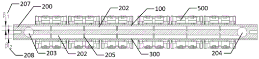
FIG. 4 is a cross-sectional view of the power module of FIG. 1 taken along the direction of coolant flow;
FIG. 5 is a cross-sectional view of the power module of FIG. 1 taken perpendicular to the direction of coolant flow;
FIG. 6 is a three-dimensional view of another power module according to an embodiment of the invention;
FIG. 7 is a three-dimensional view of the interior of the power module of FIG. 6;
FIG. 8 is a top view of the liquid-cooled substrate of FIG. 7;
FIG. 9 is a cross-sectional view of the power module of FIG. 6 taken perpendicular to the direction of coolant flow;
FIG. 10 is a cross-sectional view of the power module of FIG. 6 in the direction of coolant flow;
FIG. 11 is a three-dimensional view of a power module according to an embodiment of the present invention;
fig. 12 is a cross-sectional view of the power module of fig. 11 taken perpendicular to the direction of coolant flow.
Wherein in FIGS. 1-12:
100-a first closing plate;
200-a flow channel substrate, 201-a sealing surface, 202-a heat conduction flow channel, 203-a liquid inlet, 204-a liquid outlet, 205-a flow disturbing column, 206-an oblique angle, 207-a first slope surface and 208-a second slope surface;
300-a second sealing plate, 400-a connector and 500-a heating device.
Detailed Description
The core of the invention is to provide a liquid cooling plate, and the heat dissipation uniformity of the liquid cooling plate is improved. Another object of the present invention is to provide a power module including the above liquid-cooled plate.
In order to make the technical solutions of the present invention better understood by those skilled in the art, the present invention will be further described in detail with reference to the accompanying drawings and embodiments.
Please refer to fig. 1 to 12.
In a specific implementation manner, the liquid cooling plate according to an embodiment of the present invention includes a heat dissipation module, the heat dissipation module includes heat conduction fins, a heat conduction channel 202 is formed between two adjacent heat conduction fins, and an area of a heat conduction surface of the heat conduction channel 202, which is directly opposite to the heat generating device 500, is gradually increased along a flow direction of the coolant. Specifically, the heat conducting surface can be in a trapezoidal arrangement, and the heat conducting surface can also be formed by splicing rectangular structures with gradually increasing widths.
As shown in fig. 2 and 3, the heat dissipation module is one, and the heat conduction fin extends along the length direction of the liquid cooling plate. At this time, the heat generating devices 500 may be arranged in the coolant flow direction.
As shown in fig. 7 and 8, a plurality of heat dissipation modules are provided, and all the heat dissipation modules are sequentially arranged along the length direction of the liquid cooling plate. At this time, each heat dissipation module may correspond to one heat generating device 500. Preferably, the heat conducting channels 202 in the heat dissipation module are arranged along the width direction of the liquid cooling plate. The plurality of heat dissipation modules are arranged in parallel. Specifically, the liquid inlet 203 and the liquid outlet 204 of the heat conducting channel both extend to the edge heat dissipation module along the arrangement direction of the heat dissipation modules.
In the actual assembly process, the positions thereof may be arranged according to the specific structure of the heat generating device 500.
As can be seen from the above description, in the liquid cooling plate provided in the embodiment of the present application, since the area of the heat conduction channel 202, which is used for the heat conduction surface directly facing the heating device 500, is gradually increased along the flow direction of the coolant, the flow rate of the liquid in the channel or the contact area with the heating device 500 can be changed through the change of the channel, so that the temperatures before and after the heat conduction channel 202 can be balanced, the requirement of the series-parallel connection structure of more heating devices 500 can be met, that is, the heat exchange area is increased, and the heat dissipation uniformity of the liquid cooling plate is improved. Meanwhile, the problem of blockage of a narrow flow passage is avoided.
The depths of the heat conducting flow channels 202 may be the same, that is, the distances from the bottom ends of the heat conducting flow channels 202 to the heat conducting surface are the same.
In another embodiment, the flow cross-sections of the heat conducting flow channels 202 are identical, i.e. the cross-sections of the heat conducting flow channels 202 are identical in a direction perpendicular to the flow direction of the coolant. Of course, as shown in fig. 11 and 12, the flow cross section of the heat conducting flow passage 202 may be gradually reduced.
In yet another embodiment, as shown in FIG. 10, the flow cross-section of the thermally conductive flow path 202 may be gradually increased.
In one embodiment, the flow cross-section of the heat conducting flow channels 202 is trapezoidal or rectangular in a direction perpendicular to the flow direction of the coolant. Preferably, the heat conducting surface forms a long side of the trapezoid, and the bottom of the heat conducting channel 202 forms a short side of the trapezoid, that is, the heat conducting channel 202 is flared toward the heat conducting surface. The heat conduction flow channel 202 of this application adopts the trapezoidal groove structure, through the difference around the runner for the heat of device 500 that generates heat around is taken away by balanced, has guaranteed the temperature uniformity problem of many parallelly connected modules, also can effectively avoid the runner to block up the problem simultaneously. Meanwhile, the trapezoidal groove is convenient to process, the adjustable controllability of the shape of the flow channel is strong, the flow channel is easy to realize, and the flow channel is beneficial to mass production.
Specifically, one or both sides of the heat conducting flow channel 202 are slope surfaces, or the side surfaces of the heat conducting flow channel 202 are straight surfaces. Specifically, when both sides of the heat conducting flow channel 202 are slope surfaces, the angle β 1 of the first slope surface 207 and the angle β 2 of the second slope surface 208 of the heat conducting flow channel 202 may be changed to change the depth change of the heat conducting flow channel 202, or the angle α of the oblique angle 206 of the flow channel may be changed to change the width of the heat conducting flow channel 202, so as to change the flow rates at different cross sections of the heat conducting flow channel 202 and the area of the heat conducting surface in contact with the heat generating module. The angles of the first slope surface 207, the second slope surface 208 and the bevel angle 206 can be adjusted according to actual heat dissipation requirements, and can be fixed values or variable values.
During specific processing, the heat-conducting fins are in a straight-plate structure, a curved-surface structure, a broken-line structure or a snake-shaped structure. Specifically, the heat conducting fins can be formed by machining, and the machining is convenient and low in cost. When the heat-conducting fins are straight-bar structures, the heat-conducting flow channels 202 are straight-bar flow channels.
In one embodiment, a turbulence column 205 is disposed within the heat conducting flow channel 202. The flow disturbance column 205 is arranged to enable flowing substances in the heat conduction flow channel 202 to be disturbed, so that the temperature of the same section in the heat conduction flow channel 202 is balanced; the turbulence column 205 can be directly machined, or can be implemented as the turbulence column 205 by embedding a round rod. Preferably, the turbulence columns 205 are sequentially arranged in the heat conduction channel 202 along the flowing direction of the cooling liquid, the sizes of the turbulence columns 205 in the heat conduction channel 202 may be the same or different, specifically, the flowing direction of the cooling liquid may be used, and the peripheral sizes of the turbulence columns 205 are gradually increased.
In one embodiment, the liquid cooling plate further includes a flow channel substrate 200 and a sealing plate hermetically connected to the flow channel substrate 200, a placing cavity for placing a heat dissipation module is formed between the flow channel substrate 200 and the sealing plate, and a heat dissipation surface of the heat dissipation module is located on the sealing plate. The turbulence column 205 can be directly processed on the flow channel substrate 200, or can be embedded in the flow channel substrate 200 for installation. Specifically, the heat dissipation module is mounted on the flow channel substrate 200. Of course, the heat dissipation module may also be mounted on the sealing plate. When the heat dissipation module is mounted on the flow channel substrate 200, preferably, the flow channel substrate 200 is provided with a liquid inlet 203 and a liquid outlet 204, wherein the liquid inlet 203 and the liquid outlet 204 are respectively provided with a connector 400 for connecting with an external pipeline. The water inlet and outlet connectors of the connector 400 are used to connect the liquid cooling plate with an external water cooling system and also can directly connect the external water cooling system with the flow channel substrate 200.
The heat-conducting fins 205 may be directly formed on the flow channel substrate 200, or embedded heat-conducting fins 205 may be used. In order to improve the assembly efficiency, it is preferable that the heat dissipation module and the flow channel substrate 200 are integrally formed. The heat conducting fins 205 are convenient to process, the adjustable controllability of the shape of the flow channel is strong, the processing cost is low, and the mass production is facilitated.
In one embodiment, the heat dissipation module is disposed on one side of the flow channel substrate 200, i.e., the heat generating device 500 is disposed on only one side of the liquid cooling plate.
In another embodiment, heat dissipation modules are disposed on two sides of the flow channel substrate 200 facing away from the top. At this time, preferably, there are two sealing plates, namely the first sealing plate 100 and the second sealing plate 300, the two sides of the flow channel substrate 200, which are arranged away from each other, are both provided with heat dissipation modules, the first sealing plate 100 and the second sealing plate 300 are respectively and sealingly arranged on the two sides of the flow channel substrate 200, which are arranged away from each other, specifically, one of the first sealing plate 100 and the second sealing plate 300 is located on the upper side of the flow channel substrate 200, and the other is located on the lower side of the flow channel substrate 200. Specifically, the first sealing plate 100 and the second sealing plate 300 are in sealing fit with the flow channel substrate 200 through fastening members or welding or bonding, and the sealing effect of the heat conducting flow channel 202 is ensured. Specifically, the flow channel substrate 200 is provided with a sealing surface 201 for being attached to the sealing plate, and the sealing surface 201 and the sealing plate may be sealed by bonding, welding or providing a sealing member.
In order to improve the heat dissipation effect, preferably, the flow channel substrate 200 and/or the sealing plate are heat conducting members, and specifically, the flow channel substrate 200 and/or the sealing plate may be formed by processing a metal with a high heat conductivity coefficient. In order to prolong the service life of the liquid cooling plate, it is preferable that the flow channel substrate 200 and/or the sealing plate is formed by processing a corrosion-resistant section bar, or an anti-corrosion layer is provided on the surface of the flow channel substrate 200 and/or the sealing plate.
In one embodiment, a plurality of heat dissipation modules are stacked. Of course, there may be one heat dissipation module. Specifically, the flow channel substrate 200 may be arranged in a single layer or stacked, and then sealed by a sealing plate, thereby achieving a better heat dissipation effect.
The heat conduction flow channel 202 in the liquid cooling plate is simple in structure, low in processing cost, wide in flow channel, strong in flow channel shape adjustability, capable of being executed in multiple layers, easy to achieve mass production and cost-saving.
The application provides a pair of power module includes the liquid cooling board and installs the device 500 that generates heat on the liquid cooling board, and is concrete, and the liquid cooling board is above-mentioned arbitrary liquid cooling board. The foregoing describes a specific structure of the liquid cooling plate, and the present application includes the liquid cooling plate, which also has the technical effects described above.
The embodiments in the present description are described in a progressive manner, each embodiment focuses on differences from other embodiments, and the same and similar parts among the embodiments are referred to each other.
The previous description of the disclosed embodiments is provided to enable any person skilled in the art to make or use the present invention. Various modifications to these embodiments will be readily apparent to those skilled in the art, and the generic principles defined herein may be applied to other embodiments without departing from the spirit or scope of the invention. Thus, the present invention is not intended to be limited to the embodiments shown herein but is to be accorded the widest scope consistent with the principles and novel features disclosed herein.
Claims (20)
1. The liquid cooling plate is characterized by comprising a heat dissipation module, wherein the heat dissipation module comprises heat conduction fins, a heat conduction flow channel (202) is formed between every two adjacent heat conduction fins, and the area of a heat conduction surface, right opposite to a heating device (500), of the heat conduction flow channel (202) is gradually increased along the flowing direction of cooling liquid.
2. The liquid cooled plate of claim 1, wherein the number of heat dissipating modules is one, and the heat conducting fins extend along a length of the liquid cooled plate.
3. The liquid cooling plate of claim 1, wherein the number of the heat dissipation modules is plural, a plurality of the heat dissipation modules are arranged in parallel, and all the heat dissipation modules are sequentially arranged along the length direction of the liquid cooling plate.
4. The liquid cooling plate of claim 3, wherein the heat conducting flow channels (202) in the heat dissipating module are arranged along a width direction of the liquid cooling plate.
5. A liquid-cooled plate according to claim 1, characterized in that, in the direction of flow of the cooling liquid, the flow cross-sections of the heat-conducting flow channels (202) are identical, the flow cross-sections of the heat-conducting flow channels (202) are decreasing or the flow cross-sections of the heat-conducting flow channels (202) are increasing.
6. A liquid cold plate according to claim 1, wherein the flow cross-section of the heat conducting flow channel (202) is rectangular.
7. A liquid-cooled plate according to claim 1, wherein the flow cross-section of the heat conducting flow channel (202) is trapezoidal, the heat conducting surface forming the long side of the trapezoid and the bottom of the groove of the heat conducting flow channel (202) forming the short side of the trapezoid.
8. The liquid-cooled plate of claim 7, wherein one or both sides of the heat-conducting flow channel (202) are sloped or the sides of the heat-conducting flow channel (202) are flat.
9. The liquid cooled plate of claim 1, wherein the heat conducting fins are straight or curved or serpentine.
10. A liquid cooled plate according to claim 1, wherein turbulence columns (205) are provided in the heat conducting flow channels (202).
11. The liquid cooling plate of claim 1, further comprising a flow channel substrate (200) and a sealing plate hermetically connected to the flow channel substrate (200), wherein a cavity for placing the heat dissipation module is formed between the flow channel substrate (200) and the sealing plate, and a heat dissipation surface of the heat dissipation module is located on the sealing plate.
12. The liquid cold plate of claim 11, wherein said heat sink module is mounted on said flow channel substrate (200).
13. The liquid cooled plate of claim 12, wherein the liquid inlet (203) and the liquid outlet (204) are both provided on the flow channel substrate (200).
14. The liquid cold plate of claim 12, wherein said heat sink module and said flow channel substrate (200) are integrally formed.
15. A liquid-cooled plate according to claim 10, characterized in that the heat-dissipating module is provided on one side of the flow-channel substrate (200) or on both sides of the flow-channel substrate (200) facing away from it.
16. The liquid cooling plate of claim 15, wherein when the heat dissipation module is disposed on both sides of the flow channel substrate (200) facing away from the heat dissipation module, there are two sealing plates, namely a first sealing plate (100) and a second sealing plate (300), and the first sealing plate (100) and the second sealing plate (300) are respectively disposed on both sides of the flow channel substrate (200) facing away from the heat dissipation module in a sealing manner.
17. A liquid cooled plate according to claim 11, wherein the flow channel base plate (200) and the sealing plate are bonded, welded or both by sealing rings.
18. A liquid cooled plate according to claim 11, wherein the flow channel base plate (200) and/or the cover plate are heat conducting members.
19. The liquid cooled plate of any of claims 1-18, wherein the plurality of heat sink modules is stacked.
20. A power module comprising a liquid-cooled plate and a heat generating device (500) mounted on the liquid-cooled plate, wherein the liquid-cooled plate is according to any one of claims 1 to 19.
Priority Applications (1)
| Application Number | Priority Date | Filing Date | Title |
|---|---|---|---|
| CN202110175162.9A CN112928082A (en) | 2021-02-07 | 2021-02-07 | Liquid cooling plate and power module |
Applications Claiming Priority (1)
| Application Number | Priority Date | Filing Date | Title |
|---|---|---|---|
| CN202110175162.9A CN112928082A (en) | 2021-02-07 | 2021-02-07 | Liquid cooling plate and power module |
Publications (1)
| Publication Number | Publication Date |
|---|---|
| CN112928082A true CN112928082A (en) | 2021-06-08 |
Family
ID=76171324
Family Applications (1)
| Application Number | Title | Priority Date | Filing Date |
|---|---|---|---|
| CN202110175162.9A Pending CN112928082A (en) | 2021-02-07 | 2021-02-07 | Liquid cooling plate and power module |
Country Status (1)
| Country | Link |
|---|---|
| CN (1) | CN112928082A (en) |
Cited By (3)
| Publication number | Priority date | Publication date | Assignee | Title |
|---|---|---|---|---|
| CN113437037A (en) * | 2021-06-29 | 2021-09-24 | 中创杜菲(北京)汽车科技有限公司 | Package cooling device for power semiconductor |
| WO2023001012A1 (en) * | 2021-07-20 | 2023-01-26 | 北京比特大陆科技有限公司 | Hashboard and data processing device |
| WO2024050175A1 (en) * | 2022-08-29 | 2024-03-07 | Atieva, Inc. | Cooler for power electronics |
Citations (10)
| Publication number | Priority date | Publication date | Assignee | Title |
|---|---|---|---|---|
| JPH06349984A (en) * | 1993-06-08 | 1994-12-22 | Hitachi Ltd | Semiconductor integrated circuit device and cooling method therefor |
| JP2002130964A (en) * | 2000-08-09 | 2002-05-09 | Ts Heatronics Co Ltd | Thermal diffusion plate |
| JP2004200333A (en) * | 2002-12-18 | 2004-07-15 | Hitachi Ltd | Packaging structure of water cooling power semiconductor module |
| US20060250776A1 (en) * | 2005-05-05 | 2006-11-09 | Abul-Haj Roxanne E | Heatsink method and apparatus |
| JP2011004815A (en) * | 2009-06-23 | 2011-01-13 | Sankyo Co Ltd | Game machine |
| CN102227371A (en) * | 2008-09-30 | 2011-10-26 | 福斯德物理学有限责任公司 | Method and apparatus for control of fluid temperature and flow |
| JP2013197159A (en) * | 2012-03-16 | 2013-09-30 | Ihi Corp | Cooling device |
| JP2013197178A (en) * | 2012-03-16 | 2013-09-30 | Ihi Corp | Cooling device |
| US20140043765A1 (en) * | 2011-04-26 | 2014-02-13 | Fuji Electric Co., Ltd | Semiconductor module cooler and semiconductor module |
| CN107615479A (en) * | 2015-06-03 | 2018-01-19 | 三菱电机株式会社 | The manufacture method of the cold cooler of liquid and the radiating fin in the cold cooler of liquid |
-
2021
- 2021-02-07 CN CN202110175162.9A patent/CN112928082A/en active Pending
Patent Citations (10)
| Publication number | Priority date | Publication date | Assignee | Title |
|---|---|---|---|---|
| JPH06349984A (en) * | 1993-06-08 | 1994-12-22 | Hitachi Ltd | Semiconductor integrated circuit device and cooling method therefor |
| JP2002130964A (en) * | 2000-08-09 | 2002-05-09 | Ts Heatronics Co Ltd | Thermal diffusion plate |
| JP2004200333A (en) * | 2002-12-18 | 2004-07-15 | Hitachi Ltd | Packaging structure of water cooling power semiconductor module |
| US20060250776A1 (en) * | 2005-05-05 | 2006-11-09 | Abul-Haj Roxanne E | Heatsink method and apparatus |
| CN102227371A (en) * | 2008-09-30 | 2011-10-26 | 福斯德物理学有限责任公司 | Method and apparatus for control of fluid temperature and flow |
| JP2011004815A (en) * | 2009-06-23 | 2011-01-13 | Sankyo Co Ltd | Game machine |
| US20140043765A1 (en) * | 2011-04-26 | 2014-02-13 | Fuji Electric Co., Ltd | Semiconductor module cooler and semiconductor module |
| JP2013197159A (en) * | 2012-03-16 | 2013-09-30 | Ihi Corp | Cooling device |
| JP2013197178A (en) * | 2012-03-16 | 2013-09-30 | Ihi Corp | Cooling device |
| CN107615479A (en) * | 2015-06-03 | 2018-01-19 | 三菱电机株式会社 | The manufacture method of the cold cooler of liquid and the radiating fin in the cold cooler of liquid |
Cited By (3)
| Publication number | Priority date | Publication date | Assignee | Title |
|---|---|---|---|---|
| CN113437037A (en) * | 2021-06-29 | 2021-09-24 | 中创杜菲(北京)汽车科技有限公司 | Package cooling device for power semiconductor |
| WO2023001012A1 (en) * | 2021-07-20 | 2023-01-26 | 北京比特大陆科技有限公司 | Hashboard and data processing device |
| WO2024050175A1 (en) * | 2022-08-29 | 2024-03-07 | Atieva, Inc. | Cooler for power electronics |
Similar Documents
| Publication | Publication Date | Title |
|---|---|---|
| CN112928082A (en) | Liquid cooling plate and power module | |
| CN110164835B (en) | Manifold type micro-channel micro-radiator with complex structure | |
| JP5900507B2 (en) | Semiconductor module cooler and semiconductor module | |
| JP6093186B2 (en) | Semiconductor module cooler | |
| CN211831654U (en) | Efficient liquid cooling plate and equipment | |
| CN105576113A (en) | Semiconductor refrigeration component | |
| CN215418156U (en) | Microchannel copper-aluminum composite relieving liquid cooling radiator | |
| CN107084550A (en) | Semiconductor refrigerating component and ice cream maker | |
| WO2018209828A1 (en) | Liquid cooling heat dissipation device and motor controller | |
| CN111490448B (en) | Laser module | |
| WO2020019183A1 (en) | Heat dissipation structure for controller, and controller | |
| CN215988929U (en) | Liquid cooling system and battery device | |
| CN212695143U (en) | Micro-channel heat sink with vein-shaped flow dividing structure | |
| CN105514064A (en) | Heat sink | |
| CN113035805A (en) | Liquid cooling plate and power module | |
| JP2001284513A (en) | Power semiconductor device | |
| CN107275300B (en) | Modularized IGBT liquid cooling plate and manufacturing method thereof | |
| CN205542899U (en) | Semiconductor refrigeration components | |
| CN211125625U (en) | Liquid cooling heat dissipation assembly, liquid cooling heat dissipation device and power electronic equipment | |
| CN210325774U (en) | Liquid cooling radiator | |
| CN114615866A (en) | Liquid cooling plate and electronic equipment | |
| CN110831406B (en) | Efficient heat dissipation device for electronic device with ultrahigh heat flux density | |
| CN210325775U (en) | Liquid cooling radiator | |
| CN115279111A (en) | Liquid cooling plate and heat dissipation equipment | |
| CN105552049A (en) | Integrated liquid cooling heat sink device of power module and bottom plate used by power module |
Legal Events
| Date | Code | Title | Description |
|---|---|---|---|
| PB01 | Publication | ||
| PB01 | Publication | ||
| SE01 | Entry into force of request for substantive examination | ||
| SE01 | Entry into force of request for substantive examination |