CN112193507A - Carton buffer storage bin - Google Patents
Carton buffer storage bin Download PDFInfo
- Publication number
- CN112193507A CN112193507A CN202011199034.XA CN202011199034A CN112193507A CN 112193507 A CN112193507 A CN 112193507A CN 202011199034 A CN202011199034 A CN 202011199034A CN 112193507 A CN112193507 A CN 112193507A
- Authority
- CN
- China
- Prior art keywords
- carton
- buffer memory
- screw rod
- frame
- unloading
- Prior art date
- Legal status (The legal status is an assumption and is not a legal conclusion. Google has not performed a legal analysis and makes no representation as to the accuracy of the status listed.)
- Pending
Links
Images


Classifications
-
- B—PERFORMING OPERATIONS; TRANSPORTING
- B65—CONVEYING; PACKING; STORING; HANDLING THIN OR FILAMENTARY MATERIAL
- B65B—MACHINES, APPARATUS OR DEVICES FOR, OR METHODS OF, PACKAGING ARTICLES OR MATERIALS; UNPACKING
- B65B43/00—Forming, feeding, opening or setting-up containers or receptacles in association with packaging
- B65B43/12—Feeding flexible bags or carton blanks in flat or collapsed state; Feeding flat bags connected to form a series or chain
- B65B43/14—Feeding individual bags or carton blanks from piles or magazines
- B65B43/16—Feeding individual bags or carton blanks from piles or magazines by grippers
- B65B43/18—Feeding individual bags or carton blanks from piles or magazines by grippers by suction-operated grippers
- B65B43/185—Feeding individual bags or carton blanks from piles or magazines by grippers by suction-operated grippers specially adapted for carton blanks
Abstract
The invention innovatively provides a carton caching bin which can store cartons and can be matched with a manipulator to suck the cartons. This kind of carton buffer memory feed bin is including feed bin frame, its characterized in that: but install the blowing frame of back-and-forth movement in the feed bin frame, but install two relative backup pad subassemblies on the blowing frame, the backup pad subassembly is including backup pad and backup pad pivot, the backup pad pivot is rotationally installed on the blowing frame, the backup pad is connected in the backup pad pivot, be connected with the connecting piece in the backup pad pivot, the connecting piece is connected with one end of extension spring, another end of extension spring is connected on the blowing frame, the extension spring orders about the backup pad and turns to the inboard, the below of blowing frame is equipped with the blowing platform, the blowing platform is connected with the blowing power supply transmission of drive blowing platform oscila. This kind of carton buffer memory feed bin not only is convenient for the carton and deposits, and blowing platform ability automatic rising simultaneously cooperates the manipulator to absorb.
Description
Technical Field
The invention relates to a carton packaging machine, in particular to a storage device for cartons used for containing cartons.
Background
Generally, cartons (such as medicine boxes or other small cartons) are packed and packed into cartons, and currently, the packing of the cartons is completed by a carton packing machine, and then the cartons are manually packed. In order to realize automatic boxing, the applicant designs a full-automatic carton boxing device, and one of the processes of the full-automatic carton boxing device is to store cartons (boxing is in a flat state) so as to facilitate the mechanical arm to automatically take the cartons away one by one for subsequent carton boxing. There is not such carton strorage device in the existing market.
Disclosure of Invention
In view of the defects in the prior art, the invention innovatively provides the carton caching storage bin which can store cartons and can be matched with a manipulator to suck.
This kind of carton buffer memory feed bin is including feed bin frame, its characterized in that: but install the blowing frame of back-and-forth movement in the feed bin frame, but install two relative backup pad subassemblies on the blowing frame, the backup pad subassembly is including backup pad and backup pad pivot, the backup pad pivot is rotationally installed on the blowing frame, the backup pad is connected in the backup pad pivot, be connected with the connecting piece in the backup pad pivot, the connecting piece is connected with one end of extension spring, another end of extension spring is connected on the blowing frame, the extension spring orders about the backup pad and turns to the inboard, the below of blowing frame is equipped with blowing platform, blowing platform is connected with the blowing power supply transmission that drives the blowing platform oscilaltion.
Be equipped with carton buffer memory mechanism between blowing frame and the blowing platform, carton buffer memory mechanism all installs the buffer memory board subassembly including two front and back side baffles on two side baffles, buffer memory board subassembly is including buffer memory board, buffer memory board pivot and drive buffer memory board pivot pivoted buffer memory board power supply, the buffer memory board is connected in the buffer memory board pivot, the buffer memory board has the first state between two side baffles about getting into and the second state of coming out between two side baffles about from, and two buffer memory boards set up relatively around.
The side baffle plate is arranged on the front sliding seat and the rear sliding seat, the front sliding seat and the rear sliding seat are arranged on the front guide rail and the rear guide rail in a sliding mode, and the front sliding seat and the rear sliding seat can achieve front-back movement adjustment.
The feed bin is characterized in that a front screw rod and a rear screw rod are rotatably arranged on the feed bin rack, a front nut and a rear nut are arranged on the side baffle, the front nut and the rear nut are sleeved on the front screw rod and the rear screw rod, and the front screw rod and the rear screw rod are in transmission connection with a front-rear adjusting power source.
The side baffle is last to install and to control the guide rail, it is equipped with left and right sides slide to slide on the guide rail about, be connected with the locating plate on the slide about, the locating plate is located between two front and back side baffles, control the slide and can realize controlling the horizontal regulation.
The side baffle is rotatably provided with a left screw rod and a right screw rod, the left sliding seat and the right sliding seat are provided with a left nut and a right nut, the left nut and the right nut are sleeved on the left screw rod and the right screw rod, and the left screw rod and the right screw rod are in transmission connection with a left adjusting power source and a right adjusting power source.
The discharging device is characterized in that a discharging transmission mechanism is installed at a position, opposite to the discharging frame, on the stock bin rack, the discharging transmission mechanism comprises a discharging connecting rod and a discharging power source for driving the discharging connecting rod to move up and down, a groove is formed in the discharging connecting rod, and a discharging roller capable of entering the groove is arranged on the connecting piece.
The unloading connecting rod is connected on first connecting arm, first connecting arm is connected in the unloading pivot, the rotatable installation in feed bin frame of unloading pivot, the unloading pivot is connected with the transmission of unloading power supply.
First linking arm all has two with the unloading pivot, all is connected with the third linking arm in every unloading pivot, is equipped with the transmission connecting rod between two third linking arms, transmission connecting rod one end is articulated with a third linking arm, and the other end is articulated with another third linking arm.
According to the carton caching storage bin provided by the invention, the carton is convenient to store, and meanwhile, the discharging platform can be automatically lifted and matched with a manipulator for suction.
Drawings
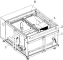
FIG. 1 is a perspective view of the present invention;
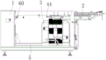
FIG. 2 is a side view of the present invention;
FIG. 3 is a perspective view of the interior of the present invention;
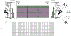
FIG. 4 is a front view of the discharge frame;
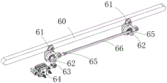
FIG. 5 is a schematic structural view of a blanking transmission mechanism;
FIG. 6 is a front view of the blanking drive mechanism;
FIG. 7 is a front view of the carton buffering mechanism;
fig. 8 is a side view of a carton buffering mechanism.
Detailed Description
As shown in fig. 1, the carton buffer bin is used for storing flat cartons a. A stack of flat cartons a is placed in the magazine and is sucked off one by the robot.
As shown in fig. 2, the carton buffer storage bin comprises a bin frame 1, a material placing frame 2 capable of moving back and forth is mounted on the bin frame 1, as shown in fig. 4, two opposite support plate assemblies 4 are mounted on the material placing frame 2, each support plate assembly 4 comprises a support plate 40 and a support plate rotating shaft 42, wherein the support plate rotating shaft 42 is rotatably mounted on the material placing frame 2, the support plate 40 is connected to the support plate rotating shaft 42, the support plate rotating shaft 42 is connected with a connecting piece 41, the connecting piece 41 is connected with one end of a tension spring 43, the other end of the tension spring 43 is connected to the material placing frame 1, and the tension spring 43 drives the support plate 40 to turn; and a material placing platform 5 is arranged below the material placing frame 2, and the material placing platform 5 is in transmission connection with a material placing power source 50 for driving the material placing platform 5 to lift up and down.
When the carton needs to be placed, the carton A is placed on the placing frame 2, as shown in FIG. 4, the support plates are pulled by the tension springs 43 to rotate to the inner side of the support plates 40, so that the carton A is placed on the support plates 40 at both sides, and meanwhile, the tension springs 43 pull the support plates 40 to prevent the support plates 40 from rotating outwards under the gravity of the carton. When the carton on the placing platform 5 is used up, the supporting plate rotating shaft 42 is rotated to turn the supporting plate 40 to the outer side, so that the carton A falls on the placing platform 5 below. The material placing platform 5 is driven by the material placing power source 50 to lift up and down, when the manipulator sucks away one piece, the material placing platform 5 rises by the height of the thickness of one paper box (the control can be realized by a sensor and the control can also be realized by programming), so that the suction point of the manipulator is unchanged, and the paper boxes are sucked and taken away one by one. Through the structure, the operation personnel only need to pull out the emptying frame 2 and then push the carton on the emptying platform 5, when the carton on the emptying platform 5 is used up, the supporting plate rotating shaft 42 is controlled to rotate, and the carton falls to the ground on the emptying platform 5, so that the operation is very safe and very convenient.
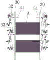
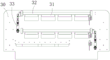
In order to buffer a large number of cartons a, a carton buffer mechanism 3 is arranged between the emptying frame 2 and the emptying platform 5, as shown in fig. 7 and 8, the carton buffer mechanism 3 includes a front side baffle plate and a rear side baffle plate 30, and buffer plate assemblies are mounted on the two side baffle plates 30, as shown in fig. 7, each buffer plate assembly includes a buffer plate 31, a buffer plate rotating shaft 32, and a buffer plate power source 33 for driving the buffer plate rotating shaft 32 to rotate, the buffer plates 31 are connected to the buffer plate rotating shaft 32, and driven by the buffer plate power source 33, the buffer plates 31 have a first state entering between the left and right side baffle plates 30 and a second state coming out from between the left and right side baffle plates 30 (the side baffle plates 30 have windows for the buffer plates 31 to go in and out), and the front and rear buffer plates 31 are arranged opposite to each other. If there is a carton on the placing platform 5, the carton placed on the placing frame 2 falls into the carton buffer mechanism 3 first, that is, the carton falls on the buffer plates 31 on the left and right sides for buffer storage, when there is no carton on the placing platform 5, the buffer plate power source 33 drives the buffer plates 31 to rotate, so that the carton a falls on the placing platform 5 below. Certainly, the carton of carton buffer memory mechanism 3 is transferred and can be controlled by the manual work, also can control buffer memory board power supply 33 action after the sensor response. It should be noted here that the carton buffer mechanism 3 can be arranged in multiple layers, that is, a plurality of buffer plate assemblies are arranged on the side baffle 30 along the up-down direction, so that the height of the carton buffer mechanism 3 can be set higher, and more cartons can be buffered. As shown in fig. 7, the carton buffer mechanism 3 is provided in two layers.
The width of the carton is different, and in order to meet the requirement of caching the cartons with different widths, as shown in fig. 3, the side baffles 30 are arranged on the front and rear sliding seats which are arranged on the front and rear guide rails 35 in a sliding manner, and the front and rear sliding seats can realize forward and backward movement adjustment. Since the cartons are stored in the front side baffle 30 and the rear side baffle 30, the front sliding seat and the rear sliding seat can be adjusted by carrying the side baffles 30 on the front guide rail 35 and the rear guide rail 35, so that the carton buffer device can be suitable for the buffer storage of the cartons with different widths.
In order to automatically complete adjustment, a front screw rod 36 and a rear screw rod 36 are rotatably arranged on the bin rack 1, front nuts and rear nuts are arranged on the side baffle plates 30 and are sleeved on the front screw rod 36 and the rear screw rod 36, and the front screw rod 36 and the rear screw rod 36 are in transmission connection with a front-rear adjusting power source 37. During adjustment, the front and rear adjusting power source 37 drives the front and rear screw rods 36 to rotate, and the front and rear nuts on the front and rear screw rods 36 move forward and backward, so that the side baffle 30 can realize forward and backward movement adjustment.
The length of the carton is different, in order to meet the requirement of caching the cartons with different lengths, a left guide rail 38 and a right guide rail 38 are installed on the side baffles 30, a left sliding seat and a right sliding seat are arranged on the left guide rail 38 in a sliding mode, a positioning plate 34 is connected to the left sliding seat and the right sliding seat, the positioning plate 34 is located between the front side baffle 30 and the rear side baffle 30, and the left sliding seat and the right sliding seat. The retaining plate 34 blocks the carton from the side, and when the left and right sliders carry the retaining plate 34 to move and adjust on the left and right guide rails 38, the carton can be accommodated for buffering cartons with different lengths.
Similarly, in order to automatically complete the adjustment, a left screw rod 39 and a right screw rod 39 are rotatably arranged on the side baffle 30, a left nut and a right nut are arranged on the left sliding seat and the right sliding seat, the left nut and the right nut are sleeved on the left screw rod 39 and the right screw rod 39, and the left screw rod 39 and the right screw rod 39 are in transmission connection with a left adjusting power source and. During adjustment, the left and right adjusting power source drives the left and right screw rods 39 to rotate, and the left and right nuts on the left and right screw rods 39 move left and right, so that the positioning plate 34 can be adjusted left and right.
When the carton on the discharging frame 2 is lowered, the carton can be prevented from being supported by the supporting plate 40 by manually rotating the supporting plate rotating shaft 42 of the supporting plate component 4, so that the carton can fall down; the support plate rotating shaft 42 of the support plate assembly 4 can be in transmission connection with a power source, the power source drives the support plate rotating shaft 42 to rotate, the support plate 40 no longer supports the carton, and the carton can fall down. These two kinds of modes can both make the carton transfer, and only the former needs to pass through the manual work, does not accord with automatic requirement, and the circuit problem (because the power supply will move with blowing frame 2 together, the circuit of connecting the power supply also can move) needs to be considered to the latter. In order to realize automation and avoid the problem of power source circuit, the invention is provided with a blanking transmission mechanism 6 at the position opposite to the discharging frame 2 on the stock bin rack 1, as shown in fig. 5 and 6, the blanking transmission mechanism 6 comprises a blanking connecting rod 60 and a blanking power source 64 for driving the blanking connecting rod 60 to move up and down, the blanking connecting rod 60 is provided with a groove 600, and the connecting piece 41 is provided with a blanking roller 44 capable of entering the groove 600. As shown in fig. 2, when the material placing frame 2 is pushed forward to a proper position, the material placing roller 44 on the connecting member 41 enters the groove 600 of the material placing connecting rod 60, the material placing power source 64 drives the material placing connecting rod 60 to move upward, so that the connecting member 41 of the supporting plate assembly 4 can rotate, and the connecting member 41 drives the supporting plate rotating shaft 42 to rotate, so that the supporting plate 40 no longer supports the carton a, and the carton a can fall down. Through this kind of structure, can realize the automation and fall, simultaneously because unloading drive mechanism 6 is installed and is not shifted on feed bin frame 1, consequently just need not consider power supply circuit and remove the problem, overall structure is reasonable compacter. It should be noted here that the blanking roller 44 is connected to the connecting member 41, and the connecting member 41 can rotate around the supporting plate rotating shaft 42 for adjusting the angle, so that the blanking roller 44 can be adjusted in position to align with the groove 600 of the blanking connecting rod 60, and meanwhile, the blanking roller 44 can move up and down through the connecting member 41 to drive the supporting plate rotating shaft 42 to rotate.
In order to drive the blanking connecting rod 60, as shown in fig. 5, the blanking connecting rod 60 is connected to a first connecting arm 61, the first connecting arm 61 is connected to a blanking rotating shaft 62, the blanking rotating shaft 62 is rotatably mounted on the silo frame 1, a second connecting arm 63 is mounted on the blanking rotating shaft 62, and the second connecting arm 63 is in transmission connection with a blanking power source 64. The blanking power source 64 drives the second connecting arm 63 to drive the blanking rotating shaft 62 to rotate, the blanking rotating shaft 62 drives the first connecting arm 61 to rotate, and the first connecting arm 61 finally drives the blanking connecting rod 60 to act, so that the carton is finally controlled to be lowered.
Since the two blanking rollers 44 need to be lifted up by the blanking connecting rod 60 (because of two opposite supporting plate assemblies), the balance degree of the blanking connecting rod 60 during ascending and descending must be ensured, as shown in fig. 5, there are two first connecting arms 61 and two blanking rotating shafts 62 according to the present invention, the blanking connecting rod 60 is connected to the two first connecting arms 61, each blanking rotating shaft 62 is connected to a third connecting arm 65, a transmission connecting rod 66 is arranged between the two third connecting arms 65, one end of the transmission connecting rod 66 is hinged to one third connecting arm 65, and the other end is hinged to the other third connecting arm 65. Through the structure, as long as the blanking power source 64 drives the second connecting arm 63 to rotate, the two first connecting arms 61 can be simultaneously driven to rotate, and the two first connecting arms 61 are connected through the transmission connecting rod 66, so that the two first connecting arms 61 are necessarily synchronously operated, the two points simultaneously drive the blanking connecting rod 60, the blanking connecting rod 60 is always in a horizontal position when moving up and down, the force applied by the blanking connecting rod 60 to the two blanking rollers 44 is the same, and the rotation of the two supporting plates 40 is completely synchronous.
Claims (9)
1. The utility model provides a carton buffer memory feed bin, includes feed bin frame (1), its characterized in that: a discharging frame (2) capable of moving back and forth is arranged on the stock bin rack (1), two opposite supporting plate assemblies (4) are arranged on the discharging frame (2), the supporting plate component (4) comprises a supporting plate (40) and a supporting plate rotating shaft (42), the supporting plate rotating shaft (42) is rotatably arranged on the discharging frame (1), the supporting plate (40) is connected on the supporting plate rotating shaft (42), the supporting plate rotating shaft (42) is connected with a connecting piece (41), the connecting piece (41) is connected with one end of a tension spring (43), the other end of the tension spring (43) is connected to the discharging frame (1), the tension spring (43) drives the supporting plate (40) to rotate to the inner side, a discharging platform (5) is arranged below the discharging frame (1), and the discharging platform (5) is in transmission connection with a discharging power source (50) for driving the discharging platform (5) to ascend and descend.
2. The carton buffering bin according to claim 1, wherein: be equipped with carton buffer memory mechanism (3) between blowing frame (2) and blowing platform (4), carton buffer memory mechanism (3) all installs buffer memory board subassembly on two side baffles (30) including two side baffles (30) around, buffer memory board subassembly is including buffer memory board (31), buffer memory board pivot (32) and drive buffer memory board pivot (32) pivoted buffer memory board power supply (33), buffer memory board (31) are connected on buffer memory board pivot (32), buffer memory board (31) have about getting into the first state between two side baffles (30) and from about the second state of coming out between two side baffles (30), two buffer memory boards (31) set up relatively around.
3. The carton buffering bin according to claim 2, wherein: the side baffle plates (30) are arranged on a front sliding seat and a rear sliding seat, the front sliding seat and the rear sliding seat are arranged on a front guide rail and a rear guide rail (35) in a sliding mode, and the front sliding seat and the rear sliding seat can achieve front-back movement adjustment.
4. The carton buffering bin according to claim 3, wherein: the feed bin is characterized in that a front screw rod and a rear screw rod (36) are rotatably arranged on the feed bin rack (1), a front nut and a rear nut are arranged on the side baffle plate (30), the front nut and the rear nut are sleeved on the front screw rod and the rear screw rod (36), and the front screw rod and the rear screw rod (36) are in transmission connection with a front adjusting power source and a rear adjusting power source (37).
5. The carton buffering bin according to claim 2, wherein: guide rail (38) about installing on side plate washer (30), slide about being equipped with on guide rail (38) about, be connected with locating plate (34) on the slide about, locating plate (34) are located between two front and back side plate washers (30), control the slide and can realize controlling the regulation.
6. The carton buffering bin according to claim 5, wherein: the side baffle plate (30) is rotatably provided with a left screw rod and a right screw rod (39), the left sliding seat and the right sliding seat are provided with a left nut and a right nut, the left nut and the right nut are sleeved on the left screw rod and the right screw rod (39), and the left screw rod and the right screw rod (39) are in transmission connection with a left adjusting power source and a right adjusting power source.
7. The carton buffering bin according to claim 1, wherein: unloading drive mechanism (6) are installed with the relative position of blowing frame (2) on feed bin frame (1), unloading drive mechanism (6) are including unloading connecting rod (60) and drive unloading connecting rod (60) unloading power supply (64) that reciprocate, be equipped with recess (600) on unloading connecting rod (60), be equipped with unloading gyro wheel (44) that can get into recess (600) on connecting piece (41).
8. The carton buffering bin according to claim 7, wherein: unloading connecting rod (60) are connected on first connecting arm (61), first connecting arm (61) are connected in unloading pivot (62), rotatable the installing on feed bin frame (1) of unloading pivot (62), unloading pivot (62) are connected with unloading power supply (64) transmission.
9. The carton buffering bin according to claim 8, wherein: first linking arm (61) all have two with unloading pivot (62), all are connected with third linking arm (65) on every unloading pivot (62), are equipped with between two third linking arms (65) transmission connecting rod (66), transmission connecting rod (66) one end is articulated with a third linking arm (65), and the other end is articulated with another third linking arm (65).
Priority Applications (1)
| Application Number | Priority Date | Filing Date | Title |
|---|---|---|---|
| CN202011199034.XA CN112193507A (en) | 2020-10-31 | 2020-10-31 | Carton buffer storage bin |
Applications Claiming Priority (1)
| Application Number | Priority Date | Filing Date | Title |
|---|---|---|---|
| CN202011199034.XA CN112193507A (en) | 2020-10-31 | 2020-10-31 | Carton buffer storage bin |
Publications (1)
| Publication Number | Publication Date |
|---|---|
| CN112193507A true CN112193507A (en) | 2021-01-08 |
Family
ID=74010659
Family Applications (1)
| Application Number | Title | Priority Date | Filing Date |
|---|---|---|---|
| CN202011199034.XA Pending CN112193507A (en) | 2020-10-31 | 2020-10-31 | Carton buffer storage bin |
Country Status (1)
| Country | Link |
|---|---|
| CN (1) | CN112193507A (en) |
Cited By (1)
| Publication number | Priority date | Publication date | Assignee | Title |
|---|---|---|---|---|
| CN112849534A (en) * | 2021-01-26 | 2021-05-28 | 研茂智能装备(苏州)有限公司 | Temporary storage assembly for carton |
-
2020
- 2020-10-31 CN CN202011199034.XA patent/CN112193507A/en active Pending
Cited By (1)
| Publication number | Priority date | Publication date | Assignee | Title |
|---|---|---|---|---|
| CN112849534A (en) * | 2021-01-26 | 2021-05-28 | 研茂智能装备(苏州)有限公司 | Temporary storage assembly for carton |
Similar Documents
| Publication | Publication Date | Title |
|---|---|---|
| CN110127121B (en) | Box filling machine | |
| CN1406819A (en) | Method and apparatus for feeding packing materials to operating mechanism | |
| CN201383495Y (en) | Automatic feeding device | |
| CN112193507A (en) | Carton buffer storage bin | |
| CN210391708U (en) | Case feeding mechanism of carton unpacking machine | |
| CN213862894U (en) | Carton buffer storage bin | |
| CN116605639B (en) | Material receiving equipment for chip test | |
| CN218022492U (en) | Carton sheet storage part | |
| CN216503273U (en) | High-speed rotation assembly mechanism for lens and lens assembly module | |
| CN211769333U (en) | Automatic cardboard turnover mechanism | |
| CN114055120A (en) | High-speed rotation assembly mechanism for lens and lens assembly module | |
| CN111018325B (en) | Tube feeding device and tube feeding method of automatic tube feeding machine of bottle making machine | |
| KR101764778B1 (en) | Box Delivery Device Of Flexible Erector System | |
| CN210794522U (en) | Adjustable bin adjusting mechanism of adjustable bin ejection cabinet type machine | |
| CN210619486U (en) | Full-automatic plate frame entering machine | |
| CN113895149A (en) | Turning device of paper feeder of double-sided printing equipment | |
| CN214983561U (en) | Paperboard feeding device | |
| CN218463276U (en) | Printing device for corrugated board | |
| CN217671369U (en) | Be applied to cardboard storage platform on box folding machine | |
| CN112059045A (en) | Plate carrying device for punching machine | |
| CN218663668U (en) | Automatic assembly line equipment for stack stacking | |
| CN110355547A (en) | A kind of material-dividing and delivery of torsional spring | |
| CN218051217U (en) | Loading production line for engine assembly | |
| CN218560338U (en) | Automatic boxing equipment | |
| CN111018326B (en) | Material pipe transfer mechanism and transfer method of automatic pipe feeding machine of bottle making machine |
Legal Events
| Date | Code | Title | Description |
|---|---|---|---|
| PB01 | Publication | ||
| PB01 | Publication | ||
| SE01 | Entry into force of request for substantive examination | ||
| SE01 | Entry into force of request for substantive examination |