CN112097603A - Cylinder part detection device - Google Patents
Cylinder part detection device Download PDFInfo
- Publication number
- CN112097603A CN112097603A CN202010964753.XA CN202010964753A CN112097603A CN 112097603 A CN112097603 A CN 112097603A CN 202010964753 A CN202010964753 A CN 202010964753A CN 112097603 A CN112097603 A CN 112097603A
- Authority
- CN
- China
- Prior art keywords
- frame
- fixed
- plate
- detection mechanism
- cylinder
- Prior art date
- Legal status (The legal status is an assumption and is not a legal conclusion. Google has not performed a legal analysis and makes no representation as to the accuracy of the status listed.)
- Granted
Links
Images


Classifications
-
- G—PHYSICS
- G01—MEASURING; TESTING
- G01B—MEASURING LENGTH, THICKNESS OR SIMILAR LINEAR DIMENSIONS; MEASURING ANGLES; MEASURING AREAS; MEASURING IRREGULARITIES OF SURFACES OR CONTOURS
- G01B5/00—Measuring arrangements characterised by the use of mechanical techniques
- G01B5/08—Measuring arrangements characterised by the use of mechanical techniques for measuring diameters
- G01B5/12—Measuring arrangements characterised by the use of mechanical techniques for measuring diameters internal diameters
-
- G—PHYSICS
- G01—MEASURING; TESTING
- G01B—MEASURING LENGTH, THICKNESS OR SIMILAR LINEAR DIMENSIONS; MEASURING ANGLES; MEASURING AREAS; MEASURING IRREGULARITIES OF SURFACES OR CONTOURS
- G01B21/00—Measuring arrangements or details thereof, where the measuring technique is not covered by the other groups of this subclass, unspecified or not relevant
- G01B21/02—Measuring arrangements or details thereof, where the measuring technique is not covered by the other groups of this subclass, unspecified or not relevant for measuring length, width, or thickness
- G01B21/08—Measuring arrangements or details thereof, where the measuring technique is not covered by the other groups of this subclass, unspecified or not relevant for measuring length, width, or thickness for measuring thickness
-
- G—PHYSICS
- G01—MEASURING; TESTING
- G01B—MEASURING LENGTH, THICKNESS OR SIMILAR LINEAR DIMENSIONS; MEASURING ANGLES; MEASURING AREAS; MEASURING IRREGULARITIES OF SURFACES OR CONTOURS
- G01B5/00—Measuring arrangements characterised by the use of mechanical techniques
- G01B5/0002—Arrangements for supporting, fixing or guiding the measuring instrument or the object to be measured
- G01B5/0004—Supports
Landscapes
- Physics & Mathematics (AREA)
- General Physics & Mathematics (AREA)
- A Measuring Device Byusing Mechanical Method (AREA)
- Automatic Assembly (AREA)
Abstract
The invention provides a cylindrical part detection device, comprising: frame, elevating system, feed mechanism, first detection mechanism, carrying mechanism, second detection mechanism, sense position ware, third detection mechanism and control indicating device, packaging board surface mounting has the second detection mechanism who highly carries out short-term test to the part, frame surface is located second detection mechanism and corresponds the position and installs the third detection mechanism who detects work piece aperture maximize, and this cylinder part detection device surveys the maximum value and the minimum value of the hole diameter of cylinder spare and the height of cylinder spare, and it is stable, convenient to detect, carries out stable centre gripping, location and guide to the cylinder spare through setting up of carrying mechanism simultaneously, and the cooperation adopts feed mechanism to arrange the material loading to the cylinder spare and realizes full-automatic guide transportation work piece, and not only the material loading is convenient, quick, replaces artifical the participation moreover, and improve equipment's use safety is brand-new.
Description
Technical Field
The invention relates to the technical field of electronic circuit board detection, in particular to a cylindrical part detection device.
Background
The cylindrical part is a common part in hardware and is generally used for high-precision mechanical connection, so that the size requirement of the cylindrical part needs to reach certain precision.
The cylinder needs to align when production is accomplished and carries out the detection of size, traditional detection uses tools such as slide caliper to carry out the manual measurement through the manual work, this kind of measuring method not only efficiency is slow, and measurement accuracy can not obtain the guarantee in addition, also has corresponding equipment to carry out the size detection to the cylinder in present mechanical production, nevertheless also needs artifical material loading, the mechanical positioning of deuterogamying detects, the aspect of detection efficiency does not obtain the promotion, artifical too much participation machinery detects the process simultaneously, danger is higher.
Therefore, it is necessary to provide a new cylindrical part detecting device to solve the above technical problems.
Disclosure of Invention
In order to solve the technical problem, the invention provides a cylindrical part detection device capable of automatically feeding.
The invention provides a cylindrical part detection device, which comprises: frame, elevating system, feed mechanism, first detection mechanism, carrying mechanism, second detection mechanism, sense position ware, third detection mechanism and control indicating device, elevating system is installed to frame one side, elevating system includes grillage, electric putter, cover frame, line rail and encapsulation board, grillage and frame fixed connection, electric putter is installed to the grillage inboard, the outside cover of grillage is equipped with the cover frame, and electric putter stretch out and draw back end and cover frame fixed connection, grillage fixed surface has the line rail, and cover frame and line rail sliding connection, the cover frame is close to frame one side and is fixed with the encapsulation board, encapsulation board surface mounting has the second detection mechanism who highly carries out the short-term test to the part, frame surface is located second detection mechanism and corresponds the position and installs the third detection mechanism that detects work piece aperture maximize, the one end that third detection mechanism was kept away from at the frame top is installed the first detection mechanism that detects work piece aperture minimize The top surface of the frame is provided with position sensors at two sides of the first detection mechanism and the second detection mechanism, the top surface of the frame is provided with a carrying mechanism capable of linearly clamping and carrying workpieces in a reciprocating manner, one side of the top of the frame is provided with a feeding mechanism matched with the carrying mechanism, one side of the top of the frame is provided with a control indicating device, and the first detection mechanism, the second detection mechanism and the third detection mechanism are electrically connected with the control indicating device;
the position sensor comprises a mounting frame and an in-place sensor, the mounting frame is respectively fixed on the side edges of the first detection mechanism and the second detection mechanism, and the in-place sensor is mounted on the surface of the mounting frame;
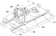
the carrying mechanism comprises a screw rod, a first motor, a transverse moving block, a sliding groove, a lifting mechanism, right-angle arms, a clamping mechanism and a connecting mechanism, the screw rod is symmetrically and rotatably installed on the top surface of the frame, the transverse moving block is installed outside the screw rod in a meshed mode, the sliding groove is symmetrically formed in the top surface of the frame, the bottom of the transverse moving block is in sliding connection with the sliding groove, the first motor is installed at the end part of the screw rod, the lifting mechanism is fixed to the top of the transverse moving block, the right-angle arms are installed at the moving ends of the lifting mechanism, the connecting mechanism is installed at the end parts of the right-angle arms;
feed mechanism includes guide frame, positive feed cylinder, stock stop and stop gear, the guide frame is the slope and sets up in the frame top, and guide frame and frame side fixed connection, guide frame bottom is located frame central part and is fixed with positive feed cylinder, guide frame surface is close to positive feed cylinder one end and installs stock stop, guide frame surface is located stock stop and keeps away from positive feed cylinder one side and installs stop gear.
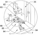
Preferably, first detection mechanism includes station board, strip hole, pneumatic measuring instrument, pillar, first cylinder and scute, first cylinder is installed to the roof bottom of frame, and the flexible end of first cylinder is fixed with the scute, scute top surface symmetry is fixed with the pillar, and the pillar slides and passes the frame and be fixed with the station board, the strip hole has been seted up on the station board surface, the frame top surface is located station board below and installs pneumatic measuring instrument, and pneumatic measuring instrument's sense terminal corresponds with strip hole position.
Preferably, the second detection mechanism comprises a base block, a height gauge, a probe, a station ring, a hollow plate and a chute, the base block is fixed on the surface of the packaging plate, the height gauge is mounted on the surface of the base block, the probe is connected to the bottom end of the height gauge, the station ring is mounted on the position, corresponding to the height gauge, of the surface of the frame, the hollow plate is fixed to the top of the station ring, and the chute is formed in the top surface of the hollow plate at equal intervals.
Preferably, the third detection mechanism comprises a guide hole, a standard column, a second cylinder and an infrared sensor, the second cylinder is installed at the bottom of a top plate of the frame, the standard column is installed at the telescopic end of the second cylinder, the guide hole is formed in the position, corresponding to the station circle, of the surface of the frame, the standard column penetrates through the guide hole to be led into the station circle, and the infrared sensor is installed on the side edge of the standard column of the surface of the frame.
Preferably, the lifting mechanism comprises a movable plate, a guide groove, a threaded column, a slide rail, a connecting block and a second motor, the movable plate is fixedly connected with the transverse moving block, the guide groove is formed in the surface of the movable plate, the threaded column is installed in the guide groove in a rotating mode, the second motor is installed at the top end of the threaded column, the connecting block is arranged in the guide groove in a matched mode and is meshed with the threaded column, the right-angle arm is fixedly connected with the connecting block, the surface of the movable plate is fixedly provided with the slide rail, and the right-angle arm is slidably connected with the slide rail.
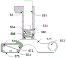
Preferably, linking up the mechanism and including second electro-magnet, elasticity box, elastic block, expanding spring and end post, the embedding of second electro-magnet is installed inside right angle arm, the elastic box is fixed to the flexible end of second electro-magnet, slidable mounting has elastic block in the elastic box, and elastic block passes through expanding spring and elasticity box elastic connection, the elastic block is kept away from second electro-magnet one end and is fixed with the end post, and the end post slides and wears out the elastic box.
Preferably, fixture includes grip block, motor, driving groove, driven pulleys, rubber belt and driving pulley, grip block and end post fixed connection, the inboard middle part of grip block is circular-arcly, the both sides symmetry that the grip block surface is located the circular arc structure has seted up the driving groove, the port position equidistance in driving groove rotates installs driven pulleys, driving groove internal rotation installs driving pulley, driven pulleys passes through the rubber belt transmission with driving pulley and is connected, the motor is installed to grip block outer wall symmetry, and motor output shaft corresponds fixed connection with driving pulley.
Preferably, the stock stop includes baffle, cantilever crane, even frame, first electro-magnet, swivel mount and half gear, the baffle is inserted in the one end that the guide frame is close to the positive feed cylinder, the baffle bilateral symmetry is fixed with the cantilever crane, the cantilever crane rotates with guide frame outer wall to be connected, the connection pivot outer wall fixed mounting of cantilever crane has even frame and half gear, guide frame bottom is fixed with the swivel mount, the swivel mount side rotates and installs first electro-magnet, and the flexible end of first electro-magnet rotates with even frame to be connected.
Preferably, stop gear is including dilatation shell, splint, sheet rubber, driven gear, drive gear, sliding sleeve, slide bar, silk post and a silk section of thick bamboo, the guide frame surface is located stock stop side symmetry and is fixed with the dilatation shell, all be provided with splint in the dilatation shell, and splint fixed surface has the sheet rubber, the splint outer wall is fixed with a silk section of thick bamboo, dilatation shell surface rotates installs the silk post, and the silk post is connected with a silk section of thick bamboo meshing, the outer end of silk post is fixed with driven gear, dilatation shell outer wall rotates and installs drive gear, drive gear is connected with driven gear meshing, drive gear is connected with half gear meshing, the splint surface is located a silk section of thick bamboo below and is fixed with the slide bar, dilatation shell surface fixing has the sliding sleeve, and slide bar and spout slip grafting.
Compared with the related art, the cylindrical part detection device provided by the invention has the following beneficial effects:
the invention provides a cylindrical part detection device:
1. the maximum value and the minimum value of the diameter of the inner hole of the cylindrical part and the height of the cylindrical part are measured through the arrangement of the first detection mechanism, the second detection mechanism and the third detection mechanism, compared with the traditional method that the measurement is carried out through a ruler manually, the measurement is more accurate, the workpiece is placed more stably through mechanical control, and the detection convenience is improved;
2. the cylindrical part is stably clamped, positioned and guided by the carrying mechanism, three detection items can be quickly penetrated through, and compared with the traditional semi-automatic operation mode that manual work participates in station transfer, the carrying mechanism is added, so that the transfer efficiency and precision of the cylindrical part are improved, the detection period is shortened, and the use safety of equipment is improved by replacing manual operation;
3. the conveying belt type clamping mechanism is adopted to adjust and clamp the cylindrical piece, so that clamping abrasion caused by alignment of the clamping mechanism due to deviation of the cylindrical piece is avoided, and protective clamping of the cylindrical piece is effectively guaranteed;
4. adopt feed mechanism to arrange the material loading to the cylinder spare, through stock stop and stop gear's linkage, realize single, controllable material loading of cylinder spare, the feeding that carries on of maximum efficiency detects, for traditional artifical material loading more convenient, high-efficient and stable.
Drawings
FIG. 1 is a schematic overall side view of the present invention;
FIG. 2 is a schematic diagram of an overall top view structure provided by the present invention;
FIG. 3 is a schematic structural view of a lifting mechanism provided in the present invention;
FIG. 4 is a schematic structural view of a second detecting mechanism provided in the present invention;
FIG. 5 is a schematic structural diagram of a first detecting mechanism provided in the present invention;
FIG. 6 is a schematic view of a first detecting mechanism and a driving structure of a second detecting mechanism provided by the present invention;
FIG. 7 is a schematic view of a carrying mechanism according to the present invention;
FIG. 8 is a schematic view of a lifting mechanism according to the present invention;
FIG. 9 is a schematic structural view of a clamping mechanism and an engaging mechanism provided in the present invention;
FIG. 10 is a schematic structural view of a feeding mechanism provided by the present invention;
fig. 11 is a schematic structural view of a material stop mechanism and a limiting mechanism provided by the invention;
FIG. 12 is a schematic view of a cleat driving connection provided by the present invention;
fig. 13 is a schematic bottom structure view of the stock stop and the limiting mechanism provided by the invention.
Reference numbers in the figures: 1. a frame; 2. a lifting mechanism; 21. a plate frame; 22. an electric push rod; 23. sleeving a frame; 24. a wire track; 25. a package board; 3. a feeding mechanism; 31. a material guiding frame; 32. a charging barrel is calibrated; 33. a stock stop mechanism; 331. a baffle plate; 332. a boom; 333. connecting a frame; 334. a first electromagnet; 335. rotating; 336. a half gear; 34. a limiting mechanism; 341. expanding the shell; 342. a splint; 343. a rubber sheet; 344. a driven gear; 345. a transmission gear; 346. a sliding sleeve; 347. a slide bar; 348. silk poles; 349. a wire barrel; 4. a first detection mechanism; 41. a station plate; 42. a bar hole; 43. a pneumatic measuring instrument; 44. a pillar; 45. a first cylinder; 46. a gusset; 5. a carrying mechanism; 51. a screw rod; 52. a first motor; 53. transversely moving the blocks; 54. a chute; 55. a lifting mechanism; 551. moving the plate; 552. a guide groove; 553. a threaded post; 554. a slide rail; 555. connecting blocks; 556. a second motor; 56. a right-angled arm; 57. a clamping mechanism; 571. a clamping plate; 572. a motor; 573. a drive slot; 574. a driven pulley; 575. a rubber belt; 576. a driving pulley; 58. a joining mechanism; 581. a second electromagnet; 582. an elastic case; 583. an elastic block; 584. a tension spring; 585. an end post; 6. a second detection mechanism; 61. a base block; 62. an altimeter; 63. a probe; 64. a station ring; 65. a hollow slab; 66. a chute; 7. a position sensing device; 71. a mounting frame; 72. an in-place sensor; 8. a third detection mechanism; 81. a guide hole; 82. a standard column; 83. a second cylinder; 84. an infrared sensor; 9. and controlling the indicating device.
Detailed Description
The invention is further described with reference to the following figures and embodiments.
Please refer to fig. 1, fig. 2, fig. 3, fig. 4, fig. 5, fig. 6, fig. 7, fig. 8, fig. 9, fig. 10, fig. 11, fig. 12 and fig. 13 in combination, wherein fig. 1 is a schematic overall side view structure provided by the present invention; FIG. 2 is a schematic diagram of an overall top view structure provided by the present invention; FIG. 3 is a schematic structural view of a lifting mechanism provided in the present invention; FIG. 4 is a schematic structural view of a second detecting mechanism provided in the present invention; FIG. 5 is a schematic structural diagram of a first detecting mechanism provided in the present invention; FIG. 6 is a schematic view of a first detecting mechanism and a driving structure of a second detecting mechanism provided by the present invention; FIG. 7 is a schematic view of a carrying mechanism according to the present invention; FIG. 8 is a schematic view of a lifting mechanism according to the present invention; FIG. 9 is a schematic structural view of a clamping mechanism and an engaging mechanism provided in the present invention; FIG. 10 is a schematic structural view of a feeding mechanism provided by the present invention; fig. 11 is a schematic structural view of a material stop mechanism and a limiting mechanism provided by the invention; FIG. 12 is a schematic view of a cleat driving connection provided by the present invention; fig. 13 is a schematic bottom structure view of the stock stop and the limiting mechanism provided by the invention. The cylindrical part detection device includes: the device comprises a frame 1, a lifting mechanism 2, a feeding mechanism 3, a first detection mechanism 4, a carrying mechanism 5, a second detection mechanism 6, a position sensor 7, a third detection mechanism 8 and a control indication device 9.
In the specific implementation process, as shown in fig. 3, a lifting mechanism 2 is installed at one side of the frame 1, the lifting mechanism 2 comprises a plate frame 21, an electric push rod 22, a sleeve frame 23, a wire track 24 and a packaging plate 25, the plate frame 21 is fixedly connected with the frame 1, the electric push rod 22 is arranged on the inner side of the plate frame 21, the sleeve frame 23 is sleeved outside the plate frame 21, the telescopic end of the electric push rod 22 is fixedly connected with a sleeve frame 23, a linear rail 24 is fixed on the surface of the plate frame 21, and the sleeve frame 23 is connected with the line rail 24 in a sliding way, one side of the sleeve frame 23 close to the frame 1 is fixed with a packaging plate 25, the surface of the packaging plate 25 is provided with a second detection mechanism 6 for rapidly detecting the height of the part, the frame 1 is an installation base of the device, the lifting mechanism 2 is used for driving the second detection mechanism 6 to lift, the electric push rod 22 is started to stretch and push the sleeve frame 23 to lift, and the sleeve frame 23 slides up and down along the linear rail 24 to drive the second detection mechanism 6 to lift so as to detect the height of the cylindrical part.
As shown in fig. 1 and 2, a third detection mechanism 8 for detecting the maximum aperture of the workpiece is installed at a position corresponding to the second detection mechanism 6 on the surface of the frame 1, a first detection mechanism 4 for detecting the minimum aperture of the workpiece is installed at one end of the top of the frame 1, which is far away from the third detection mechanism 8, a position sensor 7 is installed at both sides of the first detection mechanism 4 and the second detection mechanism 6, a carrying mechanism 5 capable of clamping and carrying the workpiece in a reciprocating linear manner is installed at the top of the frame 1, a feeding mechanism 3 matched with the carrying mechanism 5 is installed at one side of the top of the frame 1, a control indication device 9 is installed at one side of the top of the frame 1, and the first detection mechanism 4, the second detection mechanism 6 and the third detection mechanism 8 are all electrically connected with the control indication device 9;
the inner diameter minimum range of the cylindrical workpiece is detected through the first detection mechanism 4, the inner diameter maximum range of the cylindrical workpiece is detected through the third detection mechanism 8, the height of the cylindrical workpiece is detected through the second detection mechanism 6, the cylindrical workpiece is evenly conducted and discharged through the feeding mechanism 3, and the cylindrical workpiece is clamped and guided by the carrying mechanism 5 in a matching mode and runs through the whole detection process.
The control indicating device 9 is electrically installed and used for receiving feedback signals of the first detection mechanism 4, the second detection mechanism 6 and the third detection mechanism 8 and prompting whether each measurement index is qualified or not, and the working principle of the control indicating device 9 is that a logic circuit programmed by a specific single chip microcomputer receives corresponding electric signals and different signal lamps are started to achieve a prompting effect.
As shown in fig. 5, the position sensor 7 includes a mounting frame 71 and an in-place sensor 72, the mounting frame 71 is fixed to the side edges of the first detection mechanism 4 and the second detection mechanism 6, the in-place sensor 72 is mounted on the surface of the mounting frame 71, the in-place sensor 72 is an existing mature machining auxiliary part and is used for sensing the position of an object, and the mounting frame 71 is used for mounting and fixing the in-place sensor 72, so that the monitoring part of the in-place sensor 72 is aligned with two detection stations respectively and is used for sensing whether a workpiece is in place or not, so as to ensure that the workpiece is in place for machining, avoid vacant work of the detection stations, and reduce the damage rate of equipment;
as shown in fig. 7, the carrying mechanism 5 includes a screw 51, a first motor 52, a traverse block 53, a sliding groove 54, a lifting mechanism 55, right-angle arms 56, a clamping mechanism 57 and an engaging mechanism 58, the screw 51 is symmetrically and rotatably mounted on the top surface of the frame 1, the traverse block 53 is respectively engaged and mounted on the outer portion of the screw 51, the sliding grooves 54 are symmetrically formed on the top surface of the frame 1, the bottom of the traverse block 53 is slidably connected with the sliding grooves 54, the first motor 52 is mounted at the end of the screw 51, the lifting mechanism 55 is fixed at the top of the traverse block 53, the right-angle arms 56 are mounted at the moving ends of the lifting mechanism 55, the engaging mechanism 58 is mounted at the end of the right-angle arms 56, and the clamping mechanism 57 is connected and;
through first motor 52 drive spout 54 just reversing, make sideslip piece 53 drive hoist mechanism 55 along spout 54 reciprocating motion, through fixture 57 centre gripping work piece, be convenient for to the material loading of work piece, location, centre gripping and row material, run through whole process, replace artifical participation material loading, not only increase detection efficiency and accurate nature, improve the safety in utilization of device moreover.
As shown in fig. 8, the lifting mechanism 55 includes a moving plate 551, a guide groove 552, a threaded column 553, a slide rail 554, a connecting block 555, and a second motor 556, the moving plate 551 is fixedly connected with the traverse block 53, the surface of the moving plate 551 is provided with the guide groove 552, the threaded column 553 is rotatably mounted in the guide groove 552, the second motor 556 is mounted at the top end of the threaded column 553, the connecting block 555 is arranged in the guide groove 552 in a matching manner, the connecting block 555 is engaged with the threaded column 553, the right-angle arm 56 is fixedly connected with the connecting block 555, the surface of the moving plate 551 is provided with the slide rail 554, and the right-angle arm 56 is slidably connected with the slide rail 554.
The lifting mechanism 55 is arranged to drive the clamping mechanism 57 to lift, clamping lifting adjustment of the cylindrical piece is achieved, stable discharging of stations with different heights is achieved, material receiving is achieved through height matching during feeding, the second motor 556 is started to drive the threaded column 553 to rotate, the right-angle arm 56 drives the clamping mechanism 57 to lift and slide along the sliding rail 554 through meshing transmission of the connecting block 555, and clamping height adjustment of the cylindrical piece is achieved.
As shown in fig. 9, the engaging mechanism 58 includes a second electromagnet 581, an elastic box 582, an elastic block 583, a telescopic spring 584 and an end post 585, the second electromagnet 581 is embedded and installed inside the right-angle arm 56, the elastic box 582 is fixed on the telescopic end of the second electromagnet 581, the elastic block 583 is installed in the elastic box 582 in a sliding manner, the elastic block 583 is elastically connected with the elastic box 582 through the telescopic spring 584, the end post 585 is fixed on one end of the elastic block 583 far away from the second electromagnet 581, and the end post 585 slides out of the elastic box 582.
Linking mechanism 58 sets up and is used for promoting fixture 57 to open and shut and move, be the drive basis of centre gripping work, open the flexible elasticity box 582 that makes second electro-magnet 581 and drive fixture 57 and remove about, carry out centre gripping or release to the cylinder spare, and fixture 57 is connected with end post 585, through elastic block 583 and elasticity box 582 sliding connection, the elasticity of cooperation expanding spring 584 makes fixture 57's installation have certain elasticity, guarantee fixture 57 has buffer space to pressing the in-process, avoid fixture 57 to cause the destruction to the cylinder spare stereoplasm extrusion.
As shown in fig. 9, the clamping mechanism 57 includes a clamping plate 571, a motor 572, a driving groove 573, a driven pulley 574, a rubber belt 575 and a driving pulley 576, the clamping plate 571 is fixedly connected with the end post 585, the middle part of the inner side of the clamping plate 571 is arc-shaped, the driving grooves 573 are symmetrically formed on the surface of the clamping plate 571 located on two sides of the arc-shaped structure, the driven pulleys 574 are rotatably installed at the port positions of the driving groove 573 at equal intervals, the driving pulley 576 is rotatably installed inside the driving groove 573, the driven pulleys 574 and the driving pulley 576 are in transmission connection through the rubber belt 575, the motor 572 is symmetrically installed on the outer wall of the clamping plate 571, and the output shaft of the motor 572 is correspondingly and fixedly connected with the driving pulley 576.
The setting of fixture 57 is used for pressing centre gripping cylinder spare, the circular arc position and the cylinder structure cooperation of grip block 571, be used for extruding cylinder spare to carry out the centre gripping fixed, and can make the cylinder spare position skew because of reasons such as mechanical vibration before pressing the centre gripping, if direct centre gripping can lead to the fact extrusion wearing and tearing to harm to cylinder spare, open motor 572 drive driving pulley 576 and rotate, thereby make rubber tape 575 take place the transmission, and the rubber tape 575 of grip block 571 centre gripping position both sides is rotatory to middle part symmetry, when rubber tape 575 contacts the cylinder spare, because the revolving force makes the work piece move to the groove part gradually, until cylinder work piece is guided into the cooperation card in the recess and is held and accomplish the centre gripping, effectively avoid work piece pressurized wearing and tearing.
As shown in fig. 10, the feeding mechanism 3 includes a guide frame 31, a positive feed cylinder 32, a stop mechanism 33 and a limit mechanism 34, the guide frame 31 is inclined and arranged above the frame 1, and the guide frame 31 is fixedly connected with the side of the frame 1, the bottom end of the guide frame 31 is located at the center of the frame 1 and is fixed with the positive feed cylinder 32, the stop mechanism 33 is installed at one end of the guide frame 31 close to the positive feed cylinder 32 on the surface, and the limit mechanism 34 is installed at one side of the guide frame 31, which is far away from the positive feed cylinder 32, on the surface of the stop mechanism 33.
In order to facilitate uniform detection of large-batch cylindrical pieces, the guide frame 31 is adopted to uniformly guide the cylindrical pieces, the bottom cylindrical pieces vertically fall through the positive material cylinder 32, the bottom cylindrical pieces are blocked through the stop mechanism 33, uniform discharge of control is facilitated, the limiting mechanism 34 is arranged to clamp the second bottom cylindrical pieces, single discharge of the bottom cylindrical pieces is guaranteed, and feeding efficiency is greatly improved.
As shown in fig. 11 and 13, the material blocking mechanism 33 includes a blocking plate 331, an arm support 332, a connecting frame 333, a first electromagnet 334, a rotary seat 335 and a half gear 336, the blocking plate 331 is inserted into one end of the material guiding frame 31 close to the charging barrel 32, the arm supports 332 are symmetrically fixed on two sides of the blocking plate 331, the arm supports 332 are rotatably connected with the outer wall of the material guiding frame 31, the connecting frame 333 and the half gear 336 are fixedly installed on the outer wall of the connecting rotating shaft of the arm supports 332, the rotary seat 335 is fixed at the bottom of the material guiding frame 31, the first electromagnet 334 is rotatably installed on the side of the rotary seat 335, and the telescopic end of the first electromagnet 334 is rotatably connected with the connecting frame 333.
In order to realize uniform single blanking, the material blocking mechanism 33 is used for blocking the material at the bottommost end of the material guiding frame 31, the baffle 331 is inserted into the material guiding frame 31, the bottom surface of the cylindrical part at the bottommost end is in contact with the baffle 331, when the material is discharged, the first electromagnet 334 is started to contract, the connecting frame 333 is pulled to rotate, the arm support 332 is rotated upwards, the baffle 331 is rotated out of the material guiding frame 31, the cylindrical part slides into the positive material barrel 32 from the material guiding frame 31 to perform positive blanking, and the discharge control of the cylindrical part feeding is realized.
As shown in fig. 11 and 13, the limiting mechanism 34 includes an expansion shell 341, a clamping plate 342, a rubber sheet 343, a driven gear 344, a transmission gear 345, a sliding sleeve 346, a sliding rod 347, a wire column 348 and a wire cylinder 349, the expansion shell 341 is symmetrically fixed on the surface of the guide frame 31 at the side of the material stopping mechanism 33, the clamping plate 342 is disposed in each expansion shell 341, the rubber sheet 343 is fixed on the surface of the clamping plate 342, the wire cylinder 349 is fixed on the outer wall of the clamping plate 342, the wire column 348 is rotatably mounted on the surface of the expansion shell 341 and is engaged with the wire cylinder 349, the driven gear 344 is fixed at the outer end of the wire column 348, the transmission gear 345 is rotatably mounted on the outer wall of the expansion shell 341, the transmission gear 345 is engaged with the driven gear 344, the transmission gear 345 is engaged with the half gear 336, the sliding rod 347 is fixed on the surface of the clamping plate 342 below the wire cylinder 349, the sliding sleeve 346 is fixed on the surface of the expansion shell 341, and the sliding rod 347 is slidably inserted into the sliding groove 54.
In order to satisfy the requirement of single discharge, when the bottommost cylindrical member is discharged, it is necessary to ensure that the second cylindrical member at the bottom is not discharged, the arrangement of the limiting mechanism 34 effectively avoids this, when the connecting frame 333 rotates, the coaxially fixed half gear 336 rotates, the driven gear 344 drives the screw column 348 to rotate through the meshing transmission of the transmission gear 345, the screw cylinder 349 pushes the clamping plate 342 to move through the thread transmission of the screw column 348, the symmetrically moving clamp 342 clamps the second cylindrical member at the bottom, ensuring that only the bottommost cylindrical member is discharged, and when the baffle 331 is reset, the clamp 342 is driven to reset, so that the cylindrical member slides to the bottom of the material guiding frame 31 and is blocked by the baffle 331 to prepare for the next discharging, the rubber sheet 343 is mounted to protect the cylindrical member from being squeezed by the clamping plate 342, and the sliding sleeve 346 is slidably inserted into the sliding rod 347 to enable the clamping plate 342 to move in a telescopic manner, so that the stability of limiting squeezing is improved.
As shown in fig. 5 and 6, the first detection mechanism 4 includes a station plate 41, a bar hole 42, a pneumatic measuring instrument 43, a pillar 44, a first cylinder 45 and a corner plate 46, the first cylinder 45 is mounted at the bottom of the top plate of the frame 1, the corner plate 46 is fixed at the telescopic end of the first cylinder 45, the pillar 44 is symmetrically fixed at the top surface of the corner plate 46, the pillar 44 slides through the frame 1 to fix the station plate 41, the bar hole 42 is opened on the surface of the station plate 41, the pneumatic measuring instrument 43 is mounted on the top surface of the frame 1 below the station plate 41, and the detection end of the pneumatic measuring instrument 43 corresponds to the bar hole 42.
The workpiece is placed at the position of the strip hole 42 on the surface of the station plate 41 through the carrying mechanism 5, the first air cylinder 45 is started to contract, the angle plate 46 drives the support 44 to move downwards, the station plate 41 moves downwards, the pneumatic measuring instrument 43 is inserted into the cylindrical piece to detect the inner diameter of the cylindrical piece, and the station plate 41 pushes the cylindrical piece to reset after the detection is finished.
The pneumatic measuring instrument 43 is an existing device, and its principle is to convert the airflow pressure into a length value through an air-electric converter, and to perform conversion and transmission of an electric signal, so as to facilitate visual display.
As shown in fig. 4, the second detection mechanism 6 includes a base block 61, a height gauge 62, a probe 63, a position ring 64, a hollow plate 65 and an inclined slot 66, the base block 61 is fixed on the surface of the packaging plate 25, the height gauge 62 is mounted on the surface of the base block 61, the probe 63 is connected to the bottom end of the height gauge 62, the position ring 64 is mounted on the surface of the frame 1 at a position corresponding to the height gauge 62, the hollow plate 65 is fixed on the top of the position ring 64, and the inclined slot 66 is equidistantly formed on the top surface of the hollow plate 65.
The cylindrical part is placed on the surface of the hollow plate 65 through the carrying mechanism 5, the lifting mechanism 2 drives the base block 61 to drive the height gauge 62 to descend so that the probe 63 is pressed on the surface of the cylindrical part, the height gauge 62 detects height information of the cylindrical part, and then the height gauge 62 and the probe 63 reset.
The height gauge 62 is an instrument for measuring the height of a spatial point relative to the ground, and is not described herein for the prior art.
As shown in fig. 4 and 6, the third detection mechanism 8 includes a guide hole 81, a standard column 82, a second cylinder 83 and an infrared sensor 84, the second cylinder 83 is installed at the bottom of the top plate of the frame 1, the standard column 82 is installed at the telescopic end of the second cylinder 83, the guide hole 81 is opened at the position corresponding to the station circle 64 on the surface of the frame 1, the standard column 82 is guided into the station circle 64 through the guide hole 81, and the infrared sensor 84 is installed at the side of the standard column 82 on the surface of the frame 1.
After the second detection mechanism 6 finishes detecting the height of the cylindrical part, the cylindrical part is clamped through the carrying mechanism 5 and is used for detecting the third detection mechanism 8, the standard column 82 is driven to ascend through the guide hole 81 through the second air cylinder 83, the diameter of the standard column 82 is the standard diameter, the maximum limiting diameter of the inner hole of the cylindrical part is enabled to be the diameter of the standard column 82, if the standard column 82 is inserted into the cylindrical part, the inner hole of the cylindrical part is large, if the standard column 82 is inserted into the cylindrical part, the maximum size of the inner hole of the cylindrical part is qualified, and the motion state of the standard column 82 is monitored through the infrared inductor 84, so that the feedback electric signal prompts whether the cylindrical part is qualified or not.
The above description is only an embodiment of the present invention, and not intended to limit the scope of the present invention, and all modifications of equivalent structures and equivalent processes, which are made by using the contents of the present specification and the accompanying drawings, or directly or indirectly applied to other related technical fields, are included in the scope of the present invention.
Claims (9)
1. A cylindrical part detecting device comprising: frame (1), elevating system (2), feed mechanism (3), first detection mechanism (4), carrying mechanism (5), second detection mechanism (6), position sensing ware (7), third detection mechanism (8) and control indicating device (9), elevating system (2) are installed to frame (1) one side, elevating system (2) include grillage (21), electric putter (22), cover frame (23), line rail (24) and encapsulation board (25), grillage (21) and frame (1) fixed connection, electric putter (22) are installed to grillage (21) inboard, grillage (21) outside cover is equipped with cover frame (23), and electric putter (22) flexible end and cover frame (23) fixed connection, grillage (21) fixed surface has line rail (24), and cover frame (23) and line rail (24) sliding connection, cover frame (23) are close to frame (1) one side and are fixed with encapsulation board (25), the device is characterized in that a second detection mechanism (6) for rapidly detecting the height of a part is mounted on the surface of the packaging plate (25), a third detection mechanism (8) for detecting the maximum aperture of a workpiece is mounted at a position corresponding to the second detection mechanism (6) on the surface of the frame (1), a first detection mechanism (4) for detecting the minimum aperture of the workpiece is mounted at one end, far away from the third detection mechanism (8), of the top of the frame (1), a position sensing device (7) is mounted at two sides of the first detection mechanism (4) and the second detection mechanism (6) on the top of the frame (1), a carrying mechanism (5) capable of carrying the workpiece in a reciprocating linear clamping manner is mounted at the top of the frame (1), a feeding mechanism (3) matched with the carrying mechanism (5) is mounted at one side of the top of the frame (1), and a control and indication device (9) is mounted at one side of the top of the, the first detection mechanism (4), the second detection mechanism (6) and the third detection mechanism (8) are electrically connected with the control indication device (9);
the position sensor (7) comprises a mounting frame (71) and a position sensor (72), the mounting frame (71) is respectively fixed on the side edges of the first detection mechanism (4) and the second detection mechanism (6), and the position sensor (72) is arranged on the surface of the mounting frame (71);
the carrying mechanism (5) comprises a screw rod (51), a first motor (52), a transverse moving block (53), a sliding groove (54), a lifting mechanism (55), a right-angle arm (56), a clamping mechanism (57) and a connecting mechanism (58), the screw rod (51) is symmetrically and rotatably arranged on the top surface of the frame (1), and the outer part of the screw rod (51) is engaged with and provided with a transverse moving block (53), the top surface of the frame (1) is symmetrically provided with sliding grooves (54), the bottom of the transverse moving block (53) is connected with the sliding chute (54) in a sliding way, the end parts of the screw rods (51) are all provided with a first motor (52), the top of the transverse moving block (53) is fixed with a lifting mechanism (55), the moving end of the lifting mechanism (55) is provided with a right-angle arm (56), the end part of the right-angle arm (56) is provided with a connecting mechanism (58), and the telescopic end of the connecting mechanism (58) is connected with a clamping mechanism (57);
feed mechanism (3) are including guide frame (31), positive feed cylinder (32), stock stop (33) and stop gear (34), guide frame (31) are the slope and set up in frame (1) top, and guide frame (31) and frame (1) side fixed connection, guide frame (31) bottom is located frame (1) central point and is fixed with positive feed cylinder (32), guide frame (31) surface is close to positive feed cylinder (32) one end and installs stock stop (33), guide frame (31) surface is located stock stop (33) and keeps away from positive feed cylinder (32) one side and installs stop gear (34).
2. The cylindrical part detection device according to claim 1, wherein the first detection mechanism (4) comprises a position plate (41), a bar hole (42), a pneumatic measuring instrument (43), a support pillar (44), a first cylinder (45) and a corner plate (46), the first cylinder (45) is installed at the bottom of the top plate of the frame (1), the corner plate (46) is fixed at the telescopic end of the first cylinder (45), the support pillar (44) is symmetrically fixed on the top surface of the corner plate (46), the position plate (41) is fixed by the support pillar (44) sliding through the frame (1), the bar hole (42) is formed in the surface of the position plate (41), the pneumatic measuring instrument (43) is installed on the top surface of the frame (1) below the position plate (41), and the detection end of the pneumatic measuring instrument (43) corresponds to the bar hole (42).
3. The cylindrical part detection device according to claim 1, wherein the second detection mechanism (6) comprises a base block (61), a height gauge (62), a probe (63), a station ring (64), a hollow plate (65) and an inclined groove (66), the base block (61) is fixed on the surface of the packaging plate (25), the height gauge (62) is installed on the surface of the base block (61), the probe (63) is connected to the bottom end of the height gauge (62), the station ring (64) is installed on the surface of the frame (1) at the position corresponding to the height gauge (62), the hollow plate (65) is fixed on the top of the station ring (64), and the inclined grooves (66) are equidistantly formed in the top surface of the hollow plate (65).
4. The cylindrical part detection device according to claim 3, wherein the third detection mechanism (8) comprises a guide hole (81), a standard column (82), a second cylinder (83) and an infrared sensor (84), the second cylinder (83) is installed at the bottom of the top plate of the frame (1), the standard column (82) is installed at the telescopic end of the second cylinder (83), the guide hole (81) is formed in the position, corresponding to the station circle (64), on the surface of the frame (1), the standard column (82) penetrates through the guide hole (81) and is guided into the station circle (64), and the infrared sensor (84) is installed on the side edge of the standard column (82) on the surface of the frame (1).
5. The cylindrical part detection device according to claim 1, wherein the lifting mechanism (55) comprises a moving plate (551), a guide groove (552), a threaded column (553), a slide rail (554), a connecting block (555) and a second motor (556), the moving plate (551) is fixedly connected with the traverse block (53), the surface of the moving plate (551) is provided with the guide groove (552), the threaded column (553) is rotatably installed in the guide groove (552), the top end of the threaded column (553) is provided with the second motor (556), the connecting block (555) is arranged in the guide groove (552) in a matching manner, the connecting block (555) is meshed with the threaded column (553), the right-angle arm (56) is fixedly connected with the connecting block (555), the surface of the moving plate (551) is provided with the slide rail (554) and the right-angle arm (56) is slidably connected with the slide rail (554).
6. The cylindrical part detection device according to claim 5, wherein the engagement mechanism (58) comprises a second electromagnet (581), an elastic box (582), an elastic block (583), an extension spring (584) and an end post (585), the second electromagnet (581) is embedded and installed inside the right-angle arm (56), the elastic box (582) is fixed at the extension end of the second electromagnet (581), the elastic block (583) is slidably installed in the elastic box (582), the elastic block (583) is elastically connected with the elastic box (582) through the extension spring (584), the end post (585) is fixed at one end, away from the second electromagnet (581), of the elastic block (583), and the end post (585) slides out of the elastic box (582).
7. The cylindrical part detecting device according to claim 6, wherein the clamping mechanism (57) includes a clamping plate (571), a motor (572), a driving groove (573), a driven pulley (574), a rubber belt (575), and a driving pulley (576), the clamping plate (571) is fixedly connected with the end post (585), the middle part of the inner side of the clamping plate (571) is arc-shaped, the surfaces of the clamping plates (571) are symmetrically provided with driving grooves (573) at two sides of the arc structure, the port position of the driving groove (573) is equidistantly and rotatably provided with driven pulleys (574), a driving belt wheel (576) is rotatably arranged in the driving groove (573), the driven belt wheel (574) is in transmission connection with the driving belt wheel (576) through a rubber belt (575), motors (572) are symmetrically arranged on the outer wall of the clamping plate (571), and the output shaft of the motor (572) is correspondingly and fixedly connected with the driving belt wheel (576).
8. The cylindrical part detection device according to claim 1, wherein the material blocking mechanism (33) comprises a baffle (331), an arm support (332), a connecting frame (333), a first electromagnet (334), a rotary seat (335) and a half gear (336), the baffle (331) is inserted at one end of the material guiding frame (31) close to the charging barrel (32), the arm support (332) is symmetrically fixed at two sides of the baffle (331), the arm support (332) is rotatably connected with the outer wall of the material guiding frame (31), the connecting shaft outer wall of the arm support (332) is fixedly provided with the connecting frame (333) and the half gear (336), the rotary seat (335) is fixed at the bottom of the material guiding frame (31), the side of the rotary seat (335) is rotatably provided with the first electromagnet (334), and the telescopic end of the first electromagnet (334) is rotatably connected with the connecting frame (333).
9. The cylindrical part detection device according to claim 8, wherein the limiting mechanism (34) comprises an expansion shell (341), a clamping plate (342), a rubber sheet (343), a driven gear (344), a transmission gear (345), a sliding sleeve (346), a sliding rod (347), a wire column (348) and a wire cylinder (349), the expansion shell (341) is symmetrically fixed on the surface of the guide frame (31) at the side of the material blocking mechanism (33), the clamping plate (342) is arranged in the expansion shell (341), the rubber sheet (343) is fixed on the surface of the clamping plate (342), the wire cylinder (349) is fixed on the outer wall of the clamping plate (342), the wire column (348) is rotatably installed on the surface of the expansion shell (341), the wire column (348) is meshed with the wire cylinder (349), the driven gear (344) is fixed on the outer end of the wire column (348), the transmission gear (345) is rotatably installed on the outer wall of the expansion shell (341), the transmission gear (345) is meshed with the driven gear (344), the transmission gear (345) is meshed with the half gear (336), a sliding rod (347) is fixed on the surface of the clamping plate (342) below the wire barrel (349), a sliding sleeve (346) is fixed on the surface of the expansion shell (341), and the sliding rod (347) is in sliding insertion with the sliding groove (54).
Priority Applications (1)
| Application Number | Priority Date | Filing Date | Title |
|---|---|---|---|
| CN202010964753.XA CN112097603B (en) | 2020-09-15 | 2020-09-15 | Cylinder part detection device |
Applications Claiming Priority (1)
| Application Number | Priority Date | Filing Date | Title |
|---|---|---|---|
| CN202010964753.XA CN112097603B (en) | 2020-09-15 | 2020-09-15 | Cylinder part detection device |
Publications (2)
| Publication Number | Publication Date |
|---|---|
| CN112097603A true CN112097603A (en) | 2020-12-18 |
| CN112097603B CN112097603B (en) | 2021-04-13 |
Family
ID=73752166
Family Applications (1)
| Application Number | Title | Priority Date | Filing Date |
|---|---|---|---|
| CN202010964753.XA Active CN112097603B (en) | 2020-09-15 | 2020-09-15 | Cylinder part detection device |
Country Status (1)
| Country | Link |
|---|---|
| CN (1) | CN112097603B (en) |
Cited By (6)
| Publication number | Priority date | Publication date | Assignee | Title |
|---|---|---|---|---|
| CN113054791A (en) * | 2021-03-16 | 2021-06-29 | 安徽龙鼎信息科技有限公司 | Temperature real-time detection type intelligent logistics monitoring device |
| CN113701599A (en) * | 2021-08-30 | 2021-11-26 | 湖南兴众科技有限公司 | Finished product precision detection device and detection method for hydraulic valve block machining |
| CN114018124A (en) * | 2021-11-25 | 2022-02-08 | 武汉金正辉轻工机械有限公司 | Positioning and segmenting detection device for rubber stick processing |
| CN116659347A (en) * | 2023-08-02 | 2023-08-29 | 四川敏山电子科技有限公司 | Circuit board aperture measuring device and method thereof |
| CN117109399A (en) * | 2023-09-13 | 2023-11-24 | 苏州利达铸造有限公司 | Automatic workpiece approval detection tool and application method thereof |
| CN114018124B (en) * | 2021-11-25 | 2024-04-30 | 武汉金正辉轻工机械有限公司 | Positioning and sectional detection device for rubber rod processing |
Citations (14)
| Publication number | Priority date | Publication date | Assignee | Title |
|---|---|---|---|---|
| US4271597A (en) * | 1979-07-31 | 1981-06-09 | Fortunato Louis F | Method and apparatus for masterkeying |
| EP1211203B1 (en) * | 1996-11-26 | 2004-09-15 | United Parcel Service Of America, Inc. | Methods and apparatus for palletizing packages of random size and weight |
| CN102430531A (en) * | 2011-12-02 | 2012-05-02 | 广州市新豪精密五金制品有限公司 | Slag detection device for axial step piece |
| CN104251679A (en) * | 2014-04-01 | 2014-12-31 | 杭州富生电器股份有限公司 | Motor stator core detection device |
| CN106892257A (en) * | 2017-04-27 | 2017-06-27 | 嘉兴晟友机械科技有限公司 | A kind of automatic charging device in repacking measurement equipment |
| US20170216147A1 (en) * | 2014-09-26 | 2017-08-03 | Robert Bosch Gmbh | Capsule filling machine |
| CN108120375A (en) * | 2017-12-22 | 2018-06-05 | 株洲硬质合金集团有限公司 | A kind of cylinder bar Linearity surveying method and its application system |
| CN208350020U (en) * | 2018-06-28 | 2019-01-08 | 国泰精密机件(大连)有限公司 | The cylindric full-automatic dimensional gaughing equipment of workpiece |
| CN208860254U (en) * | 2018-07-10 | 2019-05-14 | 罗兴燕 | A kind of quality inspection separation equipment of aviation precision shaft member |
| CN208921051U (en) * | 2018-11-06 | 2019-05-31 | 无锡元捷自动化设备有限公司 | A kind of cylindrical workpiece automatic measuring equipment |
| CN110145993A (en) * | 2019-06-10 | 2019-08-20 | 中国计量大学 | Contact excavator hydraulic valve bore inner diameter and cylindricity measurement device and method |
| CN111156940A (en) * | 2020-02-13 | 2020-05-15 | 杨亚东 | Automatic detection equipment for automobile brake drum |
| CN111266771A (en) * | 2020-03-27 | 2020-06-12 | 朱增 | Intelligent metal pipe fitting machining equipment |
| CN211192932U (en) * | 2020-07-03 | 2020-08-07 | 潍坊立特汽车零部件有限公司 | Positioning device for fan bracket machine tool |
-
2020
- 2020-09-15 CN CN202010964753.XA patent/CN112097603B/en active Active
Patent Citations (14)
| Publication number | Priority date | Publication date | Assignee | Title |
|---|---|---|---|---|
| US4271597A (en) * | 1979-07-31 | 1981-06-09 | Fortunato Louis F | Method and apparatus for masterkeying |
| EP1211203B1 (en) * | 1996-11-26 | 2004-09-15 | United Parcel Service Of America, Inc. | Methods and apparatus for palletizing packages of random size and weight |
| CN102430531A (en) * | 2011-12-02 | 2012-05-02 | 广州市新豪精密五金制品有限公司 | Slag detection device for axial step piece |
| CN104251679A (en) * | 2014-04-01 | 2014-12-31 | 杭州富生电器股份有限公司 | Motor stator core detection device |
| US20170216147A1 (en) * | 2014-09-26 | 2017-08-03 | Robert Bosch Gmbh | Capsule filling machine |
| CN106892257A (en) * | 2017-04-27 | 2017-06-27 | 嘉兴晟友机械科技有限公司 | A kind of automatic charging device in repacking measurement equipment |
| CN108120375A (en) * | 2017-12-22 | 2018-06-05 | 株洲硬质合金集团有限公司 | A kind of cylinder bar Linearity surveying method and its application system |
| CN208350020U (en) * | 2018-06-28 | 2019-01-08 | 国泰精密机件(大连)有限公司 | The cylindric full-automatic dimensional gaughing equipment of workpiece |
| CN208860254U (en) * | 2018-07-10 | 2019-05-14 | 罗兴燕 | A kind of quality inspection separation equipment of aviation precision shaft member |
| CN208921051U (en) * | 2018-11-06 | 2019-05-31 | 无锡元捷自动化设备有限公司 | A kind of cylindrical workpiece automatic measuring equipment |
| CN110145993A (en) * | 2019-06-10 | 2019-08-20 | 中国计量大学 | Contact excavator hydraulic valve bore inner diameter and cylindricity measurement device and method |
| CN111156940A (en) * | 2020-02-13 | 2020-05-15 | 杨亚东 | Automatic detection equipment for automobile brake drum |
| CN111266771A (en) * | 2020-03-27 | 2020-06-12 | 朱增 | Intelligent metal pipe fitting machining equipment |
| CN211192932U (en) * | 2020-07-03 | 2020-08-07 | 潍坊立特汽车零部件有限公司 | Positioning device for fan bracket machine tool |
Non-Patent Citations (3)
| Title |
|---|
| MAHMOUD SHAABAN等: "《Experimental study of the self-excited resonance effect on the dynamic lift and flow structure around inline cylinders》", 《JOURNAL OF FLUIDS AND STRUCTURES》 * |
| 温鑫,等: "《主动式毫米波近距离圆柱扫描三维成像系统》", 《系统工程与电子技术》 * |
| 郑鹏,等: "《基于面阵传感技术的圆柱度测量新方法》", 《机械强度》 * |
Cited By (10)
| Publication number | Priority date | Publication date | Assignee | Title |
|---|---|---|---|---|
| CN113054791A (en) * | 2021-03-16 | 2021-06-29 | 安徽龙鼎信息科技有限公司 | Temperature real-time detection type intelligent logistics monitoring device |
| CN113054791B (en) * | 2021-03-16 | 2022-04-15 | 安徽龙鼎信息科技有限公司 | Temperature real-time detection type intelligent logistics monitoring device |
| CN113701599A (en) * | 2021-08-30 | 2021-11-26 | 湖南兴众科技有限公司 | Finished product precision detection device and detection method for hydraulic valve block machining |
| CN113701599B (en) * | 2021-08-30 | 2024-02-27 | 湖南兴众科技有限公司 | Device and method for detecting precision of finished product for processing hydraulic valve block |
| CN114018124A (en) * | 2021-11-25 | 2022-02-08 | 武汉金正辉轻工机械有限公司 | Positioning and segmenting detection device for rubber stick processing |
| CN114018124B (en) * | 2021-11-25 | 2024-04-30 | 武汉金正辉轻工机械有限公司 | Positioning and sectional detection device for rubber rod processing |
| CN116659347A (en) * | 2023-08-02 | 2023-08-29 | 四川敏山电子科技有限公司 | Circuit board aperture measuring device and method thereof |
| CN116659347B (en) * | 2023-08-02 | 2023-11-21 | 四川敏山电子科技有限公司 | Circuit board aperture measuring device and method thereof |
| CN117109399A (en) * | 2023-09-13 | 2023-11-24 | 苏州利达铸造有限公司 | Automatic workpiece approval detection tool and application method thereof |
| CN117109399B (en) * | 2023-09-13 | 2024-03-12 | 苏州利达铸造有限公司 | Automatic workpiece approval detection tool and application method thereof |
Also Published As
| Publication number | Publication date |
|---|---|
| CN112097603B (en) | 2021-04-13 |
Similar Documents
| Publication | Publication Date | Title |
|---|---|---|
| CN112097603B (en) | Cylinder part detection device | |
| CN108689111B (en) | Automatic feeding equipment for power adapter test | |
| CN112846845B (en) | Self-positioning device convenient for multi-range clamping and used for bearing processing | |
| CN114101099A (en) | Performance detection device for automobile part production and use method thereof | |
| CN108445263A (en) | Automatic detection device | |
| CN110540060A (en) | comprehensive detector for size of front end of tank | |
| CN209894095U (en) | Quick detection device of axle type part external diameter | |
| CN109107912B (en) | Medical stainless steel cup body quality detection and labeling automatic assembly system | |
| CN109290789A (en) | A kind of toner cartridge gear kludge | |
| CN209335090U (en) | A kind of toner cartridge gear kludge | |
| CN211802457U (en) | Automatic thread go-stop detection equipment | |
| CN220136847U (en) | Screw strength testing device for screw production | |
| CN211601768U (en) | Connecting rod external thread leads to only automated inspection machine | |
| CN109506818B (en) | Weight loading device for Young modulus measurement | |
| CN209093926U (en) | A kind of medical stainless steel cup cup body quality testing and labeling automatic setup system | |
| CN111735915A (en) | Nondestructive testing device for composite material | |
| CN210718982U (en) | Glass bottle processing is with straightness check out test set that hangs down | |
| CN110530258B (en) | Automatic feeding and clamping device based on machine vision size detection machine | |
| CN213472260U (en) | Workpiece in-place detection device | |
| CN210512953U (en) | Full-automatic screw thread go-no go gauge detection equipment | |
| CN111112102A (en) | Shaft part diameter detection device | |
| CN105758349A (en) | Automatic detection device for screw thread | |
| CN207147448U (en) | Automobile glass lifter rope capacity detection device | |
| CN206485975U (en) | One is used for the automatic charging device of capacitance detector | |
| CN218381568U (en) | Thread detection device |
Legal Events
| Date | Code | Title | Description |
|---|---|---|---|
| PB01 | Publication | ||
| PB01 | Publication | ||
| SE01 | Entry into force of request for substantive examination | ||
| SE01 | Entry into force of request for substantive examination | ||
| GR01 | Patent grant | ||
| GR01 | Patent grant |