CN112026552B - Electric power maintaining method for electric vehicle - Google Patents

Electric power maintaining method for electric vehicle Download PDF

Info

Publication number
CN112026552B
CN112026552B CN202010668878.8A CN202010668878A CN112026552B CN 112026552 B CN112026552 B CN 112026552B CN 202010668878 A CN202010668878 A CN 202010668878A CN 112026552 B CN112026552 B CN 112026552B
Authority
CN
China
Prior art keywords
battery pack
electric vehicle
exchange
power supply
exchange battery
Prior art date
Legal status (The legal status is an assumption and is not a legal conclusion. Google has not performed a legal analysis and makes no representation as to the accuracy of the status listed.)
Active
Application number
CN202010668878.8A
Other languages
Chinese (zh)
Other versions
CN112026552A (en
Inventor
葛炽昌
Current Assignee (The listed assignees may be inaccurate. Google has not performed a legal analysis and makes no representation or warranty as to the accuracy of the list.)
Individual
Original Assignee
Individual
Priority date (The priority date is an assumption and is not a legal conclusion. Google has not performed a legal analysis and makes no representation as to the accuracy of the date listed.)
Filing date
Publication date
Application filed by Individual filed Critical Individual
Priority to CN202010668878.8A priority Critical patent/CN112026552B/en
Publication of CN112026552A publication Critical patent/CN112026552A/en
Application granted granted Critical
Publication of CN112026552B publication Critical patent/CN112026552B/en
Active legal-status Critical Current
Anticipated expiration legal-status Critical

Links

Images

Classifications

    • BPERFORMING OPERATIONS; TRANSPORTING
    • B60VEHICLES IN GENERAL
    • B60KARRANGEMENT OR MOUNTING OF PROPULSION UNITS OR OF TRANSMISSIONS IN VEHICLES; ARRANGEMENT OR MOUNTING OF PLURAL DIVERSE PRIME-MOVERS IN VEHICLES; AUXILIARY DRIVES FOR VEHICLES; INSTRUMENTATION OR DASHBOARDS FOR VEHICLES; ARRANGEMENTS IN CONNECTION WITH COOLING, AIR INTAKE, GAS EXHAUST OR FUEL SUPPLY OF PROPULSION UNITS IN VEHICLES
    • B60K1/00Arrangement or mounting of electrical propulsion units
    • B60K1/04Arrangement or mounting of electrical propulsion units of the electric storage means for propulsion
    • BPERFORMING OPERATIONS; TRANSPORTING
    • B60VEHICLES IN GENERAL
    • B60LPROPULSION OF ELECTRICALLY-PROPELLED VEHICLES; SUPPLYING ELECTRIC POWER FOR AUXILIARY EQUIPMENT OF ELECTRICALLY-PROPELLED VEHICLES; ELECTRODYNAMIC BRAKE SYSTEMS FOR VEHICLES IN GENERAL; MAGNETIC SUSPENSION OR LEVITATION FOR VEHICLES; MONITORING OPERATING VARIABLES OF ELECTRICALLY-PROPELLED VEHICLES; ELECTRIC SAFETY DEVICES FOR ELECTRICALLY-PROPELLED VEHICLES
    • B60L50/00Electric propulsion with power supplied within the vehicle
    • B60L50/50Electric propulsion with power supplied within the vehicle using propulsion power supplied by batteries or fuel cells
    • B60L50/60Electric propulsion with power supplied within the vehicle using propulsion power supplied by batteries or fuel cells using power supplied by batteries
    • B60L50/66Arrangements of batteries
    • BPERFORMING OPERATIONS; TRANSPORTING
    • B60VEHICLES IN GENERAL
    • B60LPROPULSION OF ELECTRICALLY-PROPELLED VEHICLES; SUPPLYING ELECTRIC POWER FOR AUXILIARY EQUIPMENT OF ELECTRICALLY-PROPELLED VEHICLES; ELECTRODYNAMIC BRAKE SYSTEMS FOR VEHICLES IN GENERAL; MAGNETIC SUSPENSION OR LEVITATION FOR VEHICLES; MONITORING OPERATING VARIABLES OF ELECTRICALLY-PROPELLED VEHICLES; ELECTRIC SAFETY DEVICES FOR ELECTRICALLY-PROPELLED VEHICLES
    • B60L53/00Methods of charging batteries, specially adapted for electric vehicles; Charging stations or on-board charging equipment therefor; Exchange of energy storage elements in electric vehicles
    • B60L53/10Methods of charging batteries, specially adapted for electric vehicles; Charging stations or on-board charging equipment therefor; Exchange of energy storage elements in electric vehicles characterised by the energy transfer between the charging station and the vehicle
    • B60L53/14Conductive energy transfer
    • BPERFORMING OPERATIONS; TRANSPORTING
    • B60VEHICLES IN GENERAL
    • B60LPROPULSION OF ELECTRICALLY-PROPELLED VEHICLES; SUPPLYING ELECTRIC POWER FOR AUXILIARY EQUIPMENT OF ELECTRICALLY-PROPELLED VEHICLES; ELECTRODYNAMIC BRAKE SYSTEMS FOR VEHICLES IN GENERAL; MAGNETIC SUSPENSION OR LEVITATION FOR VEHICLES; MONITORING OPERATING VARIABLES OF ELECTRICALLY-PROPELLED VEHICLES; ELECTRIC SAFETY DEVICES FOR ELECTRICALLY-PROPELLED VEHICLES
    • B60L53/00Methods of charging batteries, specially adapted for electric vehicles; Charging stations or on-board charging equipment therefor; Exchange of energy storage elements in electric vehicles
    • B60L53/60Monitoring or controlling charging stations
    • B60L53/67Controlling two or more charging stations
    • BPERFORMING OPERATIONS; TRANSPORTING
    • B60VEHICLES IN GENERAL
    • B60LPROPULSION OF ELECTRICALLY-PROPELLED VEHICLES; SUPPLYING ELECTRIC POWER FOR AUXILIARY EQUIPMENT OF ELECTRICALLY-PROPELLED VEHICLES; ELECTRODYNAMIC BRAKE SYSTEMS FOR VEHICLES IN GENERAL; MAGNETIC SUSPENSION OR LEVITATION FOR VEHICLES; MONITORING OPERATING VARIABLES OF ELECTRICALLY-PROPELLED VEHICLES; ELECTRIC SAFETY DEVICES FOR ELECTRICALLY-PROPELLED VEHICLES
    • B60L53/00Methods of charging batteries, specially adapted for electric vehicles; Charging stations or on-board charging equipment therefor; Exchange of energy storage elements in electric vehicles
    • B60L53/80Exchanging energy storage elements, e.g. removable batteries
    • BPERFORMING OPERATIONS; TRANSPORTING
    • B65CONVEYING; PACKING; STORING; HANDLING THIN OR FILAMENTARY MATERIAL
    • B65GTRANSPORT OR STORAGE DEVICES, e.g. CONVEYORS FOR LOADING OR TIPPING, SHOP CONVEYOR SYSTEMS OR PNEUMATIC TUBE CONVEYORS
    • B65G15/00Conveyors having endless load-conveying surfaces, i.e. belts and like continuous members, to which tractive effort is transmitted by means other than endless driving elements of similar configuration
    • B65G15/22Conveyors having endless load-conveying surfaces, i.e. belts and like continuous members, to which tractive effort is transmitted by means other than endless driving elements of similar configuration comprising a series of co-operating units
    • BPERFORMING OPERATIONS; TRANSPORTING
    • B60VEHICLES IN GENERAL
    • B60KARRANGEMENT OR MOUNTING OF PROPULSION UNITS OR OF TRANSMISSIONS IN VEHICLES; ARRANGEMENT OR MOUNTING OF PLURAL DIVERSE PRIME-MOVERS IN VEHICLES; AUXILIARY DRIVES FOR VEHICLES; INSTRUMENTATION OR DASHBOARDS FOR VEHICLES; ARRANGEMENTS IN CONNECTION WITH COOLING, AIR INTAKE, GAS EXHAUST OR FUEL SUPPLY OF PROPULSION UNITS IN VEHICLES
    • B60K1/00Arrangement or mounting of electrical propulsion units
    • B60K1/04Arrangement or mounting of electrical propulsion units of the electric storage means for propulsion
    • B60K2001/0405Arrangement or mounting of electrical propulsion units of the electric storage means for propulsion characterised by their position
    • B60K2001/0438Arrangement under the floor
    • BPERFORMING OPERATIONS; TRANSPORTING
    • B60VEHICLES IN GENERAL
    • B60KARRANGEMENT OR MOUNTING OF PROPULSION UNITS OR OF TRANSMISSIONS IN VEHICLES; ARRANGEMENT OR MOUNTING OF PLURAL DIVERSE PRIME-MOVERS IN VEHICLES; AUXILIARY DRIVES FOR VEHICLES; INSTRUMENTATION OR DASHBOARDS FOR VEHICLES; ARRANGEMENTS IN CONNECTION WITH COOLING, AIR INTAKE, GAS EXHAUST OR FUEL SUPPLY OF PROPULSION UNITS IN VEHICLES
    • B60K1/00Arrangement or mounting of electrical propulsion units
    • B60K1/04Arrangement or mounting of electrical propulsion units of the electric storage means for propulsion
    • B60K2001/0455Removal or replacement of the energy storages
    • YGENERAL TAGGING OF NEW TECHNOLOGICAL DEVELOPMENTS; GENERAL TAGGING OF CROSS-SECTIONAL TECHNOLOGIES SPANNING OVER SEVERAL SECTIONS OF THE IPC; TECHNICAL SUBJECTS COVERED BY FORMER USPC CROSS-REFERENCE ART COLLECTIONS [XRACs] AND DIGESTS
    • Y02TECHNOLOGIES OR APPLICATIONS FOR MITIGATION OR ADAPTATION AGAINST CLIMATE CHANGE
    • Y02TCLIMATE CHANGE MITIGATION TECHNOLOGIES RELATED TO TRANSPORTATION
    • Y02T10/00Road transport of goods or passengers
    • Y02T10/60Other road transportation technologies with climate change mitigation effect
    • Y02T10/70Energy storage systems for electromobility, e.g. batteries
    • YGENERAL TAGGING OF NEW TECHNOLOGICAL DEVELOPMENTS; GENERAL TAGGING OF CROSS-SECTIONAL TECHNOLOGIES SPANNING OVER SEVERAL SECTIONS OF THE IPC; TECHNICAL SUBJECTS COVERED BY FORMER USPC CROSS-REFERENCE ART COLLECTIONS [XRACs] AND DIGESTS
    • Y02TECHNOLOGIES OR APPLICATIONS FOR MITIGATION OR ADAPTATION AGAINST CLIMATE CHANGE
    • Y02TCLIMATE CHANGE MITIGATION TECHNOLOGIES RELATED TO TRANSPORTATION
    • Y02T10/00Road transport of goods or passengers
    • Y02T10/60Other road transportation technologies with climate change mitigation effect
    • Y02T10/7072Electromobility specific charging systems or methods for batteries, ultracapacitors, supercapacitors or double-layer capacitors
    • YGENERAL TAGGING OF NEW TECHNOLOGICAL DEVELOPMENTS; GENERAL TAGGING OF CROSS-SECTIONAL TECHNOLOGIES SPANNING OVER SEVERAL SECTIONS OF THE IPC; TECHNICAL SUBJECTS COVERED BY FORMER USPC CROSS-REFERENCE ART COLLECTIONS [XRACs] AND DIGESTS
    • Y02TECHNOLOGIES OR APPLICATIONS FOR MITIGATION OR ADAPTATION AGAINST CLIMATE CHANGE
    • Y02TCLIMATE CHANGE MITIGATION TECHNOLOGIES RELATED TO TRANSPORTATION
    • Y02T90/00Enabling technologies or technologies with a potential or indirect contribution to GHG emissions mitigation
    • Y02T90/10Technologies relating to charging of electric vehicles
    • Y02T90/12Electric charging stations
    • YGENERAL TAGGING OF NEW TECHNOLOGICAL DEVELOPMENTS; GENERAL TAGGING OF CROSS-SECTIONAL TECHNOLOGIES SPANNING OVER SEVERAL SECTIONS OF THE IPC; TECHNICAL SUBJECTS COVERED BY FORMER USPC CROSS-REFERENCE ART COLLECTIONS [XRACs] AND DIGESTS
    • Y02TECHNOLOGIES OR APPLICATIONS FOR MITIGATION OR ADAPTATION AGAINST CLIMATE CHANGE
    • Y02TCLIMATE CHANGE MITIGATION TECHNOLOGIES RELATED TO TRANSPORTATION
    • Y02T90/00Enabling technologies or technologies with a potential or indirect contribution to GHG emissions mitigation
    • Y02T90/10Technologies relating to charging of electric vehicles
    • Y02T90/14Plug-in electric vehicles

Abstract

A power maintaining method of an electric vehicle includes the steps of: the method comprises the following steps: assembling a first exchange battery with a direct-current power supply conversion unit and more than two batteries in an exchange battery pack accommodating space of a first electric vehicle at a first power supply station, wherein the shape of a main battery pack is different from that of the first exchange battery pack; step two: unloading the first exchange battery pack together with the DC power conversion unit from the first electric vehicle at the second power supply station; step three: loading a second exchange battery assembly with a direct-current power supply conversion unit and more than two batteries on the first electric vehicle, wherein the first exchange battery assembly and the second exchange battery assembly have the same shape but different capacities; step four: and loading the charged first exchange battery pack on a second electric vehicle, wherein the capacity of a main battery pack of the second electric vehicle is different from that of the main battery pack of the first electric vehicle.

Description

Electric power maintaining method for electric vehicle
The present application is a divisional application of a patent application No. 201410442887.X entitled "electric vehicle, electric power supply station, and electric power maintaining method for electric vehicle" on application date 2014, 09 month 02.
Technical Field
The invention relates to a power maintaining method of an electric vehicle.
Background
With the rising awareness of environmental protection and energy conservation, it is one of the objectives of various manufacturers to reduce energy consumption and pollutant emission in the field of transportation vehicles, and therefore, research on Hybrid Electric Vehicles (HEV) and Electric Vehicles (EV) with energy-saving and carbon-reducing effects has not been stopped. According to the investigation of Japan automotive Research Institute, JARI, fc.ev Center, gasoline engine vehicles generally run with energy consumption 3 times as much as electric vehicles, and in addition, with respect to emission of carbon dioxide, gasoline engine vehicles (running per kilometer) discharge 4 times as much as electric vehicles (electric energy conversion). Therefore, each automobile manufacturer, such as Nissan (Nissan), BMW (BMW), biddi (biddi) and Tesla (Tesla), has to produce and sell pure electric vehicles in the market, but the manufacturers have been gaining increasing importance in the market, although they have not yet become widespread.
The most significant technical challenges facing electric vehicles are to increase the energy storage capacity of the battery and to shorten the charging time of the battery. In order to drive the energy required by the motor of the electric vehicle, the battery itself must be capable of providing a large current output for a long time and providing an instantaneous high current output. Therefore, the capacity of the battery must be a certain level, however, it is a great challenge for the electric vehicle to quickly charge the battery with such a large capacity.
When the charge of the battery is exhausted, the electric vehicle must be parked to a place having a charging device (e.g., home or a charging station) to charge the battery. However, in the case of the currently marketed electric vehicle which can travel about 150km with a fully charged battery, it takes at least about 1.5 hours to fully charge the battery, and it takes about 30 minutes to charge the battery to 80% even with the quick charge technology. Also, since the supplement of electric energy is not convenient enough, the popularization of electric vehicles still requires considerable effort in terms of batteries.
Therefore, it is an important subject to prolong the service life of the battery for the electric vehicle to maintain the power source of the electric vehicle and to provide the convenience of easy charging, and the objective of the present invention is still achieved.
Disclosure of Invention
In view of the disadvantages of the prior art, an object of the present invention is to provide an electric vehicle, a power supply station and a power maintaining method for an electric vehicle, which enable the electric vehicle to easily maintain its power source.
To achieve the above object, the present invention provides a method for maintaining electric power of an electric vehicle, comprising the following steps. Step one, a master battery pack provides energy to drive a first electric vehicle to move to a first power supply station. And step two, loading a first exchange battery pack with a shape different from that of the main battery pack on the first electric vehicle at the first power supply station, and electrically connecting the first exchange battery pack with the main battery pack of the first electric vehicle so that the first exchange battery pack charges the main battery pack. And step three, the main battery pack drives the first electric vehicle to move to a second power supply station. And step four, unloading the first exchange battery pack from the first electric vehicle at the second power supply station.
According to an embodiment of the present invention, the power maintaining method further comprises a step of connecting the master battery pack with a dc charging device at the first power supply station or at the second power supply station to charge the master battery pack, and the charging operation may be performed simultaneously with the loading and/or unloading operation of the exchange battery pack. The charging of the master battery pack conforms to at least one of the specifications of CHAdemo, GB/T20234, SAE J1772Combo and IEC 62196 Combo.
According to an embodiment of the invention, wherein the current charging the master battery pack is more than 3 times the nominal capacity of the master battery pack.
According to an embodiment of the present invention, after the first exchange battery pack is unloaded from the first electric vehicle at the first power supply station, a step of loading a second exchange battery pack having a different shape from the main battery pack on the first electric vehicle and electrically connecting the second exchange battery pack with the main battery pack of the first electric vehicle so that the second exchange battery pack charges the main battery pack is further included. The power maintaining method further comprises charging the first exchange battery pack unloaded from the first electric vehicle at the second power supply station, and loading the charged first exchange battery pack on a second electric vehicle at the second power supply station.
According to an embodiment of the present invention, the first exchange battery pack has a dc power conversion unit and two or more batteries electrically connected to each other. A charging device of the second power supply station is electrically connected with the DC conversion unit and charges each battery through the DC power conversion unit.
According to an embodiment of the present invention, the charging of the master battery pack at the first power supply station is further included at a time when the first exchange battery pack is loaded on the first electric vehicle.
According to an embodiment of the present invention, the first exchange battery pack has a dc power conversion unit and two or more batteries electrically connected to each other. A charging device of the second power supply station is electrically connected with each battery and directly charges each battery.
According to an embodiment of the present invention, the first exchange battery pack and the second exchange battery pack have the same shape and different capacities.
According to an embodiment of the present invention, the first power supply station and the second power supply station are the same power supply station.
According to an embodiment of the present invention, the first exchange battery pack includes a first casing, two or more batteries, a dc power conversion unit, and a first connection unit. The batteries are accommodated in the first shell and are electrically connected with each other. The direct current power supply conversion unit is electrically connected with the batteries. The first connecting unit comprises a first body and a first terminal. The first body is connected to the first shell, and the first terminal is at least partially covered in the first body and is electrically connected with the direct-current power supply conversion unit. Wherein at least two of the first housing, the first body and the first terminal are movable relative to each other.
According to an embodiment of the present invention, the first exchange battery pack further includes a second connection unit, which is respectively connected to the first housing and a second exchange battery pack.
In addition, to achieve the above objective, the present invention provides an electric vehicle having a main electrical connector, a main battery pack, a dc charging socket, an exchange battery pack accommodating space, and a first exchange battery pack. The main battery pack is electrically connected with the main electrical connector. The direct current charging socket is electrically connected with the main battery pack and transmits a first direct current power supply to the main battery pack after receiving the first direct current power supply. The exchange battery pack accommodating space is provided with a first electrical connector which is used for being electrically connected with the main electrical connector. The first exchange battery pack is accommodated in the exchange battery pack accommodating space and is electrically connected with the first electrical connector. The first exchange battery pack provides a second direct current power source to the main battery pack through the first electrical connector.
According to an embodiment of the present invention, the first dc power source and the second dc power source have the same voltage.
According to an embodiment of the present invention, the electric vehicle further includes a driving module electrically connected to the main battery pack and receiving energy provided by the main battery pack to drive the electric vehicle.
In order to achieve the above object, the present invention provides a power supply station for an electric vehicle, which is used for maintaining electric power of the electric vehicle, the power supply station includes at least a first exchange battery pack, an exchange battery pack loading and unloading device, a dc/ac power conversion device, and an ac/dc power conversion device. The exchange battery pack loading and unloading device is used for loading or unloading the first exchange battery pack on or from an electric vehicle. The alternating current/direct current power supply conversion device is electrically connected with the first exchange battery pack and outputs a first direct current power supply according to a first alternating current power supply so as to charge the first exchange battery pack. The DC/AC power conversion device is electrically connected with the first exchange battery pack and an electric power grid respectively, and converts a second DC power output by the first exchange battery pack into a second AC power to be output to the electric power grid. The DC charging device outputs a third DC power to charge a main battery of the electric vehicle.
According to an embodiment of the present invention, the dc charging device is electrically connected to the ac/dc power conversion device, and outputs a third dc power according to the first dc power outputted by the ac/dc power conversion device.
According to an embodiment of the present invention, the power supply station further includes a dc/dc power conversion device electrically connected to a second exchange battery and the dc charging device, respectively. The DC/DC power conversion device outputs the third DC power according to a fourth DC power outputted by the second switching battery.
According to an embodiment of the present invention, the first ac power is output from the power grid.
The invention has the beneficial effects that: the electric vehicle, the electric power supply station and the electric power maintaining method of the electric vehicle are characterized in that a space is arranged on the electric vehicle to accommodate the exchange battery pack, and the exchange battery pack charges the main battery pack so as to ensure that the capacity of the main battery pack is within a safe range and prolong the service time of the main battery pack. The electric vehicle may travel to the power supply station to perform the operation of replacing the exchange battery pack, and the power supply station may perform the basic charging of the master battery pack while the exchange is performed. Therefore, the electric vehicle can effectively prolong the service time of electric power and is easier to maintain the power source.
Drawings
Fig. 1 is a partially schematic view of an electric vehicle according to a preferred embodiment of the present invention.
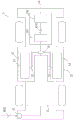
FIG. 2 is a schematic diagram of a power supply system of an electric vehicle according to a preferred embodiment of the invention.
Fig. 3 is a schematic diagram of an architecture of a first switching battery pack according to a preferred embodiment of the invention.
FIG. 4 is a schematic view of the first electrical connection unit and the first electrical connector according to the preferred embodiment of the invention.
Fig. 5 is a schematic external view of a first exchange battery according to another preferred embodiment of the invention.
FIG. 6 is a schematic diagram of a power supply station according to a preferred embodiment of the invention.
Fig. 6A is a schematic diagram of a partial structure of a power supply station according to another embodiment of the invention.
FIG. 7 is a flowchart illustrating a method for maintaining electric power of an electric vehicle according to a preferred embodiment of the present invention.
FIG. 8 is a flowchart illustrating another step of a method for maintaining power of an electric vehicle according to a preferred embodiment of the present invention.
Description of the reference numerals
1 electric vehicle
10 Main Electrical connector
11 main battery pack
111 main casing
113 main battery
12 DC charging socket
13 exchange battery pack accommodating space
14 first exchange battery
141 first casing
142 cell
143 dc power conversion unit
144 first electrical connection unit
1441 first body
1442 first terminal
1443 leading terminal
145 second electrical connection unit
15 first electrical connector
151 holes
16 drive module
161 DC/AC power conversion unit
162 alternating current motor
2 Power supply station
21 exchange battery pack loading and unloading device
211 clamping and bearing mechanism
212 moving mechanism
22 ac/dc power supply conversion device
23 dc/ac power supply converter
24 DC charging device
25 electric power network
26 DC/DC power supply conversion device
AC01 AC driving power supply
AC11 first AC power supply
AC12 second AC power supply
DC01, DC11 first direct current power supply
DC02, DC12 second DC power supply
DC13 third DC power supply
S01-S10 Power sustaining method steps
Detailed Description
This summary is explained below by way of examples, which are not intended to limit the invention to any particular environment, application, or particular manner in which the invention may be practiced as described in the examples. Therefore, the description of the embodiments is for the purpose of illustration only, and not for the purpose of limitation. It should be noted that in the following embodiments and drawings, components not directly related to the present invention are omitted and not shown; the dimensional relationships among the components in the drawings are for ease of understanding only and are not intended to be limiting.
In order to facilitate the charging of the electric vehicle, the invention provides the electric vehicle capable of replacing the exchange battery pack, wherein the electric vehicle can comprise an electric locomotive and an electric vehicle, and the electric vehicle is taken as an example for illustration. Referring to fig. 1, an electric vehicle 1 according to a preferred embodiment of the present invention includes a main electrical connector 10, a main battery pack 11, a dc charging socket 12, a switching battery pack accommodating space 13, and a first switching battery pack 14.
Referring to fig. 2 and fig. 3, the main battery pack 11 at least includes a main housing 111 and two or more main batteries 113 electrically connected to each other, wherein the main batteries 113 are accommodated and fixed in the main housing 111. In the present embodiment, the main battery 11 is disposed in the bottom space between the four wheels of the electric vehicle 1 and is firmly combined with the body structure of the electric vehicle 1 (not shown), but the disposition position of the main battery 11 may vary according to the design of each vehicle type.
The main electrical connector 10 is electrically connected to the main battery pack 11 to supply and drive an electric power generated by the main battery 113 in the main battery pack 11 to each electrical unit required by the electric vehicle 1. The DC charging socket 12 is also electrically connected to the main battery pack 11, receives a first DC power DC01 transmitted from the outside, and transmits a first DC power DC01 to each of the main batteries 113 to charge the main batteries. In other words, the main electrical connector 10 includes a receiving circuit and an output circuit.
The first exchange battery pack 14 has a different shape from the main battery pack 11, and is disposed in the exchange battery pack accommodating space 13. The exchange battery receiving space 13 may be any open space in the body of the electric vehicle 1, or a semi-closed space or a closed space (not shown) specially designed for an exchange battery compartment, which is not limited herein. The first switching battery pack 14 is electrically connected to a first electrical connector 15, and the first electrical connector 15 is electrically connected to the main electrical connector 10, so that a second DC power DC02 outputted from the first switching battery pack 14 is transmitted to the main battery pack 11 through the first electrical connector 15 and the main electrical connector 10, and charges the main battery 113 of the main battery pack 11. It should be noted that the number of the first exchange battery packs 14 can be designed according to actual requirements, in this embodiment, the electric vehicle 1 can be configured with two first exchange battery packs 14 as an example, in other words, the electric vehicle 1 has two exchange battery pack accommodating spaces.
The first exchange battery pack 14 has a first casing 141, two or more batteries 142, a dc power conversion unit 143, and a first electrical connection unit 144. The battery 142 and the dc power conversion unit 143 are electrically connected to each other and accommodated in the first casing 141, and the first electrical connection unit 144 is connected to the first casing 141 and passes through the first casing 141 to be electrically connected to the dc power conversion unit 143. Referring to fig. 4, the first electrical connection unit 144 has a first body 1441 and a first terminal 1442. The first body 1441 is connected to the first housing 141 and covers at least a portion of the first terminal 1442. Specifically, one end of the first terminal 1442 passes through the first body 1441 and penetrates through the first housing 141 to be electrically connected to the dc power conversion unit 143, and the other end of the first terminal 1442 is exposed out of the first housing 141 and the first body 1441 for being electrically connected to the first electrical connector 15.
As shown in fig. 1, in the present embodiment, the electric vehicle 1 further includes a driving module 16 electrically connected to the main battery 11. The driving module 16 receives a power supplied from the master battery pack 11 to drive the electric vehicle 1. The driving module 16 includes a dc/ac power conversion unit (Inverter)161 and an ac motor 162. The dc/AC power converting unit 161 receives the power supplied from the main battery pack 11 and converts it into an AC driving power AC01 to supply to the AC motor 162. The AC motor 162 operates according to the AC driving power AC01 and drives the wheels to rotate, so as to drive the electric vehicle 1.
It should be noted that the first exchange battery pack 14 has a certain weight (about 50 kg to 150 kg), and when the first exchange battery pack 14 is placed in the exchange battery pack accommodating space 13 and the first electrical connection unit 144 is electrically connected to the first electrical connector 15, some mechanisms are needed to connect the first exchange battery pack 14 to the first electrical connector 15 safely and conveniently.
Referring to fig. 4, the first body 1441 of the first electrical connection unit 144 and the first housing 141 are connected in a floating manner, in other words, the first body 1441 and the first terminal 1442 can slightly move up, down, left, and right relative to the first housing 141. In addition, the first electrical connection unit 144 further has two guiding terminals 1443 respectively disposed at two sides of the first body 1441, and the front ends of the guiding terminals 1443 are tapered or spherical, and the first electrical connector 15 also has holes 151 opposite to the guiding terminals 1443. When the first exchange battery 14 is placed in the exchange battery accommodating space 13, the first electrical connection unit 144 moves toward the first electrical connector 15, and the guiding terminal 1443 enters the hole 151, so that the first body 1441 and the first terminal 1442 are combined with the first electrical connector 15 to achieve the electrical connection purpose. It should be noted that when the first exchange battery 14 is slightly shifted in the exchange battery accommodating space 13, the position thereof can be corrected by the guide terminals 1443 and the floating structure.
Furthermore, in order to further secure the position of the first exchange battery pack 14, a rail (not shown) may be disposed in the exchange battery pack accommodating space 13, so that the first exchange battery pack moves along the rail without being easily deviated. In addition, the exchange battery receiving space 13 may have a fixing structure (not shown) therein to enable the first exchange battery 14 to be stably received in the exchange battery receiving space 13, for example, in a locking or fastening manner, which is not limited herein.
In the present embodiment, the electric vehicle 1 has two exchange battery pack accommodating spaces 13 for accommodating the first exchange battery packs 14, respectively, and the exchange battery packs are placed along the rails from two sides of the vehicle body and then fixed by the fastening mechanism.
In addition, referring to fig. 5 again, the first exchange battery pack 14 may further have a second electrical connection unit 145. The second electrical connection unit 145 may be disposed on the other side of the first casing 141 opposite to the first electrical connection unit 144. The second electrical connection unit 145 may be the same structure as the first electrical connector 15, and may be used to connect with a first electrical connection unit of a second exchange battery set, so that the first exchange battery set 14 and the second exchange battery set form an electrical series connection structure.
It should be noted that, under normal conditions, the output power of the master battery pack is greater than that of the exchange battery pack, so that the master battery pack can meet the requirement of providing instantaneous high-power load, and therefore, the electric vehicle 1 is mainly powered by the master battery pack 11, or the first exchange battery pack 14 cooperates with the master battery pack 11 to provide power to drive the electric vehicle 1 to run when the load of the electric vehicle 1 is too large. When the load of the electric vehicle 1 is small, the main battery pack 11 is charged by the first exchange battery pack 14 to maintain the power of the main battery pack 11. However, when the first exchange battery pack 14 also runs out of power, it must be replaced, and the electric vehicle 1 can travel nearby to a power supply station to replace the exchange battery pack. Next, please refer to fig. 6 in combination with the above description, which is a schematic structural diagram of the power supply station 2 according to the preferred embodiment of the present invention.
The power supply station 2 can provide the electric vehicle 1 as described above for the power maintenance work. The power maintenance work is to maintain the power of the main battery pack 11, and therefore, the main battery pack 11 can be directly charged through the dc charging socket 12, and the main battery pack 11 can be charged again by replacing the exchange battery pack depleted in power with the exchange battery pack charged with full power.
The power supply station 2 stores more than two exchange battery packs and at least comprises an exchange battery pack loading and unloading device 21, an alternating current/direct current power supply conversion device 22, a direct current/alternating current power supply conversion device 23 and a direct current charging device 24.
The exchange battery pack loading and unloading device 21 is used for unloading the first exchange battery pack 14 from the electric vehicle 1, and then loading a second exchange battery pack from each stored exchange battery pack to the electric vehicle 1 through the exchange battery pack loading and unloading device 21. In the present embodiment, the exchange battery pack loading and unloading device 21 includes, for example, a clamping and carrying mechanism 211 and a moving mechanism 212. The gripping and supporting mechanism 211 can hold the exchange battery pack and draw out the exchange battery pack from the electric vehicle 1 or load the exchange battery pack to the electric vehicle 1. The moving mechanism 212 can drive the exchange battery pack loading and unloading device 21 to move between the storage position of the exchange battery pack and the electric vehicle 1. In addition, because the weight of the exchange battery pack is about 50 kg to 150 kg, compared with the weight of the main battery pack which is 250 kg to 600 kg, partial manpower can be input to replace the full-automatic replacement equipment during the replacement operation, so the cost expenditure of the full-automatic equipment can be reduced.
The AC/DC power conversion device 22 outputs a first DC power DC11 according to a first AC power AC11 to provide the first exchange battery pack 14 with power exhaustion for charging process. The first AC power source AC11 may be commercial power obtained from the power grid 25.
A number of exchange battery packs are stored in the power supply station 2, and the power supply station 2 can utilize the charged exchange battery packs during peak times of power consumption. In the present embodiment, after the first exchange battery pack 14 is charged, the dc/ac power conversion device 23 can be electrically connected, and the dc/ac power conversion device 23 is electrically connected to the power grid 25. The DC/AC power conversion device 23 converts a second DC power DC12 output from the first switching battery pack 14 into a second AC power AC12 and outputs the second AC power AC12 to the power grid 25. In other words, the power supply station 2 can feed back the power generated by the dc/ac power conversion device 23 to the power grid, which is equivalent to selling the power to the electric power company. In addition, each of the switching battery packs for generating the second AC power AC12 to be output to the power grid may use a switching battery pack that has deteriorated. For example, when fully charged, the exchange battery pack is only 80% or less of the rated capacity, which is not suitable for being mounted on an electric vehicle and reused.
The DC charging device 24 is electrically connected to the DC charging socket 12 of the electric vehicle 1, and outputs a third DC power DC13 to provide the main battery pack 11 of the electric vehicle 1 for fast charging. The DC charging device 24 conforms to at least one specification including but not limited to CHAdemo, GB/T20234, SAE J1772Combo and IEC 62196 Combo.
In the present embodiment, the power source of the DC charging device 24 may be the first DC power DC11 output by the ac/DC power conversion device 22. In other embodiments, as shown in fig. 6A, the power source of the dc charging device 24 may be a dc/dc power conversion device 26. The DC/DC power conversion device 26 can be electrically connected to the charged first switching battery pack 14 and the DC charging device 24, respectively, and convert the second DC power DC12 output by the first switching battery pack into the first DC power DC11 required by the DC charging device 24. Finally, the DC charging device 24 generates a third DC power DC13 according to the first DC power DC11, and outputs the third DC power DC13 to the electric vehicle 1.
Next, referring to fig. 7, a method for maintaining electric power of an electric vehicle according to a preferred embodiment of the invention is described from the perspective of an electric vehicle. As shown in fig. 7, the power maintaining method of the electric vehicle includes the following steps.
Step S01: a master battery pack provides energy to drive a first electric vehicle to move to a first power supply station. The energy provided by the main battery pack drives the electric vehicle through an Output voltage bus (Output voltage bus).
Step S02: and loading a first exchange battery pack on the first electric vehicle at the first power supply station, so that the first exchange battery pack is electrically connected with the main battery pack to charge the main battery pack of the first electric vehicle.
Step S03: when the first exchange battery pack is loaded, the first power supply station is electrically connected with the main battery pack through a direct current charging device so as to charge the main battery pack. The DC charging device charges the master battery pack according to at least one specification including but not limited to CHAdemo, GB/T20234, SAE J1772Combo and IEC 62196 Combo. And the current for charging the main battery pack by the direct current charging device is more than 3 times of the nominal capacity of the main battery pack.
Step S04: when the first exchange battery pack is loaded on the first electric vehicle, the main battery pack provides power to drive the first electric vehicle to move to a second power supply station.
Step S05: and unloading the first exchange battery pack from the first electric vehicle at the second power supply station.
Step S06: and loading a second exchange battery pack on the first electric vehicle at the second power supply station so that the second exchange battery pack is electrically connected with the main battery pack to charge the main battery pack of the first electric vehicle. The first exchange battery pack and the second exchange battery pack have the same shape but different capacities.
Step S07: and when the first exchange battery pack is unloaded and the second exchange battery pack is loaded, the second power supply station is electrically connected with the main battery pack through a direct current charging device so as to charge the main battery pack. As described above, the DC charging device charges the master battery pack according to at least one specification including, but not limited to, CHAdemo, GB/T20234, SAE J1772Combo, and IEC 62196 Combo. And the current for charging the main battery pack by the direct current charging device is more than 3 times of the nominal capacity of the main battery pack.
Step S08: when the second exchange battery pack is loaded, the main battery pack provides energy to drive the first electric vehicle away from the second power supply station. In this embodiment, the first power supply station and the second power supply station may be the same power supply station or different power supply stations, which is not limited herein.
In summary, the electric vehicle mainly uses the main battery pack to provide energy to drive the electric vehicle to move, and the exchange battery pack mainly charges the main battery pack, when the electric power consumption of the main battery pack and the exchange battery pack reaches a certain low level, the electric vehicle can be nearby to the electric power supply station to replace the exchange battery pack, so as to maintain the electric quantity level of the main battery pack. In addition, when the electric vehicle is replacing the exchange battery pack, the power supply station can charge the main battery pack by using the direct current charging device at the same time. Therefore, the situation that the main battery pack is still in a low-power state and cannot provide instant high power when the electric vehicle needs instant high-power output after the exchange battery pack is replaced can be avoided.
Referring to fig. 8, the method for maintaining the electric power of the electric vehicle will be described by following the above steps from the perspective of the power supply station. As shown in fig. 8, the power maintaining method further includes the following steps.
Step S09: and charging the first exchange battery pack unloaded by the first electric vehicle at the second power supply station. In this embodiment, the first exchange battery pack has a dc power conversion unit (Converter) and two or more batteries electrically connected to each other, and a dc charging device of the second power supply station is electrically connected to the dc power conversion unit and charges each of the batteries through the dc power conversion unit. In another embodiment, the charging device of the second power supply station is directly electrically connected to each battery and directly charges each battery. In other words, according to actual needs, the charging operation of the charging device to the exchange battery pack can be performed by charging each battery through the dc power conversion unit, or by directly charging each battery without the dc power conversion unit.
Step S10 is to load the charged first swap battery assembly on a second electric vehicle at the second power supply station. So that the first exchange battery set is electrically connected with the main battery set of the second electric vehicle to charge the main battery set of the second electric vehicle.
In summary, for the electric vehicle, the electric vehicle can receive the exchange battery packs with different brands and capacities to charge the main battery pack, and the used exchange battery pack can be provided for the electric vehicles with different brands and models after being charged. The running distance and the service time of the electric vehicle can be prolonged by charging the main battery pack through the exchange battery pack. In terms of the power supply station, the power supply station can provide an operation space for replacing the exchange battery pack of the electric vehicle, and the power supply station can utilize the direct current charging device to charge the main battery pack on a basic basis while replacing the exchange battery pack, so that the main battery pack can maintain a certain degree of energy, and the service life of the main battery pack can be prolonged. In addition, the power supply station can provide power for the electric vehicle, exchange power through the stored exchange battery pack, convert the direct current power into the alternating current power, and transmit the alternating current power to the power grid to be sold to the electric power company.
The above examples are provided for clarity of illustration only and are not intended to limit the invention to the particular embodiments described. Other variations and modifications will be apparent to persons skilled in the art in light of the above description. And are neither required nor exhaustive of all embodiments. Any obvious variations or modifications which come within the spirit and scope of the invention are desired to be protected by the following claims.

Claims (10)

1. An electric power maintaining method for an electric vehicle, which is applied in cooperation with at least a first electric vehicle, a second electric vehicle, a first electric power supply station and a second electric power supply station, wherein the first electric vehicle and the second electric vehicle respectively have a main battery pack and at least one exchange battery pack accommodating space, the main battery pack is firmly combined with a body structure of the first electric vehicle or the second electric vehicle to which the main battery pack belongs, an electric connector is arranged in the exchange battery pack accommodating space, so that the exchange battery pack arranged in the exchange battery pack accommodating space is electrically connected with the main battery pack, the first electric power supply station and the second electric power supply station respectively have an exchange battery pack loading and unloading device and a direct current charging device, and respectively can provide a plurality of exchange battery packs, the method comprising:
at a first power supply station, a first exchange battery pack with a direct-current power supply conversion unit and more than two batteries is loaded in an exchange battery pack accommodating space of a first electric vehicle through the exchange battery pack loading and unloading device, so that the first exchange battery pack is electrically connected with a main battery pack of the first electric vehicle, wherein the first exchange battery pack charges the main battery pack through the direct-current power supply conversion unit, and the appearance of the main battery pack is different from that of the first exchange battery pack;
at the second power supply station, unloading the first exchange battery pack together with the DC power conversion unit from the first electric vehicle through the exchange battery pack loading and unloading device;
loading a second exchange battery assembly with a direct-current power supply conversion unit and more than two batteries on the first electric vehicle, wherein the first exchange battery assembly and the second exchange battery assembly have the same shape but different capacities; and
and loading the charged first exchange battery pack on a second electric vehicle, wherein the capacity of a main battery pack of the second electric vehicle is different from that of the main battery pack of the first electric vehicle.
2. The power maintenance method of claim 1, further comprising:
in the second power supply station, the dc charging device is electrically connected to the dc power conversion unit of the first exchange battery pack, and each battery of the first exchange battery pack unloaded from the first electric vehicle is charged through the dc power conversion unit.
3. The power maintenance method according to claim 1, wherein the current for charging the master battery pack by the direct-current charging device is greater than 3 times a nominal capacity of the master battery pack.
4. The power maintaining method of claim 1, wherein loading the second exchange battery pack on the first electric vehicle further comprises:
electrically connecting the second exchange battery pack with the master battery pack of the first electric vehicle; and
charging the master battery pack with the second exchange battery pack.
5. The power maintaining method according to claim 1, wherein the output power of the master battery pack is larger than the output power of the first exchange battery pack.
6. The power maintenance method according to claim 1, wherein the main battery pack is connected to the dc charging device through a dc charging socket to charge the main battery pack when the first exchange battery pack is replaced.
7. The power maintenance method of claim 1, wherein the first exchange battery pack provides power in cooperation with the master battery pack to drive the first electric vehicle or the second electric vehicle to travel.
8. The power maintenance method of claim 1, wherein the first electric vehicle is driven by only providing energy from the main battery pack before reaching the first power supply station, and moves to the first power supply station to recharge the first exchange battery pack.
9. An electric power maintaining method for an electric vehicle, at least used in cooperation with a first electric vehicle, a second electric vehicle, a first electric power supply station and a second electric power supply station, wherein the first electric vehicle and the second electric vehicle respectively have a main battery pack and at least one exchange battery pack accommodating space, the main battery pack is firmly combined with a vehicle body structure of the first electric vehicle or the second electric vehicle to which the main battery pack belongs, and the exchange battery pack arranged in the exchange battery pack accommodating space is electrically connected with the main battery pack, the first electric power supply station and the second electric power supply station respectively have an exchange battery pack loading and unloading device and a direct current charging device, and respectively can provide a plurality of exchange battery packs, the method is characterized by comprising the following steps:
at a first power supply station, a first exchange battery pack with a direct-current power supply conversion unit and more than two batteries is loaded in an exchange battery pack accommodating space of a first electric vehicle through the exchange battery pack loading and unloading device, so that the first exchange battery pack is electrically connected with a main battery pack of the first electric vehicle, wherein the first exchange battery pack charges the main battery pack through the direct-current power supply conversion unit, and the appearance of the main battery pack is different from that of the first exchange battery pack;
at the second power supply station, unloading the first exchange battery pack together with the DC power conversion unit from the first electric vehicle through the exchange battery pack loading and unloading device;
loading a second exchange battery assembly with a direct-current power supply conversion unit and more than two batteries on the first electric vehicle, wherein the first exchange battery assembly and the second exchange battery assembly have the same shape but different capacities; and
and loading the charged first exchange battery pack on a second electric vehicle, wherein the capacity of a main battery pack of the second electric vehicle is different from that of the main battery pack of the first electric vehicle.
10. The method of claim 9, wherein the first electric vehicle is driven by only providing energy from the main battery pack before reaching the first power supply station, and moves to the first power supply station to recharge the first battery pack.
CN202010668878.8A 2014-09-02 2014-09-02 Electric power maintaining method for electric vehicle Active CN112026552B (en)

Priority Applications (1)

Application Number Priority Date Filing Date Title
CN202010668878.8A CN112026552B (en) 2014-09-02 2014-09-02 Electric power maintaining method for electric vehicle

Applications Claiming Priority (2)

Application Number Priority Date Filing Date Title
CN202010668878.8A CN112026552B (en) 2014-09-02 2014-09-02 Electric power maintaining method for electric vehicle
CN201410442887.XA CN105437987B (en) 2014-09-02 2014-09-02 Electric vehicle, power supply station, and electric power maintaining method for electric vehicle

Related Parent Applications (1)

Application Number Title Priority Date Filing Date
CN201410442887.XA Division CN105437987B (en) 2014-09-02 2014-09-02 Electric vehicle, power supply station, and electric power maintaining method for electric vehicle

Publications (2)

Publication Number Publication Date
CN112026552A CN112026552A (en) 2020-12-04
CN112026552B true CN112026552B (en) 2021-10-01

Family

ID=55439116

Family Applications (3)

Application Number Title Priority Date Filing Date
CN201410442887.XA Active CN105437987B (en) 2014-09-02 2014-09-02 Electric vehicle, power supply station, and electric power maintaining method for electric vehicle
CN202010668878.8A Active CN112026552B (en) 2014-09-02 2014-09-02 Electric power maintaining method for electric vehicle
CN202010669725.5A Active CN111976507B (en) 2014-09-02 2014-09-02 Electric vehicle with exchange battery group

Family Applications Before (1)

Application Number Title Priority Date Filing Date
CN201410442887.XA Active CN105437987B (en) 2014-09-02 2014-09-02 Electric vehicle, power supply station, and electric power maintaining method for electric vehicle

Family Applications After (1)

Application Number Title Priority Date Filing Date
CN202010669725.5A Active CN111976507B (en) 2014-09-02 2014-09-02 Electric vehicle with exchange battery group

Country Status (5)

Country Link
US (1) US10464431B2 (en)
JP (1) JP6464259B2 (en)
CN (3) CN105437987B (en)
TW (1) TWI620393B (en)
WO (1) WO2016034050A1 (en)

Families Citing this family (18)

* Cited by examiner, † Cited by third party
Publication number Priority date Publication date Assignee Title
US20170282734A1 (en) * 2016-04-04 2017-10-05 Skycatch, Inc. Unmanned aerial vehicle self-aligning battery assembly
US20170346322A1 (en) * 2016-05-28 2017-11-30 Shihab Kuran Transportable electrical energy storage and supply system
DE102016219940A1 (en) * 2016-10-13 2018-04-19 Volkswagen Aktiengesellschaft Intelligent charging communication switching in CAN-based charging systems
CN116788073A (en) 2017-01-05 2023-09-22 通用电气公司 DC charging circuit and DC charging station for electric vehicle
WO2019018679A1 (en) * 2017-07-19 2019-01-24 Ford Global Technologies, Llc Swappable battery system
US10842473B2 (en) 2017-10-30 2020-11-24 Ethicon Llc Surgical instrument having dual rotatable members to effect different types of end effector movement
US10932804B2 (en) 2017-10-30 2021-03-02 Ethicon Llc Surgical instrument with sensor and/or control systems
US11129634B2 (en) 2017-10-30 2021-09-28 Cilag Gmbh International Surgical instrument with rotary drive selectively actuating multiple end effector functions
CN109515395B (en) * 2017-12-13 2022-05-03 蔚来(安徽)控股有限公司 Battery changing actuating mechanism
JP2019145088A (en) 2017-12-29 2019-08-29 ゴゴロ インク System and method for dynamically distributing energy between exchangeable energy storage device stations
WO2021071412A1 (en) * 2019-10-08 2021-04-15 Sten Corfitsen Electric vehicle with modular battery system
CN111199374B (en) * 2019-12-31 2023-07-21 河南云煤网网络科技有限责任公司 Method and system for identifying, metering and settling identity of goods entering and exiting factory
CN112421739B (en) * 2020-04-24 2024-01-02 葛炽昌 Alternating-current charging system of electric vehicle
JP7218071B2 (en) * 2020-08-19 2023-02-06 矢崎総業株式会社 power supply
CN112510735B (en) * 2020-09-24 2023-06-20 葛炽昌 Power dispatching system and power dispatching method
DE102022112585B3 (en) 2022-05-19 2023-09-14 Next.E.Go Mobile SE BATTERY FOR A MOTOR VEHICLE AND MOTOR VEHICLE
DE102022112582A1 (en) 2022-05-19 2023-11-23 Next.E.Go Mobile SE BATTERY FOR A MOTOR VEHICLE, MOTOR VEHICLE AND METHOD FOR CHARGING SUCH A BATTERY
US11775872B1 (en) 2022-12-01 2023-10-03 Recentive Analytics, Inc. Techniques for identifying optimal EV charging station locations

Family Cites Families (66)

* Cited by examiner, † Cited by third party
Publication number Priority date Publication date Assignee Title
US4477764A (en) * 1982-07-15 1984-10-16 Pollard Earsel W Energy generating and storage system for electric vehicle or the like
US5157319A (en) * 1991-09-27 1992-10-20 Electric Power Research Institute Contactless battery charging system
US5373910A (en) * 1993-04-08 1994-12-20 Nixon; Dale B. Method of operation for an electric vehicle having multiple replacement batteries
JPH07123514A (en) * 1993-10-19 1995-05-12 Hitachi Ltd Electric vehicle and running control method therefor
US5549443A (en) * 1994-01-06 1996-08-27 Hammerslag; Julius G. Battery charging and transfer system
US5612606A (en) * 1994-09-15 1997-03-18 David C. Guimarin Battery exchange system for electric vehicles
JP3617183B2 (en) * 1996-05-08 2005-02-02 トヨタ自動車株式会社 Electric vehicle power supply
DE19621668A1 (en) * 1996-05-30 1997-12-04 Uwe Kochanneck Multi=block robot system e.g. for logistics and power supply to electric vehicles
JPH1086678A (en) * 1996-09-17 1998-04-07 Nippon Home Keizai Kenkyusho:Kk Electric vehicle
TW494071B (en) * 1998-10-29 2002-07-11 Ling-Yuan Tzeng Composite motor vehicle battery
JP2001057711A (en) * 1999-01-25 2001-02-27 Zip Charge:Kk Energy supply system for electric vehicle, battery for electric vehicle, battery charger for the electric vehicle, battery vending apparatus and battery managing system for the electric vehicle
US20030209375A1 (en) * 1999-01-25 2003-11-13 Zip Charge Corporation Electrical vehicle energy supply system, electrical vehicle battery, electrical vehicle battery charging apparatus, battery supply apparatus, and electrical vehicle battery management system
US7520355B2 (en) * 2000-07-06 2009-04-21 Chaney George T Hybrid electric vehicle chassis with removable battery module
FR2819759B1 (en) * 2001-01-24 2003-05-23 Alstom POWER SUPPLY SYSTEM FOR AN ELECTRICALLY DRIVEN VEHICLE
US20030070850A1 (en) * 2001-02-16 2003-04-17 Cellex Power Products, Inc. Hybrid power supply apparatus for battery replacement applications
US20030227275A1 (en) * 2002-03-29 2003-12-11 Takashi Kishi Battery pack and battery pack with AC/DC conversion circuit board
JP3881317B2 (en) * 2003-01-30 2007-02-14 川崎重工業株式会社 Battery box for railway vehicles
JP2004364481A (en) * 2003-06-05 2004-12-24 Yoji Makishima Storage battery for electric automobile equipped with semiconductor integrated circuit
CN1261319C (en) * 2004-11-11 2006-06-28 北京电巴科技有限公司 Electric public transport system
US7602143B2 (en) * 2005-11-04 2009-10-13 Peter David Capizzo System for replenishing energy sources onboard different types of automotive vehicles
JP2008079435A (en) * 2006-09-21 2008-04-03 Mitsubishi Fuso Truck & Bus Corp Electric vehicle
CN101224711A (en) * 2007-01-19 2008-07-23 王春 Electric motorcar
JP4731607B2 (en) * 2007-02-19 2011-07-27 株式会社エネルギー応用技術研究所 Power supply device for quick charge and power supply method for quick charge
US20080294283A1 (en) * 2007-05-25 2008-11-27 Ronald Ligrano Battery exchange station and a method of changing therein
US20090058355A1 (en) * 2007-08-29 2009-03-05 Meyer Keith M Electric vehicle battery module and replacement system
JP4277928B1 (en) * 2007-12-07 2009-06-10 トヨタ自動車株式会社 vehicle
JP4577413B2 (en) * 2008-06-20 2010-11-10 トヨタ自動車株式会社 vehicle
US7993155B2 (en) * 2008-09-19 2011-08-09 Better Place GmbH System for electrically connecting batteries to electric vehicles
JP5509577B2 (en) * 2008-10-31 2014-06-04 日本電気株式会社 Charging device, management device, battery system, battery management method, and battery management program
US8146694B2 (en) * 2009-01-20 2012-04-03 Vahid Hamidi Swappable modulated battery packs system for electrically driven vehicle
CN101879899B (en) * 2009-09-04 2013-05-22 上海安骏能环保科技有限公司 Classification drive battery system
US8629657B2 (en) * 2009-12-31 2014-01-14 Tesla Motors, Inc. State of charge range
US20110184903A1 (en) * 2010-01-26 2011-07-28 Liam-Yung Sung Operation System For Providing Backup Batteries For Hybrid Vehicles And/Or Electric Vehicles And Method Thereof
JP5520064B2 (en) * 2010-01-27 2014-06-11 三洋電機株式会社 Battery system
JP2011205755A (en) * 2010-03-25 2011-10-13 Toyota Motor Corp Charging device
US8820444B2 (en) * 2010-04-16 2014-09-02 Tuan Nguyen Electric vehicle having exchangeable battery modules and method of resupply therefor
JP5618359B2 (en) * 2010-08-02 2014-11-05 Necエナジーデバイス株式会社 Secondary battery pack connection control method and power storage system
CN201766113U (en) * 2010-09-13 2011-03-16 天津市捷威动力工业有限公司 Electric automobile and power battery pack therefor
JP5474737B2 (en) * 2010-11-11 2014-04-16 本田技研工業株式会社 Saddle riding type electric vehicle
JP5261838B2 (en) * 2010-12-03 2013-08-14 本田技研工業株式会社 Electric vehicle control device
US8853883B2 (en) * 2010-12-29 2014-10-07 Caterpillar Inc. System and methods for starting a prime mover of a power system
JP2012145499A (en) * 2011-01-13 2012-08-02 Jsol Corp Guide system
CN102152776B (en) * 2011-03-07 2013-10-09 国电南瑞科技股份有限公司 Battery replacing system and battery replacing method of electromobile battery replacing station
JP5273187B2 (en) * 2011-03-15 2013-08-28 株式会社豊田自動織機 Vehicle battery exchange device
CN201970973U (en) 2011-03-23 2011-09-14 北京理工华创电动车技术有限公司 Fast pure electric vehicle power battery replacement station
JP5728270B2 (en) * 2011-03-31 2015-06-03 富士重工業株式会社 Charging system
US9123035B2 (en) * 2011-04-22 2015-09-01 Angel A. Penilla Electric vehicle (EV) range extending charge systems, distributed networks of charge kiosks, and charge locating mobile apps
US9285944B1 (en) * 2011-04-22 2016-03-15 Angel A. Penilla Methods and systems for defining custom vehicle user interface configurations and cloud services for managing applications for the user interface and learned setting functions
US10217160B2 (en) * 2012-04-22 2019-02-26 Emerging Automotive, Llc Methods and systems for processing charge availability and route paths for obtaining charge for electric vehicles
US8963481B2 (en) * 2011-05-25 2015-02-24 Green Charge Networks Charging service vehicles and methods using modular batteries
JP5278512B2 (en) * 2011-08-10 2013-09-04 トヨタ自動車株式会社 vehicle
US20130080254A1 (en) * 2011-09-21 2013-03-28 Jeff Thramann Electric Vehicle Charging Station with Connectivity to Mobile Devices to Provide Local Information
US9997753B2 (en) * 2011-10-11 2018-06-12 Toyota Jidosha Kabushiki Kaisha Mounting structure for electric storage apparatus
JP5710783B2 (en) * 2011-12-08 2015-04-30 株式会社エネルギー応用技術研究所 Power supply system for quick charging
CN102490622A (en) * 2011-12-19 2012-06-13 青岛威能电动车辆电控有限公司 Power supply control method for auxiliary system of electric automobile
EP2614982A3 (en) * 2012-01-11 2017-11-01 Tata Technologies Pte Ltd Swappable, configurable and structural battery pack for electric vehicles
JP2013150497A (en) * 2012-01-23 2013-08-01 Toyota Motor Corp Electric vehicle
EP3269585B1 (en) * 2012-05-09 2023-03-01 Toyota Jidosha Kabushiki Kaisha Vehicle comprising contactless power reception unit
JP5641024B2 (en) * 2012-08-07 2014-12-17 トヨタ自動車株式会社 Battery management system and battery replacement method
WO2014063065A1 (en) * 2012-10-19 2014-04-24 Gogoro, Inc. Battery configuration for an electric vehicle
KR20140060633A (en) * 2012-11-12 2014-05-21 주식회사 엘지화학 Battery module having bus bar assembly and battery pack comprising the same
FR3008041B1 (en) * 2013-07-05 2016-12-09 Blue Solutions ELECTRIC VEHICLE AND ASSOCIATED TRANSPORT FACILITY
US9358895B2 (en) * 2013-10-28 2016-06-07 Meir Avganim Quick loading and unloading battery system for vehicles
KR101542664B1 (en) * 2013-12-03 2015-08-12 강병혁 Battery pack of elecctric vehicle changing System with energy storage system
CN105846479B (en) * 2015-01-13 2019-01-25 葛炽昌 Communicating battery group and its control method applied to electric vehicle
US10293698B2 (en) * 2015-08-10 2019-05-21 Ford Global Technologies, Llc System and method for powering electrified vehicle with modular battery

Also Published As

Publication number Publication date
TWI620393B (en) 2018-04-01
WO2016034050A1 (en) 2016-03-10
CN105437987B (en) 2020-10-13
JP6464259B2 (en) 2019-02-06
TW201611468A (en) 2016-03-16
CN111976507A (en) 2020-11-24
CN105437987A (en) 2016-03-30
CN111976507B (en) 2021-12-24
US10464431B2 (en) 2019-11-05
CN112026552A (en) 2020-12-04
JP2017529039A (en) 2017-09-28
US20170253138A1 (en) 2017-09-07

Similar Documents

Publication Publication Date Title
CN112026552B (en) Electric power maintaining method for electric vehicle
US9840137B2 (en) Electrically-driven vehicle
US8307930B2 (en) Scalable, hybrid energy storage for plug-in vehicles
JP5373999B2 (en) Hybrid storage battery, traveling vehicle and power storage facility using the same, smart grid traveling vehicle system using the traveling vehicle, and power supply network system using the power storage facility
US20230231395A1 (en) Battery system
CN107078535B (en) Multi-accumulator system for an on-board electrical system of a motor vehicle
US11362524B2 (en) Battery system and a method for use in the battery system
US20130293005A1 (en) Electric motor vehicle and redox flow module and cartridge therefor
KR20110137675A (en) Charge station
CN102602301B (en) A kind of electric system for fuel cell hybrid vehicle
KR20150109608A (en) Apparatus for charging electric vehicle
KR101331000B1 (en) Battery for electric vehicle
CN109050256A (en) Electric car auxiliary power unit
CN210760705U (en) Mobile exchange charging station
WO2022013664A1 (en) Electrically driven motorised vehicle with rechargeable battery and trolley provided therewith
CN103151476A (en) Power supply module and electromobile provided with same
CN202896269U (en) Range-extending hybrid power system
CN210669625U (en) Power supply system conversion circuit for commercial vehicle
KR101492892B1 (en) Ultra-capacitor pack applied to hybrid energy storage devices
CN207389023U (en) Possesses the electric drive accumulation power supply vehicle of automatic moving ability
IT202100001031U1 (en) Modular portable/transportable and autonomous battery charger, for fast charging of electric vehicles (BEV, PHEV, small boats, electric buses)
Rakshitha et al. Algorithm Controlled Battery Management System in Electric Vehicles
CN114248636A (en) Electric system with universal battery, electric vehicle and power supply method
KR20240011416A (en) Carrier type auxiliary battery for electric car
CN114013301A (en) Bus with double-path energy supply and energy supply method

Legal Events

Date Code Title Description
PB01 Publication
PB01 Publication
SE01 Entry into force of request for substantive examination
GR01 Patent grant
GR01 Patent grant