CN1116844A - Container ship unloader with anti-sway device - Google Patents
Container ship unloader with anti-sway device Download PDFInfo
- Publication number
- CN1116844A CN1116844A CN94191010.5A CN94191010A CN1116844A CN 1116844 A CN1116844 A CN 1116844A CN 94191010 A CN94191010 A CN 94191010A CN 1116844 A CN1116844 A CN 1116844A
- Authority
- CN
- China
- Prior art keywords
- trolley
- freight container
- blade
- trusses
- mentioned
- Prior art date
- Legal status (The legal status is an assumption and is not a legal conclusion. Google has not performed a legal analysis and makes no representation as to the accuracy of the status listed.)
- Pending
Links
Images


Classifications
-
- B—PERFORMING OPERATIONS; TRANSPORTING
- B66—HOISTING; LIFTING; HAULING
- B66C—CRANES; LOAD-ENGAGING ELEMENTS OR DEVICES FOR CRANES, CAPSTANS, WINCHES, OR TACKLES
- B66C19/00—Cranes comprising trolleys or crabs running on fixed or movable bridges or gantries
- B66C19/002—Container cranes
-
- B—PERFORMING OPERATIONS; TRANSPORTING
- B66—HOISTING; LIFTING; HAULING
- B66C—CRANES; LOAD-ENGAGING ELEMENTS OR DEVICES FOR CRANES, CAPSTANS, WINCHES, OR TACKLES
- B66C13/00—Other constructional features or details
- B66C13/04—Auxiliary devices for controlling movements of suspended loads, or preventing cable slack
- B66C13/06—Auxiliary devices for controlling movements of suspended loads, or preventing cable slack for minimising or preventing longitudinal or transverse swinging of loads
Landscapes
- Engineering & Computer Science (AREA)
- Mechanical Engineering (AREA)
- Ship Loading And Unloading (AREA)
Abstract
The present invention relates to a dockside crane for moving cargo between a dock and a water-borne vessel. The crane has an elongated girder extending over the dock and vessel. The crane can vertically raise and lower the girder so as to minimize distance and travel time for the cargo. A trolley which has a cargo engaging device and two side paddles engages and lifts the cargo. The cargo is held between the paddles to prevent sway during acceleration of the cargo, allowing higher travel speeds. Preferably, an independently movable operator cab is provided, and the paddles preferably extend below the center of gravity of the cargo.
Description
The present invention relates to the apparatus and method for that is used between the different location, transporting cargo.Specifically, the present invention relates to the structure and the operation of the crane that improvement conveys goods between harbour and ship.
In the past few decades, aspect the loading and unloading carriage of goods by sea very big variation has taken place between ship and harbour.The most noticeable improvement is exploitation and has used box ship and container crane.Box ship can load and unload the goods that is encapsulated in the standard rectangular freight container, thereby available equipment with appropriate configuration transports freight container systematically and freight container is stacked so that store and does further the loading and unloading from the three unities to another place.Container crane is the large pier gantry crane that can vertically move at rail upper edge harbour.Such crane generally has a large-scale horizontal trolley crossbeam or a trusses, and this crossbeam or trusses vertically and for good and all are fixed on a certain certain height place and extend to the ship top that is docked in the harbour next door.Along the trolley trusses one packaged type driving or the trolley that is contained on this trusses arranged.Wire rope suspensioning on the trolley on the draw-beam that is also referred to as conveyer, and this draw-beam is designed to and can engages with the corner of cargo-type container by the device that is called stranded lock.People's such as Loomis US Patent the 3749438th has illustrated a kind of device of stranded locking-type.Trolley can move along the trolley trusses.If the part of trolley can pivotally rise and descend so that carry cargo freight container on the whole horizontal throw between harbour and the ship around hinge-point, then this part is called crane arm.Thereby also can vertically promoting or put down freight container along horizontal rail, trolley can walk around any obstacle on the track.
This representative type list trolley formula container crane has some defectives, and one of them defective is that permanent solid trolley trusses must be positioned at sufficiently high position so that can work above the freight container of different size.Because said trusses must be provided with and be fixed on the certain altitude place, so can increase driver's parallax and can increase the distance that described conveyer will be positioned to lift the container position place.Although this single loop wheel machine formula crane be for the horizontal high-speed travel of trolley to accelerate design-calculated duty cycle.But steel rope is suspended in freight container a certain distance of trolley below usually, and this can produce the undesirable phenomenon of waving, thereby can increase production time.
Noticing that other prior arts have used two trolley formula cranes under the circumscribed situation of single trolley formula crane, this crane will be divided into two stages duty cycle in the known mode of fire fighter that is very similar to into team's fortune water.Fire fighter's fortune water is formed into columns can pass to another person with bucket from a people quickly, rather than everybody goes to the scene of fire from the water source respectively.Following patent specification use the example of the harbour of two trolley principles with container crane: No. 3812987 (Watatani), No. 4046265 (Wormmeester etc.) of US Patent, No. 4106639 (Montgomery etc.), No. 4172685 (Nabeshima etc.), No. 4293077 (Makimo) and No. 4599027 (Knapp).
Above-mentioned patent description dissimilar cranes, some of them have been used platform in the middle of the fixed type that has one second trolley, other have then used platform in the middle of the lifting mode.Although platform can be realized higher capacity rating in the middle of utilizing,, with duty cycle separated into two parts can make equipment complicated, thereby make equipment quite expensive.Also need two drivers to handle a two trolley formula crane, this can increase the operating cost of equipment again significantly.
Therefore, an object of the present invention is to provide a kind of harbour crane that has horizontal trolley trusses, said trusses harbour and sitting duck only above extend, above-mentioned crane can lifting so that the trolley trusses is positioned any height place between the high-low limit position, and, above-mentioned crane also has the trolley that can move along above-mentioned trusses, and this trolley then has a conveyer, so that goods is lifted away from harbour and ship or goods is placed on harbour and the ship.
Another object of the present invention is to improve, and by improving, can and be arranged on interval near the ship operation height trolley trusses safety.Therefore, when goods being moved to or moves apart ship, can promote goods apace with conveyer, said conveyer then is stuck on the trolley tightly, thereby, can not have unsteadily along the length direction of trusses and move trolley and cargo with higher acceleration and speed.
Another purpose of the present invention is can make cargo walk around the minimum of any obstacle on the ship may to make harbour reduce to minimum with the vertical hoisting distance of crane by height by the trolley trusses is reduced to.
A further object of the present invention provides a kind of and sentences independent mode at lower height and be contained in operator's compartment on the trolley trusses, and therefore, the driver is in comparatively favourable position when the loading and unloading cargo, thereby can position operation faster, more accurately.
Also purpose of the present invention provides the structure such as the blade that extends to cargo center of gravity below, so that make waving of freight container reduce to minimum and avoid excessively afterburning to hoisting cable, if there is not above-mentioned blade, will have said excessive reinforcing in bigger acceleration or between deceleration period.
Another object of the present invention provides a kind of method, in this method, by simplifying each step in the loading or unloading process, can reduce the time of loading or unloading operation.
The present invention also comprise directly with vertically moving trolley trusses in the relevant method of employed mechanical technique.This method comprises series of steps, by these steps, can be when trolley is loaded and unloaded the stacking goods on the ship the trusses of trolley be positioned certain height.Then, when loading or unloading stacking goods, the trolley trusses can be moved to one second height so that trolley loads and unloads other stacking goods on the ship.In this one side of the present invention, said method generally includes trolley is vertically moved to the such step of certain altitude, said height is substantially equal to following height: (A) make the distance of conveyer between the top of specifying slot on the ship that this bottom of device and the loading and unloading container of wanting near trolley the time are provided reduce to minimum height, perhaps the distance between (B) high obstacle thing of making conveyer hang when being promoted near trolley will to walk around when the bottom of the freight container below this conveyer and freight container specify the container cargo interdigit to move on harbour and ship reduces to minimum height.When the trolley trusses is positioned at the approximate altitude that is determined by these parameters, said trolley just can be between harbour and ship mobile goods.Above-mentioned height is applicable to the freight container that is positioned on the deck, also be applicable to as the cabin loading and unloading container.
By vertical truss device is provided, can be at harbour with realizing above-mentioned and other purpose of the present invention in the hoisting crane, said truss device comprises: be positioned near the supporting structure that is bearing in the harbour waterside on the harbour; The trusses device of lengthening, but this device is installed on the above-mentioned truss device and extend on harbour and the vessel at anchor adjacent with this harbour upper horizontal ground with the water surface of handling goods; Jacking system, this device are used to make above-mentioned trusses vertical lift to change the height of this trusses above harbour and vessel at anchor; The cargo transport device that above-mentioned trusses device is entrained, this device can along this trusses device the upper horizontal of harbour and vessel at anchor move; And goods connecting device, this device by flexible supporting device be suspended in the below of above-mentioned cargo transport device and relatively the goods yard on harbour and the vessel at anchor make vertical lift, wherein, said goods connecting device can rise near the cargo transport device fully and preferably abut in tightly on this cargo transport device, does not make above-mentioned cargo transport device that bigger horizontal acceleration and speed are arranged under the situation of waving so that be not attended by basically at any goods that is transported.
The present invention also provides a kind of device that is used for freight container is moved to fast from start position the final position.This device has at least one trolley that is generally the trusses of level and is arranged to move along above-mentioned at least one trusses.Said trolley comprise at least one pair of relatively to the catcher blade, this defines a catcher space to blade, freight container then can be put into this space, above-mentioned catcher blade has enough length, therefore, when in the space of container lot between the catcher blade during extreme higher position, this catcher blade can extend below the freight container center of gravity, thereby can offset because of quickening or the caused moment that acts on the freight container of slowing down, therefore can stop this freight container to wave basically.
Above-mentioned trolley also comprises the anti-structure of rising and falling of at least one trolley, above-mentioned trusses comprises the anti-structure of rising and falling of at least one trusses, thereby the anti-lifting structure setting of the aforementioned relatively trolley of this structure can be offset the moment that any meeting makes the end of trolley vertically rise along the freight container path, therefore can prevent basically because of quickening or the caused moment that acts on the trolley of slowing down, so can stop this trolley to wave basically.
The present invention also provides a kind of trolley that is used for freight container is transported to from start position the final position.This trolley has: the conveyer that is used for receiver container; Be used to make the device of above-mentioned conveyer and freight container lifting; And at least one pair of relatively to the catcher blade, this extends downward the below of freight container to blade.
In addition, the present invention also provides a kind of method that is used for freight container is moved to from start position the final position.This method has the following step: conveyer is descended to grasp the freight container that is positioned at the start position place; With described conveyer and container lifting at least one pair of relatively to the catcher blade between the position, above-mentioned a pair of blade then departs from each other mutually along the longitudinal path that leads to the final position from start position.Said method also comprises: with higher rate of acceleration conveyer, freight container and catcher blade are quickened, this accelerating step starts from after above-mentioned lifting step finishes basically; And conveyer, freight container and catcher blade are slowed down with higher moderating ratio, so that the top of the position of substantially perpendicularly reaching home.At last, said method comprises that conveyer and freight container are descended to be located so that freight container is placed on the final position.
In addition, the invention provides a kind of being used for freight container is moved to the crane in final position from start position, the structure of this crane comprises: at least one is generally the trusses of level; One can be along the trolley of above-mentioned at least one trusses parallel motion; Be used to grasp the device of freight container; And be used for above-mentioned trolley from the upper horizontal of start position move to the trolley mobile device of top, final position.Have, above-mentioned crane also comprises a bench board again, and this bench board comprises control mechanism so that the driver can control at least: 1) above-mentioned gripping device, 2) above-mentioned trolley mobile device; And 3) movable workbench device, this device are used for moving above-mentioned bench board with the irrelevant mode of trolley motion, thereby the driver can make above-mentioned bench board move so that check trolley from different relative positions and angle relative to trolley.
Fig. 1 is explanation the present invention's the crane structure and the summary side elevation of operation, is positioned at the maximum height place when conveying goods between the upper strata freight container of the trolley trusses of this crane on harbour and ship main deck or is positioned near the maximum height;
Fig. 1 played the summary side elevation of crane machine when Fig. 2 was arranged in minimum altitude or is positioned near the high low clearance during the trolley trusses conveys goods between harbour and ship storehouse;
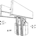
Fig. 3 is the waterside of above-mentioned crane or anterior simplification section-drawing, and this figure has mainly shown the overall structure of trolley and conveyer when the trolley trusses mediates highly;
Fig. 4 is the birds-eye view of a fixed type bottom additional strengthening support and the packaged type platform corner vertical support frame that links thereof;
Fig. 5 be show the goods crane whip along the crane assembly the skeleton diagram in path of process;
Fig. 6 is the transparent view of trolley and conveyer structure, and this structure has been used the collector assembly that is used to stop the distant pendulum of goods;
Fig. 7 is the simplified side view of trolley and conveyor component among Fig. 6;
Fig. 8 A is the transparent view of the trolley of one of the present invention embodiment; Fig. 8 B is the lateral plan of above-mentioned trolley; Fig. 8 C is the end elevation of above-mentioned trolley; Fig. 8 D is identical with Fig. 8 C with Fig. 8 B respectively with Fig. 8 E, but does not show the hidden parts of this embodiment; Fig. 8 F is the enlarged perspective that shows another embodiment of blade, and a catcher shock absorber has been used in the lower end of this blade.
In the process of the most preferred embodiment that the present invention shown in the drawings is described, for clarity sake, used specific term.But the present invention is not limited to selected specific vocabulary, and concerning the step or equipment that realize similar purpose in a similar manner, each specific vocabulary has comprised all terms in the technology equivalence.
At first with reference to the Fig. 1 that draws not in scale, as can be seen, the crane 9 with structure of the present invention is positioned on the harbour 10, and harbour 10 other box ships 11 are docked on the water surface 12.Ship 11 has cargo-type container C, and these freight containers are placed in the horizontal stockpile of stacking,vertical, and stockpile then is positioned on the cabin 14 and the main deck 13 above hatchcover 15 and the deck area of main deck 13 belows.Crane 9 has a vertical main couple assembly 16, and this main couple assembly is provided with four vertical support frames 17, and these bracket supports the bottom additional strengthening supporting component 16A of truss 16.For the purpose of graphic effect,, omitted among the figure and be positioned at support 17A-17B rear and away from two supports 17 of the person with the aid of pictures of Fig. 1 as the people recognized of the cargo gear of being familiar with having this characteristics.But, the waterside of crane 9 or front section have but shown the 3rd support 17C that is positioned at Fig. 1 medium-height trestle 17B rear among Fig. 3, other figure in Fig. 3 and the accompanying drawing neither draw in proportion, and the size of the crane 9 among its size and Fig. 1 and Fig. 2 does not have accurate one-one relationship.And the size of each assembly shown in the accompanying drawing and the actual size of these assemblies are also not necessarily proportional.Also omit the people in the accompanying drawing and entered the employed common ladder in crane upper strata, ladder and guardrail.Whole crane 9 can be parallel to the waterside side 10A of harbour 10 by the supporting wheeling assembly 18 on the track 9 that is bearing in a secondary separation and vertically move along this waterside side.
Bottom additional strengthening assembly 16A has four fixing vertical support frames 50, and these supports are from four supports 17.Each side of crane 9 all has quay side (rear portion) and waterside (front portion) support 50, as to shown in posterior bracket 50A among Fig. 1 and the front carriage 50B like that, these supports are by the horizontal gird 63A that links to each other with its top and bottom diagonal brace 63B and 63 supports.Rear portion and anterior shoulder shape beam 64A and 64B laterally are connected between the crossbeam 56A of both sides and inwardly are interval in the rear end and the front end of above-mentioned crossbeam respectively, thus the top that can laterally support additional strengthening 16A.Fig. 3 shows anterior shoulder shape beam 64B, and the back of this shoulder shape beam is to be arranged near the rear portion shoulder shape beam 64A (Fig. 3 is invisible) in bottom additional strengthening 16 rear portions.
The upper support additional strengthening assembly 16B of truss 16 is positioned on the additional strengthening assembly 16A of bottom, thereby this bottom additional strengthening moves up and down relatively.Top additional strengthening 16B comprises a vertically moving pedestal 49, and this pedestal has the angle support, and these angle supports stably are installed in one group of guide groove 20 on four vertical support frames 50 of additional strengthening 16A.Fig. 3 shows two the front carriage 48B and the 49C of above-mentioned pedestal, they below the pedestal 49 and above vertically extend a bit of distance and link with front carriage 50B and the 5C of bottom additional strengthening 16A respectively.Two angles of the quay side rear end of pedestal 49 also have the vertical short support similar with support 49B and 4C.
Be positioned at pedestal 49 liftings that one group of four powered hoist assembly 21 on the crossbeam 63A of vertical support frame 50 over top of bottom additional strengthening 16A or hydraulic efficiency gear can make top additional strengthening 16B.The independent elevator thermomechanical components 21 that is used for each support 50 is used for adjusting the height of the angle support 49 of adjacent pedestal.Each winch assembly all has common structure and such as being made of the DC machine that is driven with the DC machine driving device, thereby can rotate the rotating cylinder 21A that is wound with four steel ropes.The lower end of described four steel ropes comprises at top additional strengthening 16 above the center of gravity of the pedestal that links to each other with this additional strengthening and trolley trusses 23/23A with relevant pedestal angle support 49 and being connected.Concerning these four winch assemblies 21, used common primary/secondary formula control system so that when the vertical shifting pedestal, make the operational coordination of these winch assemblies also synchronous.
Fig. 4 is the birds-eye view of the fixed type vertical support frame 50B of bottom additional strengthening, and this support is made of box girder, and Fig. 4 has also shown the adjacent pedestal angle support 49B that slidably is engaged in relevant guide groove 20B.Guide groove 20B is made of along the outside wall 51 of support 50B two protrusions and spaced parallel arms 52.The cross section also is that the vertically moving support 49B of box girder has one along its outside wall 53 formed guide housings 54.Guide housing 54 towards and extend into guide groove 20B, therefore, two sidewall 55 each intervals of this guide housing also are parallel to the support arm 52 of guide groove 20B.The end wall 56 of guide housing 54 towards and be interval in the outside wall 51 of support 50B, this wall 51 also plays guide groove 20B wall.Fig. 4 has also shown a pair of level and spaced track adjusting wheel 57, and this is positioned near the lower end of support 49B and the center of gravity of top additional strengthening 16B and trolley trusses 23/23A below to track adjusting wheel.Each track adjusting wheel 57 all has horizontally disposed rotating shaft 58, is installed in the perforate of sidewall of guide housing 54 this shaft parallel, and therefore, the cylindrical surface of above-mentioned track adjusting wheel can roll on adjacent guide groove support arm 52 with the vertical shifting of support 49B.So track adjusting wheel 57 can stop support 49B along " Y " direction sidesway shown in Figure 4.Also be provided with another to track adjusting wheel 59 on the end wall 56 of guide housing 54, this is used for rolling on adjacent guide groove wall 51 to track adjusting wheel.Track adjusting wheel 59 with relative to front carriage 49C on corresponding track adjusting wheel 59 can stop the sidesway of support 49B when moving simultaneously along " X " direction among Fig. 4, front carriage 49C then moves with support 49B together along above-mentioned " X " direction.If necessary, can keep in the time making support 49B lifting that the length along guide housing 54 is provided with many to track adjusting wheel 57 and 59 in the stable scope.Fig. 4 has also shown the physical construction of crane 9 inner supports 50 and other three kinds of array modes of pedestal support.
Also be provided with the device that is used for after support 49B stops vertical movement, this support definitely being locked in the appropriate position among Fig. 4.This device comprises that one is slidably secured to the safety plug 60 in the groove 61, and groove 61 is formed in the Arming Assembly 62 by end wall 56 clampings of guide housing 54.Arming Assembly 62 can utilize other displacing force of hydraulic pressure or certain to remove mobile insurance pin 62, and therefore, safety plug 62 can put in the opening 63 on the wall 51 of support 50B or withdraw from from this opening.A plurality of openings 63 can be set, so that safety plug 60 can engage with opening 63 along the length of wall 51 on the differing heights of support 49B.On the other hand, also can with such as be formed on wall 51 on the engagement with cams that engages of convex ridge other device replace safety plug 60 and Arming Assembly 62 so that provide than the more efficiently stop position of the combination of safety plug 60-opening 63 for support 49B along support 50B.
As the part of top additional strengthening 16B, the plumb post 65 of pair of spaced is also being supported in the front portion of pedestal 49, and pillar is extended upward in the front of shoulder ellbeam 64B for this and the top of this pillar links together by anterior crossbeam 66.As Fig. 1 and shown in Figure 3, pillar 65 moves with anterior vertical support frame 50B and the 50C of bottom additional strengthening 16A.Similarly, the rear portion of the also relative pedestal 49 of plumb post separately 67 that moves together of a pair of and posterior vertical support 50 extends upward and extends to the rear portion of shoulder ellbeam 64A.The top of pillar 67 links to each other by rear portion crossbeam 68.The side supports 69 of pair of spaced extends downward the rear portion of pedestal 49 from the top of pillar 65.
Top additional strengthening 16B also links to each other with the lengthening trolley trusses 23 that includes a crane arm parts 23A and is supporting this trusses.Trolley trusses 23 is installed in the downside of vertically moving pedestal 49, but also is subjected to the supporting of structural drag-line 22, and drag-line 22 is connected in top and the trusses 23 and the crane arm 23A of front and back pillar 65 and 67.Trolley trusses 23 extends on the upper horizontal ground of harbour 10, and crane arm 23A then extends in the upper horizontal of the water surface 12.Therefore, when jacking system 21 makes top additional strengthening 16B vertical shifting, thereby the trusses 23 that includes crane arm 23A also can the height of lifting change above harbour 10 and ship 11.Crane arm 23A also is hinged on a little 24 places along trolley trusses 23, rises and draws in thereby make crane arm 23A make pivot in time spent not, and shown in dotted line position among Fig. 1, when reality was used, this position almost was vertical.Steel rope 25 makes crane arm 23A around hinge-point 24 rotation, and the pillar 65 that steel rope 25 passes additional strengthening 16B links to each other with 67 top and with the powered hoist of quay side end that is positioned at trolley trusses 23 or rear end cabinet 26.The curling position of crane arm can make ship freely move and said crane is only unhinderedly moved on the next door at sitting duck at quayside.On the other hand, trolley trusses 23 can rely on runner return to the land side as parts, perhaps by telescopic component set-up slidably, thereby can not influence the vessel at anchor of i/o terminal.
Trolley trusses 23 has goods trolley 27 or other bearing set that is positioned on the runner, and this trolley or other bearing set can be made parallel motion along the above-mentioned almost whole length that includes the trusses of crane arm parts 23A.Make trolley 27 move horizontally by the common formula steel rope that motor drove that is positioned at cabinet 26 along trusses 23.The vertically moving goods connecting device similar to conveyer 29 is suspended in the below of trolley 27 by the flexible supporting device such as the steel rope 28 of pair of separated, have common stranded latch mechanism on four angles of said connecting device, thereby can be removably link to each other with the angle of the cargo-type container C of standard.Steel rope 28 can make the slot on conveyer 29 relative harbours 10 and the ship 11 make vertical lift.
Go up fixedly the powered hoist of the cabinet 30 freight container cargo (even conveyer 29 is vertical with freight container C towards the trolley rising) of can slinging by the rear portion shoulder ellbeam 64A that is positioned at additional strengthening 16A top, bottom place.With reference to Fig. 5, winch comprises a master winch tube 69 that links to each other with steel rope 28, and steel rope 28 passes from cabinet 30 through pulley on the additional strengthening of bottom 70 and the downward pulley 71 that arrives on the trolley trusses 23.Then, steel rope 28 arrives trolley 27 and conveyer 29 along trusses 23 backward through the pulley 72-73 of above-mentioned trusses rear end.Trolley pulley 74 makes steel rope 28 arrive conveyer pulley 75 downwards, upwards gets back to trolley pulley 76 and 77 then, and steel rope 28 is got back to conveyer pulley 78 downwards from pulley 76 and 77.Steel rope 28 is upwards got back to trolley pulley 79 then, arrives the pulley 80 and 81 at the place, end of crane arm 23A waterside one side again.Steel rope 28 returns via trolley trusses 23 top sheaves 82 and the pulley 83 by the bottom additional strengthening upwards is back to winch cabinet 30 then, steel rope links to each other with reel 84 in this cabinet, so that can prevent when the additional strengthening 16B vertical shifting of top that steel rope is lax.Conveyer 29 can shorten the length of steel rope 28 so that can rise near the trolley 27 fully, and steel rope 28 preferably is close to above-mentioned trolley does not make trolley that bigger horizontal acceleration and speed are arranged so that be not attended by basically at any cargo-type container that is transported under the situation of waving.But for simplicity, differing in the accompanying drawing to establish a capital demonstrates conveyer 29 and nestles up trolley 27.
Following with reference to Fig. 6 and Fig. 7, these two figure are as the detail drawing of trolley 27 and conveyer 29, and trolley can contact during conveying goods closely with conveyer.Trolley 27 comprises the pulley 74,76,77 and 79 that paired hoist cable 28 is walked around.One collector assembly 85A is positioned near the bottom outer surface in trolley 27 rear ends, and another trolley bottom collector assembly 85B then is positioned at the front end of trolley 27.Hoist cable 28 extends downwards between these two collector assemblies.In this most preferred embodiment, each collector assembly all comprises being separated from each other of two pairs of lateral alignment and the collecting part 86A-86B and the 87A-87B that extend downwards.The collecting part of every centering all have relatively to vertical surface 88, these surfaces are separated by a gap.Conveyer 29 comprises aforementioned pulley 75 and 78, and these pulleys rotatably are installed in the central box shape assembly 29A.The top of parts 29A is open, and the size of these parts can make the top of its rear portion and anterior wall 89 and 90 embed the gap between paired collecting part 86A-86B and the 87A-87B just.Like this, said trolley collector assembly can be fixed on conveyer 29 on the trolley 27 tightly.Pressure-reducing cushioning device 91 is positioned at collecting part below trolley 27, therefore, this pressure-reducing cushioning device can contact with the top 89 and 90 of the box shape assembly 29A of conveyer.Shock absorber 91 makes conveyer 29 more closely be engaged in trolley 27, thereby further reduced cargo higher horizontal acceleration and waving under the horizontal velocity faster.1000 feet per minutes or above speed and 6 feet per seconds
2To 8 feet per seconds
2Acceleration/accel be suitable at present.
With reference to Fig. 5 and Fig. 7, should be noted that hoist cable 28 from the vertical conveyers 29 that arrive of trolley 27, therefore, conveyer can rise and directly enter collector assembly and be stuck on the trolley tightly.But, if the connection structure of trolley/conveyer makes that hoist cable is not that straight line is sagging but as Fig. 1 and Fig. 2 briefly show certain angle is arranged toward each other.So, collector assembly is appropriate and useful no longer just, and this is because this collector assembly can not make enough height of conveyer rising to contact as actv. with trolley.But in this case, the opposing pulling force that also can utilize hoist cable 28 rises to the position that is enough to contiguous trolley with conveyer, does not make trolley that bigger horizontal acceleration and speed are arranged under the situation of waving thereby be not attended by basically at goods.
The motion of the running of all motors and trolley 27 and conveyer 29 all is to be controlled by the drivers in the control cabin 31 usually, control cabin 31 also carried by the outside of trolley 23 and crane arm 23A thereof and can be under driver's control be independent of mode that trolley 27 moves along the outside of trolley and crane arm parallel motion freely.In handling said systematic procedure, trolley 27 and conveyer 29 can deliver freight container C between ship and harbour.The expert of present technique should be realized that, should with herein relevant towards and the explanation of the motion that casts off wharf be envisioned as and freight container be discharged to or hang harbour self, be positioned at transportation means or miscellaneous equipment on the harbour.In addition, driver in the control cabin 31 can be with the height adjustment of top additional strengthening 16B and trusses 23 to such level, and it can make the distance between the high obstacle thing that is close to that conveyer 29 and the freight container of maximum height of specifying slot or trolley suspention on the trolley 27 will walk around reduce to minimum.Fig. 1 shown and has been positioned at or near the trusses 23 of maximum height, and Fig. 2 has then shown and is positioned at or near the trusses 23 of minimum altitude.Certainly, as shown in Figure 3, trusses 23 also can vertically move to each intermediate altitude according to the needs of existing operation.
Crane system disclosed in this invention compare in common harbour with single trolley formula gantry crane or present technique in known several harbours with two trolley formula gantry cranes many advantages are arranged.At first, the crane driver on the vertically adjustable trusses in the portable control cabin 31 can also can approaching be used for determining container cargo bit position on the harbour considerably near the loading position of freight container on the ship.The driver reduces to minimum at locational approaching driver's the parallax that can make, thereby can improve the ability that makes conveyer 29 and/or freight container C location significantly.Control cabin 31 can move on trusses 23 independently, rather than moves with this trolley on trolley 27, and this just makes that the driver can do to move more easily between the vantage point above ship and the harbour.The control cabin 31 that can independently move also can make trolley 27 that bigger acceleration/accel and speed are arranged can not producing the driver under the dysgenic situation.Because trolley trusses 23 can be vertically positioned in as far as possible the slot place near appointment on the ship, so, conveyer 29 and coupled freight container C can raise apace and be attached to tightly on the trolley 27, therefore, wave phenomenon when elimination of level moves basically, thereby allow bigger acceleration/accel and speed, so that reduce duty cycle significantly.Compare with two trolley formula cranes, another remarkable advantage of the present invention is the complexity that has reduced operation of equipment, has therefore reduced cost.It is also important that, compare to have only a driver, therefore, reduced 50% handling the required labour power of this crane with two trolley formula cranes.Computer modeling shows, crane of the present invention has almost and the fastest known identical productive capacity of two trolley formula cranes.
The control setup that is used for mobile trolley and conveyer also can computerization or automation, to help the driver of hoisting crane.Also can remove to store the coordinate of unload containers position on the coordinate of slot on the ship and the harbour with existing available data system, therefore, can be with the mobile processization of conveyer and freight container, thus all make the operation process automation in various aspects almost.Basically do not exist in the parallel motion process of freight container from the ship to the harbour and from the harbour to the ship and wave phenomenon, can improve degree of automation.When each work cycle ending, can intervene modifying factor setting movement and any small the waving that cause by catcher and a spot of driver.Incident also can changing according to the ship draft that causes such as trolley trusses height change and because of loading or unloading is convenient and upgrade coordinate position apace.
Below describe the best novel method of handling disclosed novel crane 9 in detail.Say that on the whole when on the deck that freight container C is installed to ship 11 or when freight container is unloaded on the deck, trolley trusses 23 can be vertically positioned in the height place that this paper is called " optimum height ", this highly approximates following height:
A. in practicable scope, make the distance between the top of specifying slot on the ship of conveyer 29 tight (or as far as possible nearly) this bottom of device and loading and unloading container of wanting when being suspended to trolley 27 reduce to minimum height; Perhaps
Distance between the high obstacle thing that will walk around when the bottom that B. makes conveyer 29 tight (or as far as possible nearly) be connected in the freight container of this conveyer below when being suspended to trolley 27 in practicable scope specifies the container cargo interdigit to move on harbour and ship with freight container reduces to the height of minimum.
The freight container C that transported to harbour 10 is already installed to sitting duck only on the time, common process is, earlier the crane on the rail 19 is moved to the lengthwise position of appointment along the waterside one side 10A of harbour, in this position, load ship levels level and horizontal slot with crane, again freight container is in place on the horizontal goods yard, adjacent upper strata directly over the goods yard layer of having filled.Like this, after making the crane longitudinal register on ship next door, trolley trusses 23 vertically moves to " optimum height " when beginning, and this height is used for being filled with the appointment goods yard in the minimum goods layer of freight container in specific load cycle.Then, mobile trolley 27 above harbour is so that conveyer 29 can be from the harbour freight container C that slings.Be close to (or almost being close to) after the upright position of trolley 27 freight container being increased to conveyer 29, trolley along trusses 23 the upper horizontal of ship move to the lower floor that will place freight container specify the goods yard directly over the position.Then, freight container is transferred to the freight container stand.
The above-mentioned motion of trolley and conveyer is repetition basically, and until having filled the lower floor goods yard, then, trolley trusses 23 is positioned " optimum height ", and this highly is used for the slot of one deck appointment directly over the current lower floor goods yard of having filled.If freight container is positioned at the layering goods yard of main deck 13 tops as shown in Figure 1, so, trusses 23 is risen.But, when formerly freight container being installed on any one deck goods yard of shipowner deck below (being in the cabin) with crane, trolley trusses 23 is positioned usually and guarantees on same " optimum height ", so that conveyer that tightly plays 29 and freight container C can walk around any higher obstacle of specifying in sidepiece hull and harbour and the cabin between the slot layer.If main deck at this moment can not hinder the freight container directly over the loading ship hold cargo position and not have guardrail, ship side or other thing or the harbour obstacle of top, deck, so, trolley trusses 23 should be positioned its underpart stop position, and the freight container that perhaps is positioned tightly to play when not removing hatchcover can just be walked around the height of hatchcover 15.Like this, when freight container being installed to the below, deck, usually trusses 23 is remained on identical " optimum height ", until stopping loading operation because of certain reason.When freight container being placed into the multilayer goods yard of shipowner deck top stacking, trolley trusses 23 moves to adjacent optimum height on gradually on demand.Then, crane move to another lengthwise position of quayside in case with freight container install on the ship relative with crane to horizontal goods yard layer in.
The process of unloading a ship is opposite with said process basically, that is: elder generation moves to the freight container on upper strata on the harbour from ship, and makes trolley trusses 23 drop to required optimum height gradually when needed.
If remove hatchcover 15, just winch to hatchcover 15 between the crane support 17 or winch to the back of dried up support farthest with trolley 27 in unloading or when preparing unloading.Then hatchcover 15 is put on the surface of harbour, therefore, trolley 27 can return so that load onto ship or unload a ship.
With regard to specific example, as shown in Figure 1, supposing will be along the unloading direction of shoreward or along moving containers C between the loading direction of the water surface top container goods yard 32 on the ground that takes off farthest above harbour 10 and the deck on the ship goods layer T1.The top additional strengthening 16B that has trolley trusses 23 moves to the optimum height of trusses in advance, and freight container in the goods yard 33-37 is walked around with very short distance in this height can make above-mentioned freight container C when conveyer 29 tightly is hung on the trolley 27 bottom.But for simplicity, the distance of being walked around and the distance of conveyer-trolley are not drawn in Fig. 1 in proportion.Then, trolley 27 with freight container C from its aboard ship or the initial position on the harbour be sent to suitable final position.The above-mentioned optimum height that is used for slot 32 also is the slot that is used for moving to or to move apart internal layer as 36,38 and 40 optimum height.In addition, be used for the T1 layer optimum height of the slot 47 on close land one deck that can slightly descend, so that make the bottom of the conveyer that tightly plays and the distance between the slot 47 reduce to minimum, this is because there is not middle obstacle between this goods yard and harbour.
Below hypothesis will be removed freight container C from T7 layer goods yard 48 in the cabin shown in Figure 2, at this moment, and at the freight container that is not positioned at above this goods yard on the deck.Trolley trusses 23 moves to minimum altitude shown in Figure 2, if there is not freight container to stay on the deck of goods layer T7-T15 top, so, trusses 23 just remains on above-mentioned minimum altitude in the process that unloads freight container from the horizontal goods layer T7-T15 of stacking,vertical.When trolley 27 and be close to conveyer 29 shorewards on this trolley when transmitting freight container, above-mentioned optimum height can make the bottom of any freight container of being unloaded walk around the sidepiece hull.
In a word, should note, for the perpendicular movement that makes freight container reduces to minimum and makes trolley that bigger horizontal acceleration and speed be arranged, the trolley trusses should be positioned possible minimum altitude, and this height makes trolley, conveyer and freight container walk around any obstacle that exists between ship and the harbour when conveyer is close to or almost is close on the trolley.Therefore, clearly, the invention provides a kind of very simple and general-duty System and method for, this System and method for can improve the speed of freight container being loaded onto box ship or unloading box ship.Owing to wave the bigger horizontal acceleration and the speed that can't obtain because of the cargo below the trolley has before having reduced driver's parallax, the goods yard that makes the approaching dress/destuff of driver and elder generation in the parallel motion process, so have the advantage of the crane that is better than prior art.
Fig. 8 A is the transparent view of the trolley of one embodiment of the invention.Fig. 8 B is the lateral plan of this trolley.Fig. 8 C is the end elevation of this trolley.Fig. 8 D is identical with Fig. 8 C with Fig. 8 B respectively with Fig. 8 E, but does not show the hidden parts of this embodiment.Fig. 8 F is the enlarged perspective that shows another embodiment of blade, and the catcher pad has been used in the lower end of this blade.
With reference to Fig. 8 B and Fig. 8 C, trolley is bearing in the below of parallel trolley trusses 800,801.The inside face of trusses 800 is provided with runner support lug 804, and this flange is towards trolley trusses 801.Similarly, trolley trusses 801 is provided with runner support lug 805.Flange 804,805 has constituted guide rail, has four runners to move on this guide rail, and wherein two is runner 810,812.When trolley when guide rail vertically moves, the weight that trolley runner 810,812 is carrying trolley.For clarity sake, omitted the trolley guide rail in Fig. 8 C left side.
Also be respectively arranged with the anti-runner flange 802,803 that rises and falls on the trusses 800,801.The anti-runner 818,819 that rises and falls is positioned at the below of the anti-flange 802 that rises and falls, and as can be seen, the anti-flange 803 that rises and falls is positioned at the top of the anti-runner that rises and falls of the opposite side of trolley similarly.
Runner support lug 804,805 and the anti-runner flange 802,803 that rises and falls have constituted corresponding vertically guide groove on the inside face of trusses 800,801.When trolley when shown in two horizontal arrows among Fig. 8 B, vertically moving like that below the trusses, above-mentioned each runner can remain within the guide groove.
Trolley comprises head assembly pulley 806 and conveyer 808.When head assembly pulley and conveyer are in the extreme higher position, conveyer 808 relatively to a catcher blade between.Parts 850,852,854 are three catcher blades.Should be realized that, the 4th catcher be positioned at blade 854 other relative with blade 852 to the position.Preferably along trolley and freight container 899 traversing path above-mentioned catcher blade vertically is set toward each other in couples.
Conveyer 808 is bearing in freight container 899 in the catcher space that catcher blade inside face limited.Specifically, catcher blade 850,852 and 854 has inside face 865,866,864 respectively among the figure.In the illustrated embodiment, gap such as four inches is arranged between freight container 899 and the blade inside face 864,865,866.Preferably set above-mentioned gap enough big, so that can vertically container lifting be entered the catcher space with minimum collision risk, but also preferably set above-mentioned gap enough little, so that impulse force between freight container and the blade is reduced to greatest extent and disperse.
The catcher blade is provided with strut member so that increase the active strength of blade when trolley quickens and slow down.Specifically, catcher blade 850 is provided with strut member 860,861.Catcher blade 862 is provided with strut member 862,863.Other catcher blade is provided with corresponding strut member separately.
Trolley is provided with upper sheave group 815, and this assembly pulley has trolley hoist cable pulley.Should be realized that,, be provided with near the corresponding hoist cable pulley that is positioned at four angles of upper sheave group although be invisible among the figure.Hoist cable extends to head assembly pulley hoist cable pulley 824,825,826 from hoist cable pulley 820,821,822 respectively.According to the mode that the expert understood of present technique or as shown in Figure 5, by hoist cable, the head assembly pulley that is connected with or is not connected with freight container is risen or decline with conveyor component with above-mentioned pulley traction certain-length.In the illustrated embodiment, the fabricate block relative positioning of upper sheave group 815 and head assembly pulley 806 and conveyer 808, thereby any cargo 899 vertically upward can be drawn in the catcher space advanced between the catcher blade inside face 864,865,866.
The optimum manipulation method of described trolley structure below is described.
Head assembly pulley and conveyer descend to grasp freight container 899 from trolley.The ad hoc fashion that grasps freight container can change, and can be selected according to known principle of the expert of present technique and standard.For example, though the present invention is not limited to iso standard, can use the iso standard of stranded locking.
In order to lift by crane, the trolley hoist cable vertically promotes conveyer and freight container in the space between the catcher blade.In said optimum manipulation method, during the lifting trolley not along continuous straight runs move, therefore, conveyer and freight container can have very little or not have under the situation of horizontal motion forward perpendicular movement best.Arrive after the catcher space, conveyer and head assembly pulley upwards are attached on the trolley tightly, thus prevention or reduced to greatest extent and waved.But, as follows, because the present invention has other device, so it is not essential that conveyer and head assembly pulley are close on the trolley.
After this, the trolley along continuous straight runs quickens obtaining maximum speed as soon as possible, thereby utilizes the maximum capacity of motor and transmission gear that trolley is moved.Utilize the maximum capacity of motor and transmission gear can be reduced to minimum the time that is used for moving containers between freight container start position and final position.Then, trolley is decelerated to the stop position that is positioned at directly over the above-mentioned final position.This is opposite with known structure, in known structure, quickens will be subjected to the restriction that cargo waves body length with the amplitude of slowing down.This is also opposite with the embodiment that trolley moves with driver's platform (operator's compartment), and in this embodiment, the trolley that moves is at a slow speed used in driver's safety requirements.
Because trolley particularly collector assembly has said structure, so, can prevent basically trolley self wave and trolley catcher space in the waving of freight container.
At last, because freight container and trolley do not wave, so freight container can directly drop to the final position.
The trolley that utilizes above-mentioned steps to make not have freight container is back to the start position of next freight container apace.Conveyer and head assembly pulley are back to the trolley assembly fully so that be back to the start position of next freight container apace.
Illustrated trolley is for quickening significantly and the deceleration design-calculated.Particularly when moving large-scale or heavy weight freight container, the problem of waving can be disturbed common trolley.Thisly wave the production time that to slow down, need high-caliber crane driver and/or need costliness and complicated anti-wabble mechanism.But the some parts in the above-mentioned trolley can overcome the problem of waving particularly outstanding in the time need quickening significantly and slow down for the quickening loadingunloading time.
At first, by conveyer and freight container are remained on the appropriate location, can prevent basically that conveyer-freight container from quickening and wave between deceleration period in subsequently level.With regard to the embodiment shown in Fig. 6-7, also can prevent from because of reason same as described above to wave.Anti-wave differently, in known trolley structure, allow and wave but offset by some way or compensate with many known trolley structures.
Secondly, as the foregoing description another one key character, the catcher blade extends in the below of cargo center of gravity (CG).This has just guaranteed to prevent waving of cargo self basically that to some degree, this point is impossible when using short blade.
If blade does not extend below the instantaneous center of gravity of freight container, so, this freight container will produce the moment that blade can't be offset.Although some short blade can be prevented stoping producing wave, short blade can not stop the hanger rope that makes head assembly pulley and conveyer lifting to produce excess tension.According to above-mentioned blade, can avoid fully above-mentioned moment and wave and hanger rope on excess tension.
And said blade can avoid making hanger rope to remain on the high tension state.If conveyer and head assembly pulley are close on the trolley assembly, so, above-mentioned higher tension force then is essential.Here, said blade waves with regard to stoping without said method.
In said embodiment, blade extends below the freight container base.But the length of catcher blade should depend on predetermined center of gravity (CG) position of the freight container that will engage among the given embodiment.The catcher blade should extend below this predetermined center-of-gravity position, thereby can avoid the moment on the hanger rope and make a concerted effort.
The catcher blade must long enough and is positioned at very position near freight container, so that can contact with freight container in the mode that can not damage freight container and trolley self any part.In described embodiment, this point realizes by following manner: bigger basically surf zone is provided on the inboard of catcher blade, and therefore, contact area is bigger, so the power that is stood in acceleration and the moderating process can be dispersed, thereby has avoided the some load.In certain embodiments, said blade has four feet wide.
In addition, obtain lower relative velocity before freight container " impact " afterbody (or anterior) blade in the time of by the inside face of blade being arranged to side, can quickening (or deceleration) at trolley near freight container.Can prevent to damage conveyer in this way, head assembly pulley or freight container self.
Fig. 8 F is the enlarged perspective of another embodiment of catcher blade.In Fig. 8 F, used catcher " damper element " in the lower end of blade.Specifically, show two damper elements 870,872 at the place, bottom of each blade 850,852.Each damper element is away from three strut members 871,873 that all are provided with on the outside face of container position in groups, thereby the outside face of damper element and blade is coupled together.
Described damper element is the support extension that the blade inside face outwards leaves the freight container expansion basically.Damper element provides the auxiliary guide that is used for this freight container when container lifting being entered position between the blade.By the bigger effective target that freight container can be hung in is provided, damper element can guarantee that freight container can not run into the end of the pointed and rigidity of blade.Damper element is a kind of fender guard, and this device used under the situation with regard to the parallel motion trolley before freight container promotes interlobate position really when wind waves freight container in the rising or impatient driver.Damper element can freight container guarantee under not by the situation of forward vertical-lift this freight container can " concentrating " in suitable position.
As the 3rd key character, upper sheave group 815 is provided with one group of four anti-lifting runner, and wherein two is runner 818,819.Should prevent the lifting runner and contact such as flange such as anti-lifting runner such as 803 grades.
By following detailed description, the performance of these features and advantage as can be seen.
When quickening (or deceleration) at trolley, can produce and all relevant moment of whole trolley (being not only freight container).This moment can make said center of gravity (CG) shift to the tail end (or front end) of trolley one container assemblies.When quickening, the tail end that above-mentioned center of gravity can make trolley again against gravity to rising to trusses.When slowing down, above-mentioned center of gravity can be shifted to the front end of trolley, thereby this front end is risen.
Anti-lifting flange has been lived the anti-runner 818,819 that rises for 802,803 grades, and the power that any meeting is risen trolley one end has been offset in collateral security.In this way, the tail end of trolley can not rise when quickening, and the front end of trolley can not done possible rising yet when slowing down.
In addition, when trolley when the trolley trusses quickens or slow down, the inertia of freight container or momentum can make this freight container run into the inside face of catcher blade.This impulse force not only can make this end of trolley rise, and can damage freight container or trolley self.But the existence of anti-lifting flange 802,803 has guaranteed that anti-lifting runner 818,819 can stop trolley to produce because of moving waving of causing.Simultaneously, the roomy inside face of catcher blade can disperse any and the contacted power of freight container.Therefore, best is, not only long blade can stop freight container to wave near the location of freight container, and anti-lifting runner can guarantee that also trolley does as a wholely can not wave.
In operating process, the position between the catcher blade lifted up into freight container from starting point (initially) position by the conveyer of trolley.As a kind of supplementary features that match with further feature, the invention enables head assembly pulley and conveyer upwards to be close to the top of trolley.Cause is in making head assembly pulley and conveyer contact the meeting spended time closely with trolley in handling process, so this is not a best feature in all embodiment.Whether tube head assembly pulley and conveyer are not close on the trolley, and above-mentioned blade oneself can both stop basically and waves.
In a word, in common trolley structure, trolley is done the influence that as a whole meeting is subjected to acceleration amount and amount of deceleration, and this just might cause unacceptable waving, or even tangible damage.At destination county, freight container drops to the final position along the direction of perpendicular.Owing to allow to quicken and slow down, can reduce the present invention to greatest extent freight container is moved to the required time of final position from start position.
Since freight container the path of process be to arrive a safety position vertically upward, level normally then, more vertically downward, so, only need the driver to have less technical ability to get final product.In the many known system of waving was arranged, driver's technical ability can influence duration of handling significantly.
Except that above-mentioned feature and advantage, the strut member on the catcher blade can make this assembly enough intensity be arranged to deal with horizontal coercive force and the moment that is run into when quickening at a high speed and slowing down.Because the various tasks that the driver will finish (vertical-lift, level are quickened, vertically descended) are fairly simple, thereby whole task is also fairly simple, so, only need the driver to have less technical ability to get final product.
The simplicity of aforesaid operations also can make the loading process automation at an easy rate.Contain the crane sequencing at an easy rate of automation (for example computer-controlled) process and can more safely be handled, this is because various mobile tasks are fairly simple and be in the sequence of precognition.
In some common system, not with container lifting to the highest upright position, therefore, can produce and wave.On the contrary, the mode of handling described embodiment is: cargo is promoted to the extreme higher position before parallel motion begins and this cargo is remained in the recess between the catcher blade.In addition, conveyer and head assembly pulley also can be close in the said recess to fix freight container.This just can prevent in the mode that is different from known system or reduce and wave.
In common trolley structure, the driver can only be by making the cargo parallel motion reduce the production time of loading and unloading ship after the vertical shifting cargo reposefully.Therefore, common structure not only has the shortcoming that needs driver's technical ability, and its method also has intrinsic defective, promptly must eliminate in some way at destination county and wave.This just needs the anti-wabble mechanism of complexity, costliness or poor efficiency usually.
On the contrary, according to the present invention, before producing any horizontal motion, cargo is winched to the highest upright position and remains on suitable position.Then, trolley is done bigger acceleration or deceleration, and this point is whole unacceptable in common structure.
Common structure can not be dealt with and follow bigger acceleration and deceleration and acutely waving of must occurring.Really, the present invention acceleration/accel and the deceleration/decel that can conventional deal with the conveyer of common system is damaged physically.
In addition, by the trolley assembly is set on vertically moving trusses, it is minimum that the distance that the present invention can make freight container raise reduces to.By trusses is reduced as far as possible, can reduce to greatest extent container lifting to the needed time of trolley.Therefore, freight container can enter maximum horizontal acceleration and decelerating phase as quickly as possible.
By making freight container move to the highest upright position apace, freight container is quickened fast and be decelerated to the top in final position and make freight container reduce to the final position apace, thereby the present invention can reduce the production time of handling goods freight container.
As the expert of present technique from above-mentioned explanation, seen, can improve and adjust the above embodiment of the present invention.So, should be realized that, except that above-mentioned specific explanation, in the scope of appended claim of the present invention and equivalents, all can implement the present invention.
Claims (18)
1. one kind is used for freight container is moved to the device in final position apace from start position, and it comprises:
A) at least one is generally the trusses of level; And
B) trolley, this trolley are arranged to and can be moved along above-mentioned at least one trusses, and said trolley comprises:
1) at least one pair of relatively to the catcher blade, this blade defines the catcher space, freight container can be put in this space, above-mentioned catcher blade has enough length, therefore, when in the space of container lot between the catcher blade during extreme higher position, above-mentioned catcher blade can extend below the freight container center of gravity, thereby can offset because of quickening or the caused moment that acts on the freight container of slowing down, therefore can stop freight container to wave basically.
2. device as claimed in claim 1 is characterized in that:
Said trolley also comprises the anti-structure of rising and falling of at least one trolley; And
Said trusses also comprises the anti-structure of rising and falling of at least one trusses, the anti-structure setting of rising and falling of the above-mentioned relatively trolley of this structure, thereby can offset the moment that any meeting makes the end of trolley vertically rise along the freight container path, therefore can prevent basically because of quickening or the caused moment that acts on trolley of slowing down, so can stop this trolley to wave basically.
3. device as claimed in claim 2 is characterized in that:
The said anti-structure of rising and falling comprises the flange that at least one vertically is provided with along above-mentioned trusses; And
The said anti-structure of rising and falling comprises that at least one is arranged on the runner of above-mentioned trusses flange below, therefore, when above-mentioned moment loading when trolley rises to attempt to make said at least one runner, aforementioned at least one flange can stop the further upward movement of this runner.
4. device as claimed in claim 1 is characterized in that:
Said catcher blade does not upwards block the freight container of highest position between this blade tightly, but can stop freight container to wave basically.
5. device as claimed in claim 1 is characterized in that it also comprises:
Be used for freight container is remained on device on the appropriate location tightly vertically upward.
6. device as claimed in claim 1 is characterized in that, at least one blade comprises:
One shock absorber, this device from the lower edge of blade extend downwards and relatively the inside face of blade the angle of non-zero is arranged, thereby be convenient to guide into freight container in the space between the catcher blade and reduce freight container to greatest extent and catcher blade lower edge collides.
7. device as claimed in claim 1 is characterized in that it also comprises:
Be used to make above-mentioned at least one that is provided with trolley to be generally the device of the trusses lifting of level, thereby can reduce the distance that lifting is carried out in the space between the relative catcher blade of freight container to greatest extent.
8. one kind is used for freight container is sent to the trolley in final position from start position, and it comprises:
A) conveyer that is used for receiver container;
B) be used to make the device of above-mentioned conveyer and freight container lifting; And
C) at least one pair of relatively to the catcher blade, this blade extends downward the below of freight container center of gravity.
9. trolley as claimed in claim 8 is characterized in that it also comprises:
The anti-runner that rises, this runner is arranged on the difference along the path end wise of trolley, thereby can guarantee that the acceleration of trolley or the moment that deceleration is introduced can not make trolley wave.
10. trolley as claimed in claim 8 is characterized in that, at least one blade comprises:
One shock absorber, this device from the lower edge of blade extend downwards and relatively the inside face of blade the angle of non-zero is arranged, thereby be convenient to guide into freight container in the space between the catcher blade and reduce freight container to greatest extent and catcher blade lower edge collides.
11. one kind is used for freight container is moved to the method in final position from start position, this method comprises the following steps:
Conveyer is descended to grasp the freight container that is positioned at the start position place;
With conveyer and container lifting at least one pair of relatively to the catcher blade between the position, said a pair of blade then departs from each other mutually along the path of leading to the final position from start position;
With higher rate of acceleration conveyer, freight container and catcher blade are quickened, this accelerating step starts from after above-mentioned lifting step finishes basically;
With higher moderating ratio conveyer, freight container and catcher blade are slowed down, so that the top of the position of substantially perpendicularly reaching home;
Conveyer and freight container are descended so that freight container is placed on the place, final position.
12. method as claimed in claim 11 is characterized in that, said lifting step comprises:
Make conveyer and freight container remain on the interior appropriate position of trolley, thereby prevent waving of freight container basically in acceleration and deceleration steps, above-mentioned trolley then includes the catcher blade.
13. method as claimed in claim 12, it is characterized in that said maintenance step does not comprise vertically clamping conveyer and freight container tightly, so that reduce the burden of the hanger rope that hangs freight container, and said blade can prevent basically that freight container from waving.
14. method as claimed in claim 11 is characterized in that, it also comprises the following step that is positioned at before the decline step:
The trusses of the level of being generally is descended so that carry out above-mentioned decline and lifting step on short vertical distance, and a trolley that has conveyer and catcher blade can be on above-mentioned trusses parallel motion.
15. one kind is used for freight container is moved to the crane in final position from start position, it comprises:
A) at least one is generally the trusses of water;
B) trolley, this trolley can and comprise the device that is used to grasp freight container along above-mentioned at least one trusses parallel motion;
C) trolley mobile device, this device be used for trolley from the upper horizontal of start position move to the top in final position;
D) moving bolster that includes control setup, said control setup makes the driver to control at least:
1) above-mentioned gripping device;
2) above-mentioned trolley mobile device; And
3) movable workbench device, this device are used for to move above-mentioned bench board with the irrelevant mode of trolley motion, and therefore, the driver can make bench board move so that check trolley from different relative positions and angle relative to trolley;
E) movable workbench device.
16. crane as claimed in claim 15 is characterized in that, said bench board is arranged on the above-mentioned trusses, and therefore, trolley and bench board are on the substantially the same height.
17. crane as claimed in claim 15 is characterized in that, it also comprises:
Trusses mobile device, this device are used to make described trusses vertically to move up and down.
18. crane as claimed in claim 17 is characterized in that, said bench board is arranged on the above-mentioned trusses, and therefore, trolley and bench board are on the substantially the same vertical dimension.
Applications Claiming Priority (2)
| Application Number | Priority Date | Filing Date | Title |
|---|---|---|---|
| US895393A | 1993-01-26 | 1993-01-26 | |
| US08/008,953 | 1993-01-26 |
Publications (1)
| Publication Number | Publication Date |
|---|---|
| CN1116844A true CN1116844A (en) | 1996-02-14 |
Family
ID=21734672
Family Applications (1)
| Application Number | Title | Priority Date | Filing Date |
|---|---|---|---|
| CN94191010.5A Pending CN1116844A (en) | 1993-01-26 | 1994-01-26 | Container ship unloader with anti-sway device |
Country Status (7)
| Country | Link |
|---|---|
| US (1) | US5478181A (en) |
| EP (1) | EP0681550A1 (en) |
| JP (1) | JPH08505832A (en) |
| CN (1) | CN1116844A (en) |
| AU (1) | AU6123294A (en) |
| FI (1) | FI953553A (en) |
| WO (1) | WO1994016978A1 (en) |
Cited By (13)
| Publication number | Priority date | Publication date | Assignee | Title |
|---|---|---|---|---|
| CN102602508A (en) * | 2012-03-16 | 2012-07-25 | 江苏海泰船舶成套设备有限公司 | Deck loading travelling crane travelling mechanism for large-scale pipe-laying ship |
| CN102602818A (en) * | 2012-03-16 | 2012-07-25 | 江苏海泰船舶成套设备有限公司 | Shaft linkage coordinable deck loading crane for large geotextiles-laying vessel |
| CN102602507A (en) * | 2012-03-16 | 2012-07-25 | 江苏海泰船舶成套设备有限公司 | Deck loading travelling crane arm folding mechanism for large-scale pipe-laying ship |
| CN103466452A (en) * | 2013-08-23 | 2013-12-25 | 苏州汇川技术有限公司 | Crane operation control method and system |
| CN105312886A (en) * | 2014-05-26 | 2016-02-10 | 阿尔斯通技术有限公司 | Method and device for mounting and removing of a turbine component |
| CN106429534A (en) * | 2016-11-29 | 2017-02-22 | 中交第三航务工程勘察设计院有限公司 | Inland river bulk cargo wharf ship loader |
| CN107381350A (en) * | 2017-07-05 | 2017-11-24 | 苏州汇川技术有限公司 | A kind of sway-prevention control method for crane and frequency converter based on frequency converter |
| CN108622679A (en) * | 2018-03-20 | 2018-10-09 | 曹妃甸港矿石码头股份有限公司 | A kind of novel bridge type ship unloaders operational method |
| CN109704204A (en) * | 2019-02-12 | 2019-05-03 | 合肥市春华起重机械有限公司 | A kind of container door machine and its working method with support platform |
| CN110589099A (en) * | 2018-06-13 | 2019-12-20 | 奥尔布雷克特·鲍默两合公司特殊机械制造 | Device for storing and transporting large-volume foam material blocks |
| CN111807086A (en) * | 2020-08-14 | 2020-10-23 | 绵阳蓝奥重型机械制造有限公司 | Bag stacking method of bagged material car loader |
| CN113716454A (en) * | 2021-09-06 | 2021-11-30 | 重庆大学 | Driving lifting hook capable of inhibiting swinging |
| CN113753611A (en) * | 2021-09-26 | 2021-12-07 | 北京京东乾石科技有限公司 | Unloader and discharge system |
Families Citing this family (12)
| Publication number | Priority date | Publication date | Assignee | Title |
|---|---|---|---|---|
| DE19528554A1 (en) * | 1995-08-03 | 1997-02-06 | Vulkan Kocks Gmbh | Lowerable boom |
| DE19700469A1 (en) * | 1997-01-09 | 1998-07-16 | Krupp Foerdertechnik Gmbh | Equipment for unloading and loading ships |
| JP2003165687A (en) * | 2001-11-30 | 2003-06-10 | Murata Mach Ltd | Ceiling conveying vehicle |
| US20050173364A1 (en) * | 2002-07-25 | 2005-08-11 | Siemens Aktiengesellschaft | Method for operating a container crane |
| USH2178H1 (en) * | 2003-08-29 | 2007-02-06 | The United States Of America As Represented By The Secretary Of The Navy | Bi-level dual hoisting container transport crane |
| WO2010077302A1 (en) * | 2008-12-15 | 2010-07-08 | Oceaneering International, Inc. | Rig supply handler |
| SG165205A1 (en) * | 2009-03-24 | 2010-10-28 | Nsl Engineering Pte Ltd | Improved container crane |
| US9096294B1 (en) * | 2011-06-20 | 2015-08-04 | The United States Of America As Represented By The Secretary Of The Navy | Trolley-payload inter-ship transfer system |
| JP6179406B2 (en) * | 2014-01-10 | 2017-08-16 | 株式会社ダイフク | Transport device |
| JP6100193B2 (en) * | 2014-03-31 | 2017-03-22 | 三井造船株式会社 | crane |
| CN110304548B (en) * | 2019-07-12 | 2020-06-09 | 上海海事大学 | Detection device and detection method for swing angle and rope length of lifting rope of double-lifting bridge crane |
| CN114604650A (en) * | 2020-12-08 | 2022-06-10 | 泰富重工制造有限公司 | Bulk cargo container loading equipment and loading station system thereof |
Family Cites Families (30)
| Publication number | Priority date | Publication date | Assignee | Title |
|---|---|---|---|---|
| US1192016A (en) * | 1915-10-13 | 1916-07-25 | Francis Lee Stuart | Loading apparatus. |
| US1373464A (en) * | 1920-04-24 | 1921-04-05 | George E Titcomb | Apparatus for freight transference |
| US1975094A (en) * | 1932-03-26 | 1934-10-02 | Motor Terminals Co | Traveling crane |
| US2050821A (en) * | 1934-06-07 | 1936-08-11 | Frank H Vercoe | Elevating industrial truck |
| US3102642A (en) * | 1961-03-20 | 1963-09-03 | Pacific Coast Eng Co | List compensating device |
| US3168955A (en) * | 1963-07-08 | 1965-02-09 | Richard W Black | Apparatus for lightering cargo vessels |
| GB1025017A (en) * | 1963-11-12 | 1966-04-06 | Pacific Coast Eng Co | High speed cargo container handling equipment |
| FR1405503A (en) * | 1964-06-23 | 1965-07-09 | Harnischfeger Corp | Device for transferring cargo on board a ship |
| US3471040A (en) * | 1966-04-19 | 1969-10-07 | Mcmullen Ass John J | Roof and cargo handling assembly for docks and the like |
| US3543952A (en) * | 1968-03-29 | 1970-12-01 | Kaiser Ind Corp | Container handling and storage system |
| JPS5141273B1 (en) * | 1970-12-30 | 1976-11-09 | ||
| US3881608A (en) * | 1972-08-17 | 1975-05-06 | Conrad Starke B V | Bridge crane |
| SU502830A1 (en) * | 1973-07-05 | 1976-02-15 | Предприятие П/Я А-3780 | Arrangement for preventing lifting loads from lifting crane |
| FR2265664A1 (en) * | 1974-03-29 | 1975-10-24 | Stimec Bernard | Crane load anti-gyratory mechanism - has articulated link between upper frame and lower one engaging with load |
| US3958106A (en) * | 1974-12-24 | 1976-05-18 | Beckwith Elevator Co., Inc. | Article identifying system having scanner for vertical movement in synchronism with the article |
| NL158459B (en) * | 1975-03-04 | 1978-11-15 | Europ Container Terminus | TRANSFER BRIDGE FOR CONTAINERS. |
| SE393585B (en) * | 1975-09-12 | 1977-05-16 | Salen & Wicander Ab | FOR HANDLING OF UNIT LOADS INTENDED CRANE |
| JPS5251650A (en) * | 1975-10-20 | 1977-04-25 | Kobe Steel Ltd | Device for hanging and carryig article |
| JPS5327945A (en) * | 1976-08-25 | 1978-03-15 | Hitachi Ltd | Apparatus for use with lifting machine to prevent fall of suspended cargo |
| US4172685A (en) * | 1976-10-22 | 1979-10-30 | Hitachi, Ltd. | Method and apparatus for automatic operation of container crane |
| US4106639A (en) * | 1976-12-13 | 1978-08-15 | Matson Navigation Company | Container conveyor apparatus and method for vessel loading crane-yard interface |
| JPS5531777A (en) * | 1978-08-30 | 1980-03-06 | Hitachi Ltd | Material handling apparatus for containers |
| US4279347A (en) * | 1979-09-12 | 1981-07-21 | Rpc Corporation | Anti-sway load handling apparatus |
| SU994391A1 (en) * | 1981-03-19 | 1983-02-07 | за вители (S) УСТРОЙСТВО ДЛЯ ОГРАНИЧЕНИЯ КОЛЕБАНИЙ ГРУЗОЗАХВАТНОГО ОРГАНА ПОДЪЕМНО1 Изобретение относитс к области подъемно-транспортного машиностроени , а именно к устройствам дл ограничени колебаний грузозахватного органа подъемно-транспортных средств. Известно устройство дл ограничени колебаний г | Device for limiting oscillations of load engaging member of load lifting vehicle |
| US4599027A (en) * | 1985-03-15 | 1986-07-08 | Virginia International Terminals, Inc. | Method and apparatus for moving cargo between a ship and a dock |
| US4747745A (en) * | 1985-11-21 | 1988-05-31 | Marathon Letourneau Company | Selective beam gantry crane |
| JPS62126040A (en) * | 1985-11-22 | 1987-06-08 | Ishikawajima Harima Heavy Ind Co Ltd | Floating container crane |
| US4753357A (en) * | 1985-12-27 | 1988-06-28 | Ishikawajima-Harima Heavy Industries Co., Ltd. | Container crane |
| DE3816988A1 (en) * | 1988-05-18 | 1989-11-30 | Tax Ingenieurgesellschaft Mbh | CONTAINER CRANE SYSTEM |
| DE3826274A1 (en) * | 1988-08-02 | 1990-02-08 | Tax Ingenieurgesellschaft Mbh | DEVICE FOR LOADING AND UNLOADING CONTAINERS ON SHIPS |
-
1994
- 1994-01-26 AU AU61232/94A patent/AU6123294A/en not_active Abandoned
- 1994-01-26 JP JP6517090A patent/JPH08505832A/en active Pending
- 1994-01-26 US US08/186,511 patent/US5478181A/en not_active Expired - Lifetime
- 1994-01-26 WO PCT/US1994/000444 patent/WO1994016978A1/en not_active Application Discontinuation
- 1994-01-26 EP EP94907810A patent/EP0681550A1/en not_active Withdrawn
- 1994-01-26 CN CN94191010.5A patent/CN1116844A/en active Pending
-
1995
- 1995-07-25 FI FI953553A patent/FI953553A/en not_active Application Discontinuation
Cited By (16)
| Publication number | Priority date | Publication date | Assignee | Title |
|---|---|---|---|---|
| CN102602508A (en) * | 2012-03-16 | 2012-07-25 | 江苏海泰船舶成套设备有限公司 | Deck loading travelling crane travelling mechanism for large-scale pipe-laying ship |
| CN102602818A (en) * | 2012-03-16 | 2012-07-25 | 江苏海泰船舶成套设备有限公司 | Shaft linkage coordinable deck loading crane for large geotextiles-laying vessel |
| CN102602507A (en) * | 2012-03-16 | 2012-07-25 | 江苏海泰船舶成套设备有限公司 | Deck loading travelling crane arm folding mechanism for large-scale pipe-laying ship |
| CN103466452A (en) * | 2013-08-23 | 2013-12-25 | 苏州汇川技术有限公司 | Crane operation control method and system |
| CN103466452B (en) * | 2013-08-23 | 2014-12-17 | 苏州汇川技术有限公司 | Crane operation control method and system |
| CN105312886A (en) * | 2014-05-26 | 2016-02-10 | 阿尔斯通技术有限公司 | Method and device for mounting and removing of a turbine component |
| CN106429534A (en) * | 2016-11-29 | 2017-02-22 | 中交第三航务工程勘察设计院有限公司 | Inland river bulk cargo wharf ship loader |
| CN107381350A (en) * | 2017-07-05 | 2017-11-24 | 苏州汇川技术有限公司 | A kind of sway-prevention control method for crane and frequency converter based on frequency converter |
| CN108622679A (en) * | 2018-03-20 | 2018-10-09 | 曹妃甸港矿石码头股份有限公司 | A kind of novel bridge type ship unloaders operational method |
| CN110589099A (en) * | 2018-06-13 | 2019-12-20 | 奥尔布雷克特·鲍默两合公司特殊机械制造 | Device for storing and transporting large-volume foam material blocks |
| CN109704204A (en) * | 2019-02-12 | 2019-05-03 | 合肥市春华起重机械有限公司 | A kind of container door machine and its working method with support platform |
| CN109704204B (en) * | 2019-02-12 | 2020-02-11 | 合肥市春华起重机械有限公司 | Container door machine with supporting platform and working method thereof |
| CN111807086A (en) * | 2020-08-14 | 2020-10-23 | 绵阳蓝奥重型机械制造有限公司 | Bag stacking method of bagged material car loader |
| CN113716454A (en) * | 2021-09-06 | 2021-11-30 | 重庆大学 | Driving lifting hook capable of inhibiting swinging |
| CN113753611A (en) * | 2021-09-26 | 2021-12-07 | 北京京东乾石科技有限公司 | Unloader and discharge system |
| CN113753611B (en) * | 2021-09-26 | 2024-04-05 | 北京京东乾石科技有限公司 | Unloading machine and unloading system |
Also Published As
| Publication number | Publication date |
|---|---|
| FI953553A (en) | 1995-09-22 |
| US5478181A (en) | 1995-12-26 |
| WO1994016978A1 (en) | 1994-08-04 |
| FI953553A0 (en) | 1995-07-25 |
| EP0681550A4 (en) | 1995-11-22 |
| JPH08505832A (en) | 1996-06-25 |
| EP0681550A1 (en) | 1995-11-15 |
| AU6123294A (en) | 1994-08-15 |
Similar Documents
| Publication | Publication Date | Title |
|---|---|---|
| CN1116844A (en) | Container ship unloader with anti-sway device | |
| US9845227B2 (en) | Mobile crane | |
| CN1096409C (en) | Method and apparatus for controlling crane | |
| CN103492294A (en) | Unloading and loading crane arrangement and assembly of two unloading and loading crane arrangements | |
| WO2013100679A1 (en) | Yacht lifting apparatus | |
| KR19980086506A (en) | Container crane | |
| KR900001753B1 (en) | Method and apparatus for moving cargo between a ship and a dock | |
| CN107792303A (en) | A kind of semi-submersible offshore lifting platform and its operating method | |
| CN1422789A (en) | Piling lifter | |
| CN114835026A (en) | Double-deck container bank bridge of dolly liftable | |
| CN1337918A (en) | Gantray crane having circulating trolleys | |
| BE1018570A4 (en) | DEVICE FOR TRANSFERRING OBJECTS AT SEA. | |
| CN218290217U (en) | Hoisting device for electromechanical installation | |
| CN110248710B (en) | Amusement ride | |
| JPH0971292A (en) | Boat derrick | |
| CN114176028B (en) | Lifting type cultivation ship | |
| CN102730575A (en) | Quayside cable crane | |
| CN108249264A (en) | A kind of elevator elevator | |
| CN207957473U (en) | A kind of elevator elevator | |
| JPH05338991A (en) | Multiple crane type cargo handling device for container ship | |
| CN101850833B (en) | Swing arm type crane barge for mounting wind power equipment | |
| CN201670343U (en) | Swinging arm type lifting lighter for installing wind power equipment | |
| CN108590976A (en) | A method of assembling deep-sea power generation fan | |
| CN221165584U (en) | Multi-hook synchronous steel wire rope hoist | |
| US955130A (en) | Ship elevator, cradle, and dock. |
Legal Events
| Date | Code | Title | Description |
|---|---|---|---|
| C06 | Publication | ||
| PB01 | Publication | ||
| C10 | Entry into substantive examination | ||
| SE01 | Entry into force of request for substantive examination | ||
| C01 | Deemed withdrawal of patent application (patent law 1993) | ||
| WD01 | Invention patent application deemed withdrawn after publication |