Disclosure of Invention
In order to overcome the defects that the efficiency of artificially filling planting soil is very low, the batch production is difficult to carry out, and the amount of the planting soil in each flowerpot is difficult to control, the technical problem is that: the equipment for quickly filling the planting soil, which can fill the flowerpot with soil in batches and enable the amount of the planting soil in the flowerpot to be basically the same, has very important practical significance.
The technical scheme is as follows: an apparatus for rapidly filling planting soil, comprising: the bottom plate is in a cuboid shape; the blanking mechanism is arranged in the upper middle part of the bottom plate; the conveying mechanism is arranged on the bottom plate; the guide blocks are symmetrically arranged at the lower part of the blanking mechanism; the baffle is arranged on the guide block in a sliding manner; the spring is connected between the blanking mechanism and the baffle; the connecting plate is fixedly connected to the bottom of the outer side of the baffle; and the roller is arranged at the lower part of the inner side of the connecting plate.
Further, unloading mechanism is including: the brackets are symmetrically and fixedly connected to the upper middle part of the bottom plate, and the upper part of the inner side of one of the brackets is connected with the spring; the connecting frames are connected between the brackets through bolts; the connecting blocks are symmetrically arranged on the inner side of the connecting frame, and the number of the connecting blocks is four; the first funnel is arranged between the connecting blocks; the first connecting rods are symmetrically arranged on the inner side of the first hopper, and the number of the first connecting rods is four; the inclined groove plate is arranged between the first connecting rods; the support rods are symmetrically arranged at the top of the connecting frame; the supporting blocks are symmetrically arranged at the top of the connecting frame, and the supporting blocks and the supporting rods are not positioned on the same line; the second funnel is arranged at the top end of the supporting block, and the upper part of the supporting rod penetrates through the second funnel.
Further, the transport mechanism includes: the first bearing seat is arranged on one side of the bottom plate; the supporting piece is fixedly connected to one side, close to the first bearing seat, of the bottom plate, and the supporting piece and the first bearing seat are arranged in a front-back mode. The servo motor is arranged on the top of the supporting piece; the gear with the missing teeth is connected to an output shaft of the servo motor; the second bearing seat is arranged on one side of the top of the support; the rotating shaft is rotatably arranged in the second bearing seat, and one end of the rotating shaft is rotatably connected with the first bearing seat; the full-tooth gear is arranged on the rotating shaft and is positioned above the gear with the missing teeth and matched with the gear with the missing teeth; the third bearing seats are symmetrically arranged on one side, far away from the first bearing seat, of the bottom plate; the rolling shafts are arranged on the left side and the right side, the right rolling shaft is rotatably arranged between the third bearing seats, and the left rolling shaft is arranged on the rotating shaft; the conveying belt is wound on the rolling shafts on two sides; the lugs are uniformly arranged on one side, close to the roller, of the conveyor belt at intervals, and are in fit contact with the roller.
Further, the method also comprises the following steps: the second connecting rods are fixedly connected to the tops of the supporting rods; the electric push rod is arranged between the second connecting rods; the pushing rod is arranged at the bottom of the electric push rod; the third connecting rods are symmetrically arranged at the lower part of the push rod, and the number of the third connecting rods is four; the connecting ring is arranged at the outer end of the third connecting rod; the L-shaped pushing blocks are uniformly arranged on the outer side of the connecting ring at intervals, and the number of the L-shaped pushing blocks is at least ten.
Further, the method also comprises the following steps: the movable disc is arranged on the lower portion of the push rod and is located in the second hopper.
The beneficial effects are that: 1. the invention achieves the effects that the flowerpots can be filled with soil in batches, and the amount of planting soil in the flowerpots is basically the same;
2. people only need to place an empty flowerpot on the conveyor belt, the conveyor belt can continuously rotate clockwise and drive the flowerpot to continuously move rightwards, and meanwhile, the discharging mechanism discharges materials in the flowerpot, and finally people only need to collect the filled flowerpot on the right side of the device, so that the flowerpot is very convenient and rapid;
3. when the flowerpot moves to the right and is below the first hopper, the flowerpot stops moving, planting soil falls from the first hopper, and the amount of the planting soil in the flowerpot is consistent as the stopping time is consistent every time.
Drawings
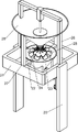
Fig. 1 is a schematic perspective view of the present invention.
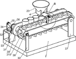
Fig. 2 is a schematic perspective view of a first part of the present invention.
Fig. 3 is a schematic perspective view of a second part of the present invention.
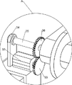
Fig. 4 is a perspective view of a third part of the present invention.
Fig. 5 is an enlarged schematic view of the structure of the present invention a.
FIG. 6 is an enlarged schematic view of the present invention B.
FIG. 7 is an enlarged schematic view of the present invention C.
Description of the reference numerals: 1: bottom plate, 2: unloading mechanism, 20: a bracket, 21: connection frame, 22: connecting block, 23: first hopper, 24: first connecting rod, 25: chute plate, 26: support bar, 27: support block, 28: second hopper, 3: transport mechanism, 30: first bearing seat, 31: support, 32: servo motor, 33: missing tooth gear, 34: second bearing housing, 35: rotating shaft, 36: full-tooth gear, 37: third bearing seat, 38: roller, 39: conveyor belt, 310: bump, 4: guide block, 5: baffle, 6: spring, 7: connecting plate, 8: roller, 9: second connecting rod, 10: electric putter, 11: push rod, 12: third connecting rod, 13: connection ring, 14: l-shaped pusher block, 15: a movable disk.
Detailed Description
In order to make the objects, technical solutions and advantages of the present invention more apparent, the present invention will be described in further detail with reference to the accompanying drawings in conjunction with the following detailed description. It should be understood that the description is intended to be exemplary only, and is not intended to limit the scope of the present invention. Moreover, in the following description, descriptions of well-known structures and techniques are omitted so as to not unnecessarily obscure the concepts of the present invention.
Example 1
The utility model provides an equipment of filling planting soil fast, as shown in fig. 1-6, including bottom plate 1, unloading mechanism 2, transport mechanism 3, guide block 4, baffle 5, spring 6, connecting plate 7 and gyro wheel 8, the middle part is equipped with unloading mechanism 2 on the bottom plate 1, be equipped with transport mechanism 3 on the bottom plate 1, the bilateral symmetry of 2 lower parts of unloading mechanism is equipped with guide block 4, the gliding style is equipped with baffle 5 on the guide block 4 of the left and right sides, be connected with spring 6 between baffle 5 front side and the unloading mechanism 2, baffle 5 front side bottom fixedly connected with connecting plate 7, the lower part of 7 rear sides of connecting plate is equipped with gyro wheel 8.
The blanking mechanism 2 comprises a bracket 20, a connecting frame 21, connecting blocks 22, a first hopper 23, first connecting rods 24, a chute plate 25, supporting rods 26, supporting blocks 27 and a second hopper 28, the bracket 20 is symmetrically and fixedly connected with the middle of the bottom plate 1 in a front-back manner, the rear side of the upper part of the bracket 20 at the front side is connected with a spring 6, the connecting frames 21 are connected between the brackets 20 at the front side and the rear side through bolts, the connecting blocks 22 are arranged at the front side and the rear side and the left side and the right side inside the connecting frame 21, the first hopper 23 is arranged between the connecting blocks 22, the guide blocks 4 are connected at the left side and the right side of the bottom of the first hopper 23, the first connecting rods 24 are arranged at the front side and the rear side and the left side inside the first hopper 23, the chute plate 25 is arranged between the first connecting rods 24, the supporting rods 26 are arranged at the front side and the rear side of the top of the connecting frame 21, the supporting blocks 27 are arranged at the left side and the top of the connecting frame 21, the supporting blocks 27 are arranged between the top ends of the second hopper 28, the upper portions of the support rods 26 each pass through a second funnel 28.
The conveying mechanism 3 comprises a first bearing seat 30, a support piece 31, a servo motor 32, a tooth-lacking gear 33, a second bearing seat 34, a rotating shaft 35, a full-tooth gear 36, a third bearing seat 37, a rolling shaft 38, a conveying belt 39 and a bump 310, wherein the first bearing seat 30 is installed on the left front side of the bottom plate 1, the support piece 31 is fixedly connected with the left rear side of the bottom plate 1, the servo motor 32 is installed on the top of the support piece 31, the tooth-lacking gear 33 is connected onto an output shaft of the servo motor 32, the second bearing seat 34 is installed on the rear side of the top of the support piece 31, the rotating shaft 35 is rotatably arranged in the second bearing seat 34, the front end of the rotating shaft 35 is rotatably connected with the first bearing seat 30, the full-tooth gear 36 is arranged on the rear portion of the rotating shaft 35, the full-tooth gear 36 is located above the tooth-lacking gear 33 and is matched with the tooth-lacking gear 33, the third bearing seats 37 are symmetrically installed on the front and back of the right side of the bottom plate 1, the rolling shaft 38 is rotatably arranged between the third bearing seats 37, the rotating shaft 35 is fixedly provided with a roller 38, the rollers 38 on the two sides are wound with a conveyor belt 39, the front side of the conveyor belt 39 is uniformly provided with lugs 310 at intervals, and the lugs 310 are in fit contact with the rollers 8.
When people need to fill planting soil into the flowerpot, the device can be used, firstly, enough planting soil is put in the blanking mechanism 2, then the flowerpots are sequentially arranged on the conveying mechanism 3, the conveying mechanism 3 drives the flowerpots to move rightwards, when one of the flowerpots moves to the lower part of the blanking mechanism 2, the conveying mechanism 3 just pushes the roller 8 and the connecting plate 7 forwards, thereby driving the baffle 5 to move forwards, the spring 6 is compressed by the baffle 5 and does not block the feeding mechanism 2 any more, the planting soil can fall into the flowerpot from the feeding mechanism 2, then the flowerpot will move to the right, the transmission mechanism 3 will not push the roller 8 and the connecting plate 7 any more, under the reset action of the spring 6, the roller 8, the connecting plate 7 and the baffle 5 are restored to the original position backwards, the baffle 5 blocks the blanking mechanism 2 again, the planting soil does not fall downwards, reciprocating like this, just can be constantly filling into the flowerpot through unloading mechanism 2 and transport mechanism 3 planting soil in proper order.
When people need carry out the unloading through unloading mechanism 2, put into second funnel 28 with the planting soil of capacity in, the opening that planting soil can pass through second funnel 28 bottom slowly drops to chute board 25 on, then planting soil can slowly drop once more through the chute on the chute board 25, under the initial condition, the opening of first funnel 23 bottom is blocked by baffle 5, and planting soil can not drop downwards, when baffle 5 removed, planting soil just can drop automatically.
When people need to intermittently move the flowerpot to the right through the conveying mechanism 3 and control the movement of the baffle 5, the output shaft of the servo motor 32 drives the gear 33 with the missing teeth to rotate anticlockwise, when the gear 33 with the missing teeth is meshed with the gear 36 with the full teeth, the gear 36 with the full teeth is driven to rotate clockwise, the rotating shaft 35 and the roller 38 on the left side are driven to rotate clockwise, the conveyor belt 39 and the roller 38 on the right side are driven to rotate clockwise, the flowerpot on the conveyor belt 39 is driven to move to the right, when the gear 33 with the missing teeth is disengaged from the gear 36 with the full teeth, the conveyor belt 39 and the flowerpot on the conveyor belt cannot move, the flowerpot is just positioned below the first hopper 23, the lug 310 just pushes the roller 8 and the connecting plate 7 forwards, the baffle 5 does not block the first hopper 23 any more, the planting soil in the first hopper 23 can fall into the flowerpot, and the flowerpot moves back and forth in the right direction, so that the flowerpot can be intermittently moved to the right, and the discharging is carried out when the flowerpot stops moving.
Example 2
On the basis of embodiment 1, as shown in fig. 4 and 7, the electric push rod device further includes a second connecting rod 9, an electric push rod 10, a push rod 11, a third connecting rod 12, a connecting ring 13 and L-shaped push blocks 14, the top of the supporting rod 26 is fixedly connected with the second connecting rod 9, the electric push rod 10 is installed between the second connecting rods 9, the push rod 11 is arranged at the bottom of the electric push rod 10, the third connecting rods 12 are fixedly connected to the periphery of the lower portion of the push rod 11, the outer ends of the third connecting rods 12 are provided with the connecting rings 13, and the L-shaped push blocks 14 are uniformly arranged outside the connecting rings 13 at intervals.
The device also comprises a movable disc 15, the lower part of the push rod 11 is provided with the movable disc 15, and the movable disc 15 is positioned above the third connecting rod 12.
The electric push rod 10 between the second connecting rods 9 is started, so that the push rod 11 and the third connecting rod 12 are driven to move up and down continuously, the connecting ring 13 and the L-shaped push block 14 are driven to move up and down continuously, the planting soil on the inclined groove plate 25 can be pushed out through the L-shaped push block 14, the planting soil is prevented from being accumulated on the inclined groove plate 25, and the electric push rod 10 is closed after the electric push rod is used.
The movable disk 15 is also moved up and down by the push rod 11 so that the planting soil in the second hopper 28 can be better dropped.
The above description is only for the specific embodiments of the present invention, but the scope of the present invention is not limited thereto, and any person skilled in the art can easily conceive of the changes or substitutions within the technical scope of the present invention, and all the changes or substitutions should be covered within the scope of the present invention. Therefore, the protection scope of the present invention shall be subject to the protection scope of the appended claims.