CN111661768B - Method and system for hoisting multiple peripheral components of assembly type building - Google Patents
Method and system for hoisting multiple peripheral components of assembly type building Download PDFInfo
- Publication number
- CN111661768B CN111661768B CN202010551001.0A CN202010551001A CN111661768B CN 111661768 B CN111661768 B CN 111661768B CN 202010551001 A CN202010551001 A CN 202010551001A CN 111661768 B CN111661768 B CN 111661768B
- Authority
- CN
- China
- Prior art keywords
- vertical
- frame
- track
- trolley
- transport
- Prior art date
- Legal status (The legal status is an assumption and is not a legal conclusion. Google has not performed a legal analysis and makes no representation as to the accuracy of the status listed.)
- Active
Links
Images


Classifications
-
- B—PERFORMING OPERATIONS; TRANSPORTING
- B66—HOISTING; LIFTING; HAULING
- B66C—CRANES; LOAD-ENGAGING ELEMENTS OR DEVICES FOR CRANES, CAPSTANS, WINCHES, OR TACKLES
- B66C23/00—Cranes comprising essentially a beam, boom, or triangular structure acting as a cantilever and mounted for translatory of swinging movements in vertical or horizontal planes or a combination of such movements, e.g. jib-cranes, derricks, tower cranes
- B66C23/18—Cranes comprising essentially a beam, boom, or triangular structure acting as a cantilever and mounted for translatory of swinging movements in vertical or horizontal planes or a combination of such movements, e.g. jib-cranes, derricks, tower cranes specially adapted for use in particular purposes
- B66C23/26—Cranes comprising essentially a beam, boom, or triangular structure acting as a cantilever and mounted for translatory of swinging movements in vertical or horizontal planes or a combination of such movements, e.g. jib-cranes, derricks, tower cranes specially adapted for use in particular purposes for use on building sites; constructed, e.g. with separable parts, to facilitate rapid assembly or dismantling, for operation at successively higher levels, for transport by road or rail
- B66C23/28—Cranes comprising essentially a beam, boom, or triangular structure acting as a cantilever and mounted for translatory of swinging movements in vertical or horizontal planes or a combination of such movements, e.g. jib-cranes, derricks, tower cranes specially adapted for use in particular purposes for use on building sites; constructed, e.g. with separable parts, to facilitate rapid assembly or dismantling, for operation at successively higher levels, for transport by road or rail constructed to operate at successively higher levels
- B66C23/283—Cranes comprising essentially a beam, boom, or triangular structure acting as a cantilever and mounted for translatory of swinging movements in vertical or horizontal planes or a combination of such movements, e.g. jib-cranes, derricks, tower cranes specially adapted for use in particular purposes for use on building sites; constructed, e.g. with separable parts, to facilitate rapid assembly or dismantling, for operation at successively higher levels, for transport by road or rail constructed to operate at successively higher levels with frameworks composed of assembled elements
-
- B—PERFORMING OPERATIONS; TRANSPORTING
- B66—HOISTING; LIFTING; HAULING
- B66C—CRANES; LOAD-ENGAGING ELEMENTS OR DEVICES FOR CRANES, CAPSTANS, WINCHES, OR TACKLES
- B66C11/00—Trolleys or crabs, e.g. operating above runways
-
- B—PERFORMING OPERATIONS; TRANSPORTING
- B66—HOISTING; LIFTING; HAULING
- B66C—CRANES; LOAD-ENGAGING ELEMENTS OR DEVICES FOR CRANES, CAPSTANS, WINCHES, OR TACKLES
- B66C23/00—Cranes comprising essentially a beam, boom, or triangular structure acting as a cantilever and mounted for translatory of swinging movements in vertical or horizontal planes or a combination of such movements, e.g. jib-cranes, derricks, tower cranes
- B66C23/62—Constructional features or details
-
- E—FIXED CONSTRUCTIONS
- E04—BUILDING
- E04G—SCAFFOLDING; FORMS; SHUTTERING; BUILDING IMPLEMENTS OR AIDS, OR THEIR USE; HANDLING BUILDING MATERIALS ON THE SITE; REPAIRING, BREAKING-UP OR OTHER WORK ON EXISTING BUILDINGS
- E04G21/00—Preparing, conveying, or working-up building materials or building elements in situ; Other devices or measures for constructional work
- E04G21/14—Conveying or assembling building elements
- E04G21/16—Tools or apparatus
- E04G21/162—Handles to carry construction blocks
Landscapes
- Engineering & Computer Science (AREA)
- Mechanical Engineering (AREA)
- Architecture (AREA)
- Structural Engineering (AREA)
- Transportation (AREA)
- Civil Engineering (AREA)
- Conveying And Assembling Of Building Elements In Situ (AREA)
Abstract
The invention discloses a method and a system for hoisting a plurality of peripheral components of an assembly type building, wherein the method comprises the following steps: vertical conveyer, travelling bogie, vertical steelframe, horizontal transportation track. The transport trolley is provided with a turnover frame and a moving part, the transport trolley can lift on a vertical steel frame along with a vertical transport device, a horizontal transport rail is supported by a triangular truss fixed on a wall, and the vertical steel frame and the horizontal rail triangular truss can lift along with the lifting of the building height. Vertical conveyer that carries travelling bogie traveles to the regulation height along with vertical rack, vertical conveyer traveles track and the floor around horizontal track through connection from the area at this moment, the last upset frame of travelling bogie overturns the prefab to predetermined angle, back through horizontal track travel to assigned position, the rethread travelling bogie hangs the prefab from the mobile device of area and moves to embedded reinforcement top, accurate alignment slowly falls into, dock rapidly through applying neotype connection method, thereby accomplish the hoist and mount.
Description
Technical Field
The invention relates to the field of building construction hoisting, in particular to a method and a system for hoisting a plurality of peripheral components of an assembly type building.
Background
The development of assembly type buildings is a necessary trend in the building industry, and the traditional building operation mode cannot meet the requirement of 'green China' in China. The country supports and develops energy-saving and environment-friendly green buildings, wherein the assembly type buildings become the development key point. The advantages of the fabricated building are more obvious compared with the traditional building, such as the aspects of building efficiency, building quality, building cost, resource consumption and the like.
In carrying out the assembled construction process, the hoist and mount of assembled component is heavily important, has formulated one set of safe and reliable efficient hoist and mount scheme and will directly influence going on smoothly of whole engineering, and the hoist and mount of assembled component mainly used is the tower crane at present, and along with the continuous promotion that each aspect required, the not enough of tower crane is more and more obvious. For example, the method has the advantages of economic aspects, high installation cost, short service life, low economy and the like; in consideration of the safety aspect, the tower crane lifting device needs to be used carefully in a height-limited area, needs to prevent collision when the towers are grouped, has high danger coefficient for operators, large risk in the dismantling stage and high operation requirement, and particularly generates great potential safety hazards on the ground within the operation radius when the tower crane is lifted. The defects of the tower crane directly influence the economy, safety and high efficiency of the existing scheme.
In view of the above, a plurality of peripheral component hoisting schemes for an assembly building need to be developed.
Disclosure of Invention
The invention aims to overcome the defects and shortcomings in the existing hoisting scheme of an assembly type building component, mainly solves the problems of hoisting and transporting a plurality of peripheral components of the assembly type building, and provides a method and a system for hoisting the plurality of peripheral components of the assembly type building.
The invention is realized by adopting the following technical scheme:
a hoisting system for a plurality of peripheral components of an assembly type building comprises a vertical steel frame located beside the assembly type building, wherein a vertical transportation device is installed on the vertical steel frame and comprises a vertical part and a transportation platform, a stabilizing frame surrounding the vertical steel frame is arranged on the vertical part, the vertical part is connected with the vertical steel frame through a transmission mechanism, and a section of movable track A is arranged on the surface, close to one side of the assembly type building, of the transportation platform; a fixed track B is horizontally arranged around the periphery of a to-be-built floor of the assembly type building through a support piece, and the movable track A and the fixed track B can be combined into a complete closed track ring; the movable track A on the transportation platform is provided with a transportation trolley, the transportation trolley comprises a trolley base, the trolley base is provided with wheels and is driven by a motor, the wheel tread is in contact with the rail surface, the wheel flange of the wheel tread is clamped at the rail waist of the track, the trolley base is installed at the bottom of the turnover frame in a hinged mode, one or more turnover oil cylinders are installed between the trolley base and the back of the turnover frame to achieve turnover frame movement, the turnover oil cylinders are driven by a hydraulic system on the trolley base, the top of the turnover frame is provided with one or more extension frames vertically arranged with the front of the turnover frame, each extension frame is provided with a moving portion moving along the extension frames, and the lifting mechanism capable of achieving lifting movement is arranged on the moving portion.
Preferably, the vertical steel frame is provided with a vertical rack, and the vertical part of the vertical transportation device is provided with a plurality of output gears meshed with the vertical rack.
The method for hoisting the plurality of peripheral components of the fabricated building applied to the system comprises the following steps:
(1) the vertical transportation device is located at the bottom layer, the transportation trolley is located on a movable track A of a transportation platform of the vertical transportation device, the overturning frame of the transportation trolley lies on the transportation platform, the peripheral prefabricated components of the plurality of blocks are hung to the transportation platform of the vertical transportation device by means of external hoisting equipment, and one prefabricated component is connected with the hoisting mechanism.
(2) The vertical steel frame lifts the vertical transportation device to a preset height through the transmission mechanism, and the power source of the vertical transportation device is a transmission system and is provided with a motor. At the moment, a movable track A on the vertical transportation device is communicated with a fixed track B around the floor to be built to form a closed track ring. The fixed track B is positioned around the floor to be built and laid on a support, and the support is a triangular truss fixed on a wall body at a certain distance through bolts.
(3) The prefabricated part is slowly turned to a preset installation angle by the turning frame through the action of a turning oil cylinder on the transport trolley; the overturning process is realized through a hydraulic system, the overturning angle can be adjusted through the telescopic degree of the overturning oil cylinder, and the importance of the adjustment is firstly embodied in whether the required balance can be realized when the transport trolley travels, so that the transport trolley is ensured to stably travel on a horizontal rail.
(4) The transport trolley can freely drive away from the vertical transport device through the penetrated track and drive to the outer side of the preset installation position through the fixed track B; the power source of the transport trolley is a motor on the trolley, and the motor drives wheels of the trolley to run on the track. If a plurality of transport trolleys exist, other transport trolleys can drive the vertical transport device at the moment, and the next transport is repeated.
(5) The prefabricated part is moved to the position above the embedded steel bars through a moving part of an extending frame on the transport trolley, and the prefabricated part is slowly dropped into the embedded steel bars through a hoisting mechanism after being accurately aligned; the moving part on the transport trolley is matched with the hoisting mechanism to realize the horizontal and vertical movement of the prefabricated part.
(6) And adjusting the verticality, and rapidly finishing butt joint by using a dry connection method so as to finish hoisting. The dry type connecting method is relative to the traditional wet operation method of sleeve grouting, and the dry type connecting method is characterized in that the steel bar joint of the prefabricated member, namely the bottom of the prefabricated member, is not totally closed in the traditional way, but an operable space is reserved in the inner side, and when the steel bars at the bottom of the prefabricated member are vertically aligned with the steel bars pre-embedded at the lower part, the upper steel bars and the lower steel bars with the positive and negative turnbuckles can be quickly and firmly connected through the sleeve with the positive and negative turnbuckles which is pre-assembled.
(7) And (4) driving the transport trolley back to the vertical transport device, carrying out next overturning and transporting task, and repeating the steps (3) to (6) until all prefabricated parts on the vertical transport device are hoisted.
Preferably, the two transport trolleys can be driven in opposite directions simultaneously according to actual conditions, and if necessary, the extension frames of the two transport trolleys are connected through the connecting track guide frame and then combined into a temporary truss vehicle so as to transport large-volume or large-mass components.
Preferably, the supporting member is a triangular truss fixed on the wall at a certain distance by bolts, when the fixed track B needs to climb, the triangular truss is directly fixed on the bolts embedded above, and the fixed track B is hung and fixed to the triangular truss by using the temporary electric hoist.
During construction, the turnover frame is arranged on the transport trolley, the transport trolley can lift on the vertical steel frame along with the vertical transport device, the rack is attached to the vertical steel frame, the fixed track B is supported by the triangular truss fixed on the wall, and the vertical steel frame and the horizontal track triangular truss can be lifted along with the lifting of the building height. The prefab is hung to vertical conveyer's transport platform on and with the upset frame connection of travelling bogie by outside hoisting accessory, the vertical conveyer who carries the travelling bogie utilizes vertical rack to travel to the regulation height, the orbit A that traveles of transport means from the area at this moment and the fixed orbit B through connection around the floor, the travelling bogie overturns the prefab to predetermined angle through the upset frame, back travelling bogie traveles to the assigned position through horizontal track by oneself, the removal portion of rethread travelling bogie from the area hangs the prefab and moves to embedded steel bar top, utilize lift hoisting mechanism slowly to fall into after accurate alignment, dock rapidly through the application dry-type connection method, thereby accomplish the hoist and mount. And then the transport trolley drives back to the vertical transport device again, continues to process the second prefabricated part, and repeats the turning and transporting tasks of the rest prefabricated parts until all the prefabricated parts on the vertical transport device are installed.
The invention has reasonable design, can well solve the problems of safety, economy and the like in the existing scheme, has low manufacturing cost and high automation degree, further improves the construction efficiency, has small operation radius compared with the existing scheme, has relatively small danger to people and objects on the ground, greatly reduces the potential safety hazard, is convenient to operate compared with the existing scheme, and is easy to control the building quality.
Drawings
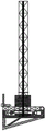
Fig. 1 shows a schematic view of a vertical transport device.
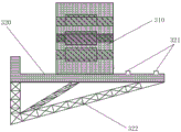
Fig. 2 shows a front view of the vertical transport device.
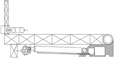
Fig. 3 shows a schematic view of the transport trolley structure.
Figure 4a shows a front view of the transport trolley (lying flat).
Figure 4b shows a (overturned) front view of the trolley.
Fig. 5 shows a schematic view of the transport trolley in cooperation with a vertical transport device.
Figure 6a shows a front view of the trolley (lying flat) in cooperation with a vertical transport.
Figure 6b shows a front view of the trolley (flipped) in combination with a vertical transport.
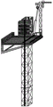
Fig. 7a shows the combination of the transport trolley (lying down), the vertical transport device and the vertical steel frame.
Fig. 7b shows the front view of the combination of the transport trolley (lying flat), the vertical transport device and the vertical steel frame.
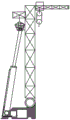
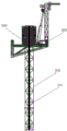
Fig. 8a shows a schematic diagram of the combination of a transport trolley (turnover), a vertical transport device and a vertical steel frame.
Fig. 8b shows a front view of the combination of the transport trolley (tip-over), vertical transport device, vertical steel frame.
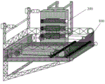
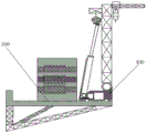
Fig. 9 is an overall schematic view of the assembled building multi-block peripheral component hoisting system.
Fig. 10 shows a schematic view of two transport carriages constituting a temporary truss.
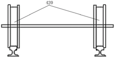
Fig. 11 shows a schematic view of the wheels and rails of the transport cart.
In the figure: 100-fabricated building, 101-to-be-built floor, 102-supporting piece, 103-fixed track B; 200-vertical steel frame, 201-vertical rack; 300-vertical transportation device, 310-vertical part, 320-transportation platform, 311-stabilizing frame, 312-output gear, 313-lifting motor, 321-movable track A, 322-triangular support frame; 400-transport trolley, 410-trolley base, 411-trolley bottom counterweight, 420-wheel, 430-turnover frame, 431-frame balance counterweight, 440-turnover oil cylinder, 450-hydraulic system, 460-extension frame, 461-cross bar, 470-moving part, 480-hoisting mechanism, 481-fixed pulley, 482-movable pulley and 490-connecting track guide frame.
Detailed Description
The following detailed description of specific embodiments of the invention refers to the accompanying drawings.
A hoisting system for a plurality of peripheral components of an assembly type building comprises a vertical steel frame 200, a vertical transportation device 300 and a transportation trolley 400.
As shown in fig. 9, the vertical steel frame 200 is constructed beside the prefabricated building 100, and the vertical transportation device 300 is installed on the vertical steel frame 200. As shown in fig. 1 and 2, the vertical transportation device 300 includes a vertical portion 310 and a transportation platform 320, a stabilizing frame 311 surrounding a vertical steel frame is arranged on the vertical portion 310 of the vertical transportation device 300, the vertical portion 310 is connected with the vertical steel frame 200 through a transmission mechanism, specifically, a vertical rack 201 is arranged on the vertical steel frame 200, a plurality of lifting motors 313 are arranged in the vertical portion 310 of the vertical transportation device 300 and respectively drive an output gear 312 to be meshed with the vertical rack 201, and the vertical portion 310 can be further connected with the vertical steel frame through a connecting frame in a sliding manner to realize longitudinal positioning; the transportation platform 320 is provided with a section of movable track a321 near one side surface of the prefabricated building 100. As shown in fig. 9, a fixed track B103 is horizontally installed around a floor 101 to be built of the prefabricated building 100 by means of a support member 102, and a movable track a321 and the fixed track B103 can be combined into a complete closed track loop.
As shown in fig. 5, a transport cart 400 is provided on the movable rail a321 of the transport platform 320. As shown in fig. 3, the transportation cart 400 includes a cart base 410, the cart base 410 is provided with wheels 420 and is driven by a motor, treads of the wheels 420 contact with rail surfaces, and flanges thereof are clamped at rail waists of the rails (as shown in fig. 11), the cart base 410 is provided with a cart bottom counterweight 411; the bottom of the vehicle base 410 is hinged with the bottom of the turnover frame 430 through a rotating shaft, one or more turnover oil cylinders 440 are arranged between the vehicle base 410 and the back of the turnover frame 430 to realize the movement of the turnover frame 430 (as shown in fig. 4b, two turnover oil cylinders are provided), the turnover oil cylinders 440 are driven by a hydraulic system 450 arranged on the vehicle base 410, the hydraulic system mainly comprises a motor, a coupling, a hydraulic pump and a distribution valve, the coupling is driven by the motor to drive the hydraulic pump, the hydraulic pump drives the oil cylinders to stretch and retract through the distribution valve to realize turnover, and the turnover angle can be adjusted through the stretching degree of the oil cylinders; as shown in fig. 3, the top of the turnover frame 430 is provided with one or two extending frames 460 arranged perpendicular to the front surface of the turnover frame 430, each extending frame 460 is provided with a moving part 470 moving along the extending frame, the moving part 470 is provided with a lifting mechanism 480 capable of realizing lifting movement, and a cross bar 461 is connected between adjacent extending frames 460.
A hoisting construction method for a plurality of peripheral components of an assembly type building comprises the following steps:
firstly, a vertical steel frame 200 is built beside an assembly building to be built, and then a vertical transportation device 300 and a transportation trolley 400 are installed. As shown in fig. 7b, the vertical transport device 300 is located at the bottom of the steel frame, the transportation cart 400 is located on the movable track a321 of the transportation platform 320 of the vertical transport device 300, the turnover frame 430 of the transportation cart 400 is laid on the transportation platform 320 (as shown in fig. 6 a), a plurality of peripheral prefabricated components are hoisted to the transportation platform 320 by means of external hoisting equipment, and one of the prefabricated components is connected with the hoisting mechanism 480. Wherein a triangular support 321 is fixed under the transportation platform 320 in order to enhance the carrying capacity thereof.
Specifically, the hoisting mechanism 480 on the transportation trolley 400 at least comprises a set of movable pulleys 482 and fixed pulleys 481, and belongs to the existing mature structure. The upper end of the prefabricated member is connected with a movable pulley 22 on a hoisting mechanism 480 through a steel wire rope, and a motor is arranged in the hoisting mechanism 480 to realize the lifting of the movable pulley 480.
Step two, the vertical transportation device 300 is attached to the rack 201 of the vertical steel frame 200 through the output gear 312, the vertical transportation device 300 moves up and down along the vertical steel frame 200 through the lifting motor 313 to lift the transportation trolley 400 to a predetermined height (as shown in fig. 7 a), and at this time, the transportation track a321 of the vertical transportation device 300 is connected with the fixed track B103 around the floor to be built in a penetrating manner (as shown in fig. 9).
The power source of the vertical transportation device 300 is a transmission system, the transmission system mainly comprises motors, couplers, speed reducers and output gears, the transmission system is driven by multiple motors, the power of the three motors drives the output gears on the back to rotate after passing through the couplers and the speed reducers, and the output gears in operation are meshed with racks on the vertical steel frame to realize lifting. In addition, the vertical transport device is also provided with a safety control system and an electrical system, wherein the safety control system is equipped with a cone drum speed limiter as an anti-falling safety device.
Also, to prevent the vertical transportation device from overturning or derailing, a stabilizer 311 that can embrace the vertical steel frame 200 is designed particularly at the rear of the vertical portion 310, as shown in fig. 1.
And step three, turning the prefabricated member to a preset installation angle by using a turning frame on the transport trolley, as shown in figures 8a and 8 b.
In particular, the overturning frame on the transport trolley is not in a conventional flat plate shape, but is in a hollow frame shape, and the structure is favorable for realizing repeated overturning and hoisting of a plurality of members. When the transport trolley drives back to the vertical transport device after completing the first hoisting, the hollow frame of the transport trolley is turned to a state (approximate to a lying state) capable of being connected with the second prefabricated member, the second prefabricated member is connected with the movable pulley of the hoisting mechanism at the moment, then the second prefabricated member is turned to a driving state, namely, the second prefabricated member is approximate to a vertical state, and then the transport trolley drives on the track.
The turnover process of the turnover frame 430 on the transport trolley 400 is realized through a hydraulic system, the hydraulic system mainly comprises a motor, a coupling, a hydraulic pump, a distribution valve, the coupling is driven by the motor, the hydraulic pump is driven by the coupling, the hydraulic pump drives the turnover oil cylinder 440 to stretch through the distribution valve, and then turnover is realized, the turnover angle can be adjusted through the stretching degree of the turnover oil cylinder, the importance of the adjustment is firstly embodied in whether the required balance can be realized when the transport trolley travels, and therefore the transport trolley is ensured to stably travel on a horizontal track. Therefore, the transportation trolley mainly solves the strength bearing problem and the overturn prevention problem, wherein the strength bearing problem can be solved by improving the steel strength of the trolley, the trolley is made of steel with higher strength, and the overturn prevention problem is more critical, so that a controller (provided with a balance sensor) on the transportation trolley can freely adjust the inclination degree of a component through a hydraulic system, the gravity center of the carried component is freely adjusted, and the component can safely and stably move along with the transportation trolley. And the cross section of the track is I-shaped, and the wheels 420 of the transport trolley comprise treads and wheel rims, wherein the treads are in contact with the track surface, and the wheel rims on the two sides are clamped on the two sides of the track.
Step four, as shown in fig. 6B, after the transportation trolley 400 on the vertical transportation device 300 turns the components to a proper angle by using the turning frame 430, the transportation trolley 400 is driven away from the vertical transportation device 300 and driven to the outside of the predetermined installation position through the fixed track B103, as shown in fig. 9.
Specifically, the power source for the transportation cart 400 is an electric motor on the cart that drives the wheels of the cart to travel on the rails. The transport trolley can freely drive away from the vertical transport device through the through track, stably drive to the outer side of the preset installation position along the fixed track B, and if a plurality of transport trolleys exist, other transport trolleys can drive on the vertical transport device at the moment to repeat the next transport. The fixed track B is positioned around a floor to be built and laid on a support, and the support is a triangular truss fixed on a wall body at a certain distance through bolts. When the fixed track B needs to climb, the triangular truss is directly fixed on the bolts embedded above, and the track is hung to the triangular truss and fixed by the temporary electric hoist. For the stability and bearing capacity of the transportation track, firstly, high-strength steel bars are adopted, and secondly, the supporting points of the track can be properly increased.
The two transport trolleys can be lifted successively according to actual conditions, are lifted in a staggered mode and run in opposite directions, and can be combined into a temporary combined truss vehicle when necessary, as shown in figure 10, so that large-volume or large-mass components can be transported conveniently.
The width of the bottom of the transport trolley is large, the actual stress of the transport trolley when the transport trolley is fully loaded is fully considered in the design, and the bottom of the transport trolley is additionally provided with a vehicle bottom counterweight 411 to prevent the transport trolley from overturning in the carrying process. And step three, simultaneously, the inclination degree of the turnover plate can be controlled by controlling the telescopic degree of the turnover oil cylinder during turnover, so that the balance of the whole transport trolley is further adjusted, and the transport trolley is ensured to run safely and stably. Further, a frame balancing weight 431 is provided on the rear surface of the inversion frame 430 to balance the entire transportation process.
And step five, moving the prefabricated part to the position above the embedded steel bars through a moving device arranged above the transport trolley, and after the prefabricated part is accurately aligned, controlling a hoisting mechanism 480 to realize that the prefabricated part slowly falls into the embedded steel bars.
Specifically, the moving part 470 of the transportation cart 400 can freely move along the extension 460 through the motor, and the lifting mechanism 480 is matched to realize the horizontal and vertical movement of the components. In the movement process of the moving part hoisting prefabricated part, the overturning oil cylinder controls the overturning frame to fall back in the opposite direction, so that the balance of the transport trolley is always kept, the stress of the rail can be reduced, the structure quality is reduced, and the bearing capacity of the structure is improved.
And step six, adjusting the verticality and other parameters, and rapidly finishing butt joint by using a dry connection method so as to finish hoisting.
The dry type connecting method is relative to the traditional wet operation method of sleeve grouting, and the dry type connecting method is characterized in that the steel bar joint of the prefabricated member, namely the bottom of the prefabricated member, is not totally closed in the traditional way, but an operable space is reserved in the inner side, and when the steel bar at the bottom of the prefabricated member is aligned with the steel bar pre-embedded at the lower part, the upper and lower steel bars with the positive and negative turnbuckles can be quickly and firmly connected through the sleeve with the positive and negative turnbuckles which is pre-assembled.
And step seven, the transport trolley drives back to the vertical transport device again to perform the next overturning and transporting task, and the steps three to six are repeated until all prefabricated parts on the vertical transport device are hoisted.
The invention is mainly used for hoisting and transporting a plurality of peripheral components of an assembly type building, the peripheral components generally comprise an outer wall, a bay window, a balcony, a window and the like, the bay window or the outer wall has larger mass, the strength requirements of a vertical transportation system and a horizontal transportation system in the transportation of a plurality of components are higher, the installation is more complex, the installation requirement is higher, the invention is suitable for the hoisting operation with less assembly components, the transportation speed is reduced due to the transportation of a plurality of components, but a plurality of components can be lifted at one time, the transportation efficiency can be greatly improved, and the device is suitable for transporting a plurality of components which are more regular or have similar shapes.
All the related structural members meet the actual stress requirements, the design is reasonable, the problems in the aspects of safety, economy and the like in the existing scheme can be well solved, the scheme is low in manufacturing cost and high in automation degree, the construction efficiency is further improved, the scheme is small in operation radius compared with the existing scheme, the danger of people and objects on the ground is relatively small, the potential safety hazard is greatly reduced, and the building quality is easy to control compared with the existing scheme, so that the construction method is convenient to operate.
The invention has high automation degree, saves more labor cost, can directly lift a plurality of prefabricated parts at one time, and has the advantages of higher speed and higher efficiency compared with single-block lifting of a tower crane. Because this scheme can implement the operation closely, so compare traditional tower crane hoist and mount safer, swift, high-efficient, this scheme has stronger practicality and extensive application moreover.
While specific embodiments of the invention have been described above, it will be appreciated by those skilled in the art that the above examples are not intended to limit the invention in any way and that any arrangement which is calculated to achieve the above objectives, such as variations, modifications, equivalents, or equivalent arrangements, will fall within the scope of the invention.
Claims (10)
1. A method for hoisting a plurality of peripheral components of an assembly type building is characterized by comprising the following steps: the method comprises the following steps:
(1) the vertical steel frame (200) is built beside the assembly type building (100), a vertical transportation device (300) is installed on the vertical steel frame (200), the vertical transportation device (300) comprises a vertical part (310) and a transportation platform (320), a stabilizing frame (311) surrounding the vertical steel frame (200) is arranged on the back of the vertical part (310), the vertical part (310) is connected with the vertical steel frame (200) through a transmission mechanism, and a section of movable track A (321) is arranged on the surface, close to one side of the assembly type building (100), of the transportation platform (320); a fixed track B (103) is horizontally arranged around a floor (101) to be built of the assembly type building (100) through a support piece (102), and the movable track A (321) and the fixed track B (103) can be combined into a complete closed track ring; the transport trolley (400) is arranged on a movable track A (321) of the transport platform (320), the transport trolley (400) comprises a trolley base (410), the trolley base (410) is provided with wheels (420) and is driven by a motor, the treads of the wheels (420) are in contact with the rail surface, the rims of the wheels are clamped at the rail waist of the track, the trolley base (410) is hinged with the bottom of the turnover frame (430), one or more turnover cylinders (440) are arranged between the trolley base (410) and the back surface of the turnover frame (430) to realize the motion of the turnover frame (430), the turnover cylinders (440) are driven by a hydraulic system (450) arranged on the trolley base (410), one or more extension frames (460) which are vertically arranged with the front surface of the turnover frame (430) are arranged at the top of the turnover frame (430), and a moving part (470) moving along each extension frame (460) is arranged on each extension frame (460), a lifting mechanism (480) capable of realizing lifting motion is arranged on the moving part (470);
(2) the vertical transportation device (300) is positioned at the bottom layer, the transportation trolley (400) is positioned on a movable track A (321) of a transportation platform (320) of the vertical transportation device (300), an overturning frame (430) of the transportation trolley (400) is flatly laid on the transportation platform (320), a plurality of peripheral prefabricated components are hoisted to the transportation platform (320) by means of external hoisting equipment, and one prefabricated component is connected with a hoisting mechanism (480);
(3) the vertical steel frame lifts the vertical transportation device to a preset height through a transmission mechanism, and at the moment, a movable track A (321) arranged on the vertical transportation device (300) is communicated with a fixed track B (103) around the floor (101) to be built to form a closed track ring;
(4) turning the prefabricated part to a preset installation angle by using a turning oil cylinder (440) on the transport trolley (400) to act, and turning the prefabricated part to a preset installation angle by using a turning frame (430);
(5) the transport trolley drives away from the vertical transport device and runs to the outer side of the preset installation position through a fixed track B (103);
(6) the prefabricated part is moved to the position above the embedded steel bars through a moving part (470) arranged above the transport trolley (400), and the prefabricated part is slowly fallen into the embedded steel bars through a hoisting mechanism (480) after being accurately aligned;
(7) the verticality is adjusted, and the butt joint is rapidly completed by a dry connecting method, so that the hoisting is completed;
(8) and (4) the transport trolley drives back to the vertical transport device to perform next overturning and transporting task, and the steps (4) to (7) are repeated until all prefabricated parts on the vertical transport device are hoisted.
2. The method for hoisting the plurality of peripheral members of the prefabricated building according to the claim 1, wherein the method comprises the following steps: a plurality of transport trolleys (400) run on the fixed track B (103).
3. The method for hoisting the plurality of peripheral members of the prefabricated building as claimed in claim 1 or 2, wherein the method comprises the following steps: the extending frames (460) of the two transport trolleys (400) are connected through a connecting track guide frame (490) and then combined into a temporary truss trolley.
4. The method for hoisting the plurality of peripheral members of the prefabricated building according to the claim 1, wherein the method comprises the following steps: the supporting piece (102) is a triangular truss fixed on the wall body at a certain distance through bolts, when the fixed track B (103) needs to climb, the triangular truss is directly fixed on the bolts embedded above, and the fixed track B (103) is hung to the triangular truss and fixed through a temporary electric hoist.
5. The utility model provides an assembled building polylith peripheral component hoist and mount system which characterized in that: the assembly type building structure comprises a vertical steel frame (200) located beside an assembly type building (100), wherein a vertical transportation device (300) is installed on the vertical steel frame (200), the vertical transportation device (300) comprises a vertical part (310) and a transportation platform (320), a stabilizing frame (311) surrounding the vertical steel frame (200) is arranged on the back surface of the vertical part (310), the vertical part (310) is connected with the vertical steel frame (200) through a transmission mechanism, and a section of movable track A (321) is arranged on the transportation platform (320) and close to the surface of one side of the assembly type building (100); a fixed track B (103) is horizontally arranged around a floor (101) to be built of the assembly type building (100) through a support piece (102), and the movable track A (321) and the fixed track B (103) can be combined into a complete closed track ring; the transport trolley (400) is arranged on a movable track A (321) of the transport platform (320), the transport trolley (400) comprises a trolley base (410), the trolley base (410) is provided with wheels (420) and is driven by a motor, the treads of the wheels (420) are in contact with the rail surface, the rims of the wheels are clamped at the rail waist of the track, the trolley base (410) is hinged with the bottom of the turnover frame (430), one or more turnover cylinders (440) are arranged between the trolley base (410) and the back surface of the turnover frame (430) to realize the motion of the turnover frame (430), the turnover cylinders (440) are driven by a hydraulic system (450) arranged on the trolley base (410), one or more extension frames (460) which are vertically arranged with the front surface of the turnover frame (430) are arranged at the top of the turnover frame (430), and a moving part (470) moving along each extension frame (460) is arranged on each extension frame (460), the moving part (470) is provided with a lifting mechanism (480) capable of realizing lifting motion.
6. The system for lifting a plurality of exterior members of an assembly type building as claimed in claim 5, wherein: and a frame balance weight (431) is arranged on the back surface of the turnover frame (430).
7. The system for lifting a plurality of exterior members of an assembly type building as claimed in claim 5, wherein: a triangular support (322) is arranged on the bottom surface of the transportation platform (320).
8. The system for lifting a plurality of exterior members of an assembly type building as claimed in claim 5, wherein: the vertical steel frame (200) is provided with a vertical rack (201), and a vertical part (310) of the vertical transportation device (300) is provided with a plurality of output gears which are meshed with the vertical rack (201).
9. The system for lifting a plurality of exterior members of an assembly type building as claimed in claim 5, wherein: the vehicle base (410) is provided with a vehicle bottom counterweight (411).
10. The system for lifting a plurality of exterior members of an assembly type building as claimed in claim 9, wherein: a cross rod (461) is connected between the adjacent extending frames (460) on the transport trolley (400).
Applications Claiming Priority (2)
| Application Number | Priority Date | Filing Date | Title |
|---|---|---|---|
| CN202010422392 | 2020-05-19 | ||
| CN2020104223926 | 2020-05-19 |
Publications (2)
| Publication Number | Publication Date |
|---|---|
| CN111661768A CN111661768A (en) | 2020-09-15 |
| CN111661768B true CN111661768B (en) | 2021-07-16 |
Family
ID=72387515
Family Applications (1)
| Application Number | Title | Priority Date | Filing Date |
|---|---|---|---|
| CN202010551001.0A Active CN111661768B (en) | 2020-05-19 | 2020-06-17 | Method and system for hoisting multiple peripheral components of assembly type building |
Country Status (1)
| Country | Link |
|---|---|
| CN (1) | CN111661768B (en) |
Families Citing this family (1)
| Publication number | Priority date | Publication date | Assignee | Title |
|---|---|---|---|---|
| CN113086891B (en) * | 2021-03-30 | 2022-03-08 | 东莞市广运建筑工程有限公司 | Conveyer for assembly type building structure |
Citations (5)
| Publication number | Priority date | Publication date | Assignee | Title |
|---|---|---|---|---|
| US5881504A (en) * | 1995-05-15 | 1999-03-16 | Obayashi Corporation | Temporary frame system for construction |
| CN104563528A (en) * | 2014-12-22 | 2015-04-29 | 上海建工集团股份有限公司 | Rapid in-place device and rapid in-place method for prefabricated wallboard of prefabricated building |
| CN105293315A (en) * | 2015-11-12 | 2016-02-03 | 山东恒堃机械有限公司 | Hoisting equipment for assembly-type building prefabricated part |
| CN107686056A (en) * | 2017-10-17 | 2018-02-13 | 中国建筑第七工程局有限公司 | Special lifting platform and application method are installed in the lifting of assembly concrete building element |
| CN208054764U (en) * | 2018-04-03 | 2018-11-06 | 上海宝冶集团有限公司 | Construction material is vertical and horizontal transporter |
-
2020
- 2020-06-17 CN CN202010551001.0A patent/CN111661768B/en active Active
Patent Citations (5)
| Publication number | Priority date | Publication date | Assignee | Title |
|---|---|---|---|---|
| US5881504A (en) * | 1995-05-15 | 1999-03-16 | Obayashi Corporation | Temporary frame system for construction |
| CN104563528A (en) * | 2014-12-22 | 2015-04-29 | 上海建工集团股份有限公司 | Rapid in-place device and rapid in-place method for prefabricated wallboard of prefabricated building |
| CN105293315A (en) * | 2015-11-12 | 2016-02-03 | 山东恒堃机械有限公司 | Hoisting equipment for assembly-type building prefabricated part |
| CN107686056A (en) * | 2017-10-17 | 2018-02-13 | 中国建筑第七工程局有限公司 | Special lifting platform and application method are installed in the lifting of assembly concrete building element |
| CN208054764U (en) * | 2018-04-03 | 2018-11-06 | 上海宝冶集团有限公司 | Construction material is vertical and horizontal transporter |
Also Published As
| Publication number | Publication date |
|---|---|
| CN111661768A (en) | 2020-09-15 |
Similar Documents
| Publication | Publication Date | Title |
|---|---|---|
| CN111502293B (en) | Method and system for hoisting single peripheral component of assembly type building | |
| CN212450180U (en) | But lateral shifting's lift | |
| CN109653105B (en) | Main truss system of box girder bridge cantilever construction hanging basket and use method thereof | |
| CN114776029A (en) | Construction operation method and system for outer curtain wall of corridor of high-altitude large-span building | |
| CN214359875U (en) | Promote electronic monospar gantry crane who prevents rocking | |
| CN111661768B (en) | Method and system for hoisting multiple peripheral components of assembly type building | |
| CN210768841U (en) | Tunnel prefabricated assembled under-rail structure assembling trolley and control system thereof | |
| CN216038231U (en) | General gantry crane | |
| CN205526359U (en) | Prefab conveyer | |
| CN205739198U (en) | A kind of preform production transportation system | |
| CN205418901U (en) | Prefab conveyer | |
| CN113638312A (en) | Multi-functional bridge railing construction trolley | |
| CN209835463U (en) | Prefabricated bridge deck hoisting equipment | |
| CN211368408U (en) | Bridge erecting equipment for road and bridge construction | |
| CN215798047U (en) | Special crane for grinding roller | |
| CN205526360U (en) | Prefab conveyer | |
| CN205574940U (en) | Prefab conveyer | |
| CN205574936U (en) | Prefab conveyer | |
| CN117071440A (en) | Self-driven hydraulic lifting type steel bar pre-binding inner frame | |
| CN215925636U (en) | Multi-functional bridge railing construction trolley | |
| CN215052164U (en) | Bridge guardrail template dismouting platform | |
| CN205574939U (en) | Prefab conveyer | |
| CN205526358U (en) | Prefab production conveyor system | |
| CN205574938U (en) | Prefab production conveyor system | |
| CN111576245A (en) | Construction hanging basket for rail type bridge |
Legal Events
| Date | Code | Title | Description |
|---|---|---|---|
| PB01 | Publication | ||
| PB01 | Publication | ||
| SE01 | Entry into force of request for substantive examination | ||
| SE01 | Entry into force of request for substantive examination | ||
| GR01 | Patent grant | ||
| GR01 | Patent grant |