CN215798047U - Special crane for grinding roller - Google Patents
Special crane for grinding roller Download PDFInfo
- Publication number
- CN215798047U CN215798047U CN202122476956.7U CN202122476956U CN215798047U CN 215798047 U CN215798047 U CN 215798047U CN 202122476956 U CN202122476956 U CN 202122476956U CN 215798047 U CN215798047 U CN 215798047U
- Authority
- CN
- China
- Prior art keywords
- trolley
- lifting
- roof beam
- cart
- anchor clamps
- Prior art date
- Legal status (The legal status is an assumption and is not a legal conclusion. Google has not performed a legal analysis and makes no representation as to the accuracy of the status listed.)
- Active
Links
Images


Landscapes
- Carriers, Traveling Bodies, And Overhead Traveling Cranes (AREA)
Abstract
The utility model provides a special hoist of grinding roller, including the girder, the both ends of girder are equipped with the upper end roof beam, be equipped with the leg before lower end roof beam and the upper end roof beam, the both ends of end roof beam all are equipped with cart running gear, the top of two girders is equipped with first trolley and second trolley, all be equipped with the hoist under first trolley and the second trolley, the hoist includes a hoist supporting beam, hoist supporting beam's below is equipped with anchor clamps, anchor clamps include anchor clamps support, the top and the hoist supporting beam of anchor clamps support are connected, the spout has been seted up to the inboard of the lower extreme of anchor clamps support, it is the turbine to assemble in the spout, worm and turbine assembly, the upper and lower both ends of worm all pass through the rotatable assembly of bearing on anchor clamps support, and the upper end of worm extends anchor clamps support, the top of anchor clamps support is equipped with the motor of vertical setting, the power output shaft and the worm of motor pass to be connected. The utility model has simple structure and convenient use.
Description
Technical Field
The utility model belongs to the technical field of hoisting equipment, and particularly relates to a special crane for a grinding roller.
Background
The roll shaft is called as a grinding roller or a roller, and for some larger roll shafts, the roll shaft needs to be lifted to a roller machine for machining through hoisting equipment during frame machining, but the existing hoisting equipment is usually a forklift, the roll shaft is conveyed to the roller machine for machining through the forklift, the roll shaft is inconvenient to convey and easy to roll off from the forklift because the roll shaft is cylindrical, and the roll shaft is fastened through an iron chain in some production workshops, and then the roll shaft is lifted through a lifting hook. Therefore, the existing hoisting equipment for producing and processing the roll shaft cannot be well suitable for the requirements of workshops, the roll shaft is inconvenient to hoist and transport, the production efficiency is low, and safety accidents are easy to occur.
SUMMERY OF THE UTILITY MODEL
The utility model provides a special crane for a grinding roller, which aims to solve the technical problem that the existing roller shaft is inconvenient to hoist in machining, and comprises two main beams which are arranged in parallel at intervals, wherein the main beams play a supporting role, the two ends of each main beam are respectively provided with an upper end beam, the end parts of the two main beams are respectively detachably fixed with the upper end beams which are correspondingly arranged, the end part of the upper end beam at the left end of each main beam is provided with a cart travelling mechanism, the cart travelling mechanisms are assembled on cart travelling rails on a steel structure factory building, each cart travelling mechanism comprises cart travelling wheels and cart travelling motors, the cart travelling wheels are respectively assembled on the upper end beams, the upper end beams are provided with cart travelling motors, power output shafts of the cart travelling motors are in transmission connection with the cart travelling wheels, the cart travelling motors are started, and the cart travelling wheels are driven to rotate by the cart travelling motors. The lower extreme roof beam parallel with the upper end roof beam is equipped with under the upper end roof beam of the girder other end, the landing leg that is equipped with two vertical settings before lower end roof beam and the upper end roof beam, the landing leg plays the fixed effect of support, the upper end of landing leg corresponds respectively and fixes on the upper end roof beam, the lower extreme of landing leg corresponds respectively and fixes on the lower end roof beam, and the both ends of lower end roof beam all are equipped with cart running gear, cart running gear includes cart walking wheel and cart walking motor, cart walking wheel assembles respectively at the lower end roof beam, be equipped with cart walking motor on the lower end roof beam, cart walking motor's power output shaft and cart walking wheel transmission are connected. The dolly walking track has all been laid on the top of two girders, the top of two girders is equipped with first trolley and second trolley, first trolley and second trolley all assemble on the dolly walking track, first trolley and second trolley structure are the same, and first trolley and second trolley all include the dolly frame, the bottom four corners department of dolly frame all is equipped with the dolly walking wheel, be equipped with the transmission shaft between the dolly walking wheel of two coaxial lines, the centre of transmission shaft is equipped with dolly walking motor, dolly walking motor drives the transmission shaft and rotates, the transmission shaft drives dolly walking wheel and follows dolly walking rail mounted. The top of the trolley frame is provided with a lifting mechanism, the lifting mechanism comprises a lifting winding drum and a lifting motor, the lifting motor is assembled with the lifting winding drum, a steel wire rope is wound on the lifting winding drum, and the lifting motor drives the lifting winding drum to wind and unwind the steel wire rope on the winding drum, so that the lifting of the lifting appliance is realized. All be equipped with the hoist under first trolley and the second trolley, the hoist includes the hoist supporting beam with girder parallel arrangement, the hoist supporting beam plays the supporting role, the top of hoist supporting beam is equipped with two movable pulleys that set up to the car, two movable pulleys are rotatable assembly respectively at the both ends of hoist supporting beam, first trolley passes through wire rope and is connected with the movable pulley under rather than, the second trolley passes through wire rope and is connected with the movable pulley under rather than, it realizes the lift to hoist supporting beam through receiving and releasing wire rope to play to rise the reel. The below of hoist supporting beam is equipped with the anchor clamps that a plurality of interval set up, anchor clamps are including the anchor clamps support that is the type of falling U, fixed connection can be dismantled with hoist supporting beam on the top of anchor clamps support, the spout has been seted up to the inboard of the lower extreme of anchor clamps support, the cross-section of spout is the major arc form, be equipped with the turbine that is the major arc form in the spout, one side of anchor clamps support is equipped with the worm of vertical setting, worm and turbine assembly, the upper and lower both ends of worm all pass through the rotatable assembly of bearing on anchor clamps support, and the upper end of worm extends anchor clamps support, the top of anchor clamps support is equipped with the motor of vertical setting, the power output shaft and the worm transmission of motor are connected, the motor drives the worm and rotates, the worm drives the turbine and removes along the spout.
Preferably, all be equipped with guider under first trolley and the second trolley, guider includes the leading truck of vertical setting, the bottom of fixing at the dolly frame can be dismantled respectively to the top of leading truck, be equipped with the guide rail of vertical setting on the leading truck, the lower extreme of leading truck is equipped with the support frame, but support frame sliding assembly is on the leading truck, and the lower extreme of support frame extends to the leading truck below, the bottom of support frame can be dismantled fixedly with a hoist supporting beam, guider's setting has reduced the swing of hoist when hanging and getting the heavy object, stability has been strengthened.
Preferably, the bottom of one of them girder is equipped with electric block, and electric block's setting can be used for lifting by crane less heavy object, and the energy can be saved is light nimble.
Preferably, both ends of the upper end beam are provided with buffers which play a role in buffering; both ends of the lower end beam are provided with buffers.
Preferably, one side of landing leg is equipped with the climbing ladder that is used for the climbing jack-up, and the climbing ladder is convenient for maintenance personal to maintain the hoist.
The scheme has the following advantages:
the fixture is arranged in a mode of a worm wheel and a worm, the worm wheel is driven by the worm to move along the sliding chute, and the inner ring of the worm wheel is arc-shaped and is adaptive to the outer surface of a roller shaft to be hoisted, so that the outer surface of the roller shaft is uniformly stressed, and the extrusion force of the fixture to the roller shaft is reduced; the guide device plays a role in guiding, so that the swinging of the lifting appliance during the lifting of the roll shaft is reduced, and the stability is improved; the first hoisting trolley and the second hoisting trolley can work simultaneously, so that the working efficiency is improved; the electric hoist can be used for hoisting small heavy objects, saves energy, and is light and flexible.
Drawings
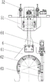
FIG. 1 is a schematic front view of the present invention;
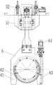
FIG. 2 is a left side view of the present invention;
FIG. 3 is a first schematic structural view of the fixture;
FIG. 4 is a second schematic structural view of the clamp;
fig. 5 is a schematic structural diagram of the spreader.
Reference numerals: 1. a main beam; 2. a lower end beam; 3. a first lift truck; 4. a second trolley; 5. a spreader; 6. a clamp; 7. a guide device; 8. a roll shaft; 9. climbing a ladder; 11. an upper end beam; 12. a cart traveling mechanism; 13. an electric hoist; 14. a buffer; 21. a support leg; 31. a trolley frame; 32. a trolley travelling wheel; 33. a drive shaft; 34. a trolley traveling motor; 35. a hoisting mechanism; 51. a spreader support beam; 52. a movable pulley; 61. a clamp bracket; 62. a turbine; 63. a worm; 64. a motor; 71. a guide frame; 72. a support frame.
Detailed Description
As shown in fig. 1-5, a special crane for grinding rollers comprises two main beams 1 arranged in parallel and at intervals, the main beams 1 play a supporting role, upper end beams 11 are arranged at two ends of the main beams 1, the end parts of the two main beams 1 are respectively detachably fixed with the upper end beams 11 correspondingly arranged, a cart travelling mechanism 12 is assembled at the end part of the upper end beam 11 at the left end of the main beam 1, the cart travelling mechanism 12 is assembled on a cart travelling track on a steel structure factory building, the cart travelling mechanism comprises cart travelling wheels and cart travelling motors, the cart travelling wheels are respectively assembled on the upper end beams 11, a cart travelling motor is arranged on the upper end beams 11, a power output shaft of the cart travelling motor is in transmission connection with the cart travelling wheels, the cart travelling motors are started, and the cart travelling wheels are driven to rotate by the cart travelling motors. Be equipped with the lower extreme roof beam 2 parallel with upper end roof beam 11 under the upper end roof beam 11 of the 1 other end of girder, lower extreme roof beam 2 is equipped with the landing leg 21 of two vertical settings before the upper end roof beam 11, landing leg 21 plays and supports fixed effect, the upper end of landing leg 21 corresponds respectively and fixes on upper end roof beam 11, the lower extreme of landing leg 21 corresponds respectively and fixes on lower end roof beam 2, and the both ends of lower extreme roof beam 2 all are equipped with cart running gear 12, cart running gear 12 includes cart walking wheel and cart walking motor, the cart walking wheel assembles respectively at the lower extreme roof beam, be equipped with cart walking motor on the lower extreme roof beam, the power output shaft and the transmission of cart walking motor are connected. Dolly walking track has all been laid on the top of two girders 1, the top of two girders 1 is equipped with first trolley 3 and second trolley 4, first trolley 3 and second trolley 4 all assemble on dolly walking track, first trolley 3 is the same with second trolley 4 structure, and first trolley 3 and second trolley 4 all include dolly frame 31, the bottom four corners department of dolly frame 31 all is equipped with dolly walking wheel 32, be equipped with transmission shaft 33 between the dolly walking wheel 32 of two coaxial lines, the centre of transmission shaft 33 is equipped with dolly walking motor 34, dolly walking motor 34 drives transmission shaft 33 and rotates, transmission shaft 33 drives dolly walking wheel 32 and moves along dolly walking track. The top end of the trolley frame 31 is provided with a hoisting mechanism 35, the hoisting mechanism 35 comprises a hoisting winding drum and a hoisting motor, the hoisting motor and the hoisting winding drum are assembled, a steel wire rope is wound on the hoisting winding drum, and the hoisting motor drives the hoisting winding drum to wind and unwind the steel wire rope on the winding drum, so that the lifting of the lifting appliance 5 is realized. All be equipped with hoist 5 under first trolley 3 and second trolley 4, hoist 5 includes the hoist supporting beam 51 with 1 parallel arrangement of girder, hoist supporting beam 51 plays the supporting role, the top of hoist supporting beam 51 is equipped with two movable pulley 52 to the car setting, two movable pulley 52 are rotatable assembly respectively at hoist supporting beam 51's both ends, first trolley 3 is connected through wire rope and movable pulley 52 under it, second trolley 4 is connected through wire rope and movable pulley 52 under it, the lifting reel realizes the lift to hoist supporting beam 51 through receiving and releasing wire rope. The below of hoist supporting beam 51 is equipped with anchor clamps 6 that a plurality of interval set up, anchor clamps 6 are including being the anchor clamps support 61 of the type of falling U, fixed connection can be dismantled with hoist supporting beam 51 on the top of anchor clamps support 61, the spout has been seted up to the inboard of the lower extreme of anchor clamps support 61, the cross-section of spout is the major arc form, be equipped with the turbine 63 that is the major arc form in the spout, one side of anchor clamps support 61 is equipped with the worm 63 of vertical setting, worm 63 and turbine 62 assembly, the upper and lower both ends of worm 63 are all through the rotatable assembly of bearing on anchor clamps support 61, and the upper end of worm 63 extends anchor clamps support 61, the top of anchor clamps support 61 is equipped with the motor 64 of vertical setting, the power output shaft and the worm 63 transmission of motor 64 are connected, motor 64 drives worm 63 and rotates, worm 63 drives turbine 62 and moves along the spout.
Preferably, all be equipped with guider 7 under first trolley 3 and the second trolley 4, guider 7 includes the leading truck 71 of vertical setting, the bottom of fixing at dolly frame 31 can be dismantled respectively to the top of leading truck 71, be equipped with the guide rail of vertical setting on the leading truck 71, the lower extreme of leading truck 71 is equipped with support frame 72, support frame 72 slidable assembly is on leading truck 71, and the lower extreme of support frame 72 extends to the below of leading truck 71, the bottom of support frame 72 can be dismantled fixedly with hoist supporting beam 51, the setting of guider 7 has reduced the swing of hoist 5 when hanging and getting the heavy object, stability has been strengthened.
Preferably, the bottom of one of them girder 1 is equipped with electric block 13, and electric block 13's setting can be used for lifting by crane less heavy object, and the energy can be saved is light nimble.
Preferably, both ends of the upper end beam 11 are provided with buffers 14, and the buffers 14 play a role in buffering; both ends of the lower end beam 2 are provided with bumpers 14.
Preferably, a climbing ladder 9 for climbing the crane is provided at one side of the supporting leg 21, and the climbing ladder 9 is convenient for maintenance personnel to maintain the crane.
The use process comprises the following steps:
when the utility model is used, firstly, the cart travelling mechanism 12 on the upper end beam 11 and the lower end beam 2 is started, the cart travelling mechanism drives the crane to freely move along the cart travelling track, when the first lifting trolley 3 and the second lifting trolley 4 move to be right above the roller shaft 8 to be lifted, the cart travelling mechanism 12 is stopped, the lifting mechanism 35 is started, the lifting reel on the lifting mechanism 35 releases the steel wire rope, the lifting appliance 5 automatically falls down in the vertical direction under the action of the self gravity, the supporting frame 72 vertically moves downwards along the guide frame 71, when the clamp bracket 61 falls to the roller shaft 8, the worm wheel 62 is positioned above the roller shaft 8, the motor 64 is started, the motor 64 drives the worm 63 to rotate, the worm wheel 63 drives the worm wheel 62 to move along the chute, the worm wheel 62 moves to be below the roller shaft 8 along the chute, the lifting mechanism 35 is started, the steel wire rope on the lifting mechanism 35 contracts, when the hoist 5 is lifted up, the worm wheel 62 contacts the lower end of the roller shaft 8 to hoist the roller shaft 8, and the roller shaft 8 is always in a horizontal state during the hoisting and conveyance of the roller shaft 8.
In the description of the present invention, it is to be understood that the terms "upper", "lower", "left", "right", "top", "bottom", "horizontal", "vertical", and the like, indicate orientations or positional relationships based on the orientations or positional relationships shown in the drawings, are only for convenience in describing the present invention and simplifying the description, and do not indicate or imply that the device or element referred to must have a particular orientation, be constructed and operated in a particular orientation, and thus, should not be construed as limiting the present invention.
The above embodiments are illustrative of the present invention, and are not intended to limit the present invention, and any simple modifications of the present invention are within the scope of the present invention.
Claims (7)
1. The utility model provides a special hoist of grinding roller, girder including two parallels and interval settings, the both ends of girder all are equipped with the upper end roof beam, the tip of two girders can be dismantled fixedly rather than the upper end roof beam that corresponds the setting respectively, the tip of the upper end roof beam of girder left end is equipped with cart running gear, cart running gear assembles on the cart walking track on the steel construction factory building, be equipped with the lower extreme roof beam parallel with the upper end roof beam under the upper end roof beam of the girder other end, be equipped with the landing leg of two vertical settings before lower end roof beam and the upper end roof beam, the upper end of landing leg corresponds respectively and fixes on the upper end roof beam, the lower extreme of landing leg corresponds respectively fixedly on the lower end roof beam, and the both ends of lower end roof beam all are equipped with cart running gear, a serial communication port: a trolley walking track is laid on the top ends of the two main beams, a first trolley and a second trolley are arranged above the two main beams, the first trolley and the second trolley are assembled on the trolley walking track, a lifting appliance is arranged under the first trolley and the second trolley, the lifting appliance comprises a lifting appliance supporting beam which is parallel to the main beams, two movable pulleys which are arranged opposite to each other are arranged on the top end of the lifting appliance supporting beam, the two movable pulleys are respectively and rotatably assembled at the two ends of the lifting appliance supporting beam, the first trolley is connected with the movable pulley under the first trolley through a steel wire rope, the second trolley is connected with the movable pulley under the second trolley through a steel wire rope, a plurality of clamps which are arranged at intervals are arranged under the lifting appliance supporting beam, each clamp comprises a clamp support which is in an inverted U shape, the top ends of the clamp supports are detachably and fixedly connected with the lifting appliance, and the inner sides of the lower ends of the clamp supports are provided with sliding grooves, the section of spout is the major arc form, is equipped with the turbine that is the major arc form in the spout, and one side of anchor clamps support is equipped with the worm of vertical setting, and the worm assembles with the turbine, and the upper and lower both ends of worm all pass through the rotatable assembly of bearing on the anchor clamps support, and the upper end of worm extends the anchor clamps support, and the top of anchor clamps support is equipped with the motor of vertical setting, and the power output shaft and the worm transmission of motor are connected.
2. A grinding roller special purpose crane according to claim 1, wherein: the first lifting trolley and the second lifting trolley are identical in structure and comprise trolley frames, trolley travelling wheels are arranged at four corners of the bottom end of each trolley frame, a transmission shaft is arranged between the two coaxial trolley travelling wheels, and a trolley travelling motor is arranged in the middle of the transmission shaft; the top end of the trolley frame is provided with a lifting mechanism, the lifting mechanism comprises a lifting winding drum and a lifting motor, the lifting motor and the lifting winding drum are assembled, and a steel wire rope is wound on the lifting winding drum.
3. A grinding roller special purpose crane according to claim 2, wherein: the cart travelling mechanism comprises cart travelling wheels and a cart travelling motor, the cart travelling wheels are assembled on the upper end beam and the lower end beam respectively, the cart travelling motor is arranged on the upper end beam and the lower end beam, and a power output shaft of the cart travelling motor is in transmission connection with the cart travelling wheels.
4. A grinding roller special purpose crane according to claim 3, wherein: all be equipped with guider under first trolley and the second trolley, guider includes the leading truck of vertical setting, and the bottom of fixing at the dolly frame can be dismantled respectively to the top of leading truck, is equipped with the guide rail of vertical setting on the leading truck, and the lower extreme of leading truck is equipped with the support frame, and support frame slidable assembly is on the leading truck, and the lower extreme of support frame extends to the leading truck below, and the bottom and the hoist supporting beam of support frame can be dismantled fixedly.
5. A grinding roller special crane according to claim 4, characterized in that: an electric hoist is arranged at the bottom end of one of the main beams.
6. A grinding roller special crane according to claim 5, wherein: both ends of the upper end beam are provided with buffers; both ends of the lower end beam are provided with buffers.
7. A grinding roller special crane according to claim 6, characterized in that: one side of landing leg is equipped with the climbing ladder that is used for the climbing jack-up.
Priority Applications (1)
| Application Number | Priority Date | Filing Date | Title |
|---|---|---|---|
| CN202122476956.7U CN215798047U (en) | 2021-10-14 | 2021-10-14 | Special crane for grinding roller |
Applications Claiming Priority (1)
| Application Number | Priority Date | Filing Date | Title |
|---|---|---|---|
| CN202122476956.7U CN215798047U (en) | 2021-10-14 | 2021-10-14 | Special crane for grinding roller |
Publications (1)
| Publication Number | Publication Date |
|---|---|
| CN215798047U true CN215798047U (en) | 2022-02-11 |
Family
ID=80170750
Family Applications (1)
| Application Number | Title | Priority Date | Filing Date |
|---|---|---|---|
| CN202122476956.7U Active CN215798047U (en) | 2021-10-14 | 2021-10-14 | Special crane for grinding roller |
Country Status (1)
| Country | Link |
|---|---|
| CN (1) | CN215798047U (en) |
Cited By (1)
| Publication number | Priority date | Publication date | Assignee | Title |
|---|---|---|---|---|
| CN114506666A (en) * | 2022-02-15 | 2022-05-17 | 菲尔森智能装备(江苏)有限公司 | Automatic piece feeding equipment for frame |
-
2021
- 2021-10-14 CN CN202122476956.7U patent/CN215798047U/en active Active
Cited By (1)
| Publication number | Priority date | Publication date | Assignee | Title |
|---|---|---|---|---|
| CN114506666A (en) * | 2022-02-15 | 2022-05-17 | 菲尔森智能装备(江苏)有限公司 | Automatic piece feeding equipment for frame |
Similar Documents
| Publication | Publication Date | Title |
|---|---|---|
| CN111502293B (en) | Method and system for hoisting single peripheral component of assembly type building | |
| CN215798047U (en) | Special crane for grinding roller | |
| CN216038231U (en) | General gantry crane | |
| CN115676617A (en) | Truss-like coil of strip overhead hoist | |
| CN206901613U (en) | A kind of section bar special mobile formula gantry | |
| CN212687392U (en) | Cable crane hoisting device for bridge erection | |
| CN109368520A (en) | Rail type material elevator | |
| CN111661768B (en) | Method and system for hoisting multiple peripheral components of assembly type building | |
| CN214359875U (en) | Promote electronic monospar gantry crane who prevents rocking | |
| CN201729606U (en) | Movable rope bearing device of tower crane | |
| CN207877139U (en) | Truss gantry crane | |
| KR100841820B1 (en) | Painting work table for deck part of trunk of lng vessel | |
| CN207002115U (en) | A kind of 2.5 tons of scissors heavy duty motor hoists | |
| CN219971638U (en) | Low-clearance trolley for crane | |
| CN205419582U (en) | Floor hoist | |
| CN209193389U (en) | A kind of loop wheel machine structure of shield machine segment | |
| CN215364550U (en) | Overhead traveling crane of corridor erecting machine and corridor erecting machine | |
| CN216377219U (en) | Novel electric double-beam European crane | |
| CN220432078U (en) | Single girder gantry crane | |
| CN216889846U (en) | Linkage rope supporting device for crane boom | |
| CN220564209U (en) | Lifting station trolley capable of being suitable for operating height and convenient for taking and placing workpieces | |
| CN215439369U (en) | Container bridge crane | |
| CN220618206U (en) | Pickling crane | |
| CN215854724U (en) | Simple crane for building | |
| CN220618213U (en) | Electric single-beam suspension crane |
Legal Events
| Date | Code | Title | Description |
|---|---|---|---|
| GR01 | Patent grant | ||
| GR01 | Patent grant | ||
| EE01 | Entry into force of recordation of patent licensing contract |
Assignee: HENAN SHENGYUAN HOISTING MACHINERY Co.,Ltd. Assignor: HENAN MINE CRANE Co.,Ltd. Contract record no.: X2023980037796 Denomination of utility model: A special crane for grinding rollers Granted publication date: 20220211 License type: Common License Record date: 20230711 |
|
| EE01 | Entry into force of recordation of patent licensing contract |