Disclosure of Invention
The technical problem to be solved by the invention is as follows: the flexible bending center is convenient to combine, high in machining efficiency and automation degree and capable of being combined freely.
The technical scheme of the invention is as follows: a flexible bending center capable of being freely combined comprises a workbench, a number supplementing presser foot assembly arranged in the middle of the workbench, and a movable presser foot assembly arranged at the bottom of the workbench, wherein the number supplementing presser foot assembly is positioned above the movable presser foot assembly;
the number supplementing presser foot assembly comprises a transverse moving plate, a plurality of lifting moving mechanisms, a plurality of longitudinal moving mechanisms, a plurality of presser foot connecting seats and a plurality of number supplementing presser feet, two first guide rails arranged in parallel are transversely arranged on the front face of the workbench, first sliding blocks are respectively arranged on two sides of the back of the transverse moving plate, and the transverse moving plate is connected with the first guide rails through the first sliding blocks;
the lifting and moving mechanism comprises a lifting and moving seat and a lifting and driving mechanism, a plurality of second guide rails which are parallel to each other are arranged on the front surface of the transverse moving plate along the vertical direction, second slide blocks are respectively arranged on two sides of the back of the lifting and moving seat, the lifting and moving seat is connected with the two second guide rails through the second slide blocks, the lifting and driving mechanism is arranged on the top of the transverse moving plate, and the movable end of the lifting and driving mechanism is connected with the lifting and moving seat;
the longitudinal moving mechanism is arranged on the lifting moving seat, the top of the presser foot connecting seat is connected with the longitudinal moving mechanism, and the bottom of the presser foot connecting seat is connected with the number supplementing presser foot;
the movable presser foot component comprises a slide rail, a left movable presser foot component and a right movable presser foot component, the slide rail is arranged at the bottom of the workbench, the left movable presser foot component is arranged on the left side of the slide rail, and the right movable presser foot component is arranged on the right side of the slide rail.
By adopting the technical scheme, in the freely combined flexible bending center, the left movable presser foot assembly comprises a first motor, a first speed reducer, a first lead screw mounting seat, a first lead screw nut seat, a first pull rod, a plurality of first guide blocks and a plurality of left presser feet, the first lead screw mounting seat is arranged at the bottom of a workbench at the left side of the slide rail, the first lead screw is sleeved on the first lead screw mounting seat, an output shaft of the first motor is connected with the first speed reducer, an output end of the first speed reducer is connected with the first lead screw, the first lead screw nut seat is sleeved on the first lead screw, one end of the first pull rod is connected with the right side of the first lead screw nut seat, the other end of the first pull rod is connected with the left presser feet in a penetrating manner, and the top of each left presser foot is connected with the slide rail through the first guide block.
By adopting the technical scheme, in the flexible bending center capable of being freely combined, the right movable presser foot assembly comprises a second motor, a second speed reducer, a second lead screw mounting seat, a second lead screw nut seat, a second pull rod, a plurality of second guide blocks and a plurality of right presser feet, the second lead screw mounting seat is arranged at the bottom of a workbench on the right side of the slide rail, the second lead screw is sleeved on the second lead screw mounting seat, an output shaft of the second motor is connected with the second speed reducer, an output end of the second speed reducer is connected with the second lead screw, the second lead screw nut seat is sleeved on the second lead screw, one end of the second pull rod is connected with the left side of the second lead screw nut seat, the other end of the second pull rod is connected with the plurality of right presser feet in a penetrating manner, and the top of each right presser foot is connected with the slide rail through the second guide blocks.
By adopting the above technical schemes, in the freely combinable flexible bending center, the lifting driving mechanism is one of a motor driving mechanism, a cylinder driving mechanism or a hydraulic driving mechanism.
By adopting the technical scheme, in the freely combined flexible bending center, the lifting driving mechanism is an air cylinder driving mechanism, the air cylinder driving mechanism comprises an air cylinder seat and a guide rod type air cylinder, the air cylinder seat is arranged at the top of the transverse moving plate, the guide rod type air cylinder is arranged on the air cylinder seat, and the piston end of the guide rod type air cylinder is connected with the lifting moving seat.
Adopt above-mentioned each technical scheme, but flexibility of independent assortment bend in the center, longitudinal movement mechanism includes fixed plate, two third guide rails, two third sliders and slip table cylinder, the third guide rail is located respectively and is gone up and down to remove seat bottom both sides, fixed plate top both sides are equipped with the third slider, the fixed plate passes through the third slider and is connected with the third guide rail, the slip table cylinder is located and goes up and down to remove seat top, it is equipped with logical groove to go up and down to remove seat middle part, the slip table of slip table cylinder passes logical groove and is connected with the fixed plate top, the fixed plate bottom is connected with the presser foot connecting seat.
By adopting the technical scheme, in the freely combined flexible bending center, the number supplementing presser foot assembly further comprises a transverse driving mechanism, and the transverse driving mechanism is connected with the transverse moving plate.
By adopting the technical scheme, in the freely combined flexible bending center, the number supplementing presser foot, the left presser foot and the right presser foot are identical in structure, smooth end faces are arranged at the bottoms of the number supplementing presser foot, the left presser foot and the right presser foot, and hollow waist grooves convenient to hand and move are respectively arranged in the middle parts of the number supplementing presser foot, the left presser foot and the right presser foot.
By adopting the technical scheme, the flexible bending center capable of being freely combined is formed by splicing sectional short rails.
By adopting the technical scheme, the freely combined flexible bending center further comprises a base, a vertical frame and a linear guide rail module, wherein the front surface of the vertical frame is connected with the back surface of the workbench in a sliding mode through the linear guide rail module, the bottom of the vertical frame is fixedly connected with the base, a plurality of lower press feet are arranged on the side edge of the top of the base, and the lower press feet are arranged below the movable press foot assembly.
By adopting the technical scheme, the sheet metal workpiece to be processed can be placed on the lower presser foot of the base, the left movable presser foot assembly and the right movable presser foot assembly can respectively realize automatic transverse movement at the bottom of the workbench to adjust the gap between the left movable presser foot assembly and the right movable presser foot assembly, the number supplementing presser foot assembly can perform three-dimensional movement on the workbench to move the number supplementing presser foot to the gap between the left movable presser foot assembly and the right movable presser foot assembly to perform free adjustment and combination, and a user can also respectively adjust the number and the arrangement gap of the left presser foot and the right presser foot according to actual requirements, so that combined presser feet with any length can be realized, the sheet metal workpiece can be pressed and fixed by the combined presser foot, and a bending cutter die of a bending machine can perform bending operation on the sheet metal workpiece, so that flexible bending processing on sheet metal workpieces with different sizes and angles can be realized; the whole design is reasonable, the free combination is convenient, the processing efficiency is high, the automation degree is high, and the machine can be popularized and used.
Detailed Description
The invention is described in detail below with reference to the figures and the specific embodiments.
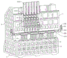
As shown in fig. 1, the freely combinable flexible bending center comprises a workbench 1, a number supplementing presser foot assembly 2 arranged in the middle of the workbench 1, and a movable presser foot assembly 3 arranged at the bottom of the workbench 1, wherein the number supplementing presser foot assembly 2 is positioned above the movable presser foot assembly 3. In this embodiment, the sheet metal work piece of treating processing can be delivered to the below of workstation 1 in the material feeding unit of bender, but movable presser foot subassembly 3 moves in workstation 1 bottom, and number of complementing presser foot subassembly 2 can carry out the independent assortment with movable presser foot subassembly 3 to the combination presser foot that forms arbitrary length fixes the sheet metal work piece, and the operation of bending can be carried out the sheet metal work piece to the bending cutting die of bender, thereby carries out the flexible processing of bending to the sheet metal work piece of different size length and angle.
As shown in fig. 1 and 3, the number supplementing presser foot assembly 2 includes a lateral moving plate 21, a plurality of lifting moving mechanisms 22, a plurality of longitudinal moving mechanisms 23, a plurality of presser foot connecting seats 24 and a plurality of number supplementing presser feet 25, two first guide rails 11 arranged in parallel are transversely arranged on the front surface of the workbench 1, first sliding blocks 211 are respectively arranged on two sides of the back of the lateral moving plate 21, and the lateral moving plate 21 is connected with the first guide rails 11 through the first sliding blocks 211. In this embodiment, the traverse plate 21 can move laterally on the working table 1, and specifically, the first slider 211 of the traverse plate 21 can move laterally along the first guide rail 11 on the working table 1.
As shown in fig. 3 and 4, the lifting/lowering mechanism 22 includes a lifting/lowering base 221 and a lifting/lowering driving mechanism 222, wherein a plurality of second guide rails 212 parallel to each other are disposed on the front surface of the lateral moving plate 21 in the vertical direction, second sliders 2211 are disposed on both sides of the back of the lifting/lowering base 221, the lifting/lowering base 221 is connected to the two second guide rails 212 through the second sliders 2211, the lifting/lowering driving mechanism 222 is disposed on the top of the lateral moving plate 21, and the movable end of the lifting/lowering driving mechanism 222 is connected to the lifting/lowering base 221. In this embodiment, the lifting driving mechanism 222 can drive the lifting moving base 221 to move up and down on the lateral moving plate 21. Specifically, the second slider 2211 of the vertically movable base 221 is vertically movable along the second guide rail 212 of the lateral movable plate 21.
Further, the lifting driving mechanism 222 is one of a motor driving mechanism, a cylinder driving mechanism, or a hydraulic driving mechanism.
As shown in fig. 4, the lifting driving mechanism 222 is a cylinder driving mechanism, the cylinder driving mechanism 222 includes a cylinder housing 2221 and a rod guide cylinder 2222, the cylinder housing 2221 is disposed on the top of the lateral moving plate 21, the rod guide cylinder 2222 is disposed on the cylinder housing 2221, and the piston end of the rod guide cylinder 2222 is connected to the lifting moving base 221. In this embodiment, when the rod guide cylinder 2222 is moved outward, the lifting moving base 221 is driven to move downward, and when the rod guide cylinder 2222 is retracted, the lifting moving base 221 is driven to move upward.
As shown in fig. 3, the vertical movement mechanism 23 is provided on the vertical movement base 221, the top of the presser foot connecting base 24 is connected to the vertical movement mechanism 23, and the bottom of the presser foot connecting base 24 is connected to the number-complementing presser foot 25. In this embodiment, the number-complementing presser foot 25 is connected to the presser foot connecting seat 24, and the number-complementing presser foot 25 can be moved longitudinally by the longitudinal moving mechanism 23.
As shown in fig. 4, further, the longitudinal moving mechanism 23 includes a fixing plate 231, two third guide rails 232, two third sliders 233 and a sliding table cylinder 234, the third guide rails 232 are respectively disposed on two sides of the bottom of the lifting moving seat 221, the third sliders 233 are disposed on two sides of the top of the fixing plate 231, the fixing plate 231 is connected to the third guide rails 232 through the third sliders 233, the sliding table cylinder 234 is disposed on the top of the lifting moving seat 221, a through groove (not shown) is disposed in the middle of the lifting moving seat 221, a sliding table of the sliding table cylinder 234 passes through the through groove to be connected to the top of the fixing plate 231, and the bottom of the fixing plate 231 is connected to the presser foot connecting seat. In this embodiment, the presser foot connecting seat 24 is connected to the fixing plate 231, and under the action of the sliding table cylinder 234, the presser foot connecting seat 24 can be driven to move longitudinally along the direction of the third guide rail 232, thereby realizing the longitudinal displacement of the number-complementing presser foot 25.
Further, the supplementary presser foot assembly 2 further includes a lateral driving mechanism (not shown) connected to the lateral moving plate 21. In this embodiment, the transverse driving mechanism can drive the transverse moving plate 21 to automatically move on the working table 1. It should be noted that the transverse driving mechanism may be one of a chain belt driving mechanism and an air cylinder pushing mechanism, and since the transverse driving mechanism is a commonly used prior art, the structure and driving principle of the transverse driving mechanism are not described in detail in this embodiment.
As shown in fig. 1, the movable presser foot assembly 3 includes a slide rail 31, a left movable presser foot assembly 32 and a right movable presser foot assembly 33, the slide rail 31 is disposed at the bottom of the worktable 1, the left movable presser foot assembly 32 is disposed at the left side of the slide rail 31, and the right movable presser foot assembly 33 is disposed at the right side of the slide rail 31. In this embodiment, the left moving presser foot assembly 32 and the right moving presser foot assembly 33 can be moved on the slide rail 31 respectively to adjust the gap between the left moving presser foot assembly 32 and the right moving presser foot assembly 33, and the complement presser foot assembly 2 can be moved three-dimensionally on the worktable 1 to move the complement presser foot 25 to the gap between the left moving presser foot assembly 32 and the right moving presser foot assembly 33 to realize the free combination of the presser feet.
As shown in fig. 5, the left moving presser foot assembly 32 further includes a first motor 321, a first speed reducer 322, a first lead screw mounting seat 323, a first lead screw 324, a first lead screw nut seat 325, a first pull rod 326, a plurality of first guide blocks 327 and a plurality of left presser feet 328, the first lead screw mounting seat 323 is arranged at the bottom of the workbench 1 at the left side of the slide rail 31, the first lead screw 324 is sleeved on the first lead screw mounting seat 323, an output shaft of the first motor 321 is connected with a first speed reducer 322, an output end of the first speed reducer 322 is connected with a first screw rod 324, the first screw nut seat 325 is sleeved on the first screw 324, one end of the first pull rod 326 is connected with the right side of the first screw nut seat 325, the other end of the first pull rod 326 is connected with a plurality of left press feet 328 in a penetrating manner, and the top of each left press foot 328 is connected with the slide rail 31 through a first guide block 327. In this embodiment, when the position of the left presser foot 328 needs to be moved, the first motor 321 is started, the first lead screw 324 is driven to rotate by the speed reduction and torque increase of the first speed reducer 322, the first lead screw nut seat 325 is sleeved on the first lead screw 324, and then the first lead screw nut seat 325 is driven to move on the first lead screw 324, and the first pull rod 326 is connected with the first lead screw nut seat 325, so that the left presser foot 328 on the first pull rod 326 can be driven to realize lateral displacement. It should be noted that the user may also adjust the gap between the adjacent left presser feet 328 according to actual conditions.
As shown in fig. 5, the right moving presser foot assembly 33 further includes a second motor 331, a second speed reducer 332, a second lead screw mounting seat 333, a second lead screw 334, a second lead screw nut seat 335, a second pull rod 336, a plurality of second guide blocks 337 and a plurality of right presser feet 338, the second screw rod mounting seat 333 is arranged at the bottom of the workbench 1 at the right side of the slide rail 31, the second screw rod 334 is sleeved on the second screw rod mounting seat 333, an output shaft of the second motor 331 is connected with a second speed reducer 332, an output end of the second speed reducer 332 is connected with a second screw rod 334, the second screw nut seat 335 is sleeved on the second screw 334, one end of the second pull rod 336 is connected with the left side of the second screw nut seat 335, the other end of the second pull rod 336 is connected with a plurality of right press feet 338 in a penetrating way, and the top of each right press foot 338 is connected with the slide rail 31 through a second guide block 337. In this embodiment, when the position of the right presser foot 338 needs to be moved, the second motor 331 is started, the second lead screw 334 is driven to rotate by the deceleration and torque increasing effects of the second speed reducer 332, the second lead screw nut seat 335 is sleeved on the second lead screw 334, so as to drive the second lead screw nut seat 335 to move on the second lead screw 334, and the second pull rod 336 is connected with the second lead screw nut seat 335, so as to drive the right presser foot 338 on the second pull rod 336 to realize lateral displacement. It should be noted that the user may also adjust the gap between the adjacent right presser feet 338 according to actual conditions.
As shown in fig. 1 and 3, the number supplementing presser foot 25, the left presser foot 328 and the right presser foot 338 have the same structure, the bottom parts of the number supplementing presser foot 25, the left presser foot 328 and the right presser foot 338 are all provided with smooth end surfaces 200, and the middle parts of the number supplementing presser foot 25, the left presser foot 328 and the right presser foot 338 are respectively provided with a hollowed-out waist groove 201 convenient for hand-holding movement. In this embodiment, the smooth end surface 200 allows the number-complementing presser foot 25, the left presser foot 328, and the right presser foot 338 to be more attached to the surface of the sheet metal workpiece, thereby improving the accuracy of the flexible bending.
As shown in fig. 5, further, the slide rail 31 is formed by splicing sectional short rails. In the embodiment, the sliding rail 31 formed by splicing the sectional short rails is adopted, so that a user can conveniently install the presser foot with the required length according to actual requirements.
As shown in fig. 2, the present invention further comprises a base 4, a vertical frame 5 and a linear guide module 6, wherein the front surface of the vertical frame 5 is slidably connected with the back surface of the worktable 1 through the linear guide module 6, the bottom of the vertical frame 5 is fixedly connected with the base 4, a plurality of lower presser feet 41 are arranged on the side edge of the top of the base 4, and the lower presser feet 41 are arranged below the movable presser foot assembly 3. In this embodiment, the sheet metal work piece of treating processing can be placed on lower presser foot 41 on base 4, number of supplementation presser foot 25 can form the combination presser foot with left presser foot 328, right presser foot 338 independent assortment, the combination presser foot can be with sheet metal work piece butt on lower presser foot 41, under linear guide module 6's effect, can drive the whole slip that goes up and down that goes on of workstation 1, thereby realize firm fixed to the sheet metal work piece, after the fixing finishes, the operation of bending can be carried out to the sheet metal work piece to the bending die of bender, thereby realize the flexible bending processing to different sizes and angle sheet metal work piece.
By adopting the technical scheme, the sheet metal workpiece to be processed can be placed on the lower presser foot of the base, the left movable presser foot assembly and the right movable presser foot assembly can respectively realize automatic transverse movement at the bottom of the workbench to adjust the gap between the left movable presser foot assembly and the right movable presser foot assembly, the number supplementing presser foot assembly can perform three-dimensional movement on the workbench to move the number supplementing presser foot to the gap between the left movable presser foot assembly and the right movable presser foot assembly to perform free adjustment and combination, and a user can also respectively adjust the number and the arrangement gap of the left presser foot and the right presser foot according to actual requirements, so that combined presser feet with any length can be realized, the sheet metal workpiece can be pressed and fixed by the combined presser foot, and a bending cutter die of a bending machine can perform bending operation on the sheet metal workpiece, so that flexible bending processing on sheet metal workpieces with different sizes and angles can be realized; the whole design is reasonable, the free combination is convenient, the processing efficiency is high, the automation degree is high, and the machine can be popularized and used.
The present invention is not limited to the above preferred embodiments, and any modifications, equivalent substitutions and improvements made within the spirit and principle of the present invention should be included in the protection scope of the present invention.