CN110051461B - Orthopedics traction frame for medical orthopedics - Google Patents
Orthopedics traction frame for medical orthopedics Download PDFInfo
- Publication number
- CN110051461B CN110051461B CN201910483522.4A CN201910483522A CN110051461B CN 110051461 B CN110051461 B CN 110051461B CN 201910483522 A CN201910483522 A CN 201910483522A CN 110051461 B CN110051461 B CN 110051461B
- Authority
- CN
- China
- Prior art keywords
- groove
- support
- plate
- connecting rod
- rotating
- Prior art date
- Legal status (The legal status is an assumption and is not a legal conclusion. Google has not performed a legal analysis and makes no representation as to the accuracy of the status listed.)
- Active
Links
Images


Classifications
-
- A—HUMAN NECESSITIES
- A61—MEDICAL OR VETERINARY SCIENCE; HYGIENE
- A61F—FILTERS IMPLANTABLE INTO BLOOD VESSELS; PROSTHESES; DEVICES PROVIDING PATENCY TO, OR PREVENTING COLLAPSING OF, TUBULAR STRUCTURES OF THE BODY, e.g. STENTS; ORTHOPAEDIC, NURSING OR CONTRACEPTIVE DEVICES; FOMENTATION; TREATMENT OR PROTECTION OF EYES OR EARS; BANDAGES, DRESSINGS OR ABSORBENT PADS; FIRST-AID KITS
- A61F5/00—Orthopaedic methods or devices for non-surgical treatment of bones or joints; Nursing devices; Anti-rape devices
- A61F5/01—Orthopaedic devices, e.g. splints, casts or braces
- A61F5/04—Devices for stretching or reducing fractured limbs; Devices for distractions; Splints
- A61F5/042—Devices for stretching or reducing fractured limbs; Devices for distractions; Splints for extension or stretching
Landscapes
- Health & Medical Sciences (AREA)
- Nursing (AREA)
- Orthopedic Medicine & Surgery (AREA)
- Engineering & Computer Science (AREA)
- Biomedical Technology (AREA)
- Heart & Thoracic Surgery (AREA)
- Vascular Medicine (AREA)
- Life Sciences & Earth Sciences (AREA)
- Animal Behavior & Ethology (AREA)
- General Health & Medical Sciences (AREA)
- Public Health (AREA)
- Veterinary Medicine (AREA)
- Orthopedics, Nursing, And Contraception (AREA)
Abstract
The invention relates to the technical field of medical treatment, and discloses an orthopedic traction frame for medical orthopedics, which comprises a support, a rotating mechanism and a rotating mechanism, wherein a foot stand and a clamping plate which can freely rotate and change angles are arranged on the support, the position of the leg of a user can be changed at multiple angles, the traction frame is convenient for the user to use, a transverse plate I which can rotate and fix the angle is arranged on the support, the posture of the user on the traction frame can be changed, a concave plate which can slide left and right and is controlled by a rotary disc is arranged on the support, the concave plate is designed to be concave, the position of the hip of the user on the support can be conveniently adjusted by the user, the position of a thigh is changed, the concave plate can limit the movement of the hip of the user, the working surfaces of the transverse plate I and the transverse plate II are designed to be soft materials and are more fit with the adaptive environment of the human body, and six uniformly distributed supporting rods are arranged on the lower side of the support, the stability of support is improved, this traction frame of better use is guaranteed.
Description
Technical Field
The invention relates to the technical field of medical treatment, in particular to an orthopedic traction frame for medical orthopedics.
Background
Bone traction is one of orthopedic treatment methods for reduction and fixation of fracture and other orthopedic diseases, particularly for patients who are not suitable for operation, the treatment purpose can be achieved through traction, for patients who have fracture of lower legs or other lower limb diseases, because the lower limbs are difficult to move, a posture is kept for a long time, the lower limb rehabilitation is not facilitated, joint stiffness, muscle spasm and even skin necrosis are easily caused, the lower limb rehabilitation of the patients is usually assisted through a traction frame clinically, traction nursing is to achieve rehabilitation and maintenance reduction of fracture or dislocation by using proper continuous traction force and counter traction force, the patients are often required to be subjected to traction for correcting postoperative bones or treating other aspects, sometimes even continuous bone traction is required, and various nursing such as dressing change and cleaning are carried out on wounds of the patients while traction nursing, the invention provides a novel traction frame, which achieves the effect of providing better traction treatment for a user by adjusting the posture, the hip position and the leg position of the user.
Disclosure of Invention
Technical problem to be solved
Aiming at the defects of the prior art, the invention provides an orthopedic traction frame for medical orthopedics, which has the advantages of convenience in use, convenience in adjustment and the like, and solves the problem of inconvenience in adjustment.
(II) technical scheme
In order to achieve the purpose of convenient adjustment, the invention provides the following technical scheme: the utility model provides an orthopedics traction frame that medical orthopedics used, includes support, slewing mechanism, diaphragm one, diaphragm two and concave plate, slewing mechanism has eight, every slewing mechanism comprises a bearing frame and a bearing one, the inner circle of bearing one can the free rotation, diaphragm one is installed to the upside of support, and open on the left side of support has a recess one, recess one is a recess and the punch combination that runs through the support, is equipped with a pinion rack in the recess one, the pinion rack is the arc that has the gear, and the shape and the size of pinion rack are the looks adaptation with recess one, the upper end fixed connection of pinion rack is to one of diaphragm one, the other end of diaphragm one passes through pole swing joint to two slewing mechanism, two slewing mechanism fixed connection to the support, guarantee to rotate through slewing mechanism, utilize the fixed action of pinion rack and recess one, the transverse plate can be fixed by a rotation angle, so that a user can lie down or sit up, and the traction frame is convenient for the user to use.
Preferably, six supporting rods are installed on the lower side of the support and used for stabilizing the support, stability of the support is guaranteed, and a user can use the traction frame conveniently.
Preferably, the upper surface of the bracket is further provided with two second grooves and a hole on the right side of the rotating mechanism connected with the first transverse plate, the two rotating mechanisms are installed between the second grooves and the hole of the bracket, the two rotating mechanisms are corresponding in position, a sliding block is placed in each of the two second grooves and can slide in the groove, the top end of the sliding block is fixed to the lower side of the concave plate, a gear groove is formed in the corresponding position of each sliding block, the gear groove is a groove with a gear, a gear is arranged in each gear groove, the gear grooves and the gears of the gears can be meshed with each other to ensure that the gears can rotate in the gear grooves, a fourth connecting rod is fixedly connected between the two gears and penetrates through the two rotating mechanisms, and the fourth connecting rod is fixedly connected with the first bearing to play a role in supporting the fixed gears and the fourth connecting rod, a pulley is fixedly arranged in the middle of the fourth connecting rod and above the hole, two rotating mechanisms, a pulley and a third connecting rod are arranged at corresponding positions on the lower side of the support in the same manner, the pulley is fixedly arranged in the middle of the hole on the third connecting rod, the third connecting rod is fixed with inner rings of two first bearings, the two pulleys are connected through a crawler, the pulley is also fixed at the other end of the third connecting rod, the pulley is provided with a crawler and connected to the second connecting rod, one end of the second connecting rod is fixedly connected to the inner ring of the second bearing, the other end of the second connecting rod is fixedly provided with a first adjusting disk, the outer ring of the second bearing is fixed on the side surface of the support to ensure that the second connecting rod and the first adjusting disk can rotate through the second bearing, the second connecting rod is also provided with a pulley and is connected with the pulley on the top end of the third connecting rod through the crawler, and the first adjusting disk is rotated to adjust the position of a user, so that the traction frame is convenient for the user to use.
Preferably, the upper surface of the concave plate of the bracket is a concave surface for limiting the movement of the buttocks of a user and facilitating the fixing of the legs of the user, and the upper surfaces of the first transverse plate and the second transverse plate are made of soft materials, so that the traction frame is more convenient to use.
Preferably, a transverse plate II is fixedly arranged on the right side of the concave plate on the upper surface of the support, four grooves are formed in the transverse plate II, a rotating mechanism is arranged in each groove and can freely rotate in the groove, the number of the rotating mechanisms is four, each rotating mechanism comprises a rotary plate I, a rotary groove is formed in the edge of each rotary plate I, a rotary plate II is arranged in each rotary groove and can freely rotate in the rotary groove, a clamping plate is fixedly arranged on each of the two rotating mechanisms close to one side of the concave plate and is fixedly connected with the rotary plate II, the position and the angle of the clamping plate on the transverse plate II can be changed by utilizing the rotating effect of the rotary plate I and the rotary plate II, the effect of more convenient use is achieved, and a rotating mechanism is fixed on each of the two rotary plates II in the other two rotating mechanisms, an inner ring of a bearing I in the rotating mechanism is fixedly connected with a connecting rod I, one end of the connecting rod I is fixedly connected with an adjusting disc II, and the other end of the connecting rod I is fixedly provided with a foot rest.
Preferably, the splint is a groove-shaped block, two air bags are arranged at corresponding positions of the groove of the splint, the legs of a user are fixed by the air bags, and the user is not injured.
Preferably, the foot rest is the semi-open type block that four boards are constituteed, and the opening is two adjacent faces, places user's foot in the foot rest, through rotating adjustment disk two reaches the effect of rotating the foot rest, and utilizes the rotation effect of carousel one and carousel two reaches the effect that changes position and angle of foot rest on diaphragm two, more facilitates the user and uses.
(III) advantageous effects
Compared with the prior art, the invention provides an orthopedic traction frame for medical orthopedics, which has the following beneficial effects:
1. this orthopedics traction frame that medical treatment orthopedics was used, it is through installing a free rotation and foot rest and the splint that change the angle on the support, can the position of multi-angle change user's shank, the person of facilitating the use uses this traction frame.
2. This orthopedics traction frame that medical orthopedics was used through the diaphragm one of installing one can rotate and fixed angle on the support, can change the posture of user on this traction frame, more makes things convenient for the user to use this traction frame.
3. This orthopedics traction frame that medical treatment orthopedics was used, through installing a recess board that can utilize the horizontal slip of carousel control on the support, and the recess board design is interior concave type, and the person of facilitating the use adjusts the position of buttock on the support, changes the position of thigh, and interior concave type recess board, can restrict the removal of user's buttock, better regulation and use this traction frame.
4. This orthopedics traction frame that medical treatment orthopedics was used, through the working face design with diaphragm one and diaphragm two for soft material, the human adaptation environment of more laminating, this traction frame of better use.
5. This orthopedics traction frame that medical treatment orthopedics was used, through the bracing piece of six evenly distributed of downside installation at the support, improve the stability of support, guarantee this traction frame of better use.
Drawings
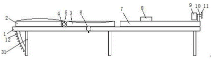
FIG. 1 is a front view of the present invention;
FIG. 2 is a side view of the present invention;
fig. 3 is a schematic view of the structure and position of the toothed plate of the present invention;
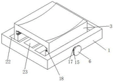
FIG. 4 is a schematic view of the position of the concave plate of the present invention;
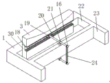
FIG. 5 is a schematic rear view of the concave plate of the present invention;
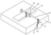
FIG. 6 is a schematic view of the connection of the internal structure of the concave plate according to the present invention;
FIG. 7 is a schematic view of a splint according to the present invention;
FIG. 8 is a schematic view of a connection of an adjusting plate according to the present invention;
FIG. 9 is a schematic view of the turning mechanism of the present invention;
fig. 10 is a schematic view of a rotating mechanism according to the present invention.
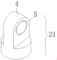
In the figure: the device comprises a support 1, a first transverse plate 2, a first concave plate 3, a first bearing seat 4, a first bearing 5, a first adjusting plate 6, a second transverse plate 7, a clamping plate 8, a foot rest 9, a first connecting rod 10, a second adjusting plate 11, a toothed plate 12, a first groove 13, an air bag 14, a second connecting rod 15, a pulley 16, a second bearing 17, a gear groove 18, a gear 19, a fourth connecting rod 20, a rotating mechanism 21, a second groove 22, a hole 23, a crawler 24, a third connecting rod 25, a rotating mechanism 26, a first rotating disc 27, a rotating groove 28, a second rotating disc 29, a sliding block 30 and a supporting rod 31.
Detailed Description
The technical solutions in the embodiments of the present invention will be clearly and completely described below with reference to the drawings in the embodiments of the present invention, and it is obvious that the described embodiments are only a part of the embodiments of the present invention, and not all of the embodiments. All other embodiments, which can be derived by a person skilled in the art from the embodiments given herein without making any creative effort, shall fall within the protection scope of the present invention.
Referring to fig. 1-10, an orthopedic traction frame for medical orthopedics comprises a support 1, four pulleys 16, eight rotating mechanisms 21, a track 24 and a rotating mechanism 26, wherein the number of the pulleys 16 is four, the number of the rotating mechanisms 21 is eight, the rotating mechanism 21 comprises a bearing seat 4 and a bearing I5, an inner ring of the bearing I5 can rotate freely, six support rods 31 are mounted on the lower side of the support 1, the support rods 31 are used for stabilizing the support 1 and ensuring the stability of the support 1, a transverse plate I2, a concave plate 3 and a transverse plate II 7 are sequentially mounted on the upper side of the support 1, the upper surfaces of the transverse plate I2 and the transverse plate II 7 are designed to be made of soft materials, a groove I13 is formed on the left side of the support 1, the groove I13 is a groove and a hole penetrating through the support 1, specifically, as shown in fig. 3, a toothed plate 12 is arranged in the groove I13, the toothed plate 12 is an arc-shaped plate with a gear, the shape and the size of the toothed plate 12 are matched with the first groove 13, the upper end of the toothed plate 12 is fixedly connected to one end of the first transverse plate 2, the other end of the first transverse plate 2 is movably connected to the two rotating mechanisms 21 through a rod, the two rotating mechanisms 21 are fixedly connected to the support 1, it is guaranteed that the toothed plate 2 can rotate through the rotating mechanisms 21, and the rotating angle of the first transverse plate 2 can be fixed by utilizing the fixing effect of the toothed plate 12 and the first groove 13.
The upper surface of the support 1 is further provided with two grooves 22 and a hole 23 on the right side of the rotating mechanism 21 connected with the transverse plate I2, the two rotating mechanisms 21 are installed in the middle of the two grooves 22 and the hole 23 of the support 1, the two rotating mechanisms 21 are corresponding in position, a sliding block 30 is placed in each of the two grooves 22 and can slide in the groove 22, the top end of the sliding block 30 is fixed to the lower side of the concave plate 3, a gear groove 18 is formed in the corresponding position of each of the two sliding blocks 30, the gear groove 18 is a groove with a gear, a gear 19 is arranged in each gear groove 18, the gears of the gear grooves 18 and the gear 19 can be meshed with each other, the gear 19 can rotate in the gear groove 18, a connecting rod IV 20 is fixedly connected between the two gears 19, and the connecting rod IV 20 penetrates through the two rotating mechanisms 21, and the four connecting rods 20 are fixedly connected with the first bearing 5 and play a role of supporting the fixed gear 19 and the four connecting rods 20, a pulley 16 is fixedly arranged in the middle of the four connecting rods 20 and above the hole 23, two rotating mechanisms 21, a pulley 16 and a three connecting rods 25 are arranged at corresponding positions on the lower side of the bracket 1 in the same way, a pulley 16 is fixedly arranged on the three connecting rods 25 at the middle of the hole 23, the three connecting rods 25 are fixed with the inner rings of the two first bearing 5, the two pulleys 16 are connected through a crawler 24, the other end of the three connecting rods 25 is also fixed with a pulley 16, the pulley 16 is provided with a crawler 24 and connected to the two connecting rods 15, one end of the two connecting rods 15 is fixedly connected to the second bearing 17, the other end of the two connecting rods 15 is fixed with a first adjusting disc 6, and the outer rings of the two bearing 17 are fixed on the side surface of the bracket 1, the two connecting rods 15 and the first adjusting disk 6 can rotate by utilizing the second bearing 17, the pulley 16 is also arranged on the second connecting rod 15 and is connected with the pulley 16 on the top end of the third connecting rod 25 through the crawler 24, when the first adjusting disk 6 is rotated, the gear 19 is ensured to rotate in the gear groove 18 through the rotating effects of the four pulleys 16, the four rotating mechanisms 21 and the two crawler 24, so that the sliding block 30 can slide left and right in the second groove 22, the sliding block 30 drives the concave plate 3 to move left and right for adjusting the position of a user, and the upper surface of the concave plate 3 of the bracket 1 is a concave surface, so that the use of the user is facilitated.
The upper surface of the bracket 1 is fixedly provided with a transverse plate II 7 at the right side of the concave plate 3, the transverse plate II 7 is provided with four grooves, each groove is internally provided with a rotating mechanism 26, the rotating mechanisms 26 can freely rotate in the grooves, the number of the rotating mechanisms 26 is four, each rotating mechanism 26 comprises a rotary plate I27, the edge of each rotary plate I27 is provided with a rotary groove 28, each rotary groove 28 is internally provided with a rotary plate II 29, the rotary plate II 29 can freely rotate in the rotary groove 28, two rotating mechanisms 26 close to one side of the concave plate 3 are fixedly provided with a clamping plate 8, the clamping plate 8 is fixedly connected with the rotary plate II 29, the clamping plate 8 is a groove-shaped block body, two air bags 14 are arranged at the corresponding positions of the grooves of the clamping plate 8, and the air bags 14 are used for fixing the legs of a user, the user is not hurt, the position and the angle of the clamping plate 8 on the transverse plate II 7 can be changed by utilizing the rotating effect of the first rotating disc 27 and the second rotating disc 29, so that the effect of more convenient use is achieved, the rotating mechanisms 21 are fixed on the two rotating discs 29 in the other two rotating mechanisms 26, the inner ring of the bearing I5 in each rotating mechanism 21 is fixedly connected with the first connecting rod 10, one end of the first connecting rod 10 is fixedly connected with the second adjusting disc 11, the other end of the first connecting rod 10 is fixedly provided with the foot rest 9, the foot rest 9 is a semi-open block body formed by four plates, the opening is two adjacent surfaces, the feet of the user are placed in the foot rest 9, the effect of rotating the foot rest 9 is achieved by rotating the second adjusting disc 11, and the effect of changing the position and the angle of the foot rest 9 on the transverse plate II 7 is achieved by utilizing the rotating effect of the first rotating discs 27 and the second rotating disc 29, more convenient for the user to use.
When using, the user lies on this traction frame, through changing the position of pinion rack 12 in recess 13, reach the angle that changes diaphragm one 2, can change user's posture, rotate adjusting disk one 6, through the transmission effect of four slewing mechanism, two tracks and four pulleys, reach the effect of steady removal 3, and 3 upper surface designs of concave plate are the indent type, better buttock of placing the user, install a diaphragm two 7 on support 1, be equipped with four rotary mechanism in 7, install splint and can vertical pivoted foot rest in four rotary mechanism respectively, utilize rotary mechanism's eccentric rotation effect, reach the position and the angle that change splint and foot rest, for this traction frame of better use of user.
Although embodiments of the present invention have been shown and described, it will be appreciated by those skilled in the art that changes, modifications, substitutions and alterations can be made in these embodiments without departing from the principles and spirit of the invention, the scope of which is defined in the appended claims and their equivalents.
Claims (6)
1. The utility model provides an orthopedics traction frame that medical treatment orthopedics was used, includes support (1), slewing mechanism (21) and rotary mechanism (26), slewing mechanism (21) comprises a bearing frame (4) and a bearing (5), the inner circle ability free rotation of bearing (5), slewing mechanism (21) have eight, its characterized in that: one side of the support (1) is connected to one end of the transverse plate I (2) through two rotating mechanisms (21) and a rod, two grooves II (22) and a hole (23) are further formed in the support (1), a sliding block (30) is placed in each of the two grooves II (22), the top end of the sliding block (30) is connected to the concave plate (3), a transverse plate II (7) is further installed on the upper surface of the support (1), four grooves are formed in each transverse plate II (7), a rotating mechanism (26) is installed in each groove, the number of the rotating mechanisms (26) is four, each rotating mechanism (26) comprises a rotary plate I (27), a rotating groove (28) is formed in each rotary plate I (27), a rotary plate II (29) is arranged in each rotating groove (28), a clamping plate (8) is installed on each rotating mechanism (26), the clamping plate (8) is fixedly connected with the second rotating disc (29), the clamping plate (8) is a groove-shaped block body, two air bags (14) are arranged at positions corresponding to the grooves of the clamping plate (8), two rotating mechanisms (21) are fixed on the second rotating discs (29) in the other two rotating mechanisms (26), an inner ring of a bearing I (5) in each rotating mechanism (21) is fixedly connected with a first connecting rod (10), one end of the first connecting rod (10) is connected with a second adjusting disc (11), the other end of the first connecting rod (10) is connected with a foot rest (9), and six supporting rods (31) are mounted on the other side of the support (1);
a first groove (13) is formed in the left side of the support (1), the first groove (13) is formed by a groove and a hole penetrating through the support (1), a toothed plate (12) is arranged in the first groove (13), and the upper end of the toothed plate (12) is fixedly connected to one end of the first transverse plate (2);
a gear groove (18) is arranged at the corresponding position of each of the two sliding blocks (30), a gear (19) is arranged in each gear groove (18), the two gears (19) are connected through a four connecting rod (20), the four connecting rod (20) penetrates through the two rotating mechanisms (21), a pulley (16) is fixedly installed in the middle of the four connecting rod (20) and above the hole (23), the two rotating mechanisms (21), the pulley (16) and a three connecting rod (25) are installed at the corresponding position of the lower side of the support (1) in the same mode, the two pulleys (16) are connected through a crawler belt (24), the pulley (16) is also fixed at the other end of the three connecting rod (25), the pulley (16) is provided with the crawler belt (24) and connected to the two connecting rod (15), one end of the two connecting rod (15) is fixedly connected to the inner ring of the second bearing (17), the other end of the second connecting rod (15) is fixedly provided with a first adjusting disc (6), the outer ring of the second bearing (17) is fixedly arranged on the side face of the support (1), and the second connecting rod (15) is also provided with a pulley (16) which is connected with the pulley (16) on the top end of the third connecting rod (25) through a crawler belt (24).
2. The orthopedic traction frame for medical orthopedics department according to claim 1, characterized in that: the splint (8) is a groove-shaped block, and two air bags (14) are arranged at the corresponding positions of the groove of the splint (8).
3. The orthopedic traction frame for medical orthopedics department according to claim 2, characterized in that: the toothed plate (12) is an arc-shaped plate with a gear.
4. The orthopedic traction frame for medical orthopedics department according to claim 2, characterized in that: the shape and the size of the toothed plate (12) are matched with those of the first groove (13).
5. The orthopedic traction frame for medical orthopedics department according to claim 3, characterized in that: the gear groove (18) is a groove with a gear, and the gear groove (18) and the gear (19) can be meshed with each other.
6. The orthopedic traction frame for medical orthopedics department according to claim 3, characterized in that: the rotary groove (28) is formed in the edge of the first rotary disc (27), and the second rotary disc (29) can rotate freely in the rotary groove (28).
Priority Applications (1)
| Application Number | Priority Date | Filing Date | Title |
|---|---|---|---|
| CN201910483522.4A CN110051461B (en) | 2019-06-04 | 2019-06-04 | Orthopedics traction frame for medical orthopedics |
Applications Claiming Priority (1)
| Application Number | Priority Date | Filing Date | Title |
|---|---|---|---|
| CN201910483522.4A CN110051461B (en) | 2019-06-04 | 2019-06-04 | Orthopedics traction frame for medical orthopedics |
Publications (2)
| Publication Number | Publication Date |
|---|---|
| CN110051461A CN110051461A (en) | 2019-07-26 |
| CN110051461B true CN110051461B (en) | 2022-04-15 |
Family
ID=67325586
Family Applications (1)
| Application Number | Title | Priority Date | Filing Date |
|---|---|---|---|
| CN201910483522.4A Active CN110051461B (en) | 2019-06-04 | 2019-06-04 | Orthopedics traction frame for medical orthopedics |
Country Status (1)
| Country | Link |
|---|---|
| CN (1) | CN110051461B (en) |
Families Citing this family (1)
| Publication number | Priority date | Publication date | Assignee | Title |
|---|---|---|---|---|
| CN112206089A (en) * | 2020-10-26 | 2021-01-12 | 谢文贵 | Traction device for rehabilitation after spinal surgery |
Citations (6)
| Publication number | Priority date | Publication date | Assignee | Title |
|---|---|---|---|---|
| WO2010057873A1 (en) * | 2008-11-18 | 2010-05-27 | S.P.A.S. S.R.L. | Rehabilitation bed |
| CN105616110A (en) * | 2015-12-29 | 2016-06-01 | 中北大学 | Cam type three-freedom-degree ankle rehabilitative device |
| CN105640736A (en) * | 2015-12-04 | 2016-06-08 | 哈尔滨工程大学 | Three degree-freedom ankle rehabilitation training apparatus |
| CN106859919A (en) * | 2017-04-13 | 2017-06-20 | 合肥工业大学 | One kind can survey the healthy trainer of lower limb in real time |
| CN108888474A (en) * | 2018-05-24 | 2018-11-27 | 钟声宝 | A kind of orthopaedics massage armchair for being convenient for lift leg |
| CN109620619A (en) * | 2019-01-21 | 2019-04-16 | 郑州大学第三附属医院(河南省妇幼保健院) | A kind of leg local anaesthesia auxiliary device |
Family Cites Families (1)
| Publication number | Priority date | Publication date | Assignee | Title |
|---|---|---|---|---|
| CN109363819A (en) * | 2018-11-28 | 2019-02-22 | 刘阳 | A kind of bone traction frame |
-
2019
- 2019-06-04 CN CN201910483522.4A patent/CN110051461B/en active Active
Patent Citations (6)
| Publication number | Priority date | Publication date | Assignee | Title |
|---|---|---|---|---|
| WO2010057873A1 (en) * | 2008-11-18 | 2010-05-27 | S.P.A.S. S.R.L. | Rehabilitation bed |
| CN105640736A (en) * | 2015-12-04 | 2016-06-08 | 哈尔滨工程大学 | Three degree-freedom ankle rehabilitation training apparatus |
| CN105616110A (en) * | 2015-12-29 | 2016-06-01 | 中北大学 | Cam type three-freedom-degree ankle rehabilitative device |
| CN106859919A (en) * | 2017-04-13 | 2017-06-20 | 合肥工业大学 | One kind can survey the healthy trainer of lower limb in real time |
| CN108888474A (en) * | 2018-05-24 | 2018-11-27 | 钟声宝 | A kind of orthopaedics massage armchair for being convenient for lift leg |
| CN109620619A (en) * | 2019-01-21 | 2019-04-16 | 郑州大学第三附属医院(河南省妇幼保健院) | A kind of leg local anaesthesia auxiliary device |
Also Published As
| Publication number | Publication date |
|---|---|
| CN110051461A (en) | 2019-07-26 |
Similar Documents
| Publication | Publication Date | Title |
|---|---|---|
| KR100942968B1 (en) | A movement machine for rehabilitation medical cure | |
| CN110664584B (en) | Rehabilitation training bed | |
| AU2008357225B2 (en) | Spinal three-dimensional orthopaedic equipment | |
| CN109806050A (en) | A kind of Multifunctional orthopedics treatment traction table | |
| CN110051461B (en) | Orthopedics traction frame for medical orthopedics | |
| CN209996659U (en) | multifunctional orthopedic nursing support | |
| CN209864498U (en) | Medical orthopedic surgery posture adjusting device | |
| CN205007452U (en) | Medical care chair with roast lamp | |
| CN108837389B (en) | Medical treatment is with lumbar disc herniation patient's massage equipment of taking exercise | |
| CN114129384A (en) | Orthopedics postoperative care trainer | |
| CN213490246U (en) | Leg rehabilitation training device | |
| CN108670519A (en) | A kind of adjustable electric traction device of orthopedic rehabilitation | |
| CN112353628A (en) | Orthopedic spine correction massage device with far infrared treatment function | |
| CN204684099U (en) | The leg training elevation device that a kind of paralytic patient is special | |
| CN207640900U (en) | A kind of orthopedic rehabilitation activity auxiliary device | |
| CN113952683B (en) | Lower limb exercising device for orthopedic rehabilitation | |
| CN105232312B (en) | Hip dynamic fumigating therapeutical machine | |
| CN211157096U (en) | Orthopedics knee joint nursing activity ware | |
| CN210355301U (en) | Recovered device of taking exercise of orthopedics of angularly adjustable | |
| CN218636263U (en) | Supporting device for nursing | |
| CN220824440U (en) | Portable lower limb function exercise instrument | |
| CN108721014A (en) | A kind of Orthopaedic nursing bed being conveniently adjusted posture | |
| CN215385692U (en) | Orthopedic nursing massage rehabilitation device | |
| CN112998990B (en) | Support device for leg nursing | |
| CN217611608U (en) | Easily adjustable limb correction device for orthopedic postoperative care |
Legal Events
| Date | Code | Title | Description |
|---|---|---|---|
| PB01 | Publication | ||
| PB01 | Publication | ||
| SE01 | Entry into force of request for substantive examination | ||
| SE01 | Entry into force of request for substantive examination | ||
| GR01 | Patent grant | ||
| GR01 | Patent grant |