Disclosure of Invention
The projector described in patent document 1 can be used as an illumination device when, for example, an illumination image (for example, a monochrome image) is used as the projection image.
Even in a situation where a projector is used as an illumination device, keystone correction for ensuring visibility is required for an image requiring visibility such as an OSD menu. On the other hand, the trapezoidal distortion correction for ensuring visibility is not so much required for the illumination image, but is required for matching the projection region of the illumination image with the illumination target region (the region where the user wants to irradiate illumination light). That is, in a situation where the projector is used as an illumination device, it is required to perform different keystone corrections for the combined 2 images.
Since the projector described in patent document 1 performs the same keystone correction for the 2 combined images, it is not possible to perform different keystone corrections for the 2 combined images.
The present invention has been made in view of the above circumstances, and an object of the present invention is to provide a technique capable of performing different keystone corrections for 2 synthesized images.
One aspect of the projector according to the present invention is a projector including: a 1 st correction unit that performs 1 st correction for correcting distortion of an image on 1 st image information to generate 1 st corrected image information; a 2 nd correction unit that performs a 2 nd correction of correcting distortion of the image on the 2 nd image information to generate 2 nd corrected image information; a synthesizing unit that synthesizes the 1 st corrected image information and the 2 nd corrected image information to generate synthesized image information; and a projection unit that projects an image corresponding to the synthesized image information, wherein the 2 nd correction is different from the 1 st correction.
According to this method, different keystone corrections can be applied to the combined 2 images.
In one aspect of the projector, it is preferable that the projector further includes a correction control unit that adjusts a difference between the 1 st correction and the 2 nd correction in accordance with an operation mode of the projector.
According to this aspect, the relationship of keystone correction performed on each of the 2 images to be combined can be adapted to the operation mode.
In one aspect of the projector, it is preferable that the operation mode includes a 1 st mode and a 2 nd mode, and the correction control unit makes a difference between the 2 nd correction and the 1 st correction in the 1 st mode larger than the difference in the 2 nd mode.
According to this aspect, the projector is in a state of being more suitable for the illumination device than the display device in the 1 st mode, and is in a state of being more suitable for the display device than the illumination device in the 2 nd mode.
One aspect of the projector according to the present invention is a projector including: a 1 st distortion correcting unit that performs 1 st correction and 3 rd correction for correcting distortion of an image on 1 st image information to generate 1 st distortion corrected image information; a synthesizing unit that synthesizes the 2 nd image information and the 1 st distortion corrected image information to generate 1 st synthesized image information; a 2 nd distortion correcting unit that performs 2 nd correction for correcting distortion of an image on the 1 st synthesized image information to generate 2 nd distortion corrected image information; and a projection unit that projects an image corresponding to the 2 nd distortion corrected image information, the 2 nd correction being different from the 1 st correction, and the 3 rd correction being an inverse correction of the 2 nd correction.
According to this method, different keystone corrections can be applied to the combined 2 images.
In one aspect of the projector described above, it is preferable that the projector further includes a supply unit that supplies the 1 st image information to the 1 st distortion correction unit when an operation mode of the projector is a 1 st mode, supplies the 1 st image information to the 1 st distortion correction unit when the operation mode is a 2 nd mode without supplying the 1 st image information to the 1 st distortion correction unit, generates the 1 st composite image information in the 1 st mode, synthesizes the 1 st image information and the 2 nd image information to generate 2 nd composite image information in the 2 nd mode, generates the 2 nd distortion correction image information in the 1 st mode, and performs the 2 nd correction on the 2 nd composite image information to generate 3 rd distortion correction image information in the 2 nd mode, the projection unit projects an image corresponding to the 2 nd distortion-corrected image information in the 1 st mode, and projects an image corresponding to the 3 rd distortion-corrected image information in the 2 nd mode.
According to this aspect, the projector is in a state of being more suitable for the illumination device than the display device in the 1 st mode, and is in a state of being more suitable for the display device than the illumination device in the 2 nd mode.
One aspect of the method for controlling a projector according to the present invention is a method for controlling a projector, including: performing 1 st correction for correcting distortion of an image on 1 st image information to generate 1 st corrected image information; performing 2 nd correction for correcting distortion of the image on the 2 nd image information to generate 2 nd corrected image information; synthesizing the 1 st corrected image information and the 2 nd corrected image information to generate synthesized image information; and projecting an image corresponding to the composite image information, the 2 nd correction being different from the 1 st correction.
According to this mode, different keystone corrections can be applied to the combined 2 images.
One aspect of the method for controlling a projector according to the present invention is a method for controlling a projector, including: performing 1 st correction and 3 rd correction for correcting distortion of an image on 1 st image information to generate 1 st distortion corrected image information; synthesizing the 2 nd image information and the 1 st distortion corrected image information to generate 1 st synthesized image information; performing 2 nd correction for correcting distortion of an image on the 1 st synthesized image information to generate 2 nd distortion corrected image information; and projecting an image corresponding to the 2 nd distortion corrected image information, the 2 nd correction being different from the 1 st correction, the 3 rd correction being an inverse correction of the 2 nd correction.
According to this mode, different keystone corrections can be applied to the combined 2 images.
Detailed Description
Embodiments of the present invention will be described below with reference to the drawings. In the drawings, the dimensions and scales of the respective portions are appropriately different from those in the actual case. The embodiments described below are preferable specific examples of the present invention. Therefore, in the present embodiment, various limitations that are preferable in terms of technology are added. However, the scope of the present invention is not limited to these embodiments unless otherwise specified in the following description.
< embodiment 1 >
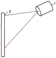
Fig. 1 is a diagram showing a projector 1 to which a 1 st embodiment of the present invention is applied. The projector 1 projects a composite image after an OSD image having characters (e.g., letters or numbers) is superimposed on a background image. The projector 1 can make the keystone correction applied to the background image and the keystone correction applied to the OSD image different from each other.
When the projector 1 is used as a display device, an image representing a character, a person, an animal, a landscape, or the like (hereinafter, also referred to as a "display image") is used as the background image. Therefore, there is a high possibility that visibility is required for both the OSD image and the background image (display image). In particular, when an image representing characters or numbers is used as the background image, readability and visibility are required in addition to visibility.
Therefore, when the projector 1 is used as a display device, it is desirable that the OSD image 3 and the background image 4 displayed on the projection surface 2 such as a wall are not distorted, that is, it is desirable that keystone correction for ensuring visibility is performed on the OSD image 3 and the background image 4, as shown in fig. 2.
On the other hand, when the projector 1 is used as an illumination device, an image representing a monochrome image or a simple pattern (hereinafter, also referred to as an "illumination image") is used as the background image, for example. Therefore, the background image (illumination image) is less likely to be required to be visible.
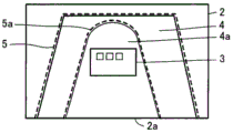
Therefore, when the projector 1 is used as an illumination device, as shown in fig. 3, it is desirable that the OSD image 3 is not distorted, but it is more desirable that the background image (illumination image) 4 is projected onto the region 5 to be illuminated than if no distortion is generated. Further, it is desirable that a specific image portion (for example, an image portion showing a spotlight shown in fig. 3) 4a shown in the background image 4 is projected to a specific area 5a (an area where a spotlight is irradiated) among the areas 5 illuminating the object.
Here, in the case where the image portion 4a is a monochrome image, the background image 4 has distortion on the projection surface 2, so that the image portion 4a becomes to have a gradation effect on the specific area 5a (an effect of becoming darker on the image portion 4a closer to the lower end 2a of the projection surface 2).
Since the projector 1 can make the keystone correction performed on the background image and the keystone correction performed on the OSD image different from each other, the projection system shown in fig. 2 and the projection system shown in fig. 3 can be supported.
Fig. 4 is a diagram schematically showing the projector 1.
The projector 1 has "illumination mode" and "display mode" as operation modes. The lighting mode is an example of the 1 st mode, and the display mode is an example of the 2 nd mode. The projector 1 includes an image information input unit 101, an input operation reception unit 102, a storage unit 103, a processing unit 104, and a projection unit 105.
The image information input unit 101 receives image information from a processing device such as a PC (personal computer). The image information indicates an image serving as a background of the OSD image. Hereinafter, the image information received by the image information input unit 101 is also referred to as "background image information". The image represented by the background image information is also referred to as a "background image". The background image information is an example of the 2 nd image information. The processing device that outputs the image information is not limited to the PC, and can be appropriately changed.
The input operation reception unit 102 is, for example, various operation buttons or a touch panel. The input operation reception unit 102 receives information (for example, an instruction to generate an OSD image, an instruction to change a distortion correction amount, and an instruction to switch an operation mode) input by a user input operation. The input operation reception unit 102 may be a remote controller or the like that transmits information corresponding to an input operation received from a user by wireless or wired transmission. In this case, the projector 1 includes a receiving unit that receives information transmitted from the remote controller. The remote controller includes various operation buttons, operation keys, and a touch panel for receiving input operations by a user.
The storage unit 103 is a computer-readable recording medium. The storage unit 103 stores a program for defining the operation of the projector 1 and various information (for example, image information, operation mode information indicating an operation mode, 1 st distortion correction amount information indicating a 1 st distortion correction amount, and 2 nd distortion correction amount information indicating a 2 nd distortion correction amount).
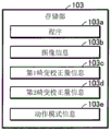
Fig. 5 is a diagram illustrating an example of the storage unit 103. In fig. 5, the storage unit 103 stores a program 103a, image information 103b, 1 st distortion correction amount information 103c, 2 nd distortion correction amount information 103d, and operation mode information 103 e.
The description returns to fig. 4. The Processing unit 104 is a computer such as a cpu (central Processing unit). The processing section 104 reads and executes the program 103a stored in the storage section 103, thereby realizing an OSD image generating section 106, keystone correction sections 107 and 108, a combining section 109, an image control section 110, and a distortion correction control section 111.
The OSD image generating unit 106 generates OSD image information indicating an OSD image having characters such as characters and numbers. The OSD image is a menu screen for displaying states of various adjustment targets (for example, contrast, brightness, and the like) of the projector 1. The OSD image may be an image different from an image having characters such as letters or numbers. In addition, it is desirable that the OSD image is an image requiring visibility. The OSD image information is an example of the 1 st image information. The OSD image generating unit 106 generates OSD image information when receiving an instruction to generate an OSD image via the input operation receiving unit 102.
The keystone correction unit 107 is an example of the 1 st correction unit. The keystone correction section 107 performs keystone correction on the OSD image information to generate 1 st corrected image information. Hereinafter, the keystone correction performed by the keystone correction unit 107 is also referred to as "1 st correction".
The keystone correction unit 108 exemplifies a 2 nd correction unit. The keystone correction unit 108 performs keystone correction on the background image information to generate 2 nd corrected image information. Hereinafter, the keystone correction performed by the keystone correction unit 108 is also referred to as "2 nd correction". The keystone correction unit 108 may perform the 2 nd correction on the image information 103b stored in the storage unit 103 to generate the 2 nd corrected image information.
The combining unit 109 combines the 1 st corrected image information and the 2 nd corrected image information to generate combined image information. The combining unit 109 generates, as combined image information, image information indicating a combined image in which an image indicated by the 1 st corrected image information (OSD image after the 1 st correction) is superimposed on an image indicated by the 2 nd corrected image information (background image after the 2 nd correction).
The image control unit 110 performs image processing on the composite image information to generate a composite image signal. For example, the image control unit 110 performs resolution conversion in which the resolution of the synthesized image information matches the resolution of the projection unit 105, and generates a synthesized image signal.
The projection unit 105 projects an image corresponding to the synthesized image signal onto the projection surface 2 (see fig. 1). The composite image signal corresponds to the composite image information.
Fig. 6 is a diagram illustrating an example of the projection unit 105. The projection unit 105 includes a light source 11, 3 liquid crystal light valves 12(12R, 12G, 12B) as an example of a light modulation device, a projection lens 13 as an example of a projection optical system, a light valve driving unit 14, and the like. The projection unit 105 forms a projection image (image light) by modulating light emitted from the light source 11 with the liquid crystal light valve 12, and projects the projection image in an enlarged manner from the projection lens 13.
The light source 11 includes a light source unit 11a including a xenon lamp, an ultra-high pressure mercury lamp, an led (light Emitting diode), a laser light source, or the like, and a reflector 11b that reduces the variation in the direction of light emitted by the light source unit 11 a. The variation in the luminance distribution of the light emitted from the light source 11 is reduced by an unillustrated integrating optical system, and thereafter, is separated into color light components of red (R), green (G), and blue (B) as the 3 primary colors of the light by an unillustrated color separating optical system. R, G, B are incident on the liquid crystal light valves 12R, 12G, and 12B, respectively.
The liquid crystal light valve 12 is constituted by a liquid crystal panel or the like in which liquid crystal is sealed between a pair of transparent substrates. A rectangular pixel region 12a including a plurality of pixels 12p arranged in a matrix is formed in the liquid crystal light valve 12, and a drive voltage can be applied to the liquid crystal for each pixel 12 p. After the light valve driving section 14 applies a driving voltage corresponding to the composite image signal input from the image control section 110 to each pixel 12p, each pixel 12p is set to a light transmittance corresponding to the composite image signal. Therefore, the light emitted from the light source 11 is transmitted through the pixel region 12a and modulated, and an image corresponding to the composite image signal is formed for each color light.
The images of the respective colors are combined for each pixel 12p by a color combining optical system (not shown) to generate a projection image as a color image (color image light). The projection image is enlarged and projected onto the projection surface 2 by the projection lens 13.
Returning to fig. 4, the distortion correction control unit 111 controls the 1 st correction (keystone correction performed by the keystone correction unit 107) and the 2 nd correction (keystone correction performed by the keystone correction unit 108).
The distortion correction control unit 111 receives the 1 st distortion correction amount information 103c from the input operation reception unit 102, and then stores the 1 st distortion correction amount information 103c in the storage unit 103. The 1 st distortion correction amount indicated by the 1 st distortion correction amount information 103c is a distortion correction amount for reducing distortion of an image projected onto the projection surface 2.
The distortion correction control unit 111 receives the 2 nd distortion correction amount information 103d from the input operation reception unit 102, and then stores the 2 nd distortion correction amount information 103d in the storage unit 103. The 2 nd distortion correction amount indicated by the 2 nd distortion correction amount information 103d is a distortion correction amount for adjusting the background image 4 (see fig. 3) projected on the projection surface 2 so as to fit the region 5 to be illuminated. The 2 nd distortion correction amount information 103d is different from the 1 st distortion correction amount information 103 c. Therefore, the keystone correction corresponding to the 2 nd distortion correction amount information 103d is different from the keystone correction corresponding to the 1 st distortion correction amount information 103 c.
Upon receiving an instruction to switch the operation mode from the input operation reception unit 102, the distortion correction control unit 111 updates the operation mode information 103e stored in the storage unit 103 to switch the operation mode. For example, when receiving an instruction to switch the operation mode in a situation where the operation mode information 103e indicates the illumination mode, the distortion correction control unit 111 switches the operation mode indicated by the operation mode information 103e from the illumination mode to the display mode.
The distortion correction control unit 111 controls the 1 st correction and the 2 nd correction using the 1 st distortion correction amount information 103c and the 2 nd distortion correction amount information 103 d. The distortion correction control unit 111 adjusts the difference between the 1 st correction and the 2 nd correction according to the operation mode of the projector 1 by using the 1 st distortion correction amount information 103c and the 2 nd distortion correction amount information 103 d. For example, the distortion correction control unit 111 makes the difference between the 1 st correction and the 2 nd correction in the illumination mode larger than the difference between the 1 st correction and the 2 nd correction in the display mode.
Next, the operation will be described. Next, the input operation reception unit 102 receives an instruction to generate an OSD image, and the OSD image generation unit 106 generates OSD image information. The image information input unit 101 is configured to receive display image information indicating a display image in the display mode and illumination image information indicating an illumination image in the illumination mode.
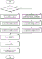
Fig. 7 is a flowchart for explaining the operation of the projector 1.
When the operation mode information 103e indicates the display mode (yes in step S1), the distortion correction control unit 111 reads the 1 st distortion correction amount information 103c from the storage unit 103. Next, the distortion correction control section 111 sets the 1 st distortion correction amount information 103c to the keystone correction sections 107 and 108 (step S2).
After setting the 1 st distortion correction amount information 103c, the keystone correction section 107 performs keystone correction corresponding to the 1 st distortion correction amount information 103c with respect to the OSD image information, and generates 1 st corrected image information (step S3).
After setting the 1 st distortion correction amount information 103c, the keystone correction unit 108 performs keystone correction corresponding to the 1 st distortion correction amount information 103c with respect to the background image information (display image information), and generates 2 nd corrected image information (step S4).
The order of step S3 and step S4 may be reversed. When the keystone correction units 107 and 108 are configured by hardware such as a circuit, step S3 and step S4 may be executed simultaneously.
Next, the combining unit 109 generates the combined image information indicating the combined image in which the image indicated by the 1 st corrected image information is superimposed on the image indicated by the 2 nd corrected image information (step S5). Next, the image control unit 110 performs image processing on the composite image information to generate a composite image signal (step S6). Next, the projection unit 105 projects an image corresponding to the synthesized image signal onto the projection surface 2 (step S7).
In the display mode, the 1 st distortion correction amount information 103c is set in the keystone correction sections 107 and 108, and thus keystone correction for ensuring visibility (distortion correction for reducing distortion of an image projected onto the projection surface 2) is performed for the OSD image and the background image. Therefore, for example, as shown in fig. 2, an OSD image 3 and a background image (display image) 4 which are not distorted are displayed on the projection surface 2.
On the other hand, when the operation mode information 103e indicates the illumination mode (no in step S1), the distortion correction control unit 111 reads the 1 st distortion correction amount information 103c and the 2 nd distortion correction amount information 103d from the storage unit 103. Next, the distortion correction control unit 111 sets the 1 st distortion correction amount information 103c to the keystone correction unit 107 and sets the 2 nd distortion correction amount information 103d to the keystone correction unit 108 (step S8).
After setting the 1 st distortion correction amount information 103c, the keystone correction section 107 performs keystone correction corresponding to the 1 st distortion correction amount information 103c with respect to the OSD image information, and generates 1 st corrected image information (step S9).
After setting the 2 nd distortion correction amount information 103d, the keystone correction unit 108 performs keystone correction corresponding to the 2 nd distortion correction amount information 103d with respect to the background image information (illumination image information), and generates 2 nd corrected image information (step S10). The order of step S9 and step S10 may be reversed. When the keystone correction units 107 and 108 are configured by hardware such as a circuit, step S9 and step S10 may be executed simultaneously. Next, steps S5 to S7 are performed.
In the illumination mode, the 1 st distortion correction amount information 103c is set in the keystone correction section 107, and the 2 nd distortion correction amount information 103d is set in the keystone correction section 108. Therefore, keystone correction (distortion correction for reducing distortion of an image projected on the projection surface 2) for ensuring visibility is performed on the OSD image, and distortion correction for matching the image projected on the projection surface 2 with the region 5 to be illuminated is performed on the background image. Therefore, for example, as shown in fig. 3, an OSD image 3 without distortion and a background image (illumination image) 4 of an area 5 corresponding to an illumination target are displayed on the projection surface 2.
According to the projector 1 and the control method of the projector 1 of the present embodiment, different keystone corrections can be applied to the 2 images (background image and OSD image) to be synthesized. Therefore, even if the projector 1 is used as an illumination device, the area to be illuminated can be illuminated while displaying the OSD image with less distortion.
The 1 st distortion correction amount information 103c is used for the keystone correction of the OSD image regardless of the operation mode. On the other hand, for the keystone correction of the background image, the 1 st distortion correction amount information 103c is used in the display mode, and the 2 nd distortion correction amount information 103d is used in the illumination mode. This means that the distortion correction control section 111 makes the difference between the 1 st correction and the 2 nd correction in the illumination mode larger than the difference between the 1 st correction and the 2 nd correction in the display mode.
According to the present embodiment, it is possible to control the change of the keystone correction according to the type of the background image (for example, the display image with characters and the illumination image without characters).
After the operation mode is switched from the display mode to the illumination mode, the keystone correction unit 108 switches the correction for the background image information from the correction using the 1 st distortion correction amount information 103c to the correction using the 2 nd distortion correction amount information 103 d.
Then, after the operation mode is switched from the illumination mode to the display mode, the keystone correction unit 108 switches the correction for the background image information from the correction using the 2 nd distortion correction amount information 103d to the correction using the 1 st distortion correction amount information 103c that has been set in the keystone correction unit 107.
Even if the operation mode is switched, the keystone correction unit 107 maintains the correction using the 1 st distortion correction amount information 103 c.
< embodiment 2 >
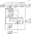
Fig. 8 is a diagram schematically showing a projector 1A to which embodiment 2 of the present invention is applied. The projector 1A has a "display mode" and an "illumination mode" as operation modes, and functions as a display device and an illumination device, and projects a composite image in which an OSD image is superimposed on a background image, as in the projector 1.
The projector 1A differs from the projector 1 in the program stored in the storage unit 103, in that the processing unit 104 differs in the functional units realized by executing the program, and in that the storage unit 103 also stores the 3 rd distortion correction amount information used for the inverse correction of the trapezoidal distortion correction corresponding to the 2 nd distortion correction amount information 103 d. Next, the projector 1A will be described centering on differences from the projector 1.
In the projector 1A, the processing unit 104 implements the OSD image generating unit 106, the image control unit 110, the supply unit 112, the distortion correcting unit 113, the image synthesizing unit 114, and the distortion correcting unit 115 by executing a program stored in the storage unit 103. The supply section 112 includes switches 116 and 117 and a correction control section 118. The distortion correction unit 113 includes an inverse correction unit 119 and a keystone correction unit 120.
In the illumination mode, the supply unit 112 supplies the OSD image information to the distortion correction unit 113 without supplying it to the image synthesis unit 114. In the display mode, the supply unit 112 supplies the OSD image information to the image combining unit 114 without supplying the OSD image information to the distortion correcting unit 113.
The switch 116 is provided between the OSD image generation section 106 and the distortion correction section 113. The switch 117 is provided between the OSD image generating unit 106 and the image synthesizing unit 114.
The correction control unit 118 turns on the switch 116 and turns off the switch 117 in the illumination mode, and turns off the switch 116 and turns on the switch 117 in the display mode. The correction control unit 118 reads the 1 st distortion correction amount information 103c, the 2 nd distortion correction amount information 103d, and the 3 rd distortion correction amount information from the storage unit 103, sets the 1 st distortion correction amount information 103c to the keystone correction unit 120, the 2 nd distortion correction amount information 103d to the distortion correction unit 115, and the 3 rd distortion correction amount information to the inverse correction unit 119.
The distortion correcting section 113 exemplifies a 1 st distortion correcting section. In the illumination mode, the distortion correction unit 113 performs the keystone correction corresponding to the 1 st distortion correction amount information 103c and the keystone correction corresponding to the 3 rd distortion correction amount information with respect to the OSD image information.
The inverse correction section 119 performs keystone correction corresponding to the 3 rd distortion correction amount information with respect to the OSD image information. The keystone correction corresponding to the 3 rd distortion correction amount information is an example of the 3 rd correction. The 3 rd correction is an inverse correction of the keystone correction performed in the distortion correcting section 115.
The keystone correction unit 120 performs keystone correction corresponding to the 1 st distortion correction amount information 103c on the output (OSD image information after the 3 rd correction) of the inverse correction unit 119 to generate 1 st distortion corrected image information. The keystone correction corresponding to the 1 st distortion correction amount information 103c is an example of the 1 st correction.
The image combining unit 114 combines the background image information and the 1 st distortion correction image information in the illumination mode to generate the 1 st combined image information, and combines the background image information and the OSD image information in the display mode to generate the 2 nd combined image information.
The distortion correcting section 115 exemplifies a 2 nd distortion correcting section. The distortion correcting section 115 performs trapezoidal distortion correction corresponding to the 2 nd distortion correction amount information 103d for the 1 st synthesized image information in the illumination mode to generate 2 nd distortion corrected image information. The keystone correction corresponding to the 2 nd distortion correction amount information is an example of the 2 nd correction. The distortion correcting section 115 performs trapezoidal distortion correction corresponding to the 2 nd distortion correction amount information 103d for the 2 nd synthetic image information in the display mode to generate 3 rd distortion corrected image information.
The image control unit 110 performs image processing on the distortion corrected image information (the 2 nd distortion corrected image information and the 3 rd distortion corrected image information) output from the distortion correcting unit 115 to generate a composite image signal. The projection unit 105 projects an image corresponding to the synthesized image signal generated by the image control unit 110 onto the projection surface 2.
Next, the operation will be described.
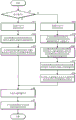
Fig. 9 is a flowchart for explaining the operation of the projector 1A. Next, it is assumed that the 1 st distortion correction amount information 103c is set in the keystone correction unit 120, the 2 nd distortion correction amount information 103d is set in the distortion correction unit 115, the 3 rd distortion correction amount information is set in the inverse correction unit 119, and the OSD image generation unit 106 generates OSD image information.
When the operation mode information 103e indicates the display mode (yes in step S1), the correction controller 118 turns off the switch 116 and turns on the switch 117 (step S11). Therefore, the OSD image information is output from the OSD image generation unit 106 to the image synthesis unit 114 via the switch 117.
The image combining unit 114 combines the background image information and the OSD image information to generate the 2 nd combined image information (step S12). Next, the distortion correcting section 115 performs trapezoidal distortion correction corresponding to the 2 nd distortion correction amount information 103d with respect to the 2 nd synthetic image information to generate 3 rd distortion corrected image information (step S13). Next, the image control unit 110 performs image processing on the distortion-corrected image information output from the distortion correction unit 115 to generate a composite image signal (step S6). Next, the projection unit 105 projects an image corresponding to the synthesized image signal generated by the image control unit 110 onto the projection surface 2 (step S7).
On the other hand, when the operation mode information 103e indicates the illumination mode (no in step S1), the correction control unit 118 turns on the switch 116 and turns off the switch 117 (step S14). Therefore, the OSD image information is output from the OSD image generation unit 106 to the inverse correction unit 119 via the switch 116.
The inverse correction section 119 performs keystone correction (inverse correction) corresponding to the 3 rd distortion correction amount information with respect to the OSD image information (step S15). Next, the keystone correction unit 120 performs keystone correction corresponding to the 1 st distortion correction amount information 103c on the output of the inverse correction unit 119 to generate 1 st distortion corrected image information (step S16). Next, the image combining unit 114 combines the background image information and the 1 st distortion corrected image information to generate the 1 st combined image information (step S17). Next, the distortion correcting section 115 performs trapezoidal distortion correction corresponding to the 2 nd distortion correction amount information 103d with respect to the 1 st synthetic image information to generate 2 nd distortion corrected image information (step S18). Thereafter, step S6 to step 7 are executed.
According to the present embodiment, different keystone corrections can be applied to the 2 images (background image and OSD image) to be combined. Therefore, even if the projector 1A is used as an illumination device, the area to be projected can be illuminated while displaying the OSD image with less distortion.
< modification example >
The present invention is not limited to the above embodiment, and various modifications described below can be made, for example. Further, one or more modifications arbitrarily selected from the modifications described below can be combined as appropriate.
< modification 1 >
In each embodiment, the distortion correction control unit 111 and the correction control unit 118 change the relationship (hereinafter referred to as "correction relationship") between the keystone correction performed on the OSD image and the keystone correction performed on the background image in accordance with the operation mode.
However, the distortion correction control unit 111 or the correction control unit 118 may change the correction relationship according to a condition different from the operation mode. For example, the distortion correction control unit 111 or the correction control unit 118 may change the correction relationship according to the content indicated by the background image (for example, whether or not the background image has a word). For example, the distortion correction control unit 111 or the correction control unit 118 sets the correction relationship to be the same as the display mode when the background image has a word, and sets the correction relationship to be the same as the illumination mode when the background image does not have a word. In this case, identification information indicating whether or not the background image has a character is added to the background image, and the distortion correction control unit 111 or the correction control unit 118 switches the operation mode between the illumination mode and the display mode based on the identification information.
< modification 2 >
All or part of the elements realized by the processing unit 104 by executing the program may be realized by hardware via an electronic circuit such as an fpga (field programmable gate array) or an asic (application Specific ic), or may be realized by cooperation of software and hardware.
< modification 3 >
The projection unit 105 uses a liquid crystal light valve as the light modulation device, but the light modulation device is not limited to the liquid crystal light valve and can be modified as appropriate. For example, the light modulation device may be configured using a 3-piece reflective liquid crystal panel. The optical modulation device may have a configuration of a system using 1 liquid crystal panel, a system using 3 Digital Mirror Devices (DMD), a system using 1 digital mirror device, or the like. When only 1 liquid crystal panel or DMD is used as the light modulation device, components corresponding to the color separation optical system and the color synthesis optical system are not required. In addition to the liquid crystal panel and the DMD, a structure capable of modulating light emitted from the light source may be employed as the light modulation device.