CN108075721B - Semi-automatic solar photovoltaic panel scrubbing device - Google Patents
Semi-automatic solar photovoltaic panel scrubbing device Download PDFInfo
- Publication number
- CN108075721B CN108075721B CN201611009135.XA CN201611009135A CN108075721B CN 108075721 B CN108075721 B CN 108075721B CN 201611009135 A CN201611009135 A CN 201611009135A CN 108075721 B CN108075721 B CN 108075721B
- Authority
- CN
- China
- Prior art keywords
- water
- rope
- photovoltaic panel
- pipe
- sliding
- Prior art date
- Legal status (The legal status is an assumption and is not a legal conclusion. Google has not performed a legal analysis and makes no representation as to the accuracy of the status listed.)
- Active
Links
- 238000005201 scrubbing Methods 0.000 title claims abstract description 10
- XLYOFNOQVPJJNP-UHFFFAOYSA-N water Substances O XLYOFNOQVPJJNP-UHFFFAOYSA-N 0.000 claims abstract description 178
- 230000007246 mechanism Effects 0.000 claims abstract description 69
- 238000004140 cleaning Methods 0.000 claims abstract description 66
- 238000010438 heat treatment Methods 0.000 claims description 38
- 230000005540 biological transmission Effects 0.000 claims description 36
- 238000002347 injection Methods 0.000 claims description 16
- 239000007924 injection Substances 0.000 claims description 16
- 230000000712 assembly Effects 0.000 claims description 7
- 238000000429 assembly Methods 0.000 claims description 7
- 238000004804 winding Methods 0.000 claims description 4
- 230000002441 reversible effect Effects 0.000 claims description 3
- 239000000428 dust Substances 0.000 abstract description 14
- 238000006243 chemical reaction Methods 0.000 abstract description 5
- 239000002184 metal Substances 0.000 description 37
- 238000005507 spraying Methods 0.000 description 34
- 239000007921 spray Substances 0.000 description 14
- 230000000694 effects Effects 0.000 description 11
- 238000010248 power generation Methods 0.000 description 10
- 239000007789 gas Substances 0.000 description 9
- 238000005406 washing Methods 0.000 description 8
- 210000003608 fece Anatomy 0.000 description 7
- 241000463219 Epitheca Species 0.000 description 6
- 230000003028 elevating effect Effects 0.000 description 6
- 230000001681 protective effect Effects 0.000 description 6
- 238000001035 drying Methods 0.000 description 5
- 230000009471 action Effects 0.000 description 4
- 239000012459 cleaning agent Substances 0.000 description 4
- 238000000034 method Methods 0.000 description 4
- 230000008878 coupling Effects 0.000 description 3
- 238000010168 coupling process Methods 0.000 description 3
- 238000005859 coupling reaction Methods 0.000 description 3
- 238000007710 freezing Methods 0.000 description 3
- 230000008014 freezing Effects 0.000 description 3
- 238000009434 installation Methods 0.000 description 3
- 230000013011 mating Effects 0.000 description 3
- 238000002844 melting Methods 0.000 description 3
- 230000008018 melting Effects 0.000 description 3
- 230000008569 process Effects 0.000 description 3
- 238000010793 Steam injection (oil industry) Methods 0.000 description 2
- 238000009825 accumulation Methods 0.000 description 2
- 238000005485 electric heating Methods 0.000 description 2
- 230000006872 improvement Effects 0.000 description 2
- 239000012466 permeate Substances 0.000 description 2
- 238000007789 sealing Methods 0.000 description 2
- 230000006835 compression Effects 0.000 description 1
- 238000007906 compression Methods 0.000 description 1
- 238000010276 construction Methods 0.000 description 1
- 238000001816 cooling Methods 0.000 description 1
- 230000007547 defect Effects 0.000 description 1
- 238000010586 diagram Methods 0.000 description 1
- 238000003912 environmental pollution Methods 0.000 description 1
- 230000003203 everyday effect Effects 0.000 description 1
- 238000003780 insertion Methods 0.000 description 1
- 230000037431 insertion Effects 0.000 description 1
- 230000000149 penetrating effect Effects 0.000 description 1
- 238000003825 pressing Methods 0.000 description 1
- 238000005096 rolling process Methods 0.000 description 1
- 230000011218 segmentation Effects 0.000 description 1
- 238000003860 storage Methods 0.000 description 1
- 239000013589 supplement Substances 0.000 description 1
- 238000010408 sweeping Methods 0.000 description 1
- 230000001360 synchronised effect Effects 0.000 description 1
- 238000002834 transmittance Methods 0.000 description 1
- 239000002699 waste material Substances 0.000 description 1
Images








Classifications
-
- H—ELECTRICITY
- H02—GENERATION; CONVERSION OR DISTRIBUTION OF ELECTRIC POWER
- H02S—GENERATION OF ELECTRIC POWER BY CONVERSION OF INFRARED RADIATION, VISIBLE LIGHT OR ULTRAVIOLET LIGHT, e.g. USING PHOTOVOLTAIC [PV] MODULES
- H02S40/00—Components or accessories in combination with PV modules, not provided for in groups H02S10/00 - H02S30/00
- H02S40/10—Cleaning arrangements
-
- H—ELECTRICITY
- H02—GENERATION; CONVERSION OR DISTRIBUTION OF ELECTRIC POWER
- H02S—GENERATION OF ELECTRIC POWER BY CONVERSION OF INFRARED RADIATION, VISIBLE LIGHT OR ULTRAVIOLET LIGHT, e.g. USING PHOTOVOLTAIC [PV] MODULES
- H02S40/00—Components or accessories in combination with PV modules, not provided for in groups H02S10/00 - H02S30/00
- H02S40/10—Cleaning arrangements
- H02S40/12—Means for removing snow
-
- Y—GENERAL TAGGING OF NEW TECHNOLOGICAL DEVELOPMENTS; GENERAL TAGGING OF CROSS-SECTIONAL TECHNOLOGIES SPANNING OVER SEVERAL SECTIONS OF THE IPC; TECHNICAL SUBJECTS COVERED BY FORMER USPC CROSS-REFERENCE ART COLLECTIONS [XRACs] AND DIGESTS
- Y02—TECHNOLOGIES OR APPLICATIONS FOR MITIGATION OR ADAPTATION AGAINST CLIMATE CHANGE
- Y02E—REDUCTION OF GREENHOUSE GAS [GHG] EMISSIONS, RELATED TO ENERGY GENERATION, TRANSMISSION OR DISTRIBUTION
- Y02E10/00—Energy generation through renewable energy sources
- Y02E10/50—Photovoltaic [PV] energy
Landscapes
- Photovoltaic Devices (AREA)
Abstract
The invention discloses a semi-automatic solar photovoltaic panel scrubbing device which comprises a plurality of first supporting plates which are sequentially arranged, a first mounting plate is arranged on the upper end face of each first supporting plate, two second supporting plates are arranged on the second supporting plates, a power mechanism is arranged below the first mounting plates, a water control box and an electric control box are arranged on the bottom end faces of the second mounting plates, and the semi-automatic solar photovoltaic panel scrubbing device further comprises a cleaning assembly and a water supply source. This patent can clear away the photovoltaic board surface ice layer that sleet, snowstorm lead to fast in all weather, can also clear away foreign matter such as photovoltaic board surface dust, debris, bird excrement fast, keeps the high light transmissivity of photovoltaic board, high photoelectric conversion rate, convenient to use, with low costs, cleaning efficiency height, wash stable, wash rapidly and effectual, to water resource utilization rate high, automated control.
Description
Technical Field
The invention relates to the field of solar power generation, in particular to a semi-automatic solar photovoltaic panel scrubbing device.
Background
The photovoltaic power generation system is a power generation system which directly converts solar energy into electric energy by utilizing a photovoltaic component, and the main components of the power generation system are the photovoltaic component, a storage battery, a controller and an inverter, and the power generation system is characterized by high reliability, long service life, no environmental pollution, independent power generation and grid-connected operation, is favored by enterprise organizations of all countries, is widely applied to the field of clean energy, has very common phenomenon of dust accumulation on the surface of the photovoltaic component after long-time use, reduces the power generation efficiency of the photovoltaic panel after dust accumulation and needs to be cleaned in time, the current main mode is manual cleaning, the manual cleaning consumes long time, the cost is high, the efficiency is low, particularly, a ground photovoltaic power station, if the manual cleaning is carried out, the input manpower is huge, the efficiency of the photovoltaic panel is obviously reduced under the high temperature condition in summer, and water needs to be sprayed for cooling, the current main mode is that a water device, the spraying purpose is poor in the mode, and waste of water resources is easily caused.
At present, the atmospheric pollution condition is more and more serious, more and more dust and sundries fall on a photovoltaic panel of a photovoltaic power station every day, and the dust and the sundries are more and more difficult to remove, and the cleaning work is difficult to complete by a common cleaning method and a cleaning device. In addition, extreme weather is increasing nowadays, and especially in winter, the condition of freezing rain or snowstorm is often met. Once the freezing rain falls on the photovoltaic panel, a thick ice layer can be formed, so that the photovoltaic power station can not be used for a long time and even the photovoltaic panel is frozen. The heavy snow layer can also cause the sunlight to be shielded by the heavy snow layer, and the normal power generation work can not be finished.
Disclosure of Invention
Aiming at the defects, the invention provides the semi-automatic solar photovoltaic panel scrubbing device which can rapidly remove the ice layer on the surface of the photovoltaic panel caused by freezing rain and snowstorm, can rapidly remove dust, sundries, bird droppings and other foreign matters on the surface of the photovoltaic panel, keeps high light transmittance and high photoelectric conversion rate of the photovoltaic panel, is convenient to use, low in cost, high in cleaning efficiency, stable in cleaning, rapid in cleaning, good in effect, high in water resource utilization rate and capable of being automatically controlled.
In order to solve the problems, the semi-automatic solar photovoltaic panel scrubbing device has the structural characteristics that: the device comprises a plurality of first supporting plates which are arranged in sequence, wherein a first mounting plate is arranged on the upper end surface of each first supporting plate, a photovoltaic plate is arranged on the upper end surface of each first mounting plate, transversely extending sliding grooves are respectively arranged on the upper end surface and the lower end surface of each first mounting plate, sliding assemblies in sliding fit with the sliding grooves are arranged in the sliding grooves, the two sliding assemblies are connected together through a fixing frame arranged above the photovoltaic plate, a cleaning assembly for cleaning the photovoltaic plate is arranged on the fixing frame, the device also comprises two second supporting plates, second mounting plates are arranged on the second supporting plates, adjacent first supporting plates are connected through first connecting plates, adjacent first mounting plates are connected with second mounting plates through second connecting plates, a power mechanism is arranged below the first mounting plates, and two ends of each sliding assembly are connected with the power mechanism through ropes, the second mounting plate is provided with a guide wheel in transmission fit with the rope, the bottom end face of the second mounting plate is provided with a water control box and an electric control box, the water control box is respectively connected with the cleaning assembly and the water supply source through water pipes, and the electric control box is connected with the power mechanism, the cleaning assembly and the power supply through cables; the cleaning assembly comprises a movable frame which is arranged at the top of a fixed frame through a lifting mechanism and can move up and down, a second motor is arranged on the movable frame, a rotating pipe which extends downwards is further rotatably arranged on the movable frame, the second motor is in transmission fit with the rotating pipe through a transmission mechanism, a flow guide pipe which is in insertion fit with an inner cavity of the rotating pipe is fixedly arranged at the upper part of the movable frame, the outer wall of the flow guide pipe is in rotation seal fit with the inner wall of the rotating pipe, the upper end of the flow guide pipe is connected with a water pipe, a water tank which is communicated with the lower end of the flow guide pipe is fixedly arranged at the lower part of the rotating pipe, an erasing device which can be in erasing fit with the photovoltaic panel and can be lifted up and down is arranged at the bottom of the water tank through a switching mechanism, a cleaning device which is in contact with the surface of the photovoltaic panel is also arranged, the heating box is electrically connected with the switching mechanism through the wire connector; the lifting mechanism comprises two first electromagnetic valves vertically installed on the fixed frame at intervals, and first valve rods of the two electromagnetic valves are fixedly connected with two ends of the movable frame respectively.
In this patent, first backup pad bottom plate part is fixed subaerial, and the quantity of first support frame has a plurality of, and each first support frame transversely arranges in proper order, can confirm specific quantity according to photovoltaic power plant's actual need capacity. The upper end of the supporting part of the first supporting frame is connected with a first mounting plate in an installing mode, and a photovoltaic panel is inserted into the first mounting plate. A photovoltaic device unit is formed by the single first supporting plate, the first mounting plate and the photovoltaic plate, and a photovoltaic device group is formed by the plurality of photovoltaic device units. The second supporting plate bottom plate is fixed on the ground, the second supporting plate and a second mounting plate arranged on the second supporting plate form a limiting device, and the limiting device is arranged at two ends of the photovoltaic device group. Between two first backup pads, be connected through first connecting plate between first backup pad and the second backup pad, through the second connecting plate between two first mounting panels, first mounting panel and the second mounting panel, strengthened photovoltaic device group overall stability. The upper end face and the lower end face of the first mounting plate are respectively provided with a sliding groove, and the sliding grooves are transversely arranged and are sequentially butted. Be equipped with the sliding component in the spout, the sliding component can be followed the spout and transversely freely slided.
In this patent, still including setting up the mount in the photovoltaic board top, the lower extreme of two support arms of mount is in the same place with two sliding component installations respectively. Thus, under the matching of the sliding assembly, the fixing frame can freely and transversely slide above the photovoltaic panel. Install the washing subassembly that sets up towards the photovoltaic board on the mount, the main effect of washing subassembly is that clean the photovoltaic board surface, cleans dust, leaf, bird's dung, ice and snow etc. that also fall to the photovoltaic board top.
This patent is still including installing the power unit in first mounting panel below, and the both ends and the power unit of slip subassembly pass through the rope and are connected, be equipped with on the second mounting panel with rope transmission complex leading wheel. Because the second mounting panel sets up the tip at the photovoltaic device group, the leading wheel that sets up on the second mounting panel mainly functions is for providing rotation support for the rope, and the drive circuit of rope does not provide the switching-over support. Thus, the power mechanism, the rope and the sliding component form a transmission loop. When the power mechanism acts, power is transmitted through the rope and the sliding assembly is driven to transversely slide along the sliding groove, namely the fixing frame is driven to transversely slide relative to the photovoltaic panel along the sliding groove. In this patent, install water control box and electric control box on the second mounting panel bottom face, wherein, water control box respectively with wash subassembly, water supply pipe connection, water control box's primary function is that control water supply pipe supplies water to wasing the subassembly, washs the subassembly like this and not only can clean the photovoltaic board, can also permeate with the water, wash stubborn foreign matter, guaranteed the cleaning performance. The electric control box is respectively connected with the power mechanism, the cleaning assembly and the power supply through cables, and the electric control box is mainly used for controlling the action of the power mechanism, namely controlling the movement and the cleaning action of the cleaning assembly on the fixing frame, so that automatic cleaning is realized.
In this patent, wash the subassembly and include and install the adjustable shelf at the fixed bolster top through elevating system, consequently go up and down through control elevating system, just can control reciprocating of adjustable shelf, also can realize installing reciprocating of each part on the adjustable shelf, realized also that this patent pastes tight photovoltaic board downwards and cleans and clean the photovoltaic board that leaves that finishes. In this patent, a movable frame is provided with various devices, mainly including a second motor, a rotary pipe, a flow guide pipe, a water tank, an erasing device, a cleaning device, a water spraying device, an air spraying device, a connector, and the like. Wherein the second motor is fixed mounting on the adjustable shelf, and the rotating pipe rotates and installs on the adjustable shelf, and the rotating pipe sets up towards photovoltaic board downwardly extending. In this patent, a transmission mechanism is installed between the second motor and the rotary pipe, and the second motor can drive the rotary pipe to rotate through the transmission mechanism. In this patent, the water tank is fixed mounting to the rotary pipe lower extreme, and aforementioned wiping arrangement, cleaning device, water jet equipment, air jet system all install on the water tank. Therefore, when the second motor is controlled to rotate, the second motor can drive the water tank to rotate through the rotating pipe, namely, the erasing device, the cleaning device, the water spraying device and the air spraying device on the water tank are driven to rotate on the surface of the photovoltaic panel. Because when elevating system descends, cleaning device just contacted photovoltaic board surface, consequently when rotatory, cleaning device can easily clean the foreign matter such as dust, leaf on photovoltaic board surface and sweep away, has guaranteed the cleanness of photovoltaic board. In this patent, because it installs on the water tank through switching mechanism to erase the device, and switching mechanism's main function is the drive again and erases the device and reciprocate, consequently when switching mechanism drive is erased the device and is pressed close to the photovoltaic board, it will be difficult to the foreign matter of cleaing away to photovoltaic board surface to erase the device, clears up the clearance like bird dung, ice, snow, has greatly shortened the influence time of ice and snow weather to photovoltaic power generation station, has improved the generating efficiency. In the patent, a flow guide pipe is fixedly arranged on the upper part of the movable frame and is in plug-in fit with an inner cavity of the rotating pipe. When the rotating pipe is lifted with the lifting mechanism, the guide pipe is axially matched with the inner wall of the rotating pipe in a sliding manner. When the second motor drives the rotating pipe to rotate, the inner wall of the rotating pipe is in sliding fit with the outer wall of the flow guide pipe. No matter the rotation fit or the axial sliding fit, the outer wall of the guide pipe and the inner wall of the rotating pipe are in sealing fit. The upper end of the flow guide pipe is connected with the water pipe, and the lower end of the flow guide pipe is communicated with the water tank, so that the water control box can control the water supply source to inject water into the water tank through the water pipe and the flow guide pipe. When the surface of the photovoltaic panel needs to be cleaned, the water tank can spray water to the photovoltaic panel through the water spraying device. Firstly, the cleaning agent has the functions of moistening dirt and softening the dirt (such as bird dung and ice and snow), and secondly, the cleaning agent has the function of washing the surface of the photovoltaic panel by water, so that the cleaning effect and efficiency are greatly improved. In this patent, the heating cabinet is installed in the water tank outside, install the jet system to photovoltaic board steam injection gas on the heating cabinet. In winter, when severe weather such as ice and snow is encountered, the common cleaning device is often unusable and can only be used after the weather is heated and then the photovoltaic power station is started. In this patent, the heating cabinet can provide continuous hot gas, and jet system can all spray on the ice and snow on photovoltaic board surface with these hot gases, and ice and snow can flow away automatically after melting into water. After the ice and snow are completely melted, the air injection device also has the function of drying the surface of the photovoltaic panel, so that not only can the melted ice and water be prevented from being condensed again, but also the function of drying the surface of the photovoltaic panel can be realized, and the photovoltaic panel can be preheated to reach the temperature and the state with the best photoelectric conversion efficiency as soon as possible. The electric heating device also comprises a wire connector, and the wire connector is mainly used for realizing the electric connection of the heating box, the switching mechanism, the air injection device, the water spraying device and the electric control box under the rotating condition of the rotating pipe.
As the improvement, the slip subassembly includes cartridge complex epitheca, inferior valve, and the epitheca up end is equipped with the first groove, install in the first groove with epitheca normal running fit's first gyro wheel, and the terminal surface is equipped with the second groove under the inferior valve, and the second inslot is equipped with the second gyro wheel, and the inferior valve up end is equipped with the third groove, and the third inslot is equipped with the baffle, install in the third groove with third groove sliding fit's fixed block, the fixed block inner chamber install with fixed block normal running fit's third gyro wheel, install first spring between the lateral wall of fixed block and the baffle.
As a preferred embodiment, the power mechanism comprises a box body and a box cover which are correspondingly connected, a first rotating shaft and a second rotating shaft which are vertically arranged in parallel are rotatably arranged in the box body, a motor fixing plate is arranged on the inner wall of the central part of the box body between the first rotating shaft and the second rotating shaft, a first motor is arranged on the motor fixing plate, a driving gear is arranged on an output shaft of the first motor, a left gear meshed with the driving gear at the left side is arranged on the first rotating shaft, a right gear meshed with the driving gear at the right side is arranged on the second rotating shaft, the rope comprises an upper rope and a lower rope which are respectively connected with two sliding assemblies, the upper rope and the lower rope both comprise a left rope section wound and matched with the first rotating shaft in the forward direction and a right rope section wound and matched with the second rotating shaft in the reverse direction, the outer ends of the left rope section and the right rope section, far away from the first motor, are respectively, the inner ends of the left rope section and the right rope section, which are far away from the upper port and the lower port, of the same rope are connected together through the inner rope section, and the rope pulling device further comprises an inner pulley which is installed in the box body and is in transmission fit with the inner rope section and an outer pulley which is close to the upper port and the lower port and is in limit transmission fit with the straight rope section.
As a preferred embodiment, the transmission mechanism includes a second driving gear installed at the output end of the second motor, and a second transmission gear engaged with the second driving gear is fixedly installed on the rotating pipe, or includes a second driving wheel installed at the output end of the second motor, and a second transmission wheel is fixedly installed on the rotating pipe, and a transmission belt is sleeved on the second driving wheel and the second transmission wheel.
As a preferred embodiment, the switching mechanism comprises a carriage which is vertically slidably sleeved on the water tank, a first clamping groove which extends transversely is formed in the carriage, the erasing device is clamped in the first clamping groove below the carriage, the switching mechanism further comprises a second electromagnetic valve which is vertically installed at the upper part of the water tank, and a second valve rod of the second electromagnetic valve is fixedly connected with the carriage correspondingly.
As a preferred embodiment, the erasing device comprises a first clamping frame which is transversely clamped and matched with the switching mechanism, a first water channel which is communicated up and down and corresponds to the water spraying device is arranged in the middle of the clamping frame, and a row of shorter bristles is fixedly arranged on two side edges of the clamping frame respectively.
As a preferred embodiment, the cleaning device comprises a second clamping groove transversely arranged at the bottom of the water tank, a second clamping frame is slidably clamped in the second clamping groove, a second water channel which is communicated with the water spraying device up and down is arranged in the middle of the second clamping frame, and a row of longer bristles is fixedly arranged on two side edges of the second clamping frame respectively.
As a preferred embodiment, the water spraying device comprises a water pump installed in the water tank, an outlet of the water pump extends out of the bottom surface of the water tank through a plurality of spray pipes, and a water spraying nozzle is fixedly arranged at the tail end of each spray pipe.
As the improvement, the water tank internal stability has the baffle that divide into the left chamber that corresponds with the fluff respectively and the right chamber that corresponds with the bristle with water tank inner chamber lower part, the horizontal articulated left valve plate that has the shutoff of left chamber upper mouth portion, the horizontal articulated right valve plate that has the shutoff of right chamber upper mouth portion, be equipped with respectively on the water tank outer wall of second valve stem both sides with left valve plate and right valve plate coaxial rigid coupling's left side gear and right side gear, vertically on the second valve stem set firmly with left side gear and right side gear engagement's rack.
As a preferred embodiment, the wire connector comprises a plurality of pipes forming a rotating pipe, wherein the pipes comprise an inner metal pipe, a switching insulating pipe, a switching metal pipe, a heating insulating pipe, a heating metal pipe, a water spraying insulating pipe, a water spraying metal pipe, a air spraying insulating pipe and an air spraying metal pipe which are coaxially fixed and sleeved together from inside to outside in sequence, in any two adjacent pipes, the end part of the pipe opposite to the inner pipe extends out of an extending section of the end part of the pipe opposite to the outer pipe, and the movable frame and the water tank are respectively provided with a wiring device which correspondingly and electrically connects cables of the heating box, the switching mechanism, the air spraying device and the water spraying device to the metal pipes; the wiring device comprises a protective shell, the protective shell can be fixedly provided with a connecting table, five metal elastic sheets are installed on the connecting table at intervals, one end of each metal elastic sheet is fixedly provided with a wiring terminal which is respectively electrically connected with the power supply anode of the heating box, the power supply anode of the switching mechanism, the power supply anode of the air injection device, the power supply anode of the water injection device and the power supply cathode, and the other ends of the metal elastic sheets of the upper wiring device and the lower wiring device are correspondingly and elastically compressed on the extension sections of the metal pipes.
To sum up, this patent can clear away the photovoltaic board surface ice layer that sleet, snowstorm lead to fast in all weather, can also clear away foreign matter such as photovoltaic board surface dust, debris, bird excrement fast, keeps the high light transmissivity of photovoltaic board, high photoelectric conversion rate, convenient to use, with low costs, cleaning efficiency height, wash stably, wash rapidly and effectual, to water resource utilization rate high, automated control.
Drawings
The present invention will be described in further detail with reference to the accompanying drawings.
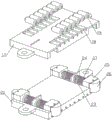
FIG. 1 is a schematic front view of the overall structure of the present invention;
FIG. 2 is a schematic view of the back of the overall structure of the present invention;
FIG. 3 is a structural diagram of the position relationship between the first support plate and the power mechanism;
FIG. 4 is an exploded view of the sliding assembly of the present invention;
FIG. 5 is a schematic view of an assembly structure of the sliding assembly of the present invention;
FIG. 6 is a schematic view of a power mechanism according to the present invention;
FIG. 7 is a schematic view of the engagement structure of the second driving wheel and the second driving wheel;
FIG. 8 is a schematic view of the fitting structure of the fixing frame, the lifting mechanism and the water tank;
FIG. 9 is a schematic structural view of the lifting mechanism;
FIG. 10 is a schematic view of the mating arrangement of the water tank and the switching mechanism;
FIG. 11 is a schematic view of the mating structure of the water tank and the rack;
FIG. 12 is a half sectional view of the water tank;
FIG. 13 is a schematic view of the construction of the connector;
FIG. 14 is a schematic view of the structure of the air jet device;
FIG. 15 is a schematic view of the mating structure of the water tank and the water nozzle;
fig. 16 is a schematic view of the matching structure of the rope and the guide wheel.
Detailed Description
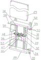
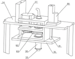
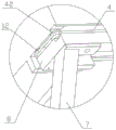
As shown in the figure, the semi-automatic solar photovoltaic panel scrubbing device comprises a plurality of first supporting plates 1 which are arranged in sequence, a first mounting plate 2 is mounted on the upper end face of each first supporting plate, and a photovoltaic panel 3 is mounted on the upper end face of each first mounting plate. The upper and lower both ends face of first mounting panel is equipped with horizontal extension's spout 4 respectively, install in the spout with spout sliding fit's sliding component 5, two sliding component link together through setting up mount 34 in the photovoltaic board top, install on the mount and carry out abluent washing subassembly 6 to the photovoltaic board, still include two second backup pads 7, install second mounting panel 8 in the second backup pad, between the adjacent first backup pad, be connected through first connecting plate 9 between adjacent first backup pad and the second backup pad, between the adjacent first mounting panel, be connected through second connecting plate 10 between adjacent first mounting panel and the second installation version. The cleaning device is characterized by further comprising a power mechanism 11 arranged below the first mounting plate, two ends of the sliding assembly are connected with the power mechanism through ropes, guide wheels 42 in transmission fit with the ropes 12 are arranged on the second mounting plate, a water control box 13 and an electric control box 14 are arranged on the bottom end face of the second mounting plate, the water control box is respectively connected with the cleaning assembly and a water supply source through a water pipe 15, and the electric control box is connected with the power mechanism, the cleaning assembly and a power supply through cables 16; the cleaning assembly comprises a movable frame 36 which is arranged on the top of a fixed frame through a lifting mechanism 35 and moves up and down, a second motor 37 is arranged on the movable frame, a rotating pipe 38 which extends downwards is further rotatably arranged on the movable frame, the second motor is in transmission fit with the rotating pipe through a transmission mechanism, a guide pipe 39 which is in plug-in fit with an inner cavity of the rotating pipe is fixedly arranged on the upper portion of the movable frame, the outer wall of the guide pipe is in rotation seal fit with the inner wall of the rotating pipe, the upper end of the guide pipe is connected with a water pipe, a water tank 40 which is communicated with the lower end of the guide pipe is fixedly arranged on the lower portion of the rotating pipe, an erasing device 62 which can be erased and matched with the photovoltaic panel and can be lifted up and down is arranged on the bottom of the water tank through a switching mechanism 61, a cleaning device 100 which is contacted with the surface of the photovoltaic panel is further arranged on the bottom of the water, also included is a connector 60 that electrically connects the heating box, switching mechanism, air injector, water injector, and electrical control box.
In this patent, first backup pad bottom plate part is fixed subaerial, and the quantity of first support frame has a plurality of, and each first support frame transversely arranges in proper order, can confirm specific quantity according to photovoltaic power plant's actual need capacity. The upper end of the supporting part of the first supporting frame is connected with a first mounting plate in an installing mode, and a photovoltaic panel is inserted into the first mounting plate. A photovoltaic device unit is formed by the single first supporting plate, the first mounting plate and the photovoltaic plate, and a photovoltaic device group is formed by the plurality of photovoltaic device units. The second supporting plate bottom plate is fixed on the ground, the second supporting plate and a second mounting plate arranged on the second supporting plate form a limiting device, and the limiting device is arranged at two ends of the photovoltaic device group. Between two first backup pads, be connected through first connecting plate between first backup pad and the second backup pad, through the second connecting plate between two first mounting panels, first mounting panel and the second mounting panel, strengthened photovoltaic device group overall stability. The upper end face and the lower end face of the first mounting plate are respectively provided with a sliding groove, and the sliding grooves are transversely arranged and are sequentially butted. Be equipped with the sliding component in the spout, the sliding component can be followed the spout and transversely freely slided.
In this patent, still including setting up the mount in the photovoltaic board top, the lower extreme of two support arms of mount is in the same place with two sliding component installations respectively. Thus, under the matching of the sliding assembly, the fixing frame can freely and transversely slide above the photovoltaic panel. Install the washing subassembly that sets up towards the photovoltaic board on the mount, the main effect of washing subassembly is that clean the photovoltaic board surface, cleans dust, leaf, bird's dung, ice and snow etc. that also fall to the photovoltaic board top.
This patent is still including installing the power unit in first mounting panel below, and the both ends and the power unit of slip subassembly pass through the rope and are connected, be equipped with on the second mounting panel with rope transmission complex leading wheel. Because the second mounting panel sets up the tip at the photovoltaic device group, the leading wheel that sets up on the second mounting panel mainly functions is for providing rotation support for the rope, and the drive circuit of rope does not provide the switching-over support. Thus, the power mechanism, the rope and the sliding component form a transmission loop. When the power mechanism acts, power is transmitted through the rope and the sliding assembly is driven to transversely slide along the sliding groove, namely the fixing frame is driven to transversely slide relative to the photovoltaic panel along the sliding groove. In this patent, install water control box and electric control box on the second mounting panel bottom face, wherein, water control box respectively with wash subassembly, water supply pipe connection, water control box's primary function is that control water supply pipe supplies water to wasing the subassembly, washs the subassembly like this and not only can clean the photovoltaic board, can also permeate with the water, wash stubborn foreign matter, guaranteed the cleaning performance. The electric control box is respectively connected with the power mechanism, the cleaning assembly and the power supply through cables, and the electric control box is mainly used for controlling the action of the power mechanism, namely controlling the movement and the cleaning action of the cleaning assembly on the fixing frame, so that automatic cleaning is realized.
In this patent, wash the subassembly and include and install the adjustable shelf at the fixed bolster top through elevating system, consequently go up and down through control elevating system, just can control reciprocating of adjustable shelf, also can realize installing reciprocating of each part on the adjustable shelf, realized also that this patent pastes tight photovoltaic board downwards and cleans and clean the photovoltaic board that leaves that finishes. In this patent, a movable frame is provided with various devices, mainly including a second motor, a rotary pipe, a flow guide pipe, a water tank, an erasing device, a cleaning device, a water spraying device, an air spraying device, a connector, and the like. Wherein the second motor is fixed mounting on the adjustable shelf, and the rotating pipe rotates and installs on the adjustable shelf, and the rotating pipe sets up towards photovoltaic board downwardly extending. In this patent, a transmission mechanism is installed between the second motor and the rotary pipe, and the second motor can drive the rotary pipe to rotate through the transmission mechanism. In this patent, the water tank is fixed mounting to the rotary pipe lower extreme, and aforementioned wiping arrangement, cleaning device, water jet equipment, air jet system all install on the water tank. Therefore, when the second motor is controlled to rotate, the second motor can drive the water tank to rotate through the rotating pipe, namely, the erasing device, the cleaning device, the water spraying device and the air spraying device on the water tank are driven to rotate on the surface of the photovoltaic panel. Because when elevating system descends, cleaning device just contacted photovoltaic board surface, consequently when rotatory, cleaning device can easily clean the foreign matter such as dust, leaf on photovoltaic board surface and sweep away, has guaranteed the cleanness of photovoltaic board. In this patent, because it installs on the water tank through switching mechanism to erase the device, and switching mechanism's main function is the drive again and erases the device and reciprocate, consequently when switching mechanism drive is erased the device and is pressed close to the photovoltaic board, it will be difficult to the foreign matter of cleaing away to photovoltaic board surface to erase the device, clears up the clearance like bird dung, ice, snow, has greatly shortened the influence time of ice and snow weather to photovoltaic power generation station, has improved the generating efficiency. In the patent, a flow guide pipe is fixedly arranged on the upper part of the movable frame and is in plug-in fit with an inner cavity of the rotating pipe. When the rotating pipe is lifted with the lifting mechanism, the guide pipe is axially matched with the inner wall of the rotating pipe in a sliding manner. When the second motor drives the rotating pipe to rotate, the inner wall of the rotating pipe is in sliding fit with the outer wall of the flow guide pipe. No matter the rotation fit or the axial sliding fit, the outer wall of the guide pipe and the inner wall of the rotating pipe are in sealing fit. The upper end of the flow guide pipe is connected with the water pipe, and the lower end of the flow guide pipe is communicated with the water tank, so that the water control box can control the water supply source to inject water into the water tank through the water pipe and the flow guide pipe. When the surface of the photovoltaic panel needs to be cleaned, the water tank can spray water to the photovoltaic panel through the water spraying device. Firstly, the cleaning agent has the functions of moistening dirt and softening the dirt (such as bird dung and ice and snow), and secondly, the cleaning agent has the function of washing the surface of the photovoltaic panel by water, so that the cleaning effect and efficiency are greatly improved. In this patent, the heating cabinet is installed in the water tank outside, install the jet system to photovoltaic board steam injection gas on the heating cabinet. In winter, when severe weather such as ice and snow is encountered, the common cleaning device is often unusable and can only be used after the weather is heated and then the photovoltaic power station is started. In this patent, the heating cabinet can provide continuous hot gas, and jet system can all spray on the ice and snow on photovoltaic board surface with these hot gases, and ice and snow can flow away automatically after melting into water. After the ice and snow are completely melted, the air injection device also has the function of drying the surface of the photovoltaic panel, so that not only can the melted ice and water be prevented from being condensed again, but also the function of drying the surface of the photovoltaic panel can be realized, and the photovoltaic panel can be preheated to reach the temperature and the state with the best photoelectric conversion efficiency as soon as possible. The electric heating device also comprises a wire connector, and the wire connector is mainly used for realizing the electric connection of the heating box, the switching mechanism, the air injection device, the water spraying device and the electric control box under the rotating condition of the rotating pipe.
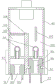
In this embodiment, the sliding assembly includes cartridge complex epitheca 17, inferior valve 20, the epitheca up end is equipped with first groove 18, install first gyro wheel 19 with epitheca normal running fit in the first inslot, the terminal surface is equipped with second groove 21 under the inferior valve, the second inslot is equipped with second gyro wheel 22, the inferior valve up end is equipped with third groove 23, the third inslot is equipped with baffle 24, the third inslot is installed with third groove sliding fit's fixed block 25, the fixed block inner chamber install with fixed block normal running fit's third gyro wheel 26, install first spring 27 between the lateral wall of fixed block and the baffle. The upper end surface of the sliding block component is provided with a first roller, the lower end surface of the sliding block component is provided with a second roller, the two side positions of the sliding block component are provided with third rollers which are matched with the sliding block component in a rotating way, when the sliding block component slides in the sliding groove, the first roller, the second roller and the third rollers roll along the inner wall of the sliding groove, the friction force borne by the sliding block in the sliding process is reduced, the smoothness of the sliding block component in the sliding process in the sliding groove is ensured, the fixed block and the third groove are matched in a sliding way and limited between the notch clamping block and the baffle plate, a first spring is arranged between the fixed block and the baffle plate, the first spring is a compression spring, the first spring pushes the fixed block to slide outwards, thus, the third rollers on the two sides of the sliding block component are tightly pressed on the side wall of the sliding groove, the sliding stability of the sliding block component in the sliding groove is improved, two sliding assembly that lie in lower extreme on the first mounting panel are connected through wasing the subassembly, in the cleaning process, need guarantee that two sliding assembly of lower extreme slide along the spout in step on the first mounting panel, thereby reach and stabilize abluent effect, sliding assembly is equipped with first gyro wheel respectively in the position with the spout contact, the second gyro wheel, the third gyro wheel, improve the gliding smoothness nature of sliding assembly through rolling friction, the third gyro wheel compresses tightly on the spout inner wall owing to the effect of first spring and the sliding assembly both sides that make, both guarantee the gliding smoothness nature of sliding assembly, the gliding stability of sliding assembly has been guaranteed again.
In this embodiment, the power mechanism includes a box 28 and a box cover 29 which are connected correspondingly, a first rotating shaft 30 and a second rotating shaft 31 which are vertically arranged in parallel are rotatably installed in the box, a motor fixing plate 32 is installed on the inner wall of the central part of the box between the first rotating shaft and the second rotating shaft, a first motor 33 is installed on the motor fixing plate, a driving gear 47 is installed on the output shaft of the first motor, a left gear 48 engaged with the driving gear at the left side is installed on the first rotating shaft, a right gear 49 engaged with the driving gear at the right side is installed on the second rotating shaft, the rope includes an upper rope 53 and a lower rope 54 which are respectively connected with two sliding assemblies, the upper rope and the lower rope both include a left rope section 50 wound and a right rope section 51 wound and engaged with the second rotating shaft at the forward direction, the outer ends of the left rope section and the right rope section far away from the first motor are respectively connected with a straight rope section 58 of the same rope through an upper port, the inner ends of the left rope section and the right rope section of the same rope far away from the upper port 52 and the lower port 55 are connected together through an inner rope section 56, and the rope device also comprises an inner pulley 57 which is arranged in the box body and is in transmission fit with the inner rope section, and an outer pulley 59 which is close to the upper port and the lower port and is in limit transmission fit with the straight rope section. In this patent, power unit mainly includes the first pivot, the second pivot, each segmentation of first motor and rope of setting in the box body. Wherein, first pivot and second pivot are vertical rotation and install in the box body, and both are parallel arrangement relation. The first motor is arranged on a motor fixing plate on the inner wall of the central part of the box body between the first rotating shaft and the second rotating shaft, and the first motor is mainly used for providing power for the power mechanism. The output shaft of the first motor is provided with a driving gear, the first rotating shaft is provided with a left gear which is meshed with the driving gear on the left, and the second rotating shaft is provided with a right gear which is meshed with the driving gear on the right. Therefore, when the first motor rotates, the first motor drives the first rotating shaft and the second rotating shaft to rotate synchronously through the left gear and the right gear. The rope in the box body is mainly two, one rope is an upper rope connected with the upper sliding component, and the other rope is a lower rope connected with the lower sliding component. The upper rope and the lower rope both comprise three rope sections: a left rope segment, a right rope segment, and an inner rope segment. Wherein, left rope section and first pivot forward winding cooperation, right rope section and the cooperation of second pivot reverse winding. For convenience of description, one end of the left rope segment and the right rope segment away from the first motor is called an outer end, and the other end is called an inner end. The box body is provided with an upper port and a lower port which correspond to the outer ends of the left rope section and the right rope section, and the outer ends of the left rope section and the right rope section are respectively connected with the straight rope section of the same rope through the upper port and the lower port, so that the connection with the sliding assembly is realized. The inner ends of the left rope segment and the right rope segment of the same rope are connected together through the inner rope segments, so that all the rope segments of the rope form a complete loop. In this patent, still install in the box body with interior rope section transmission complex inboard pulley and be close to last port and lower port and with the spacing transmission complex outside pulley of straight rope section. The main effect of above-mentioned two pulleys is that the interval with straight rope portion and inner rope portion is pulled open as far as possible, just so can twine more left rope portions and right rope portion in first pivot and second pivot, and left rope portion and right rope portion are longer more, and left rope portion and right rope portion just are big more with the frictional force of first pivot and second pivot, and power transmission is just more reliable. The outside pulley has the second effect, be exactly with straight rope section restriction in last port and lower port, fundamentally has avoided along with the rotation of first motor, straight rope section slope to box body center gradually and lead to with the friction of last port and lower port, has greatly improved the reliability of this patent.
In this embodiment, the lifting mechanism includes two first solenoid valves 80 vertically installed on the fixed frame at intervals, and the first valve rods 81 of the two solenoid valves are respectively and fixedly connected with two ends of the movable frame. The operation of the first electromagnetic valve is controlled by the electric control box. When dirt or ice and snow which are difficult to remove on the surface of the photovoltaic panel are cleaned by the wiping device, the first electromagnetic valve is controlled to act, the movable frame is made to descend, and therefore the wiping device is close to the photovoltaic panel. And when the erasing is finished or the strong erasing is not needed, the first electromagnetic valve and the movable frame are controlled to reset.
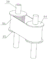
In this embodiment, the transmission mechanism includes a second driving gear 82 installed at the output end of the second motor, a second transmission gear 83 engaged with the second driving gear is fixedly installed on the rotating tube, or includes a second driving wheel 84 installed at the output end of the second motor, a second transmission wheel 85 is fixedly installed on the rotating tube, and a transmission belt 86 is sleeved on the second driving wheel and the second transmission wheel.
In this embodiment, the switching mechanism includes a carriage 87 slidably mounted on the water tank up and down, a first engaging slot 90 extending transversely is provided on the carriage, the erasing device is engaged in the first engaging slot under the carriage, and a second electromagnetic valve 88 vertically mounted on the upper portion of the water tank, and a second valve rod 89 of the second electromagnetic valve is fixedly connected to the carriage. In the switching device, the sliding frame and the second electromagnetic valve are core structures, wherein the sliding frame surrounds the periphery of the lower part of the water tank and is in up-and-down sliding fit with the lower part of the water tank. And the second solenoid valve is fixedly arranged at the upper part of the water tank, and a second valve rod of the second solenoid valve extends downwards and is fixedly connected with the sliding frame. Thus, when the second solenoid valve is actuated, the second solenoid valve will push the carriage up and down along the tank. In this patent, be equipped with the first draw-in groove of horizontal extension on the balladeur train, wipe the device and block in the first draw-in groove of balladeur train below, consequently can install or dismantle and wipe the device through first draw-in groove, it is very convenient when needs are changed.
In this embodiment, the erasing device includes a first clamping frame 91 laterally clamped and matched with the switching mechanism, a first water channel 92 penetrating up and down is disposed in the middle of the clamping frame and corresponding to the water spraying device, and a row of shorter bristles 93 is respectively fixed on two sides of the clamping frame. In this erasing device, first card frame is the main structure body who erases the device, and the first water course in its middle part corresponds the setting with water jet equipment, and the primary function makes things convenient for water jet equipment to spray water through first water course, erases the device like this and can soak, moisten the foreign matter when erasing the foreign matter, helps cleaing away fast of foreign matter, can also be used for wasing the photovoltaic board. In the erasing device, the first clamping frame is provided with the bristles which are hard in texture and mainly suitable for erasing intractable stains and ice and snow which are difficult to erase.
In this embodiment, the cleaning device includes a second slot 94 transversely disposed at the bottom of the water tank, a second clamping frame 95 is slidably clamped in the second slot, a second water channel 96 which is vertically through and corresponds to the water spraying device is disposed in the middle of the second clamping frame, and a row of longer bristles 97 is fixedly disposed on two sides of the second clamping frame respectively. In the cleaning device, the second clamping frame is a structural main body of the cleaning device, and the second clamping frame is arranged on the water tank through a second clamping groove at the bottom of the water tank. The second water course in its middle part corresponds the setting with water jet equipment, and the primary function makes things convenient for water jet equipment to pass through the second water course water spray, and cleaning device can wash the photovoltaic board when sweeping foreign matters such as dust, leaf like this, and is cleaner. In the cleaning device, the second clamping frame is provided with soft fur which has soft texture and is mainly suitable for cleaning foreign matters with light weight, such as dust, leaves and the like. In addition, in this patent, the soft hair sets up to be longer than the bristle, and in natural state, the soft hair just touches the photovoltaic board, and the bristle is far away from the photovoltaic board, cleans all at ordinary times with the soft hair.
In this embodiment, the water spraying device includes a water pump 98 installed in the water tank, the outlet of the water pump extends out of the bottom surface of the water tank through a plurality of nozzles 99, and the end of each nozzle is fixedly provided with a water nozzle 101. After the water pump is installed in the water tank, the water pump passes through the spray pipe and the clear water sprayed out from the water spray nozzle, the speed is high, the impact force is large, the effect of washing foreign matters or dirt is achieved, and the cleaning efficiency and the cleaning effect are improved.
In this embodiment, the water tank internal stability is equipped with the baffle 104 that is divided into the left chamber 102 that corresponds with the fluff respectively and the right chamber 103 that corresponds with the bristle with water tank inner chamber lower part, left chamber upper mouth portion transversely articulates there is the left valve plate 105 that can block up left chamber, right chamber upper mouth portion transversely articulates there is the right valve plate 106 that can block up right chamber, be equipped with respectively on the water tank outer wall of second valve stem both sides with left valve plate and right valve plate coaxial rigid coupling's left side gear 107 and right side gear 108, the vertical rack 109 that sets firmly with left side gear and right side gear engagement on the second valve stem. In this patent, after the baffle cut apart the water tank into two cavities, just be equivalent to there are two sets of water supply system, and two sets of water supply system carry out on-off control through the left valve plate and the right valve plate of upper port portion respectively. Because left valve plate and right valve plate coaxial coupling have left side gear and right side gear respectively, and the vertical rack that sets firmly with left side gear and right side gear engagement on the second valve rod again, consequently, when stubborn dirt or foreign matter need be erased, switching mechanism promotes the balladeur train downwards, and the photovoltaic board is pressed close to the bristle, and the rack also promotes left side gear and right side gear synchronous revolution simultaneously. At the moment, the right valve plate at the upper part of the right cavity corresponding to the erasing device is opened, the left valve plate is closed, and water in the water tank is sprayed out only through the first water channel by the water pump, namely the auxiliary bristles are used for forcibly erasing. When no stubborn dirt exists, the switching mechanism pushes the sliding frame to reset upwards, the bristles are far away from the photovoltaic panel, the right valve plate is closed, the left valve plate is opened, the water pump sprays water to the second water channel where the bristles are located through the left cavity at the moment, and the bristles are assisted to clean dust or leaves. When neither cleaning nor wiping is needed, the water pump and the water supply source are both closed, and water is not sprayed outwards.
In this embodiment, the wire connector includes a plurality of pipes constituting the rotating pipe, the pipes include an inner metal pipe 65, a switching insulating pipe 66, a switching metal pipe 67, a heating insulating pipe 68, a heating metal pipe 69, a water spraying insulating pipe 70, a water spraying metal pipe 71, a gas spraying insulating pipe 72 and a gas spraying metal pipe 73 which are coaxially and fixedly sleeved together from inside to outside, in any two adjacent pipes, the end of the pipe opposite to the inner pipe extends out of a section of an extending section 79 of the end of the pipe opposite to the outer pipe, and the movable frame and the water tank are respectively provided with a wiring device 74 which electrically connects the cables of the heating box, the switching mechanism, the gas spraying device and the water spraying device to the metal pipes; the wiring device comprises a protective shell 75, a connecting platform 76 can be fixedly arranged on the protective shell, five metal elastic sheets 77 are arranged on the connecting platform at intervals, a wiring terminal 78 electrically connected with a power supply anode of the heating box, a power supply anode of the switching mechanism, a power supply anode of the air injection device, a power supply anode of the water injection device and a power supply cathode is fixedly arranged at one end of each metal elastic sheet, and the other ends of the metal elastic sheets of the upper wiring device and the lower wiring device are correspondingly and elastically pressed on the extending sections of the metal pipes. In this patent, the wire connector mainly includes a plurality of pipes that constitute the rotating pipe, that is to say from inside to outside coaxial fixed suit in proper order in the inner metal pipe together, switch insulating tube, switch metal pipe, heating insulating tube, heating metal pipe, water spray insulating tube, water spray metal pipe, jet-propelled insulating tube and jet-propelled metal pipe. Any adjacent tubes are not in electrical connection, so each metal tube is a conductive wire, and five conductive wires are in total. In any two adjacent pipes, the end part of the pipe opposite to the inner pipe extends out of an extension section of the end part of the pipe opposite to the outer pipe, and the extension section is mainly used for facilitating the connection of the metal elastic sheets. The movable frame and the water tank are respectively provided with a wiring device which electrically connects the cables of the heating box, the switching mechanism, the air injection device and the water injection device to the metal pipes correspondingly. The wiring device comprises a protective shell, a connecting table can be fixedly arranged on the protective shell, and five metal elastic sheets are arranged on the connecting table at intervals. The five metal elastic sheets are respectively and elastically pressed on the extension sections of the inner metal pipe, the switching metal pipe, the heating metal pipe, the water spraying metal pipe and the air spraying metal pipe. Because the elastic pressing relationship is adopted, the electric connection relationship between the rotating pipe and the rotating pipe is not influenced even if the rotating pipe rotates, and the working reliability of the rotary pipe is ensured. One end of the last four metal elastic sheets is fixedly provided with a binding post which is respectively connected with the power supply anode of the heating box, the power supply anode of the switching mechanism, the power supply anode of the air injection device and the power supply anode of the water injection device, and one end of the first metal elastic sheet is fixedly provided with a binding post which is electrically connected with the power supply cathode.
As shown in fig. 14, the air-jet device 63 includes a heating box 41 in which a heating wire is installed for heating air in the heating box. The upper portion of the heating box is provided with an air inlet, a fan is installed in the air inlet, the fan can suck external air into the heating box to supplement air for the heating box, and the fan is one of functions of the fan. The heating cabinet bottom is equipped with a heating hole, and the heating hole sets up towards the photovoltaic board. And the second function of the fan is to pressurize hot air in the heating box and then spray the hot air out of the heating hole to the photovoltaic panel, so that the melting and drying of ice and snow on the photovoltaic panel are realized.
Claims (1)
1. A semi-automatic solar photovoltaic panel scrubbing device is characterized in that: the photovoltaic panel cleaning device comprises a plurality of first supporting plates (1) which are sequentially arranged, wherein a first mounting plate (2) is installed on the upper end face of each first supporting plate (1), a photovoltaic panel (3) is installed on the upper end face of each first mounting plate (2), transversely extending sliding grooves (4) are respectively formed in the upper end face and the lower end face of each first mounting plate (2), sliding assemblies (5) which are in sliding fit with the sliding grooves (4) are installed in the sliding grooves (4), the two sliding assemblies (5) are connected together through a fixing frame (34) which is arranged above the photovoltaic panel, cleaning assemblies (6) which clean the photovoltaic panel are installed on the fixing frame, two second supporting plates (7) are further included, second mounting plates (8) are installed on the second supporting plates (7), adjacent first supporting plates (1) are connected with one another through first connecting plates (9), and adjacent first mounting plates (2) are connected with one another through first connecting plates (9), The adjacent first mounting plate (2) is connected with the second mounting plate through a second connecting plate (10), the power mechanism (11) is mounted below the first mounting plate (2), two ends of the sliding assembly (5) are connected with the power mechanism (11) through ropes (12), a guide wheel (42) in transmission fit with the ropes (12) is arranged on the second mounting plate (8), a water control box (13) and an electric control box (14) are mounted on the bottom end face of the second mounting plate (8), the water control box (13) is respectively connected with the cleaning assembly (6) and a water supply source through a water pipe (15), and the electric control box (14) is connected with the power mechanism (11), the cleaning assembly (6) and the power supply through cables (16); the cleaning assembly (6) comprises a movable frame (36) which is arranged at the top of a fixed frame (34) through a lifting mechanism (35) and moves up and down, a second motor (37) is arranged on the movable frame, a rotating pipe (38) which extends downwards is further rotatably arranged on the movable frame, the second motor (37) is in transmission fit with the rotating pipe (38) through a transmission mechanism (3-9), a guide pipe (39) which is in plug-in fit with the inner cavity of the rotating pipe is fixedly arranged at the upper part of the movable frame, the outer wall of the guide pipe is in rotating seal fit with the inner wall of the rotating pipe, the upper end of the guide pipe is connected with a water pipe (15), a water tank (40) which is communicated with the lower end of the guide pipe is fixedly arranged at the lower part of the rotating pipe (38), an erasing device (62) which can be in scrubbing fit with the photovoltaic panel (3) and can be lifted up and down is arranged at the bottom of, the photovoltaic panel cleaning device is characterized in that a heating box (41) is installed on the outer side of the water tank, an air injection device (63) for injecting hot air to the photovoltaic panel (3) is installed on the heating box (41), a water injection device (64) for injecting water to the photovoltaic panel (3) through an erasing device (62) or a cleaning device (100) is installed on the water tank (40), and the photovoltaic panel cleaning device further comprises a wire connector (60) for electrically connecting the heating box (41), a switching mechanism (61), the air injection device (63), the water injection device (64) and the electric control box (14); the lifting mechanism (35) comprises two first electromagnetic valves (80) vertically arranged on the fixed frame (34) at intervals, and first valve rods (81) of the two electromagnetic valves (80) are respectively and fixedly connected with two ends of the movable frame (36); the sliding assembly (5) comprises an upper shell (17) and a lower shell (20) which are matched in an inserted manner, a first groove (18) is formed in the upper end face of the upper shell (17), a first roller (19) which is matched with the upper shell (17) in a rotating manner is installed in the first groove (18), a second groove (21) is formed in the lower end face of the lower shell (20), a second roller (22) is arranged in the second groove (21), a third groove (23) is formed in the upper end face of the lower shell (20), a baffle plate (24) is arranged in the third groove (23), a fixing block (25) which is matched with the third groove (23) in a sliding manner is installed in the third groove (23), a third roller (26) which is matched with the fixing block (25) in a rotating manner is installed in the inner cavity of the fixing block (25), and a first spring (27) is installed between; power unit (11) is including corresponding box body (28) of connecting, lid (29), first pivot (30) and second pivot (31) of parallel vertical setting are installed to box body (28) internal rotation, install motor fixed plate (32) on box body (28) central part inner wall between first pivot (30) and second pivot (31), install first motor (33) on motor fixed plate (32), install drive gear (47) on the output shaft of first motor (33), install left gear (48) with the left meshing of drive gear on first pivot (30), install right gear (49) with the right meshing of drive gear on second pivot (31), rope (12) are including last rope (53) and lower rope (54) be connected with two slip subassemblies (5) respectively, go up rope (53) and lower rope (54) all include with first pivot forward winding complex left rope section (50) and with the reverse winding complex right rope section (51) of second pivot The outer end of the left rope section (50) and the outer end of the right rope section (51) far away from the first motor are respectively connected with a straight rope section (58) of the same rope through an upper port (52) and a lower port 55 which are arranged on two sides of the box body, the inner ends of the left rope section (50) and the right rope section (51) far away from the upper port and the lower port of the same rope are connected together through an inner rope section (56), and the rope device further comprises an inner side pulley (57) which is installed in the box body and is in transmission fit with the inner rope section, and an outer side pulley (59) which is close to the upper port and the lower port and is in transmission fit with the.
Priority Applications (1)
| Application Number | Priority Date | Filing Date | Title |
|---|---|---|---|
| CN201611009135.XA CN108075721B (en) | 2016-11-16 | 2016-11-16 | Semi-automatic solar photovoltaic panel scrubbing device |
Applications Claiming Priority (1)
| Application Number | Priority Date | Filing Date | Title |
|---|---|---|---|
| CN201611009135.XA CN108075721B (en) | 2016-11-16 | 2016-11-16 | Semi-automatic solar photovoltaic panel scrubbing device |
Publications (2)
| Publication Number | Publication Date |
|---|---|
| CN108075721A CN108075721A (en) | 2018-05-25 |
| CN108075721B true CN108075721B (en) | 2020-06-23 |
Family
ID=62163423
Family Applications (1)
| Application Number | Title | Priority Date | Filing Date |
|---|---|---|---|
| CN201611009135.XA Active CN108075721B (en) | 2016-11-16 | 2016-11-16 | Semi-automatic solar photovoltaic panel scrubbing device |
Country Status (1)
| Country | Link |
|---|---|
| CN (1) | CN108075721B (en) |
Families Citing this family (2)
| Publication number | Priority date | Publication date | Assignee | Title |
|---|---|---|---|---|
| CN110729961B (en) * | 2019-11-25 | 2021-07-02 | 郑州航空工业管理学院 | Solar power generation instrument based on low-dimensional photoelectric material |
| CN114384200B (en) * | 2020-10-02 | 2024-01-05 | 三捷环境工程咨询(杭州)有限公司 | Environment detection equipment capable of rapidly detecting air quality |
Citations (1)
| Publication number | Priority date | Publication date | Assignee | Title |
|---|---|---|---|---|
| CN202231046U (en) * | 2011-08-28 | 2012-05-23 | 大连中隆新能源科技有限公司 | Liquid spray type automatic solar battery panel cleaning device |
-
2016
- 2016-11-16 CN CN201611009135.XA patent/CN108075721B/en active Active
Patent Citations (1)
| Publication number | Priority date | Publication date | Assignee | Title |
|---|---|---|---|---|
| CN202231046U (en) * | 2011-08-28 | 2012-05-23 | 大连中隆新能源科技有限公司 | Liquid spray type automatic solar battery panel cleaning device |
Also Published As
| Publication number | Publication date |
|---|---|
| CN108075721A (en) | 2018-05-25 |
Similar Documents
| Publication | Publication Date | Title |
|---|---|---|
| KR101837176B1 (en) | Robot apparatus for cleaning solar cell panel | |
| TW201624911A (en) | Cleaning device of solar power generation panel | |
| CN110022124B (en) | Cleaning device for solar photovoltaic panel | |
| CN108075721B (en) | Semi-automatic solar photovoltaic panel scrubbing device | |
| CN108075724B (en) | Special photoelectric equipment cleaning tool for electric power system | |
| CN115037241A (en) | Automatic cleaning system for photovoltaic module | |
| CN108075715A (en) | Unattended formula high-efficiency photovoltaic electrification station | |
| CN108768281A (en) | A kind of photovoltaic generating system with self-cleaning function | |
| CN115864946A (en) | Photovoltaic power station cleaning robot, system and working method thereof | |
| CN215142684U (en) | Moving platform of photo-thermal plate cleaning equipment | |
| CN108988771A (en) | A kind of solar panel cleaning equipment | |
| CN216790550U (en) | Balcony wall-mounted flat plate solar automatic cleaning device | |
| CN205413855U (en) | Frame -type photovoltaic cleans machine people | |
| CN111842236A (en) | Photovoltaic board cleaning device | |
| CN219655930U (en) | Solar street lamp capable of automatically cleaning solar panel | |
| CN108075719A (en) | With the high solar energy photovoltaic system auxiliary tool of efficiency of erasing | |
| CN207325536U (en) | A kind of solar panel cleaning device | |
| CN208513150U (en) | A kind of solar photovoltaic assembly surface cleaning apparatus | |
| CN108075716A (en) | Multifunction power photovoltaic power generation apparatus | |
| CN108075723A (en) | Photo-voltaic power generation station special maintenance equipment | |
| CN108075720A (en) | Electric power photovoltaic panel winter service device | |
| CN109877074B (en) | Cleaning device for passive photovoltaic module | |
| CN219164512U (en) | Marine floating type photovoltaic power station assembly cleaning system | |
| CN219918848U (en) | Photovoltaic module belt cleaning device | |
| CN219204450U (en) | Photovoltaic board cleaning equipment |
Legal Events
| Date | Code | Title | Description |
|---|---|---|---|
| PB01 | Publication | ||
| PB01 | Publication | ||
| SE01 | Entry into force of request for substantive examination | ||
| SE01 | Entry into force of request for substantive examination | ||
| TA01 | Transfer of patent application right |
Effective date of registration: 20190411 Address after: 261021 No. 425 Dongfeng West Street, Weicheng District, Weifang City, Shandong Province Applicant after: State Grid Shandong Electric Power Company Weifang Power Supply Company Applicant after: State Grid Corporation of China Address before: 261041 No. 8221 Dongfeng East Street, Weifang City, Shandong Province Applicant before: Liu Weihua |
|
| TA01 | Transfer of patent application right | ||
| GR01 | Patent grant | ||
| GR01 | Patent grant |