CN107196770B - System for supplying power through signal wire - Google Patents
System for supplying power through signal wire Download PDFInfo
- Publication number
- CN107196770B CN107196770B CN201710630537.XA CN201710630537A CN107196770B CN 107196770 B CN107196770 B CN 107196770B CN 201710630537 A CN201710630537 A CN 201710630537A CN 107196770 B CN107196770 B CN 107196770B
- Authority
- CN
- China
- Prior art keywords
- power supply
- module
- communication
- resistor
- output
- Prior art date
- Legal status (The legal status is an assumption and is not a legal conclusion. Google has not performed a legal analysis and makes no representation as to the accuracy of the status listed.)
- Active
Links
Images


Classifications
-
- H—ELECTRICITY
- H04—ELECTRIC COMMUNICATION TECHNIQUE
- H04L—TRANSMISSION OF DIGITAL INFORMATION, e.g. TELEGRAPHIC COMMUNICATION
- H04L12/00—Data switching networks
- H04L12/02—Details
- H04L12/10—Current supply arrangements
Abstract
The invention provides a system for supplying power through a signal wire, which comprises a main unit and at least one slave unit, wherein the main unit is connected with each slave unit through a ground wire GND and a communication signal wire SP. The main unit comprises a power supply module, a power supply monitoring module and a main communication module. The power supply monitoring module monitors the current value and the voltage value of the communication signal line output by the power supply module and feeds back the data information of the current value and the voltage value to the power supply module. Each slave unit at least comprises a unidirectional conduction module and a slave communication module; the master communication module is connected with the slave communication module through a communication signal line; the output end of the power supply module is connected to the communication signal wire, one end of the one-way conduction module is connected to the communication signal wire, and the other end of the one-way conduction module is connected to the ground wire; and the power supply module supplies power to the slave unit according to the signal feedback of the power supply control module according to the existence of the communication signal line.
Description
Technical Field
The present invention relates to the field of communications, and in particular, to a system for supplying power through a signal line.
Background
The main implementation methods for supplying power to the equipment or the external communication lines of the equipment by internal parts of the equipment mainly comprise the following points.
One method is to modify the existing communication interface and add a new circuit on the standard interface, thereby implementing external power supply. For example, a rectifying circuit, an input filtering circuit, a voltage regulating circuit and an output filtering circuit are added outside a standard RS485 bus system, so that power supply to the terminal node through 2 communication lines of RS485 is realized.
The other method and system for supplying power to the external equipment through the Ethernet are characterized in that a power supply unit, a port equipment detection unit and a mode switching unit are added, and an Ethernet idle line or a signal line is used as a power line to supply power to the external equipment. This method has a disadvantage in that a large number of signal lines are required between the information transmitting apparatus and the information receiving apparatus, and complicated circuit units are required for the receiving side and the transmitting side.
And the existing power supply mode is modified, and different voltages represent different codes by changing the voltage on the power line, so that communication between different equipment or different components in the equipment is realized. The method usually has the defect that only one-way communication can be realized, or more input/output ports on the host side are occupied; or the program design is complex, the output end needs to use an input/output port for analog sampling, the voltage on the communication line is monitored, and the power supply is increased when the voltage is reduced to be close to the lower limit of the equipment operation; meanwhile, the receiving end of the receiving device needs to distinguish different voltages to judge the communication information.
Disclosure of Invention
An object of an embodiment of the present invention is to provide a system that occupies fewer input/output ports of a device and is simple in structure to supply power through a signal line.
The invention provides a system for supplying power through a signal line, which comprises a main unit and at least one slave unit; the master unit is connected with the slave units through communication signal lines, the master unit at least comprises a power supply module, a power supply monitoring module and a master communication module, and any one of the slave units at least comprises a one-way conduction module and a slave communication module; the power supply module is connected with an input power supply, the control end of the power supply module is connected with the output end of the power supply monitoring module, one end of the communication signal wire is connected with the output end of the power supply module and the input/output port of the main communication module, the other end of the communication signal wire is connected with the input/output port of the slave communication module and one end of the one-way conduction module, and the input end of the power supply monitoring module is connected with the output end of the power supply module and the communication signal wire; the power supply module converts the accessed input power supply and outputs the converted output power supply through a communication signal line; the power supply monitoring module monitors a current value and a voltage value output by the power supply module through the communication signal line, and sends a control signal to the power supply module through an output end according to the current value and the voltage value, and the power supply module controls the converted output power supply according to the control signal; the master communication module and the slave communication module receive and transmit communication information through the communication signal line.
Further, when there is no communication between the master unit and the slave unit, the input and output ports of the master communication module and the slave communication module are both in an input mode, and the power supply module supplies power to the slave unit through a communication signal line and a unidirectional conducting module.
Further, when there is communication between the master unit and the slave unit, and the slave units communicate with each other, the input/output port of the communication module of the master unit or the slave unit, which initiates the communication, is in the output mode, and the input/output port of the communication module of the master unit or the slave unit, which receives the communication signal, is in the input mode; when a low level is transmitted on a communication signal line, the power supply monitoring module sends a control signal to the power supply module after monitoring that the current of the output power supply reaches a limit value, and the power supply module closes the output power supply or limits the output current after receiving the control signal; when a high level is transmitted on a communication signal line, the power supply monitoring module sends a control signal to the power supply module after monitoring a current value and a voltage value output by the power supply module, and the power supply module restores a normal power supply mode according to the control signal and supplies power through the communication signal line.
Further, the communication rates of the master communication module and the slave communication module are the same.
Furthermore, the power supply monitoring module comprises a current sampling amplifying circuit, wherein the current sampling amplifying circuit comprises a sampling resistor, a first resistor, a second resistor, a third resistor, a fourth resistor and a first amplifier; one end of the sampling resistor and one end of the first resistor are connected to the output end of the power supply module, and the other end of the sampling resistor and one end of the second resistor are connected to the communication signal line; the positive phase input end of the first amplifier is connected with the other end of the first resistor and one end of the third resistor, and the other end of the third resistor is grounded; the inverting input end of the first amplifier is connected with the other end of the second resistor and one end of a fourth resistor; the fourth resistor is connected in parallel between the output end and the inverting input end of the first amplifier.
Furthermore, the power supply monitoring module further comprises a comparison control circuit, which comprises a first comparator, a second comparator and an and-gate circuit, wherein one input end of the first comparator is connected with the output end of the first amplifier, the other input end of the first comparator is connected with a voltage corresponding to a preset current limit value, one input end of the second comparator is connected with the voltage on the communication signal line, the other input end of the second comparator is connected with a preset voltage, two input ends of the and-gate circuit are respectively connected with the output end of the first comparator and the output end of the second comparator, and the output end of the and-gate circuit is connected with the control end of the power supply module to output the control signal.
Further, power module includes interconnect stabiliser and relay, the input of stabiliser inserts input power, the input of relay is connected with the output of stabiliser, the control end inserts control signal, the output of relay does power module's output, the relay basis control signal control is exported to the power on the communication signal line has or not.
Further, the unidirectional conducting module comprises a diode, and the high-level voltage input to the slave unit by the communication signal line is less than or equal to the maximum voltage value allowed to be input by the slave unit port.
Furthermore, the unidirectional conduction module comprises a fifth resistor, a sixth resistor, a seventh resistor, a PMOS transistor and a triode, wherein the D pole of the PMOS transistor and one end of the fifth resistor are connected with the communication signal line, the other end of the fifth resistor and one end of the sixth resistor are connected with the base electrode of the triode, and the other end of the sixth resistor and the emitter electrode of the triode are grounded; and the G pole of the PMOS tube and the collector electrode of the triode are connected with one end of a seventh resistor, and the S pole of the PMOS tube and the other end of the seventh resistor are connected and used as the output end of the unidirectional conduction module.
Furthermore, the slave unit further comprises an energy storage module, one end of the energy storage module is connected to the output end of the unidirectional conduction module, the other end of the energy storage module is grounded, and when the voltage on the communication signal line is low voltage and cannot supply power to the slave unit, the energy storage unit supplies power to the slave unit.
The present technical solution also provides a method for supplying power through a signal line, which is used for supplying power between a master unit and at least one slave unit, and includes the steps of: converting an input power supply into an operating voltage required by a slave unit through the main unit processing;
supplying power to the slave unit through a communication signal line when there is no communication between the master unit and the slave unit; and according to the existence of the communication signal line, the power supply module supplies power to the slave unit according to the feedback signal of the power supply control module.
Further, the communication signal line adopts a standard logic level for signal transmission.
Further, when there is no communication between the master unit and the slave unit, power is supplied through the communication signal line.
Further, when the master unit and the slave units communicate with each other, a port of a communication module initiated by communication is set to be in an output mode, when a logic 0 level is transmitted on a communication signal line, the port of the communication initiation unit outputs a low level, after monitoring that the current output by the power supply reaches a limit value, a set control signal is given, and the power supply is output or the output current is limited according to the control signal; when the communication signal line transmits a logic high level, a port of a master unit or a slave unit initiated by communication outputs the high level, the power supply monitoring module monitors a current voltage value output by the power supply module and feeds the current voltage value back to the power supply module, and the power supply module supplies power through the communication signal line.
The system for supplying power through the signal wire has the following beneficial effects: the above-described system for supplying power via a signal line realizes a communication function between the master unit and the slave unit or between the slave units via a communication signal line.
The master unit supplies power to the slave unit through communication signals and has a protection function.
The slave unit gets electricity from the signal wire through the one-way conduction component, and the slave unit is provided with an energy storage part, so that the normal operation of the slave unit can be ensured when the signal wire does not provide power supply in the signal transmission process.
Drawings
In order to more clearly illustrate the technical solution of the present technical solution, the drawings needed to be used in the embodiments will be briefly introduced below, and it is obvious that the drawings in the following description are only some embodiments of the present invention, and it is obvious for those skilled in the art to obtain other drawings based on these drawings without creative efforts.
Fig. 1 is a block diagram of a system for supplying power through a signal line according to an embodiment of the present invention;
fig. 2 is a block diagram of a system for supplying power through a signal line according to an embodiment of the present invention, including two slave units;
fig. 3 is a current sampling amplifying circuit diagram of a power supply monitoring module of a system for supplying power through a signal line according to an embodiment of the present invention;
fig. 4 is a current-voltage comparison control circuit of a power supply monitoring module of a power supply system via a signal line according to an embodiment of the present invention;
fig. 5 is a circuit diagram of a power supply module of a system for supplying power through a signal line according to an embodiment of the present invention;
fig. 6 is a circuit diagram of a unidirectional conducting module of a system for supplying power through a signal line, which is implemented by a PMOS transistor according to an embodiment of the present invention.
Detailed Description
The technical solutions in the embodiments of the present invention will be clearly and completely described below with reference to the drawings in the embodiments of the present invention, and it is obvious that the described embodiments are only some embodiments, not all embodiments, of the present invention. All other embodiments obtained by a person skilled in the art based on the embodiments in the present technical solution without creative efforts shall fall within the protection scope of the present invention.
Referring to fig. 1 in conjunction with fig. 2, fig. 1 is a block diagram of a power supply system via signal lines, which includes a host unit and a slave unit. Fig. 2 is a block diagram of the system for supplying power through signal lines, which includes a master unit and two slave units. In other embodiments, three or more slave units may be included.
The technical scheme provides a system device for supplying power through a signal wire, which comprises a main unit 100 and at least one slave unit 200, wherein the main unit 100 is connected with each slave unit 200 through a ground wire GND and a communication signal wire SP.
The SP signal is signaled using standard logic levels (e.g., CMOS levels, TT L levels, etc.), so that no other dedicated signal processing circuitry is required for the entire system.
A master unit 100 and at least one slave unit 200; the master unit 100 and the slave unit 200 are connected by a communication signal line SP, and the master unit 100 at least includes a power supply module 101, a power supply monitoring module 102, and a master communication module 103. Any one of the slave units 200 includes at least a unidirectional conducting module 204 and a slave communication module 202.
The power supply module 101 is connected to an input power supply, a control end of the power supply module 101 is connected to an output end of the power supply monitoring module, one end of a communication signal line is connected to an output end of the power supply module 101 and an input/output port a _ RX/TX of the master communication module 103, the other end of the communication signal line is connected to an input/output port of the slave communication module 202 and one end of the unidirectional conducting module 204, and an input end of the power supply monitoring module 102 is connected to an output end of the power supply module 101 and the communication signal line SP.
The power supply module 101 converts the input power and outputs the converted output power through the communication signal line SP. The power supply monitoring module 102 monitors a current value and a voltage value output by the power supply module 101 through the communication signal line SP, and sends a control signal SW to the power supply module 101 through an output end according to the current value and the voltage value, and the power supply module 101 controls the converted output power supply according to the control signal SW.
The master communication module 103 and the slave communication module 202 receive and transmit communication information through the communication signal line SP.
The function of the unidirectional conducting block 204 is to unidirectionally feed power on the SP signal line to the network of power supplies VCC1 of the slave unit 200, while preventing the network of power supplies VCC1 of the slave unit 200 from discharging through the SP signal line when the SP signal line is low voltage.
Preferably, the communication rates of the master communication module 103 and the slave communication module 202 are the same.
When there is no communication between the master unit 100 and the slave unit 200, the digital signal ports of the master communication module 103 and the slave communication module 202 are both in the input mode, and the power supply module 101 supplies power to the slave unit 200 through the communication signal line SP and the unidirectional conducting module 204.
When there is communication between the master unit 100 and the slave unit 200 and between the slave units 200, the port of the communication module of the master unit 100 or the slave unit 200, which initiates the communication, is set to an output mode, when a logic low level is transmitted on the communication signal line SP, the port of the communication initiating unit outputs the low level, after the power supply monitoring part monitors that the current output by the power supply reaches a limit value, a specific control signal is given to the power supply module 101, and after the power supply part receives the control signal, the power supply part outputs the power supply or limits the output current.
When a logic high level is transmitted on the communication signal line SP, a port of the master unit 100 or the slave unit 200 initiated by communication outputs the high level, the power supply monitoring module 102 monitors a current voltage value output by the power supply module 101 and feeds the current voltage value back to the power supply module 101, and the power supply module 101 supplies power through the communication signal line SP.
Preferably, the transmission and reception of signals between the master communication module 103 and the slave communication module 202 are realized through an input/output port using standard logic levels. This may be achieved by the following enumerated means (including but not limited to the following): 1. the singlechip is realized by pins with a bidirectional communication function; for example, the pin TxD of the series of the single chip microcomputer MC9S08SG can be configured as an input/output communication pin. Or other communication pins of a chip with similar functionality. 2. Common bidirectional input and output pins of the singlechip. The master unit 100 and the slave unit 200 agree on the same communication rate. When a unit has information to send, the unit sets the communication pin to output mode and then sends the information to the SP signal line at the committed rate. And the pin of the communication part of the unit receiving the information is configured as an input mode, monitors the level of the SP signal at a promised rate, judges a high-low state, and restores the data to be communicated.
In another embodiment, the power supply monitoring module 102 monitors the current value and the SP signal voltage value externally output by the power supply module 101 through the communication signal line SP by a resistor connected in series in the power supply circuit, and feeds back the current value and the SP signal voltage value to the power supply module 101 through the control signal SW. The power supply module 101 controls the output power according to the received control signal SW, so as to protect the input/output port a _ RX/TX of the master communication module 103 of the master unit 100 and the input/output port B _ RX/TX of the slave communication module 202 of the slave unit 200. When the output of the two ports is low voltage, the power supply module 101 is prevented from directly injecting large current to cause port damage.
Referring to fig. 3, in another embodiment, the power monitoring module 102 includes a current sampling amplifying circuit, which includes a sampling resistor Rsense, a first resistor R1, a second resistor R2, a third resistor R3, a fourth resistor R4, and a first amplifier U1. The current sampling amplifying circuit is used for converting the output current of the power supply module 101 into an amplified voltage.
Specifically, one end of the sampling resistor Rsense and one end of the first resistor R1 are connected to the output end of the power supply module 101, and the other end of the sampling resistor Rsense and one end of the second resistor R2 are connected to the communication signal line SP; the non-inverting input end of the first amplifier U1 is connected with the other end of the first resistor and one end of the third resistor R3, and the other end of the third resistor R3 is grounded; the inverting input end of the first amplifier U1 is connected with the other end of the second resistor R2 and one end of the fourth resistor R4; the fourth resistor R4 is connected in parallel between the output terminal and the inverting input terminal of the first amplifier U1.
The first resistor R1 and the second resistor R2 have the same resistance, and the third resistor R3 and the fourth resistor R4 have the same resistance.
The specific implementation process of the scheme is as follows: VOUT is the supply voltage output by the power supply section of the main cell 100, and VSP is the voltage on the SP signal line. IS the current through the sampling resistor RsenseRsense. R1 and R2 are ra, and R3 and R4 are rb. The following circuit is a current sampling amplifier circuit that converts the main cell 100 power supply section output current to an amplified voltage VS, wherein,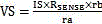
 。
。
referring to fig. 4, the power monitoring module 102 further includes a comparison control circuit, where the comparison control circuit includes a first comparator, a second comparator and an and circuit, one input end of the first comparator is connected to the output end of the first amplifier, the other input end of the first comparator is connected to a voltage corresponding to the preset current limit value, one input end of the second comparator is connected to a voltage on the communication signal line, the other input end of the second comparator is connected to the preset voltage, two input ends of the and circuit are respectively connected to the output ends of the first comparator and the second comparator, and the output end of the and circuit is connected to the control end of the power supply module to output the control signal.
The specific implementation process of the comparison control circuit is as follows: the amplified voltage VS is compared with a voltage V _ IREF corresponding to a predetermined current limit value. The implementation IS that VC1 IS high level when the current IS flowing through the sampling resistor Rsense IS less than the limiting current value, and VC1 IS low level when the current IS flowing through the sampling resistor Rsense IS greater than the limiting current value.
VSP is compared with a preset V _ VREF level, and VC2 is low when VSP is smaller than V _ VREF, and VC2 is high when VSP is larger than V _ VREF.
The VC1 and VC2 signal phases are anded to generate an SW signal, which is fed back to the power supply section of the main cell 100.
Referring to fig. 5, in another embodiment, the power supply module 101 includes a voltage regulator L DO and a relay R L1, the relay R L1 is connected to the output terminal of the voltage regulator L DO, the input terminal of the voltage regulator L DO is connected to the input power, the input terminal of the relay R L1 is connected to the output terminal of the voltage regulator L DO, the control terminal is connected to the control signal SW, the output terminal of the relay R L1 is the output terminal of the power supply module 101, and the relay R L1 controls the presence or absence of the power output to the communication signal line SP according to the control signal SW.
When communication IS not carried out on a communication signal line SPSP, an SP signal IS at a high level, VC2 IS at a high level, IS IS less than a limited current, VC1 IS at a high level, VOUT normally supplies power, when communication IS carried out on the SP signal, when a sending signal IS switched to a low level, a circuit monitors that IS IS greater than the limited current, VC1 IS at a low level, VSP IS less than V _ VREF, VC2 IS at a low level, SW IS at a low level, R L1 IS disconnected, VOUT power supply does not output, the current IS monitored to be 0, VC1 IS changed to be at the high level, but VSP IS still at the low level, therefore the VOUT power supply can not output all the time, and until the SP signal IS restored to be at the high level, SW signal IS changed to be at the high level again, and VOUT resumes supplying power.
In another embodiment, the unidirectional conducting module 204 includes a diode, and the high level voltage of the communication signal line SP is less than or equal to the maximum voltage value allowed to be input from the port of the unit 200. This approach has the advantage of simplicity, with only one component, where the SP high voltage does not exceed the maximum voltage allowed at the slave unit 200 port.
Referring to fig. 6, the unidirectional conducting module 204 may also be implemented by a PMOS transistor circuit, in which the unidirectional conducting module 204 further includes a fifth resistor R5, a sixth resistor R6, a seventh resistor R7, a PMOS transistor, and a transistor Q2, a D-pole of the PMOS transistor and one end of the fifth resistor R5 are connected to the communication signal line SP, the other end of the fifth resistor R5 and one end of the sixth resistor R6 are connected to the base of the transistor Q2, and the other end of the sixth resistor R6 and the emitter of the transistor Q2 are grounded; the G pole of the PMOS transistor and the collector of the transistor Q2 are connected to one end of the seventh resistor R7, and the S pole of the PMOS transistor and the other end of the seventh resistor R7 are connected to serve as the output end of the unidirectional conducting module 204. The specific process realized by the PMOS tube circuit is as follows: when SP is high, Q2 is turned on by R2 and R3 resistors. The G pole of the Q1 PMOS is pulled down to GND, and Q1 is turned on. The conduction power supply of the SP to the VCC1 is realized. When the SP signal is low, Q2 goes off. There is no voltage difference between G pole and S pole of Q1, and Q1 is cut off. The SP signal is disconnected from VCC1, effectively preventing VCC1 from back-sourcing the SP signal.
This approach has the advantage that the voltage drop between the SP and VCC1 is very small when conducting, and there is no need to specifically handle the supply voltage across the SP to prevent overvoltage from causing damage to the communication port.
The slave unit 200 further includes an energy storage module 201, one end of the energy storage module 201 is connected to the output end of the unidirectional conducting module 204, and the other end of the energy storage module 201 is grounded. The main functions of the energy storage part are as follows: when the SP signal line is at a low voltage and cannot supply power to the terminal unit, power is supplied to the slave unit 200 to normally operate. When the communication signal line SP is at a low voltage, the energy storage unit supplies power to the slave unit 200. The energy storage module 201 is a rechargeable battery or a capacitor. Using capacitors, the capacitance of the capacitors is required to be sufficient to support the slave unit 200 to operate properly during communication. The use of a rechargeable battery has the advantage of having a much larger capacity than the capacitance, which can support the operation of the slave unit 200 for a long time.
The detailed power supply and communication processes in the embodiments of the present invention are described in the following.
When there is no communication between the master unit 100 and the slave unit 200, the SP signal line is always in a high state. The a _ RX/TX port of the communication section 103 of the master unit 100 and the B _ RX/TX port of the communication section 202 of the slave unit 200 are both configured in the input mode, and the power supply section 101 supplies power to the slave unit 200 through the SP signal line and the unidirectional conduction D1.
The ports A _ RX/TX and B _ RX/TX work in an input mode, the input resistance of the ports A _ RX/TX and B _ RX/TX is very large, and the current flowing into the ports is very small and cannot be damaged due to the current.
The input voltage of the port is allowed to be larger than the working voltage of the corresponding unit, and the input voltage of the port is allowed to be larger than the working voltage of 0.3V in a general electronic system. When the voltage externally provided by the power supply part is greater than the operating voltage of the master unit 100 and the operating voltage of the slave unit 200, and is less than the +0.3V of the operating voltage of the master unit 100 and the +0.3V of the operating voltage of the slave unit 200, port damage is not caused.
The power supply of the power supply part 101 allows the terminal unit to operate normally while part of the electric energy is stored in the energy storage part 201. The energy storage part 201 may be constituted by a capacitor, a rechargeable battery, or the like, and the stored energy maintains the normal operation of the terminal unit when the SP communication line is low.
When there is communication between the master unit 100 and the slave unit 200 or between the slave units 200, the port of the communication initiating unit operates in the output mode, while the port of the receiving unit still operates in the input mode.
When a logic low level is transmitted on the SP signal line, the port of the communication initiating unit outputs a low level, and at this time, the power supply part power supply is pulled down to a low voltage through the port of the communication initiating unit, and the output current of the power supply part continuously increases. When the power supply monitoring part monitors that the current output by the power supply reaches a limit value, a specific control signal SW is given to the power supply part, and the power supply part receives the control signal and then achieves the function of protecting the port of the initiating unit by closing the output power supply or limiting the output current.
When the SP signal line transmits a logic high level, the port of the communication initiating unit outputs the high level, at the moment, the voltage monitoring part monitors the current and the voltage output by the power supply and then gives a control signal SW to the power supply part, and the power supply part restores to a normal power supply mode. And after the communication is finished, the communication initiating unit switches the communication port to an input mode.
The system realizes the communication function between the master unit 100 and the slave unit 200 and between the slave units 200 through the communication signal line.
The master unit 100 supplies power to the slave unit 200 through the communication signal line SP and has a protection function.
The slave unit 200 gets power from the signal line through the one-way conduction component, and the slave unit 200 can normally operate when the signal line does not provide power supply in the signal transmission process due to the energy storage part.
The present invention also provides a method for supplying power through a signal line, for supplying power between a master unit 100 and at least one slave unit 200, comprising the steps of: converting the input power into the working voltage required by the slave unit 200 through the processing of the master unit 100; when there is no communication between the master unit 100 and the slave unit 200, the slave unit 200 is supplied with power through the communication signal line SP; according to the presence or absence of the communication signal line SP, the power supply module 101 supplies power to the slave unit 200 according to the feedback signal of the power supply control module.
The communication signal line SP performs signal transmission using a standard logic level.
The method of supplying power through the signal line further includes the step of supplying power through the communication signal line SP when there is no communication between the master unit 100 and the slave unit 200.
When communication exists between the master unit 100 and the slave unit 200 and between the slave units 200, the port of the communication module initiated by communication is set to be in an output mode, when a logic 0 level is transmitted on a communication signal line SP, the port of the communication initiating unit outputs a low level, after monitoring that the current output by a power supply reaches a limit value, a set control signal is given, and the power supply is output or the output current is limited according to the control signal; when a logic high level is transmitted on the communication signal line SP, a port of the master unit 100 or the slave unit 200 initiated by the communication outputs the high level, the power supply monitoring module 102 monitors a current and voltage value output by the power supply module 101 and feeds the current and voltage value back to the power supply module 101, and the power supply module 101 supplies power through the communication signal line SP.
The above-described method of supplying power through a signal line the system of supplying power through a signal line realizes a communication function between the master unit 100, the slave unit 200, or the slave unit 200 through the communication signal line SP and the ground line GND.
The master unit 100 supplies power to the slave unit 200 through a communication signal and has a protection function.
The slave unit 200 gets power from the signal line through the one-way conduction component, and the slave unit 200 can normally operate when the signal line does not provide power supply in the signal transmission process due to the energy storage part.
Finally, it should be noted that: the above examples are only intended to illustrate the technical solution of the present invention, but not to limit it; although the present invention has been described in detail with reference to the foregoing embodiments, those of ordinary skill in the art will understand that: the technical solutions described in the foregoing embodiments may still be modified, or some technical features may be equivalently replaced; and such modifications or substitutions do not depart from the spirit and scope of the corresponding technical solutions of the embodiments of the present invention.
Claims (7)
1. A system for supplying power through a signal line, comprising: a master unit and at least one slave unit; the master unit is connected with the slave units through communication signal lines, the master unit at least comprises a power supply module, a power supply monitoring module and a master communication module, and any one of the slave units at least comprises a one-way conduction module and a slave communication module; the power supply module is connected with an input power supply, the control end of the power supply module is connected with the output end of the power supply monitoring module, one end of the communication signal wire is connected with the output end of the power supply module and the input/output port of the main communication module, the other end of the communication signal wire is connected with the input/output port of the slave communication module and one end of the one-way conduction module, and the input end of the power supply monitoring module is connected with the output end of the power supply module and the communication signal wire; the power supply module converts the accessed input power supply and outputs the converted output power supply through a communication signal line; the power supply monitoring module monitors a current value and a voltage value output by the power supply module through the communication signal line, and sends a control signal to the power supply module through an output end according to the current value and the voltage value, and the power supply module controls the converted output power supply according to the control signal; the master communication module and the slave communication module receive and transmit communication information through the communication signal line;
the power supply monitoring module comprises a current sampling amplifying circuit, wherein the current sampling amplifying circuit comprises a sampling resistor, a first resistor, a second resistor, a third resistor, a fourth resistor and a first amplifier; one end of the sampling resistor and one end of the first resistor are connected to the output end of the power supply module, and the other end of the sampling resistor and one end of the second resistor are connected to the communication signal line; the positive phase input end of the first amplifier is connected with the other end of the first resistor and one end of the third resistor, and the other end of the third resistor is grounded; the inverting input end of the first amplifier is connected with the other end of the second resistor and one end of the fourth resistor; the fourth resistor is connected between the output end and the inverting input end of the first amplifier in parallel;
the power supply monitoring module further comprises a comparison control circuit, wherein the comparison control circuit comprises a first comparator, a second comparator and an AND gate circuit, one input end of the first comparator is connected with the output end of the first amplifier, the other input end of the first comparator is connected with a voltage corresponding to a preset current limit value, one input end of the second comparator is connected with the voltage on the communication signal line, the other input end of the second comparator is connected with a preset voltage, the two input ends of the AND gate circuit are respectively connected with the output end of the first comparator and the output end of the second comparator, and the output end of the AND gate circuit is connected with the control end of the power supply module to output the control signal;
when the voltage of the output end of the first amplifier is smaller than the voltage corresponding to the preset current limit value and the voltage on the communication signal line is larger than the preset voltage, the control signal is at a high level, and the power supply module outputs a converted output power supply according to the control signal;
the power supply module comprises a voltage stabilizer and a relay which are connected with each other, wherein the input end of the voltage stabilizer is connected with an input power supply, the input end of the relay is connected with the output end of the voltage stabilizer, the control end of the relay is connected with the control signal, the output end of the relay is the output end of the power supply module, and the relay controls whether the power supply which is output to the communication signal wire exists or not according to the control signal;
when the communication signal line transmits a low level, the power supply monitoring module sends a control signal to the power supply module after monitoring that the current of the output power supply reaches a limit value, and the power supply module closes the output power supply or limits the output current after receiving the control signal.
2. The system for supplying power through a signal line according to claim 1, wherein when there is no communication between a master unit and a slave unit, the input/output ports of the master communication module and the slave communication module are both in an input mode, and the power supply module supplies power to the slave unit through the communication signal line and the unidirectional conducting module.
3. A system for supplying power through a signal line according to claim 1, wherein when the master unit and the slave units communicate with each other, an input/output port of a communication module of the master unit or the slave unit from which communication is initiated is in an output mode, and an input/output port of a communication module of the master unit or the slave unit which receives a communication signal is in an input mode;
when a high level is transmitted on a communication signal line, the power supply monitoring module sends a control signal to the power supply module after monitoring a current value and a voltage value output by the power supply module, and the power supply module restores a normal power supply mode according to the control signal and supplies power through the communication signal line.
4. The system for supplying power through a signal line according to claim 1, wherein the communication rates of the master communication module and the slave communication module are the same.
5. The system for supplying power through a signal line according to claim 1, wherein the unidirectional conducting module comprises a diode, and a high-level voltage input to the slave unit through the communication signal line is less than or equal to a maximum voltage value allowed to be input from a port of the slave unit.
6. The system for supplying power through a signal wire according to claim 1, wherein the unidirectional conducting module comprises a fifth resistor, a sixth resistor, a seventh resistor, a PMOS transistor, and a transistor, wherein a D pole of the PMOS transistor and one end of the fifth resistor are connected to the communication signal wire, the other end of the fifth resistor and one end of the sixth resistor are connected to a base of the transistor, and the other end of the sixth resistor and an emitter of the transistor are grounded; and the G pole of the PMOS tube and the collector electrode of the triode are connected with one end of a seventh resistor, and the S pole of the PMOS tube and the other end of the seventh resistor are connected and used as the output end of the unidirectional conduction module.
7. The system according to claim 1, wherein the slave unit further comprises an energy storage module, one end of the energy storage module is connected to the output end of the unidirectional conducting module, the other end of the energy storage module is grounded, and when the voltage on the communication signal line is low and cannot supply power to the slave unit, the energy storage module supplies power to the slave unit.
Priority Applications (1)
| Application Number | Priority Date | Filing Date | Title |
|---|---|---|---|
| CN201710630537.XA CN107196770B (en) | 2017-07-28 | 2017-07-28 | System for supplying power through signal wire |
Applications Claiming Priority (1)
| Application Number | Priority Date | Filing Date | Title |
|---|---|---|---|
| CN201710630537.XA CN107196770B (en) | 2017-07-28 | 2017-07-28 | System for supplying power through signal wire |
Publications (2)
| Publication Number | Publication Date |
|---|---|
| CN107196770A CN107196770A (en) | 2017-09-22 |
| CN107196770B true CN107196770B (en) | 2020-08-04 |
Family
ID=59884804
Family Applications (1)
| Application Number | Title | Priority Date | Filing Date |
|---|---|---|---|
| CN201710630537.XA Active CN107196770B (en) | 2017-07-28 | 2017-07-28 | System for supplying power through signal wire |
Country Status (1)
| Country | Link |
|---|---|
| CN (1) | CN107196770B (en) |
Families Citing this family (2)
| Publication number | Priority date | Publication date | Assignee | Title |
|---|---|---|---|---|
| CN107610734B (en) * | 2017-09-30 | 2020-12-25 | 上海贝岭股份有限公司 | Power supply circuit of EEPROM and EEPROM |
| CN110611574B (en) * | 2019-10-28 | 2021-03-09 | 中国兵器工业集团第二一四研究所苏州研发中心 | Bidirectional communication interface circuit based on current sampling |
Citations (5)
| Publication number | Priority date | Publication date | Assignee | Title |
|---|---|---|---|---|
| CN103795033A (en) * | 2014-03-04 | 2014-05-14 | 东南大学 | Detecting and protecting circuit and method for inter-phase short circuit of switch reluctance motor |
| CN103823776A (en) * | 2014-02-28 | 2014-05-28 | 上海晟矽微电子股份有限公司 | Unibus in communication with master equipment and slave equipment and communication method |
| CN103904743A (en) * | 2014-03-28 | 2014-07-02 | 常州信息职业技术学院 | High-performance parasitic power supply method and structure |
| CN203979586U (en) * | 2014-07-23 | 2014-12-03 | 东风汽车公司 | A kind of multipath electrovalve flash control and flash current sampling circuit |
| CN104503524A (en) * | 2014-11-18 | 2015-04-08 | 北京七芯中创科技有限公司 | Circuit structure capable of selecting between external power supply and parasite power supply |
Family Cites Families (1)
| Publication number | Priority date | Publication date | Assignee | Title |
|---|---|---|---|---|
| US20070027655A1 (en) * | 2005-07-26 | 2007-02-01 | Schmidt Dennis E | Aircraft component condition monitoring system based on electronic serialisation |
-
2017
- 2017-07-28 CN CN201710630537.XA patent/CN107196770B/en active Active
Patent Citations (5)
| Publication number | Priority date | Publication date | Assignee | Title |
|---|---|---|---|---|
| CN103823776A (en) * | 2014-02-28 | 2014-05-28 | 上海晟矽微电子股份有限公司 | Unibus in communication with master equipment and slave equipment and communication method |
| CN103795033A (en) * | 2014-03-04 | 2014-05-14 | 东南大学 | Detecting and protecting circuit and method for inter-phase short circuit of switch reluctance motor |
| CN103904743A (en) * | 2014-03-28 | 2014-07-02 | 常州信息职业技术学院 | High-performance parasitic power supply method and structure |
| CN203979586U (en) * | 2014-07-23 | 2014-12-03 | 东风汽车公司 | A kind of multipath electrovalve flash control and flash current sampling circuit |
| CN104503524A (en) * | 2014-11-18 | 2015-04-08 | 北京七芯中创科技有限公司 | Circuit structure capable of selecting between external power supply and parasite power supply |
Non-Patent Citations (2)
| Title |
|---|
| 一种改进的寄生供电串行通信总线及其收发器;王峻松;《微电子学》;20071231;第37卷(第6期);正文第1-5页 * |
| 王峻松.一种改进的寄生供电串行通信总线及其收发器.《微电子学》.2007,第37卷(第6期),正文第1-5页. * |
Also Published As
| Publication number | Publication date |
|---|---|
| CN107196770A (en) | 2017-09-22 |
Similar Documents
| Publication | Publication Date | Title |
|---|---|---|
| US10664029B2 (en) | Power supply apparatus and power receiving apparatus | |
| US11646585B2 (en) | Methods, electronic devices, and charger apparatus for quick USB charging | |
| US9960617B2 (en) | Mobile terminal with multi-port charging control function | |
| CN109150551B (en) | Non-standard POE power supply circuit, power supply equipment and power supply method for network port | |
| US9787120B2 (en) | Usb charger, mobile terminal and charging method thereof | |
| US9130400B2 (en) | Multiport power converter with load detection capabilities | |
| CN106100858B (en) | Standard POE and force non-standard POE integration to receive power supply circuit | |
| KR100775992B1 (en) | Device operable as a host | |
| EP3221999B1 (en) | Power over ethernet powered device automatic maintaining power signature | |
| CN104239240A (en) | Electronic device with universal serial bus (USB) interface with integration function | |
| US11588402B2 (en) | Systems and methods for charging a battery | |
| CN107453427B (en) | CAN signal wake-up circuit | |
| CN101127608A (en) | Wireless network adapter over current protection method and device | |
| CN107196770B (en) | System for supplying power through signal wire | |
| CN105549712B (en) | A kind of method of supplying power to, power supply mould group and electronic equipment | |
| CN110829839A (en) | Power supply control device and control apparatus | |
| US10804883B2 (en) | Power supply apparatus and master power supply circuit, slave power supply circuit and control method thereof | |
| US10461555B2 (en) | Battery charging for mobile devices | |
| CN113037508B (en) | Power-down control circuit and power-down control method | |
| US20240088678A1 (en) | Voltage balancing system | |
| CN107942125B (en) | Power utilization testing circuit of built-in battery type electronic product and control method thereof | |
| US20180145525A1 (en) | Charging managment method and system thereof | |
| US11182331B2 (en) | Communication system and communication unit | |
| CN105915050A (en) | I2C controlled four-channel outputting adjustable power supply managing system | |
| CN110912239A (en) | Multi-port charging equipment |
Legal Events
| Date | Code | Title | Description |
|---|---|---|---|
| PB01 | Publication | ||
| PB01 | Publication | ||
| SE01 | Entry into force of request for substantive examination | ||
| SE01 | Entry into force of request for substantive examination | ||
| GR01 | Patent grant | ||
| GR01 | Patent grant |