CN106913366B - On-tool tracking system and computer-assisted surgery method - Google Patents
On-tool tracking system and computer-assisted surgery method Download PDFInfo
- Publication number
- CN106913366B CN106913366B CN201710074093.6A CN201710074093A CN106913366B CN 106913366 B CN106913366 B CN 106913366B CN 201710074093 A CN201710074093 A CN 201710074093A CN 106913366 B CN106913366 B CN 106913366B
- Authority
- CN
- China
- Prior art keywords
- ott
- tool
- surgical
- computer
- cas
- Prior art date
- Legal status (The legal status is an assumption and is not a legal conclusion. Google has not performed a legal analysis and makes no representation as to the accuracy of the status listed.)
- Active
Links
Images


Classifications
-
- A—HUMAN NECESSITIES
- A61—MEDICAL OR VETERINARY SCIENCE; HYGIENE
- A61B—DIAGNOSIS; SURGERY; IDENTIFICATION
- A61B34/00—Computer-aided surgery; Manipulators or robots specially adapted for use in surgery
- A61B34/20—Surgical navigation systems; Devices for tracking or guiding surgical instruments, e.g. for frameless stereotaxis
-
- A—HUMAN NECESSITIES
- A61—MEDICAL OR VETERINARY SCIENCE; HYGIENE
- A61B—DIAGNOSIS; SURGERY; IDENTIFICATION
- A61B17/00—Surgical instruments, devices or methods, e.g. tourniquets
- A61B17/16—Bone cutting, breaking or removal means other than saws, e.g. Osteoclasts; Drills or chisels for bones; Trepans
- A61B17/17—Guides or aligning means for drills, mills, pins or wires
- A61B17/1703—Guides or aligning means for drills, mills, pins or wires using imaging means, e.g. by X-rays
-
- A—HUMAN NECESSITIES
- A61—MEDICAL OR VETERINARY SCIENCE; HYGIENE
- A61B—DIAGNOSIS; SURGERY; IDENTIFICATION
- A61B17/00—Surgical instruments, devices or methods, e.g. tourniquets
- A61B17/14—Surgical saws ; Accessories therefor
-
- A—HUMAN NECESSITIES
- A61—MEDICAL OR VETERINARY SCIENCE; HYGIENE
- A61B—DIAGNOSIS; SURGERY; IDENTIFICATION
- A61B17/00—Surgical instruments, devices or methods, e.g. tourniquets
- A61B17/14—Surgical saws ; Accessories therefor
- A61B17/142—Surgical saws ; Accessories therefor with reciprocating saw blades, e.g. with cutting edges at the distal end of the saw blades
-
- A—HUMAN NECESSITIES
- A61—MEDICAL OR VETERINARY SCIENCE; HYGIENE
- A61B—DIAGNOSIS; SURGERY; IDENTIFICATION
- A61B17/00—Surgical instruments, devices or methods, e.g. tourniquets
- A61B17/16—Bone cutting, breaking or removal means other than saws, e.g. Osteoclasts; Drills or chisels for bones; Trepans
- A61B17/1613—Component parts
- A61B17/1626—Control means; Display units
-
- A—HUMAN NECESSITIES
- A61—MEDICAL OR VETERINARY SCIENCE; HYGIENE
- A61B—DIAGNOSIS; SURGERY; IDENTIFICATION
- A61B17/00—Surgical instruments, devices or methods, e.g. tourniquets
- A61B17/16—Bone cutting, breaking or removal means other than saws, e.g. Osteoclasts; Drills or chisels for bones; Trepans
- A61B17/1662—Bone cutting, breaking or removal means other than saws, e.g. Osteoclasts; Drills or chisels for bones; Trepans for particular parts of the body
- A61B17/1675—Bone cutting, breaking or removal means other than saws, e.g. Osteoclasts; Drills or chisels for bones; Trepans for particular parts of the body for the knee
-
- A—HUMAN NECESSITIES
- A61—MEDICAL OR VETERINARY SCIENCE; HYGIENE
- A61B—DIAGNOSIS; SURGERY; IDENTIFICATION
- A61B17/00—Surgical instruments, devices or methods, e.g. tourniquets
- A61B17/16—Bone cutting, breaking or removal means other than saws, e.g. Osteoclasts; Drills or chisels for bones; Trepans
- A61B17/17—Guides or aligning means for drills, mills, pins or wires
- A61B17/1739—Guides or aligning means for drills, mills, pins or wires specially adapted for particular parts of the body
- A61B17/1764—Guides or aligning means for drills, mills, pins or wires specially adapted for particular parts of the body for the knee
-
- A—HUMAN NECESSITIES
- A61—MEDICAL OR VETERINARY SCIENCE; HYGIENE
- A61B—DIAGNOSIS; SURGERY; IDENTIFICATION
- A61B34/00—Computer-aided surgery; Manipulators or robots specially adapted for use in surgery
- A61B34/30—Surgical robots
-
- A—HUMAN NECESSITIES
- A61—MEDICAL OR VETERINARY SCIENCE; HYGIENE
- A61B—DIAGNOSIS; SURGERY; IDENTIFICATION
- A61B34/00—Computer-aided surgery; Manipulators or robots specially adapted for use in surgery
- A61B34/30—Surgical robots
- A61B34/32—Surgical robots operating autonomously
-
- A—HUMAN NECESSITIES
- A61—MEDICAL OR VETERINARY SCIENCE; HYGIENE
- A61B—DIAGNOSIS; SURGERY; IDENTIFICATION
- A61B34/00—Computer-aided surgery; Manipulators or robots specially adapted for use in surgery
- A61B34/70—Manipulators specially adapted for use in surgery
- A61B34/76—Manipulators having means for providing feel, e.g. force or tactile feedback
-
- A—HUMAN NECESSITIES
- A61—MEDICAL OR VETERINARY SCIENCE; HYGIENE
- A61B—DIAGNOSIS; SURGERY; IDENTIFICATION
- A61B34/00—Computer-aided surgery; Manipulators or robots specially adapted for use in surgery
- A61B34/10—Computer-aided planning, simulation or modelling of surgical operations
- A61B2034/101—Computer-aided simulation of surgical operations
- A61B2034/102—Modelling of surgical devices, implants or prosthesis
-
- A—HUMAN NECESSITIES
- A61—MEDICAL OR VETERINARY SCIENCE; HYGIENE
- A61B—DIAGNOSIS; SURGERY; IDENTIFICATION
- A61B34/00—Computer-aided surgery; Manipulators or robots specially adapted for use in surgery
- A61B34/20—Surgical navigation systems; Devices for tracking or guiding surgical instruments, e.g. for frameless stereotaxis
- A61B2034/2046—Tracking techniques
- A61B2034/2055—Optical tracking systems
- A61B2034/2057—Details of tracking cameras
-
- A—HUMAN NECESSITIES
- A61—MEDICAL OR VETERINARY SCIENCE; HYGIENE
- A61B—DIAGNOSIS; SURGERY; IDENTIFICATION
- A61B90/00—Instruments, implements or accessories specially adapted for surgery or diagnosis and not covered by any of the groups A61B1/00 - A61B50/00, e.g. for luxation treatment or for protecting wound edges
- A61B90/06—Measuring instruments not otherwise provided for
- A61B2090/064—Measuring instruments not otherwise provided for for measuring force, pressure or mechanical tension
-
- A—HUMAN NECESSITIES
- A61—MEDICAL OR VETERINARY SCIENCE; HYGIENE
- A61B—DIAGNOSIS; SURGERY; IDENTIFICATION
- A61B90/00—Instruments, implements or accessories specially adapted for surgery or diagnosis and not covered by any of the groups A61B1/00 - A61B50/00, e.g. for luxation treatment or for protecting wound edges
- A61B90/36—Image-producing devices or illumination devices not otherwise provided for
- A61B2090/364—Correlation of different images or relation of image positions in respect to the body
- A61B2090/366—Correlation of different images or relation of image positions in respect to the body using projection of images directly onto the body
-
- A—HUMAN NECESSITIES
- A61—MEDICAL OR VETERINARY SCIENCE; HYGIENE
- A61B—DIAGNOSIS; SURGERY; IDENTIFICATION
- A61B90/00—Instruments, implements or accessories specially adapted for surgery or diagnosis and not covered by any of the groups A61B1/00 - A61B50/00, e.g. for luxation treatment or for protecting wound edges
- A61B90/36—Image-producing devices or illumination devices not otherwise provided for
- A61B90/37—Surgical systems with images on a monitor during operation
- A61B2090/371—Surgical systems with images on a monitor during operation with simultaneous use of two cameras
Abstract
Many improvements are provided with respect to computer assisted surgery utilizing an on-tool tracking system. Various improvements generally relate to methods used in computer-assisted surgical procedures and devices used in such procedures. Other improvements relate to the structure of the tool used during the procedure and how the tool can be controlled using the OTT device. Still other improvements relate to methods of providing feedback during a procedure to improve the efficiency, quality, or both for procedures that include the rate and type of data processed according to the CAS mode.
Description
The application has an application date of 2012, month 06, month 27 and an international application number of: PCT/US2012/044486, national application number: 201280042066.6, divisional application of international application entering the national phase of china entitled "on-tool tracking system and computer-assisted surgery method".
Cross Reference to Related Applications
This application claims benefit from U.S. provisional patent application No.61/501489 entitled "SYSTEM FOR coordinated NAVIGATION AND CONTROL OF a POWER TOOL", filed 2011, 6, month 27, in accordance with 35u.s.c. 119. This provisional application is incorporated herein by reference in its entirety.
Is incorporated by reference
All publications and patent applications mentioned in this specification are herein incorporated by reference to the same extent as if each individual publication or patent application was specifically and individually indicated to be incorporated by reference.
Statement regarding federally sponsored research
The invention was made with government support under grant No.0578104 awarded by the department of defense. The government has certain rights in the invention.
Technical Field
The present invention relates to the field of computer-assisted surgery. In particular, the present invention relates to various aspects of a surgical suite in which an on-tool tracking system provides guidance or assistance during a surgical procedure.
Background
Many surgical procedures are complex procedures requiring numerous alignment fixtures and intricate soft tissue procedures. Preparation and placement of alignment jigs and other preparations are often an important part of the procedure. For example, when performing total knee replacement surgery ("TKR"), the prosthesis must be accurately implanted to ensure that the articular surfaces are properly aligned. If not properly aligned, misalignment can ultimately lead to failure of the joint, requiring the complex task of replacing one or more portions of the knee prosthesis.
To ensure that the prosthesis is accurately implanted, surgeons use a variety of jigs to guide the cutting of the femur and tibia during TKR surgery. A clamp is a complex device that requires more time and skill to position and attach to a patient during a surgical procedure.
The advent of Computer Assisted Surgery (CAS) has provided the promise of simplifying many of the complexities of surgery. To date, systems have evolved that utilize individual room-based tracking systems designed to monitor cutting jigs, tools, and patients. In some cases, the computer may be used to guide the surgeon during the procedure. Arrangements have been proposed in which the camera in the room is closer to the tool. However, improvements are needed to address the challenges of the real-time and dynamic environment of surgery.
While computer-assisted surgery is promising, there are numerous aspects to address to make the system commercially interesting and useful to the surgeon. There are still many aspects of computer assisted surgery that require improvements to improve the efficiency and/or quality of the procedure for the processing of CAS data and more useful output to the user.
Disclosure of Invention
In one aspect, a haptic feedback mechanism includes: a first platform; a second platform; a scissor linkage coupled to the second linkage by a first linkage, the scissor linkage extending between the first platform and the second platform, wherein a first end of the first linkage is coupled to the first platform, a second end of the first linkage is coupled to the second platform, a first end of the second linkage is coupled to the first platform, and a second end of the second linkage is coupled to the second platform; and at least one position restoration element coupled to the scissor linkage to adjust a force response of the relative movement between the first platform and the second platform. In some aspects, the at least one position restoration element is coupled between the first end of the first coupling mechanism and the second end of the second coupling mechanism. In another aspect, at least one position restoration element extends along the second platform and is coupled to the scissor linkage to adjust movement of the second linkage second end relative to the second platform. In one embodiment, the first platform and the second platform are operable alongside, partially covering, partially surrounding, partially over, or completely over a trigger of the surgical tool. In one embodiment, a trigger cover is disposed within the first platform for engagement with the trigger.
In another configuration of the tactile feedback mechanism, at least one position restoration element coupled to the scissor linkage to adjust a force response of the relative movement between the first platform and the second platform is coupled to extend between the first platform and the second platform. Additionally, a position restoration element coupled to the scissor linkage and extending along the second platform may be provided. In one particular configuration of the tactile feedback mechanism, the position restoration element is a return spring coupled to the second end of the second coupling mechanism; the override spring is coupled to the return spring and may also have an actuator coupled to the override spring. In another embodiment of the tactile feedback mechanism, the position restoration element is a spring tension-coupled in accordance with the movement of the second end of the scissor linkage relative to the second platform. In another position restoring element configuration, the spring compresses the link in accordance with movement of the second end of the scissor linkage relative to the second platform. In some feedback mechanisms, there is also a shaft extending from an opening in the second platform and coupled to the scissor linkage, wherein movement of the scissor linkage produces a corresponding movement of the shaft relative to the opening. Alternatives to a shaft include, for example, a flexible shaft portion, a cable portion, a hollow shaft portion, or a flexible coupling mechanism portion.
In other configurations, embodiments of the haptic feedback mechanism may be used in conjunction with embodiments of an on-tool tracking device that can be used in computer-assisted surgery. Such OTT devices include components or a series of cooperating components, for example, within an on-tool tracking device, which are capable of translating axial relative motion into signals for use in computer-assisted surgery. In an aspect, the component may be an actuator, solenoid, motor, potentiometer, linear potentiometer, or linear encoder, or other device positioned adjacent to the cable to register and measure the displacement of the cable. In one aspect, the cable motion involves a signal indicative of operation of a trigger of the surgical tool. In further embodiments, the same or different components may also be used as actuators to impart motion to the shaft to affect relative motion between the first and second platforms. These various components and functions are utilized with the support of being able to impart motion to or respond to the shaft in response to signals related to controlling the operation of the surgical tool during computer-assisted surgery.
In another embodiment, a frame of reference for use in computer-assisted surgery is provided. The frame of reference comprises: a frame having a surface bounded by a perimeter; a rod extending from the frame; a link on the rod; a base having a first surface configured to engage a portion of an anatomical structure within a surgical field associated with a procedure and a second surface to engage the coupling. In some configurations, at least one registration element on the link and at least one registration element on the second surface may also be provided, wherein the registration elements are operable for mating cooperation when the link is engaged to the second surface. In further configurations, a plurality of registration elements on the link; and a plurality of registration elements on the second surface, wherein a portion of the registration elements on the link, when engaged with a portion of the registration elements on the second surface, orient the frame in a first orientation within the surgical field. In one aspect, movement between links in the second surface to engage other registration elements of the plurality of registration elements positions the frame in a different second orientation within the surgical field. In some aspects, the first orientation and the second orientation are known locations and are used in surgical preplanning. The frame of reference may include other features, such as surfaces for engaging anatomical structures, apertures for fixation elements, or configurations to mate with specific anatomical objects. In another aspect, there is provided a reference frame according to claim C1, further comprising: a reference frame guide having a frame and a rod extending from the frame, wherein the rod has a curvature or shape engageable with an anatomical feature to assist in placement of the reference frame. In an aspect, the reference frame guide further comprises: one or more engagement elements along the frame for temporary engagement with a perimeter or portion of the reference frame to allow proper positioning and adjustment of a base associated with the reference frame. In one aspect, a portion of the bony anatomy relates to the placement of the rod relative to the condyle. In another aspect, the reference frame includes a mounting link capable of maintaining the relative position and orientation of the link and the second surface. In one aspect, the mounting link is disposed in the reference frame such that when the mounting link is mated to the base, the mounting link is located in an interior portion of the reference frame. In another aspect, the mounting link is disposed in the reference frame such that when the mounting link is attached to the reference frame, the mounting link substantially or completely surrounds a mating contact area between the link and the second surface.
In an alternative embodiment, a method of performing a computer-assisted surgical procedure within a surgical field is provided. First, attaching a first reference frame at a first location within a surgical field; then, attaching a second frame of reference at a second location within the surgical field; and thereafter, initiating actual steps of the procedure using the surgical tool while maintaining positioning information obtained from the first and second reference frames for use during the computer-assisted surgery procedure. In an alternative aspect, there is the step of adjusting the position of the surgical tool relative to the segment of the anatomy during or as part of the procedure while maintaining positioning information obtained from the first and/or second reference frames attached to the segment of the anatomy for use during the computer-assisted surgery procedure. In an alternative embodiment, there is the step of hovering the surgical tool during or as part of the procedure while maintaining positioning information obtained from the first and/or second reference frames for use during the computer-assisted surgical procedure. In another aspect, a method includes performing one or more of the initiating, adjusting, or hovering steps in one or more steps that facilitate a computer-assisted surgery on a knee. In another alternative, the method includes one or more steps of computer-assisted surgery on the knee, including: making a distal lateral condyle incision, making a distal medial condyle incision, making an anterior incision, making a posterior lateral condyle incision, making a posterior medial condyle incision, making an anterior chamfer incision, making a posterior lateral condyle chamfer incision, making a posterior medial condyle chamfer incision, making a femoral box incision, drilling a hole in a portion of a surgical site, and making a tibial incision. In another alternative embodiment, the method proceeds with changing an orientation of a portion of the reference frame relative to the surgical field while maintaining the first and second reference frames in the first and second positions, respectively, after the attaching step is completed, and then using position information from the changed orientation for a portion of the computer-assisted surgery. In another aspect, position information relating to the orientation of the first and second reference frames in the initial and altered orientations is used as part of a pre-planned procedure for computer-assisted surgery.
In another alternative embodiment, an on-tool tracking and guidance device is provided. In one aspect, an apparatus has: a housing having a surface for releasable engagement with a portion of a surgical tool; a first camera and optionally a second camera in an arrangement in which both the first camera and the second camera (if provided) provide image output for viewing substantially all or a portion of a surgical region selected for computer-assisted surgery. In one aspect, the OTT device may include a simple output device for communicating information to the user about the OTT CAS process being performed. In other aspects, the OTT device may include a projector configured to provide an output at least partially within the surgical field of view. Various embodiments of the OTT device described herein may combine multiple capabilities for electronic image processing and image communication capabilities within the housing. In addition, additional embodiments are capable of receiving output from each of one, two or more cameras provided by embodiments of the OTT device. Additionally or alternatively, the electronics and processing capabilities of OTT devices may be utilized to perform a number of various digital processing functions. In one aspect, the OTT includes electronics that perform image processing operations using at least a portion of the output from the two cameras for use in computer-assisted surgery. In one aspect, the camera selected for the OTT device includes a viewing area from about 70mm to about 200mm, or optionally from about 50mm to 250mm, from the first camera and the second camera. Other ranges and camera configurations may be used in various other embodiments.
In another embodiment, the OTT housing surface for releasable engagement with a portion of a surgical tool is shaped to form a complementary arc with a portion of the surgical tool or a portion of a modified surgical tool selected for engagement with the housing, and in some cases, a portion of the surgical tool is modified to accommodate releasable engagement with the housing surface. In one example, the surface for releasable engagement with a portion of the surgical tool can be configured such that, when the surface is coupled to the surgical tool, at least a portion of the active section of the surgical tool is located within the horizontal viewing region and the vertical viewing region.
In further aspects, the projector may include attributes such as: the output from the projector is projected on or near a movable element associated with a surgical tool attached to the housing; the output from the projector can be projected on a portion of the patient's anatomy, or on or within the surface of a surgical region in a surgical scene; the adjustment process gives an adjusted projector output, which is adjusted for the curvature, roughness or state of the anatomy. In one aspect, the projector is a pico projector.
In one embodiment, a method of performing a computer-assisted surgical procedure using a handheld surgical instrument having an on-tool tracking device attached thereto is provided, the method comprising: collecting and processing computer-assisted surgical data using an on-tool tracking device; evaluating data in real time during a computer-assisted surgery; performing, with the on-tool tracking device, a CAS-related operation selected from at least two of: controlling the operation of the tool, controlling the speed of the tool and providing guidance to the user regarding the CAS step; controlling the operation or speed of the tool, or providing guidance to the user to adjust the speed of the tool; and providing an output related to the evaluating step to a user of the surgical instrument. In additional or alternative aspects, there may also be one or more of displaying, projecting, or indicating output related to the computer-assisted surgical procedure.
In additional or alternative aspects, there may also be an output comprising one or more of a tactile indication, a haptic indication, an audible indication, or a visual indication; the tactile indication comprises a temperature indication; and the tactile indication comprises a force indication or a vibration indication. In further aspects, the output is a control signal automatically generated to adjust a performance parameter of the surgical tool in response to the result of the evaluating step. In other aspects, the performance parameter includes modifying a cutting speed of the tool or stopping operation of the tool, and the output of the providing step further includes electronics to control operation of the power tool (modifying the cutting speed and/or stopping it). In additional or alternative aspects, there may also be a determination step based on an assessment of one or more of: physical parameters within the surgical field, such as the position or combination of positions of elements tracked within the field via an attached reference frame, reference frame input, images with projections, motion detected from sensors, motion detection from calculations, overall progress of the computer assisted surgery, measured or predicted deviations from previously prepared computer assisted surgery plans. In addition, the determining step selects one of a number of predetermined processing modes, such as, for example, a hover mode, a site approach mode, and an actual step mode. In each of these modes, there is a specific output, processing technique, and algorithm applied to the CAS data.
In further aspects, there is an OTT CAS processing mode factor selected from one or more of the following: a camera frame size; OTT camera orientation; adjustments to the camera software program or firmware according to the desired adjustments; adjustment of OTT camera or other camera image output to modify the size of the camera's horizontal viewing area, vertical viewing area, or areas of interest within both horizontal and vertical viewing areas; a drive signal for adjustable camera lens adjustment or positioning; an image frame rate; image output quality; a refresh rate; capturing a frame rate; a second reference frame; a first reference frame; starting reference frame benchmark selection; closing the reference frame reference selection; visual spectrum processing; IR spectrum processing; processing a reflection spectrum; LED or illumination spectrum processing; surgical tool motor/actuator speed and direction, total CAS procedure progression; the specific CAS step progression; modifying the image data array; the OTT micro-projector refresh rate; OTT miniature projector accuracy; one or more image segmentation techniques; one or more logic-based fetches of image portions based on CAS progression; adjusting the signal-to-noise ratio; one or more image magnification processes; one or more image filtering processes; applying a weighted average or other factor to the image rate, dynamic, real-time enhancement or reduction of pixel or sub-pixel visual processing; hand tremor compensation; instrument-based noise compensation for saws, drills, or other electrosurgical tools and vibration compensation procedures based on information from the OTT alone or in any combination.
In other aspects, the output is provided to the user using a projector in the on-tool tracking device. In addition, the projector output is adjusted based on physical characteristics of the surgical site presented during the display of the projector output. It will be appreciated that the physical characteristic is one or more of the shape of the portion of the size available to the projector output, the distribution in the area projected by the projector, and the orientation of the projector to the portion of the location available for the projector output. Optionally, a projector or display on the OTT device has an output that includes information that can be seen by a user of the surgical tool while the surgical tool is in use in the surgical site. In a further aspect, the projector or display output on the OTT device includes information that a user of the surgical tool can see to indicate a position, relative motion, orientation, or other guidance parameter related to the positioning of the active element of the surgical tool within the surgical field according to the surgical plan. The step of providing output from the OTT device may further comprise displaying the output on a GUI interface on the screen of the system, on the OTT or on the screen of the mobile device.
In another aspect, any of the above steps of outputting a CAS output to the user optionally changes and OTT CAS processing techniques or output modifications as a result of the user performing one or more steps of a computer-assisted surgery on a lap, the one or more steps comprising: making a femoral distal lateral condyle incision, making a femoral distal medial condyle incision, making a femoral distal anterior incision, making a femoral distal posterior lateral condyle incision, making a femoral distal posterior medial condyle incision, making a femoral distal anterior chamfer incision, making a femoral distal posterior lateral condyle chamfer incision, making a femoral distal posterior medial condyle chamfer incision, making a tibial proximal incision. In other alternatives, the method of outputting the CAS output to the user herein varies as a result of one of the above steps performed during a surgical procedure associated with one of a shoulder, a hip, an ankle, a vertebra, or an elbow. Additionally, the OTT CAS processing technique or output is modified as a result of one of the above steps performed during a surgical procedure related to one of the shoulder, hip, ankle, vertebra or elbow.
In a further aspect, there is provided a system for performing computer-assisted surgery having: a surgical tool having a movable element corresponding to a surgical function of the tool; a tool-carried tracking device coupled to the tool with a housing engageable with at least a portion of the surgical tool; at least one camera in the housing configured to obtain image information relating to the surgical tool and the surgical field; a display-like output device, or optionally a projector in the housing, capable of providing a projected output on or near the active element of the surgical tool; a computer having computer readable instructions stored in the electronic memory for performing a computer assisted surgical procedure using data obtained at least in part from the on tool tracking device and providing an output for use during the surgical step. When the system includes a projector within OTT capability, the projector further includes one or more of: projection capabilities to project output on a portion of the patient's anatomy, surfaces within a surgical scene, electronics, or other objects within the output range of the projector. In one configuration, the computer is in a housing. In another configuration, the computer is separate from the on-tool tracking device and connected via a wired or wireless connection. In further aspects, the system includes one or more of the computer readable instructions for performing any of the CAS mode selection methods described above. In another aspect, a system may include an on-tool tracking device having one or more of the above-described elements. The system may be adapted and configured for use with one or more of the frames of reference and related methods described herein. In another aspect, the system may be adapted and configured for use in conjunction with the haptic feedback mechanisms described herein.
Drawings
The novel features of the invention are set forth with particularity in the appended claims. A better understanding of the features and advantages of the present invention will be obtained by reference to the following detailed description that sets forth illustrative embodiments, in which the principles of the invention are utilized, and the accompanying drawings of which:
fig. 1 illustrates an isometric view of a tool-borne tracking device attached to a surgical instrument.
Fig. 2 illustrates an isometric view of a tool-borne tracking device attached to a surgical instrument.
Fig. 3 illustrates an isometric view of the tool-borne tracking device of fig. 1 with the cover removed to reveal internal components.
Fig. 4 illustrates an isometric view of the tool-borne tracking device of fig. 2 with the cover removed to reveal internal components.
Fig. 5 illustrates a top view of the on tool tracking device of fig. 4.
Fig. 6 illustrates an isometric view of the tool-borne tracking device of fig. 5 separated from a surgical tool.
Fig. 7 illustrates the electronics package and control circuitry seen in fig. 5 and 6 but removed from the OTT enclosure in this view.
Figures 8A, 8B, 9 and 10 provide graphical information relating to changes in camera area based on camera angle in some OTT device configurations.
11A, 11B, 11C, and 11D provide additional information regarding the change in camera angle.
Fig. 12A and 13A provide a side view and an isometric view, respectively, of a projector for use with an on-tool tracking device.
Fig. 12B, 13B, and 13C provide side, isometric, and top views, respectively, of a projector in an angular orientation for use with an on-tool tracking device.
14A, 14B, 15A, and 15B each illustrate a schematic view of several different electronic component configurations used by some on-tool tracking device embodiments.
Fig. 16A, 16B, and 16C illustrate various views of a reference frame.
Fig. 17 illustrates an isometric view of a reference frame guide, and fig. 18 illustrates the guide of fig. 17 attached to the reference frame of fig. 16A.
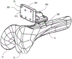
Fig. 19 illustrates the components of fig. 18 moved and positioned for attachment to an anatomical structure, and fig. 20 is an isometric view illustrating the attachment.
Fig. 21 illustrates removal of the guide frame, and fig. 22 illustrates holding the frame in place on the anatomy.
Fig. 23 illustrates another reference frame in place on the tibia.
Fig. 24A, B and C illustrate the reference frame and its components.
Fig. 25 illustrates an implant site on a tibia.
26A, 26B, and 26C illustrate another reference frame embodiment having a flexible coupling mechanism that joins the components of the frame.
Fig. 27A and 27B illustrate alternative reference frame surfaces.
FIG. 28 is an isometric view of an exemplary knee prosthesis.
Figures 29A-29I and 30 illustrate various views of an in-place, tool-borne tracking system and associated surgical tools for performing a total knee replacement OTT CAS procedure.
FIG. 31A is a flow chart representing an exemplary OTT CAS method.
FIG. 31B is a flow chart providing additional detail for performing processing steps using the method described in FIG. 31A.
FIG. 32 is a flowchart providing exemplary additional details of the process steps for determining the CAS processing mode.
FIG. 33 is a flow chart illustrating many factors that are considered inputs and representative outputs for determining a CAS processing mode.
FIG. 34 is a flow chart representing exemplary OTT CAS mode adjustment processing factors, site approach mode, and actual step mode to determine processing load for hover mode.
FIG. 35 is a flow diagram representing an exemplary OTT CAS process including results of the OTT CAS process adaptation and resulting mode algorithm and its modified output.
FIG. 36 is a flow chart representative of an exemplary OTT CAS process that includes modifications of any of the OTT CAS processes described above to include relevant surgical tool operating characteristics, parameters, or other data related to the use of the active element in any OTT CAS process or procedure.
Fig. 37A-44 relate to various alternative tactile feedback mechanisms along with associated motion responses and design criteria.
Fig. 37A illustrates a curved form of deflection to move an actuator in response to a trigger force.
Fig. 37B illustrates a sliding trapezoidal form that will deform and recover its shape in response to a trigger force.
Fig. 37C illustrates a rotary reader or encoder to provide rotation in response to a trigger force.
Fig. 37D illustrates a frame that moves in response to a trigger force to press a shaft into a base, where the movement of the shaft can be recorded as an indication of the trigger force.
Fig. 37E illustrates a pin element that can deflect to indicate the amount of trigger force.
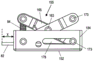
Fig. 38A and 38B illustrate a simple four-bar mechanism in raised and lowered positions, respectively, that can be used to register the trigger force and displace the shaft.
Fig. 39A, 39B and 39C each illustrate a scissor mechanism without a position restoring element (39A), with a tension spring (39B) as a position restoring element, and a compression spring (39C) as a position restoring element, respectively.
Fig. 45 is an isometric view of a tactile feedback mechanism.
Fig. 46A-46F illustrate various views of the components and operation of the mechanism of fig. 45.
Fig. 47 and 48 illustrate side views of a tool-carried tracking device mounted on a surgical instrument having a tool (here, a saw) with the tactile feedback mechanism of fig. 45 in place to interact with a trigger of the surgical instrument. Fig. 47 illustrates the tactile feedback mechanism in an expanded configuration covering the trigger, and fig. 48 shows the tactile feedback mechanism collapsed to expose the trigger.
49A-49B illustrate another alternative of a tactile feedback mechanism in an open or expanded state (FIG. 49A) and a closed state (FIG. 49B).
Fig. 49C-49E illustrate various views of the internal mechanism of the device in fig. 49A and 49B.
Fig. 50 illustrates an embodiment of an OTT coupled for use with a surgical tool having an embodiment of the mechanism of fig. 49A and 49B mounted for cooperation with a trigger of the surgical tool and configured to send and receive triggers related to components in the OTT.
FIG. 51 is a cross-sectional view of an alternative embodiment of a scissor mechanism utilizing two position restoration members.
Fig. 52A and 52B are front and rear isometric views, respectively, of a tool-borne tracking and guidance device (OTT) including a display having an OTT housing coupled to a surgical tool having a trigger-based feedback mechanism coupled to the OTT. This view also shows an exemplary computer system in communication with the OTT.
Detailed Description
The present invention is a system for performing computer-assisted orthopaedic surgery and a novel tool for operating the system. The present invention overcomes the limitations of current computer assisted surgery systems by optionally incorporating all of the elements of computer assisted surgery (tools, displays and tracking) into a single smart instrument. The instrument does not rely on an external guidance system, but the tool contains all the tracking devices in a self-contained assembly on the tool itself. Thus, the overall system is significantly less complex, less invasive to the surgeon and easy to incorporate into existing practice of orthopedic surgery.
In an overview manner, the system consists of major subsystems. First is the tool itself, which is used to carry a separate on-tool tracking device or is modified to include a subsystem or elements of a subsystem, thereby providing on-tool tracking (OTT) functionality. The modifications can be simple, such as expanding the chassis to hold additional components, or complex, such as modifying the power system to power additional subsystems and/or stop or control motor speeds or other actuators on the powered tool. The second subsystem is a tracking subsystem that includes one or more trackers and one or more tracking elements. The tracker can be one or more cameras (stereo viewers) sensitive to visible light or light from another wavelength. Alternatively, the tracker may be an electromagnetic tracker or other non-camera based system. A tracking element is any object that the tracker tracks. For example, where the tracker is an infrared camera, the tracking element is an infrared LED, or a passive surface that reflects infrared light emitted from around the camera or other locations. Where the tracker is a pair of high resolution cameras sensitive to visible light, the tracking element may be a specific anatomy of the patient or a marker made directly on the anatomy including the marker or frame of reference. The subsystem is capable of tracking one or more tracking elements with one or more trackers mounted on the tool in various configurations. In one aspect, a tracker that tracks tools, patients, and other related targets using desired sensors to perform OTT CAS surgery is positioned at least partially in a self-contained manner on a surgical tool. The guidance system guides when the tracking subsystem calculates the position of the tracking element relative to the tool.
The third subsystem is an OTT CAS computer system that contains the appropriate CAS planning software and programs to perform OTT CAS functional surgical planning. The surgical plan can be generated in a variety of ways, but contains the dimensions of the resection (e.g., incision, bore, volume of tissue to be removed) in three-dimensional space as intended by the operator. The system can also contain a reference image of the patient anatomy, such as a computed tomography image (dataset) of the patient anatomy, and a 2D or 3D virtual model of the patient anatomy as a reference point. The computer system compiles data from the tracking system and the surgical plan to calculate the relative position of the boundary of the resection intended by the tool definition. In some configurations, the computer system can be a completely separate component that communicates wirelessly with other components. In other configurations, the computer system is integrated into other systems. The tracking system and computer system together are able to determine if the surgeon's position and the motion of the tool (surgical path) will produce the desired resection. It is important to note that the computer subsystem and the tracking subsystem work together to establish a three-dimensional space of the surgical site. The elements required for the tracking subsystem to function can be located in the computer subsystem or some intermediate mode of transmitting tracking data to the computer subsystem.
The last subsystem is an indicator to provide the surgeon with the OTT CAS appropriate output related to the surgeon's movement of the tool and the relationship intended to be resected in the real-time OTT CAS step. The indicator can be any type of way of aligning/positioning the surgical path with the intended resection: a set of lights on the OTT-equipped tool to correct the surgeon, a speaker with audible indication, a screen, a touch screen, or an iPhone or iPAd-like device (i.e., a so-called "smartphone"), displays a three-dimensional representation of the tool and patient, with an added guide image or digital projection (e.g., by a pico-projector) on the patient anatomy in the appropriate location for ablation. The indicator is used to provide the appropriate OTT CAS output to guide the surgeon in making the correct resection based on real-time information.
Turning now to the specific subsystems:
a surgical suite for computer-assisted surgery includes a first computer for preoperative use. For example, pre-operative analysis of the patient and selection of various components may be performed on the first computer. The surgical suite may also include a second computer, referred to as an OR computer, that is used during the surgical procedure to assist the surgeon and/OR control one OR more surgical instruments. Additionally, the surgical suite may include a computer (either separate or in cooperation with another computer) mounted on the surgical instrument via an embodiment of the on-tool tracking system. The first computer is provided in this example, but may be omitted in some configurations, as the functions of this computer are also performed on the OR computer, which can be independent. Furthermore, the entire 'pre-operative plan' may ultimately occur instantaneously within the OR, primarily using an OR computer in conjunction with OTT. However, the first computer may be used if desired for a particular application. Preoperative planning and surgery can also be aided by data from an online network link or active guidance. As used herein, the term CAS system or CAS computer refers to computers or electronic components such as those provided in any of these combinations that perform a CAS function. Furthermore, the microprocessor unit of the system can be located in the on-tool tracking instrument. In such a configuration, the calculations and user interaction can be performed within a computer carried on the surgical tool being used or in cooperation with a host system computer through wired or wireless communication. In cooperation with the main OTT CAS computer through wireless communication, such a system performs an error analysis of the position of the cutting instrument relative to the ideal cut to be performed, and for this purpose, either alone or in any combination with the output provided by the OTT-equipped projector or projectors, displays the correct motion and other information on a screen provided as part of the on-tool tracker.
Thus, a surgical suite for OTT CAS may include a tracking/guidance system that allows for real-time tracking of the position in space of several elements, including: (a) structures of the patient, such as bone or other tissue; (b) surgical tools, such as bone saws and/OR OTTs, which carry the OTT and are controlled by the surgeon based on information from the OR computer OR (c) surgeon/assistant system specific tools, such as pointers, registration tools OR other objects if needed. The OR computer OR OTT may also perform some control over the instrument. Based on the position of the tool and feedback from the OTT, the system or CAS computer can change the speed of the surgical tool as well as shut down the tool to prevent potential damage. Additionally, the CAS computer may provide variable feedback to the user. The surgical instrument shown in the accompanying description is a surgical saw. It will be appreciated that many other instruments can be controlled and/or guided as described herein, such as drills, grindstones, rasps, broaches, scalpels, needles, or other instruments. Thus, in the following discussion, the OTT-enabled CAS system is not limited to the specific tools described, but is applicable to a variety of instruments and procedures.
As discussed further below, one exemplary use of a surgical suite includes the use of a virtual model of a portion of a patient on which a procedure is to be performed. Specifically, prior to surgery, a three-dimensional model of the relevant portion of the patient is generated using a CT scan, MRI scan, or other technique. Prior to surgery, the surgeon may view and manipulate the patient model to evaluate the strategy for performing the actual surgery.
One possible approach is to use the patient model as a guide during the procedure. For example, prior to surgery, a surgeon may analyze a virtual model of a portion of a patient and mark on the map the tissue to be resected during the surgery. The model is then used to guide the surgeon during the actual surgery. In particular, during the procedure, a tracking device carried by the tool monitors the progress of the procedure. As a result of the OTT CAS procedure being performed, the procedure/results are displayed in real time on an OR computer OR OTT monitor (e.g., on an LCD-loaded screen) so that the surgeon can see the procedure relative to the patient model. Importantly, the surgeon also provides an OTT projector to provide real-world feedback based on OTT CAS processing steps (described in more detail below).
To provide guidance assistance during OTT CAS procedures, a tool-borne tracking device monitors the position of an associated surgical tool within a surgical field. The OTT CAS system may not use or use one or more reference frames that include one or more position sensors or one or more fiducial markers depending on the requirements of the OTT CAS procedure undertaken. Any of the above-described markers may be utilized in active or passive configurations. The marker may optionally be a wired or wireless sensor in communication with the system. The active tag transmits a signal that is received by the OTT device. In some configurations, the passive tags are wireless tags that do not have to be electrically connected to the OTT CAS system. Typically, passive markers reflect infrared light back to the appropriate sensor on the OTT device. When passive markers are used, the surgical field under observation is exposed to infrared light, which is then reflected back to and received by the OTT, whereby the OTT CAS determines the data location of the passive marker. Some embodiments of OTT devices may be provided with an infrared transmitting device and an infrared receiver. The OTT receives the emitted light from the active markers and the reflected light from the passive markers, along with other visual area information from the OTT. The OTT CAS system calculates and triangulates the three-dimensional position of the tool based on visual processing of the image including the location of the markers along with other image information in the surgical field. Embodiments of the on-tool tracking device are operable to detect the orientation of the OTT-enabled tool relative to three orthogonal axes. In this way, using information from the OTT device, the OTT CAS system determines the position and orientation of the tool, and then uses this information to determine the OTT CAS processing mode and generate the appropriate OTT CAS output for the user.
As is typical in CAS, a series of points or surfaces are used to register or correlate the position of the patient's anatomy with the virtual model of the patient. To gather this information, a guided pointer is used to acquire a point at an anatomical landmark or a set of points on a surface within the patient's anatomy. A process known as deformation may alternatively be used to register a patient to an approximate virtual model of that patient that is taken from an atlas or database and that is not derived from actual images of the particular patient. In this procedure, the surgeon digitizes portions of the patient and some strategic anatomical landmarks. The OTT CAS computer analyzes the data and identifies common anatomical features to thereby identify the location of points on the patient that correspond to particular points on the virtual model.
Accordingly, as mentioned above, the on-tool tracking device visually monitors the position of several objects in real time, including: the position of the associated surgical tool, the position of the patient, and the position of an object (such as one or more frames of reference or one or more markers) used during the procedure. Accordingly, the OTT CAS computer processes OTT CAS data regarding the location of the associated surgical tool, visual zone information in the OTT image data, data regarding the location of the patient, and data regarding the model of the patient. This result of the OTT CAS computer processing provides dynamic, real-time interaction position and orientation feedback information that can be viewed by the surgeon on a monitor provided by the OTT device (if provided) or as a display output of the OTT projector. Further still, as previously described, prior to surgery, the surgeon may analyze the patient model and identify the tissue to be resected and plan or indicate the desired OTT CAS mode to be used during the OTT CAS procedure or during the CAS procedure. This information can then be used during the surgical procedure to guide the surgeon using dynamically adjusted outputs based on the mode of CAS processing and other factors.
Fig. 1 is an isometric view of an on-tool tracking device (OTT)100 configured to track and provide guidance during computer-assisted surgery using a surgical instrument 50. OTT 100 has a housing 105 that includes a pair of cameras 115 in an opening for a projector output 110. OTT 100, and also as housing 105, has a surface 120 adapted and configured to mate with surgical instrument 50. The surgical instrument 50 includes a trigger 52 for operating a tool 54 having a movable element 56. In the exemplary embodiment of fig. 1, the tool 54 is a saw and the movable element 56 is a serrated edge of its distal end.
Fig. 2 is an isometric view of an on-tool tracking device (OTT)200 configured to track and provide guidance during computer-assisted surgery using the surgical instrument 50. OTT 200 has a housing 205 that includes a pair of cameras 215 in an opening for a projector output 210. OTT 200, and also as housing 205, has a surface 220 adapted and configured to mate with surgical instrument 50. The surgical instrument 50 includes a trigger 52 for operating a tool 54 having a movable element 56. In the exemplary embodiment of fig. 2, the tool 54 is a saw and the movable element 56 is a serrated edge of its distal end.
Fig. 3 and 4 are isometric views of the on tool tracking device of fig. 1 and 2 with the top cover of the housing removed. In the view of fig. 3, the exposed interior of the housing 105 shows the arrangement of the processing circuitry 130, projector 125, and camera 115. The output 110 of the projector 125 is illustrated in this embodiment as being in a position above a plane containing the camera 115. In the view of fig. 4, the exposed interior of the housing 205 shows the arrangement of the processing circuitry 230, the projector 225, and the camera 215. The output 210 of the projector 225 is illustrated in this embodiment as being at a position that is above and at an acute angle to the plane containing the camera 215.
Figures 5, 6 and 7 show a top view and two isometric views of the on tool tracker 200. In the top view of the tool-borne tracker shown in fig. 4, the orientation and placement of the electronic components is clearly visible. Due to the type of projector 225 used in this configuration, the projector has been positioned angularly within the housing 205, as shown in FIG. 6, on a slightly inclined surface. In one embodiment, one or both of the camera or projector of the on-tool tracking device may be positioned in any orientation and then the orientation compensated for the results of the operation of the respective device in other ways as described herein. In this manner, a variety of different OTT electronic component designs are possible since slight physical misalignments may be accommodated using software techniques as described herein. Fig. 7 illustrates an isometric view of the electronics of the tool-carried tracker 200 separated from the housing 205. The figure illustrates one embodiment of a referenced one-piece "OTT electronics package for arrangement within the housing 205 on a single board 235 with the camera 215, projector 225, and associated processing electronics 230.
Fig. 8A, 8B, 9, and 10 all illustrate the results on the camera viewing area for various camera angle orientations of the camera included within the on-tool tracking device. The cameras 115 in fig. 8A are oriented in a near parallel arrangement with respect to each other and the axis of the surgical tool 54. This configuration provides a camera viewing area ranging from about 70mm to about 200mm after accounting for occlusions caused by other components. In other embodiments, the camera system of the exemplary OTT device may operate in a camera viewing area ranging from about 50mm to about 250 mm. It will be appreciated that the camera viewing area may be physically or electronically altered depending on the desired viewing area required for the particular computer-assisted surgery that the OTT device will be used to perform.
In contrast to the near parallel arrangement of cameras in fig. 8A, fig. 8B, 9, and 10 each show the results of different camera tilt angles and the resulting change in the camera viewing area. The relationship of OTT camera positioning and tilt angle, and its relationship to viewing angle, minimum target distance, and maximum target length, is better understood with reference to fig. 11A, 11B, 11C, and 11D. FIG. 11A illustrates geometric settings and formulas that make calculations to produce the graph of FIG. 11B that relates tilt angle in degrees to a number of visual area factors. The tilt angle-related data from the graph is reproduced in the graphs shown in fig. 11C and 11D. The optical zone information presented in these figures is useful in the design and optimization of camera positioning in some of the various embodiments of OTT devices described herein.
Additional aspects of the projector for various OTT implementations may be understood with reference to fig. 12A, 12B, 13A, 13B, and 13C. A comparison between fig. 12A and 12B shows the effect on projector output based on the positioning of the projector within the OTT enclosure. As shown in fig. 12A and 13A, the projector 125 appears to be in a near planar relationship with respect to the tool 54. Note, however, how a portion of projector output 126 extends beyond tool distal end 56 and below tool distal end 56. In contrast, projector 225 is positioned at an acute angle with respect to tool 54. Additionally, the projector output to 10 is skewed to one side when compared to its relative position between cameras 215. However, the projector output 226 passes primarily over the blade 54 and only at the distal end 56. Additional aspects of the projector output to 26 will be apparent upon review of the views in fig. 13B and 13B. It is understood that the projector output, projector size and orientation described in these embodiments are not limited to all OTT device embodiments. Suitable OTT projectors may be constructed in a number of satisfactory ways and the arrangement within the OTT enclosure may be adjusted based on the desired packaging size of the projector. As clearly illustrated by the sampled output of projector 225, many different projector sizes, orientations, and angular relationships can be used and still operate effectively to meet the projector requirements of the OTT CAS processing system. In other words, a wide variety of projector types, output locations, and packaging may be used and still remain within the various embodiments of OTT devices described herein.
Embodiments of the OTT device of the present invention are provided with various images, projectors and electronics depending on the specific operational characteristics desired for a particular OTT CAS system. The following illustrative embodiments are provided in order to understand a wide variety of features and design factors for this portion of the OTT CAS system.
Figure 14A illustrates a schematic diagram of an embodiment of an OTT device. In the illustrated embodiment, there is provided
Camera/digital Signal processor/processing NaturalPoint Optitrak SL-V120 Range
Computer: PC-Windows 2000/XP/Vista/7; a 1.5GHz processor; 256MB of RAM; 5MB of available hard disk space; USB 2.0 high speed port (min, faster and better)
COM: DYNADOCK W20 port replicator with wireless USB support;
projector: micro vision's SHOWX laser microprojector
As shown in the view, it is disposed within the OTT enclosure. This embodiment uses a so-called "smart camera", i.e. a camera with the capability of performing local image processing. The process can be programmed, typically by a Field Programmable Gate Array (FPGA). The configuration of the components in this particular embodiment are utilized to provide image processing that occurs on OTT devices and on OTT CAS computers. For example, a DSP on the OTT device detects and processes the tagged data before transmitting it to the OTT CAS computer. This configuration greatly reduces the processing power required on the host while also minimizing the data that needs to be transmitted. It will be appreciated that the schematic view, while primarily intended to display the type of image, data processing between a particular OTT device or OTT device and OTT CAS computer, and overall computer processing capabilities, may not reflect the actual orientation, spacing, and/or alignment between particular components. Electronic communication Capabilities (COM) are provided via a wired connection or any suitable wireless data transfer mode from and to a computer adapted and configured for OTT CAS processing, algorithms and modes described herein. The type, diversity, quantity, and quality of the process data exchange between the OTT device and the OTT CAS computer (if used) will vary depending on the specific parameters and considerations of the particular OTT CAS program, mode or system utilized.
Figure 14B illustrates a schematic diagram of an embodiment of an OTT device. In the illustrated embodiment, there is provided
A camera: a wired or wireless analog camera; such as FPV wireless camera
DSP: and the uCFG singlechip is used for grabbing the frame device. Which is connected to the PC PCI bus and becomes part of the PC.
Computer: PC-Windows 2000/XP/Vista/7; a 1.5GHz processor; 256MB of RAM; 5MB of available hard disk space; USB 2.0 high speed port (min, faster and better)
COM: hard-wired or analog radio transmitter
Projector: micro vision's SHOWX laser microprojector
As shown in the view, it is disposed within the OTT enclosure. The configuration of components in this embodiment is utilized to provide for the use of a low cost commodity camera in which image processing for tracking is not performed on the OTT and the image signal is captured by a dedicated frame grabber that is part of the PC. The frame grabber receives the captured image and stores it in the PC memory without any overhead processing by the PC. This embodiment results in a smaller, lighter and less costly OTT device.
It will be appreciated that the schematic view, while primarily intended to display the type of image, data processing between a particular OTT device or OTT device and OTT CAS computer, and overall computer processing capabilities, may not reflect the actual orientation, spacing, and/or alignment between particular components. Electronic communication Capabilities (COM) are provided via a wired connection or any suitable wireless data transfer mode from and to a computer adapted and configured for OTT CAS processing, algorithms and modes described herein. The type, diversity, quantity, and quality of the process data exchange between the OTT device and the OTT CAS computer (if used) will vary depending on the specific parameters and considerations of the particular OTT CAS program, mode or system utilized.
Figure 15A illustrates a schematic diagram of an embodiment of an OTT device. This embodiment utilizes a commercial USB camera with incorporated electronic circuitry that captures the image from the camera and adjusts it to be USB compatible. The output is compressed and then transmitted, either wired or wirelessly, without further processing related to tracking.
In the illustrated embodiment, there is provided
A camera: microsoft Lifecam
Computer: dell precision R5500 work station
COM: carbobola 8 device core, or DTW-200D (CDMA 20001X) and DTW-500D (EVDO Rev A)
Projector: micro vision's SHOWX laser microprojector
Which are arranged as shown in the drawings. The configuration of the components in this embodiment is utilized to provide a modular solution for providing electronic OTT components. This embodiment uses low cost commodity cameras and allows the cameras to be used in a modular fashion where they can be changed or upgraded to reflect technological advances and without disrupting OTT or terrestrial systems.
If the OTT CAS computer is optimized for DSP, there is no need to use a tool-borne DSP. This embodiment makes it possible to use any of the commercially available image processing libraries. For example, Halcon image processing software only requires about 1ms to process a very large block of binary data (bone reference frame LED) and calculate its centroid. Thus, images can be sent directly from the OTT tool to the OTT CAS computer for processing. Importantly, COM will need to be selected to handle higher bandwidth when compared to other implementations. Similarly, the computer would need to be selected to handle more heavy calculations.
It will be appreciated that the schematic view, while primarily intended to display the type of image, data processing between a particular OTT device or OTT device and OTT CAS computer, and overall computer processing capabilities, may not reflect the actual orientation, spacing, and/or alignment between particular components. Electronic communication Capabilities (COM) are provided via a wired connection or any suitable wireless data transfer mode from and to a computer adapted and configured for OTT CAS processing, algorithms and modes described herein. The type, diversity, quantity, and quality of the process data exchange between the OTT device and the OTT CAS computer (if used) will vary depending on the specific parameters and considerations of the particular OTT CAS program, mode or system utilized.
Figure 15B illustrates a schematic diagram of an embodiment of an OTT device. In the illustrated embodiment, there is provided
A camera: a smart camera as in fig. 15A or a USB camera as in fig. 15B
An inertial sensor: bosch SMB380, Freescale PMMA7660, Kionix KXSD9
On-board processors: ARM processor
Computer: PC-Windows 2000/XP/Vista/7; a 1.5GHz processor; 256MB of RAM; 5MB of available hard disk space; USB 2.0 or USB 3.0 high speed port (smallest, faster or better)
COM: standard IEEE 802.11 communication protocol or similar protocol for communication between a processor bearing OTT and a ground station PC
Projector: micro vision's SHOWX laser microprojector
Which are arranged as shown in the drawings. The configuration of the components in this embodiment are utilized to provide an embodiment that performs complex processes on the OTT device to accomplish most body tracking as needed for the purposes of OTT CAS procedures. The device is a completely self-contained tracking device. OTT devices also contain one or more inertial sensors. DSP involves the use of inertial sensors to predict the position of the reference in the 'next frame'. Thus, the computational burden on the DSP on the OTT device is minimized.
It will be appreciated that the schematic view, while primarily intended to display the type of image, data processing between a particular OTT device or OTT device and OTT CAS computer, and overall computer processing capabilities, may not reflect the actual orientation, spacing, and/or alignment between particular components. Electronic communication Capabilities (COM) are provided via a wired connection or any suitable wireless data transfer mode from and to a computer adapted and configured for OTT CAS processing, algorithms and modes described herein. The type, diversity, quantity, and quality of the process data exchange between the OTT device and the OTT CAS computer (if used) will vary depending on the specific parameters and considerations of the particular OTT CAS program, mode or system utilized.
In addition to the details and detailed description above, it will be appreciated that alternative embodiments of OTT devices may have electronic components including components with processing capabilities and software and hardware and electronic instructions to provide one or more of the following exemplary types of OTT CAS data according to the OTT CAS processing methods, modes and algorithms described herein:
receiving and processing visual and IR spectral image data
Determining the coordinates of the centroid of each marker within the image frame
Determining the size of all markers within an image frame
Reporting the dimensions and coordinates of one or more references
Sub-pixel analysis to determine the location of a centroid, marker arrangement or selected marker arrangement within an image frame
Adapting a variable and controllable frame rate from 20 to 60 frames per second based on input from a central computer or internal instructions or in response to an OTT CAS processing mode
Fig. 16A, 16B, and 16C provide various views of a reference frame 300 used in computer-assisted surgery. A frame 305 is provided having a surface 310 defined by a perimeter 315. One or more active or passive fiducial marks 70 are arranged in a pattern 72 across the surface 310. There is a rod 320 extending from the frame 305 and a coupling 325 on the rod. The coupling 325 is used to couple the frame 305 to the base 330. The base 330 has a first surface 335 configured to engage a portion of an anatomical structure within a surgical field associated with a procedure. Base 330 has a second surface 340 to engage with coupling member 325. Coupling 325 and second surface 340 are engaged in fig. 16A, but are disengaged in fig. 16B and 16C. In the views of fig. 16C and 16C, at least one registration element is visible on the link and at least one registration element is visible on the second surface. In the illustrated embodiment, registration element 342b is a female feature on coupling 325, and coupling element 325a on second surface 340 is a male feature. The registration elements are sized and positioned to cooperatively cooperate when the link 325 and the second surface 340 are engaged. It will be appreciated that a variety of different registration element types and locations may be adapted and configured for providing mating cooperation when the link is joined to the second surface.
The base 330 includes a second surface 335 to engage the anatomical structure. All or a portion of the surfaces may include serrated edges to aid in engagement with anatomy, particularly bony anatomy surrounding a joint. The base first surface 335 includes a curvature that is complementary to the anatomical site to which the base first surface is attached during the surgical procedure. In one embodiment, a bony portion of the anatomy is adjacent to a joint targeted for surgery. The joint may be selected from knee, shoulder, wrist, ankle, hip or vertebra. The base 330 includes at least one aperture 337, the at least one aperture 337 being adapted and configured for a fixation element to affix the base to a site on a human body. The fixation element may be selected from one or more of a pin, screw, nail, or surgical staple.
Fig. 17 illustrates a schematic view of the reference frame guide 350. The reference frame guide 350 has a frame 355 and a rod 360 extending from the frame 355. The rod 360 has a curvature or shape configured to engage an anatomical feature to assist in arranging the reference frame 300 in a desired position and orientation within a surgical field when the frame guide is attached to the frame 305. The reference frame guide 350 also includes one or more engagement elements 365 along the frame 355 for temporarily engaging the perimeter 315 or a portion of the reference frame 305 to allow proper positioning and adjustment of the base 330 associated with the reference frame 300 attached using the elements 365. Fig. 18 illustrates a reference frame guide attached to the frame 305 of the reference frame 300. In use, engagement element 365 can be broken to remove the reference frame from the guide frame during a surgical procedure. Although illustrated as cooperatively cooperating with reference frame 300, reference frame guide 350 may be adapted and configured to form a cooperative engagement with reference frames of different shapes and sizes, such as reference frame 400 in fig. 24.
In a particular embodiment, the curvature or shape 362 of the rod 360 is configured for placement of the rod with respect to the condyle to provide alignment of the frame of reference 300 along the femur within the surgical field. Fig. 19 and 20 illustrate the positioning of the base 330 along the femur 10. The articular reference frame guide and reference frame structure (see fig. 18) are positioned (along the arrows in fig. 19) such that the curvature 362 of the rod 360 is aligned between the condyles 12 of the femur 10, thereby placing the base 330 on the femur in the proper orientation as shown in fig. 20. Thereafter, reference frame 300 is attached to femur 10 by joining base first surface 335 with one or more methods, such as application of screws or nails to apertures 337 or use of biocompatible bone cement. Once the reference frame 300 is confirmed in position, the reference frame guide 350 is removed (fig. 21), leaving only the reference frame in the desired relationship with the condyle 12 and in the desired position along the femur 10 according to the surgical plan to be performed (fig. 22).
Fig. 23 illustrates an embodiment of a reference frame 400 and a location along tibia 15. In the illustrated embodiment, reference frame 400 is attached to or surrounds the tibial tuberosity (shown more clearly in fig. 25) and is secured to the bone using any of the several fixation methods described above with respect to reference frame 300. Additional details of reference frame 400 may be provided after reading fig. 24A, 24B, and 24C. These figures provide various views of a frame of reference 400 used in computer-assisted surgery. A frame 405 is provided having a surface 410 defined by a perimeter 415. One or more active or passive fiducial marks 70 are arranged in a pattern 74 across the surface 410. There is a rod 420 extending from the frame 405 and a link 425 on the rod. The link 425 serves to join the frame 405 to the base 430. The base 430 has a first surface 435 configured to engage a portion of an anatomical structure within a surgical field associated with a procedure. The base 430 has a second surface 440 to engage the link 425. The link 425 and the second surface 440 are engaged in fig. 24A, but are disengaged in fig. 24B and 24C. In the views of fig. 24C and 24C, at least one registration element is visible on the link and at least one registration element is visible on the second surface. In the illustrated embodiment, registration element 442b is a female feature on link 425, and link element 425a on second surface 440 is a male feature. The registration elements are sized and positioned to cooperatively cooperate when the link 425 and the second surface 440 are engaged. It will be appreciated that a variety of different registration element types and locations may be adapted and configured for providing mating cooperation when the link is joined to the second surface.
The base 430 includes a second surface 435 to engage the anatomical structure. All or a portion of the surfaces may include serrated edges to aid in engagement with anatomy, particularly bony anatomy surrounding a joint. The base first surface 435 includes a curvature that is complementary to the anatomical site to which the base first surface is attached during the surgical procedure. In one embodiment, a bony portion of the anatomy is adjacent to a joint targeted for surgery. The joint may be selected from knee, shoulder, wrist, ankle, hip or vertebra. The base 430 includes at least one aperture 437, the at least one aperture 437 adapted and configured for a fixation element to affix the base to a site on a human body. The fixation element may be selected from one or more of a pin, screw, nail, or surgical staple.
Turning now to fig. 26A, 26B, and 26C, additional aspects of the designed reference frame are described. Referring to fig. 26A, the orientation between the frame 305 and the base 300 can be adjusted between a variety of preset orientations. Changing the relationship between the two components is accomplished by changing which of the registration elements available to the joint are the engagement components. In one aspect, a plurality of registration elements are provided on the link and a plurality of registration elements are provided on the second surface. The orientation of the frame of reference can be adjusted between a first orientation 382 and a different second orientation 384, based on which the registration element groupings are used to join the base 330 to the frame 305. In one embodiment, wherein a portion of the registration element on the link engages a portion of the registration element on the second surface, the frame is oriented in a first orientation within the surgical field as a result. On the other hand, a different registration element on the link mates with a different registration element on the second surface, with the result that the frame 305 will be presented in a different second orientation within the surgical field. In one aspect, the first orientation is a known position used in surgical preplanning. The second orientation, on the other hand, is a known position used in surgical preplanning. The first orientation and/or the second orientation may be used in furtherance of the OTT CAS techniques described herein.
Fig. 26A also illustrates one embodiment of a mounting coupler adapted and configured to maintain the relative position and orientation of the coupler and the second surface. In this embodiment, a flexible coupling mechanism is shown between these two components, and its size, shape and orientation within the reference frame serves to maintain the orientation of the frame 305 within the surgical field. In other words, the mounting coupler is sufficiently rigid that it does not lose its alignment if frame 305 is impacted during a procedure. In another alternative aspect, the mounting link is disposed entirely in the structure in use, the mounting link being disposed such that when the mounting link is attached to the reference frame, the mounting link substantially or entirely surrounds an area of mating contact between the link and the second surface.
Fig. 27A and 27B provide alternative reference frame surface shapes and alternatives to display the marking pattern. FIG. 27A illustrates a generally rectangular frame 390 of a reference frame having a plurality of fiducial markers 70 arranged in a pattern 78. Figure 27B illustrates a generally trapezoidal surface shape 310 on a frame 395. A plurality of fiducial marks 70 are disposed in a pattern on the surface 305.
Figure 28 illustrates an isometric view of a representation of the prosthesis 20 used in a total knee replacement procedure. The numbers marked on the prosthesis 20 are representative of the type of incision made during knee surgery. 29A-29I and 30 illustrate one of the unique combinations of the OTT CAS systems described herein. Although each of the above-described reference frames may be used independently or in conjunction with other anatomical sites or surgical devices, the reference frames 300 and 400 have particular advantages for the on-tool tracking device and OTT CAS procedures described herein. One challenge in using on-tool tracking devices for hand-held pre-cut surgery is obtaining relevant tracking information and maintaining a tracked frame of reference during the procedure. With a unique design and arrangement, the reference frames 300 and 400 can be used to provide just this type of dynamic reference frame tracking using the OTT tracking techniques described herein. As shown in the following figures, in each of the representative incisions used to implant the prosthesis 20, the vision system carried on the OTT 100 can be visually identified and registered with all or a portion of the reference frames 300 and 400. Although these particular configurations are illustrative of the capabilities of OTT CAS systems and tools for knee surgery, it will be appreciated that the reference frame and visual guidance techniques described herein may be adapted for other joints and other procedures in the human body.
Fig. 29A-29I and 30 each illustrate a representative surgical setup for placement of reference frame 300 on femur 10 and placement of reference frame 400 along tibia 15, particularly on tibial tuberosity 18 or around tibial tuberosity 18. It will be appreciated that the OTT CAS procedures illustrated subsequently utilize reference frames 300, 400 that do not move during all subsequent OTT CAS process steps, but remain in the same position. The on-tool tracking device 100 is coupled to the surgical tool 50 for positioning and use of the tool 54 with the movable element 56.
In the illustrative embodiment of fig. 29A, OTT 100 provides a guide for making a distal lateral condyle cut using active element 56. In this cutting process, the camera carried on OTT 100 captures, images and provides relative guidance and positioning information based on information received from reference frame 300 and reference frame 400 during all or a substantial portion of the illustrated cutting.
In the illustrative embodiment of fig. 29B, OTT 100 provides a guide for making a distal medial condyle incision using active element 56. In this cutting process, the camera carried on OTT 100 captures, images and provides relative guidance and positioning information based on information received from reference frame 300 and reference frame 400 during all or a substantial portion of the illustrated cutting.
In the illustrative embodiment of fig. 29C, OTT 100 provides a guide for making an anterior incision using active element 56. In this cutting process, the camera carried on OTT 100 captures, images and provides relative guidance and positioning information based on information received from reference frame 300 and reference frame 400 during all or a substantial portion of the illustrated cutting.
In the illustrative embodiment of fig. 29D, OTT 100 provides a guide for making a posterior lateral condyle cut using mobile element 56. In this cutting process, the camera carried on OTT 100 captures, images and provides relative guidance and positioning information based on information received from reference frame 300 and reference frame 400 during all or a substantial portion of the illustrated cutting.
In the illustrative embodiment of fig. 29E, OTT 100 provides a guide for making a posterior medial condyle incision using mobile element 56. In this cutting process, the camera carried on OTT 100 captures, images and provides relative guidance and positioning information based on information received from reference frame 300 and reference frame 400 during all or a substantial portion of the illustrated cutting.
In the exemplary embodiment of fig. 29F, OTT 100 provides a guide for making a front chamfer cut using movable element 56. In this cutting process, the camera carried on OTT 100 captures, images and provides relative guidance and positioning information based on information received from reference frame 300 and reference frame 400 during all or a substantial portion of the illustrated cutting.
In the illustrative embodiment of fig. 29G, OTT 100 provides a guide for making a posterior lateral condyle chamfer cut using mobile element 56. In this cutting process, the camera carried on OTT 100 captures, images and provides relative guidance and positioning information based on information received from reference frame 300 and reference frame 400 during all or a substantial portion of the illustrated cutting.
In the illustrative embodiment of fig. 29H, OTT 100 provides a guide for making a posterior medial condyle chamfer cut using mobile element 56. In this cutting process, the camera carried on OTT 100 captures, images and provides relative guidance and positioning information based on information received from reference frame 300 and reference frame 400 during all or a substantial portion of the illustrated cutting.
In the illustrative embodiment of fig. 29I, OTT 100 provides a guide for making a tibial cut using mobile element 56. In this cutting process, the camera carried on OTT 100 captures, images and provides relative guidance and positioning information based on information received from reference frame 300 and reference frame 400 during all or a substantial portion of the illustrated cutting.
FIG. 30 illustrates an OTT 100 coupled to a surgical instrument 50 having a tool 54 and a movable element 56. Reference frames 300, 400 are also shown with respect to OTT CAS surgical sites surrounding the knee. An additional reference frame 397 with rods 398 and ends 399 is used for further registration or marking of the surgical field. Registration of the frame of reference 397 is provided by the imaging system of the OTT 100 with the tool. Registration frame 397 registers along with registration frame 300 and/or registration frame 400. Although the embodiments of the OTT CAS method described herein utilize reference frames 300 and 400, it will be appreciated that the OTT CAS system has two available reference frames due to the improved image-based tracking capabilities of the OTT and OTT CAS processes, but chooses to use tracking information from only one reference frame during the process.
When considering the use of the unique reference frame embodiments described herein, it is contemplated that OTT CAS system users prefer the manner in which they can view. The OTT CAS system is preprogrammed such that for some incisions, some observations are shown by default. For example, in the case of resecting a femur in preparing a femoral prosthesis for TKR surgery, several surfaces are to be resected, as shown in fig. 29 and 30. Each surface can be optimally viewed from a different angle during the procedure. A first view may be desired when cutting the anterior surface of the medial condyle and a second view may be desired when cutting the anterior surface of the lateral condyle. Accordingly, the system sets a predetermined first view for viewing the virtual model as the anterior surface of the medial condyle is resected. Similarly, a default visual observation can be defined for multiple common resection procedures. When the OTT CAS system determines that a cut is to be performed, the system determines the best match for the cut and automatically displays the default without surgeon intervention. In much the same way, a vision-based process performed by the OTT CAS computer can be pre-selected to automatically use all or a portion of the available tracking information from one or both frames of reference depending on the circumstances. In addition, the OTT CAS may guide the user to adjust the orientation of the frame of reference within the surgical field to improve guidance from the frame. Although adjustable orientations of the frame that maintain the registered position of the base are described herein.
It is understood that any of a wide variety of power or non-power tools can be utilized with the OTT CAS system described herein. For example, in the field of orthopedics, the system can be built on a single orthopedic powered saw (such as a Stryker system 6 precision vibrating saw). Similarly, the system can be used with other power tools commonly used in orthopedics, such as a sharpening stone or a drill. In such applications, the system may be integrated within the design of the surgical tool or added as a retrofit. Additionally, the system may utilize tools that do not require any external power source (such as a pointer, marker, or scalpel). Ideally, the system can accommodate multiple intelligent tools to be used at different stages of a surgical procedure and make the system robust enough to perform a wide variety of surgical procedures.
The system may be used in applications other than orthopedic surgery. For example, it may be used in simulations and simulators for guiding and training orthopaedic surgeons. Alternatively, the system may be used for other medical procedures that require precise orientation and manipulation of hard tissue. Computer assisted surgery of the present technology can readily facilitate such dental procedures. The system can also be used in non-medical applications, for example, in woodworking, sheet metal processing, and all other engineering marking and processing processes to guide a user in making a particular pattern of material cuts or bores.
Embodiments of the OTT CAS system described herein eliminate the need for an external tracking device by placing one or more trackers on the tool. The present invention can eliminate the need for an external tracking system altogether or utilize the tracking subsystem to add new tracking data. In either configuration, the tool itself tracks the anatomy of the patient, or tracks itself relative to the patient anatomy, as opposed to an external tracker that tracks both the tool and the patient anatomy to determine their relative positions to each other. Furthermore, since the components that provide input to the tracking system are located on the tool itself, all tracked elements of the system are tracked with respect to the tool. Thus, the trace data generated by the on-tool tracker is very different. The position of the tool, for example, does not have to be tracked independently, since all other tracked objects are tracked from the vantage point of the tool. On-board tracking systems mitigate the problems faced by external tracked systems, where all components of the system, including the surgical instrument, are tracked by an external device. Logically, the present invention allows the operating room to eliminate or at least minimize the need for a single piece of equipment in the operating room by placing the tracking or components that provide input to the processing portion of the tracking system on the tool itself. With the sensor for tracking on the tool, it brings the further advantage of being closer to the tracked object, and thus can get higher resolution and accuracy and looser requirements for "line of sight" proximity between the tracker and the tracked elements of other systems.
The tracker-tracking subsystem also includes one or more tracking elements that are detectable by a tracker on the surgical instrument. A wide variety of tracking elements can be utilized in the system. For example, a reference frame comprising one or more reflective surfaces can reflect infrared or visible light back to the surgical tool. The light emitting diodes can similarly indicate where the tracked object is to be returned to the surgical tool. Other ways such as fiducial points or image recognition may eliminate the need for an external frame of reference to be placed on a target such as patient tissue that needs to be tracked. In other embodiments, a specific image of the patient's anatomy can be used as a tracking element without any other reference point assistance.
The surgical instrument tracks the position of the tracked element with the aid of one or more trackers. In one embodiment, the system utilizes a stereoscopic arrangement of two cameras as trackers. The cameras are tilted side by side on either side of the blade/bit/stone etc. of the saw in an angular range suitable for stereoscopic vision. For other tools, such as drills, the cameras can similarly be arranged side-by-side stereoscopically on either side of the end effector of the drill bit or any other tool.
The placement of the camera relative to the end effector of the tool affects the operation of the tracker-tracking element subsystem. For example, placement of one or more cameras away from the end effector enlarges the field of view. For applications like joint replacement, or when the tool is in close proximity to the anatomy of the patient, a wide viewing area is beneficial. The tool can more easily find the tracking element by enlarging the viewing area. Placing one or more cameras closer to the end effector of the tool limits the viewing area, but increases the magnification and resolution useful for applications such as dental surgery. In addition, the placement of the camera must take into account the relative positions of the other elements of the subsystem. Arranging the camera with its axis in the plane of the end effector of the tool minimizes the extent to which the end effector blocks the view of the camera. However, it is contemplated that the camera may be arranged in any configuration deemed suitable for tracking one or more tracking elements during a surgical procedure. As technology advances, configurations other than those currently described may be more advantageous for particular tools and surgical environments.
The subsystem can utilize a wide variety of cameras or systems of cameras. Typically, the system utilizes a digital camera. In addition, the system utilizes at least two cameras to provide stereo vision. Analog cameras may be used, provided there are efficient ways of digital conversion, such as established image format conversion techniques sometimes referred to as 'frame grabbers' or 'capture cards'. Stereo vision and the ability to obtain further information based on differences in the images from the two cameras help the system to better position the tracking elements in three dimensions in terms of position and orientation or pose. The system may utilize more than two cameras, which utilizes so-called "redundancy" to improve the ability to navigate, such as in situations when some of the tracked elements are not visible to one or more of the cameras and thus two cameras are insufficient in these situations. Additionally, the system may utilize a single camera, but would require additional image processing to be accurately directed like a stereo system.
Alternatively, the subsystem may utilize a different system of trackers and tracking elements. In one alternative, the tracker is a high resolution camera optimized for image recognition in the visible spectrum present in standard operating room conditions. The tracking element is an anatomical structure of the patient based on medical images stored in the surgical plan. In addition, a narrower viewing area may also be beneficial for efficient identification of the patient's anatomy. Finally, the surgical plan itself may require the incorporation or identification of specific anatomical landmarks of the patient to create functional tracking elements.
Regardless of the configuration, the camera needs to have sufficient resolution to accurately track the tracking element to some predetermined level of accuracy. For example, with a system having a tracking element as a frame of reference with infrared LEDs, a camera with 640 x 480 resolution has sufficient resolution to track the tracking element with surgical precision. The system can utilize additional elements such as infrared filters and isolate the tracking element from the camera. A lower resolution camera in such a system can be sufficient to produce high accuracy tracking.
Resolution is not the only feature that a camera affects system operation. Depending on the particular configuration of the system, frame rate is an important consideration. For example, a very high frame rate of about 100Hz (frames per second) will produce minimal latency, but will be very burdensome on the image processor. The system may require a high power processor to extract the tracking elements from a very large number of captured images in a given unit of time. Alternatively, if the frame rate is very low, the system will generate too much latency. If the operator moves the tool too quickly, the system will not be able to continue tracking the tool. An acceptable minimum frame rate should be utilized in the system. For a system that utilizes infrared LEDs in a frame of reference along with an array of VGA cameras, a frame rate of 30Hz will produce a system suitable for freehand orthopaedic surgery.
Together, these examples illustrate various configurations for the tracking element and camera, including exemplary camera-tracking implementations of the tracker-tracking element subsystem. In addition to the exact placement of the tracking elements, the position of the tracking elements must be extracted from the images captured by the camera. The image signals received from the camera must undergo Digital Signal Processing (DSP) to convert the image of the tracking element into mathematical coordinates relative to the tool. The mathematical coordinates are then transmitted to a computer system and compared against the surgical plan, allowing the computer system to determine whether the surgical path follows the intended resection.
Consider that there are several steps to process raw data from a camera into mathematical coordinates. Initially, the system must acquire an image. For a camera to detect a marker (e.g., infrared LED, reflector, fiducial, etc.), the system must: the coordinates of the centroid of each individual marker used in the overall tracking element are determined, the size of each element is determined, and the size, shape, and coordinates of each LED are reported to a computer system. Additional operations to process the captured image, such as sub-pixel analysis to determine the location of the centroid, can improve accuracy.
For a system operating at 30Hz, the steps must be completed in about 33ms, and the computer will need to determine the relationship between the individual LEDs and calculate the position and orientation of the tracking element. From this data the computer will have to determine the orientation of the model and the relative position between the bone and the surgical tool. The signal processing only has an amount of time between two consecutive frames to perform any required operations. (for example, for a frame rate of 30Hz, the processing system has the 33ms time period described above to perform these operations). In one embodiment, most of the foregoing steps can be done on the tool itself, typically by a CPU integrated on the camera (or other tracker) itself.
For example, additional processing of images captured by the camera can be accomplished via a CPU integrated into the camera or on a computer system or some combination of the two. For example, many small cameras have an integrated CPU that is capable of running digital signal processing algorithms before outputting data signals. The DSP can include simple steps like converting a color image to grayscale or complex operations like cropping a video image into small boxes surrounding the identified LEDs. The initial processing makes the computational task of finally extracting the tracking elements from the image captured on the camera lighter and the overall tracking process more efficient.
The camera-tracking element subsystem can utilize a digital camera through digital image transmission or through wireless transmission. There are many cameras that transmit through digital images, which are commonly called "IP" or "Wifi" cameras. Many small and low-cost solutions can be utilized, streaming media images (which can be synchronized between two cameras) being supplied to processing electronics in any format (e.g., Mpeg) and by one of many known digital streaming protocols. Alternatively, simulated image transmission can be used in aeromodelling using the so-called first person perspective (FPV) technique. This facilitates easy availability of a commodity camera with minimal weight and size, small wireless transmission, and low cost. After image processing and extraction for the coordinates of the tracked elements, additional processing is necessary to form tracking data sufficient to inform the computer system. The coordinates of the tracked elements are combined with information about the camera, such as description and calibration data, to further refine the location space of each tracked element. Based on the refined position of each tracked element, the subsystem utilizes a user-defined cluster definition for a particular tracking element (sometimes referred to as a frame of reference) to detect the active cluster for the tracking element and its position and orientation in space. The data that determines the position and orientation in space is formatted for use. For example, the system can arrange the special coordinates within a matrix compatible with the overall definition of space used in the surgical plan.
The foregoing processing is different from what can be done on the tool and is not image conditioning and spatial extraction. It can be handled by specialized software that can be in the same computer system where the surgical plan and planned resection are calculated, or it can occur on an intermediate computer that can be on the tool or separate from both the tool and the computer system.
The additional guidance data enables the camera-tracking element system to be extended. The tool can also contain one or more accelerometers or inertial sensors to determine the orientation and motion of the tool along the surgical path. In addition to tracking data from one or more cameras, the accelerometer can provide additional data to the computer system. Alternatively, the external tracking system can extend on-board tracking of the tool. Such an application is not essential, but can be used to extend the tracking capabilities of the system primarily through the motion of the 'prospective' user. The system may also include a plurality of tracker-tracking element modalities. For example, the system may include an infrared camera and a tracking element having an infrared LED and a visible light camera for optical resolution. The tracking information from both may be processed to establish the three-dimensional coordinates of the tool.
As is typical in computer-assisted surgery, a surgical plan is determined prior to beginning a desired surgical procedure or prior to performing a step in the desired surgical procedure. The surgical plan is based on what is meant by the surgeon on a computer rendition of the patient's anatomy. Computer reconstructions of the patient's anatomy may be produced by various medical imaging techniques, such as CT or MRI scans. Additionally, computer renditions of saws, drills, grindstones, implants or any surgical instrument or portion thereof may be obtained through design instructions (or models) programmed into the computer system. Once the computer rendition of the patient's anatomy is accessible through a computer interaction device such as a display, mouse, keyboard, touch screen, or any other device for interacting with a computer system, the surgeon may manually specify a resection for surgical planning by entering into the computer system one or more incisions to be performed, an area to be drilled, or a volume of tissue to be removed. Alternatively, the computer system may be configured to generate a surgical plan based on a specific set of parameters selected by the surgeon. The specific parameters may correspond to, for example, the shape, size, and/or location of the implant that the surgeon wishes to attach to the patient's anatomy. The computer may accordingly generate a surgical plan including the resection required to fit the implant to the patient's anatomy. Once the surgical plan is specified by the surgeon, the computer system transforms the surgical plan into one or more mathematically defined surfaces that define the boundaries of the intended resection that includes the surgical plan. The data acquired by the previously described tracker-tracking element subsystem can then be used to compare the surgical path of the instrument to a surgical plan in order to determine deviations in the surgical path.
The surgical plan is then delineated into one or more surfaces mathematically defined in an acceptable three-dimensional coordinate system such as cartesian, spherical, or cylindrical coordinates, or other anatomically based coordinate system. For example, in a surgical plan using cartesian coordinates, the incision may be defined as a specific distance along each of the X, Y and Z axes of the XYZ coordinates defining the origin. The specific distance along each axis need not be linear. For example, a cylindrical surface representing a region to be drilled in a patient's anatomy may be defined in cartesian coordinates as a circular surface having a particular diameter located around an origin and protruding a particular distance from the origin in a direction perpendicular to the circular surface. Any incision, series of incisions, or volume of tissue to be removed may be mathematically defined in a similar manner by defining a surface that delineates the boundary of a surgical plan that the surgical instrument must follow to complete a specified resection.
As noted previously, the surgeon may manually specify the resection of the surgical plan on a computer rendition of the patient's anatomy. In one embodiment, the surgeon can use a computer interface to view and manipulate a three-dimensional rendering of the patient's anatomy and make markings representative of the incision. The markings made on the three-dimensional rendering are then transformed into a mathematical surface depicting the surgical plan that the surgeon must follow using the surgical instrument.
In surgical procedures utilizing implants, such as total knee replacement procedures, it is advantageous to use a physical description of the implant when depicting a surgical plan for better ensuring that the implant will fit properly on the patient's anatomy. In such embodiments, the surgeon can use the computer interface to view and manipulate a three-dimensional rendition of the patient's anatomy and one or more specific implants. For example, the surgeon can select from an implant catalog having different physical characteristics such as size, shape, and the like. The surgeon may select the appropriate implant and manipulate the three-dimensional rendering of the implant to fit over the three-dimensional rendering of the patient's anatomy in the desired alignment. The surgeon can then select options for the computer system to generate a surgical plan including a planned resection needed to prepare the patient's anatomy to receive the implant. Accordingly, the computer system may be configured to generate a suitable mathematical surface to delineate the surgical plan by calculating the surface at each intersection between the implant aligned by the surgeon and the computer rendition of the patient's anatomy.
In order to guide the surgeon in following the surgical plan with the surgical instrument, there must be a way to compare the path of the surgical instrument to the planned resection. The tracker-tracking element subsystem may accordingly track the three-dimensional position and orientation of the mathematically defined surface of the surgical plan relative to the tool. In one embodiment, the mathematical surface is referenced by a tracking element positioned at a fixed location on the patient's anatomy. For better accuracy, the tracking element may be fixed to hard tissue at a readily identifiable location. Doing so will simplify the registration of the patient's anatomy with the tracking system and will avoid unwanted errors that may be caused by unpredictable movement of soft tissue. Once the patient's anatomy is registered with the tracking system, the mathematical surfaces defined in the computer system can be tracked based on their coordinates relative to the coordinates of the fixed position of the tracking element. Because the tracking system is located on the surgical instrument, the tracking data collected by the tracking system regarding the position and orientation of the patient's anatomy and the corresponding mathematical surface of the surgical plan is relative to a reference point defined on the surgical instrument. Accordingly, during a surgical procedure, the computer system may use the tracking data to make iterative calculations of deviations between the surgical path followed by the surgical instrument and the surface of the surgical plan. Errors in alignment between the surgical path and the surgical plan, as well as corrective actions, may be communicated to the surgeon by indicators such as graphical notifications on a computer screen, LCD, or projected display, flashing lights, audible alarms, tactile feedback mechanisms, or any other means for indicating deviation errors.
In one aspect, the indicator is a system that provides guidance to the surgeon on how to align the surgical path to achieve the surgical plan, meaning resection. In one embodiment, the indicator is an element of a computer system to provide information to a surgeon in the operating room. Paragraph [ 0212 ] of U.S. patent application serial No.11/927429 teaches the use of an operating room computer to guide the surgeon's operation of surgical tools. One way of indication taught in the' 429 patent is the actuation of a surgical tool. As the surgeon's surgical path, as detected by the on-board camera-tracking element subsystem, deviates from the intended resection, the computer system will communicate with the surgical tool to slow or even stop tool operation. In such a system, actuation of the surgical tool is the way in which the surgeon receives instructions from the computer-assisted surgical system as further taught at paragraph [ 0123 ] in the' 429 application.
In another embodiment, the computer system may indicate via an external display when the surgical path deviates from the intended resection. The computer system is capable of displaying a three-dimensional rendering of the surgical tool and the patient's anatomy. Overlaid on the image is a three-dimensional rendition of the surgical plan. The computer system updates the relative positions of the surgical tool and the patient's anatomy determined by the camera-tracking element subsystem and covers the intended resection. The surgeon can then utilize the display to align the surgical path with the intended resection. Similarly, the relative positions of the surgical tool and the patient's anatomy can be displayed on other screens such as a personal glasses display, a large projection display in the operating room, a smartphone attached to the tool, or a screen. The combination of an external screen, such as on a computer system, and other screens, such as on the tool itself, can provide the surgeon with the best amount of information. For example, a screen on the computer system can provide the surgeon with an overall overview of the procedure, while a screen on the tool can provide specific guidance for a particular resection or step in the procedure.
Paragraph [ 0215 ] in the' 429 application teaches a screen on a surgical tool. The on-screen display may display the same type of image on an external display as described above. An exemplary implant in the contents of the OTT device is shown and described in fig. 52A and 52B. An on-screen display may display a simplified depiction of the surgical path and alignment of the intended resection. In one embodiment, the simplified display includes three lines. The surgical path is depicted by two lines, one small and one large. The small lines depict the distal end of the surgical path, while the wider lines depict the proximal end of the surgical path. The third line depicts the intended cut-out. The first two lines are calculated from the pilot position (position and orientation) of the surgical tool. The computer system compiles all three lines for display on the screen on the surgical tool. The display shows the proximal and distal portions of the surgical path, indicating to the surgeon their relative positions in three dimensions. When the surgical path is aligned with the intended resection, all three lines are aligned. The indicator shows the surgeon how to correct the three-dimensional position of the tool.
In one embodiment, the display is optimized to provide guidance for guiding the saw. The surgical path is depicted by lines that generally correspond to the shape of the cut made by the saw. In another embodiment, the simplified depiction may be depicted by two circles: the small circle depicts the distal end of the surgical path and the larger circle depicts the proximal end. A second shape (such as a cross or diamond) of substantially equal size depicts the intended cut-out. As previously described, the surgeon can align the surgical path to the intended cut-out by arranging the shapes. The circles depict the surgical path of different tools like drills. In this way, the system is able to provide guidance for a wide variety of surgical tools. In one embodiment, the positions of all elements described in the pointer should be updated by the computer and tracking subsystem at a rate faster than the reaction time of a person.
One limitation of surgical displays is that they divert the surgeon's attention away from the patient. One solution is to project the indication directly on the part of the patient's body where the operation is performed. Any kind of projector may be arranged on the tool and display any indication method on the patient. In one embodiment, the on-board pico projector may display the three-line simplification described above. In many respects, the third line will be very useful because it will accurately depict on the patient the location where the intended resection begins relative to the remainder of the patient's anatomy. In addition, the indicator can provide more direct guidance on how to correct the surgical path to align with the intended resection, and project the guidance information directly on the patient. For example, the projector can depict an arrow pointing in the direction that the surgeon needs to move to correct the surgical path.
Accurately projecting the indicative information on the patient anatomy presents several challenges. First, the projection platform will be constantly moving for the mode carried on the tool. In addition, the surface on which the projector projects is uneven. To address the second issue, the system utilizes information obtained during the surgical planning process. First, the system knows the geometry of the surface of the patient's anatomy. The surgical plan contains a medical image of the patient, such as a CT scan, from which the geometry of the surface on which the pointer is to be projected can be extracted. The system projects the guidance information accordingly so that the projected information on the surface of the patient's anatomy is properly viewed by the surgeon viewing. For example, if the system indicates with a straight line where the surgeon should cut with a saw, the system can bend and curve the line so that it will appear straight when projected on the patient's anatomy. In this way, the pointer is able to project the aligned three lines of simplified depiction taught above.
Similarly, the system also calculates the relative position of the tool by means of a tracking system. With this information, the system can continuously modify the projection angle to ensure that the pointer projects to the appropriate location of the intended resection on the patient's anatomy. The indicator can use a wide variety of projectors, such as a mini-standard LED projector or a laser scanning pico-projector system. However, none of the foregoing prevents the use of a projector that is not on the tool or used in any other form of computer assisted surgery. For example, the externally tracked system may include a separate projection system that similarly projects the pointing information onto the patient's anatomy.
In addition to a screen or projector on the saw, the system can utilize a smartphone or tablet computer, such as apple IPhone 4G, to provide instructions to the surgeon. A pointer using a smartphone or tablet has the further advantage of a removable screen. Additionally, just like on-screen, the smartphone can display a reproduced or simplified image of both the tool and the patient, such as a two-line implementation. The different simplified displays may provide an indication of when the surgical path and intended resection are aligned and the direction in which they are misaligned. For example, if the surgeon approaches the resection too slowly, the screen can depict an arrow pointing upwards. The arrows can be displayed in three dimensions, providing further instructions to the surgeon.
For a simplified pointer, the display need not be as stable as a smartphone or other high resolution screen. A set of LEDs may for example display the three line or arrow indications described earlier. The indication method need not be visual. As further described at paragraph [ 0122 ] in the' 429 application, the system can audibly indicate to the user when the surgical path deviates from the intended resection.
As described in detail above, computer-assisted surgery is performed from a computer-based anatomical model (such as one based on images obtained using any known medical imaging modality and reconstructions), or from an anatomical model generated by deformation or other known processes for the purpose of using an anatomical or bone model in computer-assisted surgery with the assistance of a computer-based anatomical model, developing a surgical plan to be performed for a particular patient and procedure. Surgical preplanning includes a number of steps, such as obtaining pre-operative image data, surgical planning for a particular procedure to be performed, adaptive changes to plan for a particular anatomical structure or condition of the patient, and, if appropriate, for any particular prosthesis, device, implant, or other structure to be placed, joined, or used at a selected three-dimensional alignment during the CAS procedure. With this general preoperative planning information at hand, the surgeon moves to the patient-specific intraoperative plan to be performed at the surgical site. Patient-specific intraoperative surgical planning will be appropriate to address a specific site or specific surgery such as any plastic surgery or minimally invasive surgery that may be enhanced by the use of computer-assisted surgery. For example, a particular joint may be aligned for some form of repair, for partial replacement, or for full replacement. It will be appreciated that the techniques described herein may be applied to other joints such as the ankle, hip, wrist, shoulder, or other portions of the skeletal anatomy (e.g., osteotomies or spinal surgeries) that would benefit from the improvements to computer-assisted surgery described herein. Examples of skeletal anatomy that may benefit from these techniques include, but are not limited to, spinal vertebrae, shoulder straps, bones in the arms, bones in the legs, and bones in the feet or hands.
By way of non-limiting example, total knee arthroplasty will be used as a specific example. For purposes of discussion, a total knee arthroplasty will typically include five surgical incisions for the femur (eight incisions on the CR or PCL retention and on the PS or PCL sacrifice) and one or more incisions for the tibia, each of which will be described in more detail below. It will be appreciated that these incisions may be modified to emphasize one or more particular aspects of a portion of a surgical procedure or step. For example, the particular geometry, orientation, or characteristics of the prosthetic device used for a particular procedure may result in modifications in certain aspects of the surgical plan. In another example, a particular procedure or prosthesis may benefit from a particular type of incision, tool, or surgical approach. Any of these factors may also be used to adjust the manner in which computer-assisted surgery is performed according to embodiments described herein. As a non-limiting example, the computer-assisted surgery system may select the surface (e.g., plane) of the incision as the most important information presented to the surgeon prior to or during the computer-assisted surgery step. On the other hand, the OTT CAS will allow the user to select or decide based on the surgical procedure using two-dimensional, three-dimensional or other output information related to the surgical tool being used or the resulting representation of the tool's use on the anatomy. For example, if the surgical tool is a saw, the user may select from a rectangular shape that is sized to generally correspond to the contour of the saw or to one or more surfaces (planar in this particular example) that correspond to the resulting cut made in the anatomical structure by the saw. In additional examples, the surgical tool includes a drill, and the user is provided with system base processing decisions using a collar corresponding to the size of the drill, a bar relating to the anatomical impact of the use of the drill, and other factors that may indicate engagement of the cutting end of the drill with the anatomical structure. In another example, the surgical tool comprises a reamer or other spherical tool. In this example, the system or user is provided with a circular, cylindrical, hemispherical or spherical representation that is also used to display and feedback to the user or as part of the processing decisions used within the OTT CAS system. In the last example, the surgical tool comprises a flat rasp, the representation will again be a flat surface (or thin rectangular block) of a certain thickness depicting the rasp action resulting from contact with the anatomical surface.
In the following embodiments, an on-tool tracking system (OTT) embodiment is used to acquire, perform some on-board data processing, and provide real-time data about the surgery to a computer-assisted surgery computer, and to receive instructions from the latter to set its own motor speed, reduce the speed, or even stop to prevent accidental cuts. An on-tool tracking system is used to provide various data for use by the computer-assisted surgical system. One form of data is imaging data from an imaging sensor provided by a tool-borne tracker. The data provided by these imaging sensors includes, for example, stereo images, which once processed, can be used to track information projected on the surgical field by any type of projector used by a standalone or incorporated projector or on-tool tracking system. Other data provided by the imaging sensor includes a frame of reference position, orientation, alignment, or other physical characterization of a frame of reference used to define the surgical field. One or more reference frames may be positioned around an area, around a joint, around a knee, or sized and shaped with respect to a surgical area in which the reference frame is visible during at least a portion of all or a major step of a surgical procedure. (see, e.g., the reference frame embodiments described with respect to fig. 16-30). In addition, data may be selected only from the relevant reference frame or portions thereof based on dynamic real-time assessment of the CAS procedure or CAS steps.
For example, in a CAS procedure where both frames are present, both frames can be used at the beginning of the cut and then the system shifts to using only one reference frame used during the cut. In a similar manner, the system may use less than all of the fiducial markers available on a particular frame of reference during the procedure in facilitating the mode adjustments described below. Fewer fiducials to process may allow for faster updates or reduced image processing computer cycle times. As shown and described herein, the reference frame may have the same shape or a different shape and may contain any of a variety of fiducial markers in any of a variety of suitable arrangements that are detected by a visible or infrared tracking system in the OTT. Additional data available from the imaging sensor includes anatomical structures such as real or artificial anatomy or structures, landmarks positioned on the patient, additional target-oriented scene information positioned around a surgical field such as a pointer, landmark, or instruments used in the field like saws, drills, grindstones, rasps, scene information refers to image capture, image processing, or camera adjustments to select and process a portion of the frame, adjust the camera to zero or focus or zoom into a portion of interest in the surgical field based on considerations of the real-time dynamic CAS surgery and any other surgical tools to which the CAS surgical planning, reamer, or on-tool tracking system is mounted.
When cutting out various portions, it may be desirable to modify the view of the virtual model displayed on the OTT monitor. For example, when cutting along a first plane, it may be desirable to view the virtual model from a first angle, and when cutting along a second plane, it may be desirable to view the virtual model from a second angle. Accordingly, the OTT CAS system tracks various data about the status of the procedure, including but not limited to: the position of the surgical tool relative to the tissue to be resected and the orientation of the surgical tool relative to the tissue to be resected. Based on the position and orientation of the tissue and surgical tool, the system calculates which surface is to be cut during the procedure and updates the OTT monitor accordingly.
In addition, the OTT CAS system can be configured to take into account the preferences of each user as well as the characteristics of the instrument using the OTT device. In particular, the surgeon may desire a different view than the default view for a particular resection step or cutting plane. The system allows the surgeon to override the default selection and specify the view for a particular cut. The system stores information about the desired view of a particular surgeon for a particular cut and uses that view as a default view in the future when the system determines to make a similar cut. The system tracks user preferences based on the user entered into the OTT CAS system.
In addition to the types of data described above, the on-tool tracking system may also provide other types of data on the on-tool tracker, such as output from one or more sensors. Exemplary sensors include position sensors, inclinometers, accelerometers, vibration sensors, and other sensors that may be used to monitor, determine, or compensate for movement of a tool carrying a vehicle-borne tracking system. For example, sensors may be provided within the on-tool tracking system to compensate for noise or vibration generated by the tool, such that the noise and vibration may be compensated, i.e., offset, imaging data or other OTT data transmitted to the computer of the computer-assisted surgery system. In another example, an accelerometer or motion sensor may be provided to produce an output to a computer-assisted surgical system for use in predicting where the next frame or estimating relevant information in the imaging frame is based on the motion of the tool and tracking system. In another aspect, sensors carried on the on-tool tracking system can be used to detect, measure, and assist in cancelling unwanted motion that may interfere with, impair, or complicate CAS or OTT image processing. Specific examples of this type of feedback include sensors to detect and assist in the cancellation of user hand tremor or movement. In another example, sensors may be provided to detect and assist in cancelling or compensating for undesired motion or other disturbances generated during the actual surgical procedure.
In other variations, image capture, processing, and camera adjustment may also be used in or become the subject of compensation techniques, including to dynamically optimize the viewing area and volume of interest. In one example, the camera disposed on the OTT includes an auto-focus capability that, under instructions from the CAS computer and the various factors described herein, will dynamically adjust the camera and view to zoom in, track, pan or focus on the frame, a portion of the frame, or a natural or artificial feature. In another aspect, the imaging portion of the camera on the OTT is provided with a suitable onboard motion system to tilt or adjust the lens to direct the lens to one or more features in the direction of the CAS computer. Such tilted lenses may be used in conjunction with the dynamic lenses described above or with lenses having fixed features (i.e., non-adjustable features). In one aspect, the micromechanical base supporting the camera is adjusted according to instructions from the CAS computer. It will be appreciated that although the lens/camera adjustment may be made internally to the MEMS structure, this may be made externally thereto. For example, a camera in the housing may be carried by a dynamic phase (e.g., x-y-z or x-y motion), where a status receiver instruction from a CAS computer is used to adjust the camera position according to the OTT CAS process described herein. Additional forms of compensation provide image processing or other adjustments to the OTT-tool orientation such as OTT mounted on top, OTT mounted on the left, or OTT mounted on the right. Additionally, the above-described aspects for controlling the viewing zone (including horizontal viewing zones and/or vertical viewing zones, alone or in any combination) in conjunction with the adjustment of the volume of interest within the surgical zone may be dynamically accomplished and optimized in real-time using any of the instructions contained within the OTT CAS system, the CAS mode selection processing sequence, and/or the specific CAS mode algorithm, including the vision-based algorithm or the specific mode algorithm.
Another example of setup and compensation techniques includes the implementation and on/off of an infrared filter placed in front of the camera lens, enabling imaging to be infrared only or transmitted or reflected by the frame of reference markers to cut off white light noise and ease image processing and marker detection.
It will be appreciated that these aspects of compensation may be implemented by each mechanical component, electrical component, or software, alone or in any combination.
For purposes of discussion and not limitation, data from the on-tool tracking system will be categorized into imaging data and sensor data to capture the broad classifications described above. Using system resources provided on the on-tool tracking system itself or by a computer-assisted surgery computer, the data is processed to provide output for use by the computer-assisted surgery system. The desired output of the data processing occurs in a number of different forms according to the particular process being evaluated as described in more detail below. For the purposes of this overview, it is contemplated that the data output obtained from the on-tool tracking system may include such things as the orientation of the on-tool tracker in the surgical field, the position of the tool or on-tool tracker with respect to the surgical field, information about the surgical field (such as physical changes to the anatomy undergoing surgery), the motion of the OTT tracked tool within the surgical field, the displacement of the tool within the surgical field, the apparent progression of the tracked surgical step, and other information about initiating, progressing, or completing the surgical step or computer-assisted surgery.
Next, the output of the on-tool tracker in any form appropriate for the particular computer-assisted surgery being performed is compared to the procedure or procedure being performed according to the surgical plan. The result of this comparison produces an output that is returned to an on-board tool-borne tracker that gives information about the plan, step, or step progression of the surgical plan. Typically, this output is presented to the user as a result of a projected image from a projector on the on-tool tracker, but it can also include audible feedback, changes/messages in the computer screen (if available), actions on the cutting tool (e.g., changes in cutting speed, direction, and stop), and the like. It will be appreciated that the output from the projector (as an example) may be adapted based on a variety of considerations such as the available surgical area on which the image may be projected, the possible location and orientation of the on-tool tracker and its tool to the surgical area, and the possible challenges to make the projected image visible to the user. Thus, the on-board projector is able to project images in various configurations based on the dynamic real-time environment present during the surgical procedure. Furthermore, the on-tool tracking system may be provided with additional illumination sources to enable the system or a user to obtain image data in the visible spectrum, in the infrared spectrum, or in any other spectrum suitable for image processing using the on-tool tracking system. In further aspects, one or more of the CAS mode processing methods described herein may be modified to incorporate the use of any of a variety of pattern recognition, computer vision, or other computer-based tracking algorithms to track the position and orientation of OTT instruments and the progress of OTT CAS surgical steps in space relative to a surgical site or relative to other instruments in the vicinity of the surgical site, and without or substantially without the use of frame-of-reference based tracking information. In other words, embodiments of the OTT CAS method include the use of visual information obtained from a tracker or camera on the OTT in order to identify, evaluate, track, and otherwise provide CAS data sufficient to provide a suitable CAS output to a user to complete one or more CAS processing steps. In one aspect, a portion of the anatomy within the surgical field is marked or painted to enhance vision-based tracking and vision-based algorithmic processes. As a result of the information provided from the projector of the on-board tracking system, the user may respond to this information by not changing his motion or by adjusting one or more of the operation, placement, orientation, speed, or position of the tool in the surgical field as necessary in the context of the procedure or procedure. Information from the projector may be provided alone or in combination with other OTT components or feedback or indications, such as tactile or haptic feedback.
The user's continued action or change of action is then detected by the on-tool tracking system and data processing data is provided and provided for continued processing for comparison and evaluation by the computer-assisted surgical system.
Again, this general overview is understood as how embodiments of the on-tool tracking-enabled computer-assisted surgical system described herein monitor and evaluate, in use, one or more of position, motion, use, predicted motion of an instrument using an on-tool tracker relative to a planned computer-assisted surgical procedure, and generate appropriate computer-assisted surgical output to a user based at least in part on real-time computer-assisted surgical evaluation by the computer-assisted surgical system.
A more detailed discussion of how computer-assisted surgery is modified through the use of the on-tool tracking system described herein is now turned from the general overview. Fig. 31A illustrates the general process flow of information for computer-assisted surgery. Fig. 31B similarly represents the overall stepwise approach used in the actual delivery of computer-assisted surgical planning. These two flow diagrams will be used to provide an overall framework for improving computer assisted surgery according to embodiments described herein.
Referring to fig. 31A, information obtained from the system is processed. Which can include information from various sources located within the surgical field or from instruments used during the surgical procedure in continuing to operate the feedback loop. The information that has been obtained and processed is then evaluated using a suitable computer-assisted surgical algorithm. Finally, an output is generated from the evaluation to assist the user in performing the surgical procedure. The generated output may include one or more of a display, a projected image, or an indication. The indication may include, for example, a tactile feedback signal (including, for example, a change in temperature), a tactile feedback signal of force or vibration having different frequencies and/or amplitudes, remote or on-board control of the motor or actuator of the instrument with respect to its speed, direction, braking and stopping, an audible or visual signal provided to the user in a manner appropriate to the environment and use of the on-tool tracking system and the instrument attached thereto.
While similar in some respects to conventional computer-assisted surgery, the systems and techniques described herein are different and provide unique advantages over conventional computer-assisted surgery systems and methods.
The on-tool image and projection module are adapted and configured with a variety of different features based on the type of computer-assisted surgery being performed. The OTT position with respect to the surgical field during the intended use for CAS procedures, the orientation of the projector to the guided tool, the shape and topography of the surface in the surgical field (i.e., the uneven presence of blood or surgical debris), projected on the horizontal viewing field accommodation and the vertical viewing field accommodation, are just some of the considerations employed in the embodiments described herein.
Still other embodiments of the computer-assisted surgery system described herein compensate for changes and substitutions to component selection and configuration resulting from the above-described features. One exemplary compensation involves camera adjustments or image adjustments (discussed above) for the surgical step or zone adjustments based on specific computer-assisted surgical techniques. Another exemplary compensation relates to actual projector position on a particular implementation. The projector position of certain embodiments may not be on the centerline of the device or in the optimal position based on horizontal or vertical viewing zones, or may be tilted in order to account for other design considerations such as making the device smaller or accommodating other device components. One form of compensation for this aspect is to adjust the projector output based on the actual projector position. This type of compensation is similar to the basic adjustment for the projector output. The projector disposed on the on-tool tracking system may have its output compensated for a desired or actual portion of the surgical field that the projector output will display. During surgery, the surgical site may not be flat, which may not faithfully reflect the intended image from the projector. However, since the geometry of the target anatomy (e.g., bone surface) is known, the image projected by the projector can be changed by software to compensate so that when projected on an uneven surface, it will appear more clear to the user as intended. The shape, orientation, curvature or presence of debris, blood, or target anatomy surface for projection may vary, and in addition, the output of the OTT projector may be adjusted based on real-time factors such as those detected by the OTT vision system and object detection techniques. When the cut begins, there will be a new 'non-flat' source, i.e., the interface between the original natural surface of the bone and the new surface introduced by the cut. This can be calculated (and compensated for) during the cutting by inputting the position where the cut is made, or assumed to be the desired ideal/planned surface, or digitized (e.g., with a pointer) after each cut.
Additional differences between OTT surgical techniques and traditional computer-assisted surgical techniques include the type and manner in which to provide output or receive input from an on-tool tracking system or user. Sensors and systems to provide tactile, haptic, or motion feedback, as well as various indicators such as alarms, visual indicators, or other user inputs directed to the capabilities of a particular OTT system, may be used.
FIG. 31B relates to the overall OTT enabled CAS process with additional details for additional aspects of the OTT CAS system. When the procedure is initiated, the user has a selected surgical tool with a tracking system carried with the tool mounted thereto at the top mount, right mount, left mount or bottom mount as determined by the user and OTT CAS plan. The tool with the OTT attached is identified to the system by a tool registration procedure such as the tool transmitting an identification signal or a self-registration process or other suitable registration process. The pre-operative planning steps are completed as needed according to the procedure to be performed. The computer-assisted surgical planning is initiated and the user initiates a computer-assisted surgical procedure. On-tool tracking data is generated as a result of the use of the on-tool tracking system. The on-tool tracking data is processed and then provided to a computer system, which compares and evaluates the planned surgical step information with the information received from the on-tool tracking data. As a result of this comparison and evaluation of the on-tool tracking data, the appropriate output is provided to the user or to the on-board motor control circuitry of the OTT as a motor or actuator control signal to slow, stop or reverse the instrument or to cause it to continue at the user-desired speed by manually on-board hand triggers. This output is detected and acted upon by the on-tool tracking system, which provides additional data that is again fed to the tracking computer. The user then responds to the provided output and either continues the current action or changes the usage of the tool tracked by the on-tool tracking system. The user's response, whether or not it involves motion, is detected by the on-tool trace and becomes an additional data input to the surgical computer. These processes continue as computer system processing steps progress relative to the surgical plan. If the answer to the completion of the step is no, the data comparison and output to the user continues. If the answer to step completion is yes, the user may initiate the next surgical step or the surgical planning computer may provide an output to the user informing him that one step is completed and any of the other remaining steps can be performed. The order in which the CAS steps are to be performed is entirely up to the user, except in cases where one step cannot be performed without the other steps being confirmed in the set surgical plan. Control is entirely in the user's hand, and the computer merely (optionally) advises which steps can be performed, or (optionally) prohibits which steps cannot be performed. These processes continue according to computer-assisted surgery until the plan is fulfilled. If planning is complete, the user may determine whether any real-time revisions of the surgical field are to be made. The revision process may also be tracked and monitored to provide information to the user. If no revision is required or the CAS schedule is complete, then the CAS schedule is complete.
Fig. 32 provides a flow chart to describe additional improvements to computer assisted surgery provided by embodiments of the on tool tracking system described herein. As before, the system will collect and process computer-assisted surgical data. The computer-assisted surgery system will then evaluate the CAS data during the CAS procedure. As a result of this evaluation, the CAS computer will determine the CAS processing mode. Thereafter, adaptation of the schema-based process will be applied to the data used in the CAS process. Finally, the OTT CAS system provides a CAS output (or speed and motor direction set point) to the user or instrument motor/actuator based on the treatment mode.
Mode selection involves OTT CAS system capabilities for dynamic real-time assessment and exchange of aspects of CAS operation, including the need to update the user, the treatment rate, the cutting instrument motor control/actuation instantaneous speed, and the expected response time, as well as the need to obtain improved or different data, relatively significant portions of data, based on CAS step progress or interaction with the patient or other factors related to the overall response of the OTT CAS system. Additional aspects of the steps for determining the CAS processing mode described above in FIG. 32 may be understood with reference to FIG. 33. FIG. 33 relates to the inputs considered by the system for determining the mode of processing and the results of that determination. Exemplary inputs used by the OTT CAS system to determine the processing mode include, by way of example and not limitation, one or more of the following: the speed or motion of the tool or its motor/actuator speed, inputs or indications from a tool monitoring device, voice inputs or indications from a user, physical parameters in the surgical field including natural or artificial parameters, frame of reference inputs, projected images, motion detection from sensors, motion detection from calculations, overall CAS surgical status, CAS step status, user inputs (e.g., CAS screen, motion sensors, gesture recognition, etc.), CAS step progression including, for example, percent completion, deviation from plan, real-time adjustments. As a result of the determining step performed by the OTT CAS computer, the processing mode will be selected based on the real-time environment and evaluation of the surgical procedure by the algorithm of the CAS for the OTT computer. Criteria for determining the mode used by the OTT CAS computer include such factors as the physical proximity of the surgical tool to the patient's anatomy, the action performed by the user, the sensor input of the tool motion, the expected tool motion, the speed of the tool's motor or cutting actuator, and other factors related to the placement, orientation, or use of the surgical tool within the OTT image field. As non-limiting examples, CAS processing modes may include a hover mode, a site approach mode, and an actual step mode. In general, hover mode refers to the situation when a tool-borne tracker and tool are near or within a surgical field but there is no contact between the tool and the patient during OTT CAS procedures. In general, the site approach mode relates to the situation during OTT CAS procedures when the tool-borne tracker and tool are located within the surgical field and in contact with the patient, but the tool is not actively engaging the patient anatomy to perform a surgical step such as sawing, cutting, reaming, drilling, polishing, shaving, filing, and the like. Generally, the actual step mode relates to the situation during OTT CAS procedures when the tool-carried tracker and tool engage with the patient anatomy to perform a surgical step such as sawing, cutting, reaming, drilling, burnishing, shaving, filing, etc. As a result of determining the CAS processing mode decision, the OTT CAS computer will adapt or adapt the CAS processing mode to or between the hover mode, site approach mode, or actual step mode as the circumstances warrant.
The steps for adapting the CAS process to the particular mode described above with respect to FIG. 33 are further described with reference to FIG. 34. Generally, OTT CAS computers are adapted and configured to adapt CAS process modes based on regulatory factors to produce a particular mode handling algorithm. As an example, various mode adjustment processing factors are shown in fig. 34. Based on the process inputs as specified in the flow chart above, the OTT CAS computer adjusts the process steps performed for the OTT CAS based on one or more of the following combinations or variations of CAS mode process adjustment factors: camera frame size and/or camera orientation (if camera software or hardware provides such adjustment), adjustment of camera image output to modify the size of a region of interest within a horizontal viewing region, a vertical viewing region, or both horizontal and vertical viewing regions of the camera, drive signals for adjustable camera lens adjustment or positioning, image frame rate, image output quality, refresh rate, frame capture rate, frame of reference two, frame of reference one, on frame of reference selection, off frame of reference selection, visual spectral processing, IR spectral processing, reflectance spectral processing, LED or illumination spectral processing, surgical tool motor/actuator speed and direction, overall CAS procedure progress, specific CAS step progress, image data array modification, micro-projector refresh rate, micro-projector accuracy, image segmentation techniques, image processing, and/or image processing, Logic-based extraction of image portions based on CAS progression, signal-to-noise ratio adjustment, image magnification and filtering, weighted averaging or other factors for dynamic, real-time enhancement or reduction of imaging rate, pixel or sub-pixel visual processing, hand tremor compensation, instrument-based noise compensation (i.e., saw vibration compensation). In other words, the various factors listed above may be grouped into various ways of providing adjustments to the camera based on those adjustments that can be made within the camera, such as in software or hardware or an operational module provided by the camera electronics itself. And on the other hand, in a wider range, the overall adjustment of the camera in its housing is relative to the OTT housing. In this way, camera motion involves a more general shift of the entire camera body or camera lens itself, rather than internal electronics modification or adaptation of the camera output based on electronics processing of camera image information. For within camera variations, these are other camera-based modifications such as focus, zoom, exposure, aperture, and adjusting camera output as part of the imaging adjustments. In one particular example, one or more of the above features are used to generate a hover mode CAS algorithm for use in a hover mode processing adaptation process. In one specific example, one or more of the above features are used to generate a proximity mode CAS algorithm for use in a proximity mode process adaptation procedure. In one specific example, one or more of the above features are used to generate an actual step mode CAS algorithm for use in an actual step mode process adaptation process.
FIG. 35 illustrates a flow chart of an exemplary OTT CAS process that builds on the above steps. CAS data is collected and processed. CAS data were evaluated during CAS surgery. The CAS processing mode is determined. A mode-based CAS evaluation adaptation is performed. On the basis of the result of the mode-based determination, if it is the hover mode, a hover mode CAS algorithm is applied to process. Provide a hover mode CAS output to a user, or provide speed control instructions/signals to OTT motor control circuitry. Exemplary user outputs include a hover mode display output, an image output of a hover mode projection, a hover mode indication such as tactile, haptic, audible, and visual indications of process steps suitable for use in hover mode. Based on the results of the mode-based determination, if it is the site approach mode, a site approach mode CAS algorithm is applied to process. A site approach mode CAS output is provided to the user. Exemplary outputs include a proximity mode display output, an image output of a proximity mode projection, a proximity mode indication such as a tactile, haptic, audible and visual indication of a processing step suitable for use in the proximity site mode.
Based on the results of the mode-based determination, if it is an actual step mode, the actual step mode CAS algorithm is applied for processing. The user is provided with the actual step mode CAS output. Exemplary outputs include an actual step mode display output, an actual step mode projected image output, an actual step mode indication such as tactile, haptic, audible and visual indications of the process step suitable for use in the actual step mode.
FIG. 36 illustrates an exemplary OTT CAS process flow diagram based on the above but using unique trigger action indicators, tool monitors, or tactile or haptic feedback to further provide benefits to users of the OTT CAS system. Various alternative embodiments of trigger action indicators are provided below with respect to fig. 37A-52B. As before, the OTT CAS process is performed by collecting and processing CAS data. In an alternative aspect, the collecting and processing may also include an indication from the trigger action. Next, following the above procedure, the OTT CAS system will evaluate the CAS data during the CAS procedure. Here again, trigger action indications can also be applied to this step and evaluated along with other CAS data. The appropriate CAS output will then be provided to the user based on the use of one or more trigger action indicators as described above. Suitable CAS outputs may include a display, a projected image, or any of a variety of indications, such as the tactile, audible, or visual indications described above or typical in CAS procedures.
Against background of various aspects of the OTT CAS process, the following examples are provided.
It will be appreciated that the OTT CAS mode may be detected and determined by a number of factors (e.g., frame of reference, position, relative motion, etc.). Additionally, in the case of surgery, it may also be beneficial to correlate the defined attributes of the OTT CAS mode based on tool/target proximity or usage. Consider the following example: A) hovering: the tool and the target are both within the surgical field, but not in contact; B) approaching: the tool and the target are both within the surgical field and they are in contact; and C) actual step mode: the tool and the target are both within the surgical field and they are in contact and the tool is actively engaged with the tissue. In one aspect, OTT device electronics incorporate this mode selection functionality into a 'smart view' module. This module is located within the main CAS system computer or within the OTT device (where the electronics include software and hardware implementing all or a major portion of the mode detection algorithm) and triggers different events of the OTT CAS mode selection function.
In some additional aspects of OTT CAS mode control, one or more of the following variations or alternatives may be incorporated:
1. due to the temporal/ad hoc resolution on OTT CAS systems and CAS systems in general, some embodiments of the proximity mode may be considered appropriate when the tools and targets are within a given user pre-selected (settable) distance envelope. The distance envelope may be specified in a measurement range. An exemplary range may be between 10mm to 0mm as determined by the OTT CAS system. In other aspects, the approach mode can be defined by the OTT CAS system, determining that there is likely contact between the active element of the surgical tool and the anatomy within the OTT CAS surgical field.
2. In some aspects, the OTT CAS mode is provided with a 'hysteresis' factor. The OTT CAS hysteresis factor is selected to include the type of environmental or CAS condition that, if satisfied, such as continued for a predetermined period of time, will cause the CAS mode to be maintained. In other words, the parameters of the OTT CAS mode hysteresis must be continuously satisfied over a period of time to 'lock to mode' or maintain the OTT CAS mode. As used herein, continuous refers to the range of time domain and sample rate over OTT processing time and is not intended to represent an absolute non-interruption of the monitored condition. As a similar example, some of the hysteresis or hysteresis conditions must not be continuously satisfied for a period of time to 'unlock' or allow adjustment of the OTT CAS mode. The use of OTT CAS mode hysteresis factors improves system transient response, avoids or reduces the likelihood of the system improperly jumping from one OTT CAS mode to another OTT CAS mode, and improves the usability of the system, as the user may see more stable OTT CAS outputs as the system will provide OTT CAS outputs from a single OTT CAS mode.
3. During some OTT CAS procedures, there are actions performed by the user that may not require the use of a projector, may require different input-output (IO) devices (e.g., during implant position assessment, which may not be able to project information on the bone), and/or may not have a defined target-tool relationship (e.g., knee range of motion assessment requires only seeing the tibial and femoral reference frames). It will be appreciated that the OTT CAS system may also receive inputs from other sources and that there is an OTT CAS output where no projector output is provided or utilized.
4. In general, the processing algorithm and OTT CAS mode factors are selected based on the probability or likelihood that relative motion, such as bone, instruments, implants, etc., will decrease as the OTT CAS mode progresses from hover mode to actual step mode. One exception to this general procedure assumption is when the OTT CAS device or system is used in an assessment procedure for the range of motion of the joint involved in a surgical field or the joint as a target for an OTT CAS procedure or procedure.
OTT CAS mode example
Bone registration:
the target is as follows: a geometric relationship between the origin of the reference frame and the origin of the bone model is found.
The procedure is as follows: digitizing points on the bone surface with a tool (e.g., a guided pointer) and processing the points with respect to predetermined geometry data of the bone model
How the OTT CAS system recognizes this task:
the Reference Frame (RF) of the pointer and of the bone (tibia or femur) is visible to the OTT.
And (3) starting a task:
the OTT CAS system identifies two frames of reference that co-exist in the field (at least for a minimum period of time suitable for this registration).
An additional 'guess' factor is the stage of the procedure, as e.g. cutting can not be done until bone registration. In this case, the trigger for this event may be that the OTT device remains in place to hold the two reference frames within the viewing area until the bone registration process is complete. The trigger can optionally be confirmed by the system computer prompting the user for confirmation and their response.
The information obtained during the bone registration of OTT devices can be annotated or overwritten, if necessary, by user input (touch screen, voice command, contact on a specific cortex on the reference frame of the bone with a pointer, etc.).
OTT CAS mode
Hovering:
-range conditions: OTT devices are far away from RF, or 2 RFs are far apart. The range to trigger this condition is settable during calibration/tuning of the system or by user preference and is specified as a distance threshold (in this implementation greater than 200mm) between the camera to the target anatomy frame of reference that exceeds the optimal FOV.
Tracker: lower refresh rate
Projector with a light source: may not project any image on the bone (due to the bone position yet)Not limited), but can project preliminary useful information such as confirmation of the mode/state on any reflective surface present en route. Low refresh rate, defined by the tracker.
System for controlling a power supply: the RF position of the tip of the pointer and the bone is monitored in 'global' coordinates. Drive trackers, projectors, and other IO devices.
Approaching:
-range conditions: intermediate OTT/RF and RF/RF distances. The range to trigger this condition is settable during calibration/tuning of the system or by user preference and is specified as a range of distances from the target anatomy reference frame, such as 100 and 200 mm.
-
Tracker: high refresh rate, optimized pointer and bone RF readings (e.g., ignore or no matter other RF).
Projector with a light source: as above, any defined image may not be projected (since the bone position is not defined yet), but a stereoscopic screen that changes color (e.g., red, yellow, and green) based on 'readiness' can be projected to begin collecting registration points.
System for controlling a power supply: the RF position of the tip of the pointer and the bone is monitored in 'global' coordinates. Drive trackers, projectors, and other IO devices.
Actually:
smaller OTT/RF and RF/RF distances. For example, the distance from the target frame of reference is less than 70-100mm, again settable by user preference as above.
Tracker: high refresh rate, optimized pointer and bone RF readings.
Projector with a light source: as above.
System for controlling a power supply: the RF position of the tip of the pointer and the bone is monitored in 'global' coordinates. For each digitized bone, the end position of the pointer is recorded. Drive trackers, projectors, and other IO devices. The progress of the registration process is monitored and when completed it computes the final registration matrix.
IO devices (e.g., touch screens) may or may not be required.
OTT CAS considerations for switching between modes:
-the mode transition is based on a distance threshold. Without bone registration information, it is not possible to determine whether the bone-pointer is 'touching' or 'close'. The system instead looks at the nominal distance between the pointer (which is registered) and the frame of reference of the bone (instead of the bone itself). The resulting nominal distances can then be used to evaluate or assume approximate registration based on the nominal positions (with reference to the graphs 18-23) at which the (bone) frame of reference is typically recommended to be placed. Another alternative is to (optionally) simply use any old registration information by the system (either of another default bone or from a previous patient or surgery) to make an approximate registration in order to determine what "mode" the system should be in. The availability of this option is also settable/selectable by the user.
Or by user input.
And (4) ending the task:
all registration markers have been accessed and indicated (registration process is fully completed).
Or the system stops to observe the RF of the pointer (at least for a minimum period of time).
Alternatively, the procedure can be supplemented or overwritten by user input (touch screen, voice commands, contact on a specific cortex on the frame of reference of the bone with a pointer, etc.).
Bone cutting/drilling:
the target is as follows: the bone is reshaped with a tool (typically a powered, smart instrument, such as a saw, drill, burr, rasp, etc.) for distribution and implantation.
The procedure is as follows: following the orientation of the system, the user cuts/drills (usually) one surface at a time. This particular action applies to different individual 'target surfaces' on each bone, one cut/hole to be performed per surface, so that the system will maintain this reference when the position or orientation of the tool relative to the bone is wrong, using or handling. Different tools have different active elements (e.g., cutting tips) and when the tool or tool active element interacts with anatomical structures in the surgical field, the different active elements of each tool shape cause different two-dimensional and three-dimensional modifications of the anatomical structures. As such, the guidance for each tool will vary with the type of tool and active element used in the OTT CAS process step.
How the system OTT CAS system recognizes this task:
OTT detects the frame of Reference (RF) of at least one bone.
-the specified bones are registered.
The frame of reference of the cut bone is within a maximum distance (assumed to be only for example less than 200mm) selectable by the user.
And (3) starting a task:
the system identifies two RFs that co-exist in the field (at least for a minimum period of time).
This can be supplemented or overwritten by user input (touch screen, voice commands, contact with a pointer or cutting instrument on a reference frame of the bone or on a specific cortex or marker on the bone itself, etc.).
Mode(s)
Hovering:
OTT is far from the bone. For example greater than 200mm (a value that can be set by the user).
Tracker: lower refresh rate
Projector with a light source: no image may be projected (the bone may be out of the projector's field of view), or only the general shape may be displayed (e.g., an arrow to indicate in which direction to move the instrument-e.g., a saw, drill, etc. -to align it with the bone).
Optionally, the projector output is modified to simply display a different color as in the previous example. Low refresh rate, defined by the refresh settings of the tracker.
System for controlling a power supply: the position and orientation of the tool relative to the bone (i.e., in the coordinates of the bone) is monitored. Drive trackers, projectors, and other IO devices. Bi-directionally communicating and driving the smart instrument.
Approaching:
OTT is at an intermediate distance from the bone. For example between 100mm and 200 mm.
Tracker: high refresh rate, optimized pointer and bone RF readings.
Projector with a light source: alignment aids (colored text, lines, circles, arrows, etc.) are displayed for bone geometry correction at an intermediate refresh rate.
System for controlling a power supply: the position of the tool relative to the bone (i.e., in the coordinates of the bone) is monitored and roll, pitch, yaw, and distance deviations are calculated. Drive trackers, projectors, and other IO devices. Bi-directionally communicating and driving the smart instrument.
Actually:
OTT close to bone. For example between 70mm and 100 mm.
Tracker: high refresh rate, optimized pointer and bone RF readings.
Projector with a light source: alignment aids (colored text, lines, circles, arrows, etc.) are displayed for bone geometry correction at a high refresh rate.
System for controlling a power supply: the position of the tool relative to the bone (i.e., in the coordinates of the bone) is monitored and roll, pitch, yaw, and distance deviations are calculated. Drive trackers, projectors, and other IO devices. Communicate bi-directionally and drive the smart appliance at higher speeds.
Transition between modes:
the conversion may be based on a distance threshold.
-the conversion is based on user input.
And (4) ending the task:
the user moves to another task.
All cuts and refinements are fully completed.
In one alternative, the OTT CAS system is stopped to observe the RF of the bone (at least for a minimum period of time).
This step can be modified, supplemented or overwritten by the user's input (touch screen, voice command, contact on a specific cortex on the bone's frame of reference with a pointer, etc.).
Evaluation of bone incisions:
the target is as follows: the new surface (e.g., planar, cylindrical, etc.) orientation, surface roughness, depth, etc. are evaluated.
The procedure is as follows: digitizing the surface in whole or in part (e.g., contacting/passing the surface with a guide pointer), assessing the notch position and orientation with a 'surface monitor' (a guide tool having a flat surface on a flat notch), measuring the depth of the hole with a guide pointer, etc.
How the OTT CAS system recognizes this task:
OTT observes at least one bone Reference Frame (RF) and the (surface monitor or pointer) RF of the assessment instrument.
-the specified bone and instrument have been registered.
-at least one incision has been performed.
The cut bone is within a maximum distance 'D'.
And (3) starting a task:
the system identifies two RFs (bone and instrument) that co-exist in the field (at least for a minimum period of time) while the above conditions are met.
This can be supplemented or overwritten by user input (touch screen, voice commands, contact with a pointer or cutting instrument on a reference frame of the bone or on a specific cortex or marker on the bone itself, etc.).
Mode(s)
Hovering:
OTT is far away from RF, or 2 RFs are far apart.
Tracker: lower refresh rate
Projector with a light source: it may not project any defined image (as the bone can be out of the projector's field of view), or it can project a stereoscopic screen that changes color (e.g., red, yellow, and green) based on ' readiness ' to begin the process. Low refresh rate, defined by the tracker.
System for controlling a power supply: the position of the tool relative to the bone (i.e., in the coordinates of the bone) is monitored. Drive trackers, projectors, and other IO devices.
Approaching:
OTT is at two RF intermediate distances from and intermediate bone-tool distance.
Tracker: high refresh rate, optimized for instrument and bone RF readings.
Projector with a light source: it may not project any defined image (as the bone can be out of the projector's field of view), or it can project a stereoscopic screen that changes based on ' readiness ' to begin the process. An intermediate refresh rate.
System for controlling a power supply: the position of the tool relative to the bone (i.e., in the coordinates of the bone) is monitored. Drive trackers, projectors, and other IO devices.
Actually:
OTT is at a middle/close distance from two RFs and a small bone-tool distance.
Tracker: high refresh rate, optimized for pointer and bone RF readings.
Projector with a light source: it may not project any defined image (as the bone can be out of the projector's field of view), or it can project a stereoscopic screen that changes based on the process state (data collection start to end). A high refresh rate.
System for controlling a power supply: the position of the tool relative to the bone (i.e., in the coordinates of the bone) is monitored. The position and orientation is monitored for each digitized point or surface and the tip position of the pointer is recorded. Drive trackers, projectors, and other IO devices. The progress of the assessment process is monitored and when completed it calculates, records and displays the calculated parameters.
Additional IO devices (e.g., touch screens) may or may not be required.
Transition between modes:
simply based on a distance threshold.
Or by user input.
And (4) ending the task:
the assessment process is fully completed.
Optionally, the OTT CAS system is stopped to observe the RF of the instrument (at least for a minimum period of time).
This can be supplemented or overwritten by user input (touch screen, voice commands, contact on a specific cortex with a pointer on the frame of reference of the bone, etc.).
Assessment of implant fit and alignment:
the target is as follows: the actual position of the implant (or trial) on the bone is compared against what is expected according to the plan. This can be done during the trial and before/during/after the implant is bonded or locked.
The procedure is as follows: implants (e.g., femoral components, tibial trays, etc.) are tagged with RF and tracked in the 'bone' coordinate system. At any given time, the system can display/record its position (relative to the bone) and compare the instantaneous error (if any) to the assumed one.
How the system recognizes the task:
OTT observes the Reference Frame (RF) of at least one bone and the RF of the corresponding implant.
The designated bone and implant have been registered.
All incisions have been performed.
Bone and implant are within a maximum distance 'D'.
And (3) starting a task:
the system identifies two RFs (bone and implant) that co-exist in the field (at least for a minimum period of time) while the above conditions are met.
This can be supplemented or overwritten by user input (touch screen, voice commands, contact with a pointer or cutting instrument on a reference frame of the bone or on a specific cortex or marker on the bone itself, etc.).
Mode(s)
Hovering:
OTT is far away from RF, or 2 RFs are far apart.
Tracker: lower refresh rate
Projector with a light source: it may not project any defined image (as the bone can be out of the projector's field of view), or it can project a stereoscopic screen that changes color (e.g., red, yellow, and green) based on ' readiness ' to begin the process. Low refresh rate, defined by the tracker.
System for controlling a power supply: monitoring the implant/trial relative to (i.e., at) the boneIn coordinates of) of the vehicle. Drive trackers, projectors, and other IO devices.
Approaching:
intermediate OTT/RF distance and implant/trial relatively close to the bone.
Tracker: high refresh rate, optimized for implant/trial and bone RF readings.
Projector with a light source: it may not project any defined image (as the bone can be out of the projector's field of view), or it can project a stereoscopic screen that changes based on ' readiness ' to begin the process. An intermediate refresh rate.
System for controlling a power supply: the position of the implant relative to the bone (i.e., in the coordinates of the bone) is monitored. Drive trackers, projectors, and other IO devices.
Actually:
smaller OTT/RF distances and implants/trial close to/in contact with bone.
Tracker: high refresh rate, optimized for implant and bone RF readings.
Projector with a light source: it may not project any defined image (as the bone can be out of the projector's field of view), or it can project a stereoscopic screen that changes based on the process state (data collection start to end). A high refresh rate.
System for controlling a power supply: the position of the implant/trial relative to the bone (i.e. in the coordinates of the bone) is monitored. The error defined by the actual position/orientation of the guided implant relative to what should be according to the plan is calculated and displayed (and recorded when needed). Drive trackers, projectors, and other IO devices. The progress of the assessment process is monitored and when completed it calculates, records and displays the calculated parameters. Additional IO devices (e.g., touch screens) may or may not be required.
Transition between modes:
simply based on a distance threshold.
Or by user input.
And (4) ending the task:
the assessment process is fully completed.
- (or) the system stops to observe the RF of the instrument (at least for a minimum period of time).
This can be supplemented or overwritten by user input (touch screen, voice commands, contact on a specific cortex with a pointer on the frame of reference of the bone, etc.).
The motion range is as follows:
the target is as follows: the range of motion and biomechanics of the joint were assessed after implantation. It can be performed with a trial or final implant.
The procedure is as follows: after placing the trial (or actual implant), the surgeon flexes the knee and performs the maneuvers of the joint to extreme positions like maximum flexion and hyper-extension before removing the RF of the bone and closing the wound. This manipulation is performed while pointing the OTT at the tibial and femoral RF. The dynamic measurements (tibia versus femur) are presented anatomically.
How the system recognizes the task:
OTT observes tibial and femoral Reference Frames (RF).
Two bones have been cut. (bone cuts and implant locations may or may not have been performed)
And (3) starting a task:
the system identifies two RFs that co-exist in the field (at least for a minimum period of time) while the above conditions are met.
This can be supplemented or overwritten by user input (touch screen, voice commands, contact with a pointer or cutting instrument on a reference frame of the bone or on a specific cortex or marker on the bone itself, etc.).
Mode(s)
Hovering:
OTT is far from RF.
Tracker: lower refresh rate
Projector with a light source: it may not project any defined image (as the bone can be out of the projector's field of view), or it can project a stereoscopic screen that changes color (e.g., red, yellow, and green) based on ' readiness ' to begin the process. Low refresh rate, limited by the tracker.
System for controlling a power supply: the position of the tibia relative to the femur is monitored. Drive trackers, projectors, and other IO devices.
Approaching:
intermediate OTT/RF distance.
Tracker: high refresh rate, optimized for RF readings of bone.
Projector with a light source: it may not project any defined image (as the bone can be out of the projector's field of view), or it can project a stereoscopic screen that changes based on ' readiness ' to begin the process. An intermediate refresh rate.
System for controlling a power supply: the position of the implant relative to the bone (i.e., in the coordinates of the bone) is monitored. Drive trackers, projectors, and other IO devices.
Actually:
smaller OTT/RF distances and implants/trial close to/in contact with bone.
Tracker: high refresh rate, optimized for implant and bone RF readings.
Projector with a light source: it may not project any defined image (as the bone can be out of the projector's field of view), or it can project a stereoscopic screen that changes based on the process state (data collection start to end). A high refresh rate.
System for controlling a power supply: the position of the tibia relative to the femur is monitored. Dynamic motions (flex/stretch, varus/valgus, internal/external rotation, AP motions, etc.) are calculated and displayed (and recorded when needed). Drive trackers, projectors, and other IO devices. The progress of the assessment process is monitored and when completed it saves all parameters recorded and informs the user.
Additional IO devices (e.g., touch screens) may or may not be required.
Transition between modes:
simply based on a distance threshold.
Or by user input.
And (4) ending the task:
the assessment process is fully completed.
- (or) stopping the system to observe the RF of the bone (at least for a minimum period of time).
This can be supplemented or overwritten by user input (touch screen, voice commands, contact on a specific cortex with a pointer on the frame of reference of the bone, etc.).
Other actions (e.g., registration verification, bone cut refinement, etc.) can be considered to be sub-cases of the above.
In an aspect of any of the above examples, the lower refresh rate refers to a change in refresh rate from about 30-100Hz to as low as 1-10 Hz.
When resecting a portion of bone, a surgeon may cut more quickly and invasively when the cutting tool is relatively far from the boundary of the area to be resected. As the OTT CAS detects that the surgeon is approaching the boundary of the resection area, the surgeon may receive an appropriate OTT CAS output to slow down the cut pace to ensure that the resection remains within the desired boundary. To help the surgeon easily assess the proximity to the resection boundary, the OTT CAS system may provide the surgeon with a variety of suitable OTT CAS outputs as the surgeon approaches the boundary. Additionally, the OTT CAS system may be configured to provide feedback regarding the operational control of OTT-equipped surgical tools in response to the tool approaching the resection boundary and the corresponding OTT CAS data processing responses and resulting CAS outputs.
As described above, the OTT CAS system provides pre-operative analysis of a patient model and identification of tissue to be resected. After determining the portion of tissue to be resected, the OTT CAS system may analyze the data for the model and identify the boundary for the resection. The tissue to be ablated may then be identified in the OTT projector output using a plurality of colors based on a relationship to the ablation boundary.
For example, the OTT projector output may be adapted based on OTT CAS processing factors to project in red on a portion of tissue that is not removed. Optionally, the OTT projector output may indicate a portion of tissue to be resected that is relatively close to the resection boundary in yellow. In another alternative, the OTT CAS process may produce OTT projector output, whereby the remaining portion of the tissue to be resected may be excluded in green. In this way, as the surgeon views the surgical field during the procedure, the surgeon can cut quickly and invasively as the OTT projector output indicates that the tool is operating on tissue in the green field. As the surgeon approaches the resection boundary, the OTT-based projector output instructs the tool to operate on the tissue in the yellow region. These OTT CAS determined projector outputs are used as an indication to the surgeon to proceed more slowly as the tool approaches the resection boundary. In this manner, the OTT CAS system provides an easily identifiable visual and graphical display directly on the surgical field that informs the surgeon that the current surgical action is close to the resection boundary. Similarly, OTT CAS systems can be used to visually recognize and use OTT-based projector outputs to identify the proximity of surgical tools to sensitive anatomical structures, such as nerves, vessels, ligaments, and the like. The OTT CAS output to the projector may include a distinctive color scheme as part of the OTT CAS output for the user to identify structures within the surgical field.
Fig. 37A-44 relate to various alternative haptic feedback mechanisms along with associated motion responses and design criteria.
Fig. 37A illustrates a curved form of deflection to move an actuator in response to a trigger force. Fig. 37B illustrates a sliding trapezoidal form that will deform and recover its shape in response to a trigger force. Fig. 37C illustrates a rotary reader or encoder to provide a rotational response to a trigger force. Fig. 37D illustrates the frame moving in response to a trigger force to press the shaft into the base, where the movement of the shaft can be taken as an indication of the trigger force. Fig. 37E illustrates a pin element that can deflect to indicate the amount of trigger force.
Fig. 38A and 38B illustrate a simple four-bar mechanism in raised and lowered positions, respectively, that can be used to register the trigger force and displace the shaft.
39A, 39B, and 39C each illustrate the scissor mechanism 80 (39A) without a position restoration member, and the drive actuator 80, utilizing a tension spring as the position restoration member 84 (39B), and a compression spring as the position restoration member 84 (39C). The movement of the actuator shown determines the height of the upper end of the scissor arm and thus the elevation of the scissor mechanism. This height will squeeze and will be felt by the user placing his or her finger on the tool trigger.
Fig. 40A and 40B illustrate side views of the scissor mechanism in raised and lowered configurations, respectively. The scissor mechanism 80 includes a first link 86 and a second link 88 coupled at a pivot point, whereby movement of the scissor mechanism raises and lowers a first platform 90 and a second platform 92. A position restoration element 84, shown here as a spring, is coupled to one end of the second link and to the actuator 82. The platform has a length of about 22mm and a maximum rise of about 20mm in the raised condition shown in fig. 40.
FIGS. 40C and 40D are graphs relating to the shifting characteristics of the scissor mechanism 80 of FIGS. 40A and 40B. Fig. 40C relates the platform trajectory to the height of the device. FIG. 40D relates the scissor angle to the change in displacement of the device.
FIG. 41 illustrates another scissor mechanism 80 having surgeon system override capability. Override capability is provided via the inclusion of a spring that is in line with the force applied by the actuator. The actuator may be a component 140 for providing or receiving OTT CAS data during a computer assisted surgery procedure. In this aspect, the on-tool tracking device includes a component 140 adapted and configured for converting motion received from a feedback mechanism (such as relative motion from shaft 80) into a signal for use in computer-assisted surgery. The component 140 may be provided in a number of different configurations, such as an encoder, an actuator, or a motion sensor. In one aspect, the signal relates to operation of a surgical tool operated by the trigger. In another embodiment, the component is or is adapted to include an actuator to impart motion to the shaft to affect relative motion between the first platform and the second platform. In another aspect, the actuator is configured to apply motion to the shaft in response to a signal related to controlling operation of a surgical tool during a computer-assisted surgery procedure.
The illustrated scissor embodiment shows the relationship of a first platform 90 and a second platform 92 carried by the links 86, 88 of the scissor mechanism 80. In addition, this embodiment shows a scissor mechanism having a pair of position restoration members used in conjunction with the scissor mechanism 80. One position restoration element is a return spring positioned within the scissor mechanism 80. Another position recovery element is an override spring positioned between the scissor mechanism and the actuator or member 140.
FIG. 42 illustrates a scissor mechanism similar to the schematic illustrated in FIG. 41. The scissor mechanism 80 includes first and second platforms 90, 92 connected in pivotal relationship to the first and second platforms at one end of the links 86, 88 and in sliding relationship to the other end of the links 88, 86. A position restoring element, here a spring, is arranged between the actuator or cable and the sliding part of the scissor linkage 88. This embodiment also includes details of the elongated slots of the first and second platforms to allow sliding movement of the first end of the link relative to the first and second platforms. The second ends of the links 88, 86 are coupled in pivotal relation to a first platform 90 and a second platform 92. Here, the movement of the first and second platforms is adjusted according to the use of springs or under the influence of actuators. The operational features of the mechanism of fig. 42 may be better understood with reference to the table and fig. 43 and 44.
Fig. 45 is an isometric view of a tactile feedback mechanism. Fig. 45 and 46A illustrate an isometric view and a side view, respectively, of the tactile feedback mechanism 150. The view of fig. 45 shows a base plate 152 for attachment to a surgical tool 50 adjacent to a trigger 52. The scissor mechanism (best shown in fig. 46A) is covered by a cover 191 carried by the first platform 183 and moves with the platform. An actuation cable 82 is coupled to the scissor mechanism and moves in response to movement of the scissor mechanism.
FIG. 46B illustrates an isometric view of the scissor mechanism 155 of FIG. 46A without the cover 191 or platforms 183, 184. The Y- links 160 and 165 are pinned 163 to form the scissor mechanism 155. The position restoration element 84 is positioned between the first end of the first coupling member and the first end of the second coupling member. Also visible in this view is the shaft 173 for sliding along the slot 178 in the platform.
Fig. 46A-46F illustrate various views of the components and operation of the mechanism of fig. 45. Fig. 46C and 46D show the TFM 150 of fig. 45 and 46A in an expanded condition with (fig. 46D) and without (fig. 46C) the top platform 183. The cable 82 moves a displacement + y from the lower platform 184 with respect to the length of the link's movement along the slot 178.
Figures 46E and 46F show the TFM 150 of figures 45 and 46A in a closed or retracted condition with (figure 46F) and without (figure 46E) the top platform 183. The cable 82 moves a displacement + x from the lower platform 184 about the length of the link's movement along the slot 178.
Fig. 47 and 48 are side views of OTT 100 on a surgical tool 50 having a TFM 150 positioned adjacent to a trigger of the surgical tool. Actuator 82 extends from the TFM into OTT 100. Components 140 within the OTT are configured to receive and provide output to or from the TFM. In this embodiment, the cover 191 expands away from the base 152, exposing a portion of the base 184.
When the TFM moves the cover 191 into the position shown, the trigger function on the surgical tool is impaired by the cover 191 blocking access to the trigger 152. Fig. 48 illustrates shroud 191 in a removed configuration in which trigger 52 is accessible.
Fig. 47 and 48 illustrate side views of a tool-carried tracking device mounted on a surgical instrument having a tool (here, a saw) with the tactile feedback mechanism of fig. 45 in place to interact with a trigger of the surgical instrument. Fig. 47 illustrates the tactile feedback mechanism in an expanded configuration covering the trigger, and fig. 48 illustrates the tactile feedback mechanism collapsed to expose the trigger.
49A-49B illustrate another alternative of a tactile feedback mechanism in an open or expanded state (FIG. 49A) and a closed state (FIG. 49B). Fig. 49C-49E illustrate various views of the internal mechanism of the device in fig. 49A and 49B.
Fig. 49A and 49B illustrate isometric views of an over trigger (over trigger) tactile feedback mechanism 600 in raised and lowered conditions, respectively. The override trigger tactile feedback mechanism 600 has a trigger adapter 605 attached to a first platform 183. The modified trigger seed (seed text) is adapted to be coupled to the trigger 52. The modified trigger seed fits within the trigger adapter 605 and is movable relative to the trigger adapter 605. The scissor mechanism 155 is as provided to move the first platform and the second platform.
The relative position of the platform in the view illustrates how the modified trigger seat 610 is raised above the trigger adapter 605 in the collapsed condition. Conversely, in the raised condition, the modified trigger seat 610 is retracted into and below the upper surface of the trigger adapter 605.
Fig. 49C is an isometric view of the scissor mechanism 155 in a raised state with the upper platform and trigger adapter removed. FIG. 49D is a view similar to FIG. 49C with the upper platform 183 attached to the scissor mechanism 155. An aperture 620 is provided in the upper platform 183. Aperture 620 serves to provide a coupling between modified trigger seat 610 and trigger 52.
Fig. 49E is similar to the other embodiments with the addition of a trigger adapter 605, which sits on top of the first platform 183. Fig. 50 illustrates an embodiment of the OTT 100 coupled to a surgical tool 50, wherein the trigger 52 of the tool 50 is covered by a tactile feedback mechanism 600.
In the configuration of fig. 50, the ability of the user to manipulate trigger 52 is covered by the operation of tactile feedback mechanism 600.
Fig. 50 illustrates an embodiment of an OTT coupled for use with a surgical tool having an embodiment of the mechanism of fig. 49A and 49B, wherein the OTT is mounted for cooperation with a trigger of the surgical tool and is configured to send and receive triggers related to components in the OTT.
FIG. 51 is an alternative embodiment of a scissor mechanism utilizing two position restoration elements. FIG. 51 illustrates a scissor mechanism similar to FIG. 42. In contrast to the scissor mechanism of fig. 42, the scissor mechanism illustrated in this embodiment includes a pair of position restoration elements. One position restoration element 84 is a return spring extending between the first and second platforms and coupled to the first ends of the links 86, 88. The return spring serves to modify the motion platform and hence the control trigger response. The other position recovery element is an override spring extending along the second platform. The override spring is coupled to the slide of the linkage 88 and the cable 82. The return spring cooperates with the override spring to provide the tactile feedback mechanism with various response characteristics as schematically represented in fig. 51. Thus, the use of more than one different type of position restoration element will provide a wide variety of response characteristics for the haptic feedback mechanism described herein.
Fig. 52A and 52B illustrate front and rear isometric views, respectively, of another OTT embodiment attached to a surgical tool 50. OTT 700 includes a housing 710 having a camera mount 705 and a projector 710. In this embodiment, the camera mount 705 is on the upper surface of the housing 710. The mount 705 contains a pair of cameras 707 directed toward the tool 74 for imaging the movable member 56. In addition, this embodiment includes a TFM over the trigger of the tool 50. The cable 80 provides an interface between the TFM 600 and OTT 700 for various purposes of the haptic feedback described herein. OTT 700 also includes a display 702 on an upper surface of housing 710. The display 702 may be used to provide OTT CAS output information to the user. Additionally or alternatively, the display 702 serves as a user interaction means for user input. The display 702 may be configured as a Graphical User Interface (GUI) or other type of computer input device. Also shown is a computer in communication with OTT 700 for utilizing information obtained from use of OTT during a CAS procedure in facilitating computer assisted surgery completion. The computer includes electronic memory accessible to the processing unit instructions for on-tool tracking computer-assisted surgery. In one embodiment, the computer is included within the OTT 700 as part of an electronics package in the housing. In another embodiment, the computer is an external component configured to receive and transmit data related to the OTT CAS process wirelessly or via a wired connection to and from OTT 700.
As shown by the above examples in the illustrated embodiments, embodiments of the TFM mechanism of the present invention may be adapted or configured to provide an output related to trigger movement or position or for further processing by an OTT CAS computer. The various TFM mechanisms provided herein may be used to provide an indication of tool operation, characteristics or parameters (speed, position, rotation, settings, power level, etc.) used by OTT CAS systems in a minimally invasive manner. The output from the haptic feedback mechanism may be provided via an encoder/reader in the mechanism, in the OTT device, or mounted on the surgical tool itself. Additionally, the feedback mechanism embodiments may include wireless communications for transmitting tactile feedback mechanism information or trigger information for further processing in the OTT device or OTT CAS computer. In further aspects, one or more components of the haptic feedback mechanism may be driven under instructions received based on the OTT CAS process, mode, or algorithm. In some embodiments, the haptic feedback mechanism indicates and data to provide a dynamic real-time feedback loop from the OTT CAS system. The indication from the haptic feedback mechanism may also be used to provide automatic control of one or more surgical tool control features, such as the tool's motor, actuator to slow or stop its motor/cutting/drilling action speed as part of the appropriate OTT CAS process output. In one aspect, feedback loop control is provided based on a determination by the OTT CAS system that automatic intervention of the surgical tool function is required to prevent improper cutting or to be detrimental to anatomy within the OTT CAS surgical field.
In further aspects, embodiments of haptic or other feedback mechanisms configured to utilize output from the systems and methods described herein may be used to automatically or semi-automatically control one or more operating characteristics of a movable element of a surgical tool utilizing an on-tool tracking device. Additionally, embodiments of the OTT CAS system may also be configured to control operation of the surgical tool in response to a determination of the position of the surgical tool relative to the desired boundary. In particular, if the system determines that the tool is located within the tissue to be resected that is not proximate to the boundary (i.e., within the green zone), the system may allow the surgical tool to be controlled by the surgeon as desired. If the system determines that the tool is located within the tissue to be resected proximate the boundary (i.e., the yellow region), the system may reduce or attenuate the operation of the surgical tool. For example, if the tool is a saw, and it enters the yellow zone, the system may slow down the reciprocation or rotation of the saw as it moves closer to the resection boundary. In addition, if the system detects that the tool is located at a boundary or on tissue that is not being resected or manipulated, the system may control the surgical tool by stopping the tool completely. While the system may automatically control the operation of the surgical tool, the system includes an override function that allows the surgeon to override the control of the tool. In this way, if the surgeon determines that a portion of tissue that should be excised has not been identified as excised during the pre-operative analysis, the surgeon can override the system and excise the tissue during the procedure.
Embodiments of the haptic feedback mechanism include a wide variety of haptic simulations. For example, the simulation may be as simple as an enhanced vibration to indicate that the surgical path deviates from the intended resection. Haptic simulation offers the opportunity for more complex indications according to the various modifications and outputs provided by the OTT CAS method described herein.
Generally, powered surgical tools are activated by means of a trigger, and embodiments of the feedback-based mechanisms described herein provide a detectable and variable (increasing and decreasing under the control of the OTT CAS computer) resistance on the trigger, or pressure on the surgeon's finger actuating the tool, in a manner to indicate to the surgeon when the surgical path or current use of the active element deviates from the intended resection or other action according to the OTT CAS surgical plan. It will be appreciated that a variety of different configurations for providing tactile feedback may be used with unmodified, modified or alternative triggers for actuating surgical tools used with OTT devices. In some various alternative embodiments, the trigger-based feedback assembly includes a dynamic member coupled to a scissor mechanism, which in turn is coupled to a stationary base (typically mounted on a handle of the surgical tool). The position or stiffness of the assembly (typically as a result of interaction with the drive shaft or cable) is dictated by a control unit within the OTT. The control unit may be configured to provide a wide variety of OTT-related feedback functions, including, by way of example, an actuator to operate a drive shaft, which in turn varies a force to close the scissor mechanism, moves the trigger mechanism to a fully extended position, moves the trigger mechanism to a fully retracted position, moves to a position to impair operation of the trigger, or alternatively, stops operation of a movable element of the tool. In one aspect, the drive shaft or cable or element is a bowden cable. In other embodiments, the drive shaft coupling the scissor mechanism to the associated component in the OTT may be any suitable element, such as a rod, spring, solenoid, chain, gear, or mini pneumatic or hydraulic actuation system. Additionally, it will be appreciated that the actuator for the above-described control may also be included in a feedback mechanism proximate the trigger. In an alternative to this aspect, the actuator may be connected to the OTT device via a wired or wireless connection to provide an appropriate OTT CAS process control signal to the actuator in facilitating the OTT CAS techniques described above.
The control unit is also capable of receiving data from the computer system. When the system determines that a deviation above a particular threshold level exists between the surgical path and the surgical plan by comparing the position of the tool to the intended resection of the surgical plan, the control unit actuates the transmission, increasing the resistance required to pull the trigger. The indication can be provided in a form that prevents depression of the trigger so that the surgeon cannot activate the tool. Alternatively, the indication can take the form of increased resistance, which can be overcome by the surgeon by applying greater force.
Fig. 52A and 52B are front and rear isometric views, respectively, of an on-tool tracking and guidance device (OTT) including a display, wherein an OTT housing is coupled to a surgical tool having a trigger-based feedback mechanism coupled to the OTT. The view also shows an exemplary computer system in communication with the OTT.
FIG. 36 is a flow chart representing an exemplary OTT CAS process that includes modifications of any of the OTT CAS processes described above to include associated surgical tool operating characteristics, parameters, or other data related to the use of the movable element in any OTT CAS process or procedure. The OTT CAS process 3600 includes many of the same processing steps described above with respect to the OTT CAS process 3100 in fig. 31A.
However, any element of the indicator subsystem may be readily used in any manner for computer assisted surgery, wherein the computer assisted surgery system establishes the three dimensional position of the tool and calculates the location at which the surgeon intends to make the resection according to the surgical plan. In an alternative aspect, the methods, systems, and programs described herein are modified to incorporate one or more of the techniques, apparatuses, or methods described in U.S. non-provisional patent application serial No. 11/764505 entitled "Method and Apparatus for Computer air cooled Surgery," filed on 18 th.2007 and published as US 2008/0009697, which is incorporated herein in its entirety for all purposes.
Those skilled in the art will recognize that changes or modifications may be made to the embodiments described above without departing from the broad inventive concept thereof. It is understood, therefore, that this invention is not limited to the particular embodiments described herein, but is intended to cover all changes and modifications that are within the scope and spirit of the invention as set forth in the appended claims.
Claims (9)
1. A haptic feedback mechanism comprising:
a first platform;
a second platform;
a scissor linkage coupled to the second linkage by a first linkage, the scissor linkage extending between the first platform and the second platform, wherein a first end of the first linkage is coupled to the first platform, a second end of the first linkage is coupled to the second platform, a first end of the second linkage is coupled to the first platform, and a second end of the second linkage is coupled to the second platform; and
at least one position restoration element coupled to the scissor linkage to adjust a force response of the relative movement between the first platform and the second platform,
wherein the at least one position restoration element is a return spring coupled to the second end of the second coupling mechanism; the override spring is coupled to the return spring; and the actuator is coupled to the override spring.
2. The tactile feedback mechanism of claim 1 wherein the at least one position restoration element is coupled between a first end of the first coupling mechanism and a second end of the second coupling mechanism.
3. The tactile feedback mechanism of claim 1 wherein at least one position restoration element extends along the second platform and is coupled to the scissor linkage to adjust movement of the second linkage second end relative to the second platform.
4. The tactile feedback mechanism of claim 1 wherein the first platform and the second platform are associated with and operable alongside a trigger of a surgical tool.
5. The tactile feedback mechanism of claim 1 wherein the first platform and the second platform are associated with and operable above a trigger of a surgical tool.
6. The tactile feedback mechanism of claim 1 wherein the first platform and the second platform are configured to at least partially cover a trigger arrangement of a surgical tool.
7. The tactile feedback mechanism of claim 1 wherein the first platform and the second platform are configured to be disposed at least partially around a trigger of a surgical tool.
8. The tactile feedback mechanism of claim 5 wherein the trigger cover is disposed within the first platform for engagement with the trigger.
9. The haptic feedback mechanism of claim 1, wherein at least one position restoration element coupled to the scissor linkage to adjust a force response of relative motion between the first platform and the second platform is coupled to extend between the first platform and the second platform, and further comprising:
a position restoration element coupled to the scissor linkage and extending along the second platform.
Applications Claiming Priority (3)
| Application Number | Priority Date | Filing Date | Title |
|---|---|---|---|
| US201161501489P | 2011-06-27 | 2011-06-27 | |
| US61/501,489 | 2011-06-27 | ||
| CN201280042066.6A CN103764061B (en) | 2011-06-27 | 2012-06-27 | Tracing system and Computer Aided Surgery method that instrument carries |
Related Parent Applications (1)
| Application Number | Title | Priority Date | Filing Date |
|---|---|---|---|
| CN201280042066.6A Division CN103764061B (en) | 2011-06-27 | 2012-06-27 | Tracing system and Computer Aided Surgery method that instrument carries |
Publications (2)
| Publication Number | Publication Date |
|---|---|
| CN106913366A CN106913366A (en) | 2017-07-04 |
| CN106913366B true CN106913366B (en) | 2021-02-26 |
Family
ID=48044357
Family Applications (2)
| Application Number | Title | Priority Date | Filing Date |
|---|---|---|---|
| CN201280042066.6A Active CN103764061B (en) | 2011-06-27 | 2012-06-27 | Tracing system and Computer Aided Surgery method that instrument carries |
| CN201710074093.6A Active CN106913366B (en) | 2011-06-27 | 2012-06-27 | On-tool tracking system and computer-assisted surgery method |
Family Applications Before (1)
| Application Number | Title | Priority Date | Filing Date |
|---|---|---|---|
| CN201280042066.6A Active CN103764061B (en) | 2011-06-27 | 2012-06-27 | Tracing system and Computer Aided Surgery method that instrument carries |
Country Status (7)
| Country | Link |
|---|---|
| US (1) | US10219811B2 (en) |
| EP (1) | EP2723270B1 (en) |
| JP (1) | JP6259757B2 (en) |
| CN (2) | CN103764061B (en) |
| AU (2) | AU2012319093A1 (en) |
| CA (1) | CA2840397A1 (en) |
| WO (1) | WO2013052187A2 (en) |
Families Citing this family (432)
| Publication number | Priority date | Publication date | Assignee | Title |
|---|---|---|---|---|
| US9060770B2 (en) | 2003-05-20 | 2015-06-23 | Ethicon Endo-Surgery, Inc. | Robotically-driven surgical instrument with E-beam driver |
| US20070084897A1 (en) | 2003-05-20 | 2007-04-19 | Shelton Frederick E Iv | Articulating surgical stapling instrument incorporating a two-piece e-beam firing mechanism |
| US11896225B2 (en) | 2004-07-28 | 2024-02-13 | Cilag Gmbh International | Staple cartridge comprising a pan |
| US8215531B2 (en) | 2004-07-28 | 2012-07-10 | Ethicon Endo-Surgery, Inc. | Surgical stapling instrument having a medical substance dispenser |
| US11246590B2 (en) | 2005-08-31 | 2022-02-15 | Cilag Gmbh International | Staple cartridge including staple drivers having different unfired heights |
| US7669746B2 (en) | 2005-08-31 | 2010-03-02 | Ethicon Endo-Surgery, Inc. | Staple cartridges for forming staples having differing formed staple heights |
| US10159482B2 (en) | 2005-08-31 | 2018-12-25 | Ethicon Llc | Fastener cartridge assembly comprising a fixed anvil and different staple heights |
| US11484312B2 (en) | 2005-08-31 | 2022-11-01 | Cilag Gmbh International | Staple cartridge comprising a staple driver arrangement |
| US7934630B2 (en) | 2005-08-31 | 2011-05-03 | Ethicon Endo-Surgery, Inc. | Staple cartridges for forming staples having differing formed staple heights |
| US9237891B2 (en) | 2005-08-31 | 2016-01-19 | Ethicon Endo-Surgery, Inc. | Robotically-controlled surgical stapling devices that produce formed staples having different lengths |
| US20070106317A1 (en) | 2005-11-09 | 2007-05-10 | Shelton Frederick E Iv | Hydraulically and electrically actuated articulation joints for surgical instruments |
| US20120292367A1 (en) | 2006-01-31 | 2012-11-22 | Ethicon Endo-Surgery, Inc. | Robotically-controlled end effector |
| US11224427B2 (en) | 2006-01-31 | 2022-01-18 | Cilag Gmbh International | Surgical stapling system including a console and retraction assembly |
| US8186555B2 (en) | 2006-01-31 | 2012-05-29 | Ethicon Endo-Surgery, Inc. | Motor-driven surgical cutting and fastening instrument with mechanical closure system |
| US11278279B2 (en) | 2006-01-31 | 2022-03-22 | Cilag Gmbh International | Surgical instrument assembly |
| US11793518B2 (en) | 2006-01-31 | 2023-10-24 | Cilag Gmbh International | Powered surgical instruments with firing system lockout arrangements |
| US20110024477A1 (en) | 2009-02-06 | 2011-02-03 | Hall Steven G | Driven Surgical Stapler Improvements |
| US7753904B2 (en) | 2006-01-31 | 2010-07-13 | Ethicon Endo-Surgery, Inc. | Endoscopic surgical instrument with a handle that can articulate with respect to the shaft |
| US20110290856A1 (en) | 2006-01-31 | 2011-12-01 | Ethicon Endo-Surgery, Inc. | Robotically-controlled surgical instrument with force-feedback capabilities |
| US7845537B2 (en) | 2006-01-31 | 2010-12-07 | Ethicon Endo-Surgery, Inc. | Surgical instrument having recording capabilities |
| US8820603B2 (en) | 2006-01-31 | 2014-09-02 | Ethicon Endo-Surgery, Inc. | Accessing data stored in a memory of a surgical instrument |
| US8708213B2 (en) | 2006-01-31 | 2014-04-29 | Ethicon Endo-Surgery, Inc. | Surgical instrument having a feedback system |
| US8992422B2 (en) | 2006-03-23 | 2015-03-31 | Ethicon Endo-Surgery, Inc. | Robotically-controlled endoscopic accessory channel |
| US8560047B2 (en) | 2006-06-16 | 2013-10-15 | Board Of Regents Of The University Of Nebraska | Method and apparatus for computer aided surgery |
| US8322455B2 (en) | 2006-06-27 | 2012-12-04 | Ethicon Endo-Surgery, Inc. | Manually driven surgical cutting and fastening instrument |
| US10568652B2 (en) | 2006-09-29 | 2020-02-25 | Ethicon Llc | Surgical staples having attached drivers of different heights and stapling instruments for deploying the same |
| US8652120B2 (en) | 2007-01-10 | 2014-02-18 | Ethicon Endo-Surgery, Inc. | Surgical instrument with wireless communication between control unit and sensor transponders |
| US11291441B2 (en) | 2007-01-10 | 2022-04-05 | Cilag Gmbh International | Surgical instrument with wireless communication between control unit and remote sensor |
| US8684253B2 (en) | 2007-01-10 | 2014-04-01 | Ethicon Endo-Surgery, Inc. | Surgical instrument with wireless communication between a control unit of a robotic system and remote sensor |
| US11039836B2 (en) | 2007-01-11 | 2021-06-22 | Cilag Gmbh International | Staple cartridge for use with a surgical stapling instrument |
| US8701958B2 (en) | 2007-01-11 | 2014-04-22 | Ethicon Endo-Surgery, Inc. | Curved end effector for a surgical stapling device |
| US20090001130A1 (en) | 2007-03-15 | 2009-01-01 | Hess Christopher J | Surgical procedure using a cutting and stapling instrument having releasable staple-forming pockets |
| US11857181B2 (en) | 2007-06-04 | 2024-01-02 | Cilag Gmbh International | Robotically-controlled shaft based rotary drive systems for surgical instruments |
| US8931682B2 (en) | 2007-06-04 | 2015-01-13 | Ethicon Endo-Surgery, Inc. | Robotically-controlled shaft based rotary drive systems for surgical instruments |
| US7753245B2 (en) | 2007-06-22 | 2010-07-13 | Ethicon Endo-Surgery, Inc. | Surgical stapling instruments |
| US11849941B2 (en) | 2007-06-29 | 2023-12-26 | Cilag Gmbh International | Staple cartridge having staple cavities extending at a transverse angle relative to a longitudinal cartridge axis |
| US8636736B2 (en) | 2008-02-14 | 2014-01-28 | Ethicon Endo-Surgery, Inc. | Motorized surgical cutting and fastening instrument |
| BRPI0901282A2 (en) | 2008-02-14 | 2009-11-17 | Ethicon Endo Surgery Inc | surgical cutting and fixation instrument with rf electrodes |
| US9179912B2 (en) | 2008-02-14 | 2015-11-10 | Ethicon Endo-Surgery, Inc. | Robotically-controlled motorized surgical cutting and fastening instrument |
| US7866527B2 (en) | 2008-02-14 | 2011-01-11 | Ethicon Endo-Surgery, Inc. | Surgical stapling apparatus with interlockable firing system |
| US8573465B2 (en) | 2008-02-14 | 2013-11-05 | Ethicon Endo-Surgery, Inc. | Robotically-controlled surgical end effector system with rotary actuated closure systems |
| US8758391B2 (en) | 2008-02-14 | 2014-06-24 | Ethicon Endo-Surgery, Inc. | Interchangeable tools for surgical instruments |
| US7819298B2 (en) | 2008-02-14 | 2010-10-26 | Ethicon Endo-Surgery, Inc. | Surgical stapling apparatus with control features operable with one hand |
| US9615826B2 (en) | 2010-09-30 | 2017-04-11 | Ethicon Endo-Surgery, Llc | Multiple thickness implantable layers for surgical stapling devices |
| US9005230B2 (en) | 2008-09-23 | 2015-04-14 | Ethicon Endo-Surgery, Inc. | Motorized surgical instrument |
| US11648005B2 (en) | 2008-09-23 | 2023-05-16 | Cilag Gmbh International | Robotically-controlled motorized surgical instrument with an end effector |
| US8210411B2 (en) | 2008-09-23 | 2012-07-03 | Ethicon Endo-Surgery, Inc. | Motor-driven surgical cutting instrument |
| US9386983B2 (en) | 2008-09-23 | 2016-07-12 | Ethicon Endo-Surgery, Llc | Robotically-controlled motorized surgical instrument |
| US8608045B2 (en) | 2008-10-10 | 2013-12-17 | Ethicon Endo-Sugery, Inc. | Powered surgical cutting and stapling apparatus with manually retractable firing system |
| US8517239B2 (en) | 2009-02-05 | 2013-08-27 | Ethicon Endo-Surgery, Inc. | Surgical stapling instrument comprising a magnetic element driver |
| EP2393430A1 (en) | 2009-02-06 | 2011-12-14 | Ethicon Endo-Surgery, Inc. | Driven surgical stapler improvements |
| US8220688B2 (en) | 2009-12-24 | 2012-07-17 | Ethicon Endo-Surgery, Inc. | Motor-driven surgical cutting instrument with electric actuator directional control assembly |
| US8851354B2 (en) | 2009-12-24 | 2014-10-07 | Ethicon Endo-Surgery, Inc. | Surgical cutting instrument that analyzes tissue thickness |
| US8783543B2 (en) | 2010-07-30 | 2014-07-22 | Ethicon Endo-Surgery, Inc. | Tissue acquisition arrangements and methods for surgical stapling devices |
| US11812965B2 (en) | 2010-09-30 | 2023-11-14 | Cilag Gmbh International | Layer of material for a surgical end effector |
| US9629814B2 (en) | 2010-09-30 | 2017-04-25 | Ethicon Endo-Surgery, Llc | Tissue thickness compensator configured to redistribute compressive forces |
| US11925354B2 (en) | 2010-09-30 | 2024-03-12 | Cilag Gmbh International | Staple cartridge comprising staples positioned within a compressible portion thereof |
| US10945731B2 (en) | 2010-09-30 | 2021-03-16 | Ethicon Llc | Tissue thickness compensator comprising controlled release and expansion |
| US11298125B2 (en) | 2010-09-30 | 2022-04-12 | Cilag Gmbh International | Tissue stapler having a thickness compensator |
| US9211120B2 (en) | 2011-04-29 | 2015-12-15 | Ethicon Endo-Surgery, Inc. | Tissue thickness compensator comprising a plurality of medicaments |
| US9386988B2 (en) | 2010-09-30 | 2016-07-12 | Ethicon End-Surgery, LLC | Retainer assembly including a tissue thickness compensator |
| US20120080336A1 (en) | 2010-09-30 | 2012-04-05 | Ethicon Endo-Surgery, Inc. | Staple cartridge comprising staples positioned within a compressible portion thereof |
| US10405854B2 (en) | 2010-09-30 | 2019-09-10 | Ethicon Llc | Surgical stapling cartridge with layer retention features |
| US8695866B2 (en) | 2010-10-01 | 2014-04-15 | Ethicon Endo-Surgery, Inc. | Surgical instrument having a power control circuit |
| CA2834649C (en) | 2011-04-29 | 2021-02-16 | Ethicon Endo-Surgery, Inc. | Staple cartridge comprising staples positioned within a compressible portion thereof |
| US9072535B2 (en) | 2011-05-27 | 2015-07-07 | Ethicon Endo-Surgery, Inc. | Surgical stapling instruments with rotatable staple deployment arrangements |
| US11207064B2 (en) | 2011-05-27 | 2021-12-28 | Cilag Gmbh International | Automated end effector component reloading system for use with a robotic system |
| US11911117B2 (en) | 2011-06-27 | 2024-02-27 | Board Of Regents Of The University Of Nebraska | On-board tool tracking system and methods of computer assisted surgery |
| US9498231B2 (en) * | 2011-06-27 | 2016-11-22 | Board Of Regents Of The University Of Nebraska | On-board tool tracking system and methods of computer assisted surgery |
| EP3656317A1 (en) | 2011-09-02 | 2020-05-27 | Stryker Corporation | Surgical system including an instrument and method for using the instrument |
| MX350846B (en) | 2012-03-28 | 2017-09-22 | Ethicon Endo Surgery Inc | Tissue thickness compensator comprising capsules defining a low pressure environment. |
| CN104321024B (en) | 2012-03-28 | 2017-05-24 | 伊西康内外科公司 | Tissue thickness compensator comprising a plurality of layers |
| RU2644272C2 (en) | 2012-03-28 | 2018-02-08 | Этикон Эндо-Серджери, Инк. | Limitation node with tissue thickness compensator |
| US9101358B2 (en) | 2012-06-15 | 2015-08-11 | Ethicon Endo-Surgery, Inc. | Articulatable surgical instrument comprising a firing drive |
| US9289256B2 (en) | 2012-06-28 | 2016-03-22 | Ethicon Endo-Surgery, Llc | Surgical end effectors having angled tissue-contacting surfaces |
| US11278284B2 (en) | 2012-06-28 | 2022-03-22 | Cilag Gmbh International | Rotary drive arrangements for surgical instruments |
| US20140001231A1 (en) | 2012-06-28 | 2014-01-02 | Ethicon Endo-Surgery, Inc. | Firing system lockout arrangements for surgical instruments |
| US9649111B2 (en) | 2012-06-28 | 2017-05-16 | Ethicon Endo-Surgery, Llc | Replaceable clip cartridge for a clip applier |
| US9226751B2 (en) | 2012-06-28 | 2016-01-05 | Ethicon Endo-Surgery, Inc. | Surgical instrument system including replaceable end effectors |
| BR112014032776B1 (en) | 2012-06-28 | 2021-09-08 | Ethicon Endo-Surgery, Inc | SURGICAL INSTRUMENT SYSTEM AND SURGICAL KIT FOR USE WITH A SURGICAL INSTRUMENT SYSTEM |
| RU2636861C2 (en) | 2012-06-28 | 2017-11-28 | Этикон Эндо-Серджери, Инк. | Blocking of empty cassette with clips |
| JP6472757B2 (en) | 2013-01-16 | 2019-02-20 | ストライカー・コーポレイション | Navigation system and method for indicating and reducing line-of-sight errors |
| US9993273B2 (en) * | 2013-01-16 | 2018-06-12 | Mako Surgical Corp. | Bone plate and tracking device using a bone plate for attaching to a patient's anatomy |
| BR112015021098B1 (en) | 2013-03-01 | 2022-02-15 | Ethicon Endo-Surgery, Inc | COVERAGE FOR A JOINT JOINT AND SURGICAL INSTRUMENT |
| RU2669463C2 (en) | 2013-03-01 | 2018-10-11 | Этикон Эндо-Серджери, Инк. | Surgical instrument with soft stop |
| US9629629B2 (en) | 2013-03-14 | 2017-04-25 | Ethicon Endo-Surgey, LLC | Control systems for surgical instruments |
| US9844324B2 (en) | 2013-03-14 | 2017-12-19 | X-Nav Technologies, LLC | Image guided navigation system |
| US9332987B2 (en) | 2013-03-14 | 2016-05-10 | Ethicon Endo-Surgery, Llc | Control arrangements for a drive member of a surgical instrument |
| AU2014228789A1 (en) | 2013-03-15 | 2015-10-29 | Board Of Regents Of The University Of Nebraska | On-board tool tracking system and methods of computer assisted surgery |
| US10105149B2 (en) | 2013-03-15 | 2018-10-23 | Board Of Regents Of The University Of Nebraska | On-board tool tracking system and methods of computer assisted surgery |
| US9171477B2 (en) * | 2013-03-25 | 2015-10-27 | University Of Rochester | Method and system for recognizing and assessing surgical procedures from video |
| DE102013205593A1 (en) * | 2013-03-28 | 2014-10-02 | Hilti Aktiengesellschaft | Method and device for displaying objects and object data of a construction plan |
| US20140303990A1 (en) | 2013-04-05 | 2014-10-09 | Biomet Manufacturing Corp. | Integrated orthopedic planning and management process |
| BR112015026109B1 (en) | 2013-04-16 | 2022-02-22 | Ethicon Endo-Surgery, Inc | surgical instrument |
| US9826976B2 (en) | 2013-04-16 | 2017-11-28 | Ethicon Llc | Motor driven surgical instruments with lockable dual drive shafts |
| US10368878B2 (en) | 2013-06-11 | 2019-08-06 | Orthotaxy | System for positioning a surgical device |
| CN105407829A (en) * | 2013-06-12 | 2016-03-16 | 萨亚德·诺尔 | Positioning system for a medical device |
| US11284964B2 (en) | 2013-08-13 | 2022-03-29 | Brainlab Ag | Moiré marker device for medical navigation |
| WO2015022037A1 (en) * | 2013-08-13 | 2015-02-19 | Brainlab Ag | Determining the positional information of characteristic points of a leg for osteotomy |
| EP3035881A1 (en) | 2013-08-13 | 2016-06-29 | Brainlab AG | Medical registration apparatus and method for registering an axis |
| WO2015022022A1 (en) * | 2013-08-13 | 2015-02-19 | Brainlab Ag | Digital tool and method for planning knee replacement |
| MX369362B (en) | 2013-08-23 | 2019-11-06 | Ethicon Endo Surgery Llc | Firing member retraction devices for powered surgical instruments. |
| US9924942B2 (en) | 2013-08-23 | 2018-03-27 | Ethicon Llc | Motor-powered articulatable surgical instruments |
| CN103491329B (en) * | 2013-09-24 | 2017-09-01 | 西安邮电大学 | Projector array HDR shows system constituting method |
| ES2665505T3 (en) * | 2013-10-02 | 2018-04-26 | Mininavident Ag | Navigation system and method for dental and craniomaxillofacial surgery |
| AU2014329381B2 (en) * | 2013-10-04 | 2019-05-23 | Stryker Corporation | System and method for interacting with an object |
| US9962161B2 (en) | 2014-02-12 | 2018-05-08 | Ethicon Llc | Deliverable surgical instrument |
| EP2976015B1 (en) * | 2014-02-21 | 2017-06-07 | 3DIntegrated ApS | A set comprising a surgical instrument |
| BR112016021943B1 (en) | 2014-03-26 | 2022-06-14 | Ethicon Endo-Surgery, Llc | SURGICAL INSTRUMENT FOR USE BY AN OPERATOR IN A SURGICAL PROCEDURE |
| US9804618B2 (en) | 2014-03-26 | 2017-10-31 | Ethicon Llc | Systems and methods for controlling a segmented circuit |
| US10004497B2 (en) | 2014-03-26 | 2018-06-26 | Ethicon Llc | Interface systems for use with surgical instruments |
| CN106456159B (en) | 2014-04-16 | 2019-03-08 | 伊西康内外科有限责任公司 | Fastener cartridge assembly and nail retainer lid arragement construction |
| US20150297225A1 (en) | 2014-04-16 | 2015-10-22 | Ethicon Endo-Surgery, Inc. | Fastener cartridges including extensions having different configurations |
| JP6636452B2 (en) | 2014-04-16 | 2020-01-29 | エシコン エルエルシーEthicon LLC | Fastener cartridge including extension having different configurations |
| US10561422B2 (en) | 2014-04-16 | 2020-02-18 | Ethicon Llc | Fastener cartridge comprising deployable tissue engaging members |
| CN106456158B (en) | 2014-04-16 | 2019-02-05 | 伊西康内外科有限责任公司 | Fastener cartridge including non-uniform fastener |
| JP5987998B2 (en) * | 2014-04-21 | 2017-01-25 | アドバンストヘルスケア株式会社 | Surgery support system, projector system, and medical image projection method |
| US10799302B2 (en) * | 2014-07-10 | 2020-10-13 | Transenterix Europe S.A.R.L. | Interface for laparoscopic surgeries—movement gestures |
| US10016199B2 (en) | 2014-09-05 | 2018-07-10 | Ethicon Llc | Polarity of hall magnet to identify cartridge type |
| US11311294B2 (en) | 2014-09-05 | 2022-04-26 | Cilag Gmbh International | Powered medical device including measurement of closure state of jaws |
| BR112017004361B1 (en) | 2014-09-05 | 2023-04-11 | Ethicon Llc | ELECTRONIC SYSTEM FOR A SURGICAL INSTRUMENT |
| US9943374B2 (en) | 2014-09-16 | 2018-04-17 | X-Nav Technologies, LLC | Image guidance system for detecting and tracking an image pose |
| US9402691B2 (en) * | 2014-09-16 | 2016-08-02 | X-Nav Technologies, LLC | System for determining and tracking movement during a medical procedure |
| US10105142B2 (en) | 2014-09-18 | 2018-10-23 | Ethicon Llc | Surgical stapler with plurality of cutting elements |
| JP6648119B2 (en) | 2014-09-26 | 2020-02-14 | エシコン エルエルシーEthicon LLC | Surgical stapling buttress and accessory materials |
| US11523821B2 (en) | 2014-09-26 | 2022-12-13 | Cilag Gmbh International | Method for creating a flexible staple line |
| US10076325B2 (en) | 2014-10-13 | 2018-09-18 | Ethicon Llc | Surgical stapling apparatus comprising a tissue stop |
| US9924944B2 (en) | 2014-10-16 | 2018-03-27 | Ethicon Llc | Staple cartridge comprising an adjunct material |
| US11141153B2 (en) | 2014-10-29 | 2021-10-12 | Cilag Gmbh International | Staple cartridges comprising driver arrangements |
| US10517594B2 (en) | 2014-10-29 | 2019-12-31 | Ethicon Llc | Cartridge assemblies for surgical staplers |
| US9844376B2 (en) | 2014-11-06 | 2017-12-19 | Ethicon Llc | Staple cartridge comprising a releasable adjunct material |
| IL236003A (en) * | 2014-11-30 | 2016-02-29 | Ben-Yishai Rani | Model registration system and method |
| US10736636B2 (en) | 2014-12-10 | 2020-08-11 | Ethicon Llc | Articulatable surgical instrument system |
| US9968355B2 (en) | 2014-12-18 | 2018-05-15 | Ethicon Llc | Surgical instruments with articulatable end effectors and improved firing beam support arrangements |
| MX2017008108A (en) | 2014-12-18 | 2018-03-06 | Ethicon Llc | Surgical instrument with an anvil that is selectively movable about a discrete non-movable axis relative to a staple cartridge. |
| US9844374B2 (en) | 2014-12-18 | 2017-12-19 | Ethicon Llc | Surgical instrument systems comprising an articulatable end effector and means for adjusting the firing stroke of a firing member |
| US10085748B2 (en) | 2014-12-18 | 2018-10-02 | Ethicon Llc | Locking arrangements for detachable shaft assemblies with articulatable surgical end effectors |
| US9844375B2 (en) | 2014-12-18 | 2017-12-19 | Ethicon Llc | Drive arrangements for articulatable surgical instruments |
| US9987000B2 (en) | 2014-12-18 | 2018-06-05 | Ethicon Llc | Surgical instrument assembly comprising a flexible articulation system |
| US9739674B2 (en) | 2015-01-09 | 2017-08-22 | Stryker Corporation | Isolated force/torque sensor assembly for force controlled robot |
| CN107110631B (en) * | 2015-02-02 | 2020-01-31 | 西安大略大学 | System for tracking objects |
| DE102015102776A1 (en) | 2015-02-26 | 2016-09-01 | Aesculap Ag | Medical instruments and procedures |
| DE102015102768A1 (en) * | 2015-02-26 | 2016-09-01 | Aesculap Ag | Medical Instrument |
| US11154301B2 (en) | 2015-02-27 | 2021-10-26 | Cilag Gmbh International | Modular stapling assembly |
| US10052044B2 (en) | 2015-03-06 | 2018-08-21 | Ethicon Llc | Time dependent evaluation of sensor data to determine stability, creep, and viscoelastic elements of measures |
| JP2020121162A (en) | 2015-03-06 | 2020-08-13 | エシコン エルエルシーEthicon LLC | Time dependent evaluation of sensor data to determine stability element, creep element and viscoelastic element of measurement |
| US9993248B2 (en) | 2015-03-06 | 2018-06-12 | Ethicon Endo-Surgery, Llc | Smart sensors with local signal processing |
| US10441279B2 (en) | 2015-03-06 | 2019-10-15 | Ethicon Llc | Multiple level thresholds to modify operation of powered surgical instruments |
| US10687806B2 (en) | 2015-03-06 | 2020-06-23 | Ethicon Llc | Adaptive tissue compression techniques to adjust closure rates for multiple tissue types |
| US10617412B2 (en) | 2015-03-06 | 2020-04-14 | Ethicon Llc | System for detecting the mis-insertion of a staple cartridge into a surgical stapler |
| US9901342B2 (en) | 2015-03-06 | 2018-02-27 | Ethicon Endo-Surgery, Llc | Signal and power communication system positioned on a rotatable shaft |
| US10245033B2 (en) | 2015-03-06 | 2019-04-02 | Ethicon Llc | Surgical instrument comprising a lockable battery housing |
| EP3273854B1 (en) * | 2015-03-26 | 2021-09-22 | Universidade de Coimbra | Systems for computer-aided surgery using intra-operative video acquired by a free moving camera |
| US10213201B2 (en) | 2015-03-31 | 2019-02-26 | Ethicon Llc | Stapling end effector configured to compensate for an uneven gap between a first jaw and a second jaw |
| US10504239B2 (en) | 2015-04-13 | 2019-12-10 | Universidade De Coimbra | Methods and systems for camera characterization in terms of response function, color, and vignetting under non-uniform illumination |
| DE102015208804A1 (en) * | 2015-05-12 | 2016-11-17 | Siemens Healthcare Gmbh | Apparatus and method for computer-aided simulation of surgical procedures |
| WO2017024081A1 (en) * | 2015-08-03 | 2017-02-09 | Board Of Regents Of The University Of Nebraska | Robotic surgical devices systems and related methods |
| US10835249B2 (en) | 2015-08-17 | 2020-11-17 | Ethicon Llc | Implantable layers for a surgical instrument |
| US10238386B2 (en) | 2015-09-23 | 2019-03-26 | Ethicon Llc | Surgical stapler having motor control based on an electrical parameter related to a motor current |
| US10105139B2 (en) | 2015-09-23 | 2018-10-23 | Ethicon Llc | Surgical stapler having downstream current-based motor control |
| US10299878B2 (en) | 2015-09-25 | 2019-05-28 | Ethicon Llc | Implantable adjunct systems for determining adjunct skew |
| US10980539B2 (en) | 2015-09-30 | 2021-04-20 | Ethicon Llc | Implantable adjunct comprising bonded layers |
| US11690623B2 (en) | 2015-09-30 | 2023-07-04 | Cilag Gmbh International | Method for applying an implantable layer to a fastener cartridge |
| US11890015B2 (en) | 2015-09-30 | 2024-02-06 | Cilag Gmbh International | Compressible adjunct with crossing spacer fibers |
| US10271849B2 (en) | 2015-09-30 | 2019-04-30 | Ethicon Llc | Woven constructs with interlocked standing fibers |
| EP3162316B1 (en) * | 2015-11-02 | 2023-01-11 | Medivation AG | A surgical instrument system |
| US10624764B2 (en) * | 2015-11-26 | 2020-04-21 | Orthosoft Ulc | System and method for the registration of an anatomical feature |
| GB201521848D0 (en) * | 2015-12-11 | 2016-01-27 | Micromass Ltd | Feedback apparatus |
| EP3184071A1 (en) * | 2015-12-22 | 2017-06-28 | SpineMind AG | Device for intraoperative image-guided navigation during surgical interventions in the vicinity of the spine and the adjoining thoracic, pelvis or head area |
| US10265068B2 (en) | 2015-12-30 | 2019-04-23 | Ethicon Llc | Surgical instruments with separable motors and motor control circuits |
| US10368865B2 (en) | 2015-12-30 | 2019-08-06 | Ethicon Llc | Mechanisms for compensating for drivetrain failure in powered surgical instruments |
| US10292704B2 (en) | 2015-12-30 | 2019-05-21 | Ethicon Llc | Mechanisms for compensating for battery pack failure in powered surgical instruments |
| CN209189930U (en) | 2016-01-05 | 2019-08-02 | 米沃奇电动工具公司 | Vibration insulating system for electric tool |
| TWM554386U (en) | 2016-02-03 | 2018-01-21 | 米沃奇電子工具公司 | Power tool and power tool communication system |
| US11213293B2 (en) | 2016-02-09 | 2022-01-04 | Cilag Gmbh International | Articulatable surgical instruments with single articulation link arrangements |
| CN108882932B (en) | 2016-02-09 | 2021-07-23 | 伊西康有限责任公司 | Surgical instrument with asymmetric articulation configuration |
| US10448948B2 (en) | 2016-02-12 | 2019-10-22 | Ethicon Llc | Mechanisms for compensating for drivetrain failure in powered surgical instruments |
| US11224426B2 (en) | 2016-02-12 | 2022-01-18 | Cilag Gmbh International | Mechanisms for compensating for drivetrain failure in powered surgical instruments |
| CN108778179A (en) * | 2016-02-26 | 2018-11-09 | 思想外科有限公司 | Method and system for instructing user positioning robot |
| CN107150316B (en) * | 2016-03-04 | 2019-11-22 | 南京德朔实业有限公司 | Power tool |
| US11607239B2 (en) | 2016-04-15 | 2023-03-21 | Cilag Gmbh International | Systems and methods for controlling a surgical stapling and cutting instrument |
| US10828028B2 (en) | 2016-04-15 | 2020-11-10 | Ethicon Llc | Surgical instrument with multiple program responses during a firing motion |
| US10357247B2 (en) | 2016-04-15 | 2019-07-23 | Ethicon Llc | Surgical instrument with multiple program responses during a firing motion |
| US10335145B2 (en) | 2016-04-15 | 2019-07-02 | Ethicon Llc | Modular surgical instrument with configurable operating mode |
| US10492783B2 (en) | 2016-04-15 | 2019-12-03 | Ethicon, Llc | Surgical instrument with improved stop/start control during a firing motion |
| US10456137B2 (en) | 2016-04-15 | 2019-10-29 | Ethicon Llc | Staple formation detection mechanisms |
| US10426467B2 (en) | 2016-04-15 | 2019-10-01 | Ethicon Llc | Surgical instrument with detection sensors |
| US11179150B2 (en) | 2016-04-15 | 2021-11-23 | Cilag Gmbh International | Systems and methods for controlling a surgical stapling and cutting instrument |
| US10363037B2 (en) | 2016-04-18 | 2019-07-30 | Ethicon Llc | Surgical instrument system comprising a magnetic lockout |
| US11317917B2 (en) | 2016-04-18 | 2022-05-03 | Cilag Gmbh International | Surgical stapling system comprising a lockable firing assembly |
| US20170296173A1 (en) | 2016-04-18 | 2017-10-19 | Ethicon Endo-Surgery, Llc | Method for operating a surgical instrument |
| US20170333135A1 (en) * | 2016-05-18 | 2017-11-23 | Fei Gao | Operational system on a workpiece and method thereof |
| US10537395B2 (en) | 2016-05-26 | 2020-01-21 | MAKO Surgical Group | Navigation tracker with kinematic connector assembly |
| CN105892451A (en) * | 2016-06-14 | 2016-08-24 | 长春工业大学 | Femtosecond laser processing dynamic abnormity diagnosis system and method based on internet remote monitoring |
| DE102016115605A1 (en) | 2016-08-23 | 2018-03-01 | Aesculap Ag | Medical instruments and procedures |
| JP2017000824A (en) * | 2016-09-07 | 2017-01-05 | 小川 博之 | Auxiliary display device for inserting hemispherical cup from side surface of base material or inserting stem into base material and guide instrument for prosthetic joint replacement |
| AU2017362480A1 (en) * | 2016-11-17 | 2019-06-13 | Capstone Surgical Technologies, Llc | Robotic surgical system |
| US20210353311A1 (en) * | 2016-12-08 | 2021-11-18 | Orthotaxy | Surgical system for cutting an anatomical structure according to at least one target plane |
| WO2018104439A1 (en) | 2016-12-08 | 2018-06-14 | Orthotaxy | Surgical system for cutting an anatomical structure according to at least one target plane |
| EP3551098B1 (en) | 2016-12-08 | 2024-03-20 | Orthotaxy | Surgical system for cutting an anatomical structure according to at least one target cutting plane |
| US10568701B2 (en) * | 2016-12-19 | 2020-02-25 | Ethicon Llc | Robotic surgical system with virtual control panel for tool actuation |
| US10758230B2 (en) | 2016-12-21 | 2020-09-01 | Ethicon Llc | Surgical instrument with primary and safety processors |
| JP7010956B2 (en) | 2016-12-21 | 2022-01-26 | エシコン エルエルシー | How to staple tissue |
| US11419606B2 (en) | 2016-12-21 | 2022-08-23 | Cilag Gmbh International | Shaft assembly comprising a clutch configured to adapt the output of a rotary firing member to two different systems |
| US10695055B2 (en) | 2016-12-21 | 2020-06-30 | Ethicon Llc | Firing assembly comprising a lockout |
| US10667810B2 (en) | 2016-12-21 | 2020-06-02 | Ethicon Llc | Closure members with cam surface arrangements for surgical instruments with separate and distinct closure and firing systems |
| MX2019007311A (en) | 2016-12-21 | 2019-11-18 | Ethicon Llc | Surgical stapling systems. |
| US10675026B2 (en) | 2016-12-21 | 2020-06-09 | Ethicon Llc | Methods of stapling tissue |
| US10568626B2 (en) | 2016-12-21 | 2020-02-25 | Ethicon Llc | Surgical instruments with jaw opening features for increasing a jaw opening distance |
| US20180168633A1 (en) | 2016-12-21 | 2018-06-21 | Ethicon Endo-Surgery, Llc | Surgical stapling instruments and staple-forming anvils |
| US10682138B2 (en) | 2016-12-21 | 2020-06-16 | Ethicon Llc | Bilaterally asymmetric staple forming pocket pairs |
| US10888322B2 (en) | 2016-12-21 | 2021-01-12 | Ethicon Llc | Surgical instrument comprising a cutting member |
| US10610224B2 (en) | 2016-12-21 | 2020-04-07 | Ethicon Llc | Lockout arrangements for surgical end effectors and replaceable tool assemblies |
| US10485543B2 (en) | 2016-12-21 | 2019-11-26 | Ethicon Llc | Anvil having a knife slot width |
| US11134942B2 (en) | 2016-12-21 | 2021-10-05 | Cilag Gmbh International | Surgical stapling instruments and staple-forming anvils |
| US20180168623A1 (en) | 2016-12-21 | 2018-06-21 | Ethicon Endo-Surgery, Llc | Surgical stapling systems |
| US20180168615A1 (en) | 2016-12-21 | 2018-06-21 | Ethicon Endo-Surgery, Llc | Method of deforming staples from two different types of staple cartridges with the same surgical stapling instrument |
| US10675025B2 (en) | 2016-12-21 | 2020-06-09 | Ethicon Llc | Shaft assembly comprising separately actuatable and retractable systems |
| JP6983893B2 (en) | 2016-12-21 | 2021-12-17 | エシコン エルエルシーEthicon LLC | Lockout configuration for surgical end effectors and replaceable tool assemblies |
| TWI618036B (en) * | 2017-01-13 | 2018-03-11 | China Medical University | Simulated guiding method for surgical position and system thereof |
| CN106667555B (en) * | 2017-01-17 | 2023-06-16 | 山西医科大学 | Medical sacral nerve puncture positioning and guiding system |
| JP6860843B2 (en) * | 2017-02-20 | 2021-04-21 | 株式会社安川電機 | Robot system, robot control device, and robot control method |
| US10796499B2 (en) | 2017-03-14 | 2020-10-06 | Universidade De Coimbra | Systems and methods for 3D registration of curves and surfaces using local differential information |
| US10779820B2 (en) | 2017-06-20 | 2020-09-22 | Ethicon Llc | Systems and methods for controlling motor speed according to user input for a surgical instrument |
| US11090046B2 (en) | 2017-06-20 | 2021-08-17 | Cilag Gmbh International | Systems and methods for controlling displacement member motion of a surgical stapling and cutting instrument |
| US10980537B2 (en) | 2017-06-20 | 2021-04-20 | Ethicon Llc | Closed loop feedback control of motor velocity of a surgical stapling and cutting instrument based on measured time over a specified number of shaft rotations |
| US11517325B2 (en) | 2017-06-20 | 2022-12-06 | Cilag Gmbh International | Closed loop feedback control of motor velocity of a surgical stapling and cutting instrument based on measured displacement distance traveled over a specified time interval |
| US10646220B2 (en) | 2017-06-20 | 2020-05-12 | Ethicon Llc | Systems and methods for controlling displacement member velocity for a surgical instrument |
| US11071554B2 (en) | 2017-06-20 | 2021-07-27 | Cilag Gmbh International | Closed loop feedback control of motor velocity of a surgical stapling and cutting instrument based on magnitude of velocity error measurements |
| US11653914B2 (en) | 2017-06-20 | 2023-05-23 | Cilag Gmbh International | Systems and methods for controlling motor velocity of a surgical stapling and cutting instrument according to articulation angle of end effector |
| US11382638B2 (en) | 2017-06-20 | 2022-07-12 | Cilag Gmbh International | Closed loop feedback control of motor velocity of a surgical stapling and cutting instrument based on measured time over a specified displacement distance |
| US10307170B2 (en) | 2017-06-20 | 2019-06-04 | Ethicon Llc | Method for closed loop control of motor velocity of a surgical stapling and cutting instrument |
| US10888321B2 (en) | 2017-06-20 | 2021-01-12 | Ethicon Llc | Systems and methods for controlling velocity of a displacement member of a surgical stapling and cutting instrument |
| USD890784S1 (en) | 2017-06-20 | 2020-07-21 | Ethicon Llc | Display panel with changeable graphical user interface |
| US10881399B2 (en) | 2017-06-20 | 2021-01-05 | Ethicon Llc | Techniques for adaptive control of motor velocity of a surgical stapling and cutting instrument |
| US10856869B2 (en) | 2017-06-27 | 2020-12-08 | Ethicon Llc | Surgical anvil arrangements |
| US11324503B2 (en) | 2017-06-27 | 2022-05-10 | Cilag Gmbh International | Surgical firing member arrangements |
| US11266405B2 (en) | 2017-06-27 | 2022-03-08 | Cilag Gmbh International | Surgical anvil manufacturing methods |
| US11141154B2 (en) | 2017-06-27 | 2021-10-12 | Cilag Gmbh International | Surgical end effectors and anvils |
| US10993716B2 (en) | 2017-06-27 | 2021-05-04 | Ethicon Llc | Surgical anvil arrangements |
| US11389161B2 (en) | 2017-06-28 | 2022-07-19 | Cilag Gmbh International | Surgical instrument comprising selectively actuatable rotatable couplers |
| US10765427B2 (en) | 2017-06-28 | 2020-09-08 | Ethicon Llc | Method for articulating a surgical instrument |
| USD906355S1 (en) | 2017-06-28 | 2020-12-29 | Ethicon Llc | Display screen or portion thereof with a graphical user interface for a surgical instrument |
| US11246592B2 (en) | 2017-06-28 | 2022-02-15 | Cilag Gmbh International | Surgical instrument comprising an articulation system lockable to a frame |
| US11564686B2 (en) | 2017-06-28 | 2023-01-31 | Cilag Gmbh International | Surgical shaft assemblies with flexible interfaces |
| US10903685B2 (en) | 2017-06-28 | 2021-01-26 | Ethicon Llc | Surgical shaft assemblies with slip ring assemblies forming capacitive channels |
| US10716614B2 (en) | 2017-06-28 | 2020-07-21 | Ethicon Llc | Surgical shaft assemblies with slip ring assemblies with increased contact pressure |
| US10786253B2 (en) | 2017-06-28 | 2020-09-29 | Ethicon Llc | Surgical end effectors with improved jaw aperture arrangements |
| EP3420947B1 (en) | 2017-06-28 | 2022-05-25 | Cilag GmbH International | Surgical instrument comprising selectively actuatable rotatable couplers |
| US11259805B2 (en) | 2017-06-28 | 2022-03-01 | Cilag Gmbh International | Surgical instrument comprising firing member supports |
| US10932772B2 (en) | 2017-06-29 | 2021-03-02 | Ethicon Llc | Methods for closed loop velocity control for robotic surgical instrument |
| US11007022B2 (en) | 2017-06-29 | 2021-05-18 | Ethicon Llc | Closed loop velocity control techniques based on sensed tissue parameters for robotic surgical instrument |
| US10898183B2 (en) | 2017-06-29 | 2021-01-26 | Ethicon Llc | Robotic surgical instrument with closed loop feedback techniques for advancement of closure member during firing |
| US11589933B2 (en) * | 2017-06-29 | 2023-02-28 | Ix Innovation Llc | Guiding a robotic surgical system to perform a surgical procedure |
| US11304695B2 (en) | 2017-08-03 | 2022-04-19 | Cilag Gmbh International | Surgical system shaft interconnection |
| US11944300B2 (en) | 2017-08-03 | 2024-04-02 | Cilag Gmbh International | Method for operating a surgical system bailout |
| US11471155B2 (en) | 2017-08-03 | 2022-10-18 | Cilag Gmbh International | Surgical system bailout |
| CN107608553A (en) * | 2017-09-18 | 2018-01-19 | 联想(北京)有限公司 | A kind of touch area calibration method and electronic equipment |
| USD917500S1 (en) | 2017-09-29 | 2021-04-27 | Ethicon Llc | Display screen or portion thereof with graphical user interface |
| US11399829B2 (en) | 2017-09-29 | 2022-08-02 | Cilag Gmbh International | Systems and methods of initiating a power shutdown mode for a surgical instrument |
| US10765429B2 (en) | 2017-09-29 | 2020-09-08 | Ethicon Llc | Systems and methods for providing alerts according to the operational state of a surgical instrument |
| USD907648S1 (en) | 2017-09-29 | 2021-01-12 | Ethicon Llc | Display screen or portion thereof with animated graphical user interface |
| US10743872B2 (en) | 2017-09-29 | 2020-08-18 | Ethicon Llc | System and methods for controlling a display of a surgical instrument |
| USD907647S1 (en) | 2017-09-29 | 2021-01-12 | Ethicon Llc | Display screen or portion thereof with animated graphical user interface |
| CA2983780C (en) * | 2017-10-25 | 2020-07-14 | Synaptive Medical (Barbados) Inc. | Surgical imaging sensor and display unit, and surgical navigation system associated therewith |
| US11134944B2 (en) | 2017-10-30 | 2021-10-05 | Cilag Gmbh International | Surgical stapler knife motion controls |
| US11090075B2 (en) | 2017-10-30 | 2021-08-17 | Cilag Gmbh International | Articulation features for surgical end effector |
| US10842490B2 (en) | 2017-10-31 | 2020-11-24 | Ethicon Llc | Cartridge body design with force reduction based on firing completion |
| US10779903B2 (en) | 2017-10-31 | 2020-09-22 | Ethicon Llc | Positive shaft rotation lock activated by jaw closure |
| US10869666B2 (en) | 2017-12-15 | 2020-12-22 | Ethicon Llc | Adapters with control systems for controlling multiple motors of an electromechanical surgical instrument |
| US10828033B2 (en) | 2017-12-15 | 2020-11-10 | Ethicon Llc | Handheld electromechanical surgical instruments with improved motor control arrangements for positioning components of an adapter coupled thereto |
| US10687813B2 (en) | 2017-12-15 | 2020-06-23 | Ethicon Llc | Adapters with firing stroke sensing arrangements for use in connection with electromechanical surgical instruments |
| US11197670B2 (en) | 2017-12-15 | 2021-12-14 | Cilag Gmbh International | Surgical end effectors with pivotal jaws configured to touch at their respective distal ends when fully closed |
| US10779825B2 (en) | 2017-12-15 | 2020-09-22 | Ethicon Llc | Adapters with end effector position sensing and control arrangements for use in connection with electromechanical surgical instruments |
| US11071543B2 (en) | 2017-12-15 | 2021-07-27 | Cilag Gmbh International | Surgical end effectors with clamping assemblies configured to increase jaw aperture ranges |
| US10779826B2 (en) | 2017-12-15 | 2020-09-22 | Ethicon Llc | Methods of operating surgical end effectors |
| US11033267B2 (en) | 2017-12-15 | 2021-06-15 | Ethicon Llc | Systems and methods of controlling a clamping member firing rate of a surgical instrument |
| US10743875B2 (en) | 2017-12-15 | 2020-08-18 | Ethicon Llc | Surgical end effectors with jaw stiffener arrangements configured to permit monitoring of firing member |
| US10966718B2 (en) | 2017-12-15 | 2021-04-06 | Ethicon Llc | Dynamic clamping assemblies with improved wear characteristics for use in connection with electromechanical surgical instruments |
| US11006955B2 (en) | 2017-12-15 | 2021-05-18 | Ethicon Llc | End effectors with positive jaw opening features for use with adapters for electromechanical surgical instruments |
| US10743874B2 (en) | 2017-12-15 | 2020-08-18 | Ethicon Llc | Sealed adapters for use with electromechanical surgical instruments |
| US11020112B2 (en) | 2017-12-19 | 2021-06-01 | Ethicon Llc | Surgical tools configured for interchangeable use with different controller interfaces |
| USD910847S1 (en) | 2017-12-19 | 2021-02-16 | Ethicon Llc | Surgical instrument assembly |
| US11045270B2 (en) | 2017-12-19 | 2021-06-29 | Cilag Gmbh International | Robotic attachment comprising exterior drive actuator |
| US10729509B2 (en) | 2017-12-19 | 2020-08-04 | Ethicon Llc | Surgical instrument comprising closure and firing locking mechanism |
| US10716565B2 (en) | 2017-12-19 | 2020-07-21 | Ethicon Llc | Surgical instruments with dual articulation drivers |
| US10835330B2 (en) | 2017-12-19 | 2020-11-17 | Ethicon Llc | Method for determining the position of a rotatable jaw of a surgical instrument attachment assembly |
| US11129680B2 (en) | 2017-12-21 | 2021-09-28 | Cilag Gmbh International | Surgical instrument comprising a projector |
| US11076853B2 (en) | 2017-12-21 | 2021-08-03 | Cilag Gmbh International | Systems and methods of displaying a knife position during transection for a surgical instrument |
| US11147547B2 (en) | 2017-12-21 | 2021-10-19 | Cilag Gmbh International | Surgical stapler comprising storable cartridges having different staple sizes |
| US11311290B2 (en) | 2017-12-21 | 2022-04-26 | Cilag Gmbh International | Surgical instrument comprising an end effector dampener |
| WO2019148286A1 (en) * | 2018-02-02 | 2019-08-08 | Intellijoint Surgical Inc. | Operating room remote monitoring |
| US11464577B2 (en) | 2018-03-02 | 2022-10-11 | Mako Surgical Corp. | Tool assembly, systems, and methods for manipulating tissue |
| JP2019184707A (en) * | 2018-04-04 | 2019-10-24 | パナソニック株式会社 | Image projection device |
| CN109077785B (en) * | 2018-06-15 | 2020-08-18 | 天津大学 | Bone load detection method based on six-axis parallel bone external fixation device |
| US11298186B2 (en) * | 2018-08-02 | 2022-04-12 | Point Robotics Medtech Inc. | Surgery assistive system and method for obtaining surface information thereof |
| US10779821B2 (en) | 2018-08-20 | 2020-09-22 | Ethicon Llc | Surgical stapler anvils with tissue stop features configured to avoid tissue pinch |
| US11324501B2 (en) | 2018-08-20 | 2022-05-10 | Cilag Gmbh International | Surgical stapling devices with improved closure members |
| US10842492B2 (en) | 2018-08-20 | 2020-11-24 | Ethicon Llc | Powered articulatable surgical instruments with clutching and locking arrangements for linking an articulation drive system to a firing drive system |
| US11253256B2 (en) | 2018-08-20 | 2022-02-22 | Cilag Gmbh International | Articulatable motor powered surgical instruments with dedicated articulation motor arrangements |
| US11207065B2 (en) | 2018-08-20 | 2021-12-28 | Cilag Gmbh International | Method for fabricating surgical stapler anvils |
| USD914878S1 (en) | 2018-08-20 | 2021-03-30 | Ethicon Llc | Surgical instrument anvil |
| US11083458B2 (en) | 2018-08-20 | 2021-08-10 | Cilag Gmbh International | Powered surgical instruments with clutching arrangements to convert linear drive motions to rotary drive motions |
| US10856870B2 (en) | 2018-08-20 | 2020-12-08 | Ethicon Llc | Switching arrangements for motor powered articulatable surgical instruments |
| US11291440B2 (en) | 2018-08-20 | 2022-04-05 | Cilag Gmbh International | Method for operating a powered articulatable surgical instrument |
| US11039834B2 (en) | 2018-08-20 | 2021-06-22 | Cilag Gmbh International | Surgical stapler anvils with staple directing protrusions and tissue stability features |
| US11045192B2 (en) | 2018-08-20 | 2021-06-29 | Cilag Gmbh International | Fabricating techniques for surgical stapler anvils |
| US10912559B2 (en) | 2018-08-20 | 2021-02-09 | Ethicon Llc | Reinforced deformable anvil tip for surgical stapler anvil |
| US11278360B2 (en) * | 2018-11-16 | 2022-03-22 | Globus Medical, Inc. | End-effectors for surgical robotic systems having sealed optical components |
| US11147553B2 (en) | 2019-03-25 | 2021-10-19 | Cilag Gmbh International | Firing drive arrangements for surgical systems |
| US11696761B2 (en) | 2019-03-25 | 2023-07-11 | Cilag Gmbh International | Firing drive arrangements for surgical systems |
| US11147551B2 (en) | 2019-03-25 | 2021-10-19 | Cilag Gmbh International | Firing drive arrangements for surgical systems |
| US11172929B2 (en) | 2019-03-25 | 2021-11-16 | Cilag Gmbh International | Articulation drive arrangements for surgical systems |
| US11471157B2 (en) | 2019-04-30 | 2022-10-18 | Cilag Gmbh International | Articulation control mapping for a surgical instrument |
| US11903581B2 (en) | 2019-04-30 | 2024-02-20 | Cilag Gmbh International | Methods for stapling tissue using a surgical instrument |
| US11648009B2 (en) | 2019-04-30 | 2023-05-16 | Cilag Gmbh International | Rotatable jaw tip for a surgical instrument |
| US11452528B2 (en) | 2019-04-30 | 2022-09-27 | Cilag Gmbh International | Articulation actuators for a surgical instrument |
| US11426251B2 (en) | 2019-04-30 | 2022-08-30 | Cilag Gmbh International | Articulation directional lights on a surgical instrument |
| US11432816B2 (en) | 2019-04-30 | 2022-09-06 | Cilag Gmbh International | Articulation pin for a surgical instrument |
| US11253254B2 (en) | 2019-04-30 | 2022-02-22 | Cilag Gmbh International | Shaft rotation actuator on a surgical instrument |
| EP3748374B8 (en) | 2019-06-06 | 2023-02-15 | Rohde & Schwarz GmbH & Co. KG | System and method for calibrating radio frequency test chambers |
| US11051807B2 (en) | 2019-06-28 | 2021-07-06 | Cilag Gmbh International | Packaging assembly including a particulate trap |
| US11771419B2 (en) | 2019-06-28 | 2023-10-03 | Cilag Gmbh International | Packaging for a replaceable component of a surgical stapling system |
| US11684434B2 (en) | 2019-06-28 | 2023-06-27 | Cilag Gmbh International | Surgical RFID assemblies for instrument operational setting control |
| US11478241B2 (en) | 2019-06-28 | 2022-10-25 | Cilag Gmbh International | Staple cartridge including projections |
| US11426167B2 (en) | 2019-06-28 | 2022-08-30 | Cilag Gmbh International | Mechanisms for proper anvil attachment surgical stapling head assembly |
| US11553971B2 (en) | 2019-06-28 | 2023-01-17 | Cilag Gmbh International | Surgical RFID assemblies for display and communication |
| US11464601B2 (en) | 2019-06-28 | 2022-10-11 | Cilag Gmbh International | Surgical instrument comprising an RFID system for tracking a movable component |
| US11298132B2 (en) | 2019-06-28 | 2022-04-12 | Cilag GmbH Inlernational | Staple cartridge including a honeycomb extension |
| US11291451B2 (en) | 2019-06-28 | 2022-04-05 | Cilag Gmbh International | Surgical instrument with battery compatibility verification functionality |
| US11627959B2 (en) | 2019-06-28 | 2023-04-18 | Cilag Gmbh International | Surgical instruments including manual and powered system lockouts |
| US11298127B2 (en) | 2019-06-28 | 2022-04-12 | Cilag GmbH Interational | Surgical stapling system having a lockout mechanism for an incompatible cartridge |
| US11497492B2 (en) | 2019-06-28 | 2022-11-15 | Cilag Gmbh International | Surgical instrument including an articulation lock |
| US11229437B2 (en) | 2019-06-28 | 2022-01-25 | Cilag Gmbh International | Method for authenticating the compatibility of a staple cartridge with a surgical instrument |
| US11259803B2 (en) | 2019-06-28 | 2022-03-01 | Cilag Gmbh International | Surgical stapling system having an information encryption protocol |
| US11376098B2 (en) | 2019-06-28 | 2022-07-05 | Cilag Gmbh International | Surgical instrument system comprising an RFID system |
| US11523822B2 (en) | 2019-06-28 | 2022-12-13 | Cilag Gmbh International | Battery pack including a circuit interrupter |
| US11660163B2 (en) | 2019-06-28 | 2023-05-30 | Cilag Gmbh International | Surgical system with RFID tags for updating motor assembly parameters |
| US11638587B2 (en) | 2019-06-28 | 2023-05-02 | Cilag Gmbh International | RFID identification systems for surgical instruments |
| US11399837B2 (en) | 2019-06-28 | 2022-08-02 | Cilag Gmbh International | Mechanisms for motor control adjustments of a motorized surgical instrument |
| US11219455B2 (en) | 2019-06-28 | 2022-01-11 | Cilag Gmbh International | Surgical instrument including a lockout key |
| US11224497B2 (en) | 2019-06-28 | 2022-01-18 | Cilag Gmbh International | Surgical systems with multiple RFID tags |
| US11246678B2 (en) | 2019-06-28 | 2022-02-15 | Cilag Gmbh International | Surgical stapling system having a frangible RFID tag |
| WO2021072544A1 (en) | 2019-10-18 | 2021-04-22 | Orthosoft Ulc | Patient-specific instrumentation and methods for ankle arthroplasty |
| US20230056943A1 (en) * | 2019-12-13 | 2023-02-23 | Dinesh Vyas | Stapler apparatus and methods for use |
| US20220008068A1 (en) * | 2019-12-13 | 2022-01-13 | Dinesh Vyas | Stapler apparatus and methods for use |
| US11446029B2 (en) | 2019-12-19 | 2022-09-20 | Cilag Gmbh International | Staple cartridge comprising projections extending from a curved deck surface |
| US11559304B2 (en) | 2019-12-19 | 2023-01-24 | Cilag Gmbh International | Surgical instrument comprising a rapid closure mechanism |
| US11464512B2 (en) | 2019-12-19 | 2022-10-11 | Cilag Gmbh International | Staple cartridge comprising a curved deck surface |
| US11607219B2 (en) | 2019-12-19 | 2023-03-21 | Cilag Gmbh International | Staple cartridge comprising a detachable tissue cutting knife |
| US11701111B2 (en) | 2019-12-19 | 2023-07-18 | Cilag Gmbh International | Method for operating a surgical stapling instrument |
| US11931033B2 (en) | 2019-12-19 | 2024-03-19 | Cilag Gmbh International | Staple cartridge comprising a latch lockout |
| US11529137B2 (en) | 2019-12-19 | 2022-12-20 | Cilag Gmbh International | Staple cartridge comprising driver retention members |
| US11844520B2 (en) | 2019-12-19 | 2023-12-19 | Cilag Gmbh International | Staple cartridge comprising driver retention members |
| US11291447B2 (en) | 2019-12-19 | 2022-04-05 | Cilag Gmbh International | Stapling instrument comprising independent jaw closing and staple firing systems |
| US11911032B2 (en) | 2019-12-19 | 2024-02-27 | Cilag Gmbh International | Staple cartridge comprising a seating cam |
| US11234698B2 (en) | 2019-12-19 | 2022-02-01 | Cilag Gmbh International | Stapling system comprising a clamp lockout and a firing lockout |
| US11529139B2 (en) | 2019-12-19 | 2022-12-20 | Cilag Gmbh International | Motor driven surgical instrument |
| US11504122B2 (en) | 2019-12-19 | 2022-11-22 | Cilag Gmbh International | Surgical instrument comprising a nested firing member |
| US11576672B2 (en) | 2019-12-19 | 2023-02-14 | Cilag Gmbh International | Surgical instrument comprising a closure system including a closure member and an opening member driven by a drive screw |
| US11304696B2 (en) | 2019-12-19 | 2022-04-19 | Cilag Gmbh International | Surgical instrument comprising a powered articulation system |
| CN111309145B (en) * | 2020-02-05 | 2021-03-23 | 吉林大学 | Electrostatic force touch rendering method based on physiological and physical modeling |
| USD995790S1 (en) | 2020-03-30 | 2023-08-15 | Depuy Ireland Unlimited Company | Robotic surgical tool |
| USD974560S1 (en) | 2020-06-02 | 2023-01-03 | Cilag Gmbh International | Staple cartridge |
| USD976401S1 (en) | 2020-06-02 | 2023-01-24 | Cilag Gmbh International | Staple cartridge |
| USD975850S1 (en) | 2020-06-02 | 2023-01-17 | Cilag Gmbh International | Staple cartridge |
| USD966512S1 (en) | 2020-06-02 | 2022-10-11 | Cilag Gmbh International | Staple cartridge |
| USD967421S1 (en) | 2020-06-02 | 2022-10-18 | Cilag Gmbh International | Staple cartridge |
| USD975851S1 (en) | 2020-06-02 | 2023-01-17 | Cilag Gmbh International | Staple cartridge |
| USD975278S1 (en) | 2020-06-02 | 2023-01-10 | Cilag Gmbh International | Staple cartridge |
| US11540887B2 (en) | 2020-06-05 | 2023-01-03 | Stryker European Operations Limited | Technique for providing user guidance in surgical navigation |
| US20220031320A1 (en) | 2020-07-28 | 2022-02-03 | Cilag Gmbh International | Surgical instruments with flexible firing member actuator constraint arrangements |
| USD1013170S1 (en) | 2020-10-29 | 2024-01-30 | Cilag Gmbh International | Surgical instrument assembly |
| US11779330B2 (en) | 2020-10-29 | 2023-10-10 | Cilag Gmbh International | Surgical instrument comprising a jaw alignment system |
| US11452526B2 (en) | 2020-10-29 | 2022-09-27 | Cilag Gmbh International | Surgical instrument comprising a staged voltage regulation start-up system |
| USD980425S1 (en) | 2020-10-29 | 2023-03-07 | Cilag Gmbh International | Surgical instrument assembly |
| US11844518B2 (en) | 2020-10-29 | 2023-12-19 | Cilag Gmbh International | Method for operating a surgical instrument |
| US11896217B2 (en) | 2020-10-29 | 2024-02-13 | Cilag Gmbh International | Surgical instrument comprising an articulation lock |
| US11931025B2 (en) | 2020-10-29 | 2024-03-19 | Cilag Gmbh International | Surgical instrument comprising a releasable closure drive lock |
| US11534259B2 (en) | 2020-10-29 | 2022-12-27 | Cilag Gmbh International | Surgical instrument comprising an articulation indicator |
| US11517390B2 (en) | 2020-10-29 | 2022-12-06 | Cilag Gmbh International | Surgical instrument comprising a limited travel switch |
| US11717289B2 (en) | 2020-10-29 | 2023-08-08 | Cilag Gmbh International | Surgical instrument comprising an indicator which indicates that an articulation drive is actuatable |
| US11617577B2 (en) | 2020-10-29 | 2023-04-04 | Cilag Gmbh International | Surgical instrument comprising a sensor configured to sense whether an articulation drive of the surgical instrument is actuatable |
| US11653915B2 (en) | 2020-12-02 | 2023-05-23 | Cilag Gmbh International | Surgical instruments with sled location detection and adjustment features |
| US11744581B2 (en) | 2020-12-02 | 2023-09-05 | Cilag Gmbh International | Powered surgical instruments with multi-phase tissue treatment |
| US11678882B2 (en) | 2020-12-02 | 2023-06-20 | Cilag Gmbh International | Surgical instruments with interactive features to remedy incidental sled movements |
| US11653920B2 (en) | 2020-12-02 | 2023-05-23 | Cilag Gmbh International | Powered surgical instruments with communication interfaces through sterile barrier |
| US11849943B2 (en) | 2020-12-02 | 2023-12-26 | Cilag Gmbh International | Surgical instrument with cartridge release mechanisms |
| US11737751B2 (en) | 2020-12-02 | 2023-08-29 | Cilag Gmbh International | Devices and methods of managing energy dissipated within sterile barriers of surgical instrument housings |
| US11627960B2 (en) | 2020-12-02 | 2023-04-18 | Cilag Gmbh International | Powered surgical instruments with smart reload with separately attachable exteriorly mounted wiring connections |
| US11890010B2 (en) | 2020-12-02 | 2024-02-06 | Cllag GmbH International | Dual-sided reinforced reload for surgical instruments |
| US11944296B2 (en) | 2020-12-02 | 2024-04-02 | Cilag Gmbh International | Powered surgical instruments with external connectors |
| US11682487B2 (en) | 2021-01-22 | 2023-06-20 | Cilag Gmbh International | Active recognition and pairing sensing systems |
| US11694533B2 (en) | 2021-01-22 | 2023-07-04 | Cilag Gmbh International | Predictive based system adjustments based on biomarker trending |
| US20220233241A1 (en) * | 2021-01-22 | 2022-07-28 | Ethicon Llc | Surgical procedure monitoring |
| US11744583B2 (en) | 2021-02-26 | 2023-09-05 | Cilag Gmbh International | Distal communication array to tune frequency of RF systems |
| US11793514B2 (en) | 2021-02-26 | 2023-10-24 | Cilag Gmbh International | Staple cartridge comprising sensor array which may be embedded in cartridge body |
| US11925349B2 (en) | 2021-02-26 | 2024-03-12 | Cilag Gmbh International | Adjustment to transfer parameters to improve available power |
| US11749877B2 (en) | 2021-02-26 | 2023-09-05 | Cilag Gmbh International | Stapling instrument comprising a signal antenna |
| US11723657B2 (en) | 2021-02-26 | 2023-08-15 | Cilag Gmbh International | Adjustable communication based on available bandwidth and power capacity |
| US11701113B2 (en) | 2021-02-26 | 2023-07-18 | Cilag Gmbh International | Stapling instrument comprising a separate power antenna and a data transfer antenna |
| US11950779B2 (en) | 2021-02-26 | 2024-04-09 | Cilag Gmbh International | Method of powering and communicating with a staple cartridge |
| US11950777B2 (en) | 2021-02-26 | 2024-04-09 | Cilag Gmbh International | Staple cartridge comprising an information access control system |
| US11730473B2 (en) | 2021-02-26 | 2023-08-22 | Cilag Gmbh International | Monitoring of manufacturing life-cycle |
| US11696757B2 (en) | 2021-02-26 | 2023-07-11 | Cilag Gmbh International | Monitoring of internal systems to detect and track cartridge motion status |
| US11812964B2 (en) | 2021-02-26 | 2023-11-14 | Cilag Gmbh International | Staple cartridge comprising a power management circuit |
| US11751869B2 (en) | 2021-02-26 | 2023-09-12 | Cilag Gmbh International | Monitoring of multiple sensors over time to detect moving characteristics of tissue |
| CN112998633B (en) * | 2021-03-03 | 2022-08-30 | 重庆金山医疗技术研究院有限公司 | Control method for light output of endoscope and endoscope system |
| US11759202B2 (en) | 2021-03-22 | 2023-09-19 | Cilag Gmbh International | Staple cartridge comprising an implantable layer |
| US11826042B2 (en) | 2021-03-22 | 2023-11-28 | Cilag Gmbh International | Surgical instrument comprising a firing drive including a selectable leverage mechanism |
| US11737749B2 (en) | 2021-03-22 | 2023-08-29 | Cilag Gmbh International | Surgical stapling instrument comprising a retraction system |
| US11826012B2 (en) | 2021-03-22 | 2023-11-28 | Cilag Gmbh International | Stapling instrument comprising a pulsed motor-driven firing rack |
| US11723658B2 (en) | 2021-03-22 | 2023-08-15 | Cilag Gmbh International | Staple cartridge comprising a firing lockout |
| US11806011B2 (en) | 2021-03-22 | 2023-11-07 | Cilag Gmbh International | Stapling instrument comprising tissue compression systems |
| US11717291B2 (en) | 2021-03-22 | 2023-08-08 | Cilag Gmbh International | Staple cartridge comprising staples configured to apply different tissue compression |
| US11849944B2 (en) | 2021-03-24 | 2023-12-26 | Cilag Gmbh International | Drivers for fastener cartridge assemblies having rotary drive screws |
| US11744603B2 (en) | 2021-03-24 | 2023-09-05 | Cilag Gmbh International | Multi-axis pivot joints for surgical instruments and methods for manufacturing same |
| US11944336B2 (en) | 2021-03-24 | 2024-04-02 | Cilag Gmbh International | Joint arrangements for multi-planar alignment and support of operational drive shafts in articulatable surgical instruments |
| US11857183B2 (en) | 2021-03-24 | 2024-01-02 | Cilag Gmbh International | Stapling assembly components having metal substrates and plastic bodies |
| US11793516B2 (en) | 2021-03-24 | 2023-10-24 | Cilag Gmbh International | Surgical staple cartridge comprising longitudinal support beam |
| US11849945B2 (en) | 2021-03-24 | 2023-12-26 | Cilag Gmbh International | Rotary-driven surgical stapling assembly comprising eccentrically driven firing member |
| US11832816B2 (en) | 2021-03-24 | 2023-12-05 | Cilag Gmbh International | Surgical stapling assembly comprising nonplanar staples and planar staples |
| US11786239B2 (en) | 2021-03-24 | 2023-10-17 | Cilag Gmbh International | Surgical instrument articulation joint arrangements comprising multiple moving linkage features |
| US11896219B2 (en) | 2021-03-24 | 2024-02-13 | Cilag Gmbh International | Mating features between drivers and underside of a cartridge deck |
| US11896218B2 (en) | 2021-03-24 | 2024-02-13 | Cilag Gmbh International | Method of using a powered stapling device |
| US11786243B2 (en) | 2021-03-24 | 2023-10-17 | Cilag Gmbh International | Firing members having flexible portions for adapting to a load during a surgical firing stroke |
| US11903582B2 (en) | 2021-03-24 | 2024-02-20 | Cilag Gmbh International | Leveraging surfaces for cartridge installation |
| US11918217B2 (en) | 2021-05-28 | 2024-03-05 | Cilag Gmbh International | Stapling instrument comprising a staple cartridge insertion stop |
| WO2023044507A1 (en) * | 2021-09-20 | 2023-03-23 | Kaliber Labs Inc. | System and method for computer-assisted surgery |
| US11877745B2 (en) | 2021-10-18 | 2024-01-23 | Cilag Gmbh International | Surgical stapling assembly having longitudinally-repeating staple leg clusters |
| US11937816B2 (en) | 2021-10-28 | 2024-03-26 | Cilag Gmbh International | Electrical lead arrangements for surgical instruments |
| US20230320800A1 (en) * | 2022-03-24 | 2023-10-12 | Xcelerate, Inc. | Surgical Tool with Targeting Guidance |
Citations (2)
| Publication number | Priority date | Publication date | Assignee | Title |
|---|---|---|---|---|
| JP2006208910A (en) * | 2005-01-31 | 2006-08-10 | Canon Inc | Image forming apparatus |
| CN101237526A (en) * | 2007-01-30 | 2008-08-06 | 奥林巴斯映像株式会社 | Image pick-up module and adjusting device |
Family Cites Families (666)
| Publication number | Priority date | Publication date | Assignee | Title |
|---|---|---|---|---|
| GB1003153A (en) | 1960-11-16 | 1965-09-02 | British Iron Steel Research | Improvements in or relating to control systems for forging manipulators |
| US3730277A (en) | 1968-01-25 | 1973-05-01 | Us Navy | Target center television tracking system |
| US3752161A (en) | 1971-08-02 | 1973-08-14 | Minnesota Mining & Mfg | Fluid operated surgical tool |
| GB1499812A (en) | 1974-04-10 | 1978-02-01 | Cranfield Inst Of Tech | Machine tools |
| US3932923A (en) | 1974-10-21 | 1976-01-20 | Dynell Electronics Corporation | Method of generating and constructing three-dimensional bodies |
| US4269615A (en) | 1977-03-10 | 1981-05-26 | American Hospital Supply Corporation | Filter assembly |
| US4089084A (en) | 1977-06-14 | 1978-05-16 | Droz Daniel M | Internal hinge |
| US4458694A (en) | 1977-11-02 | 1984-07-10 | Yeda Research & Development Co., Ltd. | Apparatus and method for detection of tumors in tissue |
| IL53286A (en) | 1977-11-02 | 1980-01-31 | Yeda Res & Dev | Apparatus and method for detection of tumors in tissue |
| US4204145A (en) | 1978-05-02 | 1980-05-20 | Gulf & Western Corporation | Method of selecting the cutting position for a cigar wrapper on a tobacco leaf |
| US4337566A (en) | 1980-06-09 | 1982-07-06 | Solid Photography, Inc. | Gauging system for machining surfaces |
| US4423075A (en) | 1980-06-19 | 1983-12-27 | Ayerst, Mckenna & Harrison Inc. | Aldose reductase inhibition by 5-fluoro-2-methyl-1-[[4-(methylsulfonyl)phenyl]methylene]-1H-indene-3-acetic acid |
| US4436684A (en) | 1982-06-03 | 1984-03-13 | Contour Med Partners, Ltd. | Method of forming implantable prostheses for reconstructive surgery |
| US4476609A (en) | 1982-09-30 | 1984-10-16 | Illinois Tool Works Inc. | Reusable casing and carrier for use in producing sausage |
| DE3342675A1 (en) | 1983-11-25 | 1985-06-05 | Fa. Carl Zeiss, 7920 Heidenheim | METHOD AND DEVICE FOR CONTACTLESS MEASUREMENT OF OBJECTS |
| US5374830A (en) | 1984-10-12 | 1994-12-20 | Sensor Adaptive Machines, Inc. | Target based determination of robot and sensor alignment |
| SE445779B (en) | 1984-11-29 | 1986-07-14 | Santrade Ltd | SENSORS FOR SATURING THE EXTENSION AND / OR TURNING OF AN Oblong MACHINE ELEMENT |
| US4660573A (en) | 1985-05-08 | 1987-04-28 | Fibra-Sonics, Inc. | Ultrasonic lithotriptor probe |
| US4640120A (en) | 1985-06-21 | 1987-02-03 | Rheometrics, Inc. | Impact testing apparatus |
| JPS61296409A (en) | 1985-06-25 | 1986-12-27 | Fanuc Ltd | Robot control system |
| US4725965A (en) | 1986-07-23 | 1988-02-16 | American Telephone And Telegraph Company | Method for calibrating a SCARA robot |
| US5115307A (en) | 1987-03-05 | 1992-05-19 | Fuji Optical Systems | Electronic video dental camera |
| US4742819A (en) | 1987-03-23 | 1988-05-10 | George Gordon P | Intubating scope with camera and screen |
| EP0371062A1 (en) | 1987-07-25 | 1990-06-06 | NICKOLS, Francis Malcolm John | Boring head for machine tools and related machining method |
| US4963147A (en) | 1987-09-18 | 1990-10-16 | John M. Agee | Surgical instrument |
| US4907169A (en) | 1987-09-30 | 1990-03-06 | International Technical Associates | Adaptive tracking vision and guidance system |
| US5251127A (en) | 1988-02-01 | 1993-10-05 | Faro Medical Technologies Inc. | Computer-aided surgery apparatus |
| DE3805179A1 (en) | 1988-02-19 | 1989-08-31 | Wolf Gmbh Richard | DEVICE WITH A ROTATING DRIVEN SURGICAL INSTRUMENT |
| FR2627978B1 (en) | 1988-03-04 | 1997-06-13 | Cessot Christian | DEVICE FOR REPRODUCING BONE RELIEF BY THREE-DIMENSIONAL ULTRASONIC ECHOGRAPHY |
| JP2708458B2 (en) | 1988-04-01 | 1998-02-04 | 株式会社豊田中央研究所 | Copy control robot |
| US4977886A (en) | 1989-02-08 | 1990-12-18 | Olympus Optical Co., Ltd. | Position controlling apparatus |
| US5163949A (en) | 1990-03-02 | 1992-11-17 | Bonutti Peter M | Fluid operated retractors |
| US5562448A (en) | 1990-04-10 | 1996-10-08 | Mushabac; David R. | Method for facilitating dental diagnosis and treatment |
| US5086401A (en) | 1990-05-11 | 1992-02-04 | International Business Machines Corporation | Image-directed robotic system for precise robotic surgery including redundant consistency checking |
| US5269785A (en) | 1990-06-28 | 1993-12-14 | Bonutti Peter M | Apparatus and method for tissue removal |
| US6464713B2 (en) | 1990-06-28 | 2002-10-15 | Peter M. Bonutti | Body tissue fastening |
| US5190549A (en) | 1990-08-02 | 1993-03-02 | Exactech, Inc. | Locking surgical tool handle system |
| US5190550A (en) | 1990-08-02 | 1993-03-02 | Exactech, Inc. | Locking surgical tool handle system |
| US5198877A (en) | 1990-10-15 | 1993-03-30 | Pixsys, Inc. | Method and apparatus for three-dimensional non-contact shape sensing |
| DE9117261U1 (en) | 1990-10-19 | 1998-08-06 | Univ St Louis | Localization system for a surgical probe to be used on the head |
| US6006126A (en) | 1991-01-28 | 1999-12-21 | Cosman; Eric R. | System and method for stereotactic registration of image scan data |
| US6167295A (en) | 1991-01-28 | 2000-12-26 | Radionics, Inc. | Optical and computer graphic stereotactic localizer |
| US6405072B1 (en) | 1991-01-28 | 2002-06-11 | Sherwood Services Ag | Apparatus and method for determining a location of an anatomical target with reference to a medical apparatus |
| US6675040B1 (en) | 1991-01-28 | 2004-01-06 | Sherwood Services Ag | Optical object tracking system |
| US5188093A (en) | 1991-02-04 | 1993-02-23 | Citation Medical Corporation | Portable arthroscope with periscope optics |
| AU645851B2 (en) | 1991-02-04 | 1994-01-27 | Citation Medical Corporation | Portable arthroscope with disposable probe |
| US5417210A (en) | 1992-05-27 | 1995-05-23 | International Business Machines Corporation | System and method for augmentation of endoscopic surgery |
| US5261404A (en) | 1991-07-08 | 1993-11-16 | Mick Peter R | Three-dimensional mammal anatomy imaging system and method |
| US6503277B2 (en) | 1991-08-12 | 2003-01-07 | Peter M. Bonutti | Method of transplanting human body tissue |
| KR100236324B1 (en) | 1991-08-20 | 2000-03-02 | 게리 제이. 밀러 | Bipolar endoprosthesis |
| US5152799A (en) | 1991-10-04 | 1992-10-06 | Exactech, Inc. | Prosthetic femoral stem |
| US5230623A (en) | 1991-12-10 | 1993-07-27 | Radionics, Inc. | Operating pointer with interactive computergraphics |
| US6788999B2 (en) | 1992-01-21 | 2004-09-07 | Sri International, Inc. | Surgical system |
| US6963792B1 (en) | 1992-01-21 | 2005-11-08 | Sri International | Surgical method |
| US5350355A (en) | 1992-02-14 | 1994-09-27 | Automated Medical Instruments, Inc. | Automated surgical instrument |
| US5283642A (en) | 1992-03-16 | 1994-02-01 | The Boeing Company | Scratch measurement apparatus and method |
| US5603318A (en) | 1992-04-21 | 1997-02-18 | University Of Utah Research Foundation | Apparatus and method for photogrammetric surgical localization |
| US5389101A (en) | 1992-04-21 | 1995-02-14 | University Of Utah | Apparatus and method for photogrammetric surgical localization |
| US5321353A (en) | 1992-05-13 | 1994-06-14 | Storage Technolgy Corporation | System and method for precisely positioning a robotic tool |
| US5524180A (en) | 1992-08-10 | 1996-06-04 | Computer Motion, Inc. | Automated endoscope system for optimal positioning |
| US6011581A (en) | 1992-11-16 | 2000-01-04 | Reveo, Inc. | Intelligent method and system for producing and displaying stereoscopically-multiplexed images of three-dimensional objects for use in realistic stereoscopic viewing thereof in interactive virtual reality display environments |
| US6131097A (en) | 1992-12-02 | 2000-10-10 | Immersion Corporation | Haptic authoring |
| DE4244407A1 (en) | 1992-12-29 | 1994-07-07 | Deutsche Aerospace Airbus | Automatic drilling machine |
| DE4304571A1 (en) | 1993-02-16 | 1994-08-18 | Mdc Med Diagnostic Computing | Procedures for planning and controlling a surgical procedure |
| US5433717A (en) | 1993-03-23 | 1995-07-18 | The Regents Of The University Of California | Magnetic resonance imaging assisted cryosurgery |
| DE69424733T2 (en) | 1993-04-20 | 2001-02-01 | Gen Electric | GRAPHIC DIGITAL PROCESSING SYSTEM AND REAL-TIME VIDEO SYSTEM FOR IMPROVING THE REPRESENTATION OF BODY STRUCTURES DURING SURGICAL INTERVENTION. |
| EP1219259B1 (en) | 1993-04-22 | 2003-07-16 | Image Guided Technologies, Inc. | System for locating relative positions of objects |
| DE69433588T2 (en) | 1993-04-26 | 2005-02-03 | St. Louis University | DISPLAY OF THE POSITION OF A PROBE |
| WO1995001757A1 (en) | 1993-07-07 | 1995-01-19 | Cornelius Borst | Robotic system for close inspection and remote treatment of moving parts |
| DE4338687C1 (en) | 1993-11-12 | 1995-07-06 | Fresenius Ag | Urine meter and method for determining the density of urine |
| US5486188A (en) | 1993-11-15 | 1996-01-23 | Smith; Alan D. | Keratoscopic surgical instrument for making radial and arcuate corneal incisions |
| DE69532916D1 (en) | 1994-01-28 | 2004-05-27 | Schneider Medical Technologies | METHOD AND DEVICE FOR IMAGING |
| GB9405299D0 (en) | 1994-03-17 | 1994-04-27 | Roke Manor Research | Improvements in or relating to video-based systems for computer assisted surgery and localisation |
| US5543832A (en) | 1994-03-29 | 1996-08-06 | Laser Surge, Inc. | Video display system for projecting an image on to a tilted screen adjacent a surgical field |
| US5449363A (en) | 1994-05-06 | 1995-09-12 | Browne Medical Systems, Inc. | Endoscopic lithotripsy system |
| US5669921A (en) | 1994-07-19 | 1997-09-23 | Linvatec Corporation | Endoscopic shaver blade window positioning system |
| DE69531994T2 (en) | 1994-09-15 | 2004-07-22 | OEC Medical Systems, Inc., Boston | SYSTEM FOR POSITION DETECTION BY MEANS OF A REFERENCE UNIT ATTACHED TO A PATIENT'S HEAD FOR USE IN THE MEDICAL AREA |
| CN1162251A (en) | 1994-09-30 | 1997-10-15 | 俄亥俄医疗器械公司 | Appuratus and method for neurosurgical stereotactic procedures |
| DE29521895U1 (en) | 1994-10-07 | 1998-09-10 | Univ St Louis | Surgical navigation system comprising reference and localization frames |
| US6678552B2 (en) | 1994-10-24 | 2004-01-13 | Transscan Medical Ltd. | Tissue characterization based on impedance images and on impedance measurements |
| US5611025A (en) | 1994-11-23 | 1997-03-11 | General Electric Company | Virtual internal cavity inspection system |
| DE69531259T2 (en) | 1994-12-16 | 2004-05-19 | Exactech, Inc., Gainesville | HOLLOW COVER FOR PROSTHETIC IMPLANTS |
| WO1996018351A1 (en) | 1994-12-16 | 1996-06-20 | Exactech, Inc. | An improved intramedullary alignment guide |
| US5601561A (en) | 1995-01-17 | 1997-02-11 | W. L. Gore & Associates, Inc. | Guided bone rasp |
| US5548694A (en) | 1995-01-31 | 1996-08-20 | Mitsubishi Electric Information Technology Center America, Inc. | Collision avoidance system for voxel-based object representation |
| GB2298931B (en) | 1995-03-17 | 1999-03-10 | Marconi Gec Ltd | Virtual force feedback for synthetic environment |
| US5882206A (en) | 1995-03-29 | 1999-03-16 | Gillio; Robert G. | Virtual surgery system |
| US6575969B1 (en) | 1995-05-04 | 2003-06-10 | Sherwood Services Ag | Cool-tip radiofrequency thermosurgery electrode system for tumor ablation |
| US5617857A (en) | 1995-06-06 | 1997-04-08 | Image Guided Technologies, Inc. | Imaging system having interactive medical instruments and methods |
| US5649956A (en) | 1995-06-07 | 1997-07-22 | Sri International | System and method for releasably holding a surgical instrument |
| US5751011A (en) | 1995-06-20 | 1998-05-12 | Eastman Chemical Company | System for punching holes in a spinnerette |
| BR9609484A (en) | 1995-07-16 | 1999-12-14 | Yoav Paltieli | Process and apparatus for freehand targeting of a needle towards a target located in a body volume and needle apparatus |
| US5668061A (en) | 1995-08-16 | 1997-09-16 | Xerox Corporation | Method of back cutting silicon wafers during a dicing procedure |
| US5806518A (en) | 1995-09-11 | 1998-09-15 | Integrated Surgical Systems | Method and system for positioning surgical robot |
| AU7112696A (en) | 1995-09-18 | 1997-04-09 | Exatech, Inc. | Counter-balanced oscillating surgical saw |
| US6351659B1 (en) | 1995-09-28 | 2002-02-26 | Brainlab Med. Computersysteme Gmbh | Neuro-navigation system |
| GB2306826A (en) | 1995-10-18 | 1997-05-07 | Sharp Kk | Display, method of calibrating an observer tracking display and observer tracking autostereoscopic 3D display |
| US5682886A (en) | 1995-12-26 | 1997-11-04 | Musculographics Inc | Computer-assisted surgical system |
| JP3881029B2 (en) | 1996-02-15 | 2007-02-14 | バイオセンス・インコーポレイテッド | Medical probe with field transducer |
| US6063095A (en) | 1996-02-20 | 2000-05-16 | Computer Motion, Inc. | Method and apparatus for performing minimally invasive surgical procedures |
| US5769092A (en) | 1996-02-22 | 1998-06-23 | Integrated Surgical Systems, Inc. | Computer-aided system for revision total hip replacement surgery |
| WO1997034744A2 (en) | 1996-03-21 | 1997-09-25 | Newnes Machine Ltd. | Position-based integrated motion controlled curve sawing |
| US5820627A (en) | 1996-03-28 | 1998-10-13 | Physical Sciences, Inc. | Real-time optical feedback control of laser lithotripsy |
| US5781195A (en) | 1996-04-16 | 1998-07-14 | Microsoft Corporation | Method and system for rendering two-dimensional views of a three-dimensional surface |
| US5954648A (en) | 1996-04-29 | 1999-09-21 | U.S. Philips Corporation | Image guided surgery system |
| US5928137A (en) | 1996-05-03 | 1999-07-27 | Green; Philip S. | System and method for endoscopic imaging and endosurgery |
| US5799055A (en) | 1996-05-15 | 1998-08-25 | Northwestern University | Apparatus and method for planning a stereotactic surgical procedure using coordinated fluoroscopy |
| DE69720150T2 (en) | 1996-05-29 | 2004-01-08 | Northern Digital Inc., Waterloo | SCREEN-CONTROLLED SURGICAL SYSTEM |
| US6084979A (en) | 1996-06-20 | 2000-07-04 | Carnegie Mellon University | Method for creating virtual reality |
| US6167296A (en) | 1996-06-28 | 2000-12-26 | The Board Of Trustees Of The Leland Stanford Junior University | Method for volumetric image navigation |
| US5925064A (en) | 1996-07-01 | 1999-07-20 | University Of Massachusetts | Fingertip-mounted minimally invasive surgical instruments and methods of use |
| US6091453A (en) | 1996-07-29 | 2000-07-18 | Coan; Steven | Hand held remote camera |
| US6017354A (en) | 1996-08-15 | 2000-01-25 | Stryker Corporation | Integrated system for powered surgical tools |
| US6151009A (en) | 1996-08-21 | 2000-11-21 | Carnegie Mellon University | Method and apparatus for merging real and synthetic images |
| US5694013A (en) | 1996-09-06 | 1997-12-02 | Ford Global Technologies, Inc. | Force feedback haptic interface for a three-dimensional CAD surface |
| US6059494A (en) | 1996-09-09 | 2000-05-09 | Thermwood Corporation | Tool bit monitoring system for machine tools |
| US5971767A (en) | 1996-09-16 | 1999-10-26 | The Research Foundation Of State University Of New York | System and method for performing a three-dimensional virtual examination |
| US5776136A (en) | 1996-09-30 | 1998-07-07 | Integrated Surgical Systems, Inc. | Method and system for finish cutting bone cavities |
| US5824085A (en) | 1996-09-30 | 1998-10-20 | Integrated Surgical Systems, Inc. | System and method for cavity generation for surgical planning and initial placement of a bone prosthesis |
| US5735283A (en) | 1996-10-09 | 1998-04-07 | Snook; Richard Kieth | Surgical keratometer system for measuring surface topography of a cornea during surgery |
| US5902239A (en) | 1996-10-30 | 1999-05-11 | U.S. Philips Corporation | Image guided surgery system including a unit for transforming patient positions to image positions |
| US5838882A (en) | 1996-10-31 | 1998-11-17 | Combustion Engineering, Inc. | Dynamic position tracking and control of robots |
| ATE320217T1 (en) | 1996-11-18 | 2006-04-15 | Univ Massachusetts | SYSTEMS AND INSTRUMENTS FOR MINIMALLY INVASIVE SURGERY |
| US7302288B1 (en) | 1996-11-25 | 2007-11-27 | Z-Kat, Inc. | Tool position indicator |
| US5810008A (en) | 1996-12-03 | 1998-09-22 | Isg Technologies Inc. | Apparatus and method for visualizing ultrasonic images |
| US6331181B1 (en) | 1998-12-08 | 2001-12-18 | Intuitive Surgical, Inc. | Surgical robotic tools, data architecture, and use |
| SE9604717L (en) | 1996-12-20 | 1998-06-21 | Nobel Biocare Ab | Surgery instruments and arrangements with such surgical instruments |
| US5732992A (en) | 1996-12-26 | 1998-03-31 | Exactech, Incorporated | Medical appliance tool providing one hand actuation |
| US5827178A (en) | 1997-01-02 | 1998-10-27 | Berall; Jonathan | Laryngoscope for use in trachea intubation |
| US6069634A (en) | 1997-01-08 | 2000-05-30 | Mitsubishi Electric Information Technology Center America, Inl | System for rapidly deforming a graphical object |
| US6083163A (en) | 1997-01-21 | 2000-07-04 | Computer Aided Surgery, Inc. | Surgical navigation system and method using audio feedback |
| WO1998032388A2 (en) | 1997-01-24 | 1998-07-30 | Koninklijke Philips Electronics N.V. | Image display system |
| EP1007139A4 (en) | 1997-02-12 | 2000-06-14 | Prolifix Medical Inc | Apparatus for removal of material from stents |
| US6314310B1 (en) | 1997-02-14 | 2001-11-06 | Biosense, Inc. | X-ray guided surgical location system with extended mapping volume |
| US5880976A (en) | 1997-02-21 | 1999-03-09 | Carnegie Mellon University | Apparatus and method for facilitating the implantation of artificial components in joints |
| US6205411B1 (en) | 1997-02-21 | 2001-03-20 | Carnegie Mellon University | Computer-assisted surgery planner and intra-operative guidance system |
| US5788636A (en) | 1997-02-25 | 1998-08-04 | Acuson Corporation | Method and system for forming an ultrasound image of a tissue while simultaneously ablating the tissue |
| US6006127A (en) | 1997-02-28 | 1999-12-21 | U.S. Philips Corporation | Image-guided surgery system |
| US6106457A (en) | 1997-04-04 | 2000-08-22 | Welch Allyn, Inc. | Compact imaging instrument system |
| US5921992A (en) | 1997-04-11 | 1999-07-13 | Radionics, Inc. | Method and system for frameless tool calibration |
| US6263230B1 (en) | 1997-05-08 | 2001-07-17 | Lucent Medical Systems, Inc. | System and method to determine the location and orientation of an indwelling medical device |
| US5907395A (en) | 1997-06-06 | 1999-05-25 | Image Guided Technologies, Inc. | Optical fiber probe for position measurement |
| DE69839989D1 (en) | 1997-07-03 | 2008-10-23 | Koninkl Philips Electronics Nv | IMAGE-CONTROLLED SURGICAL SYSTEM |
| US6014145A (en) | 1997-07-07 | 2000-01-11 | International Business Machines Corporation | Navagation with optimum viewpoints in three-dimensional workspace interactive displays having three-dimensional objects with collision barriers |
| CA2240776C (en) | 1997-07-18 | 2006-01-10 | Image Guided Technologies, Inc. | Improved optical tracking system |
| US6097168A (en) | 1997-08-25 | 2000-08-01 | Toshiba Kikai Kabushiki Kaisha | Position control apparatus and method of the same, numerical control program preparation apparatus and method of the same, and methods of controlling numerical control machine tool |
| JPH11156672A (en) | 1997-08-25 | 1999-06-15 | Yoshiaki Kakino | Numerical control device, and machine tool having it |
| US5973678A (en) | 1997-08-29 | 1999-10-26 | Ford Global Technologies, Inc. | Method and system for manipulating a three-dimensional object utilizing a force feedback interface |
| US5956253A (en) | 1997-09-09 | 1999-09-21 | Glassline Corporation | Camera controlled CNC apparatus for processing blanks |
| US6141104A (en) | 1997-09-09 | 2000-10-31 | Image Guided Technologies, Inc. | System for determination of a location in three dimensional space |
| US6054992A (en) | 1997-09-19 | 2000-04-25 | Mitsubishi Electric Information Technology Center America, Inc. | cutting, jointing and tearing volumetric objects |
| US6003415A (en) | 1997-09-23 | 1999-12-21 | Houston Instrument Tooling Company, Inc. | Toolholder with cam locking mechanism |
| US6226548B1 (en) | 1997-09-24 | 2001-05-01 | Surgical Navigation Technologies, Inc. | Percutaneous registration apparatus and method for use in computer-assisted surgical navigation |
| US5951475A (en) | 1997-09-25 | 1999-09-14 | International Business Machines Corporation | Methods and apparatus for registering CT-scan data to multiple fluoroscopic images |
| US5987960A (en) | 1997-09-26 | 1999-11-23 | Picker International, Inc. | Tool calibrator |
| US6021343A (en) | 1997-11-20 | 2000-02-01 | Surgical Navigation Technologies | Image guided awl/tap/screwdriver |
| US6348058B1 (en) | 1997-12-12 | 2002-02-19 | Surgical Navigation Technologies, Inc. | Image guided spinal surgery guide, system, and method for use thereof |
| US6228089B1 (en) | 1997-12-19 | 2001-05-08 | Depuy International Limited | Device for positioning and guiding a surgical instrument during orthopaedic interventions |
| EP1051122B8 (en) | 1998-01-27 | 2003-01-15 | Synthes Ag Chur | Device for gauging and verifying the precision of surgical instruments |
| US6692485B1 (en) | 1998-02-24 | 2004-02-17 | Endovia Medical, Inc. | Articulated apparatus for telemanipulator system |
| DE19809690A1 (en) | 1998-03-06 | 1999-09-09 | Zeiss Carl Fa | Coordinate measuring device with user guidance |
| DE19812609C2 (en) | 1998-03-23 | 2001-12-13 | Leica Geosystems Ag | Method for determining the position and rotational orientation of an object |
| US6608688B1 (en) | 1998-04-03 | 2003-08-19 | Image Guided Technologies, Inc. | Wireless optical instrument for position measurement and method of use therefor |
| US6176837B1 (en) | 1998-04-17 | 2001-01-23 | Massachusetts Institute Of Technology | Motion tracking system |
| US6192777B1 (en) | 1998-04-17 | 2001-02-27 | Gerber Garment Technology, Inc. | Method and apparatus for pattern matching with active visual feedback |
| US6298262B1 (en) | 1998-04-21 | 2001-10-02 | Neutar, Llc | Instrument guidance for stereotactic surgery |
| US6546277B1 (en) | 1998-04-21 | 2003-04-08 | Neutar L.L.C. | Instrument guidance system for spinal and other surgery |
| US6529765B1 (en) | 1998-04-21 | 2003-03-04 | Neutar L.L.C. | Instrumented and actuated guidance fixture for sterotactic surgery |
| CA2332107A1 (en) * | 1998-05-13 | 1999-11-18 | Inbae Yoon | Penetrating endoscope and endoscopic surgical instrument with cmos image sensor and display |
| AU3924599A (en) | 1998-05-28 | 1999-12-13 | Orthosoft, Inc. | Interactive computer-assisted surgical system and method thereof |
| FR2779339B1 (en) | 1998-06-09 | 2000-10-13 | Integrated Surgical Systems Sa | MATCHING METHOD AND APPARATUS FOR ROBOTIC SURGERY, AND MATCHING DEVICE COMPRISING APPLICATION |
| US6086593A (en) | 1998-06-30 | 2000-07-11 | Bonutti; Peter M. | Method and apparatus for use in operating on a bone |
| US6327491B1 (en) | 1998-07-06 | 2001-12-04 | Neutar, Llc | Customized surgical fixture |
| US6552722B1 (en) | 1998-07-17 | 2003-04-22 | Sensable Technologies, Inc. | Systems and methods for sculpting virtual objects in a haptic virtual reality environment |
| US6747651B1 (en) | 1998-07-18 | 2004-06-08 | National University Of Singapore | System and method for creating bounding volume hierarchies utilizing model simplification |
| US6477400B1 (en) | 1998-08-20 | 2002-11-05 | Sofamor Danek Holdings, Inc. | Fluoroscopic image guided orthopaedic surgery system with intraoperative registration |
| US6099531A (en) | 1998-08-20 | 2000-08-08 | Bonutti; Peter M. | Changing relationship between bones |
| US6033415A (en) | 1998-09-14 | 2000-03-07 | Integrated Surgical Systems | System and method for performing image directed robotic orthopaedic procedures without a fiducial reference system |
| US6080162A (en) * | 1998-09-28 | 2000-06-27 | Depuy Orthopaedics, Inc. | Modular orthopaedic clamping tool |
| WO2000021442A1 (en) | 1998-10-09 | 2000-04-20 | Surgical Navigation Technologies, Inc. | Image guided vertebral distractor |
| US6245084B1 (en) | 1998-10-20 | 2001-06-12 | Promex, Inc. | System for controlling a motor driven surgical cutting instrument |
| CA2287087C (en) | 1998-10-23 | 2007-12-04 | Ethicon Endo-Surgery, Inc. | Surgical device for the collection of soft tissue |
| US6214018B1 (en) | 1998-11-04 | 2001-04-10 | Trex Medical Corporation | Method and apparatus for removing tissue from a region of interest using stereotactic radiographic guidance |
| JP4101951B2 (en) | 1998-11-10 | 2008-06-18 | オリンパス株式会社 | Surgical microscope |
| US8600551B2 (en) | 1998-11-20 | 2013-12-03 | Intuitive Surgical Operations, Inc. | Medical robotic system with operatively couplable simulator unit for surgeon training |
| US6659939B2 (en) | 1998-11-20 | 2003-12-09 | Intuitive Surgical, Inc. | Cooperative minimally invasive telesurgical system |
| US6262738B1 (en) | 1998-12-04 | 2001-07-17 | Sarah F. F. Gibson | Method for estimating volumetric distance maps from 2D depth images |
| US6799065B1 (en) | 1998-12-08 | 2004-09-28 | Intuitive Surgical, Inc. | Image shifting apparatus and method for a telerobotic system |
| US6522906B1 (en) | 1998-12-08 | 2003-02-18 | Intuitive Surgical, Inc. | Devices and methods for presenting and regulating auxiliary information on an image display of a telesurgical system to assist an operator in performing a surgical procedure |
| US6322567B1 (en) | 1998-12-14 | 2001-11-27 | Integrated Surgical Systems, Inc. | Bone motion tracking system |
| US6430434B1 (en) | 1998-12-14 | 2002-08-06 | Integrated Surgical Systems, Inc. | Method for determining the location and orientation of a bone for computer-assisted orthopedic procedures using intraoperatively attached markers |
| JP4612194B2 (en) | 1998-12-23 | 2011-01-12 | イメージ・ガイディッド・テクノロジーズ・インコーポレイテッド | Hybrid 3D probe tracked by multiple sensors |
| US6285902B1 (en) | 1999-02-10 | 2001-09-04 | Surgical Insights, Inc. | Computer assisted targeting device for use in orthopaedic surgery |
| US6332891B1 (en) | 1999-02-16 | 2001-12-25 | Stryker Corporation | System and method for performing image guided surgery |
| US7590441B2 (en) | 1999-03-11 | 2009-09-15 | Biosense, Inc. | Invasive medical device with position sensing and display |
| US6470207B1 (en) | 1999-03-23 | 2002-10-22 | Surgical Navigation Technologies, Inc. | Navigational guidance via computer-assisted fluoroscopic imaging |
| US6466815B1 (en) | 1999-03-30 | 2002-10-15 | Olympus Optical Co., Ltd. | Navigation apparatus and surgical operation image acquisition/display apparatus using the same |
| US6911026B1 (en) | 1999-07-12 | 2005-06-28 | Stereotaxis, Inc. | Magnetically guided atherectomy |
| US6120462A (en) | 1999-03-31 | 2000-09-19 | Ethicon Endo-Surgery, Inc. | Control method for an automated surgical biopsy device |
| US6086544A (en) | 1999-03-31 | 2000-07-11 | Ethicon Endo-Surgery, Inc. | Control apparatus for an automated surgical biopsy device |
| WO2000060571A1 (en) | 1999-04-02 | 2000-10-12 | Massachusetts Institute Of Technology | Haptic interface system for collision detection and applications therefore |
| US6424885B1 (en) | 1999-04-07 | 2002-07-23 | Intuitive Surgical, Inc. | Camera referenced control in a minimally invasive surgical apparatus |
| US6491699B1 (en) | 1999-04-20 | 2002-12-10 | Surgical Navigation Technologies, Inc. | Instrument guidance method and system for image guided surgery |
| EP1171780A1 (en) | 1999-04-20 | 2002-01-16 | Synthes Ag Chur | Device for the percutaneous attainment of 3d-coordinates on the surface of a human or animal organ |
| ATE280541T1 (en) | 1999-04-22 | 2004-11-15 | Medtronic Surgical Navigation | APPARATUS AND METHOD FOR IMAGE-GUIDED SURGERY |
| US6190395B1 (en) | 1999-04-22 | 2001-02-20 | Surgical Navigation Technologies, Inc. | Image guided universal instrument adapter and method for use with computer-assisted image guided surgery |
| US6847394B1 (en) | 1999-05-14 | 2005-01-25 | Snap-On Incorporated | Video inspection device |
| US7386339B2 (en) | 1999-05-18 | 2008-06-10 | Mediguide Ltd. | Medical imaging and navigation system |
| US6503195B1 (en) | 1999-05-24 | 2003-01-07 | University Of North Carolina At Chapel Hill | Methods and systems for real-time structured light depth extraction and endoscope using real-time structured light depth extraction |
| US6640127B1 (en) | 1999-06-10 | 2003-10-28 | Olympus Optical Co., Ltd. | Surgical operation navigating system using a reference frame |
| WO2001001845A2 (en) | 1999-07-02 | 2001-01-11 | Ultraguide Ltd. | Apparatus and methods for medical interventions |
| US6187012B1 (en) | 1999-07-08 | 2001-02-13 | Medidea, Llc | Prosthetic element removal apparatus and methods |
| CA2377190A1 (en) | 1999-07-23 | 2001-02-01 | University Of Florida | Ultrasonic guidance of target structures for medical procedures |
| US6314311B1 (en) | 1999-07-28 | 2001-11-06 | Picker International, Inc. | Movable mirror laser registration system |
| US6638233B2 (en) | 1999-08-19 | 2003-10-28 | Fox Hollow Technologies, Inc. | Apparatus and methods for material capture and removal |
| US6317616B1 (en) | 1999-09-15 | 2001-11-13 | Neil David Glossop | Method and system to facilitate image guided surgery |
| US6675037B1 (en) | 1999-09-29 | 2004-01-06 | Regents Of The University Of Minnesota | MRI-guided interventional mammary procedures |
| US7509899B2 (en) | 2000-08-14 | 2009-03-31 | Sd3, Llc | Retraction system for use in power equipment |
| US9724840B2 (en) | 1999-10-01 | 2017-08-08 | Sd3, Llc | Safety systems for power equipment |
| US6994004B2 (en) | 2000-09-29 | 2006-02-07 | Sd3, Llc | Table saw with improved safety system |
| US6620198B2 (en) | 1999-10-07 | 2003-09-16 | Exactech, Inc. | Composite bearing inserts for total knee joints |
| US6368354B2 (en) | 1999-10-07 | 2002-04-09 | Exactech, Inc. | Acetabular bearing assembly for total hip joints |
| US6381485B1 (en) | 1999-10-28 | 2002-04-30 | Surgical Navigation Technologies, Inc. | Registration of human anatomy integrated for electromagnetic localization |
| US6379302B1 (en) | 1999-10-28 | 2002-04-30 | Surgical Navigation Technologies Inc. | Navigation information overlay onto ultrasound imagery |
| US7366562B2 (en) | 2003-10-17 | 2008-04-29 | Medtronic Navigation, Inc. | Method and apparatus for surgical navigation |
| US6474341B1 (en) | 1999-10-28 | 2002-11-05 | Surgical Navigation Technologies, Inc. | Surgical communication and power system |
| CH693980A5 (en) | 1999-11-23 | 2004-05-28 | Cmt Rickenbach Sa | A surgical instrument. |
| DE19956814B4 (en) | 1999-11-25 | 2004-07-15 | Brainlab Ag | Shape detection of treatment devices |
| AU4305201A (en) | 1999-11-29 | 2001-06-04 | Board Of Trustees Of The Leland Stanford Junior University | Method and apparatus for transforming view orientations in image-guided surgery |
| JP2001224595A (en) | 1999-12-08 | 2001-08-21 | Olympus Optical Co Ltd | Ultrasonic probe for microscopic operation |
| US7747312B2 (en) | 2000-01-04 | 2010-06-29 | George Mason Intellectual Properties, Inc. | System and method for automatic shape registration and instrument tracking |
| US6511493B1 (en) | 2000-01-10 | 2003-01-28 | Hydrocision, Inc. | Liquid jet-powered surgical instruments |
| US6635073B2 (en) | 2000-05-03 | 2003-10-21 | Peter M. Bonutti | Method of securing body tissue |
| US6770078B2 (en) | 2000-01-14 | 2004-08-03 | Peter M. Bonutti | Movable knee implant and methods therefor |
| US7104996B2 (en) | 2000-01-14 | 2006-09-12 | Marctec. Llc | Method of performing surgery |
| US6702821B2 (en) | 2000-01-14 | 2004-03-09 | The Bonutti 2003 Trust A | Instrumentation for minimally invasive joint replacement and methods for using same |
| US7635390B1 (en) | 2000-01-14 | 2009-12-22 | Marctec, Llc | Joint replacement component having a modular articulating surface |
| US20010034530A1 (en) | 2000-01-27 | 2001-10-25 | Malackowski Donald W. | Surgery system |
| AU2001233019A1 (en) | 2000-01-28 | 2001-08-07 | Intersense, Inc. | Self-referenced tracking |
| DE10008806A1 (en) | 2000-02-25 | 2001-12-06 | Siemens Ag | Skin projector for reproducing radiological/graphical image information during diagnosis uses image memory linked to image processor to pre-distort image information to suit skin's surface and then project it on skin |
| US7933341B2 (en) | 2000-02-28 | 2011-04-26 | Broadcom Corporation | System and method for high speed communications using digital signal processing |
| US6725080B2 (en) | 2000-03-01 | 2004-04-20 | Surgical Navigation Technologies, Inc. | Multiple cannula image guided tool for image guided procedures |
| US6319286B1 (en) | 2000-03-13 | 2001-11-20 | Exactech, Inc | Modular hip prosthesis |
| US6497134B1 (en) | 2000-03-15 | 2002-12-24 | Image Guided Technologies, Inc. | Calibration of an instrument |
| US7819799B2 (en) * | 2000-03-16 | 2010-10-26 | Immersion Medical, Inc. | System and method for controlling force applied to and manipulation of medical instruments |
| US20040068187A1 (en) | 2000-04-07 | 2004-04-08 | Krause Norman M. | Computer-aided orthopedic surgery |
| US6711432B1 (en) | 2000-10-23 | 2004-03-23 | Carnegie Mellon University | Computer-aided orthopedic surgery |
| US6535756B1 (en) | 2000-04-07 | 2003-03-18 | Surgical Navigation Technologies, Inc. | Trajectory storage apparatus and method for surgical navigation system |
| US6701174B1 (en) | 2000-04-07 | 2004-03-02 | Carnegie Mellon University | Computer-aided bone distraction |
| US6474159B1 (en) | 2000-04-21 | 2002-11-05 | Intersense, Inc. | Motion-tracking |
| US6647840B2 (en) | 2000-04-25 | 2003-11-18 | Ilmar Luik | Combined video camera and toolholder |
| CN2423647Y (en) * | 2000-04-25 | 2001-03-14 | 达方电子股份有限公司 | Key switch device |
| US6336931B1 (en) | 2000-05-17 | 2002-01-08 | Yeh-Liang Hsu | Automatic bone drilling apparatus for surgery operation |
| US6478802B2 (en) | 2000-06-09 | 2002-11-12 | Ge Medical Systems Global Technology Company, Llc | Method and apparatus for display of an image guided drill bit |
| JP2002000745A (en) | 2000-06-16 | 2002-01-08 | Nidek Co Ltd | Laser therapeutic device |
| AU2001268571B2 (en) | 2000-06-20 | 2006-07-06 | Warsaw Orthopedic, Inc. | Electronic patient healthcare system and method |
| US6782287B2 (en) | 2000-06-27 | 2004-08-24 | The Board Of Trustees Of The Leland Stanford Junior University | Method and apparatus for tracking a medical instrument based on image registration |
| US6599247B1 (en) | 2000-07-07 | 2003-07-29 | University Of Pittsburgh | System and method for location-merging of real-time tomographic slice images with human vision |
| DE10033723C1 (en) | 2000-07-12 | 2002-02-21 | Siemens Ag | Surgical instrument position and orientation visualization device for surgical operation has data representing instrument position and orientation projected onto surface of patient's body |
| US6837892B2 (en) | 2000-07-24 | 2005-01-04 | Mazor Surgical Technologies Ltd. | Miniature bone-mounted surgical robot |
| AU2001280040A1 (en) | 2000-07-31 | 2002-02-13 | Galil Medical Ltd. | Planning and facilitation systems and methods for cryosurgery |
| US6823207B1 (en) | 2000-08-26 | 2004-11-23 | Ge Medical Systems Global Technology Company, Llc | Integrated fluoroscopic surgical navigation and imaging workstation with command protocol |
| CA2317336A1 (en) | 2000-09-06 | 2002-03-06 | David Cowperthwaite | Occlusion resolution operators for three-dimensional detail-in-context |
| JP4674948B2 (en) | 2000-09-29 | 2011-04-20 | オリンパス株式会社 | Surgical navigation device and method of operating surgical navigation device |
| SG152904A1 (en) | 2000-10-20 | 2009-06-29 | Silverbrook Res Pty Ltd | Cartridge for an electronic pen |
| CA2427702A1 (en) | 2000-11-03 | 2002-05-10 | Synthes (U.S.A.) | Determination of deformations of surgical tools |
| US6917827B2 (en) | 2000-11-17 | 2005-07-12 | Ge Medical Systems Global Technology Company, Llc | Enhanced graphic features for computer assisted surgery system |
| US6718194B2 (en) | 2000-11-17 | 2004-04-06 | Ge Medical Systems Global Technology Company, Llc | Computer assisted intramedullary rod surgery system with enhanced features |
| DE50002672D1 (en) | 2000-12-19 | 2003-07-31 | Brainlab Ag | Method and device for navigation-assisted dental treatment |
| JP4080874B2 (en) | 2000-12-20 | 2008-04-23 | フォックス ハロウ テクノロジーズ,インコーポレイティド | Bulking catheter |
| EP1351619A4 (en) | 2001-01-16 | 2011-01-05 | Microdexterity Systems Inc | Surgical manipulator |
| GB0101990D0 (en) | 2001-01-25 | 2001-03-14 | Finsbury Dev Ltd | Surgical system |
| EP1355765B1 (en) | 2001-01-29 | 2008-05-07 | The Acrobot Company Limited | Active-constraint robots |
| EP1364183B1 (en) | 2001-01-30 | 2013-11-06 | Mako Surgical Corp. | Tool calibrator and tracker system |
| US6514259B2 (en) | 2001-02-02 | 2003-02-04 | Carnegie Mellon University | Probe and associated system and method for facilitating planar osteotomy during arthoplasty |
| US7630750B2 (en) | 2001-02-05 | 2009-12-08 | The Research Foundation For The State University Of New York | Computer aided treatment planning |
| US7102666B2 (en) | 2001-02-12 | 2006-09-05 | Carnegie Mellon University | System and method for stabilizing rotational images |
| US7027083B2 (en) | 2001-02-12 | 2006-04-11 | Carnegie Mellon University | System and method for servoing on a moving fixation point within a dynamic scene |
| US6923817B2 (en) | 2001-02-27 | 2005-08-02 | Smith & Nephew, Inc. | Total knee arthroplasty systems and processes |
| US7547307B2 (en) | 2001-02-27 | 2009-06-16 | Smith & Nephew, Inc. | Computer assisted knee arthroplasty instrumentation, systems, and processes |
| US6685711B2 (en) | 2001-02-28 | 2004-02-03 | Howmedica Osteonics Corp. | Apparatus used in performing femoral and tibial resection in knee surgery |
| US6829384B2 (en) | 2001-02-28 | 2004-12-07 | Carnegie Mellon University | Object finder for photographic images |
| US7909831B2 (en) | 2001-02-28 | 2011-03-22 | Howmedica Osteonics Corp. | Systems used in performing femoral and tibial resection in knee surgery |
| ATE513533T1 (en) | 2001-04-17 | 2011-07-15 | Exactech Inc | ARTIFICIAL KNEE JOINT |
| US6584339B2 (en) | 2001-06-27 | 2003-06-24 | Vanderbilt University | Method and apparatus for collecting and processing physical space data for use while performing image-guided surgery |
| US6511484B2 (en) | 2001-06-29 | 2003-01-28 | Depuy Acromed, Inc. | Tool and system for aligning and applying fastener to implanted anchor |
| AU2002324775A1 (en) | 2001-08-23 | 2003-03-10 | Sciperio, Inc. | Architecture tool and methods of use |
| US6728599B2 (en) | 2001-09-07 | 2004-04-27 | Computer Motion, Inc. | Modularity system for computer assisted surgery |
| US6546279B1 (en) | 2001-10-12 | 2003-04-08 | University Of Florida | Computer controlled guidance of a biopsy needle |
| US6511323B1 (en) | 2001-10-15 | 2003-01-28 | Alfred Harper Ben Wilkinson | Tooth preparation instrument and system of its use |
| US7383073B1 (en) | 2001-10-16 | 2008-06-03 | Z-Kat Inc. | Digital minimally invasive surgery system |
| US6980229B1 (en) | 2001-10-16 | 2005-12-27 | Ebersole Jr John F | System for precise rotational and positional tracking |
| US20030076413A1 (en) | 2001-10-23 | 2003-04-24 | Takeo Kanade | System and method for obtaining video of multiple moving fixation points within a dynamic scene |
| ATE266964T1 (en) | 2001-10-24 | 2004-06-15 | Brainlab Ag | NAVIGATED MICROPROBE |
| AU2002359443A1 (en) | 2001-11-21 | 2003-06-10 | Viatronix Incorporated | System and method for visualization and navigation of three-dimensional medical images |
| US7715602B2 (en) | 2002-01-18 | 2010-05-11 | Orthosoft Inc. | Method and apparatus for reconstructing bone surfaces during surgery |
| US7034691B1 (en) | 2002-01-25 | 2006-04-25 | Solvetech Corporation | Adaptive communication methods and systems for facilitating the gathering, distribution and delivery of information related to medical care |
| CA2369845A1 (en) | 2002-01-31 | 2003-07-31 | Braintech, Inc. | Method and apparatus for single camera 3d vision guided robotics |
| EP1472052A2 (en) | 2002-01-31 | 2004-11-03 | Braintech Canada, Inc. | Method and apparatus for single camera 3d vision guided robotics |
| JP3905393B2 (en) | 2002-02-07 | 2007-04-18 | オリンパス株式会社 | Surgical device |
| US20030153978A1 (en) | 2002-02-08 | 2003-08-14 | Whiteside Biomechanics, Inc. | Apparatus and method of ligament balancing and component fit check in total knee arthroplasty |
| US20030210812A1 (en) | 2002-02-26 | 2003-11-13 | Ali Khamene | Apparatus and method for surgical navigation |
| US6947786B2 (en) | 2002-02-28 | 2005-09-20 | Surgical Navigation Technologies, Inc. | Method and apparatus for perspective inversion |
| US7831292B2 (en) | 2002-03-06 | 2010-11-09 | Mako Surgical Corp. | Guidance system and method for surgical procedures with improved feedback |
| US8010180B2 (en) | 2002-03-06 | 2011-08-30 | Mako Surgical Corp. | Haptic guidance system and method |
| AU2003218010A1 (en) | 2002-03-06 | 2003-09-22 | Z-Kat, Inc. | System and method for using a haptic device in combination with a computer-assisted surgery system |
| US7008378B2 (en) | 2002-03-07 | 2006-03-07 | Dean Melanie A | Patient conditional diagnosis assessment and symptom tracking system |
| ES2406697T3 (en) | 2002-03-12 | 2013-06-07 | Beth Israel Deaconess Medical Center | Medical imaging system |
| US6990368B2 (en) | 2002-04-04 | 2006-01-24 | Surgical Navigation Technologies, Inc. | Method and apparatus for virtual digital subtraction angiography |
| US8180429B2 (en) | 2002-04-17 | 2012-05-15 | Warsaw Orthopedic, Inc. | Instrumentation and method for mounting a surgical navigation reference device to a patient |
| US6993374B2 (en) | 2002-04-17 | 2006-01-31 | Ricardo Sasso | Instrumentation and method for mounting a surgical navigation reference device to a patient |
| GB0208909D0 (en) | 2002-04-18 | 2002-05-29 | Canon Europa Nv | Three-dimensional computer modelling |
| US8050938B1 (en) | 2002-04-19 | 2011-11-01 | Greenway Medical Technologies, Inc. | Integrated medical software system with enhanced portability |
| US6757582B2 (en) | 2002-05-03 | 2004-06-29 | Carnegie Mellon University | Methods and systems to control a shaping tool |
| US7213598B2 (en) | 2002-05-28 | 2007-05-08 | Brainlab Ag | Navigation-calibrating rotationally asymmetrical medical instruments or implants |
| US7993353B2 (en) | 2002-06-04 | 2011-08-09 | Brainlab Ag | Medical tracking system with universal interface |
| WO2004001569A2 (en) | 2002-06-21 | 2003-12-31 | Cedara Software Corp. | Computer assisted system and method for minimal invasive hip, uni knee and total knee replacement |
| US6978167B2 (en) | 2002-07-01 | 2005-12-20 | Claron Technology Inc. | Video pose tracking system and method |
| US7107091B2 (en) | 2002-07-25 | 2006-09-12 | Orthosoft Inc. | Multiple bone tracking |
| US6960894B2 (en) | 2002-08-01 | 2005-11-01 | Stryker Corporation | Cordless, powered surgical tool |
| US7630752B2 (en) | 2002-08-06 | 2009-12-08 | Stereotaxis, Inc. | Remote control of medical devices using a virtual device interface |
| US7887559B2 (en) | 2002-08-08 | 2011-02-15 | Stryker Corporation | Surgical cutting accessory with encapsulated RFID chip |
| US7155316B2 (en) | 2002-08-13 | 2006-12-26 | Microbotics Corporation | Microsurgical robot system |
| US6892090B2 (en) | 2002-08-19 | 2005-05-10 | Surgical Navigation Technologies, Inc. | Method and apparatus for virtual endoscopy |
| JP2006500978A (en) | 2002-08-20 | 2006-01-12 | イグザクテック・インコーポレイテッド | Composition for delivery and delivery of a bone growth inducer and method for producing and applying the composition |
| TW558689B (en) | 2002-08-30 | 2003-10-21 | Univ Taipei Medical | Three-dimensional surgery simulation system and method |
| US7166114B2 (en) | 2002-09-18 | 2007-01-23 | Stryker Leibinger Gmbh & Co Kg | Method and system for calibrating a surgical tool and adapter thereof |
| WO2004028343A2 (en) | 2002-09-26 | 2004-04-08 | Depuy Products, Inc. | Method and apparatus for controlling a surgical burr in the performance of an orthopaedic procedure |
| KR20060079137A (en) | 2002-11-08 | 2006-07-05 | 베르트링크 코오퍼레이션. | Transpedicular intervertebral disk access methods and devices |
| US7599730B2 (en) | 2002-11-19 | 2009-10-06 | Medtronic Navigation, Inc. | Navigation system for cardiac therapies |
| US7697972B2 (en) | 2002-11-19 | 2010-04-13 | Medtronic Navigation, Inc. | Navigation system for cardiac therapies |
| US7559940B2 (en) | 2002-12-18 | 2009-07-14 | Smith & Nephew, Inc. | Surgical biting punch |
| US7226456B2 (en) | 2002-12-31 | 2007-06-05 | Depuy Acromed, Inc. | Trackable medical tool for use in image guided surgery |
| US7542791B2 (en) | 2003-01-30 | 2009-06-02 | Medtronic Navigation, Inc. | Method and apparatus for preplanning a surgical procedure |
| US7008430B2 (en) | 2003-01-31 | 2006-03-07 | Howmedica Osteonics Corp. | Adjustable reamer with tip tracker linkage |
| WO2004069036A2 (en) | 2003-02-04 | 2004-08-19 | Z-Kat, Inc. | Computer-assisted knee replacement apparatus and method |
| US7492930B2 (en) | 2003-02-04 | 2009-02-17 | Aesculap Ag | Method and apparatus for capturing information associated with a surgical procedure performed using a localization device |
| US7063256B2 (en) | 2003-03-04 | 2006-06-20 | United Parcel Service Of America | Item tracking and processing systems and methods |
| US20070055142A1 (en) | 2003-03-14 | 2007-03-08 | Webler William E | Method and apparatus for image guided position tracking during percutaneous procedures |
| JP2006521147A (en) | 2003-03-27 | 2006-09-21 | コーニンクレッカ フィリップス エレクトロニクス エヌ ヴィ | Method and apparatus for guiding an invasive medical device by three-dimensional ultrasound imaging |
| US7949544B2 (en) | 2003-04-02 | 2011-05-24 | Starwriter, Llc | Integrated system for generation and retention of medical records |
| US20050116673A1 (en) | 2003-04-18 | 2005-06-02 | Rensselaer Polytechnic Institute | Methods and systems for controlling the operation of a tool |
| US7203277B2 (en) | 2003-04-25 | 2007-04-10 | Brainlab Ag | Visualization device and method for combined patient and object image data |
| CA2523727A1 (en) | 2003-04-28 | 2005-01-06 | Bracco Imaging Spa | Surgical navigation imaging system |
| US7361018B2 (en) | 2003-05-02 | 2008-04-22 | Orametrix, Inc. | Method and system for enhanced orthodontic treatment planning |
| EP1477264A1 (en) | 2003-05-16 | 2004-11-17 | Lasag Ag | Apparatus for generating a rotating laser beam |
| US20040243134A1 (en) | 2003-05-30 | 2004-12-02 | Walker Peter Stanley | Bone shaping device for knee replacement |
| US8057482B2 (en) | 2003-06-09 | 2011-11-15 | OrthAlign, Inc. | Surgical orientation device and method |
| US6932823B2 (en) | 2003-06-24 | 2005-08-23 | Zimmer Technology, Inc. | Detachable support arm for surgical navigation system reference array |
| US6780007B1 (en) | 2003-06-30 | 2004-08-24 | Merrill J. Coffin, Sr. | Adjustable candle holder |
| JP3728511B2 (en) | 2003-07-07 | 2005-12-21 | 国立大学法人名古屋大学 | Mobile three-dimensional structure measuring device |
| US20050020909A1 (en) | 2003-07-10 | 2005-01-27 | Moctezuma De La Barrera Jose Luis | Display device for surgery and method for using the same |
| US7708782B2 (en) | 2003-07-17 | 2010-05-04 | Exactech, Inc. | Mobile bearing knee prosthesis |
| DE602004026190D1 (en) | 2003-07-17 | 2010-05-06 | Exactech Inc | MOVABLE LOADABLE KNEE PROSTHESIS |
| US7463823B2 (en) | 2003-07-24 | 2008-12-09 | Brainlab Ag | Stereoscopic visualization device for patient image data and video images |
| US7313430B2 (en) | 2003-08-28 | 2007-12-25 | Medtronic Navigation, Inc. | Method and apparatus for performing stereotactic surgery |
| US20050065617A1 (en) | 2003-09-05 | 2005-03-24 | Moctezuma De La Barrera Jose Luis | System and method of performing ball and socket joint arthroscopy |
| US7005606B2 (en) | 2003-09-09 | 2006-02-28 | W.A. Whitney Co. | Laser machine tool with image sensor for registration of workhead guidance system |
| US6977356B2 (en) | 2003-09-30 | 2005-12-20 | United Technologies Corporation | Stereovision guided laser drilling system |
| US7835778B2 (en) | 2003-10-16 | 2010-11-16 | Medtronic Navigation, Inc. | Method and apparatus for surgical navigation of a multiple piece construct for implantation |
| DE20321068U1 (en) | 2003-10-26 | 2006-01-12 | Lb Medical Gmbh | Medical training and patient treatment system for use in hospital, has coordinate measuring systems aimed at landmark indicators on patient and has base station and computer with display |
| EP1680767A2 (en) | 2003-11-03 | 2006-07-19 | Bracco Imaging, S.P.A. | DYNAMIC CROP BOX DETERMINATION FOR OPTIMIZED DISPLAY OF A TUBE-LIKE STRUCTURE IN ENDOSCOPIC VIEW ( CROP BOX”) |
| US20050108052A1 (en) | 2003-11-03 | 2005-05-19 | Omaboe Nortey J. | Proces for diagnosic system and method applying artificial intelligence techniques to a patient medical record and that combines customer relationship management (CRM) and enterprise resource planning (ERP) software in a revolutionary way to provide a unique-and uniquely powerful and easy-to-use-tool to manage veterinary or human medical clinics and hospitals |
| JP3733364B2 (en) | 2003-11-18 | 2006-01-11 | ファナック株式会社 | Teaching position correction method |
| US7232409B2 (en) | 2003-11-20 | 2007-06-19 | Karl Storz Development Corp. | Method and apparatus for displaying endoscopic images |
| US7771436B2 (en) | 2003-12-10 | 2010-08-10 | Stryker Leibinger Gmbh & Co. Kg. | Surgical navigation tracker, system and method |
| US7873400B2 (en) | 2003-12-10 | 2011-01-18 | Stryker Leibinger Gmbh & Co. Kg. | Adapter for surgical navigation trackers |
| US7317955B2 (en) | 2003-12-12 | 2008-01-08 | Conmed Corporation | Virtual operating room integration |
| US9393039B2 (en) | 2003-12-17 | 2016-07-19 | Brainlab Ag | Universal instrument or instrument set for computer guided surgery |
| WO2005066690A1 (en) | 2003-12-19 | 2005-07-21 | De Font-Reaulx-Rojas Enrique | System for the stereoscopic viewing of real-time or static images |
| JP2007523696A (en) | 2004-01-16 | 2007-08-23 | スミス アンド ネフュー インコーポレーテッド | Computer-aided ligament balancing in total knee arthroplasty |
| US20050159759A1 (en) | 2004-01-20 | 2005-07-21 | Mark Harbaugh | Systems and methods for performing minimally invasive incisions |
| US7394454B2 (en) | 2004-01-21 | 2008-07-01 | Microsoft Corporation | Data input device and method for detecting lift-off from a tracking surface by electrical impedance measurement |
| JP2007518540A (en) | 2004-01-22 | 2007-07-12 | スミス アンド ネフュー インコーポレーテッド | Method, system and apparatus for providing a surgical navigation sensor attached to a patient |
| WO2005074303A1 (en) | 2004-01-23 | 2005-08-11 | Henry Ford Health System | Stereoscopic projection-based display for surgical robot |
| ES2332789T3 (en) | 2004-02-05 | 2010-02-12 | Exactech, Inc. | SHOULDER PROTESIS WITH HUMERAL FRACTURE SIZE. |
| WO2005076033A1 (en) | 2004-02-05 | 2005-08-18 | Synthes Ag Chur | Device for controlling the movement of a camera |
| US7774044B2 (en) | 2004-02-17 | 2010-08-10 | Siemens Medical Solutions Usa, Inc. | System and method for augmented reality navigation in a medical intervention procedure |
| US8046050B2 (en) | 2004-03-05 | 2011-10-25 | Biosense Webster, Inc. | Position sensing system for orthopedic applications |
| GB0403947D0 (en) | 2004-02-23 | 2004-03-24 | Topvine Medical Microsystems L | Patient records system |
| US7641660B2 (en) | 2004-03-08 | 2010-01-05 | Biomet Manufacturing Corporation | Method, apparatus, and system for image guided bone cutting |
| US8114086B2 (en) | 2004-03-08 | 2012-02-14 | Zimmer Technology, Inc. | Navigated cut guide locator |
| WO2005087125A2 (en) | 2004-03-10 | 2005-09-22 | Depuy International Ltd | Orthopaedic operating systems, methods, implants and instruments |
| JP2007529007A (en) | 2004-03-12 | 2007-10-18 | ブラッコ イメージング ソチエタ ペル アチオニ | Overlay error measurement method and measurement system in augmented reality system |
| US7803158B2 (en) | 2004-03-26 | 2010-09-28 | Depuy Products, Inc. | Navigated pin placement for orthopaedic procedures |
| AU2005231404B9 (en) | 2004-03-31 | 2012-04-26 | Smith & Nephew, Inc. | Methods and apparatuses for providing a reference array input device |
| US9681925B2 (en) | 2004-04-21 | 2017-06-20 | Siemens Medical Solutions Usa, Inc. | Method for augmented reality instrument placement using an image based navigation system |
| US20060063973A1 (en) | 2004-04-21 | 2006-03-23 | Acclarent, Inc. | Methods and apparatus for treating disorders of the ear, nose and throat |
| EP1591075B1 (en) | 2004-04-27 | 2008-03-19 | BrainLAB AG | Method and device for planning knee implants |
| US8031190B2 (en) | 2004-05-03 | 2011-10-04 | Microsoft Corporation | Translating two-dimensional user input on three-dimensional scene |
| US7567834B2 (en) | 2004-05-03 | 2009-07-28 | Medtronic Navigation, Inc. | Method and apparatus for implantation between two vertebral bodies |
| US20050279368A1 (en) | 2004-06-16 | 2005-12-22 | Mccombs Daniel L | Computer assisted surgery input/output systems and processes |
| US20060011001A1 (en) | 2004-07-16 | 2006-01-19 | Showalter Dan J | Differential drive actuator |
| US7371068B2 (en) | 2004-07-22 | 2008-05-13 | General Electric Company | System and method for improved surgical workflow development |
| GB0417791D0 (en) | 2004-08-10 | 2004-09-15 | Finsbury Dev Ltd | Surgical saw |
| US7377924B2 (en) | 2004-09-09 | 2008-05-27 | Howmedica Osteonics Corp. | Navigated drill guided resection block |
| US8290570B2 (en) | 2004-09-10 | 2012-10-16 | Stryker Leibinger Gmbh & Co., Kg | System for ad hoc tracking of an object |
| US20060063998A1 (en) | 2004-09-21 | 2006-03-23 | Von Jako Ron | Navigation and visualization of an access needle system |
| JP2006102100A (en) * | 2004-10-05 | 2006-04-20 | Tokyo Giken:Kk | Imaging device and illuminator |
| US8267969B2 (en) | 2004-10-20 | 2012-09-18 | Exactech, Inc. | Screw systems and methods for use in stabilization of bone structures |
| US8226690B2 (en) | 2005-07-22 | 2012-07-24 | The Board Of Trustees Of The Leland Stanford Junior University | Systems and methods for stabilization of bone structures |
| US20070239159A1 (en) | 2005-07-22 | 2007-10-11 | Vertiflex, Inc. | Systems and methods for stabilization of bone structures |
| US7935134B2 (en) | 2004-10-20 | 2011-05-03 | Exactech, Inc. | Systems and methods for stabilization of bone structures |
| US8025680B2 (en) | 2004-10-20 | 2011-09-27 | Exactech, Inc. | Systems and methods for posterior dynamic stabilization of the spine |
| US20090228045A1 (en) | 2004-10-20 | 2009-09-10 | Stanley Kyle Hayes | Dynamic rod |
| US7983733B2 (en) | 2004-10-26 | 2011-07-19 | Stereotaxis, Inc. | Surgical navigation using a three-dimensional user interface |
| US7636595B2 (en) | 2004-10-28 | 2009-12-22 | Medtronic Navigation, Inc. | Method and apparatus for calibrating non-linear instruments |
| US7561733B2 (en) | 2004-11-15 | 2009-07-14 | BrainLAG AG | Patient registration with video image assistance |
| WO2006058306A2 (en) | 2004-11-29 | 2006-06-01 | Hypermed, Inc. | Medical hyperspectral imaging for evaluation of tissue and tumor |
| JP2008521573A (en) | 2004-12-02 | 2008-06-26 | スミス アンド ネフュー インコーポレーテッド | System, method and apparatus for automated software flow using instrument detection during computer assisted surgery |
| WO2006063156A1 (en) | 2004-12-09 | 2006-06-15 | Stryker Corporation | Wireless system for providing instrument and implant data to a surgical navigation unit |
| US7896869B2 (en) | 2004-12-29 | 2011-03-01 | Depuy Products, Inc. | System and method for ensuring proper medical instrument use in an operating room |
| US7758495B2 (en) | 2005-01-10 | 2010-07-20 | Perceptron, Inc. | Remote inspection device |
| US7760909B2 (en) | 2005-01-12 | 2010-07-20 | Brainlab Ag | Video tracking and registering |
| FR2880791B1 (en) | 2005-01-18 | 2007-04-06 | Perception Raisonnement Action | METHOD AND DEVICE FOR COMPUTER ASSISTANCE FOR REDUCING A FRACTURE |
| US7220283B2 (en) | 2005-01-24 | 2007-05-22 | Exactech, Inc. | Prosthesis including a mechanism for attaching a first component to a second component |
| US20060176242A1 (en) | 2005-02-08 | 2006-08-10 | Blue Belt Technologies, Inc. | Augmented reality device and method |
| US8979853B2 (en) | 2005-02-17 | 2015-03-17 | Lucas Anissian | Method and system for determining resection guidelines for joint replacement surgical procedures |
| US9204116B2 (en) | 2005-02-24 | 2015-12-01 | Brainlab Ag | Portable laser projection device for medical image display |
| WO2006095027A1 (en) | 2005-03-11 | 2006-09-14 | Bracco Imaging S.P.A. | Methods and apparati for surgical navigation and visualization with microscope |
| WO2007011306A2 (en) | 2005-07-20 | 2007-01-25 | Bracco Imaging S.P.A. | A method of and apparatus for mapping a virtual model of an object to the object |
| US20060224151A1 (en) | 2005-03-31 | 2006-10-05 | Sherwood Services Ag | System and method for projecting a virtual user interface for controlling electrosurgical generator |
| US9421019B2 (en) | 2005-04-07 | 2016-08-23 | Omnilife Science, Inc. | Robotic guide assembly for use in computer-aided surgery |
| US8147503B2 (en) | 2007-09-30 | 2012-04-03 | Intuitive Surgical Operations Inc. | Methods of locating and tracking robotic instruments in robotic surgical systems |
| US10555775B2 (en) | 2005-05-16 | 2020-02-11 | Intuitive Surgical Operations, Inc. | Methods and system for performing 3-D tool tracking by fusion of sensor and/or camera derived data during minimally invasive robotic surgery |
| US7706683B2 (en) | 2005-05-31 | 2010-04-27 | Brainlab Ag | Self adjusting operation lamp system |
| US8398541B2 (en) | 2006-06-06 | 2013-03-19 | Intuitive Surgical Operations, Inc. | Interactive user interfaces for robotic minimally invasive surgical systems |
| KR101270912B1 (en) | 2005-06-09 | 2013-06-03 | 이에프에 인더스트릴레 포르슝 운트 엔트빅룽 게엠베하 | Device and method for the contactless determination and measurement of a spatial position and/or a spatial orientation of bodies, method for calibrating and checking, in particular, medical tools, and patterns or structures on, in particular, medical tools |
| KR101397210B1 (en) | 2005-06-28 | 2014-05-21 | 스트리커 코포레이션 | Control assembly for a motorized surgical tool that contains a sensor that monitors the state of the motor rotor |
| US7324915B2 (en) | 2005-07-14 | 2008-01-29 | Biosense Webster, Inc. | Data transmission to a position sensor |
| US8523865B2 (en) | 2005-07-22 | 2013-09-03 | Exactech, Inc. | Tissue splitter |
| US20070033073A1 (en) | 2005-08-05 | 2007-02-08 | Siemens Medical Solutions Health Services Corporation | System and user interface for monitoring patient treatment orders |
| US20070046661A1 (en) | 2005-08-31 | 2007-03-01 | Siemens Medical Solutions Usa, Inc. | Three or four-dimensional medical imaging navigation methods and systems |
| DE102005041602A1 (en) | 2005-09-01 | 2007-04-05 | Siemens Ag | Method for displaying a medical implant in an image and medical imaging system |
| WO2007085909A2 (en) | 2005-09-08 | 2007-08-02 | Synthes (Usa) | Spine retractor and distractor device |
| DE202005015438U1 (en) | 2005-09-10 | 2006-02-02 | E. Zoller GmbH & Co. KG Einstell- und Messgeräte | Tool measuring and positioning device, has evaluation unit determining image positions of characteristic of calibration object from two images, and determining aberration of camera by comparing image positions with target positions |
| US7643862B2 (en) | 2005-09-15 | 2010-01-05 | Biomet Manufacturing Corporation | Virtual mouse for use in surgical navigation |
| US20070066917A1 (en) | 2005-09-20 | 2007-03-22 | Hodorek Robert A | Method for simulating prosthetic implant selection and placement |
| US7835785B2 (en) | 2005-10-04 | 2010-11-16 | Ascension Technology Corporation | DC magnetic-based position and orientation monitoring system for tracking medical instruments |
| EP1946243A2 (en) | 2005-10-04 | 2008-07-23 | Intersense, Inc. | Tracking objects with markers |
| US20070118140A1 (en) | 2005-10-18 | 2007-05-24 | Aesculap Ag & Co. Kg | Method and apparatus for navigating a cutting tool during orthopedic surgery using a localization system |
| US7988688B2 (en) | 2006-09-21 | 2011-08-02 | Lockheed Martin Corporation | Miniature apparatus and method for optical stimulation of nerves and other animal tissue |
| CA2627551A1 (en) | 2005-10-26 | 2007-05-03 | Exactech, Inc. | Apparatus and method to obtain bone fixation |
| US8117549B2 (en) | 2005-10-26 | 2012-02-14 | Bruce Reiner | System and method for capturing user actions within electronic workflow templates |
| ES2527748T3 (en) | 2005-11-07 | 2015-01-29 | Exactech, Inc. | Mounting system to improve the fixation of an implant to a bone |
| WO2007056743A1 (en) | 2005-11-09 | 2007-05-18 | Stryker Corporation | System and method for locating saw blades and like cutting accessories with a surgical navigation system |
| US8411034B2 (en) | 2009-03-12 | 2013-04-02 | Marc Boillot | Sterile networked interface for medical systems |
| US20090216113A1 (en) | 2005-11-17 | 2009-08-27 | Eric Meier | Apparatus and Methods for Using an Electromagnetic Transponder in Orthopedic Procedures |
| US20070149880A1 (en) | 2005-12-22 | 2007-06-28 | Boston Scientific Scimed, Inc. | Device and method for determining the location of a vascular opening prior to application of HIFU energy to seal the opening |
| US7894872B2 (en) | 2005-12-26 | 2011-02-22 | Depuy Orthopaedics, Inc | Computer assisted orthopaedic surgery system with light source and associated method |
| US7930065B2 (en) | 2005-12-30 | 2011-04-19 | Intuitive Surgical Operations, Inc. | Robotic surgery system including position sensors using fiber bragg gratings |
| US8478386B2 (en) * | 2006-01-10 | 2013-07-02 | Accuvein Inc. | Practitioner-mounted micro vein enhancer |
| US8328731B2 (en) | 2006-01-06 | 2012-12-11 | Phonak Ag | Method and system for reconstructing the three-dimensional shape of the surface of at least a portion of an ear canal and/or of a concha |
| US20070225595A1 (en) | 2006-01-17 | 2007-09-27 | Don Malackowski | Hybrid navigation system for tracking the position of body tissue |
| CN100493471C (en) | 2006-01-26 | 2009-06-03 | 清华大学深圳研究生院 | Puncture guiding system of computer aided PCNL |
| US8186555B2 (en) * | 2006-01-31 | 2012-05-29 | Ethicon Endo-Surgery, Inc. | Motor-driven surgical cutting and fastening instrument with mechanical closure system |
| US7885705B2 (en) | 2006-02-10 | 2011-02-08 | Murphy Stephen B | System and method for facilitating hip surgery |
| WO2007095637A1 (en) | 2006-02-16 | 2007-08-23 | Catholic Healthcare West (D/B/A St. Joseph's Hospital Medical Center) | System utilizing radio frequency signals for tracking and improving navigation of slender instruments during insertion into the body |
| WO2007095918A1 (en) | 2006-02-21 | 2007-08-30 | Rainer Burgkart | Implant layer positioning system |
| US20070213692A1 (en) | 2006-03-09 | 2007-09-13 | Timo Neubauer | Force action feedback in surgical instruments |
| US20070238981A1 (en) | 2006-03-13 | 2007-10-11 | Bracco Imaging Spa | Methods and apparatuses for recording and reviewing surgical navigation processes |
| US8882777B2 (en) | 2006-03-17 | 2014-11-11 | Zimmer Technology, Inc. | Indicator device for use with a surgical guide instrument |
| US8337508B2 (en) * | 2006-03-20 | 2012-12-25 | Perception Raisonnement Action En Medecine | Distractor system |
| MX2008012174A (en) | 2006-03-23 | 2009-02-12 | Exactech Inc | Reverse shoulder prosthesis. |
| US20070236514A1 (en) | 2006-03-29 | 2007-10-11 | Bracco Imaging Spa | Methods and Apparatuses for Stereoscopic Image Guided Surgical Navigation |
| US20070270660A1 (en) | 2006-03-29 | 2007-11-22 | Caylor Edward J Iii | System and method for determining a location of an orthopaedic medical device |
| KR20090004899A (en) | 2006-03-30 | 2009-01-12 | 액티뷰스 엘티디 | System and method for optical position measurement and guidance of rigid or semi-flexible tool to target |
| US7981073B2 (en) | 2006-03-30 | 2011-07-19 | Moellstam Anders | Method and device for irrigation of body cavities |
| RU2434600C2 (en) | 2006-03-31 | 2011-11-27 | Конинклейке Филипс Электроникс, Н.В. | Surgical system controlled by images |
| US7570986B2 (en) | 2006-05-17 | 2009-08-04 | The United States Of America As Represented By The Secretary Of Health And Human Services | Teniae coli guided navigation and registration for virtual colonoscopy |
| EP2023811B1 (en) | 2006-05-17 | 2018-08-08 | NuVasive, Inc. | Surgical trajectory monitoring system |
| GB0609988D0 (en) | 2006-05-19 | 2006-06-28 | Materialise Nv | Method for creating a personalized digital planning file for simulation of dental implant placement |
| AU2007254158A1 (en) | 2006-05-19 | 2007-11-29 | Mako Surgical Corp. | Method and apparatus for controlling a haptic device |
| US7485882B2 (en) | 2006-06-15 | 2009-02-03 | Siemens Energy, Inc. | Hand held magnetic induction thermography system |
| US8560047B2 (en) | 2006-06-16 | 2013-10-15 | Board Of Regents Of The University Of Nebraska | Method and apparatus for computer aided surgery |
| US20070299334A1 (en) | 2006-06-16 | 2007-12-27 | Stefan Vilsmeier | Medical instrument with a touch-sensitive tip and light emission source |
| US20080008366A1 (en) | 2006-06-20 | 2008-01-10 | Vladimir Desh | Simultaneous visualization, analysis and navigation of multi-modality medical imaging data |
| DE102006029122A1 (en) | 2006-06-22 | 2007-12-27 | Amedo Gmbh | System for determining the position of a medical instrument |
| US7885701B2 (en) | 2006-06-30 | 2011-02-08 | Depuy Products, Inc. | Registration pointer and method for registering a bone of a patient to a computer assisted orthopaedic surgery system |
| US20080004533A1 (en) | 2006-06-30 | 2008-01-03 | General Electric Company | Optical imaging systems and methods |
| US20080013809A1 (en) | 2006-07-14 | 2008-01-17 | Bracco Imaging, Spa | Methods and apparatuses for registration in image guided surgery |
| US7728868B2 (en) | 2006-08-02 | 2010-06-01 | Inneroptic Technology, Inc. | System and method of providing real-time dynamic imagery of a medical procedure site using multiple modalities |
| EP2050277A2 (en) | 2006-08-07 | 2009-04-22 | Innovative Medical Devices, Inc. | System to aid in the positioning, confirmation and documentation of an endotracheal tube |
| US7594933B2 (en) | 2006-08-08 | 2009-09-29 | Aesculap Ag | Method and apparatus for positioning a bone prosthesis using a localization system |
| WO2008024836A2 (en) | 2006-08-22 | 2008-02-28 | Exactech, Inc. | System and method for adjusting the thickness of a prosthesis |
| US8160677B2 (en) | 2006-09-08 | 2012-04-17 | Medtronic, Inc. | Method for identification of anatomical landmarks |
| US20080125630A1 (en) | 2006-09-11 | 2008-05-29 | Caylor Edward J | System and method for determining a location of an orthopaedic medical device |
| EP1900336B1 (en) | 2006-09-15 | 2010-06-09 | BrainLAB AG | Device and method for measuring geometric properties of medical tools, in particular for automated verification, calibration and gauging of tools for computer assisted surgery |
| US8248414B2 (en) | 2006-09-18 | 2012-08-21 | Stryker Corporation | Multi-dimensional navigation of endoscopic video |
| US8248413B2 (en) | 2006-09-18 | 2012-08-21 | Stryker Corporation | Visual navigation system for endoscopic surgery |
| US20080123910A1 (en) | 2006-09-19 | 2008-05-29 | Bracco Imaging Spa | Method and system for providing accuracy evaluation of image guided surgery |
| US7506791B2 (en) | 2006-09-29 | 2009-03-24 | Ethicon Endo-Surgery, Inc. | Surgical stapling instrument with mechanical mechanism for limiting maximum tissue compression |
| US8116847B2 (en) | 2006-10-19 | 2012-02-14 | Stryker Corporation | System and method for determining an optimal surgical trajectory |
| US8096996B2 (en) | 2007-03-20 | 2012-01-17 | Exactech, Inc. | Rod reducer |
| DE502006002276D1 (en) | 2006-10-26 | 2009-01-15 | Brainlab Ag | Integrated medical tracking system |
| US20080109012A1 (en) | 2006-11-03 | 2008-05-08 | General Electric Company | System, method and apparatus for tableside remote connections of medical instruments and systems using wireless communications |
| US7794396B2 (en) | 2006-11-03 | 2010-09-14 | Stryker Corporation | System and method for the automated zooming of a surgical camera |
| US8007437B2 (en) | 2006-11-08 | 2011-08-30 | Siemens Aktiengesellschaft | Method and apparatus for interactive 4-dimensional (4D) virtual endoscopy |
| CA2679369A1 (en) | 2006-11-17 | 2008-05-29 | Smith & Nephew, Inc. | Reference frame fixator |
| US7853058B2 (en) | 2006-11-22 | 2010-12-14 | Toshiba Medical Visualization Systems Europe, Limited | Determining a viewpoint for navigating a virtual camera through a biological object with a lumen |
| US20080132882A1 (en) | 2006-11-30 | 2008-06-05 | Howmedica Osteonics Corp. | Orthopedic instruments with RFID |
| US8320991B2 (en) | 2006-12-01 | 2012-11-27 | Medtronic Navigation Inc. | Portable electromagnetic navigation system |
| WO2008073999A2 (en) | 2006-12-12 | 2008-06-19 | Vladimir Alexander | Laser assisted total joint arthroplasty |
| CN101677860B (en) | 2006-12-12 | 2012-09-19 | 精密技术公司 | Constrained liner locking ring and polyethylene liner congruency feature |
| WO2008076079A1 (en) | 2006-12-19 | 2008-06-26 | Bracco Imaging S.P.A. | Methods and apparatuses for cursor control in image guided surgery |
| US7617137B2 (en) | 2006-12-19 | 2009-11-10 | At&T Intellectual Property I, L.P. | Surgical suite radio frequency identification methods and systems |
| US9220573B2 (en) | 2007-01-02 | 2015-12-29 | Medtronic Navigation, Inc. | System and method for tracking positions of uniform marker geometries |
| US20080183188A1 (en) | 2007-01-25 | 2008-07-31 | Warsaw Orthopedic, Inc. | Integrated Surgical Navigational and Neuromonitoring System |
| US20080183068A1 (en) | 2007-01-25 | 2008-07-31 | Warsaw Orthopedic, Inc. | Integrated Visualization of Surgical Navigational and Neural Monitoring Information |
| US7987001B2 (en) | 2007-01-25 | 2011-07-26 | Warsaw Orthopedic, Inc. | Surgical navigational and neuromonitoring instrument |
| US20080183074A1 (en) | 2007-01-25 | 2008-07-31 | Warsaw Orthopedic, Inc. | Method and apparatus for coordinated display of anatomical and neuromonitoring information |
| US8374673B2 (en) | 2007-01-25 | 2013-02-12 | Warsaw Orthopedic, Inc. | Integrated surgical navigational and neuromonitoring system having automated surgical assistance and control |
| US7933782B2 (en) | 2007-01-29 | 2011-04-26 | Bruce Reiner | Quality assurance scorecard for diagnostic medical agent administration |
| EP1952779B1 (en) | 2007-02-01 | 2012-04-04 | BrainLAB AG | Method and system for Identification of medical instruments |
| US20110125149A1 (en) | 2007-02-06 | 2011-05-26 | Rizk El-Galley | Universal surgical function control system |
| JP2010518385A (en) | 2007-02-09 | 2010-05-27 | テーツェット テヒニク アクチエンゲゼルシャフト | Measuring device and method for determining geometrical properties of contours |
| US8814874B2 (en) | 2007-02-13 | 2014-08-26 | Medtronic Navigation, Inc. | Navigated cut guide for total knee reconstruction |
| US7962348B2 (en) | 2007-02-15 | 2011-06-14 | Clement C. Darrow, III, legal representative | Apparatus, method and software for developing electronic documentation of imaging modalities, other radiological findings and physical examinations |
| US8233963B2 (en) | 2007-02-19 | 2012-07-31 | Medtronic Navigation, Inc. | Automatic identification of tracked surgical devices using an electromagnetic localization system |
| US8600478B2 (en) | 2007-02-19 | 2013-12-03 | Medtronic Navigation, Inc. | Automatic identification of instruments used with a surgical navigation system |
| US9179984B2 (en) | 2007-02-19 | 2015-11-10 | Medtronic Navigation, Inc. | Multi-configuration tracking array and related method |
| WO2008104082A1 (en) | 2007-03-01 | 2008-09-04 | Titan Medical Inc. | Methods, systems and devices for threedimensional input, and control methods and systems based thereon |
| US8821511B2 (en) | 2007-03-15 | 2014-09-02 | General Electric Company | Instrument guide for use with a surgical navigation system |
| US20080235052A1 (en) | 2007-03-19 | 2008-09-25 | General Electric Company | System and method for sharing medical information between image-guided surgery systems |
| US8608745B2 (en) * | 2007-03-26 | 2013-12-17 | DePuy Synthes Products, LLC | System, apparatus, and method for cutting bone during an orthopaedic surgical procedure |
| WO2008121343A1 (en) | 2007-03-30 | 2008-10-09 | Vertiflex, Inc. | Multi-level minimally invasive spinal stabilization system |
| US8206293B2 (en) | 2007-03-30 | 2012-06-26 | Exactech, Inc. | Retractor |
| US20080252726A1 (en) | 2007-04-10 | 2008-10-16 | Eastway Fair Company Limited | Video aid system |
| EP2142133B1 (en) | 2007-04-16 | 2012-10-10 | NeuroArm Surgical, Ltd. | Methods, devices, and systems for automated movements involving medical robots |
| DE102008018932A1 (en) | 2007-04-17 | 2008-11-20 | C2Cure Inc., Wilmington | Imaging systems and methods, in particular for use with an instrument used in open surgery |
| US8311611B2 (en) | 2007-04-24 | 2012-11-13 | Medtronic, Inc. | Method for performing multiple registrations in a navigated procedure |
| US8108025B2 (en) | 2007-04-24 | 2012-01-31 | Medtronic, Inc. | Flexible array for use in navigated surgery |
| EP1990021B1 (en) | 2007-05-09 | 2011-07-06 | BrainLAB AG | Medical instrument with separate transmission unit for controlling software to support treatment and instrument system |
| US20090017430A1 (en) | 2007-05-15 | 2009-01-15 | Stryker Trauma Gmbh | Virtual surgical training tool |
| JP4909176B2 (en) | 2007-05-23 | 2012-04-04 | キヤノン株式会社 | Mixed reality presentation apparatus, control method therefor, and computer program |
| FR2916339A1 (en) * | 2007-05-25 | 2008-11-28 | Commissariat Energie Atomique | BI-SPECTRAL PER-OPERATIVE OPTICAL PROBE. |
| US20080302226A1 (en) | 2007-06-07 | 2008-12-11 | Credo Technology Corporation | Power tool having imaging device and display device |
| US8114092B2 (en) | 2007-06-07 | 2012-02-14 | Exactech, Inc. | Inserter for a spinal implant |
| US8620473B2 (en) | 2007-06-13 | 2013-12-31 | Intuitive Surgical Operations, Inc. | Medical robotic system with coupled control modes |
| WO2009000074A1 (en) | 2007-06-22 | 2008-12-31 | Orthosoft Inc. | Computer-assisted surgery system with user interface |
| WO2009008968A1 (en) | 2007-07-09 | 2009-01-15 | Sutter Health | System and method for data collection and management |
| US20090024140A1 (en) | 2007-07-20 | 2009-01-22 | Searete Llc, A Limited Liability Corporation Of The State Of Delaware | Surgical feedback system |
| WO2009036367A1 (en) | 2007-09-13 | 2009-03-19 | Transcorp, Inc. | Transcorporeal spinal decompression and repair system and related method |
| US8126226B2 (en) | 2007-09-20 | 2012-02-28 | General Electric Company | System and method to generate a selected visualization of a radiological image of an imaged subject |
| US8315689B2 (en) | 2007-09-24 | 2012-11-20 | MRI Interventions, Inc. | MRI surgical systems for real-time visualizations using MRI image data and predefined data of surgical tools |
| US10028722B2 (en) | 2007-09-25 | 2018-07-24 | Hospital For Special Surgery | Methods and apparatus for assisting cartilage diagnostic and therapeutic procedures |
| US9522046B2 (en) | 2010-08-23 | 2016-12-20 | Gip | Robotic surgery system |
| US8414588B2 (en) | 2007-10-04 | 2013-04-09 | Depuy Spine, Inc. | Methods and devices for minimally invasive spinal connection element delivery |
| GB0719749D0 (en) | 2007-10-10 | 2007-11-21 | Gmca Pty Ltd | Visual display means for tool |
| EP2217132B1 (en) | 2007-11-02 | 2013-05-15 | The Trustees of Columbia University in the City of New York | Insertable surgical imaging device |
| US9265589B2 (en) | 2007-11-06 | 2016-02-23 | Medtronic Navigation, Inc. | System and method for navigated drill guide |
| EP2225682A1 (en) | 2007-12-27 | 2010-09-08 | Mark, James G. | Systems and methods for workflow processing |
| EP2237729B1 (en) | 2008-01-16 | 2016-04-13 | Orthosoft, Inc. | Pinless system for computer assisted orthopedic surgery |
| US8571637B2 (en) | 2008-01-21 | 2013-10-29 | Biomet Manufacturing, Llc | Patella tracking method and apparatus for use in surgical navigation |
| EP2271287A1 (en) | 2008-02-06 | 2011-01-12 | Exactech Inc. | Femoral componment of knee prosthesis, the femoral component having anterior/posterios claw(s) for digging into bone and/or a raised rib with a bulbous terminus |
| CN101977570B (en) | 2008-02-11 | 2013-08-14 | 精密技术公司 | Knee prosthesis system with slope |
| US8219179B2 (en) | 2008-03-06 | 2012-07-10 | Vida Diagnostics, Inc. | Systems and methods for navigation within a branched structure of a body |
| CN101977557B (en) | 2008-03-25 | 2013-03-13 | 奥索瑟夫特公司 | System for planning/guiding alterations to a bone |
| US9078671B2 (en) | 2008-04-17 | 2015-07-14 | Warsaw Orthopedic, Inc. | Surgical tool |
| US8494608B2 (en) | 2008-04-18 | 2013-07-23 | Medtronic, Inc. | Method and apparatus for mapping a structure |
| US8532734B2 (en) | 2008-04-18 | 2013-09-10 | Regents Of The University Of Minnesota | Method and apparatus for mapping a structure |
| CN201219076Y (en) * | 2008-05-06 | 2009-04-08 | 达方电子股份有限公司 | Press key and key board |
| AU2009246917A1 (en) | 2008-05-13 | 2009-11-19 | Spectral Image, Inc. | Systems and methods for hyperspectral medical imaging using real-time projection of spectral information |
| EP2119409B1 (en) | 2008-05-15 | 2012-10-10 | BrainLAB AG | Joint reconstruction plan with model data |
| US20090299439A1 (en) | 2008-06-02 | 2009-12-03 | Warsaw Orthopedic, Inc. | Method, system and tool for surgical procedures |
| US20090309874A1 (en) | 2008-06-11 | 2009-12-17 | Siemens Medical Solutions Usa, Inc. | Method for Display of Pre-Rendered Computer Aided Diagnosis Results |
| EP2135575A1 (en) | 2008-06-16 | 2009-12-23 | BrainLAB AG | Instrument alignment method with free reference |
| DE102008002642A1 (en) | 2008-06-25 | 2010-02-25 | Kuka Roboter Gmbh | Robot and method for attaching a tool to a robot |
| US9179832B2 (en) | 2008-06-27 | 2015-11-10 | Intuitive Surgical Operations, Inc. | Medical robotic system with image referenced camera control using partitionable orientational and translational modes |
| US8864652B2 (en) | 2008-06-27 | 2014-10-21 | Intuitive Surgical Operations, Inc. | Medical robotic system providing computer generated auxiliary views of a camera instrument for controlling the positioning and orienting of its tip |
| IT1392888B1 (en) | 2008-07-24 | 2012-04-02 | Esaote Spa | DEVICE AND METHOD OF GUIDANCE OF SURGICAL UTENSILS BY ECOGRAPHIC IMAGING. |
| US20100030063A1 (en) | 2008-07-31 | 2010-02-04 | Medtronic, Inc. | System and method for tracking an instrument |
| EP2320815A2 (en) | 2008-08-14 | 2011-05-18 | Exactech Inc. | Dynamic rod |
| EP2326276B1 (en) | 2008-08-18 | 2014-04-30 | Naviswiss AG | Medical measuring system and use of this medical measuring system |
| WO2010025336A1 (en) | 2008-08-29 | 2010-03-04 | Corindus Ltd. | Catheter simulation and assistance system |
| CA2736785C (en) | 2008-09-12 | 2015-07-28 | Laurent Angibaud | Systems and methods relating to a knee prosthesis capable of conversion from a cruciate retaining type prosthesis to a posterior stablizing type prosthesis |
| EP2337519A4 (en) | 2008-09-24 | 2012-04-18 | Dentsply Int Inc | Imaging device for dental instruments and methods for intra-oral viewing |
| US20100114597A1 (en) | 2008-09-25 | 2010-05-06 | Algotec Systems Ltd. | Method and system for medical imaging reporting |
| US8165658B2 (en) | 2008-09-26 | 2012-04-24 | Medtronic, Inc. | Method and apparatus for positioning a guide relative to a base |
| US20100094656A1 (en) | 2008-10-07 | 2010-04-15 | Conant And Associates, Inc. | Physician documentation workflow management methods |
| CA2776320C (en) | 2008-10-07 | 2017-08-29 | The Trustees Of Columbia University In The City Of New York | Systems, devices, and method for providing insertable robotic sensory and manipulation platforms for single port surgery |
| US8160325B2 (en) | 2008-10-08 | 2012-04-17 | Fujifilm Medical Systems Usa, Inc. | Method and system for surgical planning |
| EP2179703B1 (en) | 2008-10-21 | 2012-03-28 | BrainLAB AG | Integration of surgical instrument and display device for supporting image-based surgery |
| US20100105479A1 (en) | 2008-10-23 | 2010-04-29 | Microsoft Corporation | Determining orientation in an external reference frame |
| GB0820219D0 (en) | 2008-11-05 | 2008-12-10 | Imp Innovations Ltd | Hip resurfacing |
| US20110009694A1 (en) * | 2009-07-10 | 2011-01-13 | Schultz Eric E | Hand-held minimally dimensioned diagnostic device having integrated distal end visualization |
| US20100130853A1 (en) | 2008-11-25 | 2010-05-27 | General Electric Company | System for tracking object |
| WO2010067267A1 (en) | 2008-12-09 | 2010-06-17 | Philips Intellectual Property & Standards Gmbh | Head-mounted wireless camera and display unit |
| US20100156906A1 (en) | 2008-12-19 | 2010-06-24 | David Montgomery | Shot generation from previsualization of a physical environment |
| US8900150B2 (en) | 2008-12-30 | 2014-12-02 | St. Jude Medical, Atrial Fibrillation Division, Inc. | Intracardiac imaging system utilizing a multipurpose catheter |
| KR100961661B1 (en) | 2009-02-12 | 2010-06-09 | 주식회사 래보 | Apparatus and method of operating a medical navigation system |
| US8641621B2 (en) | 2009-02-17 | 2014-02-04 | Inneroptic Technology, Inc. | Systems, methods, apparatuses, and computer-readable media for image management in image-guided medical procedures |
| US9737235B2 (en) | 2009-03-09 | 2017-08-22 | Medtronic Navigation, Inc. | System and method for image-guided navigation |
| JP5536114B2 (en) | 2009-03-11 | 2014-07-02 | エグザクテック,インコーポレイティド | Exercise-induced reverse shoulder assembly |
| US8366719B2 (en) | 2009-03-18 | 2013-02-05 | Integrated Spinal Concepts, Inc. | Image-guided minimal-step placement of screw into bone |
| US8082673B2 (en) | 2009-11-06 | 2011-12-27 | Hexagon Metrology Ab | Systems and methods for control and calibration of a CMM |
| EP2411963B1 (en) | 2009-03-27 | 2019-05-08 | Koninklijke Philips N.V. | Improvements to medical imaging |
| US20100249571A1 (en) | 2009-03-31 | 2010-09-30 | General Electric Company | Surgical navigation system with wireless magnetoresistance tracking sensors |
| US8337503B2 (en) | 2009-04-13 | 2012-12-25 | George John Lian | Custom radiographically designed cutting guides and instruments for use in total ankle replacement surgery |
| JP2012523944A (en) | 2009-04-20 | 2012-10-11 | エンビジョニア メディカル テクノロジーズ インコーポレイテッド | Imaging system |
| US20100280363A1 (en) | 2009-04-24 | 2010-11-04 | Medtronic, Inc. | Electromagnetic Navigation of Medical Instruments for Cardiothoracic Surgery |
| US8238631B2 (en) | 2009-05-13 | 2012-08-07 | Medtronic Navigation, Inc. | System and method for automatic registration between an image and a subject |
| KR20110005140A (en) | 2009-07-09 | 2011-01-17 | 주식회사 아인스아이앤에스 | Method for processing contents and system for providing the contents |
| WO2011007318A1 (en) | 2009-07-15 | 2011-01-20 | Koninklijke Philips Electronics N.V. | Visualizing surgical trajectories |
| US8632064B2 (en) | 2009-07-15 | 2014-01-21 | The Board Of Trustees Of The Leland Stanford Junior University | Positioning apparatus with lockable joints and method of use |
| US8494243B2 (en) | 2009-07-29 | 2013-07-23 | Siemens Aktiengesellschaft | Deformable 2D-3D registration of structure |
| US8472685B2 (en) | 2009-08-12 | 2013-06-25 | The Regents Of The University Of California | Apparatus and method for surface capturing and volumetric analysis of multidimensional images |
| WO2011018100A1 (en) | 2009-08-14 | 2011-02-17 | Elekta Ab (Publ) | Surgical apparatus |
| EP2467080B1 (en) | 2009-08-20 | 2018-04-04 | Brainlab AG | Integrated surgical device combining instrument, tracking system and navigation system |
| WO2011028575A2 (en) | 2009-08-26 | 2011-03-10 | Exactech, Inc. | Flexible intervertebral spacers and associated methods |
| DE112010003417A5 (en) | 2009-08-27 | 2012-08-16 | Naviswiss AB | ENDOSCOPE AND METHOD FOR THE USE THEREOF |
| US20110166883A1 (en) | 2009-09-01 | 2011-07-07 | Palmer Robert D | Systems and Methods for Modeling Healthcare Costs, Predicting Same, and Targeting Improved Healthcare Quality and Profitability |
| JP5671036B2 (en) | 2009-09-10 | 2015-02-18 | エグザクテック,インコーポレイティド | Alignment guide used in computer-aided orthopedics to prepare bone elements for grafts |
| US8486054B2 (en) | 2009-09-14 | 2013-07-16 | Carl Zeiss Meditec Ag | Optometrist client |
| US20110161110A1 (en) | 2009-10-06 | 2011-06-30 | Mault James R | System And Method For An Online Platform Distributing Condition Specific Programs Used For Monitoring The Health Of A Participant And For Offering Health Services To Participating Subscribers |
| US8608763B1 (en) | 2009-10-15 | 2013-12-17 | SonicSurg Innovations, LLC | Method for minimally invasive tendon sheath release |
| EP2493387A4 (en) | 2009-10-30 | 2017-07-19 | The Johns Hopkins University | Visual tracking and annotation of clinically important anatomical landmarks for surgical interventions |
| CN201570407U (en) * | 2009-11-10 | 2010-09-01 | 深圳市多精彩电子科技有限公司 | Key structure of computer keyboard |
| US20130016185A1 (en) * | 2009-11-19 | 2013-01-17 | The John Hopkins University | Low-cost image-guided navigation and intervention systems using cooperative sets of local sensors |
| US20110119089A1 (en) | 2009-11-19 | 2011-05-19 | Carlisle Jeffrey A | System and Method for Personal Electronic Medical Records |
| US20110160569A1 (en) | 2009-12-31 | 2011-06-30 | Amit Cohen | system and method for real-time surface and volume mapping of anatomical structures |
| WO2011116347A1 (en) * | 2010-03-19 | 2011-09-22 | Quickvein, Inc. | Apparatus and methods for imaging blood vessels |
| JP5551955B2 (en) | 2010-03-31 | 2014-07-16 | 富士フイルム株式会社 | Projection image generation apparatus, method, and program |
| AU2011239570A1 (en) | 2010-04-14 | 2012-11-01 | Smith & Nephew, Inc. | Systems and methods for patient- based computer assisted surgical procedures |
| CN103097747A (en) | 2010-04-22 | 2013-05-08 | 蓝带技术有限责任公司 | Attachment mechanism |
| CN102892352A (en) | 2010-04-22 | 2013-01-23 | 蓝带技术有限责任公司 | Navigated freehand surgical tool and kit |
| WO2011134083A1 (en) | 2010-04-28 | 2011-11-03 | Ryerson University | System and methods for intraoperative guidance feedback |
| CN101797182A (en) | 2010-05-20 | 2010-08-11 | 北京理工大学 | Nasal endoscope minimally invasive operation navigating system based on augmented reality technique |
| US8543234B2 (en) | 2010-06-07 | 2013-09-24 | Fei Gao | Method and software system for treatment planning and surgical guide CAD/CAM |
| CN101882394B (en) * | 2010-07-09 | 2012-05-23 | 东南大学 | Force sense feedback simulator of virtual intervene operation |
| US8675939B2 (en) | 2010-07-13 | 2014-03-18 | Stryker Leibinger Gmbh & Co. Kg | Registration of anatomical data sets |
| WO2012007841A1 (en) | 2010-07-15 | 2012-01-19 | Naviswiss Ag | Method for ascertaining spatial coordinates |
| US8435033B2 (en) | 2010-07-19 | 2013-05-07 | Rainbow Medical Ltd. | Dental navigation techniques |
| US20120019511A1 (en) | 2010-07-21 | 2012-01-26 | Chandrasekhar Bala S | System and method for real-time surgery visualization |
| DE102010036719A1 (en) | 2010-07-29 | 2012-02-02 | Charité - Universitätsmedizin Berlin | Tracker system for optical medical navigation, passive optical marker device for tracker system and their use |
| US10165928B2 (en) | 2010-08-20 | 2019-01-01 | Mark Hunter | Systems, instruments, and methods for four dimensional soft tissue navigation |
| US20120046914A1 (en) | 2010-08-20 | 2012-02-23 | Fei Gao | Hybrid method for dental implant treatment planning |
| US20120046536A1 (en) | 2010-08-20 | 2012-02-23 | Manhattan Technologies, Llc | Surgical Instrument Navigation Systems and Methods |
| CN201806760U (en) * | 2010-09-25 | 2011-04-27 | 上海市肺科医院 | Multipurpose rotary type instrument for removing mediastinal mass under thoracoscope |
| US8657809B2 (en) | 2010-09-29 | 2014-02-25 | Stryker Leibinger Gmbh & Co., Kg | Surgical navigation system |
| US20120100517A1 (en) | 2010-09-30 | 2012-04-26 | Andrew Bowditch | Real-time, interactive, three-dimensional virtual surgery system and method thereof |
| EP2438880A1 (en) | 2010-10-05 | 2012-04-11 | Universität Bern | Image projection system for projecting image on the surface of an object |
| US20120088965A1 (en) * | 2010-10-12 | 2012-04-12 | Ethicon Endo-Surgery, Inc. | Magnetically manipulatable surgical camera with removable adhesion removal system |
| US20120101847A1 (en) | 2010-10-20 | 2012-04-26 | Jacob Johnson | Mobile Medical Information System and Methods of Use |
| US9918617B2 (en) | 2010-11-02 | 2018-03-20 | Covidien Lp | Mountable camera for laparoscopic surgery |
| US20120113223A1 (en) | 2010-11-05 | 2012-05-10 | Microsoft Corporation | User Interaction in Augmented Reality |
| CN103338710A (en) | 2010-11-16 | 2013-10-02 | 蓝带技术公司 | Stabilizers for surgical tools |
| WO2012078989A1 (en) | 2010-12-10 | 2012-06-14 | Wayne State University | Intelligent autonomous camera control for robotics with medical, military, and space applications |
| US11612377B2 (en) | 2010-12-16 | 2023-03-28 | Best Medical International, Inc. | Image guided surgical methodology and system employing patient movement detection and correction |
| CA3055149A1 (en) | 2010-12-22 | 2012-06-28 | Viewray Technologies, Inc. | System and method for image guidance during medical procedures |
| CN103764074A (en) | 2011-02-07 | 2014-04-30 | 精密技术公司 | Adjustable reverse shoulder prostheses |
| US10391277B2 (en) | 2011-02-18 | 2019-08-27 | Voxel Rad, Ltd. | Systems and methods for 3D stereoscopic angiovision, angionavigation and angiotherapeutics |
| DE102011012460A1 (en) | 2011-02-25 | 2012-08-30 | Hicat Gmbh | Surgical instrument with integrated navigation control |
| US10070869B2 (en) | 2011-02-25 | 2018-09-11 | Orthosoft Inc. | Bone and tool tracking with MEMS in computer-assisted surgery |
| WO2012117122A1 (en) | 2011-03-01 | 2012-09-07 | Dolphin Imaging Systems, Llc | System and method for generating profile change using cephalometric monitoring data |
| US20120232377A1 (en) | 2011-03-10 | 2012-09-13 | Nottmeier Eric W | Surgical navigation for revision surgical procedure |
| US9572539B2 (en) | 2011-04-08 | 2017-02-21 | Imactis | Device and method for determining the position of an instrument in relation to medical images |
| US8830233B2 (en) | 2011-04-28 | 2014-09-09 | Howmedica Osteonics Corp. | Surgical case planning platform |
| US9265468B2 (en) | 2011-05-11 | 2016-02-23 | Broncus Medical, Inc. | Fluoroscopy-based surgical device tracking method |
| EP2720634B1 (en) | 2011-06-15 | 2023-05-03 | Brainlab AG | Device for determining the mechanical axis of a bone |
| US9498231B2 (en) | 2011-06-27 | 2016-11-22 | Board Of Regents Of The University Of Nebraska | On-board tool tracking system and methods of computer assisted surgery |
| US9188973B2 (en) | 2011-07-08 | 2015-11-17 | Restoration Robotics, Inc. | Calibration and transformation of a camera system's coordinate system |
| US20130041292A1 (en) | 2011-08-09 | 2013-02-14 | Tyco Healthcare Group Lp | Customizable Haptic Assisted Robot Procedure System with Catalog of Specialized Diagnostic Tips |
| WO2013023150A1 (en) | 2011-08-11 | 2013-02-14 | The Board Of Trustees Of The Leland Stanford Junior University | Remote center of motion mechanism and method of use |
| US10414792B2 (en) | 2011-12-03 | 2019-09-17 | Koninklijke Philips N.V. | Robotic guidance of ultrasound probe in endoscopic surgery |
| US10105149B2 (en) | 2013-03-15 | 2018-10-23 | Board Of Regents Of The University Of Nebraska | On-board tool tracking system and methods of computer assisted surgery |
-
2012
- 2012-06-27 CN CN201280042066.6A patent/CN103764061B/en active Active
- 2012-06-27 AU AU2012319093A patent/AU2012319093A1/en not_active Abandoned
- 2012-06-27 EP EP12838813.9A patent/EP2723270B1/en active Active
- 2012-06-27 US US14/128,213 patent/US10219811B2/en active Active
- 2012-06-27 CN CN201710074093.6A patent/CN106913366B/en active Active
- 2012-06-27 WO PCT/US2012/044486 patent/WO2013052187A2/en active Application Filing
- 2012-06-27 CA CA2840397A patent/CA2840397A1/en not_active Abandoned
- 2012-06-27 JP JP2014518983A patent/JP6259757B2/en active Active
-
2017
- 2017-03-20 AU AU2017201866A patent/AU2017201866B2/en active Active
Patent Citations (2)
| Publication number | Priority date | Publication date | Assignee | Title |
|---|---|---|---|---|
| JP2006208910A (en) * | 2005-01-31 | 2006-08-10 | Canon Inc | Image forming apparatus |
| CN101237526A (en) * | 2007-01-30 | 2008-08-06 | 奥林巴斯映像株式会社 | Image pick-up module and adjusting device |
Also Published As
| Publication number | Publication date |
|---|---|
| US10219811B2 (en) | 2019-03-05 |
| JP6259757B2 (en) | 2018-01-10 |
| CN106913366A (en) | 2017-07-04 |
| US20140236159A1 (en) | 2014-08-21 |
| CN103764061A (en) | 2014-04-30 |
| EP2723270A4 (en) | 2015-04-08 |
| EP2723270B1 (en) | 2019-01-23 |
| CN103764061B (en) | 2017-03-08 |
| CA2840397A1 (en) | 2013-04-11 |
| AU2017201866A1 (en) | 2017-05-11 |
| JP2014533964A (en) | 2014-12-18 |
| AU2012319093A1 (en) | 2014-01-16 |
| AU2017201866B2 (en) | 2018-10-18 |
| WO2013052187A2 (en) | 2013-04-11 |
| EP2723270A2 (en) | 2014-04-30 |
| WO2013052187A3 (en) | 2013-08-22 |
Similar Documents
| Publication | Publication Date | Title |
|---|---|---|
| CN106913366B (en) | On-tool tracking system and computer-assisted surgery method | |
| US11464574B2 (en) | On-board tool tracking system and methods of computer assisted surgery | |
| US11672613B2 (en) | Robotized system for femoroacetabular impingement resurfacing | |
| US20190290297A1 (en) | On-board tool tracking system and methods of computer assisted surgery | |
| US10105149B2 (en) | On-board tool tracking system and methods of computer assisted surgery | |
| JP2022535738A (en) | Systems and methods for utilizing augmented reality in surgical procedures | |
| US11911117B2 (en) | On-board tool tracking system and methods of computer assisted surgery | |
| JP2023513692A (en) | Systems and methods for sensory augmentation in medical procedures | |
| US20230018541A1 (en) | Augmented/mixed reality system and method for orthopaedic arthroplasty |
Legal Events
| Date | Code | Title | Description |
|---|---|---|---|
| PB01 | Publication | ||
| PB01 | Publication | ||
| SE01 | Entry into force of request for substantive examination | ||
| SE01 | Entry into force of request for substantive examination | ||
| GR01 | Patent grant | ||
| GR01 | Patent grant |