EP3551098B1 - Surgical system for cutting an anatomical structure according to at least one target cutting plane - Google Patents
Surgical system for cutting an anatomical structure according to at least one target cutting plane Download PDFInfo
- Publication number
- EP3551098B1 EP3551098B1 EP17816664.1A EP17816664A EP3551098B1 EP 3551098 B1 EP3551098 B1 EP 3551098B1 EP 17816664 A EP17816664 A EP 17816664A EP 3551098 B1 EP3551098 B1 EP 3551098B1
- Authority
- EP
- European Patent Office
- Prior art keywords
- end effector
- plane
- actuation unit
- surgical system
- planar mechanism
- Prior art date
- Legal status (The legal status is an assumption and is not a legal conclusion. Google has not performed a legal analysis and makes no representation as to the accuracy of the status listed.)
- Active
Links
Images


Classifications
-
- A—HUMAN NECESSITIES
- A61—MEDICAL OR VETERINARY SCIENCE; HYGIENE
- A61B—DIAGNOSIS; SURGERY; IDENTIFICATION
- A61B34/00—Computer-aided surgery; Manipulators or robots specially adapted for use in surgery
- A61B34/20—Surgical navigation systems; Devices for tracking or guiding surgical instruments, e.g. for frameless stereotaxis
-
- A—HUMAN NECESSITIES
- A61—MEDICAL OR VETERINARY SCIENCE; HYGIENE
- A61B—DIAGNOSIS; SURGERY; IDENTIFICATION
- A61B18/00—Surgical instruments, devices or methods for transferring non-mechanical forms of energy to or from the body
- A61B18/18—Surgical instruments, devices or methods for transferring non-mechanical forms of energy to or from the body by applying electromagnetic radiation, e.g. microwaves
- A61B18/20—Surgical instruments, devices or methods for transferring non-mechanical forms of energy to or from the body by applying electromagnetic radiation, e.g. microwaves using laser
-
- A—HUMAN NECESSITIES
- A61—MEDICAL OR VETERINARY SCIENCE; HYGIENE
- A61B—DIAGNOSIS; SURGERY; IDENTIFICATION
- A61B17/00—Surgical instruments, devices or methods
-
- A—HUMAN NECESSITIES
- A61—MEDICAL OR VETERINARY SCIENCE; HYGIENE
- A61B—DIAGNOSIS; SURGERY; IDENTIFICATION
- A61B17/00—Surgical instruments, devices or methods
- A61B17/14—Surgical saws
- A61B17/15—Guides therefor
- A61B17/154—Guides therefor for preparing bone for knee prosthesis
-
- A—HUMAN NECESSITIES
- A61—MEDICAL OR VETERINARY SCIENCE; HYGIENE
- A61B—DIAGNOSIS; SURGERY; IDENTIFICATION
- A61B17/00—Surgical instruments, devices or methods
- A61B17/14—Surgical saws
- A61B17/15—Guides therefor
- A61B17/154—Guides therefor for preparing bone for knee prosthesis
- A61B17/155—Cutting femur
-
- A—HUMAN NECESSITIES
- A61—MEDICAL OR VETERINARY SCIENCE; HYGIENE
- A61B—DIAGNOSIS; SURGERY; IDENTIFICATION
- A61B17/00—Surgical instruments, devices or methods
- A61B17/14—Surgical saws
- A61B17/15—Guides therefor
- A61B17/154—Guides therefor for preparing bone for knee prosthesis
- A61B17/157—Cutting tibia
-
- A—HUMAN NECESSITIES
- A61—MEDICAL OR VETERINARY SCIENCE; HYGIENE
- A61B—DIAGNOSIS; SURGERY; IDENTIFICATION
- A61B17/00—Surgical instruments, devices or methods
- A61B17/16—Instruments for performing osteoclasis; Drills or chisels for bones; Trepans
- A61B17/1662—Instruments for performing osteoclasis; Drills or chisels for bones; Trepans for particular parts of the body
- A61B17/1675—Instruments for performing osteoclasis; Drills or chisels for bones; Trepans for particular parts of the body for the knee
-
- A—HUMAN NECESSITIES
- A61—MEDICAL OR VETERINARY SCIENCE; HYGIENE
- A61B—DIAGNOSIS; SURGERY; IDENTIFICATION
- A61B17/00—Surgical instruments, devices or methods
- A61B17/16—Instruments for performing osteoclasis; Drills or chisels for bones; Trepans
- A61B17/17—Guides or aligning means for drills, mills, pins or wires
- A61B17/1739—Guides or aligning means for drills, mills, pins or wires specially adapted for particular parts of the body
- A61B17/1764—Guides or aligning means for drills, mills, pins or wires specially adapted for particular parts of the body for the knee
-
- A—HUMAN NECESSITIES
- A61—MEDICAL OR VETERINARY SCIENCE; HYGIENE
- A61B—DIAGNOSIS; SURGERY; IDENTIFICATION
- A61B17/00—Surgical instruments, devices or methods
- A61B17/56—Surgical instruments or methods for treatment of bones or joints; Devices specially adapted therefor
-
- A—HUMAN NECESSITIES
- A61—MEDICAL OR VETERINARY SCIENCE; HYGIENE
- A61B—DIAGNOSIS; SURGERY; IDENTIFICATION
- A61B34/00—Computer-aided surgery; Manipulators or robots specially adapted for use in surgery
- A61B34/25—User interfaces for surgical systems
-
- A—HUMAN NECESSITIES
- A61—MEDICAL OR VETERINARY SCIENCE; HYGIENE
- A61B—DIAGNOSIS; SURGERY; IDENTIFICATION
- A61B34/00—Computer-aided surgery; Manipulators or robots specially adapted for use in surgery
- A61B34/30—Surgical robots
-
- A—HUMAN NECESSITIES
- A61—MEDICAL OR VETERINARY SCIENCE; HYGIENE
- A61B—DIAGNOSIS; SURGERY; IDENTIFICATION
- A61B34/00—Computer-aided surgery; Manipulators or robots specially adapted for use in surgery
- A61B34/70—Manipulators specially adapted for use in surgery
-
- A—HUMAN NECESSITIES
- A61—MEDICAL OR VETERINARY SCIENCE; HYGIENE
- A61B—DIAGNOSIS; SURGERY; IDENTIFICATION
- A61B90/00—Instruments, implements or accessories specially adapted for surgery or diagnosis and not covered by any of the groups A61B1/00 - A61B50/00, e.g. for luxation treatment or for protecting wound edges
- A61B90/10—Instruments, implements or accessories specially adapted for surgery or diagnosis and not covered by any of the groups A61B1/00 - A61B50/00, e.g. for luxation treatment or for protecting wound edges for stereotaxic surgery, e.g. frame-based stereotaxis
- A61B90/11—Instruments, implements or accessories specially adapted for surgery or diagnosis and not covered by any of the groups A61B1/00 - A61B50/00, e.g. for luxation treatment or for protecting wound edges for stereotaxic surgery, e.g. frame-based stereotaxis with guides for needles or instruments, e.g. arcuate slides or ball joints
-
- A—HUMAN NECESSITIES
- A61—MEDICAL OR VETERINARY SCIENCE; HYGIENE
- A61B—DIAGNOSIS; SURGERY; IDENTIFICATION
- A61B90/00—Instruments, implements or accessories specially adapted for surgery or diagnosis and not covered by any of the groups A61B1/00 - A61B50/00, e.g. for luxation treatment or for protecting wound edges
- A61B90/39—Markers, e.g. radio-opaque or breast lesions markers
-
- B—PERFORMING OPERATIONS; TRANSPORTING
- B25—HAND TOOLS; PORTABLE POWER-DRIVEN TOOLS; MANIPULATORS
- B25J—MANIPULATORS; CHAMBERS PROVIDED WITH MANIPULATION DEVICES
- B25J15/00—Gripping heads and other end effectors
- B25J15/04—Gripping heads and other end effectors with provision for the remote detachment or exchange of the head or parts thereof
- B25J15/0408—Connections means
-
- A—HUMAN NECESSITIES
- A61—MEDICAL OR VETERINARY SCIENCE; HYGIENE
- A61B—DIAGNOSIS; SURGERY; IDENTIFICATION
- A61B17/00—Surgical instruments, devices or methods
- A61B17/14—Surgical saws
- A61B17/142—Surgical saws with reciprocating saw blades, e.g. with cutting edges at the distal end of the saw blades
-
- A—HUMAN NECESSITIES
- A61—MEDICAL OR VETERINARY SCIENCE; HYGIENE
- A61B—DIAGNOSIS; SURGERY; IDENTIFICATION
- A61B17/00—Surgical instruments, devices or methods
- A61B2017/00681—Aspects not otherwise provided for
- A61B2017/00694—Aspects not otherwise provided for with means correcting for movement of or for synchronisation with the body
-
- A—HUMAN NECESSITIES
- A61—MEDICAL OR VETERINARY SCIENCE; HYGIENE
- A61B—DIAGNOSIS; SURGERY; IDENTIFICATION
- A61B34/00—Computer-aided surgery; Manipulators or robots specially adapted for use in surgery
- A61B34/10—Computer-aided planning, simulation or modelling of surgical operations
- A61B2034/107—Visualisation of planned trajectories or target regions
-
- A—HUMAN NECESSITIES
- A61—MEDICAL OR VETERINARY SCIENCE; HYGIENE
- A61B—DIAGNOSIS; SURGERY; IDENTIFICATION
- A61B34/00—Computer-aided surgery; Manipulators or robots specially adapted for use in surgery
- A61B34/20—Surgical navigation systems; Devices for tracking or guiding surgical instruments, e.g. for frameless stereotaxis
- A61B2034/2046—Tracking techniques
- A61B2034/2051—Electromagnetic tracking systems
-
- A—HUMAN NECESSITIES
- A61—MEDICAL OR VETERINARY SCIENCE; HYGIENE
- A61B—DIAGNOSIS; SURGERY; IDENTIFICATION
- A61B34/00—Computer-aided surgery; Manipulators or robots specially adapted for use in surgery
- A61B34/20—Surgical navigation systems; Devices for tracking or guiding surgical instruments, e.g. for frameless stereotaxis
- A61B2034/2046—Tracking techniques
- A61B2034/2055—Optical tracking systems
-
- A—HUMAN NECESSITIES
- A61—MEDICAL OR VETERINARY SCIENCE; HYGIENE
- A61B—DIAGNOSIS; SURGERY; IDENTIFICATION
- A61B34/00—Computer-aided surgery; Manipulators or robots specially adapted for use in surgery
- A61B34/20—Surgical navigation systems; Devices for tracking or guiding surgical instruments, e.g. for frameless stereotaxis
- A61B2034/2046—Tracking techniques
- A61B2034/2059—Mechanical position encoders
-
- A—HUMAN NECESSITIES
- A61—MEDICAL OR VETERINARY SCIENCE; HYGIENE
- A61B—DIAGNOSIS; SURGERY; IDENTIFICATION
- A61B34/00—Computer-aided surgery; Manipulators or robots specially adapted for use in surgery
- A61B34/20—Surgical navigation systems; Devices for tracking or guiding surgical instruments, e.g. for frameless stereotaxis
- A61B2034/2068—Surgical navigation systems; Devices for tracking or guiding surgical instruments, e.g. for frameless stereotaxis using pointers, e.g. pointers having reference marks for determining coordinates of body points
-
- A—HUMAN NECESSITIES
- A61—MEDICAL OR VETERINARY SCIENCE; HYGIENE
- A61B—DIAGNOSIS; SURGERY; IDENTIFICATION
- A61B34/00—Computer-aided surgery; Manipulators or robots specially adapted for use in surgery
- A61B34/20—Surgical navigation systems; Devices for tracking or guiding surgical instruments, e.g. for frameless stereotaxis
- A61B2034/2074—Interface software
-
- A—HUMAN NECESSITIES
- A61—MEDICAL OR VETERINARY SCIENCE; HYGIENE
- A61B—DIAGNOSIS; SURGERY; IDENTIFICATION
- A61B90/00—Instruments, implements or accessories specially adapted for surgery or diagnosis and not covered by any of the groups A61B1/00 - A61B50/00, e.g. for luxation treatment or for protecting wound edges
- A61B90/50—Supports for surgical instruments, e.g. articulated arms
- A61B2090/508—Supports for surgical instruments, e.g. articulated arms with releasable brake mechanisms
Definitions
- the invention relates to a robotic system for cutting an anatomical structure of a patient.
- Total knee arthroplasty typically requires cutting both the femoral epiphysis and tibial epiphysis in order to remove the damaged bone and cartilage and install a knee prosthesis.
- a surgeon has to carry out five or more cuts on the femur and one or more cuts on the tibia by using an oscillating saw through cutting blocks.
- FIG. 1 is a schematic perspective view of a knee intended to receive a knee prosthesis including a femoral component FC and a tibial component TC.
- the cuts to be made on the femur F are: a distal cut along plane F1, an anterior cut along plane F2, a posterior cut along plane F3, and anterior and posterior chamfers F4, F5 connecting the distal plane and the anterior, respectively posterior, plane.
- a cut has to be made on the tibia T along plane T1.
- the cutting block generates a certain inaccuracy since the orientation of the saw blade may slightly vary when inserted into a slot of the cutting block, which may change the orientation of the cutting plane relative to the target plane.
- Roth et al. describe attaching a handheld saw to an end of a robot by means of a planar mechanism.
- the planar mechanism constrains the saw in a given plane, which is adjusted relative to the patient by the robot based on a preoperative planning and on tracking data of the bone to be cut.
- the pose of the connection between the planar mechanism and the last segment of the robot can be accurately determined in the best case.
- the pose of the saw relative to the robot cannot be precisely known.
- the planar mechanism is perfectly stiff, there may be a difference between the real pose of the saw and the expected one, which results in a misalignment of the cutting plane and the target plane.
- a goal of the invention is to provide a surgical system intended to guide an end effector to cut an anatomical bony structure of a patient according to at least one target plane, which does not require any invasive attachment to the patient's bone while controlling precisely the position and orientation of the end effector to reach the target plane.
- the invention provides a surgical system for cutting an anatomical structure of a patient according to at least one target plane defined in a coordinate system of the anatomical structure, comprising:
- control unit is further configured to implement a control loop comprising the following steps:
- the end effector is a surgical saw comprising a saw blade configured to oscillate within a determined cutting plane.
- the cutting plane may be parallel to the plane of the planar mechanism. Alternatively, the cutting plane may be orthogonal to the plane of the planar mechanism.
- the end effector is a burr.
- the end effector is a laser.
- the end effector is a high-pressure water jet.
- the end effector is a scalpel or a lancet adapted for cutting soft tissues.
- each degree of freedom of the planar mechanism may be provided with at least one encoder.
- the planar mechanism comprises a locking system configured to lock each of its degrees of freedom.
- the planar mechanism comprises at least two linear segments coupled by an articulation axis and said articulation axis is provided with stops configured to limit the range of rotation of the linear segments relative to each other. Said stops may be bulges extending radially outwardly from the articulation axis.
- the system may comprise a locking system for locking the end effector to the actuation unit in a rest position.
- the locking system preferably comprises a support rigidly coupled to the terminal part of the actuation unit and an intermediate part rigidly attached to the end effector.
- the end effector locking system is a mechanical locking system.
- the support may comprise an opening provided with a latch and the intermediate part may comprise a protruding locking member configured to be inserted into the opening and retained by the latch, the support further comprising a button coupled to the latch and configured to release the locking member.
- the end effector locking system is a magnetic locking system.
- the support may comprise a magnet or an electromagnet and the intermediate part comprises a magnetic element.
- the tracking unit is an optical tracking unit.
- the tracking unit is an electromagnetic tracking unit.
- the system further comprises a passive lockable articulated arm holding the robotic device.
- TKA total knee arthroplasty
- the invention is not limited to this specific application, but can be applied to various applications where there is a need to perform cuts along at least one plane in a bony anatomy.
- the invention can be used in any surgical intervention requiring at least one osteotomy step.
- the invention could also be implemented in the following surgical applications: unicompartmental knee arthroplasty (UKA), tibial or femoral osteotomy, patella resurfacing, hallux valgus surgery, hip surgery for cutting the proximal femur, shoulder surgery for cutting the humeral head, spine surgery for correcting deformities and performing an osteotomy of the vertebral body, ankle surgery, maxillofacial surgery.
- UMA unicompartmental knee arthroplasty
- tibial or femoral osteotomy patella resurfacing
- hallux valgus surgery hip surgery for cutting the proximal femur
- shoulder surgery for cutting the humeral head
- spine surgery for correcting deformities and performing an osteotomy of
- the device is used in a context in which at least one target plane along which the anatomical structure has to be cut is planned before performing the cut(s).
- Planning of at least one target plane is performed using patient's pre-operative images (e.g. CT, MRI, Ultrasound images, 2D or 3D X-rays in combination with statistical shape models, PET, etc.) or intra-operative 3D data (e.g. intra-operative CT or CBCT, intra-operative MRI, Ultrasound images, 2D or 3D intra-operative X-ray images, geometric data provided by localizing systems and providing 3D points, clouds of 3D points, surfaces reconstructed from clouds of 3D points, etc.), or both.
- pre-operative images e.g. CT, MRI, Ultrasound images, 2D or 3D X-rays in combination with statistical shape models, PET, etc.
- intra-operative 3D data e.g. intra-operative CT or CBCT, intra-operative MRI, Ultrasound images, 2D or 3D intra-operative X-ray images, geometric data provided by localizing systems and providing 3D points, clouds of 3D points, surfaces reconstructed from clouds of 3D points, etc.
- intra-operative images or data are used to register pre-operative images in a unique coordinate system attached to the anatomical structure, and usually represented by a tracker that can use any of computer assisted surgery technologies (optical tracker made of reflective markers, optical tracker made of active LEDs, electromagnetic trackers made of coils, combination of inertial sensors, ultrasonic sensors, RFID sensors, etc.).
- computer assisted surgery technologies optical tracker made of reflective markers, optical tracker made of active LEDs, electromagnetic trackers made of coils, combination of inertial sensors, ultrasonic sensors, RFID sensors, etc.
- the target planes have a known geometric representation in a coordinate system attached to the anatomical structure to be cut, and whose movements are tracked in real-time by a tracking unit as it will be detailed below.
- the surgical planning step for total knee surgery results in five target planes defined in a coordinate system attached to a tracker fixed to the femur and one target plane defined in a coordinate system attached to a tracker fixed to the tibia.
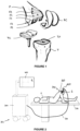
- FIG. 2 shows an overview of a surgical system according to the invention.
- a patient P is lying on an operating table 500, e.g. in view of total knee arthroplasty (TKA).
- TKA total knee arthroplasty
- an end effector such as a saw 2, which is intended to cut the tibial and femoral bones along at least one target plane - preferably, a plurality of target planes - is used by a user such as a surgeon.
- the end effector is held by the robotic device 100 and is constrained in each target plane by an actuation unit 4 (not shown in FIG. 2 , but better seen in subsequent drawings).
- the robotic device 100 is connected to a control unit 300 that controls the actuation unit.
- Said control unit typically comprises power supply, AC/DC converters, motion controllers to power the motors of the actuation unit, fuses, real-time control system interface circuits.
- the system also comprises a tracking unit 200, such that the relative pose of the device and the anatomical structure to be cut is tracked in real time and is shared between a real time control unit and a planning system.
- At least one coordinate system is attached to the anatomical structure while at least one coordinate system is attached to the end effector and to the robotic device.
- the tracking unit measures the relative motions between both coordinate systems in real time.
- Real time means high frequencies greater than twenty Hertz, preferably in the range of one hundred to five hundred Hertz, with low latency, ideally less than five milliseconds.
- the data obtained by the tracking unit are transferred to the control unit 300 via any suitable connection, with wires 301 or wireless, with low latency.
- the real-time control unit is able to carry out the proposed real-time control algorithms at a reasonably high frequency with low additional latency.
- the real-time control unit computes in real time the position of the end effector with respect to a target plane depending on said measured pose.
- connection is represented by a wire 301 but it may instead be wireless if the robotic device is battery-powered.
- the control unit and tracking unit may be arranged in a cart 302 that can be moved in the operating room. They can be also mounted on separate carts, articulated holding arms, lighting systems, or the tracking unit can be also mounted directly on the anatomical structure or on some parts attached to the robotic device.
- the end effector can rigidly support an electromagnetic emitter while electromagnetic sensors can be attached to the anatomical structure.
- the system may also comprise a visual user interface 400 that is intended to display feedback information to a user and enable system configuration by the user.
- the feedback information may comprise:
- Said user interface 400 may advantageously comprise a screen, which may be located on a cart in the operating room, e.g. on the same cart 302 as the control unit and tracking unit, or on a separate cart, or attached to the walls or the celling of the operating room.
- the user interface may comprise an indicator that is arranged on the robotic device itself to provide information to the user.
- Said indicator can be made of LEDs arranged to indicate arrows, numbers or letters, or a miniature display.
- a surgical system wherein the control unit, tracking unit and/or user interface are embedded in the robotic device itself would still be within the scope of the invention, provided that the embedded units are powered by a sufficiently powerful power supply or battery and that their size and weight do not hinder the manipulation of the robotic device by the user.
- the embedded units are powered by a sufficiently powerful power supply or battery and that their size and weight do not hinder the manipulation of the robotic device by the user.
- micro cameras can be attached to the base of the actuation unit and markers can be attached to the anatomical structure and to the end effector.
- the end effector is a surgical saw attached to the actuation unit using a planar mechanism.
- the saw 2 comprises a casing 23 and a saw blade 22 that oscillates in a determined plane (called "cutting plane") relative to the casing 23 (see in particular FIGS. 6-9 ).
- the saw blade can be operated to cut the anatomical structure according to a target plane without requiring any cutting block, provided that the actuation unit 4 constrains the saw in the target plane in real time.
- the cutting plane is parallel to the longitudinal axis of the casing and the saw blade oscillates on both sides of this axis; such a saw is known in the medical field as a "sagittal saw".
- the casing is usually positioned relative to the planar mechanism so that the cutting plane is parallel to the plane of the planar mechanism.
- the saw blade moves back and forth along the longitudinal axis of the casing; such a saw is known in the medical field as a « reciprocating saw Surrey
- the casing is usually positioned relative to the planar mechanism so that the cutting plane is orthogonal to the plane of the planar mechanism.
- the end effector is a burr 2'.
- the burr tip can be spherical or cylindrical.
- a cylindrical shape burr tip with a three mm diameter constrained by the planar mechanism to remain in a plane parallel to the cylinder axis will be rigid enough to make large cuts and small enough to perform fast cutting.
- the end effector is a laser with a system to control the depth of penetration of the laser to avoid damaging soft tissues behind the bone.
- the end effector can be a high-pressure water jet or any other device that creates cuts in an anatomical structure.
- the end effector can be a scalpel or any electrically activated device such as a lancet or an ultrasonic cutter.
- the end effector is usually a saw, without any intended limitation of the invention.
- the actuation unit comprises at least three motorized degrees of freedom. Possibly, if there is redundancy, the actuation unit may comprise more than six motorized degrees of freedom.
- the actuation unit may have a serial architecture, a parallel architecture or a mixed serial and parallel architecture.
- the actuation unit 4 has a serial architecture made of a plurality of mobile segments, comprising from three to six motorized degrees of freedom, at least two of which being rotational degrees of freedom orthogonal to each other.
- the term "axis" designates the geometric rotation or translation axis corresponding to said degree of freedom.
- the axes and segments are numbered with increasing numbers starting from the base (i.e. the part of the robotic device that remains stationary while the robotic device works) and towards the terminal part that is connected to the end effector; this type of numbering is conventional for serial robotic architectures.
- the actuation unit has three motorized rotational degrees of freedom for adjusting the position and orientation of the cutting plane relative to each target plane.
- the actuation unit has two motorized rotational degrees of freedom and one or two motorized translational degrees of freedom.
- the actuation unit presents a parallel architecture comprising a base and a platform selectively orientable relative to the base.
- the platform is linked to the base by a plurality of links each providing a degree of freedom in rotation, and if appropriate, also in translation.
- Various embodiments of parallel architecture exist, such as hexapods, Hayward wrists, Agrawal wrists, Gosselin's agile eyes, Tesar wrists, Cheng wrists, etc.
- the components of the actuation unit may be integrated in an optimal way such that the robotic device remains as compact and light as possible while remaining strong enough to be able to hold the planar articulation and the end effector, as well as resisting to some normal pressure applied by the user when he/she manipulates the end effector. This may be especially the case if the actuation unit has at most five motorized degrees of freedom.
- the architecture of the actuation unit may enable additional movements - which can be motorized or not - within the cutting plane. However, it is not excluded to obtain such a compacity with an architecture having six degrees of freedom or more.
- the robotic device may not be as compact as in the embodiments described above, and the robotic device can thus rather be assimilated as a large surgical robot.
- the robot 1000 comprises an arm 1001 having a serial architecture comprising six motorized degrees of freedom, a planar mechanism 24 connecting the last segment of the arm to an end effector 2.
- the robot is used with a tracking unit configured to determine in real time the pose of the cutting plane with respect to the coordinate system of the anatomical structure of the patient.
- the tracking unit comprises at least one tracker (not shown) configured to be attached to the anatomical structure, a tracker 202 attached to a segment of the arm of the robot and a tracker 203 attached to the end effector 2.
- planar mechanism since the planar mechanism is very close to the surgical field, it has to remain compact and thus prone to bending under efforts exerted by the surgeon when cutting. Even if the large surgical robot is accurate, it cannot itself compensate for such bending of the planar mechanism. However, using a tracker on the end effector and implementing the above-mentioned compensation method allows overcoming this problem.
- a compact actuation unit presents a lower inertia - especially according to the first axis - and thus a greater responsiveness required in particular to compensate for bone motion in real time.
- the robotic device may be held by a holding arm, especially if the robotic device is compact and lightweight, whatever the number of its degrees of freedom.
- the holding arm does not require any invasive action onto the patient while fully supporting the weight of the robotic device.
- Such a holding arm supports the actuation unit and is suited to be connected to a mechanical support such as an operating table, a leg holder or mounted on a mobile cart which wheels can be blocked.
- a leg holder is an adjustable mechanism configured to maintain the leg in a given flexed position when the patient lies on the operating table.
- the holding arm is made of several articulated segments using ball-and-socket joints, rotational and/or translational joints.
- the holding arm is lockable, either manually by a knob (mechanical locking system) or actively by a dedicated actuator of a locking system.
- the locking system may be an electrical system, a piezoelectric system, a hydraulic system, a pneumatic system or a combination of such systems (e.g. a hydraulic cylinder driven by an electric motor).
- company SMITH & NEPHEW sells a passive holding arm, actively lockable, named SPIDER TM .
- the actuator can be a button, a foot switch, a remote button, etc. To manipulate the robotic device, the user has to maintain the actuator activated until the desired pose of the robotic device has been achieved.
- the holding arm supports the weight of the robotic device and maintains it in a rough positioning relative to the anatomical structure to be treated. It limits the movements of the user when operating the device - and, in advantageous embodiments, also damps movements of the user and/or the patient, vibrations of the end effector and reaction forces caused by movements of the actuation unit.
- the holding arm is passive.
- the holding arm may be braked progressively depending on the distance between the robotic device and a target position of the robotic device relative to a tracker fixed to the patient.
- the braking force may be inversely proportional to the distance of the robotic device to its target position.
- one or several concentric volumes e.g. cubes or spheres
- the braking force may adjust depending on the presence of the robotic device in one of said volumes.
- feedback information may be provided in the form of a light or acoustic signal.
- a variable flash frequency and/or intensity of a light signal may indicate the distance between the robotic device and its target position.
- a variable frequency, repeat speed and/or amplitude of an acoustic signal may indicate such a distance.
- the braking is not full, so that the user is always able to manipulate the robotic device until its final desired position.
- the holding arm is then locked upon an action from the user (e.g. by operating the actuator, e.g. releasing or pushing a button). If the user wants to move the robotic device again, he/she has to operate the actuator again, which frees the holding arm - possibly with a braking force as described above. If a new target position of the robotic device is defined, new braking volumes are defined, and the braking is adjusted based on said new volumes.
- the holding arm is equipped with weights to counterbalance the weight of the control unit, as it is commonly used for carrying and placing microscopes in the surgical field for example.
- the holding arm has a vertical translation with a spring mechanism to compensate for the weight of the global system, then it has a serial architecture with a large planar structure made of three parallel and vertical axes. Each axis is equipped with a locking system.
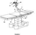
- FIG. 4 illustrates an embodiment of the holding arm 5, which is fixed to a rail 501 of the operating table 500 by a clamp 502.
- the holding arm is formed of the following kinematic links, in a sequence starting from the clamp: a pivot link 51 and a ball joint 52.
- the central module 53 is provided with an actuator 54 that allows unlocking the holding arm when pushed.
- an actuator could be arranged on a higher part of the holding arm so as to manipulate the arm and the robotic device easily in case the user wants to change the position of the robotic device relative to the anatomical structure.
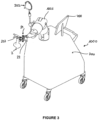
- FIG. 5 illustrates another embodiment of the holding arm 5, which is fixed to a rail of the operating table 500 by a clamp 501.
- the holding arm is formed of six pivot links 51.
- the holding arm may be locked by an actuator (not shown).
- connection between the holding arm and the actuation unit is as close as possible to the first segment of the actuation unit or to the center of gravity of the robotic device in order to minimize any lever-arm effect.
- the part of the actuation unit that is attached to the holding arm is called the base of the robotic device.
- the first segment of the actuation unit may be fixed relative to the holding arm.
- the second segment of the actuation unit is necessarily mobile relative to the first segment.
- This architecture is advantageous in that it minimizes the weight of the moving components of the actuation unit.
- the robotic device may be more responsive, which is favorable to real time control of the cutting plane.
- the first segment of the actuation unit may be mobile relative to the holding arm.
- the first and second segments are preferably embedded in a single housing.
- the base of the actuation unit may be fixed relative to the holding arm.
- the actuation unit 4 is controlled by the control unit 300.
- the control unit may be integrated in the robotic device, or remote from the robotic device.
- the end effector is coupled to the actuation unit by a planar mechanism designated under reference 24 throughout the set of drawings, the planar mechanism being configured to constrain the movement of the end effector within the cutting plane.
- the end effector can be decoupled from the planar mechanism.
- the attachment means for the end effector provides reproducible fixation.
- planar mechanism can be made of only one rotation axis and then one translation axis that carries the end effector along its longitudinal direction. Otherwise, the planar mechanism can be made of two or more rotation axes. Alternatively, the planar mechanism can be made of two orthogonal translation axes and then a rotational axis. According to another embodiment, the planar mechanism can be a slider in the form of an arch, including a rotation axis, and then a translation axis that carries the end effector.
- FIGS. 6-9 illustrate various non-limitative embodiments of the planar mechanism.
- the actuation unit is represented with a serial architecture and the end effector is represented as a saw, the invention could be implemented with any other type of actuation unit or end effector.
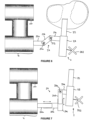
- the arrows indicate the degrees of freedom of the planar mechanism in each embodiment.
- FIG. 6 illustrates a planar mechanism 24 comprising three linear segments 24a, 24b, 24c articulated about two rotation axes 25a, 25b that are orthogonal to the segments.
- the first segment 24a is rigidly coupled to the actuation unit and the third segment is rigidly coupled to the end effector.
- FIG. 7 illustrates a planar mechanism 24 comprising five linear segments 24a-24e.
- the first and second segments 24a, 24b are in sliding engagement relative to each other, as well as the third and fourth segments 24c, 24d.
- the second and third segments 24b, 24c are rigidly coupled to each other and may form a single piece.
- the fourth and fifth segments 24d, 24e are articulated about a rotation axis 25a that is orthogonal to the segments.
- the first segment 24a is rigidly coupled to the actuation unit and the fifth segment 24e is rigidly coupled to the end effector.
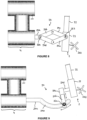
- FIG. 8 illustrates a planar mechanism 24 comprising five linear segments 24a-24e.
- the first segment 24a is rigidly coupled to the actuation unit 4.
- Two pairs of segments (respectively 24b-24c and 24d-24e) are connected to form a parallelogram.
- the segments 24b, 24d are articulated on the first segment 24a by a rotation axis 24a that is orthogonal to the segments.
- the segments 24c, 24e are coupled to the end effector by a rotation axis 25b.
- the segments of each pair 24b-24c and 24d-24e are articulated about a respective axis that is orthogonal to said segments.
- FIG. 9 illustrates a planar mechanism 24 comprising a first segment 24a including a curved slot 240, a second linear segment 24b coupled to the first segment 24a via an axis 25a orthogonal to said segments.
- the axis 25a is able to slide within the curved slot 240, and the second segment 24b is rotatable relative to the axis 25a.
- a third linear segment 24c is in sliding engagement with the second segment, and rigidly connected to a fourth linear segment 24d that carries the end effector.
- the third and fourth linear segments 24c, 24b may form a single piece.
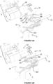
- FIGS. 10A and 10B illustrate an embodiment of the robotic device, wherein the planar mechanism is of the type illustrated in FIG. 6 .
- the articulation axes 25a, 25b have a circular shape, which does not restrict the range of rotation of each linear segment relative to another one. This may result in some unsuitable configurations of the planar mechanism that may limit or even hinder some movements of the end effector 2 (see FIG. 10A ), and/or that may cause the end effector 2 to collide with the actuation unit 4 (see FIG. 10B ).
- FIGS. 11A and 11B illustrate an alternative embodiment of the robotic device comprising stops arranged on at least one axis 25a of the planar mechanism 24 to limit the angle of rotation of the segments relative to each other.
- Said stops may consist in bulges 250a, 250b extending radially on the circumference of the articulations axes. Said bulges are located in a selected position so as to interfere with a complementary part 26 when an extreme position has been reached, thereby preventing any further rotation of the linear segment.
- the stop 250a that is arranged on the first axis 25a on the side of the actuation unit prevents the second axis 25b from being moved towards the top of the figure.
- FIG. 11A illustrates an alternative embodiment of the robotic device comprising stops arranged on at least one axis 25a of the planar mechanism 24 to limit the angle of rotation of the segments relative to each other.
- Said stops may consist in bulges 250a, 250b extending radially on the circumference of the articulations axes
- the other stop 250b that is arranged on the first axis 25a prevents the end effector 2 from being brought in contact with the actuation unit 4.
- the stop 250b also allows the user to find more easily the locking position of the end effector, that will be described with reference to FIGS. 12A-12B and 13A-13B .
- the planar mechanism is passive, meaning that the mechanism is not motorized and can be freely manipulated by the user.
- One advantage of such a passive mechanism is to preserve all the perceptions of the user when the saw is manipulated in the bone. Thanks to the planar mechanism, the user remains free to move the cutting tool within the target plane, thereby enjoying his/her usual feeling when accomplishing the surgical gesture. This also provides for a greater safety of use of the robotic device, since the user's intervention is always required to perform the cut. For example, surgeons are used to freely manipulate a saw in a cutting block and to detect when the saw blade has reached the back of the bone by sensing changes in the bone resistance, and this perception is fully preserved with a passive planar mechanism that has very low friction at its joints. In this respect, the planar mechanism is advantageously provided with bearings that provide such a low friction for the various degrees of freedom.
- the planar mechanism may advantageously be made of lightweight and compact components so as to limit its bulkiness and thus to allow placing the end effector in any desired pose relative to the patient.
- the invention provides for a control unit that is configured to implement a control loop that allows compensating for any offset between the real pose of the end effector and its theoretical one (i.e. the pose assuming that the planar mechanism is perfectly stiff and always maintaining the end effector within the intended plane).
- the control loop uses a continuous tracking of the end effector.
- planar mechanism may comprise a locking system for locking each of its degrees of freedom once a desired configuration has been achieved.
- the robotic device may advantageously comprise a locking system for locking the end effector in a fixed position relative to the actuation unit when the robotic device has to move to a new position.
- Various locking systems may be used (mechanical, magnetic, etc.).
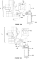
- FIGS. 12A and 12B illustrate an embodiment of a mechanical locking system, respectively in unlocked and locked (rest) position.
- the terminal part 40 of the actuation unit 4 is rigidly attached to a curved support 41 into which the planar mechanism 24 is arranged.
- the end effector 2 is intended to face a part 410 of the curved support 41 in its rest position.
- Said part 410 of the curved support 41 comprises an opening 411 for receiving a locking member 231 protruding from an intermediate part 230 attached to the end effector 2, and a latch (not shown) for maintaining the locking member 231 fixed to the curved support 41 once it has been inserted into the opening 411.
- the curved support 41 also comprises a button 412 coupled to the latch to release the locking member 231 when said button 412 is pressed by a user.
- FIGS. 13A and 13B illustrate an embodiment of a magnetic locking system, respectively in unlocked and locked (rest) position.
- the terminal part 40 of the actuation 4 unit is rigidly attached to a curved support 41 into which the planar mechanism 24 is arranged.
- the end effector 2 is intended to face a part 410 of the curved support 41 in its rest position.
- Said part 410 of the curved support comprises a magnet 413 configured to retain a corresponding magnetic element 232 on the end effector (or on a part 230 attached to the end effector).
- the magnetic force is selected to be high enough to strongly maintain the end effector onto the support, while allowing a user to release the end effector in a smooth way.
- the invention could be implemented with any other configuration of such a locking system.
- the magnet may be replaced by an electromagnet.
- One advantage of the above-described locking system of the planar mechanism or of the end effector is that the end effector is maintained fixed relative to the terminal component of the actuation unit when the robotic device is being moved, which avoids any undesired movement of the end effector during this movement, which could cause the end effector to hit the patient, the user or an element of the operating room.
- the actuation unit and end effector form a compact assembly, which is easier to move to a new desired position.
- the locking unit may be provided with detectors allowing detecting whether the end effector is locked into the rest position or not.
- the control unit may be configured to allow movement of the actuation unit only if such a locking into the rest position is detected.
- control unit may allow movement of the actuation unit only if the tracking data show that the end effector is distant enough from the patient so as to avoid hitting him/her during said movement.
- the actuation unit and planar mechanism sterile components, to be sterilized before each intervention.
- the actuation unit with its cables and equipped with the planar mechanism are covered by a single-use sterile drape. Additional components of the system can be also protected under the sterile drape. This has the advantage of facilitating and reducing cost of manufacturing and design, but also of being used easily for multiple consecutive surgeries without requiring re-sterilization of the device.
- the end effector itself is sterile, like any conventional surgical tool. Typically, it is sterilized before each intervention using autoclave. Different types of mechanical adaptors between the sterile drape and the end effector can be provided.
- Such adaptor does not require a very precise reproducible fixation if the saw contains a tracking element (described in more detail below), which increases the accuracy of the global system.
- the sterile drape covers the planar mechanism to facilitate the design and manufacturing of the device. For example, this design allows the use of ball-bearings mechanisms that would be difficult to autoclave.
- the user plans the intervention on the planning system, based on pre-operative and/or intra-operative medical images and data.
- This planning step allows determining each target plane suited to perform the cut of the anatomical structure. It is specific to each application.
- planning the implantation of a prosthesis on a knee usually results in the definition of five target planes on the femur and one on the tibia. It is also possible to define more than five cutting planes for fixing a prosthesis to a bone in order to optimize the shape of the prosthesis based on individual anatomy for example.
- the planning system may form part of the surgical system according to the invention; otherwise, the planning system may be provided separately and connected to the control unit.
- the user may either use preoperative data/images together with intra-operative registration methods, or use directly intraoperative data/images.
- the result of the planning consists of at least one target plane, the pose of each plane being determined in the coordinate system of the anatomical structure to be cut.
- the pose of each target plane is then transferred to the control unit.
- the control unit initializes its sub-systems and the device is ready to use.
- the articulated holding arm (if any) is moved by a user so as to bring the actuation unit in a rough suitable position relative to the anatomical structure, and is then locked. Then, the end effector is attached to the planar mechanism.
- the tracking unit continuously feeds back tracking information to the control unit for recalculation and visualization purposes.
- the system also comprises a tracking unit 200 configured to determine in real time the pose of the end effector with respect to the anatomical structure to be cut.
- the tracking unit may typically comprise a tracking system, which is known per se.
- Tracking systems commonly used in computer-assisted surgery use a variety of different technologies (passive optical, active optical, electromagnetic, inertia with gyroscopic measurements, ultrasonic, etc.) that can be used individually or in combination.
- the tracking system is based on passive optical technology.
- the tracking unit comprises at least one tracker that may be attached to any component of the actuation unit, e.g. to one of the mobile segments.
- each component of the actuation unit is known in real time thanks to encoders or sensors of the motors, and a calibrated model of the robot that includes all axes and distances of the robot segments.
- a calibrated model of the robot that includes all axes and distances of the robot segments.
- it is possible to calculate the relative positions of all segments so if one measurement is known in a coordinate system attached to the robot basis using an external tracker, then any segment position is also known in the same coordinate system.
- a tracker is attached to the base of the actuation unit and a second tracker is attached to the anatomical structure, then the pose of any component of the actuation unit is known in the coordinate system attached to the tracker of the anatomical structure.
- At least one tracker is rigidly attached to the patient's anatomical structure to be cut so as to allow localizing the cutting plane relative to the coordinate system of this anatomical structure to be cut.
- Micro or macro motions of the robotic device with respect to the anatomical structure to be cut are compensated within a tolerance range and a given time frame that defines the precision of the device.
- the compensation procedure cannot rely solely on the geometrical model of the robotic device, which is never perfect due to mechanical backlashes and irregularities, as well as structural deformations that are changing depending on the relative positions of the end effector and the various parts of the robotic device.
- planar mechanism itself may slightly bend, especially if it is made of a lightweight and compact structure. As a result, its components do not have the same position and orientation. Indeed, a variable shift on the position and orientation of the planar mechanism is observed, and the compensation of the end effector position is never perfect, preventing the robotic device from converging to the target plane. In such case, either the robotic device oscillates, or it converges to a position which is shifted from the target plane.
- an additional tracker is rigidly attached to the end effector. This additional tracker allows determining reliably the position and orientation of the end effector in the coordinate system of the robotic device, taking into account any mechanical backlash that may exist between the actuation unit and the end effector.
- Said end of the planar mechanism may comprise an interface capable of receiving any type of end effector as mentioned above (sagittal saw, reciprocal saw, burr%) but also other surgical tools such as a drill guide to be used to drill the pegs for implanting the prosthesis, and/or a cutting guide, etc.
- the drill guide can have a toothed end intended to grip into the surface of the anatomical structure where a hole has to be drilled.
- a handle is provided at the opposite end of the drill guide to facilitate its manipulation by the surgeon.
- the drill may carry a tracker, instead of having the tracker carried by the end of the planar mechanism.
- the position of each segment of the planar mechanism can be determined, which provides redundant information on the position of the end effector.
- the compensation of relative motion between the robotic device and the anatomical structure using the additional tracker rigidly attached to the end effector or to the end of the planar mechanism may be implemented as follows, with reference to the control loop shown in FIG. 14 .
- the additional tracker allows relying on the actual position of the end effector or of the end of the planar mechanism instead of the theoretical position of the planar mechanism.
- the association of the tracker attached to the end effector and the tracker attached to the actuation unit enables dynamic estimation of the alignment error between the two. This alignment error is then used to correct the position and orientation of the planar mechanism to the target plane.
- FIG. 14 is a flowchart describing the control loop allowing the compensation.
- step S'1 new poses of the robotic device, the end effector and the anatomical structure are determined using localization information provided by the trackers.
- step S'2 a deviation d between the plane of the end effector (cutting plane) and the target plane is computed.
- step S'1 If the deviation d is less than a threshold thr, the end effector can be operated and a new pose of the robotic device and anatomical structure is determined (step S'1).
- step S'3 the plane of the end effector (cutting plane) and the target plane are projected in the coordinate system of the robotic device.
- step S'4 a correction matrix T err corresponding to a rigid transformation between the plane of the planar mechanism and the plane of the end effector is computed.
- step S'5 the target plane is updated with T err .
- step S'6 a new attitude of the robotic device is computed to reach the target plane. This computation determines the movements to be applied by the motors of the actuation unit.
- step S'7 the motors of the actuation unit are activated in accordance with step S'6.
- step S'1 the new position of the robotic device and anatomical structure is determined.
- the correction matrix T err may vary depending on the current extension of the planar mechanism and therefore it is not constant. It also depends on the mechanical backlash and flexion of the planar mechanism, the position of the robot, and other factors.
- the correction matrix is calculated in real time, such that the deviation of T err between two calculations is not significant, considering reasonable motions of the saw by the user. This method of correction is extremely precise and efficient for compensating any mechanical defects, backlash and errors in the model.
- this compensation loop also allows at least partially compensating for backlash and flexion of the actuation unit.
- the attachment of the trackers to the end effector and/or actuation unit is reversible and reproducible.
- a tracker attached to the anatomical structure is designated by reference 201
- a tracker attached to the actuation unit or to the holding arm is designated by reference 202
- a tracker attached to the end effector is designated by reference 203.
- a user interface is defined so as to indicate the user at least one potential position and orientation of the actuation unit suitable for aligning the cutting plane with a target plane.
- the user interface may provide information to the user to guide him or her to reposition the actuation unit in an optimal pose to enable alignment of the cutting plane with a target plane.
- the user interface may also indicate to the user if all targeted cutting planes can be reached from the current position of the actuation unit, and if not, in which direction to move to reach an optimal position.
- Said user interface may be visual and/or acoustic.
- the user interface may comprise a screen connected to the control unit, e.g. the screen 400 shown on FIG. 2 .
- a realistic 3D model of the anatomical structure may be displayed on the screen, along with a real-time representation of the end effector (e.g. envelope of the oscillating blade).
- a visualization is made possible by obtaining tracking data from the tracker attached to the end effector or, if any, by obtaining position information from the encoders of the planar mechanism. For instance, if the end effector is a saw, the user can visualize the position of the tip of the saw blade relative to the bone, to ensure that the tip of the saw blade does not exit from the bone.
- the control system checks in real time if the saw can be aligned with a target plane. If the robotic device is moved such that the saw cannot be aligned with said target plane - e.g. in case of vibrations, and/or an involuntary movement of the patient -, then the information provided to the user may change, e.g. the color of the arrow is changed or an acoustical feedback is produced.
- the user interface comprises visual indicators such as LEDs. These LEDs may be arranged on a supporting surface that is fixed to the robotic device. Alternatively, the LEDs may be arranged on a support separate from the robotic device and connected to it by a wire. Alternatively, the LEDs may be arranged on a support separate from the robotic device and wirelessly linked to the robotic device. Such a separate support can be placed in the vicinity of the robotic device / end effector, in the user's field of view.
- Said indicators are intended to instruct the user not to activate the end effector, in case the robotic device is not able to compensate for a misalignment between the cutting plane and the target plane. For example, a red and blinking light is turned on as soon as the trackers mounted on the anatomical structure and/or the end effector are not visible. It is turned off or changed to a green light as soon as the visibility of trackers is restored.
- Another way of providing information to the user is to use numerical displays (e.g. provided by LCD screens) that represent virtual spirit levels.
- the general orientation of the robotic device can be adjusted by the user based on one virtual spirit level on top of the robotic device and another one on a side (opposite to the patient's leg) of the robotic device.
- the distance of the robotic device can be adjusted using a support unit, and/or using indicators such as LEDs representing an arrow pointing the desired direction, and/or via the screen of the user interface.
- the system further comprises a control unit which is intended to control the pose of the saw in an optimal way in order to align it with a target plane.
- control unit may be coupled to the end effector used to perform the cut and configured to allow the actuation of the end effector only when the cutting plane is aligned with the target plane. This increases the safety of the system.
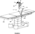
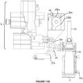
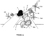
- FIG. 15 illustrates a setup of the robotic device, with a burr 2' as the end effector.
- the trackers illustrated in the figures are optical trackers, it should be noted that any other tracking technology (e.g. electromagnetic) may be used.
- the terminal part of the actuation unit could be provided with an electromagnetic emitter and the end effector with an electromagnetic receiver.
Landscapes
- Health & Medical Sciences (AREA)
- Surgery (AREA)
- Life Sciences & Earth Sciences (AREA)
- Engineering & Computer Science (AREA)
- Public Health (AREA)
- Biomedical Technology (AREA)
- Heart & Thoracic Surgery (AREA)
- Medical Informatics (AREA)
- Molecular Biology (AREA)
- Animal Behavior & Ethology (AREA)
- General Health & Medical Sciences (AREA)
- Nuclear Medicine, Radiotherapy & Molecular Imaging (AREA)
- Veterinary Medicine (AREA)
- Oral & Maxillofacial Surgery (AREA)
- Robotics (AREA)
- Dentistry (AREA)
- Orthopedic Medicine & Surgery (AREA)
- Transplantation (AREA)
- Physical Education & Sports Medicine (AREA)
- Physics & Mathematics (AREA)
- Pathology (AREA)
- Otolaryngology (AREA)
- Electromagnetism (AREA)
- Optics & Photonics (AREA)
- Mechanical Engineering (AREA)
- Human Computer Interaction (AREA)
- Manipulator (AREA)
Description
- The invention relates to a robotic system for cutting an anatomical structure of a patient.
- Total knee arthroplasty typically requires cutting both the femoral epiphysis and tibial epiphysis in order to remove the damaged bone and cartilage and install a knee prosthesis.
- To that end, a surgeon has to carry out five or more cuts on the femur and one or more cuts on the tibia by using an oscillating saw through cutting blocks.
-
FIG. 1 is a schematic perspective view of a knee intended to receive a knee prosthesis including a femoral component FC and a tibial component TC. Generally, the cuts to be made on the femur F are: a distal cut along plane F1, an anterior cut along plane F2, a posterior cut along plane F3, and anterior and posterior chamfers F4, F5 connecting the distal plane and the anterior, respectively posterior, plane. A cut has to be made on the tibia T along plane T1. - In order for the surgeon to carry out cutting along all these planes accurately and in a reduced time, robotic systems have been developed that carry and position the cutting block in accordance with a target plane.
- The cutting block generates a certain inaccuracy since the orientation of the saw blade may slightly vary when inserted into a slot of the cutting block, which may change the orientation of the cutting plane relative to the target plane.
- In order to improve accuracy of the cutting procedure, it may be desirable to have the saw itself guided by the robotic system.
- Two types of robotic systems exist.
- On the one hand, large surgical robots with six or more degrees of freedom are very stiff but they are also very cumbersome and expensive. Besides, they have a considerable inertia (especially on the first mobile segment), which is not compatible with real time control of the cutting plane. In addition, these robots are either active or reactive, thus depriving at least partially the user (usually the surgeon) from his/her usual feeling and freedom when accomplishing the surgical gesture.
- On the other hand, existing small, lightweight robots that allow the user to freely manipulate the saw cannot be used if they are not rigidly attached to the anatomical structure to be cut.
- Roth et al. describe attaching a handheld saw to an end of a robot by means of a planar mechanism. The planar mechanism constrains the saw in a given plane, which is adjusted relative to the patient by the robot based on a preoperative planning and on tracking data of the bone to be cut. However, in this system, only the pose of the connection between the planar mechanism and the last segment of the robot can be accurately determined in the best case. In other words, the pose of the saw relative to the robot cannot be precisely known. Thus, unless the planar mechanism is perfectly stiff, there may be a difference between the real pose of the saw and the expected one, which results in a misalignment of the cutting plane and the target plane. Making the planar mechanism perfectly stiff would be difficult to achieve and would also drastically increase its weight and bulkiness. Prior art is disclosed in
US 8 010 180 ,WO 2012/131660 ,US 2009/228145 ,WO 2012/131658 ,WO 2007/045810 . - A goal of the invention is to provide a surgical system intended to guide an end effector to cut an anatomical bony structure of a patient according to at least one target plane, which does not require any invasive attachment to the patient's bone while controlling precisely the position and orientation of the end effector to reach the target plane.
- Accordingly, the invention provides a surgical system for cutting an anatomical structure of a patient according to at least one target plane defined in a coordinate system of the anatomical structure, comprising:
- (i) a robotic device comprising:
- an end effector,
- an actuation unit having at least three motorized degrees of freedom, configured for adjusting a position and orientation of the end effector (2) relative to each target plane,
- a passive planar mechanism connecting the terminal part of the actuation unit to the end effector, the passive planar mechanism being configured to constrain movement of the end effector only inside a plane, the passive planar mechanism allowing a user to freely move the end effector inside said plane according to two degrees of freedom ;
- (ii) a tracker rigidly attached to the end effector,
- (iii) a tracking unit configured to determine in real time the pose of the end effector with respect to the coordinate system of the anatomical structure,
- (iv) a control unit configured to determine the pose of the end effector with respect to the target plane and to control the actuation unit so as to bring the cutting plane into alignment with the target plane.
- Advantageously, the control unit is further configured to implement a control loop comprising the following steps:
- (S'1) determining poses of the actuation unit, the end effector and the anatomical structure using localization information provided by the tracking unit;
- (S'2) computing a deviation between the cutting plane and the target plane;
- if the deviation is less than a threshold, allowing operation of the end effector and returning to step (S'1) to determine a new pose of the actuation unit, end effector and anatomical structure;
- if the deviation is greater than or equal to the threshold, projecting (S'3) the cutting plane and the target plane in the coordinate system of the actuation unit,
- (S'4) computing a transformation between the plane of the planar mechanism and the cutting plane;
- (S'5) updating the target plane with the transformation computed in step (S'4);
- (S'6) computing a new attitude of the actuation unit to align the cutting plane with the updated target plane, and determining the movements to be applied by the motors of the actuation unit;
- activating the actuation unit (4) to apply said movements.
- According to an embodiment, the end effector is a surgical saw comprising a saw blade configured to oscillate within a determined cutting plane. The cutting plane may be parallel to the plane of the planar mechanism. Alternatively, the cutting plane may be orthogonal to the plane of the planar mechanism.
- According to an embodiment, the end effector is a burr.
- According to an embodiment, the end effector is a laser.
- According to an embodiment, the end effector is a high-pressure water jet.
- According to an embodiment, the end effector is a scalpel or a lancet adapted for cutting soft tissues.
- Advantageously, each degree of freedom of the planar mechanism may be provided with at least one encoder.
- According to an embodiment, the planar mechanism comprises a locking system configured to lock each of its degrees of freedom.
- According to an embodiment, the planar mechanism comprises at least two linear segments coupled by an articulation axis and said articulation axis is provided with stops configured to limit the range of rotation of the linear segments relative to each other. Said stops may be bulges extending radially outwardly from the articulation axis.
- Advantageously, the system may comprise a locking system for locking the end effector to the actuation unit in a rest position.
- The locking system preferably comprises a support rigidly coupled to the terminal part of the actuation unit and an intermediate part rigidly attached to the end effector.
- According to an embodiment, the end effector locking system is a mechanical locking system. The support may comprise an opening provided with a latch and the intermediate part may comprise a protruding locking member configured to be inserted into the opening and retained by the latch, the support further comprising a button coupled to the latch and configured to release the locking member.
- According to another embodiment, the end effector locking system is a magnetic locking system. The support may comprise a magnet or an electromagnet and the intermediate part comprises a magnetic element.
- According to an embodiment, the tracking unit is an optical tracking unit. Alternatively, the tracking unit is an electromagnetic tracking unit.
- According to an embodiment, the system further comprises a passive lockable articulated arm holding the robotic device.
- Other features, embodiments and advantages of the invention will be apparent from the detailed description that follows, based on the appended drawings wherein:
-
FIG. 1 schematically illustrates the cuts to be made into a femur and a tibia in order to implant a knee prosthesis; -
FIG. 2 shows an overview of a surgical system according to the invention; -
FIG. 3 is a perspective view of a robotic device according to a first embodiment of the invention; -
FIG. 4 is a perspective view of a robotic device according to a second embodiment of the invention; -
FIG. 5 is a perspective view of a robotic device according to a third embodiment of the invention; -
FIGS. 6-9 show various embodiments of the planar mechanism connecting the end effector to the actuation unit; -
FIG. 10A and 10B illustrate an embodiment of the robotic device without limitation to the range of rotation of the segments of the planar mechanism; -
FIGS. 11A and11B illustrate an embodiment of the robotic device with stops configured to limit the range of rotation of the segments of the planar mechanism; -
FIGS. 12A and 12B illustrate an embodiment of a mechanical locking system for securing the end effector to the actuation unit, respectively in unlocked and locked configuration; -
FIGS. 13A and 13B illustrate an embodiment of a magnetic locking system for securing the end effector to the actuation unit, respectively in unlocked and locked configuration; -
FIG. 14 represents a compensation control loop implemented by the control unit. -
FIG. 15 illustrates an embodiment of the robotic device wherein the end effector is a burr. - The following description is focused on knee surgery, in particular total knee arthroplasty (TKA), in which case the anatomical structure to be cut is a joint formed of the femur and the tibia.
- However, the invention is not limited to this specific application, but can be applied to various applications where there is a need to perform cuts along at least one plane in a bony anatomy. In general, the invention can be used in any surgical intervention requiring at least one osteotomy step. In particular but not limited to, the invention could also be implemented in the following surgical applications: unicompartmental knee arthroplasty (UKA), tibial or femoral osteotomy, patella resurfacing, hallux valgus surgery, hip surgery for cutting the proximal femur, shoulder surgery for cutting the humeral head, spine surgery for correcting deformities and performing an osteotomy of the vertebral body, ankle surgery, maxillofacial surgery.
- As will be explained in further detail below, the device is used in a context in which at least one target plane along which the anatomical structure has to be cut is planned before performing the cut(s).
- Planning of at least one target plane is performed using patient's pre-operative images (e.g. CT, MRI, Ultrasound images, 2D or 3D X-rays in combination with statistical shape models, PET, etc.) or intra-operative 3D data (e.g. intra-operative CT or CBCT, intra-operative MRI, Ultrasound images, 2D or 3D intra-operative X-ray images, geometric data provided by localizing systems and providing 3D points, clouds of 3D points, surfaces reconstructed from clouds of 3D points, etc.), or both.
- Multiple computer-assisted surgery methods exist to register the target plane with a coordinate system attached to the anatomical structure to be cut, using images or geometric patient data collected during surgery.
- Typically, intra-operative images or data are used to register pre-operative images in a unique coordinate system attached to the anatomical structure, and usually represented by a tracker that can use any of computer assisted surgery technologies (optical tracker made of reflective markers, optical tracker made of active LEDs, electromagnetic trackers made of coils, combination of inertial sensors, ultrasonic sensors, RFID sensors, etc.).
- Using any of these conventional computer-assisted surgery methods results in that the target planes have a known geometric representation in a coordinate system attached to the anatomical structure to be cut, and whose movements are tracked in real-time by a tracking unit as it will be detailed below. Typically, the surgical planning step for total knee surgery results in five target planes defined in a coordinate system attached to a tracker fixed to the femur and one target plane defined in a coordinate system attached to a tracker fixed to the tibia.
-
FIG. 2 shows an overview of a surgical system according to the invention. - A patient P is lying on an operating table 500, e.g. in view of total knee arthroplasty (TKA).
- To that end, an end effector, such as a
saw 2, which is intended to cut the tibial and femoral bones along at least one target plane - preferably, a plurality of target planes - is used by a user such as a surgeon. - The end effector is held by the
robotic device 100 and is constrained in each target plane by an actuation unit 4 (not shown inFIG. 2 , but better seen in subsequent drawings). - The
robotic device 100 is connected to acontrol unit 300 that controls the actuation unit. - Said control unit typically comprises power supply, AC/DC converters, motion controllers to power the motors of the actuation unit, fuses, real-time control system interface circuits.
- The system also comprises a
tracking unit 200, such that the relative pose of the device and the anatomical structure to be cut is tracked in real time and is shared between a real time control unit and a planning system. - At least one coordinate system is attached to the anatomical structure while at least one coordinate system is attached to the end effector and to the robotic device.
- The tracking unit measures the relative motions between both coordinate systems in real time. Real time means high frequencies greater than twenty Hertz, preferably in the range of one hundred to five hundred Hertz, with low latency, ideally less than five milliseconds.
- The data obtained by the tracking unit are transferred to the
control unit 300 via any suitable connection, withwires 301 or wireless, with low latency. - The real-time control unit is able to carry out the proposed real-time control algorithms at a reasonably high frequency with low additional latency.
- The real-time control unit computes in real time the position of the end effector with respect to a target plane depending on said measured pose.
- In this figure, the connection is represented by a
wire 301 but it may instead be wireless if the robotic device is battery-powered. - The control unit and tracking unit may be arranged in a
cart 302 that can be moved in the operating room. They can be also mounted on separate carts, articulated holding arms, lighting systems, or the tracking unit can be also mounted directly on the anatomical structure or on some parts attached to the robotic device. For example, the end effector can rigidly support an electromagnetic emitter while electromagnetic sensors can be attached to the anatomical structure. - The system may also comprise a
visual user interface 400 that is intended to display feedback information to a user and enable system configuration by the user. The feedback information may comprise: - indication about a deviation (distance and/or angle) between the cutting plane and the target plane, before the anatomical structure is cut;
- indication about whether the target plane can be achieved with the current position of the robotic device;
- directions to reposition the actuation unit with respect to the anatomical structure to be cut in order to allow the actuation unit to align the cutting plane with the target plane;
- indication about a deviation (distance and/or angle) between the cutting plane and the target plane, while the anatomical structure is being cut;
- Said
user interface 400 may advantageously comprise a screen, which may be located on a cart in the operating room, e.g. on thesame cart 302 as the control unit and tracking unit, or on a separate cart, or attached to the walls or the celling of the operating room. - In addition to or instead of said screen, the user interface may comprise an indicator that is arranged on the robotic device itself to provide information to the user. Said indicator can be made of LEDs arranged to indicate arrows, numbers or letters, or a miniature display.
- A surgical system wherein the control unit, tracking unit and/or user interface are embedded in the robotic device itself would still be within the scope of the invention, provided that the embedded units are powered by a sufficiently powerful power supply or battery and that their size and weight do not hinder the manipulation of the robotic device by the user. For example, micro cameras can be attached to the base of the actuation unit and markers can be attached to the anatomical structure and to the end effector.
- According to an embodiment, the end effector is a surgical saw attached to the actuation unit using a planar mechanism. The
saw 2 comprises acasing 23 and asaw blade 22 that oscillates in a determined plane (called "cutting plane") relative to the casing 23 (see in particularFIGS. 6-9 ). Thus, the saw blade can be operated to cut the anatomical structure according to a target plane without requiring any cutting block, provided that theactuation unit 4 constrains the saw in the target plane in real time. Usually, the cutting plane is parallel to the longitudinal axis of the casing and the saw blade oscillates on both sides of this axis; such a saw is known in the medical field as a "sagittal saw". The casing is usually positioned relative to the planar mechanism so that the cutting plane is parallel to the plane of the planar mechanism. - According to an embodiment, the saw blade moves back and forth along the longitudinal axis of the casing; such a saw is known in the medical field as a « reciprocating saw ». The casing is usually positioned relative to the planar mechanism so that the cutting plane is orthogonal to the plane of the planar mechanism.
- According to an embodiment (see
FIG. 15 ), the end effector is a burr 2'. Indeed, especially if the burr tip is small (e.g. with a diameter of the order of three mm), the operation of the burr constrained in a cutting plane allows performing a planar cut. The burr tip can be spherical or cylindrical. Typically a cylindrical shape burr tip with a three mm diameter constrained by the planar mechanism to remain in a plane parallel to the cylinder axis will be rigid enough to make large cuts and small enough to perform fast cutting. - According to an embodiment (not illustrated), the end effector is a laser with a system to control the depth of penetration of the laser to avoid damaging soft tissues behind the bone.
- According to another embodiment (not illustrated), the end effector can be a high-pressure water jet or any other device that creates cuts in an anatomical structure.
- According to another embodiment, for cutting soft tissues, the end effector can be a scalpel or any electrically activated device such as a lancet or an ultrasonic cutter.
- In the drawings that are described below, the end effector is usually a saw, without any intended limitation of the invention.
- The actuation unit comprises at least three motorized degrees of freedom. Possibly, if there is redundancy, the actuation unit may comprise more than six motorized degrees of freedom.
- The actuation unit may have a serial architecture, a parallel architecture or a mixed serial and parallel architecture.
- According to an embodiment, the
actuation unit 4 has a serial architecture made of a plurality of mobile segments, comprising from three to six motorized degrees of freedom, at least two of which being rotational degrees of freedom orthogonal to each other. In the present text, the term "axis" designates the geometric rotation or translation axis corresponding to said degree of freedom. Besides, the axes and segments are numbered with increasing numbers starting from the base (i.e. the part of the robotic device that remains stationary while the robotic device works) and towards the terminal part that is connected to the end effector; this type of numbering is conventional for serial robotic architectures. - In some embodiments, the actuation unit has three motorized rotational degrees of freedom for adjusting the position and orientation of the cutting plane relative to each target plane.
- In other embodiments, the actuation unit has two motorized rotational degrees of freedom and one or two motorized translational degrees of freedom.
- According to another embodiment, the actuation unit presents a parallel architecture comprising a base and a platform selectively orientable relative to the base. To that end, the platform is linked to the base by a plurality of links each providing a degree of freedom in rotation, and if appropriate, also in translation. Various embodiments of parallel architecture exist, such as hexapods, Hayward wrists, Agrawal wrists, Gosselin's agile eyes, Tesar wrists, Cheng wrists, etc.
- Depending on the architecture of the actuation unit, the components of the actuation unit may be integrated in an optimal way such that the robotic device remains as compact and light as possible while remaining strong enough to be able to hold the planar articulation and the end effector, as well as resisting to some normal pressure applied by the user when he/she manipulates the end effector. This may be especially the case if the actuation unit has at most five motorized degrees of freedom. In some embodiments, the architecture of the actuation unit may enable additional movements - which can be motorized or not - within the cutting plane. However, it is not excluded to obtain such a compacity with an architecture having six degrees of freedom or more.
- In some embodiments the robotic device may not be as compact as in the embodiments described above, and the robotic device can thus rather be assimilated as a large surgical robot. As shown in
FIG. 3 , therobot 1000 comprises an arm 1001 having a serial architecture comprising six motorized degrees of freedom, aplanar mechanism 24 connecting the last segment of the arm to anend effector 2. The robot is used with a tracking unit configured to determine in real time the pose of the cutting plane with respect to the coordinate system of the anatomical structure of the patient. The tracking unit comprises at least one tracker (not shown) configured to be attached to the anatomical structure, atracker 202 attached to a segment of the arm of the robot and atracker 203 attached to theend effector 2. Indeed, since the planar mechanism is very close to the surgical field, it has to remain compact and thus prone to bending under efforts exerted by the surgeon when cutting. Even if the large surgical robot is accurate, it cannot itself compensate for such bending of the planar mechanism. However, using a tracker on the end effector and implementing the above-mentioned compensation method allows overcoming this problem. - As compared to such a large surgical robot, a compact actuation unit presents a lower inertia - especially according to the first axis - and thus a greater responsiveness required in particular to compensate for bone motion in real time.
- The robotic device may be held by a holding arm, especially if the robotic device is compact and lightweight, whatever the number of its degrees of freedom. The holding arm does not require any invasive action onto the patient while fully supporting the weight of the robotic device.
- Such a holding arm supports the actuation unit and is suited to be connected to a mechanical support such as an operating table, a leg holder or mounted on a mobile cart which wheels can be blocked. A leg holder is an adjustable mechanism configured to maintain the leg in a given flexed position when the patient lies on the operating table.
- The holding arm is made of several articulated segments using ball-and-socket joints, rotational and/or translational joints.
- The holding arm is lockable, either manually by a knob (mechanical locking system) or actively by a dedicated actuator of a locking system. The locking system may be an electrical system, a piezoelectric system, a hydraulic system, a pneumatic system or a combination of such systems (e.g. a hydraulic cylinder driven by an electric motor). For example, company SMITH & NEPHEW sells a passive holding arm, actively lockable, named SPIDER™. The actuator can be a button, a foot switch, a remote button, etc. To manipulate the robotic device, the user has to maintain the actuator activated until the desired pose of the robotic device has been achieved.
- The holding arm supports the weight of the robotic device and maintains it in a rough positioning relative to the anatomical structure to be treated. It limits the movements of the user when operating the device - and, in advantageous embodiments, also damps movements of the user and/or the patient, vibrations of the end effector and reaction forces caused by movements of the actuation unit.
- According to an embodiment, the holding arm is passive.
- Advantageously, the holding arm may be braked progressively depending on the distance between the robotic device and a target position of the robotic device relative to a tracker fixed to the patient. For example, the braking force may be inversely proportional to the distance of the robotic device to its target position. Alternatively, one or several concentric volumes (e.g. cubes or spheres) may be defined around the target position of the robotic device. The braking force may adjust depending on the presence of the robotic device in one of said volumes. Thus, when the robotic device is close to the target position, the holding arm is braked and the user may receive a force-feedback information. Alternatively, feedback information may be provided in the form of a light or acoustic signal. For example, a variable flash frequency and/or intensity of a light signal may indicate the distance between the robotic device and its target position. Similarly, a variable frequency, repeat speed and/or amplitude of an acoustic signal may indicate such a distance. In any case, the braking is not full, so that the user is always able to manipulate the robotic device until its final desired position. The holding arm is then locked upon an action from the user (e.g. by operating the actuator, e.g. releasing or pushing a button). If the user wants to move the robotic device again, he/she has to operate the actuator again, which frees the holding arm - possibly with a braking force as described above. If a new target position of the robotic device is defined, new braking volumes are defined, and the braking is adjusted based on said new volumes.
- In an embodiment, the holding arm is equipped with weights to counterbalance the weight of the control unit, as it is commonly used for carrying and placing microscopes in the surgical field for example.
- In an embodiment, the holding arm has a vertical translation with a spring mechanism to compensate for the weight of the global system, then it has a serial architecture with a large planar structure made of three parallel and vertical axes. Each axis is equipped with a locking system.
-
FIG. 4 illustrates an embodiment of the holdingarm 5, which is fixed to arail 501 of the operating table 500 by aclamp 502. The holding arm is formed of the following kinematic links, in a sequence starting from the clamp: a pivot link 51 and a ball joint 52. Thecentral module 53 is provided with anactuator 54 that allows unlocking the holding arm when pushed. Alternatively, such an actuator could be arranged on a higher part of the holding arm so as to manipulate the arm and the robotic device easily in case the user wants to change the position of the robotic device relative to the anatomical structure. -
FIG. 5 illustrates another embodiment of the holdingarm 5, which is fixed to a rail of the operating table 500 by aclamp 501. The holding arm is formed of six pivot links 51. The holding arm may be locked by an actuator (not shown). - Preferably, the connection between the holding arm and the actuation unit is as close as possible to the first segment of the actuation unit or to the center of gravity of the robotic device in order to minimize any lever-arm effect. The part of the actuation unit that is attached to the holding arm is called the base of the robotic device.
- If the actuation unit has a serial architecture, the first segment of the actuation unit may be fixed relative to the holding arm. In such case, the second segment of the actuation unit is necessarily mobile relative to the first segment. This architecture is advantageous in that it minimizes the weight of the moving components of the actuation unit. As a result, the robotic device may be more responsive, which is favorable to real time control of the cutting plane. Alternatively, the first segment of the actuation unit may be mobile relative to the holding arm. In such case, the first and second segments are preferably embedded in a single housing.
- If the actuation unit has a parallel architecture, the base of the actuation unit may be fixed relative to the holding arm.
- As it will be explained in more details below, the
actuation unit 4 is controlled by thecontrol unit 300. The control unit may be integrated in the robotic device, or remote from the robotic device. - The end effector is coupled to the actuation unit by a planar mechanism designated under
reference 24 throughout the set of drawings, the planar mechanism being configured to constrain the movement of the end effector within the cutting plane. - Advantageously, the end effector can be decoupled from the planar mechanism. Preferably, especially in the case where the end effector is not intended to receive a tracker, the attachment means for the end effector provides reproducible fixation.
- Several different architectures exist to implement a planar mechanism. For example, the planar mechanism can be made of only one rotation axis and then one translation axis that carries the end effector along its longitudinal direction. Otherwise, the planar mechanism can be made of two or more rotation axes. Alternatively, the planar mechanism can be made of two orthogonal translation axes and then a rotational axis. According to another embodiment, the planar mechanism can be a slider in the form of an arch, including a rotation axis, and then a translation axis that carries the end effector.
-
FIGS. 6-9 illustrate various non-limitative embodiments of the planar mechanism. Although the actuation unit is represented with a serial architecture and the end effector is represented as a saw, the invention could be implemented with any other type of actuation unit or end effector. The arrows indicate the degrees of freedom of the planar mechanism in each embodiment. -
FIG. 6 illustrates aplanar mechanism 24 comprising threelinear segments rotation axes first segment 24a is rigidly coupled to the actuation unit and the third segment is rigidly coupled to the end effector. -
FIG. 7 illustrates aplanar mechanism 24 comprising fivelinear segments 24a-24e. The first andsecond segments 24a, 24b are in sliding engagement relative to each other, as well as the third andfourth segments third segments 24b, 24c are rigidly coupled to each other and may form a single piece. The fourth andfifth segments rotation axis 25a that is orthogonal to the segments. Thefirst segment 24a is rigidly coupled to the actuation unit and thefifth segment 24e is rigidly coupled to the end effector. -
FIG. 8 illustrates aplanar mechanism 24 comprising fivelinear segments 24a-24e. Thefirst segment 24a is rigidly coupled to theactuation unit 4. Two pairs of segments (respectively 24b-24c and 24d-24e) are connected to form a parallelogram. Thesegments 24b, 24d are articulated on thefirst segment 24a by arotation axis 24a that is orthogonal to the segments. Thesegments rotation axis 25b. The segments of each pair 24b-24c and 24d-24e are articulated about a respective axis that is orthogonal to said segments. -
FIG. 9 illustrates aplanar mechanism 24 comprising afirst segment 24a including acurved slot 240, a second linear segment 24b coupled to thefirst segment 24a via anaxis 25a orthogonal to said segments. Theaxis 25a is able to slide within thecurved slot 240, and the second segment 24b is rotatable relative to theaxis 25a. A thirdlinear segment 24c is in sliding engagement with the second segment, and rigidly connected to a fourthlinear segment 24d that carries the end effector. The third and fourthlinear segments 24c, 24b may form a single piece. -
FIGS. 10A and 10B illustrate an embodiment of the robotic device, wherein the planar mechanism is of the type illustrated inFIG. 6 . In this embodiment, the articulation axes 25a, 25b have a circular shape, which does not restrict the range of rotation of each linear segment relative to another one. This may result in some unsuitable configurations of the planar mechanism that may limit or even hinder some movements of the end effector 2 (seeFIG. 10A ), and/or that may cause theend effector 2 to collide with the actuation unit 4 (seeFIG. 10B ). -
FIGS. 11A and11B illustrate an alternative embodiment of the robotic device comprising stops arranged on at least oneaxis 25a of theplanar mechanism 24 to limit the angle of rotation of the segments relative to each other. Said stops may consist inbulges complementary part 26 when an extreme position has been reached, thereby preventing any further rotation of the linear segment. InFIG. 11A , as compared toFIG. 10A , thestop 250a that is arranged on thefirst axis 25a on the side of the actuation unit prevents thesecond axis 25b from being moved towards the top of the figure. InFIG. 11B , as compared toFIG. 10B , theother stop 250b that is arranged on thefirst axis 25a prevents theend effector 2 from being brought in contact with theactuation unit 4. Thestop 250b also allows the user to find more easily the locking position of the end effector, that will be described with reference toFIGS. 12A-12B and13A-13B . - The planar mechanism is passive, meaning that the mechanism is not motorized and can be freely manipulated by the user. One advantage of such a passive mechanism is to preserve all the perceptions of the user when the saw is manipulated in the bone. Thanks to the planar mechanism, the user remains free to move the cutting tool within the target plane, thereby enjoying his/her usual feeling when accomplishing the surgical gesture. This also provides for a greater safety of use of the robotic device, since the user's intervention is always required to perform the cut. For example, surgeons are used to freely manipulate a saw in a cutting block and to detect when the saw blade has reached the back of the bone by sensing changes in the bone resistance, and this perception is fully preserved with a passive planar mechanism that has very low friction at its joints. In this respect, the planar mechanism is advantageously provided with bearings that provide such a low friction for the various degrees of freedom.
- The planar mechanism may advantageously be made of lightweight and compact components so as to limit its bulkiness and thus to allow placing the end effector in any desired pose relative to the patient. As will be explained in more detail below, even if such a lightweight structure lacks stiffness, the invention provides for a control unit that is configured to implement a control loop that allows compensating for any offset between the real pose of the end effector and its theoretical one (i.e. the pose assuming that the planar mechanism is perfectly stiff and always maintaining the end effector within the intended plane). The control loop uses a continuous tracking of the end effector.
- In addition, the planar mechanism may comprise a locking system for locking each of its degrees of freedom once a desired configuration has been achieved.
- As an alternative to the locking system of the planar mechanism, the robotic device may advantageously comprise a locking system for locking the end effector in a fixed position relative to the actuation unit when the robotic device has to move to a new position.
- Various locking systems may be used (mechanical, magnetic, etc.).
-
FIGS. 12A and 12B illustrate an embodiment of a mechanical locking system, respectively in unlocked and locked (rest) position. Theterminal part 40 of theactuation unit 4 is rigidly attached to acurved support 41 into which theplanar mechanism 24 is arranged. Theend effector 2 is intended to face apart 410 of thecurved support 41 in its rest position. Saidpart 410 of thecurved support 41 comprises anopening 411 for receiving a lockingmember 231 protruding from anintermediate part 230 attached to theend effector 2, and a latch (not shown) for maintaining the lockingmember 231 fixed to thecurved support 41 once it has been inserted into theopening 411. Thecurved support 41 also comprises abutton 412 coupled to the latch to release the lockingmember 231 when saidbutton 412 is pressed by a user. -
FIGS. 13A and 13B illustrate an embodiment of a magnetic locking system, respectively in unlocked and locked (rest) position. Theterminal part 40 of theactuation 4 unit is rigidly attached to acurved support 41 into which theplanar mechanism 24 is arranged. Theend effector 2 is intended to face apart 410 of thecurved support 41 in its rest position. Saidpart 410 of the curved support comprises amagnet 413 configured to retain a correspondingmagnetic element 232 on the end effector (or on apart 230 attached to the end effector). The magnetic force is selected to be high enough to strongly maintain the end effector onto the support, while allowing a user to release the end effector in a smooth way. - Of course, the invention could be implemented with any other configuration of such a locking system. For example, the magnet may be replaced by an electromagnet.
- One advantage of the above-described locking system of the planar mechanism or of the end effector is that the end effector is maintained fixed relative to the terminal component of the actuation unit when the robotic device is being moved, which avoids any undesired movement of the end effector during this movement, which could cause the end effector to hit the patient, the user or an element of the operating room. In addition, with the locking system of the end effector, the actuation unit and end effector form a compact assembly, which is easier to move to a new desired position.
- The locking unit may be provided with detectors allowing detecting whether the end effector is locked into the rest position or not.
- The control unit may be configured to allow movement of the actuation unit only if such a locking into the rest position is detected.
- It is to be noted that, since the end effector is equipped with a tracker, the control unit may allow movement of the actuation unit only if the tracking data show that the end effector is distant enough from the patient so as to avoid hitting him/her during said movement.
- It is possible to make the actuation unit and planar mechanism sterile components, to be sterilized before each intervention. But, in a preferred embodiment, the actuation unit with its cables and equipped with the planar mechanism are covered by a single-use sterile drape. Additional components of the system can be also protected under the sterile drape. This has the advantage of facilitating and reducing cost of manufacturing and design, but also of being used easily for multiple consecutive surgeries without requiring re-sterilization of the device. The end effector itself is sterile, like any conventional surgical tool. Typically, it is sterilized before each intervention using autoclave. Different types of mechanical adaptors between the sterile drape and the end effector can be provided. Such adaptor does not require a very precise reproducible fixation if the saw contains a tracking element (described in more detail below), which increases the accuracy of the global system. The sterile drape covers the planar mechanism to facilitate the design and manufacturing of the device. For example, this design allows the use of ball-bearings mechanisms that would be difficult to autoclave.
- Before cutting the anatomical structure, the user plans the intervention on the planning system, based on pre-operative and/or intra-operative medical images and data.
- This planning step allows determining each target plane suited to perform the cut of the anatomical structure. It is specific to each application.
- For example, as already described above, in the case of TKA, planning the implantation of a prosthesis on a knee usually results in the definition of five target planes on the femur and one on the tibia. It is also possible to define more than five cutting planes for fixing a prosthesis to a bone in order to optimize the shape of the prosthesis based on individual anatomy for example.
- The planning system may form part of the surgical system according to the invention; otherwise, the planning system may be provided separately and connected to the control unit.
- During the surgical intervention, the user may either use preoperative data/images together with intra-operative registration methods, or use directly intraoperative data/images. In both cases, the result of the planning consists of at least one target plane, the pose of each plane being determined in the coordinate system of the anatomical structure to be cut.
- The pose of each target plane is then transferred to the control unit.
- The control unit initializes its sub-systems and the device is ready to use.
- Before starting the device, the articulated holding arm (if any) is moved by a user so as to bring the actuation unit in a rough suitable position relative to the anatomical structure, and is then locked. Then, the end effector is attached to the planar mechanism.
- Once operation of the device has been started by the user, the tracking unit continuously feeds back tracking information to the control unit for recalculation and visualization purposes.
- The system also comprises a
tracking unit 200 configured to determine in real time the pose of the end effector with respect to the anatomical structure to be cut. - The tracking unit may typically comprise a tracking system, which is known per se.
- Tracking systems commonly used in computer-assisted surgery use a variety of different technologies (passive optical, active optical, electromagnetic, inertia with gyroscopic measurements, ultrasonic, etc.) that can be used individually or in combination. According to a preferred embodiment, the tracking system is based on passive optical technology.
- The tracking unit comprises at least one tracker that may be attached to any component of the actuation unit, e.g. to one of the mobile segments.
- The position of each component of the actuation unit is known in real time thanks to encoders or sensors of the motors, and a calibrated model of the robot that includes all axes and distances of the robot segments. Using this model, and well-known geometric modeling techniques in robotics, it is possible to calculate the relative positions of all segments, so if one measurement is known in a coordinate system attached to the robot basis using an external tracker, then any segment position is also known in the same coordinate system. Additionally, if a tracker is attached to the base of the actuation unit and a second tracker is attached to the anatomical structure, then the pose of any component of the actuation unit is known in the coordinate system attached to the tracker of the anatomical structure.
- In addition, at least one tracker is rigidly attached to the patient's anatomical structure to be cut so as to allow localizing the cutting plane relative to the coordinate system of this anatomical structure to be cut.
- Micro or macro motions of the robotic device with respect to the anatomical structure to be cut, including slow and fast motions, are compensated within a tolerance range and a given time frame that defines the precision of the device.
- Typically, for bone surgery applications, motions in the range of a few tenths of a millimeter need to be compensated to obtain sufficient precision; such compensation requires ultrafast motion detection and measurement, as well as calculation of the compensation motion to be applied and execution of the desired compensation motion.
- The compensation procedure cannot rely solely on the geometrical model of the robotic device, which is never perfect due to mechanical backlashes and irregularities, as well as structural deformations that are changing depending on the relative positions of the end effector and the various parts of the robotic device.
- Another issue to be taken into account in the compensation procedure is that the planar mechanism itself may slightly bend, especially if it is made of a lightweight and compact structure. As a result, its components do not have the same position and orientation. Indeed, a variable shift on the position and orientation of the planar mechanism is observed, and the compensation of the end effector position is never perfect, preventing the robotic device from converging to the target plane. In such case, either the robotic device oscillates, or it converges to a position which is shifted from the target plane.
- To improve the motion compensation, an additional tracker is rigidly attached to the end effector. This additional tracker allows determining reliably the position and orientation of the end effector in the coordinate system of the robotic device, taking into account any mechanical backlash that may exist between the actuation unit and the end effector.
- Instead of attaching said additional tracker to the end effector, it is possible to rigidly attach it to the end of the planar mechanism opposite the actuation unit. Said end of the planar mechanism may comprise an interface capable of receiving any type of end effector as mentioned above (sagittal saw, reciprocal saw, burr...) but also other surgical tools such as a drill guide to be used to drill the pegs for implanting the prosthesis, and/or a cutting guide, etc. For example, the drill guide can have a toothed end intended to grip into the surface of the anatomical structure where a hole has to be drilled. Advantageously, a handle is provided at the opposite end of the drill guide to facilitate its manipulation by the surgeon. Thus, once the toothed end has been applied to the anatomical structure, the surgeon can simply change the orientation of the drill guide thanks to a navigation interface. The drill may carry a tracker, instead of having the tracker carried by the end of the planar mechanism.
- In case the planar mechanism comprises encoders, the position of each segment of the planar mechanism can be determined, which provides redundant information on the position of the end effector.
- The compensation of relative motion between the robotic device and the anatomical structure using the additional tracker rigidly attached to the end effector or to the end of the planar mechanism may be implemented as follows, with reference to the control loop shown in
FIG. 14 . - The additional tracker allows relying on the actual position of the end effector or of the end of the planar mechanism instead of the theoretical position of the planar mechanism.
- This greatly increases the confidence in the compensation mechanism.
- Moreover, the association of the tracker attached to the end effector and the tracker attached to the actuation unit enables dynamic estimation of the alignment error between the two. This alignment error is then used to correct the position and orientation of the planar mechanism to the target plane.
-
FIG. 14 is a flowchart describing the control loop allowing the compensation. - In step S'1, new poses of the robotic device, the end effector and the anatomical structure are determined using localization information provided by the trackers.
- In step S'2, a deviation d between the plane of the end effector (cutting plane) and the target plane is computed.
- If the deviation d is less than a threshold thr, the end effector can be operated and a new pose of the robotic device and anatomical structure is determined (step S'1).
- If the deviation d is greater than or equal to the threshold thr, then in step S'3 the plane of the end effector (cutting plane) and the target plane are projected in the coordinate system of the robotic device.
- In step S'4, a correction matrix Terr corresponding to a rigid transformation between the plane of the planar mechanism and the plane of the end effector is computed.
- In step S'5, the target plane is updated with Terr.
- In step S'6, a new attitude of the robotic device is computed to reach the target plane. This computation determines the movements to be applied by the motors of the actuation unit.
- In step S'7, the motors of the actuation unit are activated in accordance with step S'6.
- Then, the new position of the robotic device and anatomical structure is determined (step S'1).
- From this base algorithm, further improvements have proven to enhance the behavior of the robotic device:
- spatially filtering the positions of the various elements (for instance thanks to a Kalman filter or equivalent);
- averaging the estimation of Terr in a given time frame, for instance thanks to quaternion averaging techniques. This allows reducing the potential oscillations due to small inconsistencies between the transformation estimation and the more complex reality of the mechanical links.
- The correction matrix Terr may vary depending on the current extension of the planar mechanism and therefore it is not constant. It also depends on the mechanical backlash and flexion of the planar mechanism, the position of the robot, and other factors. The correction matrix is calculated in real time, such that the deviation of Terr between two calculations is not significant, considering reasonable motions of the saw by the user. This method of correction is extremely precise and efficient for compensating any mechanical defects, backlash and errors in the model.
- It is to be noted that this compensation loop also allows at least partially compensating for backlash and flexion of the actuation unit.
- Advantageously, the attachment of the trackers to the end effector and/or actuation unit is reversible and reproducible.
- Throughout the set of drawings, a tracker attached to the anatomical structure is designated by
reference 201, a tracker attached to the actuation unit or to the holding arm is designated byreference 202, and a tracker attached to the end effector is designated byreference 203. - As mentioned previously, a user interface is defined so as to indicate the user at least one potential position and orientation of the actuation unit suitable for aligning the cutting plane with a target plane.
- From time to time, the user interface may provide information to the user to guide him or her to reposition the actuation unit in an optimal pose to enable alignment of the cutting plane with a target plane. The user interface may also indicate to the user if all targeted cutting planes can be reached from the current position of the actuation unit, and if not, in which direction to move to reach an optimal position.
- Said user interface may be visual and/or acoustic.
- According to an embodiment, the user interface may comprise a screen connected to the control unit, e.g. the
screen 400 shown onFIG. 2 . - If a realistic 3D model of the anatomical structure is available (i.e. obtained by pre-operative or per-operative imaging of the patient), it may be displayed on the screen, along with a real-time representation of the end effector (e.g. envelope of the oscillating blade). Such a visualization is made possible by obtaining tracking data from the tracker attached to the end effector or, if any, by obtaining position information from the encoders of the planar mechanism. For instance, if the end effector is a saw, the user can visualize the position of the tip of the saw blade relative to the bone, to ensure that the tip of the saw blade does not exit from the bone.
- During the use of the device the control system checks in real time if the saw can be aligned with a target plane. If the robotic device is moved such that the saw cannot be aligned with said target plane - e.g. in case of vibrations, and/or an involuntary movement of the patient -, then the information provided to the user may change, e.g. the color of the arrow is changed or an acoustical feedback is produced.
- According to another embodiment (not shown), the user interface comprises visual indicators such as LEDs. These LEDs may be arranged on a supporting surface that is fixed to the robotic device. Alternatively, the LEDs may be arranged on a support separate from the robotic device and connected to it by a wire. Alternatively, the LEDs may be arranged on a support separate from the robotic device and wirelessly linked to the robotic device. Such a separate support can be placed in the vicinity of the robotic device / end effector, in the user's field of view.
- Said indicators are intended to instruct the user not to activate the end effector, in case the robotic device is not able to compensate for a misalignment between the cutting plane and the target plane. For example, a red and blinking light is turned on as soon as the trackers mounted on the anatomical structure and/or the end effector are not visible. It is turned off or changed to a green light as soon as the visibility of trackers is restored.
- Another way of providing information to the user is to use numerical displays (e.g. provided by LCD screens) that represent virtual spirit levels. The general orientation of the robotic device can be adjusted by the user based on one virtual spirit level on top of the robotic device and another one on a side (opposite to the patient's leg) of the robotic device. The distance of the robotic device can be adjusted using a support unit, and/or using indicators such as LEDs representing an arrow pointing the desired direction, and/or via the screen of the user interface.
- The system further comprises a control unit which is intended to control the pose of the saw in an optimal way in order to align it with a target plane.
- According to an embodiment, the control unit may be coupled to the end effector used to perform the cut and configured to allow the actuation of the end effector only when the cutting plane is aligned with the target plane. This increases the safety of the system.
-
FIG. 15 illustrates a setup of the robotic device, with a burr 2' as the end effector. - Although the trackers illustrated in the figures are optical trackers, it should be noted that any other tracking technology (e.g. electromagnetic) may be used. For example, the terminal part of the actuation unit could be provided with an electromagnetic emitter and the end effector with an electromagnetic receiver.
- It should be noted that the embodiments described above may be combined.
- [Roth et al] M. Roth, Ch. Brack, A. Schweikard, H. Götte, J. Moctezuma, F. Goss, "A new less invasive approach to knee surgery using a vision-guided manipulator", Dec. 2000
Claims (16)
- Surgical system for cutting an anatomical structure (F, T) of a patient according to at least one target plane defined in a coordinate system of the anatomical structure, comprising:(i) a robotic device (100) comprising:- an end effector (2),- an actuation unit (4) having at least three motorized degrees of freedom, configured for adjusting a position and orientation of the end effector (2) relative to each target plane,- a passive planar mechanism (24) connecting a terminal part (40) of the actuation unit (4) to the end effector (2), the passive planar mechanism being configured to constrain movement of the end effector only inside a plane, the passive planar mechanism allowing a user to freely move the end effector inside said plane according to at least two degrees of freedom ;(ii) a tracker (203) rigidly attached to the end effector (2),(iii) a tracking unit (200) configured to determine in real time the pose of the end effector (2) with respect to the coordinate system of the anatomical structure,(iv) a control unit (300) configured to determine the pose of the end effector with respect to the target plane and to control the actuation unit so as to bring the cutting plane into alignment with the target plane.
- Surgical system according to claim 1, wherein the control unit is further configured to implement a control loop comprising the following steps:- (S'1) determining poses of the actuation unit (4), the end effector (2) and the anatomical structure using localization information provided by the tracking unit (200);- (S'2) computing a deviation between the cutting plane and the target plane;- if the deviation is less than a threshold, allowing operation of the end effector and returning to step (S'1) to determine a new pose of the actuation unit, end effector and anatomical structure;- if the deviation is greater than or equal to the threshold, projecting (S'3) the cutting plane and the target plane in the coordinate system of the actuation unit,- (S'4) computing a transformation between the plane of the planar mechanism (24) and the cutting plane;- (S'5) updating the target plane with the transformation computed in step (S'4);- (S'6) computing a new attitude of the actuation unit (4) to align the cutting plane with the updated target plane, and determining the movements to be applied by the motors of the actuation unit;- activating the actuation unit (4) to apply said movements.
- Surgical system according to claim 1 or claim 2, wherein the end effector is a surgical saw (2) comprising a saw blade (22) configured to oscillate within a determined cutting plane.
- Surgical system according to claim 3, wherein the cutting plane is parallel to the plane of the planar mechanism.
- Surgical system according to one of claims 1 to 4, wherein each degree of freedom of the planar mechanism is provided with at least one encoder.
- Surgical system according to one of claims 1 to 5, wherein the planar mechanism comprises a locking system configured to lock each of its degrees of freedom.
- Surgical system according to one of claims 1 to 6, wherein the planar mechanism comprises at least two linear segments coupled by an articulation axis (25a) and wherein said articulation axis is provided with stops (250a, 250b) configured to limit the range of rotation of the linear segments relative to each other.
- Surgical system according to claim 7, wherein said stops are bulges extending radially outwardly from the articulation axis (25a).
- Surgical system according to one of claims 1 to 8, further comprising a locking system for locking the end effector to the actuation unit in a rest position.
- Surgical system according to claim 9, wherein the locking system comprises a support (41) rigidly coupled to the terminal part (40) of the actuation unit (4) and an intermediate part (230) rigidly attached to the end effector (2).
- Surgical system according to claim 9 or claim 10, wherein the end effector locking system is a mechanical locking system.
- Surgical system according to claim 11 in combination with claim 10, wherein the support (41) comprises an opening (411) provided with a latch and the intermediate part (230) comprises a protruding locking member (231) configured to be inserted into the opening (411) and retained by the latch, the support (41) further comprising a button (412) coupled to the latch and configured to release the locking member (231).
- Surgical system according to claim 9 or claim 10, wherein the end effector locking system is a magnetic locking system.
- Surgical system according to claim 13 in combination with claim 10, wherein the support (41) comprises a magnet (413) or an electromagnet and the intermediate part (230) comprises a magnetic element (232).
- Surgical system according to one of claims 1 to 14, wherein the tracking unit is an optical tracking unit or an electromagnetic tracking unit.
- Surgical system according to one of claims 1 to 15, further comprising a passive lockable articulated arm (5) holding the robotic device.
Applications Claiming Priority (5)
| Application Number | Priority Date | Filing Date | Title |
|---|---|---|---|
| EP16306646 | 2016-12-08 | ||
| EP16306645 | 2016-12-08 | ||
| PCT/EP2017/077370 WO2018103945A1 (en) | 2016-12-08 | 2017-10-25 | Surgical system for cutting an anatomical structure according to at least one target plane |
| PCT/EP2017/081803 WO2018104439A1 (en) | 2016-12-08 | 2017-12-07 | Surgical system for cutting an anatomical structure according to at least one target plane |
| PCT/EP2017/082041 WO2018104523A1 (en) | 2016-12-08 | 2017-12-08 | Surgical system for cutting an anatomical structure according to at least one target cutting plane |
Publications (3)
| Publication Number | Publication Date |
|---|---|
| EP3551098A1 EP3551098A1 (en) | 2019-10-16 |
| EP3551098B1 true EP3551098B1 (en) | 2024-03-20 |
| EP3551098C0 EP3551098C0 (en) | 2024-03-20 |
Family
ID=62492242
Family Applications (1)
| Application Number | Title | Priority Date | Filing Date |
|---|---|---|---|
| EP17816664.1A Active EP3551098B1 (en) | 2016-12-08 | 2017-12-08 | Surgical system for cutting an anatomical structure according to at least one target cutting plane |
Country Status (3)
| Country | Link |
|---|---|
| US (1) | US11633233B2 (en) |
| EP (1) | EP3551098B1 (en) |
| WO (1) | WO2018104523A1 (en) |
Families Citing this family (44)
| Publication number | Priority date | Publication date | Assignee | Title |
|---|---|---|---|---|
| EP2750620B1 (en) | 2011-09-02 | 2017-04-26 | Stryker Corporation | Surgical instrument including a cutting accessory extending from a housing and actuators that establish the position of the cutting accessory relative to the housing |
| US12472008B2 (en) | 2012-06-21 | 2025-11-18 | Globus Medical, Inc. | Robotic fluoroscopic navigation |
| US11045267B2 (en) | 2012-06-21 | 2021-06-29 | Globus Medical, Inc. | Surgical robotic automation with tracking markers |
| US12484990B2 (en) | 2012-06-21 | 2025-12-02 | Globus Medical, Inc. | Method and system for improving 2D-3D registration convergence |
| US11298196B2 (en) | 2012-06-21 | 2022-04-12 | Globus Medical Inc. | Surgical robotic automation with tracking markers and controlled tool advancement |
| US12220120B2 (en) | 2012-06-21 | 2025-02-11 | Globus Medical, Inc. | Surgical robotic system with retractor |
| US12465433B2 (en) | 2012-06-21 | 2025-11-11 | Globus Medical Inc. | Methods of adjusting a virtual implant and related surgical navigation systems |
| US11253327B2 (en) | 2012-06-21 | 2022-02-22 | Globus Medical, Inc. | Systems and methods for automatically changing an end-effector on a surgical robot |
| US11317971B2 (en) | 2012-06-21 | 2022-05-03 | Globus Medical, Inc. | Systems and methods related to robotic guidance in surgery |
| US12262954B2 (en) | 2012-06-21 | 2025-04-01 | Globus Medical, Inc. | Surgical robotic automation with tracking markers |
| US12133699B2 (en) | 2012-06-21 | 2024-11-05 | Globus Medical, Inc. | System and method for surgical tool insertion using multiaxis force and moment feedback |
| EP3551097B1 (en) * | 2016-12-08 | 2024-03-20 | Orthotaxy | Surgical system for cutting an anatomical structure according to at least one target plane |
| US11027432B2 (en) * | 2017-09-06 | 2021-06-08 | Stryker Corporation | Techniques for controlling position of an end effector of a robotic device relative to a virtual constraint |
| EP3643268B1 (en) | 2018-10-23 | 2026-03-18 | DePuy Ireland Unlimited Company | Surgical navigation trackers with guards |
| EP3883491A4 (en) | 2018-11-22 | 2022-08-24 | Vuze Medical Ltd. | Apparatus and methods for use with image-guided skeletal procedures |
| US12115083B2 (en) * | 2018-12-14 | 2024-10-15 | Howmedica Osteonics Corp. | Augmented, just-in-time, patient-specific implant manufacture |
| WO2020160273A1 (en) * | 2019-01-31 | 2020-08-06 | Thorlabs, Inc. | Optical device for light delivery |
| US11628023B2 (en) * | 2019-07-10 | 2023-04-18 | Globus Medical, Inc. | Robotic navigational system for interbody implants |
| AU2020315615B2 (en) | 2019-07-15 | 2026-01-29 | Stryker Corporation | Robotic hand-held surgical instrument systems and methods |
| US12408929B2 (en) | 2019-09-27 | 2025-09-09 | Globus Medical, Inc. | Systems and methods for navigating a pin guide driver |
| US11426178B2 (en) | 2019-09-27 | 2022-08-30 | Globus Medical Inc. | Systems and methods for navigating a pin guide driver |
| US12329391B2 (en) | 2019-09-27 | 2025-06-17 | Globus Medical, Inc. | Systems and methods for robot-assisted knee arthroplasty surgery |
| US11864857B2 (en) * | 2019-09-27 | 2024-01-09 | Globus Medical, Inc. | Surgical robot with passive end effector |
| US11890066B2 (en) * | 2019-09-30 | 2024-02-06 | Globus Medical, Inc | Surgical robot with passive end effector |
| CN112568997B (en) * | 2019-09-27 | 2024-12-31 | 格罗伯斯医疗有限公司 | Direct blade guidance system |
| US11602399B2 (en) | 2019-10-04 | 2023-03-14 | Depuy Ireland Unlimited Company | Systems and methods to adjust bone cut positioning based on bone hardness |
| US11510684B2 (en) * | 2019-10-14 | 2022-11-29 | Globus Medical, Inc. | Rotary motion passive end effector for surgical robots in orthopedic surgeries |
| US11717359B2 (en) * | 2019-11-11 | 2023-08-08 | Unik Orthopedics, Inc. | Methods and systems for robotic-assisted surgery using customized bone registration guides |
| CN110811833B (en) * | 2019-11-21 | 2021-07-02 | 苏州微创畅行机器人有限公司 | Osteotomy checking method, checking tool, readable storage medium and orthopedic surgery system |
| EP3824823A1 (en) * | 2019-11-22 | 2021-05-26 | Synthes GmbH | Surgical tool and robotic system comprising such a surgical tool |
| CN113208729B (en) | 2019-11-22 | 2022-08-02 | 苏州微创畅行机器人有限公司 | Checking method and checking system of osteotomy guiding tool and detection target |
| US12310803B2 (en) | 2019-12-20 | 2025-05-27 | Auris Health, Inc. | Functional indicators for robotic medical systems |
| US12303217B2 (en) * | 2019-12-20 | 2025-05-20 | Auris Health, Inc. | Functional indicators for robotic medical systems |
| EP4120947A1 (en) * | 2020-03-19 | 2023-01-25 | Stryker European Operations Limited | Computer assisted surgery device having a robot arm and method for operating the same |
| US20210391058A1 (en) * | 2020-06-16 | 2021-12-16 | Globus Medical, Inc. | Machine learning system for navigated orthopedic surgeries |
| EP3981351B1 (en) * | 2020-10-07 | 2025-11-19 | Globus Medical, Inc | Systems for robot-assisted knee arthroplasty surgery |
| CN112617958B (en) * | 2020-11-28 | 2021-09-10 | 北京市春立正达医疗器械股份有限公司 | Novel thighbone condyle cuts bone subassembly |
| CN113662665A (en) * | 2021-07-30 | 2021-11-19 | 北京天智航医疗科技股份有限公司 | Accuracy detection method and device for robotic system in knee replacement surgery |
| US12419761B2 (en) | 2021-09-03 | 2025-09-23 | Depuy Ireland Unlimited Company | System and method for verification of location during surgery |
| AU2023209897A1 (en) * | 2022-01-24 | 2024-09-05 | Monogram Orthopaedics Inc. | Optimized cutting tool paths for robotic total knee arthroplasty resection systems and methods |
| FR3132202A1 (en) * | 2022-02-03 | 2023-08-04 | Amplitude | Method and system for bone cutting comprising a control of the cutting plane |
| EP4248899A1 (en) * | 2022-03-23 | 2023-09-27 | MinMaxMedical | Surgical system |
| EP4279010A1 (en) * | 2022-05-20 | 2023-11-22 | Kat Robotics | Computer-assisted surgery system with passive tool-holder |
| WO2025096629A1 (en) | 2023-10-30 | 2025-05-08 | Beth Israel Deaconess Medical Center, Inc. | Image guided spinal decompression with contralateral oblique view |
Family Cites Families (72)
| Publication number | Priority date | Publication date | Assignee | Title |
|---|---|---|---|---|
| US5251127A (en) | 1988-02-01 | 1993-10-05 | Faro Medical Technologies Inc. | Computer-aided surgery apparatus |
| US4979949A (en) | 1988-04-26 | 1990-12-25 | The Board Of Regents Of The University Of Washington | Robot-aided system for surgery |
| US5086401A (en) | 1990-05-11 | 1992-02-04 | International Business Machines Corporation | Image-directed robotic system for precise robotic surgery including redundant consistency checking |
| US5682886A (en) | 1995-12-26 | 1997-11-04 | Musculographics Inc | Computer-assisted surgical system |
| US6205411B1 (en) | 1997-02-21 | 2001-03-20 | Carnegie Mellon University | Computer-assisted surgery planner and intra-operative guidance system |
| CN1100516C (en) | 1997-08-27 | 2003-02-05 | 北京航空航天大学 | Cerebrosurgical operation equipment system with robot and its implement method |
| DE69919157T2 (en) | 1998-05-28 | 2005-08-11 | Orthosoft, Inc., Montreal | INTERACTIVE AND COMPUTER ASSISTED SURGICAL SYSTEM |
| CN1245928C (en) | 1998-06-29 | 2006-03-22 | 内用假肢股份公司 | Device and method for inserting a prosthetic knee |
| DE69940850D1 (en) | 1998-08-04 | 2009-06-18 | Intuitive Surgical Inc | Articular device for positioning a manipulator for robotic surgery |
| US6033415A (en) | 1998-09-14 | 2000-03-07 | Integrated Surgical Systems | System and method for performing image directed robotic orthopaedic procedures without a fiducial reference system |
| US6322567B1 (en) | 1998-12-14 | 2001-11-27 | Integrated Surgical Systems, Inc. | Bone motion tracking system |
| US6788018B1 (en) | 1999-08-03 | 2004-09-07 | Intuitive Surgical, Inc. | Ceiling and floor mounted surgical robot set-up arms |
| DE60226410D1 (en) | 2001-01-29 | 2008-06-19 | Acrobot Co Ltd | ROBOT WITH ACTIVE RESTRICTIONS |
| EP1392174B1 (en) | 2001-03-26 | 2010-07-14 | ALL-OF-INNOVATION Gesellschaft mit beschränkter Haftung | Method and device system for removing material or for working material |
| US7831292B2 (en) | 2002-03-06 | 2010-11-09 | Mako Surgical Corp. | Guidance system and method for surgical procedures with improved feedback |
| US7206627B2 (en) | 2002-03-06 | 2007-04-17 | Z-Kat, Inc. | System and method for intra-operative haptic planning of a medical procedure |
| US8010180B2 (en) * | 2002-03-06 | 2011-08-30 | Mako Surgical Corp. | Haptic guidance system and method |
| US9155544B2 (en) | 2002-03-20 | 2015-10-13 | P Tech, Llc | Robotic systems and methods |
| US6757582B2 (en) | 2002-05-03 | 2004-06-29 | Carnegie Mellon University | Methods and systems to control a shaping tool |
| EP1534141B1 (en) | 2002-06-17 | 2013-08-07 | Mazor Robotics Ltd. | Robot for use with orthopaedic inserts |
| EP1531749A2 (en) | 2002-08-13 | 2005-05-25 | Microbotics Corporation | Microsurgical robot system |
| DE10239673A1 (en) | 2002-08-26 | 2004-03-11 | Markus Schwarz | Device for machining parts |
| ITMI20030123A1 (en) | 2003-01-27 | 2004-07-28 | Medacta Int Sa | ROBOTIZABLE MOTORIZED DRIVING SYSTEM FOR OPERATING INSTRUMENTS. |
| WO2004100758A2 (en) | 2003-05-16 | 2004-11-25 | Mazor Surgical Technologies Ltd | Robotic total/partial knee arthoplastics |
| US20050234465A1 (en) * | 2004-03-31 | 2005-10-20 | Mccombs Daniel L | Guided saw with pins |
| FR2871363B1 (en) | 2004-06-15 | 2006-09-01 | Medtech Sa | ROBOTIZED GUIDING DEVICE FOR SURGICAL TOOL |
| US9421019B2 (en) | 2005-04-07 | 2016-08-23 | Omnilife Science, Inc. | Robotic guide assembly for use in computer-aided surgery |
| EP1922010A2 (en) * | 2005-05-02 | 2008-05-21 | Smith & Nephew, Inc. | System and method for determining tibial rotation |
| GB0521281D0 (en) | 2005-10-19 | 2005-11-30 | Acrobat Company The Ltd | hybrid constrant mechanism |
| WO2007075844A1 (en) | 2005-12-20 | 2007-07-05 | Intuitive Surgical, Inc. | Telescoping insertion axis of a robotic surgical system |
| CN101340852B (en) | 2005-12-20 | 2011-12-28 | 直观外科手术操作公司 | Instrument Docking Device for Robotic Surgical System |
| EP1815950A1 (en) | 2006-02-03 | 2007-08-08 | The European Atomic Energy Community (EURATOM), represented by the European Commission | Robotic surgical system for performing minimally invasive medical procedures |
| US8882777B2 (en) | 2006-03-17 | 2014-11-11 | Zimmer Technology, Inc. | Indicator device for use with a surgical guide instrument |
| AU2007254160B2 (en) | 2006-05-19 | 2013-06-20 | Mako Surgical Corp. | Method and apparatus for controlling a haptic device |
| WO2008118524A2 (en) | 2007-01-26 | 2008-10-02 | Zimmer, Inc. | Instrumented linkage system |
| WO2009105665A1 (en) | 2008-02-20 | 2009-08-27 | Mako Surgical Corp. | Implant planning using corrected captured joint motion information |
| US9037295B2 (en) * | 2008-03-07 | 2015-05-19 | Perception Raisonnement Action En Medecine | Dynamic physical constraint for hard surface emulation |
| JP5651579B2 (en) * | 2008-03-25 | 2015-01-14 | オーソソフト インコーポレイテッド | Method and system for planning / inducing changes to bone |
| EP2143391B1 (en) * | 2008-07-07 | 2011-06-08 | BrainLAB AG | Device for positioning or attaching a medical operating instrument, especially an incision block or a cutting block |
| US9364291B2 (en) | 2008-12-11 | 2016-06-14 | Mako Surgical Corp. | Implant planning using areas representing cartilage |
| CN102281831B (en) | 2008-12-23 | 2014-08-13 | 马科外科公司 | Transmission with first and second transmission elements |
| JP5528095B2 (en) | 2009-12-22 | 2014-06-25 | キヤノン株式会社 | Robot system, control apparatus and method thereof |
| US20180071114A1 (en) * | 2010-03-10 | 2018-03-15 | Zimmer, Inc. | Instrumented linkage system |
| US9119655B2 (en) | 2012-08-03 | 2015-09-01 | Stryker Corporation | Surgical manipulator capable of controlling a surgical instrument in multiple modes |
| DE102011004370A1 (en) | 2011-02-18 | 2012-08-23 | Siemens Aktiengesellschaft | Articulated arm with locking mechanism |
| WO2012131658A1 (en) | 2011-04-01 | 2012-10-04 | Ecole Polytechnique Federale De Lausanne (Epfl) | Small active medical robot and passive holding structure |
| US9308050B2 (en) | 2011-04-01 | 2016-04-12 | Ecole Polytechnique Federale De Lausanne (Epfl) | Robotic system and method for spinal and other surgeries |
| FR2975933B1 (en) | 2011-05-30 | 2013-06-14 | Orthopedie Bontoux G A | METHOD AND DEVICE FOR MACHINING A MOLD FOR MANUFACTURING AN ORTHOPEDIC APPARATUS |
| US9220510B2 (en) | 2011-06-15 | 2015-12-29 | Perception Raisonnement Action En Medecine | System and method for bone preparation for an implant |
| CA2840397A1 (en) | 2011-06-27 | 2013-04-11 | Board Of Regents Of The University Of Nebraska | On-board tool tracking system and methods of computer assisted surgery |
| US9060794B2 (en) | 2011-10-18 | 2015-06-23 | Mako Surgical Corp. | System and method for robotic surgery |
| US9289264B2 (en) | 2011-12-29 | 2016-03-22 | Mako Surgical Corp. | Systems and methods for guiding an instrument using haptic object with collapsing geometry |
| EP2797542B1 (en) | 2011-12-30 | 2019-08-28 | MAKO Surgical Corp. | Systems and methods for customizing interactive haptic boundaries |
| CN102778848B (en) | 2012-07-11 | 2016-03-30 | 江苏科技大学 | A kind of self-driven sampling system of teleoperation robot and the method for sampling |
| US9226796B2 (en) | 2012-08-03 | 2016-01-05 | Stryker Corporation | Method for detecting a disturbance as an energy applicator of a surgical instrument traverses a cutting path |
| US9008757B2 (en) | 2012-09-26 | 2015-04-14 | Stryker Corporation | Navigation system including optical and non-optical sensors |
| US10398449B2 (en) | 2012-12-21 | 2019-09-03 | Mako Surgical Corp. | Systems and methods for haptic control of a surgical tool |
| WO2014152694A1 (en) | 2013-03-14 | 2014-09-25 | Curexo Technology Corporation | Systems and methods for monitoring a surgical procedure with critical regions |
| US10105149B2 (en) | 2013-03-15 | 2018-10-23 | Board Of Regents Of The University Of Nebraska | On-board tool tracking system and methods of computer assisted surgery |
| CA2896381C (en) | 2013-03-15 | 2017-01-10 | Synaptive Medical (Barbados) Inc. | Intelligent positioning system and methods therefore |
| WO2014198796A1 (en) | 2013-06-11 | 2014-12-18 | Minmaxmedical | System for positioning a surgical device |
| CN103300906B (en) | 2013-07-03 | 2015-02-18 | 青岛理工大学 | Six-freedom-degree automatic adjusting mechanical arm grinding and clamping device for medical surgical operation |
| US9743936B2 (en) | 2014-03-11 | 2017-08-29 | Minmaxmedical | Surgical osteotomy method, a method of control of a computer piloted robot and a surgical system for implementing such a surgical method |
| WO2015142801A1 (en) | 2014-03-17 | 2015-09-24 | Intuitive Surgical Operations, Inc. | Methods of controlling motion of under-actuated joints in a surgical set-up structure |
| CN106102645B (en) | 2014-03-17 | 2019-06-21 | 直观外科手术操作公司 | System and method for alignment with a fiducial target |
| US10045826B2 (en) | 2015-01-20 | 2018-08-14 | Mako Surgical Corporation | Systems and methods for repairing bone with multiple tools |
| US11389268B2 (en) | 2015-02-05 | 2022-07-19 | Intuitive Surgical Operations, Inc. | System and method for anatomical markers |
| JP6697480B2 (en) | 2015-04-10 | 2020-05-20 | マコ サージカル コーポレーション | System and method for controlling a surgical tool during autonomous movement of the surgical tool |
| AU2016263585B2 (en) | 2015-05-19 | 2021-04-29 | Mako Surgical Corp. | System and method for demonstrating planned autonomous manipulation of an anatomy |
| US11154369B2 (en) | 2018-01-24 | 2021-10-26 | Think Surgical, Inc. | Environmental mapping for robotic assisted surgery |
| JP7530382B2 (en) | 2019-04-12 | 2024-08-07 | マコ サージカル コーポレーション | Robotic system and method for manipulating a cutting guide for a surgical instrument - Patents.com |
| CN110076774A (en) | 2019-04-25 | 2019-08-02 | 上海瀚创机器人技术有限公司 | Capture target control mode switching method, device, equipment and storage medium |
-
2017
- 2017-12-08 US US16/467,824 patent/US11633233B2/en active Active
- 2017-12-08 EP EP17816664.1A patent/EP3551098B1/en active Active
- 2017-12-08 WO PCT/EP2017/082041 patent/WO2018104523A1/en not_active Ceased
Also Published As
| Publication number | Publication date |
|---|---|
| WO2018104523A1 (en) | 2018-06-14 |
| US11633233B2 (en) | 2023-04-25 |
| EP3551098A1 (en) | 2019-10-16 |
| US20220047329A1 (en) | 2022-02-17 |
| EP3551098C0 (en) | 2024-03-20 |
Similar Documents
| Publication | Publication Date | Title |
|---|---|---|
| EP3551098B1 (en) | Surgical system for cutting an anatomical structure according to at least one target cutting plane | |
| US12390235B2 (en) | Surgical system for cutting an anatomical structure according to at least one target plane | |
| US11607229B2 (en) | Surgical system for cutting an anatomical structure according to at least one target plane | |
| EP3793451B1 (en) | Surgical system for cutting an anatomical structure according to at least one target plane | |
| US11998283B2 (en) | System for guiding a surgical tool relative to a target axis in spine surgery | |
| US11737830B2 (en) | Surgical navigation trackers with guards | |
| CN115568947B (en) | End effector arms for use with robotic surgical systems | |
| CN110226966A (en) | Surgical system for cutting anatomy according to at least one target plane | |
| US20240390014A1 (en) | System for guiding a surgical tool comprising an operative axis with respect to an anatomical structure |
Legal Events
| Date | Code | Title | Description |
|---|---|---|---|
| STAA | Information on the status of an ep patent application or granted ep patent |
Free format text: STATUS: UNKNOWN |
|
| STAA | Information on the status of an ep patent application or granted ep patent |
Free format text: STATUS: THE INTERNATIONAL PUBLICATION HAS BEEN MADE |
|
| PUAI | Public reference made under article 153(3) epc to a published international application that has entered the european phase |
Free format text: ORIGINAL CODE: 0009012 |
|
| STAA | Information on the status of an ep patent application or granted ep patent |
Free format text: STATUS: REQUEST FOR EXAMINATION WAS MADE |
|
| 17P | Request for examination filed |
Effective date: 20190604 |
|
| AK | Designated contracting states |
Kind code of ref document: A1 Designated state(s): AL AT BE BG CH CY CZ DE DK EE ES FI FR GB GR HR HU IE IS IT LI LT LU LV MC MK MT NL NO PL PT RO RS SE SI SK SM TR |
|
| AX | Request for extension of the european patent |
Extension state: BA ME |
|
| RIN1 | Information on inventor provided before grant (corrected) |
Inventor name: LAVALLEE, STEPHANE Inventor name: GIRARDEAU-MONTAUT, DANIEL Inventor name: COLLET, HERVE Inventor name: LEANDRI, ANTHONY Inventor name: DEMANGET, NICOLAS |
|
| DAV | Request for validation of the european patent (deleted) | ||
| DAX | Request for extension of the european patent (deleted) | ||
| GRAP | Despatch of communication of intention to grant a patent |
Free format text: ORIGINAL CODE: EPIDOSNIGR1 |
|
| STAA | Information on the status of an ep patent application or granted ep patent |
Free format text: STATUS: GRANT OF PATENT IS INTENDED |
|
| INTG | Intention to grant announced |
Effective date: 20230525 |
|
| GRAJ | Information related to disapproval of communication of intention to grant by the applicant or resumption of examination proceedings by the epo deleted |
Free format text: ORIGINAL CODE: EPIDOSDIGR1 |
|
| STAA | Information on the status of an ep patent application or granted ep patent |
Free format text: STATUS: REQUEST FOR EXAMINATION WAS MADE |
|
| GRAP | Despatch of communication of intention to grant a patent |
Free format text: ORIGINAL CODE: EPIDOSNIGR1 |
|
| STAA | Information on the status of an ep patent application or granted ep patent |
Free format text: STATUS: GRANT OF PATENT IS INTENDED |
|
| INTC | Intention to grant announced (deleted) | ||
| INTG | Intention to grant announced |
Effective date: 20231030 |
|
| RAP3 | Party data changed (applicant data changed or rights of an application transferred) |
Owner name: ORTHOTAXY |
|
| GRAS | Grant fee paid |
Free format text: ORIGINAL CODE: EPIDOSNIGR3 |
|
| GRAA | (expected) grant |
Free format text: ORIGINAL CODE: 0009210 |
|
| STAA | Information on the status of an ep patent application or granted ep patent |
Free format text: STATUS: THE PATENT HAS BEEN GRANTED |
|
| AK | Designated contracting states |
Kind code of ref document: B1 Designated state(s): AL AT BE BG CH CY CZ DE DK EE ES FI FR GB GR HR HU IE IS IT LI LT LU LV MC MK MT NL NO PL PT RO RS SE SI SK SM TR |
|
| REG | Reference to a national code |
Ref country code: GB Ref legal event code: FG4D |
|
| REG | Reference to a national code |
Ref country code: CH Ref legal event code: EP |
|
| REG | Reference to a national code |
Ref country code: DE Ref legal event code: R096 Ref document number: 602017080238 Country of ref document: DE |
|
| REG | Reference to a national code |
Ref country code: IE Ref legal event code: FG4D |
|
| U01 | Request for unitary effect filed |
Effective date: 20240416 |
|
| U07 | Unitary effect registered |
Designated state(s): AT BE BG DE DK EE FI FR IT LT LU LV MT NL PT SE SI Effective date: 20240423 |
|
| PG25 | Lapsed in a contracting state [announced via postgrant information from national office to epo] |
Ref country code: GR Free format text: LAPSE BECAUSE OF FAILURE TO SUBMIT A TRANSLATION OF THE DESCRIPTION OR TO PAY THE FEE WITHIN THE PRESCRIBED TIME-LIMIT Effective date: 20240621 |
|
| PG25 | Lapsed in a contracting state [announced via postgrant information from national office to epo] |
Ref country code: RS Free format text: LAPSE BECAUSE OF FAILURE TO SUBMIT A TRANSLATION OF THE DESCRIPTION OR TO PAY THE FEE WITHIN THE PRESCRIBED TIME-LIMIT Effective date: 20240620 Ref country code: HR Free format text: LAPSE BECAUSE OF FAILURE TO SUBMIT A TRANSLATION OF THE DESCRIPTION OR TO PAY THE FEE WITHIN THE PRESCRIBED TIME-LIMIT Effective date: 20240320 |
|
| PG25 | Lapsed in a contracting state [announced via postgrant information from national office to epo] |
Ref country code: RS Free format text: LAPSE BECAUSE OF FAILURE TO SUBMIT A TRANSLATION OF THE DESCRIPTION OR TO PAY THE FEE WITHIN THE PRESCRIBED TIME-LIMIT Effective date: 20240620 Ref country code: NO Free format text: LAPSE BECAUSE OF FAILURE TO SUBMIT A TRANSLATION OF THE DESCRIPTION OR TO PAY THE FEE WITHIN THE PRESCRIBED TIME-LIMIT Effective date: 20240620 Ref country code: HR Free format text: LAPSE BECAUSE OF FAILURE TO SUBMIT A TRANSLATION OF THE DESCRIPTION OR TO PAY THE FEE WITHIN THE PRESCRIBED TIME-LIMIT Effective date: 20240320 Ref country code: GR Free format text: LAPSE BECAUSE OF FAILURE TO SUBMIT A TRANSLATION OF THE DESCRIPTION OR TO PAY THE FEE WITHIN THE PRESCRIBED TIME-LIMIT Effective date: 20240621 |
|
| PG25 | Lapsed in a contracting state [announced via postgrant information from national office to epo] |
Ref country code: IS Free format text: LAPSE BECAUSE OF FAILURE TO SUBMIT A TRANSLATION OF THE DESCRIPTION OR TO PAY THE FEE WITHIN THE PRESCRIBED TIME-LIMIT Effective date: 20240720 |
|
| PG25 | Lapsed in a contracting state [announced via postgrant information from national office to epo] |
Ref country code: SM Free format text: LAPSE BECAUSE OF FAILURE TO SUBMIT A TRANSLATION OF THE DESCRIPTION OR TO PAY THE FEE WITHIN THE PRESCRIBED TIME-LIMIT Effective date: 20240320 |
|
| PG25 | Lapsed in a contracting state [announced via postgrant information from national office to epo] |
Ref country code: ES Free format text: LAPSE BECAUSE OF FAILURE TO SUBMIT A TRANSLATION OF THE DESCRIPTION OR TO PAY THE FEE WITHIN THE PRESCRIBED TIME-LIMIT Effective date: 20240320 |
|
| PG25 | Lapsed in a contracting state [announced via postgrant information from national office to epo] |
Ref country code: CZ Free format text: LAPSE BECAUSE OF FAILURE TO SUBMIT A TRANSLATION OF THE DESCRIPTION OR TO PAY THE FEE WITHIN THE PRESCRIBED TIME-LIMIT Effective date: 20240320 |
|
| PG25 | Lapsed in a contracting state [announced via postgrant information from national office to epo] |
Ref country code: PL Free format text: LAPSE BECAUSE OF FAILURE TO SUBMIT A TRANSLATION OF THE DESCRIPTION OR TO PAY THE FEE WITHIN THE PRESCRIBED TIME-LIMIT Effective date: 20240320 |
|
| PG25 | Lapsed in a contracting state [announced via postgrant information from national office to epo] |
Ref country code: SK Free format text: LAPSE BECAUSE OF FAILURE TO SUBMIT A TRANSLATION OF THE DESCRIPTION OR TO PAY THE FEE WITHIN THE PRESCRIBED TIME-LIMIT Effective date: 20240320 |
|
| PG25 | Lapsed in a contracting state [announced via postgrant information from national office to epo] |
Ref country code: SM Free format text: LAPSE BECAUSE OF FAILURE TO SUBMIT A TRANSLATION OF THE DESCRIPTION OR TO PAY THE FEE WITHIN THE PRESCRIBED TIME-LIMIT Effective date: 20240320 Ref country code: SK Free format text: LAPSE BECAUSE OF FAILURE TO SUBMIT A TRANSLATION OF THE DESCRIPTION OR TO PAY THE FEE WITHIN THE PRESCRIBED TIME-LIMIT Effective date: 20240320 Ref country code: RO Free format text: LAPSE BECAUSE OF FAILURE TO SUBMIT A TRANSLATION OF THE DESCRIPTION OR TO PAY THE FEE WITHIN THE PRESCRIBED TIME-LIMIT Effective date: 20240320 Ref country code: PL Free format text: LAPSE BECAUSE OF FAILURE TO SUBMIT A TRANSLATION OF THE DESCRIPTION OR TO PAY THE FEE WITHIN THE PRESCRIBED TIME-LIMIT Effective date: 20240320 Ref country code: IS Free format text: LAPSE BECAUSE OF FAILURE TO SUBMIT A TRANSLATION OF THE DESCRIPTION OR TO PAY THE FEE WITHIN THE PRESCRIBED TIME-LIMIT Effective date: 20240720 Ref country code: ES Free format text: LAPSE BECAUSE OF FAILURE TO SUBMIT A TRANSLATION OF THE DESCRIPTION OR TO PAY THE FEE WITHIN THE PRESCRIBED TIME-LIMIT Effective date: 20240320 Ref country code: CZ Free format text: LAPSE BECAUSE OF FAILURE TO SUBMIT A TRANSLATION OF THE DESCRIPTION OR TO PAY THE FEE WITHIN THE PRESCRIBED TIME-LIMIT Effective date: 20240320 |
|
| U20 | Renewal fee for the european patent with unitary effect paid |
Year of fee payment: 8 Effective date: 20241107 |
|
| REG | Reference to a national code |
Ref country code: DE Ref legal event code: R097 Ref document number: 602017080238 Country of ref document: DE |
|
| PLBE | No opposition filed within time limit |
Free format text: ORIGINAL CODE: 0009261 |
|
| STAA | Information on the status of an ep patent application or granted ep patent |
Free format text: STATUS: NO OPPOSITION FILED WITHIN TIME LIMIT |
|
| 26N | No opposition filed |
Effective date: 20241223 |
|
| PGFP | Annual fee paid to national office [announced via postgrant information from national office to epo] |
Ref country code: CH Payment date: 20250101 Year of fee payment: 8 |
|
| PG25 | Lapsed in a contracting state [announced via postgrant information from national office to epo] |
Ref country code: MC Free format text: LAPSE BECAUSE OF FAILURE TO SUBMIT A TRANSLATION OF THE DESCRIPTION OR TO PAY THE FEE WITHIN THE PRESCRIBED TIME-LIMIT Effective date: 20240320 |
|
| PG25 | Lapsed in a contracting state [announced via postgrant information from national office to epo] |
Ref country code: IE Free format text: LAPSE BECAUSE OF NON-PAYMENT OF DUE FEES Effective date: 20241208 |
|
| U20 | Renewal fee for the european patent with unitary effect paid |
Year of fee payment: 9 Effective date: 20251110 |
|
| REG | Reference to a national code |
Ref country code: CH Ref legal event code: U11 Free format text: ST27 STATUS EVENT CODE: U-0-0-U10-U11 (AS PROVIDED BY THE NATIONAL OFFICE) Effective date: 20260101 |
|
| PGFP | Annual fee paid to national office [announced via postgrant information from national office to epo] |
Ref country code: GB Payment date: 20251030 Year of fee payment: 9 |