CN106461989B - Liquid material dripping device and method - Google Patents
Liquid material dripping device and method Download PDFInfo
- Publication number
- CN106461989B CN106461989B CN201580030173.0A CN201580030173A CN106461989B CN 106461989 B CN106461989 B CN 106461989B CN 201580030173 A CN201580030173 A CN 201580030173A CN 106461989 B CN106461989 B CN 106461989B
- Authority
- CN
- China
- Prior art keywords
- nozzle
- nozzles
- dripping
- dropping
- coating
- Prior art date
- Legal status (The legal status is an assumption and is not a legal conclusion. Google has not performed a legal analysis and makes no representation as to the accuracy of the status listed.)
- Active
Links
Images


Classifications
-
- B—PERFORMING OPERATIONS; TRANSPORTING
- B05—SPRAYING OR ATOMISING IN GENERAL; APPLYING FLUENT MATERIALS TO SURFACES, IN GENERAL
- B05D—PROCESSES FOR APPLYING FLUENT MATERIALS TO SURFACES, IN GENERAL
- B05D1/00—Processes for applying liquids or other fluent materials
- B05D1/26—Processes for applying liquids or other fluent materials performed by applying the liquid or other fluent material from an outlet device in contact with, or almost in contact with, the surface
-
- G—PHYSICS
- G02—OPTICS
- G02F—OPTICAL DEVICES OR ARRANGEMENTS FOR THE CONTROL OF LIGHT BY MODIFICATION OF THE OPTICAL PROPERTIES OF THE MEDIA OF THE ELEMENTS INVOLVED THEREIN; NON-LINEAR OPTICS; FREQUENCY-CHANGING OF LIGHT; OPTICAL LOGIC ELEMENTS; OPTICAL ANALOGUE/DIGITAL CONVERTERS
- G02F1/00—Devices or arrangements for the control of the intensity, colour, phase, polarisation or direction of light arriving from an independent light source, e.g. switching, gating or modulating; Non-linear optics
- G02F1/01—Devices or arrangements for the control of the intensity, colour, phase, polarisation or direction of light arriving from an independent light source, e.g. switching, gating or modulating; Non-linear optics for the control of the intensity, phase, polarisation or colour
- G02F1/13—Devices or arrangements for the control of the intensity, colour, phase, polarisation or direction of light arriving from an independent light source, e.g. switching, gating or modulating; Non-linear optics for the control of the intensity, phase, polarisation or colour based on liquid crystals, e.g. single liquid crystal display cells
- G02F1/1303—Apparatus specially adapted to the manufacture of LCDs
-
- G—PHYSICS
- G02—OPTICS
- G02F—OPTICAL DEVICES OR ARRANGEMENTS FOR THE CONTROL OF LIGHT BY MODIFICATION OF THE OPTICAL PROPERTIES OF THE MEDIA OF THE ELEMENTS INVOLVED THEREIN; NON-LINEAR OPTICS; FREQUENCY-CHANGING OF LIGHT; OPTICAL LOGIC ELEMENTS; OPTICAL ANALOGUE/DIGITAL CONVERTERS
- G02F1/00—Devices or arrangements for the control of the intensity, colour, phase, polarisation or direction of light arriving from an independent light source, e.g. switching, gating or modulating; Non-linear optics
- G02F1/01—Devices or arrangements for the control of the intensity, colour, phase, polarisation or direction of light arriving from an independent light source, e.g. switching, gating or modulating; Non-linear optics for the control of the intensity, phase, polarisation or colour
- G02F1/13—Devices or arrangements for the control of the intensity, colour, phase, polarisation or direction of light arriving from an independent light source, e.g. switching, gating or modulating; Non-linear optics for the control of the intensity, phase, polarisation or colour based on liquid crystals, e.g. single liquid crystal display cells
- G02F1/133—Constructional arrangements; Operation of liquid crystal cells; Circuit arrangements
- G02F1/1333—Constructional arrangements; Manufacturing methods
- G02F1/1341—Filling or closing of cells
Landscapes
- Physics & Mathematics (AREA)
- Nonlinear Science (AREA)
- Chemical & Material Sciences (AREA)
- Crystallography & Structural Chemistry (AREA)
- General Physics & Mathematics (AREA)
- Optics & Photonics (AREA)
- Mathematical Physics (AREA)
- Engineering & Computer Science (AREA)
- Manufacturing & Machinery (AREA)
- Coating Apparatus (AREA)
- Liquid Crystal (AREA)
- Application Of Or Painting With Fluid Materials (AREA)
Abstract
The invention provides a liquid material dripping device and method, which can easily change the distance between dripping points when multi-point simultaneous coating is carried out. The invention provides a dripping device and a method using the same, wherein the dripping device comprises a metering part (2) for metering a liquid material, a plunger (3) reciprocating in the metering part (2), a nozzle part (6) having a plurality of nozzles (4) with discharge ports (5), a supply flow path (15) for supplying the liquid material to the metering part (2), and a switching valve for switching the communication between the metering part (2) and the nozzle part (6) and between the metering part (2) and the supply flow path (15), the nozzles (4) are arranged in the nozzle part (6) in such a way that the intervals between one nozzle and the adjacent nozzles are the same, and the nozzles are obliquely arranged in such a way that the angles theta formed by one nozzle and the vertical line are the same.
Description
Technical Field
The present invention relates to a liquid material dropping device and method, and more particularly, to a liquid material dropping device and method capable of simultaneously applying a plurality of dots while changing the distance between dropping dots.
Background
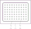
In a manufacturing process of a liquid crystal panel, one of methods for forming a liquid crystal layer is a method called an one drop filling method (ODF). This method is a method in which a liquid crystal material is dropped to one of 2 substrates to be bonded in a fixed amount before bonding, and then bonding is performed in vacuum.
The liquid crystal material is dropped onto the substrate 71 by arranging a plurality of droplets (droplets 72) of the liquid crystal material in a matrix so that the liquid crystal material is contained in a frame of a sealing material 73 formed in a rectangular frame shape for blocking the liquid crystal material (see fig. 7). Basically, the droplets are dropped one by one dropping device, but a plurality of droplets may be dropped simultaneously in order to increase the processing speed. For example, the following devices are available as a discharge device that simultaneously discharges a plurality of droplets by one device.
Documents of the prior art
Patent document
Patent document 1: japanese patent laid-open No. 2007-167844
Patent document 2: japanese patent laid-open No. 2003-25565
Disclosure of Invention
Problems to be solved by the invention
In the prior art, when a plurality of droplets are simultaneously coated by using a dripping device with a plurality of nozzles, the nozzle part itself with the nozzles arranged needs to be exchanged in order to change the distance between the dripping points and the shape of the coating pattern, but the exchange of the nozzle part itself is difficult. On the other hand, if the nozzle part itself is not exchanged and the coating is performed by dropping, the quality may be greatly affected. In particular, when liquid crystal droplets are applied in a matrix form so that the liquid crystal material is accommodated in a frame of a sealing material formed in a rectangular frame shape for blocking the liquid crystal material, if the distance between the droplet-dropping points or the pattern shape cannot be easily changed, and if the size of the frame of the sealing material varies, the distance between the sealing material and the liquid crystal droplets cannot be appropriately maintained, which may cause a problem of uneven diffusion of the liquid crystal at the time of bonding.
If the nozzle itself is deformed as in patent document 2, discharge conditions differ between the nozzles, and there is a problem that highly accurate coating cannot be performed with respect to the amount and position.
Accordingly, an object of the present invention is to provide a liquid material dripping device and method capable of easily changing the distance between dripping points when multi-point simultaneous coating is performed.
Means for solving the problems
The present invention relates to a dripping device, characterized in that: the liquid material metering device is provided with a metering part for metering a liquid material, a plunger reciprocating in the metering part, a nozzle part provided with a plurality of nozzles having discharge ports, a supply flow path for supplying the liquid material to the metering part, and a switching valve for switching communication between the metering part and the nozzle part and between the metering part and the supply flow path.
The dropping device may be characterized in that: the nozzle comprises n2(n is a natural number of 2 or more) nozzles, and the number of nozzles may be: the nozzle unit is configured such that the discharge port of the nozzle is directed outward with respect to the center of the nozzle unit in the vertical directionThe nozzle may be disposed in the nozzle portion, or the nozzle may be disposed in the nozzle portion such that a discharge port of the nozzle faces inward with respect to a center of the nozzle in a vertical direction.
The dropping device may be characterized in that: the nozzle portion includes a nozzle block having a single inflow channel and a branch channel connecting the inflow channel and the discharge port, and the nozzle is attached to the nozzle block.
The present invention relates to a coating apparatus, characterized in that: the disclosed device is provided with: the dropping device described above; a workpiece stage on which a substrate is placed; an XYZ driving device that moves the dropping device and the workpiece stage relative to each other; and a control unit having a storage device.
In the above coating apparatus, the coating apparatus may further include: the present invention is characterized by comprising a plurality of the above-described dropping devices, wherein the number of nozzles, the interval of nozzles, or the angle θ of nozzles of one dropping device is different from the interval of nozzles or the angle θ of nozzles of another dropping device, or by comprising a plurality of the above-described dropping devices, and the number of nozzles, the interval of nozzles, and the angle θ of nozzles of all the dropping devices are the same.
The present invention relates to a dropping method using the above-described coating apparatus, and the dropping method is characterized in that: the distance (L1, L2) between the dropping points of the droplets discharged from the nozzle is adjusted by adjusting the vertical distance between the workpiece stage and the dropping device based on an input value, and the liquid material is dropped onto the workpiece while relatively moving the dropping device and the workpiece stage in the horizontal direction while keeping the vertical distance between the workpiece stage and the dropping device constant.
The dropping method may be characterized in that: a correlation model of a vertical distance between the plurality of work stages and the dropping device and a distance (L1, L2) between dropping points of the droplets is stored in a storage device of the control unit, and the input value is a selection value of the correlation model.
The present invention, which is a dropping method from another viewpoint, is a dropping method using a coating apparatus, the coating apparatus being characterized in that: the method for dropping a liquid crystal material, which comprises a plurality of dropping devices, wherein the number of nozzles, the nozzle interval, and the nozzle angle θ of all the dropping devices are the same, is characterized in that: the same one drop coating is performed by all of the plurality of drop coating devices, thereby performing multiple coating. Here, the following may be also featured: the workpiece is a liquid crystal panel substrate, and the liquid material is liquid crystal.
Effects of the invention
According to the present invention, when multi-point simultaneous coating is performed, the distance between the dropping points can be easily changed.
Drawings
Fig. 1 is a schematic side view of a dripping device according to embodiment 1.
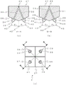
FIG. 2(a) is a bottom view of a nozzle unit used in the dripping device according to embodiment 1, (B) is a sectional view taken along line A-A, and (c) is a sectional view taken along line B-B.
Fig. 3 is an explanatory view for explaining a relationship between a dropping height and a distance between dropping points when dropping is performed using the dropping device according to embodiment 1. (a) A plan view showing the dropping height Ha, (b) a plan view showing the dropping height Hb, and (c) a plan view showing the dropping height Hc.
Fig. 4 is a schematic perspective view of the coating apparatus according to embodiment 1.
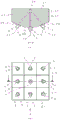
FIG. 5(a) is a bottom view of the nozzle unit according to embodiment 2, (b) is a sectional view taken along the line C-C, and (C) is a sectional view taken along the line D-D.
Fig. 6(a) is a bottom view of the nozzle unit according to embodiment 3, and (b) is a cross-sectional view taken along line E-E.
Fig. 7 is an explanatory view for explaining a state when a liquid is dropped onto a substrate in a manufacturing step of a liquid crystal panel.
Detailed Description
Hereinafter, embodiments for carrying out the present invention will be described.
EXAMPLE 1 embodiment
The dripping device 1 according to embodiment 1 includes 4 nozzles 4 arranged at equal intervals from the center in the vertical direction of the nozzle unit 6, and the distance between the nozzle 4 and the substrate 46 is adjusted to adjust the distance between the 4 dripping points which land on the substrate 46. The dripping device 1 is attached to an application device 51 having XYZ drive devices (52, 53, 54), and performs an application operation while relatively moving with respect to a workpiece table on which an object to be applied is placed.
The structure and operation of the dripping device 1 and the coating device 51 will be described in detail below.
< dropping device >
Fig. 1 is a schematic side view showing a dropping device 1 according to embodiment 1.
The dripping device 1 according to embodiment 1 is a plunger type dripping device, and includes: a tubular metering section 2; a plunger 3 internally connected to the metering section 2; a nozzle section 6 having a plurality of nozzles 4; a switching valve 7 for switching communication between the metering section 2 and the nozzle section 6 and between the metering section 2 and the supply passage 15; and a side-view L-shaped body 9 in which a plunger drive device is built.
The measuring portion 2 has a measuring hole as a cylindrical space therein, and the plunger 3 is slidably inserted into the measuring hole.
The plunger 3 is a rod-shaped member having a large diameter portion 8 at an end portion thereof, and the end portion opposite to the large diameter portion 8 is inserted into the measuring portion 2. The plunger 3 is held in the vicinity of the large diameter portion 8 by a plunger driving means 10, and is movable in the direction indicated by reference numeral 11 by a plunger driving means for moving the plunger driving means 10. By sliding the plunger 3 in close contact with the inner wall of the measuring section 2, the liquid 19 can be sucked into the measuring section 2 or the liquid 19 can be pushed out from the measuring section 2.
The switching valve 7 includes a flow path a12 communicating with the supply flow path 15, a flow path B13 communicating with the metering section 2, and a flow path C14 communicating with the nozzle section 6, and can selectively switch between a first position where the supply flow path 15 communicates with the metering section 2 and a second position where the metering section 2 communicates with the nozzle section 6. The switching valve 7 may be configured as a rotary valve or a spool valve. Further, the flow path B13 and the flow path C14 are preferably arranged in the same direction as the plunger moving direction (reference numeral 11). This is to transmit the force generated by the plunger 3 to the liquid 19 without waste at the time of discharge.
The supply channel 15 is a channel communicating with a liquid pipe 18 for supplying a liquid 19 stored in the container 17, and is provided inside the extension member 16. The extension member 16 is fixed to the body 9 so that the supply passage 15 and the passage a12 communicate with each other in an airtight manner. A bubble removal mechanism 20 is provided between the supply channel 15 and the liquid pipe 18. As the bubble removing means 20, for example, a means having a1 st flow path communicating with the liquid material supply portion side, a 2 nd flow path communicating with the measuring portion side, and a main body communicating with the 1 st flow path and the 2 nd flow path and having a width wider than that of the 1 st flow path, and having a discharge port of the 1 st flow path arranged at a position above a suction port of the 2 nd flow path, can be used (refer to patent No. 4898778 of the applicant). The bubble removal mechanism 20 may not be provided.
A working gas supply pipe 23 for supplying a working gas for pumping the liquid 19 is connected to the container 17 for storing the liquid 19.
The main body 9 is attached to a base plate 25, and a container support member 24 for fixing the container 17 is attached to an upper portion of the base plate 25. The base plate 25 is attached to a connecting member 26 for connecting to XYZ driving devices (52, 53, 54) or a fixed bracket, which will be described later.
< nozzle section >
FIG. 2 is a bottom view, a cross-sectional view taken along line A-A and a cross-sectional view taken along line B-B, respectively, of a nozzle unit 6 used in the dripping device according to embodiment 1.
The nozzle section 6 of embodiment 1 is configured to include a nozzle block 27 having a pentagonal cross section and 4 nozzles 4 arranged on a nozzle connection surface 28 which is a lower surface of the nozzle block 27. The nozzle portion 6 is detachably mounted on the lower surface of the body 9.
For convenience of explanation, the nozzles A to D (34 to 37) are referred to as 4 nozzles 4, and the discharge ports A to D (38 to 41) are referred to as the discharge ports 5 of the 4 nozzles.
An inflow channel 29 communicating with a channel C14 of the dripping device 1 and branched channels A to D (30 to 33) branched from the inflow channel 29 to the nozzles A to D (34 to 37) are formed in the nozzle block 27.
The inclined surface, i.e., the lower surface, of the nozzle block 27 is divided into 4 blocks, and one nozzle 4 (reference numerals 34 to 37) is mounted in each block. In embodiment 1, as shown in FIG. 2As shown, the nozzle connection surface 28 is formed by arranging 4 square planes of the same size with the center of the lower surface as the apex. That is, the nozzle block 27 has a square shape when viewed from the bottom surface. The number of blocks on the lower surface of the nozzle block 27 is not limited to the exemplified number of blocks, and any number of blocks such as 2 to 16 can be set, but preferably the number of blocks is n2(n is a natural number of 2 or more). Preferably, the number of blocks on the lower surface of the nozzle block 27 is set to be the same as the number of nozzles 4.
The nozzles 4 attached to the inclined surface are arranged at equal intervals so as to be square when viewed from the bottom surface. That is, the nozzles a34, B35, C36, and D37 are arranged in a matrix. Regardless of which nozzle 4 is selected, the spacing of one nozzle 4 from the adjacent other nozzles 4 is the same.
Each nozzle 4 has one discharge port, and the discharge port central axis 43 is attached so as to be perpendicular to the nozzle connection surface 28. In embodiment 1, since each of the nozzle connection surfaces 28 is inclined at a predetermined angle with respect to the vertical axis 42 of the nozzle block 27, the discharge ports a to D (38 to 41) face outward with respect to the center in the vertical direction of the nozzle block 27. The inclination angles of the respective faces of the nozzle connection face 28 are uniform. That is, θ a, θ b, θ c, and θ d shown in fig. 2 are all the same (θ a — θ b — θ c — θ d). In other words, the angle θ (for example, 5 to 60 degrees) formed by one nozzle 4 and the vertical line is the same for any selected nozzle 4.
The discharge ports A to D (38 to 41) are arranged so as to face the respective corners of the nozzle block 27. That is, the discharge ports a to D (38 to 41) are arranged on the diagonal line of the bottom surface 28 (see fig. 2 c). Thus, the quadrangle formed by connecting the 4 droplets 45 discharged from the discharge ports A to D (38 to 41) is a quadrangle having a shape similar to the arrangement of the nozzles A to D (34 to 37) of the nozzle block 27. The branched flow paths A to D (30 to 33) are preferably formed coaxially with the central axes (discharge port central axes 43) of the nozzles A to D (34 to 37) so that the discharge of the liquid 19 can be performed smoothly.
< discharge action >
The discharge operation of the dropping device 1 described above is summarized as follows.
(1) Preparation (initial filling step)
First, the liquid 19 is filled up to the upper end of the measuring portion 2 without inserting the plunger 3 into the measuring portion 2. The plunger 3 is then inserted into the metering section 2 and fixed to the plunger drive member 10. Subsequently, the metering section 2 and the nozzle section 6 are communicated with each other by the switching valve 7, and the plunger 3 is moved from the discharge port 5 toward the nozzle section 6 (the inlet direction) until the liquid 19 is discharged.
(2) Discharge step
The metering section 2 and the nozzle section 6 are communicated with each other by the switching valve 7, and the plunger 3 is moved at high speed in the intake direction, whereby the same amount of liquid 19 is ejected and discharged from the 4 discharge ports 5.
(3) Suction step
The supply channel 15 and the measuring section 2 are communicated with each other by the switching valve 7, and the plunger 3 is moved in a direction (backward direction) opposite to the entering direction to suck the liquid 19 into the measuring section 2.
By repeating the steps (2) and (3), a continuous and constant-volume discharge coating operation can be performed. In addition, the steps (2) and (3) may be started either first.
< adjustment of distance between dropping points >
Fig. 3 is an explanatory view showing a relationship between the height (H) of the nozzle portion 6 and the distance (L) between the dropping points when dropping is performed using the dropping device 1 of embodiment 1. In fig. 3, the upper view shows a side view, and the lower view shows a top view of the substrate 46. Fig. 3 schematically illustrates only the nozzle portion 6.
Since the nozzle 4 is inclined at a predetermined angle, the liquid droplets 45 discharged from the discharge port 5 of the nozzle 4 reach the substrate 46 as the coating surface while drawing the parabolic flight path 44. Since the 4 nozzles 4 arranged at equal intervals from the center of the nozzle portion 6 are inclined radially and uniformly, the liquid droplets 45 applied to the substrate 46 form a rectangular pattern arranged at the corners of a square. That is, as shown in the lower side of fig. 3, the longitudinal dropping point distance (L1) is the same as the lateral dropping point distance (L2) (L1 — L2).
Since the nozzle 4 is inclined at a predetermined angle to draw the parabolic flight trajectory 44, the distance between the nozzle 6 (discharge port 5) and the substrate 46 (in other words, the height (H) of the nozzle 6) is changed, that is, the distance between the vertical and horizontal dropping points (L1, L2) can be changed.
Here, the (b) drawn in the center is used as a reference. (b) In the case of (3), when the distance from the substrate 46 to the discharge port 5 is Hb, the drop point distance in the vertical direction is L1b, and the drop point distance in the horizontal direction is L2 b. When the nozzle unit 6 is lowered as in (a), the droplet 45 reaches the substrate 46 before expanding in a parabolic shape, and therefore the distance between the dropping points becomes shorter (La < Lb) as compared with the case of (b).
On the other hand, when the nozzle unit 6 is raised as in (c), the droplet 45 reaches the substrate 46 after expanding in a parabolic shape, and therefore the distance between the dropping points becomes longer (Lc > Lb) as compared with the case of (b).
Since each nozzle 4 is inclined at a predetermined angle in this manner, the distance between the dropping points in the vertical and horizontal directions (L1, L2) can be changed by changing the height (H) of the nozzle section 6.
The relationship with the inclination (θ) of the nozzle 4, the height (H) of the nozzle portion 6, and the vertical and horizontal distances (L1, L2) between the dropping points may be prepared as a table or a graph in advance by experiments, and stored in advance in a storage device of a control unit (not shown). With this configuration, the desired distance between the drip points (L1, L2) in the vertical and horizontal directions can be easily realized by changing the setting based on a table or a graph displayed on a display device (not shown). According to the experiment of the inventors, for example, when the nozzle 4 is tilted by 10 degrees, the distances between the dropping points (L1, L2) are each 7.5mm when the nozzle is discharged from a height of 15mm, the distances between the dropping points (L1, L2) are each 6.5mm when the nozzle is discharged from a height of 10mm, and the distances between the dropping points (L1, L2) are each 8.5mm when the nozzle is discharged from a height of 20 mm.
< coating apparatus >
Fig. 4 is a schematic perspective view of an application device 51 including the dripping device 1 according to embodiment 1.
The coating device 51 of the embodiment mainly includes: a Z-axis drive unit 54 for moving the dripping unit 1 in the vertical direction (indicated by reference numeral 57); an X-axis drive unit 52 to which a Z-axis drive unit 54 is attached and which is movable in the left-right direction (indicated by reference numeral 55); a Y-axis drive device 53 capable of moving the beam 61 provided with the X-axis drive device 52 in the front-rear direction (reference numeral 56); a workpiece stage 58 on which the substrate 46 is placed; a mount 63 on which the driving devices (52, 53, 54) and the workpiece stage 58 are disposed; and a control unit not shown. The coating apparatus 51 can perform the following dropping method: the vertical distance between the workpiece stage 58 and the dropping device 1 is adjusted by the control unit based on the input value of the user, and the distance between the dropping points of the droplets discharged from the nozzles 4 is adjusted (L1, L2), so that the liquid material is dropped while relatively moving the dropping device 1 and the workpiece stage 58 in the horizontal direction after the vertical distance between the workpiece stage 58 and the dropping device 1 is kept constant. The dropping point to be dropped on the workpiece is set by a row of m1 columns × m2 rows, and preferably, either m1 or m2 is set to a multiple of the number n of nozzles (natural number).
The X-axis drive device 52 is provided with an X-axis slider 59 interposed therebetween, and the Z-axis drive device 54 and the dropping device 1 can be moved. Further, Y sliders 60 are provided inside the Y-axis drive devices 53, respectively, and a beam 61 on which the X-axis drive device 52 is provided is supported by a beam support member 62 to move. By configuring the XYZ driving device as described above, the dropping device 1 can be moved relative to the substrate 46. In the present invention, it is preferable to adopt, as the XYZ driving device, a mechanism that adjusts the distance between the dropping points (L1, L2) by adjusting the position of the discharge port in the vertical direction (Z direction), and thus can perform positioning in the Z direction with high accuracy. As such an XYZ drive device, a combination mechanism of a ball screw and a motor, a mechanism using a linear motor, a mechanism for transmitting power by a belt, a bar, or the like can be used.
In the present embodiment, the driving device is configured as a so-called overhead type, but any configuration may be used as long as the dropping device 1 and the substrate 46 (the work stage 58) can be moved relative to each other. For example, the X-axis drive device 52 and the Y-axis drive device 53 may be provided below the workpiece table 58.
In embodiment 1, a configuration in which 4 dropping devices 1 are provided is exemplified, but the number of the devices provided is not limited to these, and may be 1, 2, 3, or the like.
In the configuration in which a plurality of dropping devices 1 are provided, there are a case in which all the dropping devices 1 of the same kind are set, and a case in which different kinds of dropping devices 1 are combined. When a plurality of the same dropping device 1 are provided, so-called multi-coating in which a plurality of panels are formed in the substrate 46 can be applied. In the case of combining different types of dripping devices 1 (for example, in the case of providing a nozzle unit 6 in which the inclination angle of the nozzle 4 is changed for each dripping device 1), the distance between the dripping points (L1, L2) can be adjusted more variously than in the case of one type of dripping device 1.
According to the coating apparatus 51 of embodiment 1 described above, when performing multi-point simultaneous coating of several tens or more, the distance between the dropping points (L1, L2) can be easily changed. In particular, in the One Drop Fill (ODF) method, the coating device 51 can keep the liquid crystal spread uniformly at all times by appropriately keeping the distance between the liquid crystal drop and the sealing material formed in a rectangular frame shape for blocking the liquid crystal material.
EXAMPLE 2 EXAMPLE
Fig. 5 shows a bottom view of the nozzle unit 6 used in the dripping device 1 according to embodiment 2, a cross-sectional view taken along the line C-C, and a cross-sectional view taken along the line D-D, respectively. In the following description, the same portions as those of embodiment 1 (portions other than the nozzle portion 6) will not be described, and only different portions will be described.
The nozzle unit 6 of embodiment 2 is different from embodiment 1 in that the nozzles are arranged such that the discharge ports (38 to 41) of the 4 nozzles (34 to 37) face inward (toward the center of the nozzle unit 6).
In embodiment 2, the 4 planes constituting the nozzle connection surface 28 are inclined at a predetermined angle with respect to the vertical axis 42 of the nozzle block 27 so that the center of the nozzle portion 6 becomes the innermost surface in a bottom view. That is, the discharge ports A to D (38 to 41) of the nozzles A to D (34 to 37) are vertical shafts 42 facing the nozzle block 27 when viewed from the bottom.
The point where the inflow channel 29 communicating with the channel C14 of the dripping device 1 and the branch channels a to D (30 to 33) branching from the inflow channel 29 to the nozzles a to D (34 to 37) are formed in the nozzle block 27 is the same as in embodiment 1. However, points where the branched flow paths a to D (30 to 33) are formed by being bent are different from those of embodiment 1. That is, the branched flow paths a to D (30 to 33) have flow paths formed in upstream portions communicating with the inflow flow path 29 in a direction radiating from the vertical axis 42, flow paths coaxial with the discharge port central axes 43 of the nozzles a to D (34 to 37) are formed in downstream portions communicating with the nozzles a to D (34 to 37), and the upstream portions and the downstream portions are connected via a bent portion.
In embodiment 2, the distance between the nozzle and the substrate is also adjusted, whereby the distance between the 4 dropping points dropped on the substrate can be adjusted (L1, L2). Since the discharge ports (38-41) of the 4 nozzles (34-37) are directed inward in embodiment 2, the adjustment of the distances between the dropping points (L1, L2) is more suitable than in embodiment 1.
EXAMPLE 3
Fig. 6 is a bottom view and a cross-sectional view taken along line E-E of the nozzle unit 6 used in the dripping device 1 according to embodiment 3. In the following description, the same portions as those of embodiment 1 (portions other than the nozzle portion 6) will not be described, and only different portions will be described.
The nozzle unit 6 according to embodiment 3 is the same as that of embodiment 1 in that the square nozzles 4 are arranged in a matrix, but is different from that of embodiment 1 in that the number of nozzles 4 is 9. In the nozzle unit 6 according to embodiment 3, the nozzle connection surface 28, which is the lower surface of the nozzle block 27, is divided into 9 blocks, and one nozzle 4 is attached to each block. The 9 blocks constituting the nozzle connection surface 28 are formed of rectangular planes having the same size, and are arranged such that the center of the lower surface is a vertex. Wherein, the central block is horizontally arranged. The 8 blocks other than the center are inclined at a predetermined angle with respect to the vertical axis 42 of the nozzle block 27 so that the discharge ports 5 of the nozzles 4 face outward. The angles are made uniform so that the applied droplets 45 are disposed at the corners or the midpoints of the sides of the quadrangle.
The nozzle block 27 is square when viewed from the bottom. The 8 nozzles 4 other than the center are arranged at the center or the vertex of the side of the small square viewed in elevation around the nozzle block 27. A nozzle 4 located at the center is arranged at the intersection of the diagonal lines of the square. That is, the nozzles 4 adjacent in the horizontal direction are equidistant.
In embodiment 3, the nozzle portion 6 is constituted by 9 nozzles 4, but the number of nozzles 4 is not limited to this, and n may be used2The nozzles (n is a natural number of 2 or more) constitute the nozzle unit 6. That is, for example, by setting the number of nozzles 4 to a square of 2 or more (i.e., 4, 9, 16, 25, 36 …), the distance between the dropping points (L1, L2) can be uniformly adjusted while maintaining the matrix-like dropping pattern.
In embodiment 3 as well, the distance between the nozzle and the substrate can be adjusted to adjust the distance between 9 dropping points dropped on the substrate (L1, L2). In embodiment 3, since 9 drops can be simultaneously performed, productivity can be improved as compared with embodiment 1.
Description of the symbols
1 dripping device
2 measuring part
3 plunger piston
4 nozzle
5 discharge port
6 nozzle part
7 switching valve
8 big diameter part
9 main body
10 plunger drive member
11 direction of plunger movement
12 flow path A
13 flow path B
14 flow channel C
15 supply flow path
16 extension member
17 Container
18 liquid piping
19 liquid
20 bubble removing mechanism
21 stream of liquid
22 stream of gas
23 working gas supply pipe
24 Container support Member
25 base plate
26 connecting member
27 nozzle block
28 nozzle connecting surface
29 inflow channel
30 branched flow paths A
31 branched flow path B
32 branched flow path C
33 divergent flow path D
34 nozzle A
35 nozzle B
36 nozzle C
37 nozzle D
38 discharge opening A
39 discharge port B
40 discharge port C
41 discharge port D
42 vertical axis of nozzle block
43 center axis of discharge port
44 flight path
45 liquid droplet
46 substrate (coating surface)
47 divergent flow path
51 coating device
52X-axis driving device
53Y-axis driving device
54Z-axis driving device
55X moving direction (left and right direction)
56Y moving direction (front and back direction)
57Z moving direction (Up-down direction)
58 workpiece table
59X-axis sliding block
60Y-axis sliding block
61 Beam
62 Beam support Member
63 stand
71 substrate
72 droplet
73 sealing material
Claims (18)
1. A dripping device is characterized in that a dripping device is arranged,
comprises a metering section for metering a liquid material, a plunger reciprocating in the metering section, a nozzle section having a plurality of nozzles with discharge ports, a supply passage for supplying the liquid material to the metering section, and a switching valve for switching communication between the metering section and the nozzle section and between the metering section and the supply passage,
the nozzle unit is configured such that a plurality of dots can be simultaneously applied in a matrix pattern, the nozzles are arranged in a matrix pattern when viewed from the bottom surface so that the intervals between one nozzle and an adjacent nozzle are the same, and the plurality of inclined nozzles are arranged in an inclined manner so that the angles theta formed by the plurality of inclined nozzles among the nozzles and the vertical line are the same,
the nozzle unit is arranged such that the discharge ports of the plurality of inclined nozzles face outward or inward with respect to the center of the nozzle unit in the vertical direction.
2. Dripping apparatus according to claim 1,
the nozzles are arranged in a rectangular frame in a matrix shape when viewed from the bottom.
3. Dripping apparatus according to claim 2,
the nozzle is composed of n2Wherein n is a natural number of 2 or more.
4. Dripping apparatus according to claim 2,
the nozzles are arranged such that the discharge ports of the nozzles are all directed outward with respect to the center in the vertical direction of the nozzle.
5. Dripping apparatus according to claim 2,
the nozzles are arranged such that the discharge ports of the nozzles are all directed inward with respect to the center in the vertical direction of the nozzle.
6. Dripping apparatus according to claim 3,
the nozzles are constituted by an even number of nozzles,
all of the nozzles are arranged obliquely in a square frame when viewed from the bottom.
7. Dripping apparatus according to claim 3,
the nozzles are formed of an odd number of nozzles,
the nozzles outside the center are arranged obliquely in a square frame when viewed from the bottom,
the nozzle located at the center is disposed at the intersection of the diagonal lines of the square frame when viewed from the bottom.
8. Dripping apparatus according to any of claims 1 to 7,
the nozzle portion includes a nozzle block having a single inflow channel and a branch channel connecting the inflow channel and the discharge port, and the nozzle is attached to the nozzle block.
9. A coating device is characterized in that a coating device is provided,
the disclosed device is provided with:
the dripping apparatus of claim 1;
a workpiece stage on which a substrate is placed;
an XYZ driving device which moves the dripping device and the workpiece table relatively; and
and a control unit having a storage device.
10. A coating apparatus as in claim 9,
the number of nozzles, the interval of nozzles, or the angle θ of nozzles in one dripping device is different from the interval of nozzles or the angle θ of nozzles in another dripping device.
11. A coating apparatus as in claim 9,
the number of nozzles, the nozzle interval, and the nozzle angle θ of all the dropping devices are the same.
12. A coating apparatus as in claim 9,
the control unit adjusts a vertical distance between the workpiece stage and the dropping device based on an input value, thereby adjusting distances (L1, L2) between dropping points of the droplets discharged from the nozzle, and drops the liquid material onto the workpiece while relatively moving the dropping device and the workpiece stage in a horizontal direction while maintaining the vertical distance between the workpiece stage and the dropping device at a constant value.
13. A coating apparatus as in claim 12,
a correlation model between the vertical distance between the plurality of work stages and the dropping device and the distance (L1, L2) between the dropping points of the droplets is stored in the storage device of the control unit,
the input value is a selection value of the correlation model.
14. A dripping method is characterized in that,
with the use of the coating apparatus according to claim 12,
the distance (L1, L2) between the dropping points of the droplets discharged from the nozzle is adjusted by adjusting the vertical distance between the workpiece stage and the dropping device based on an input value, and the liquid material is dropped onto the workpiece while relatively moving the dropping device and the workpiece stage in the horizontal direction while keeping the vertical distance between the workpiece stage and the dropping device constant.
15. The dripping method according to claim 14 wherein,
a correlation model between the vertical distance between the plurality of work stages and the dropping device and the distance (L1, L2) between the dropping points of the droplets is stored in the storage device of the control unit,
the input value is a selection value of the correlation model.
16. A dripping method is characterized in that,
with the use of the coating apparatus as claimed in claim 11,
the same one drop coating is performed by all of the plurality of drop coating devices, thereby performing multiple coating.
17. The dripping method according to claim 16 wherein,
the work includes a rectangular frame onto which a liquid material is dropped.
18. The dripping method according to claim 16 wherein,
the workpiece is a liquid crystal panel substrate, and the liquid material is liquid crystal.
Applications Claiming Priority (3)
| Application Number | Priority Date | Filing Date | Title |
|---|---|---|---|
| JP2014-117925 | 2014-06-06 | ||
| JP2014117925A JP6389379B2 (en) | 2014-06-06 | 2014-06-06 | Liquid material dropping apparatus and method |
| PCT/JP2015/066051 WO2015186743A1 (en) | 2014-06-06 | 2015-06-03 | Liquid material dropping device and method |
Publications (2)
| Publication Number | Publication Date |
|---|---|
| CN106461989A CN106461989A (en) | 2017-02-22 |
| CN106461989B true CN106461989B (en) | 2021-01-12 |
Family
ID=54766812
Family Applications (1)
| Application Number | Title | Priority Date | Filing Date |
|---|---|---|---|
| CN201580030173.0A Active CN106461989B (en) | 2014-06-06 | 2015-06-03 | Liquid material dripping device and method |
Country Status (6)
| Country | Link |
|---|---|
| JP (1) | JP6389379B2 (en) |
| KR (1) | KR102328887B1 (en) |
| CN (1) | CN106461989B (en) |
| HK (1) | HK1231567A1 (en) |
| TW (2) | TWI717320B (en) |
| WO (1) | WO2015186743A1 (en) |
Families Citing this family (2)
| Publication number | Priority date | Publication date | Assignee | Title |
|---|---|---|---|---|
| JP6745683B2 (en) * | 2016-08-31 | 2020-08-26 | Ntn株式会社 | Liquid coating unit, liquid coating device, and liquid coating method |
| CN107300811B (en) * | 2017-08-11 | 2020-11-20 | 京东方科技集团股份有限公司 | Liquid crystal dripping nozzle, liquid crystal dripping device and liquid crystal dripping method |
Citations (4)
| Publication number | Priority date | Publication date | Assignee | Title |
|---|---|---|---|---|
| CN1548247A (en) * | 2003-05-19 | 2004-11-24 | 乐金电子(沈阳)有限公司 | Ink jetting coating unit for making display board |
| CN1700044A (en) * | 2004-05-19 | 2005-11-23 | 精工爱普生株式会社 | Method of manufacturing color filter substrate, method of manufacturing electro-optical device, electro-optical device, and electronic apparatus |
| CN102006943A (en) * | 2008-02-21 | 2011-04-06 | 武藏工业株式会社 | Device and method for discharging liquid material |
| CN102019256A (en) * | 2009-08-26 | 2011-04-20 | 卡西欧计算机株式会社 | Application device and method of producing application layer using same |
Family Cites Families (11)
| Publication number | Priority date | Publication date | Assignee | Title |
|---|---|---|---|---|
| JP3436785B2 (en) * | 1994-01-25 | 2003-08-18 | 芝浦メカトロニクス株式会社 | Substrate cleaning equipment |
| JPH10263467A (en) * | 1997-03-25 | 1998-10-06 | Nichiha Corp | Coating of building panel and apparatus therefor |
| JP2003507198A (en) * | 1999-08-18 | 2003-02-25 | コーニンクレッカ フィリップス エレクトロニクス エヌ ヴィ | Method of forming a pattern of recesses or holes in a plate |
| JP2003025565A (en) | 2001-07-11 | 2003-01-29 | Sharp Corp | Line head and printer comprising it |
| JP2004145090A (en) * | 2002-10-25 | 2004-05-20 | Seiko Epson Corp | Apparatus and method for manufacturing liquid crystal display device |
| JP2006272292A (en) * | 2005-03-30 | 2006-10-12 | Matsushita Electric Ind Co Ltd | Viscous fluid applying apparatus |
| US20070145164A1 (en) * | 2005-12-22 | 2007-06-28 | Nordson Corporation | Jetting dispenser with multiple jetting nozzle outlets |
| US20080062376A1 (en) * | 2006-09-12 | 2008-03-13 | United Microdisplay Optronics Corp. | Method of fabricating a liquid crystal panel and alignment method |
| JP5244366B2 (en) * | 2007-10-30 | 2013-07-24 | 武蔵エンジニアリング株式会社 | Liquid material dripping method, program and apparatus |
| JP2009291684A (en) * | 2008-06-03 | 2009-12-17 | Fujifilm Corp | Method of forming functional film pattern |
| JP2010194399A (en) * | 2009-02-23 | 2010-09-09 | Fuji Xerox Co Ltd | Liquid droplet discharge head and liquid droplet discharge device |
-
2014
- 2014-06-06 JP JP2014117925A patent/JP6389379B2/en active Active
-
2015
- 2015-06-03 WO PCT/JP2015/066051 patent/WO2015186743A1/en active Application Filing
- 2015-06-03 CN CN201580030173.0A patent/CN106461989B/en active Active
- 2015-06-03 KR KR1020167031980A patent/KR102328887B1/en active IP Right Grant
- 2015-06-05 TW TW104118291A patent/TWI717320B/en active
- 2015-06-05 TW TW109116267A patent/TWI718061B/en active
-
2017
- 2017-05-18 HK HK17105021.3A patent/HK1231567A1/en unknown
Patent Citations (4)
| Publication number | Priority date | Publication date | Assignee | Title |
|---|---|---|---|---|
| CN1548247A (en) * | 2003-05-19 | 2004-11-24 | 乐金电子(沈阳)有限公司 | Ink jetting coating unit for making display board |
| CN1700044A (en) * | 2004-05-19 | 2005-11-23 | 精工爱普生株式会社 | Method of manufacturing color filter substrate, method of manufacturing electro-optical device, electro-optical device, and electronic apparatus |
| CN102006943A (en) * | 2008-02-21 | 2011-04-06 | 武藏工业株式会社 | Device and method for discharging liquid material |
| CN102019256A (en) * | 2009-08-26 | 2011-04-20 | 卡西欧计算机株式会社 | Application device and method of producing application layer using same |
Also Published As
| Publication number | Publication date |
|---|---|
| JP6389379B2 (en) | 2018-09-12 |
| KR102328887B1 (en) | 2021-11-18 |
| CN106461989A (en) | 2017-02-22 |
| KR20170015289A (en) | 2017-02-08 |
| TWI718061B (en) | 2021-02-01 |
| WO2015186743A1 (en) | 2015-12-10 |
| TWI717320B (en) | 2021-02-01 |
| TW202035028A (en) | 2020-10-01 |
| JP2015230458A (en) | 2015-12-21 |
| HK1231567A1 (en) | 2017-12-22 |
| TW201607613A (en) | 2016-03-01 |
Similar Documents
| Publication | Publication Date | Title |
|---|---|---|
| TWI692379B (en) | Coating device and coating method | |
| JP5340181B2 (en) | Liquid material discharge apparatus and method | |
| US10011121B2 (en) | Printing on cylindrical objects | |
| KR102492633B1 (en) | Liquid material application method and apparatus for carrying out the method | |
| CN106461989B (en) | Liquid material dripping device and method | |
| WO2015046481A1 (en) | Droplet material discharge device, coating device provided with same liquid material discharge device, and coating method using same coating device | |
| JP2017527436A (en) | Valve seat for dispenser | |
| JP6243278B2 (en) | Coating liquid coating apparatus and method | |
| JP2015230458A5 (en) | ||
| US11975494B2 (en) | Nozzle and applicator system for fabric bonding |
Legal Events
| Date | Code | Title | Description |
|---|---|---|---|
| C06 | Publication | ||
| PB01 | Publication | ||
| SE01 | Entry into force of request for substantive examination | ||
| SE01 | Entry into force of request for substantive examination | ||
| REG | Reference to a national code |
Ref country code: HK Ref legal event code: DE Ref document number: 1231567 Country of ref document: HK |
|
| GR01 | Patent grant | ||
| GR01 | Patent grant |