CN103465145A - Five-axis numerical control polishing machine capable of changing grinding heads automatically - Google Patents
Five-axis numerical control polishing machine capable of changing grinding heads automatically Download PDFInfo
- Publication number
- CN103465145A CN103465145A CN2013103919102A CN201310391910A CN103465145A CN 103465145 A CN103465145 A CN 103465145A CN 2013103919102 A CN2013103919102 A CN 2013103919102A CN 201310391910 A CN201310391910 A CN 201310391910A CN 103465145 A CN103465145 A CN 103465145A
- Authority
- CN
- China
- Prior art keywords
- axis
- bistrique
- guide rail
- axle
- numerical control
- Prior art date
- Legal status (The legal status is an assumption and is not a legal conclusion. Google has not performed a legal analysis and makes no representation as to the accuracy of the status listed.)
- Granted
Links
Images


Abstract
The invention discloses a five-axis numerical control polishing machine capable of changing grinding heads automatically. The five-axis numerical control polishing machine comprises a plurality of semi-axis grinding heads, a machine body frame, a controller, a polishing head, a grinding head supply mechanism, a spindle clamping device, a Z-axis drive mechanism, an X-axis drive mechanism, a Y-axis drive mechanism, an A-axis rotary workbench and a C-axis rotating mechanism. The polishing head, the grinding head supply mechanism, the spindle clamping device, the Z-axis drive mechanism, the X-axis drive mechanism, the Y-axis drive mechanism, the A-axis rotary workbench and the C-axis rotating mechanism are respectively connected with the controlled and controlled by the same. The five-axis numerical control polishing machine capable of changing grinding heads automatically has the advantages that the polishing machine is ingenious and reasonable in structural design, high in automation level, convenient and fast to operate, high in flexibility by the five-axis linkage structure, and widely applicable; multiple polishing procedures such as rough polishing, fine polishing and mirror polishing can be completed at one-step clamping, clamping time is saved, machining efficiency and precision are increased greatly, polishing effect is guaranteed, work efficiency is increased, labor intensity of workers is lowered, enterprise competitiveness is increased effectively, and polishing of surfaces of complex curve shapes can be achieved.
Description
Technical field
The present invention relates to the polishing machine technical field, be specifically related to a kind of from moving bistrique five-shaft numerical control polishing machine.
Background technology
Along with scientific and technical development, people require also more and more higher to the life taste.Wherein, the haberdashery and hardware part is most widely used in life.
So, in the process of haberdashery and hardware part, usually need some part is carried out to the polishing processing.Polishing is processed surface of the work exactly, makes it highly bright and clean.Traditional polishing machine is comprised of support, motor and the parts such as polishing wheel that are arranged on the main shaft of this motor.Although this polishing machine is simple in structure,, be all to take the manual polishing operation of manpower as main, work repeatability is high, exists potential safety hazard, and inefficiency.
For this reason, releasing the digital control system polishing machine of 2 axles, 3 axles, 4 axles on market, is mainly the polishing be applied to periphery and plane, substantially can not do the surface finish processing of complex-curved shape.But existing haberdashery and hardware part shape is different, for meeting special polishing demand, enterprise can set up the Robot actions polishing, or people's hand operated polishing.If set up manipulator, cost of investment is too high, and labour intensity is too large to adopt people's hand operated, and dangerous high, and efficiency is low.
In addition, although current digital control system polishing machine also has the band tool magazine, structure is that tool-holder is located on handle of a knife usually, while changing cutter, together with handle of a knife, changes.Make complicated integral structure, tool changing operation trouble.And common polishing machine is changed polishing wheel, be that staff is directly changed polishing wheel, troublesome poeration, efficiency is low.
Summary of the invention
For above-mentioned deficiency, the object of the invention is to, provide a kind of structural design ingenious, reasonable, can automatically change bistrique, disposable clamping can complete a plurality of polishing processes, that saves the clamping time moves bistrique five-shaft numerical control polishing machine certainly.
For achieving the above object, technical scheme provided by the present invention is: a kind of from moving bistrique five-shaft numerical control polishing machine, it comprises a plurality of semiaxis bistriques, fuselage cradle, controller and being connected with this controller respectively, and be subject to the polisher head of its control, the bistrique feed mechanism, the main shaft claming device, the Z axis driving mechanism, the X-axis driving mechanism, the Y-axis driving mechanism, A axle rotary table and C axle rotating mechanism, described X-axis driving mechanism is arranged on described fuselage cradle by the Y-axis driving mechanism, described polisher head is arranged on described X-axis driving mechanism by described Z axis driving mechanism, described main shaft claming device is arranged on the lower end of described polisher head, a plurality of semiaxis bistriques also come on described bistrique feed mechanism, one side position of the corresponding described main shaft claming device of this bistrique feed mechanism is arranged on described fuselage cradle, and can carry the semiaxis bistrique to this main shaft claming device, described A axle rotary table is horizontally set on described fuselage cradle, and can take the A axle as the axle center rotation, this A axle parallels with the axis of X-axis, described C axle rotating mechanism is arranged on described A axle rotary table, and can drive fixture to take the C axle as the axle center rotation, this C axle parallels with the axis of Z axis.
As a modification of the present invention, described semiaxis bistrique comprises main shaft, bearing block and bistrique, and this bistrique is arranged on the lower end of described main shaft, and described bearing block is arranged on the medium position of described main shaft, and the upper end of described main shaft is provided with the connection dop.
As a modification of the present invention, described polisher head comprises headstock and spindle motor, described spindle motor is arranged on described headstock, and the rotating shaft that makes this spindle motor is towards described A axle rotary table, and this rotating shaft is provided with and the described suitable main shaft joint of dop that is connected.
As a modification of the present invention, described main shaft claming device comprises two jaws, cylinder, spring and the piece that is connected and fixed, two jaw symmetries are hinged on the two ends of the piece that is connected and fixed, the lower end of two jaws is provided with the bayonet socket suitable with described bearing block, described spring is arranged on the top position of this piece that is connected and fixed, and the two ends correspondence is pressed on two jaws, can make the lower end of two jaws do to draw in action, described cylinder is arranged on the top position of this spring, and the two ends correspondence is connected on two jaws, can make the lower end of two jaws do separately action.
As a modification of the present invention, described bistrique feed mechanism comprises the bistrique frame, supplies with guide rail and supplies with motor, described bistrique frame is movably arranged on described fuselage cradle by supplying with guide rail, described supply motor is arranged on described fuselage cradle, and can drive the bistrique frame to do reciprocating action in supplying with on guide rail by supplying with leading screw, described bistrique frame is provided with the suitable screens of a plurality of and described semiaxis bistrique, and the bottom of this screens is provided with can be by described semiaxis bistrique location binding clasp thereon.
As a modification of the present invention, described A axle rotary table comprises A axle turntable, A rotating shaft and A axis drive motor, the two ends of described A axle turntable respectively are movably arranged on described fuselage cradle by a described A rotating shaft, the A rotating shaft is provided with the deceleration helical gear, described A axis drive motor is arranged on described fuselage cradle, and is connected with described deceleration helical gear by the transmission synchronous belt; Fixture is arranged on described A axle turntable by described C axle rotating mechanism.
As a modification of the present invention, described Y-axis driving mechanism comprises Y-axis drive motors, Y-axis guide rail and Y-axis slide, the both sides of described fuselage cradle are provided with track base, described Y-axis guide rail is arranged on this track base, described Y-axis slide is slidably arranged on the Y-axis guide rail, described Y-axis drive motors is arranged on described fuselage cradle, and can drive the Y-axis slide to do reciprocating action on the Y-axis guide rail by the Y-axis leading screw.
As a modification of the present invention, described X-axis driving mechanism comprises portal frame, X-axis drive motors, X-axis guide rail and X-axis slide, described portal frame is arranged on described Y-axis slide, described X-axis guide rail is arranged on the front side wall of described portal frame, described X-axis slide is slidably arranged on the X-axis guide rail, described X-axis drive motors is arranged on described portal frame, and can drive the X-axis slide to do reciprocating action on the X-axis guide rail by the X axis leading screw.
As a modification of the present invention, described Z axis driving mechanism comprises Z axis drive motors, Z axis guide rail and Z axis slide, described Z axis guide rail is arranged on described X-axis slide, described Z axis slide is slidably arranged on the Z axis guide rail, described Z axis drive motors is arranged on described X-axis slide, and can drive the Z axis slide to do reciprocating action on the Z axis guide rail by the Z-axis direction leading screw.
As a modification of the present invention, the lateral wall of described fuselage cradle is provided with protective plate, and described controller is arranged on a sidewall of described fuselage cradle, and this controller is provided with display screen, and described fuselage cradle is provided with deduster, and this deduster is connected with described controller.
Beneficial effect of the present invention is: structural design of the present invention is ingenious, reasonable, disposable clamping just can complete a plurality of polishing processes, as operations such as roughing, fine finishining, mirror finishes, not only effectively saves the clamping time, also greatly promote working (machining) efficiency and machining accuracy, guarantee the polishing effect of product; And automaticity is high, operation, convenient and swift, can automatically change bistrique, further improve working (machining) efficiency, reduce operator's labour intensity, it is the 2-3 operating efficiency doubly of staff polishing, effectively strengthen the competitiveness of enterprise, adopt in addition the five-axis simultaneous structure design, flexibility is high, can carry out polishing to the surface of complex-curved shape, applied widely.Be provided with protective plate, safe, effectively eliminate safe hidden trouble.Be provided with deduster, effectively improve working environment, avoid dust to raise outward, favourable operating personnel are healthy.
Below in conjunction with accompanying drawing and embodiment, the present invention is further described.
The accompanying drawing explanation
Fig. 1 is structural representation one of the present invention.
Fig. 2 is structural representation two of the present invention.
Fig. 3 is structural representation three of the present invention.
Fig. 4 is structural representation four of the present invention.
Fig. 5 is structural representation five of the present invention.
Fig. 6 is the structural representation of the bistrique feed mechanism in the present invention.
Fig. 7 is the structural representation of the semiaxis bistrique in the present invention.
Fig. 8 is the structural representation of the spindle motor in the present invention.
Fig. 9 is the structural representation of the main shaft claming device in the present invention.
Figure 10 is the structural representation that the main shaft claming device in the present invention clamps the semiaxis bistrique.
Figure 11 is the structural representation that the main shaft claming device in the present invention unclamps the semiaxis bistrique.
The specific embodiment
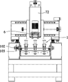
Embodiment, referring to Fig. 1 to Figure 11, what the present embodiment provided is a kind of from moving bistrique five-shaft numerical control polishing machine, it comprises a plurality of semiaxis bistriques 1, fuselage cradle 2, controller 3 and being connected with this controller 3 respectively, and be subject to the polisher head 4 of its control, bistrique feed mechanism 5, main shaft claming device 6, Z axis driving mechanism 7, X-axis driving mechanism 8, Y-axis driving mechanism 9, A axle rotary table 10 and C axle rotating mechanism, described X-axis driving mechanism 8 is arranged on described fuselage cradle 2 by Y-axis driving mechanism 9, described polisher head 4 is arranged on described X-axis driving mechanism 8 by described Z axis driving mechanism 7, described main shaft claming device 6 is arranged on the lower end of described polisher head 4, a plurality of semiaxis bistriques 1 also come on described bistrique feed mechanism 5, one side position of the corresponding described main shaft claming device 6 of this bistrique feed mechanism 5 is arranged on described fuselage cradle 2, and can carry semiaxis bistrique 1 to this main shaft claming device 6, described A axle rotary table 10 is horizontally set on described fuselage cradle 2, and can take the A axle as the axle center rotation, this A axle parallels with the axis of X-axis, described C axle rotating mechanism is arranged on described A axle rotary table 10, and can drive fixture 11 to take the C axle as the axle center rotation, this C axle parallels with the axis of Z axis.
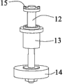
Described semiaxis bistrique 1 comprises main shaft 12, bearing block 13 and bistrique 14, and this bistrique 14 is arranged on the lower end of described main shaft 12, and described bearing block 13 is arranged on the medium position of described main shaft 12, and the upper end of described main shaft 12 is provided with and connects dop 15.
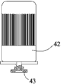
Described polisher head 4 comprises headstock 41 and spindle motor 42, described spindle motor 42 is arranged on described headstock 41, and make the rotating shaft of this spindle motor 42 towards described A axle rotary table 10, this rotating shaft is provided with and the described suitable main shaft joint 43 of dop 15 that is connected.
Described main shaft claming device 6 comprises two jaws 61, cylinder 62, spring 63 and the piece 64 that is connected and fixed, two jaw 61 symmetries are hinged on the two ends of the piece 64 that is connected and fixed, the lower end of two jaws 61 is provided with the bayonet socket suitable with described bearing block 13, described spring 63 is arranged on the top position of this piece 64 that is connected and fixed, and the two ends correspondence is pressed on two jaws 61, can make the lower end of two jaws 61 do to draw in action, described cylinder 62 is arranged on the top position of this spring 63, and the two ends correspondence is connected on two jaws 61, can make the lower end of two jaws 61 do separately action.
Described bistrique feed mechanism 5 comprises bistrique frame 51, supplies with guide rail 52 and supplies with motor, described bistrique frame 51 is movably arranged on described fuselage cradle 2 by supplying with guide rail 52, described supply motor is arranged on described fuselage cradle 2, and can drive bistrique frame 51 to do reciprocating action in supplying with on guide rail 52 by supplying with leading screw, described bistrique frame 51 is provided with the suitable screens 53 of a plurality of and described semiaxis bistrique 1, and the bottom of this screens 53 is provided with can be by described semiaxis bistrique 1 location binding clasp 54 thereon.
Described A axle rotary table 10 comprises A axle turntable 101, A rotating shaft 102 and A axis drive motor, the two ends of described A axle turntable 101 respectively are movably arranged on described fuselage cradle 2 by a described A rotating shaft 102, A rotating shaft 102 is provided with deceleration helical gear 103, described A axis drive motor is arranged on described fuselage cradle 2, and is connected with described deceleration helical gear 103 by the transmission synchronous belt; Fixture 11 is arranged on described A axle turntable 101 by described C axle rotating mechanism.
Described Y-axis driving mechanism 9 comprises Y-axis drive motors, Y-axis guide rail 91 and Y-axis slide 92, the both sides of described fuselage cradle 2 are provided with track base 93, described Y-axis guide rail 91 is arranged on this track base 93, described Y-axis slide 92 is slidably arranged on Y-axis guide rail 91, described Y-axis drive motors is arranged on described fuselage cradle 2, and can drive Y-axis slide 92 to do reciprocating action on Y-axis guide rail 91 by the Y-axis leading screw.
Described X-axis driving mechanism 8 comprises portal frame 81, X-axis drive motors, X-axis guide rail 82 and X-axis slide 83, described portal frame 81 is arranged on described Y-axis slide 92, described X-axis guide rail 82 is arranged on the front side wall of described portal frame 81, described X-axis slide 83 is slidably arranged on X-axis guide rail 82, described X-axis drive motors is arranged on described portal frame 81, and can drive X-axis slide 83 to do reciprocating action on X-axis guide rail 82 by X axis leading screw 84.
Described Z axis driving mechanism 7 comprises Z axis drive motors, Z axis guide rail 71 and Z axis slide 72, described Z axis guide rail 71 is arranged on described X-axis slide 83, described Z axis slide 72 is slidably arranged on Z axis guide rail 71, described Z axis drive motors is arranged on described X-axis slide, and can drive Z axis slide 72 to do reciprocating action on Z axis guide rail 71 by Z-axis direction leading screw 73.
The lateral wall of described fuselage cradle 2 is provided with protective plate 21, is provided with protective plate 21, safe, effectively eliminates safe hidden trouble.Described controller 3 is arranged on a sidewall of described fuselage cradle 2, and this controller 3 is provided with display screen, and described fuselage cradle 2 is provided with deduster, and this deduster is connected with described controller 3.Be provided with deduster, effectively improve working environment, avoid dust to raise outward, favourable operating personnel are healthy.
During work, by clamping workpiece on fixture 11, burnishing parameters input information controller 3 that will be relevant to workpiece, control the cooperating of described polisher head 4, bistrique feed mechanism 5, main shaft claming device 6, Z axis driving mechanism 7, X-axis driving mechanism 8, Y-axis driving mechanism 9, A axle rotary table 10 and C axle rotating mechanism by this controller 3, five-axle linkage simultaneously, flexibility is high, can carry out polishing to the surface of complex-curved shape, disposable clamping just can complete a plurality of polishing processes, as operations such as roughing, fine finishining, mirror finishes.Be the 2-3 operating efficiency doubly of staff polishing, not only improve working (machining) efficiency, also greatly reduce operator's labour intensity.
In the present embodiment, be provided with three semiaxis bistriques 1, first semiaxis bistrique is for roughing, and second semiaxis bistrique is for fine finishining, and the 3rd semiaxis bistrique is for mirror finish.In other embodiment, can carry out according to required polishing effect quantity and the type of relative set semiaxis bistrique.
While needing to change bistrique, bistrique feed mechanism 5 is carried the semiaxis bistrique to described main shaft claming device 6.By the common cooperation of Z axis driving mechanism 7, X-axis driving mechanism 8 and Y-axis driving mechanism 9, polisher head 4 is moved on the empty calorie position, and make the semiaxis bistrique on this main shaft claming device 6 snap in this screens, the binding clasp 54 in this screens clamps this semiaxis bistrique.Cylinder 62 stretches Compress Spring 63 makes two jaws 61 do separately action, and this jaw 61 and the semiaxis bistrique on it are separated.And then by the common cooperation of Z axis driving mechanism 7, X-axis driving mechanism 8 and Y-axis driving mechanism 9, polisher head 4 is moved on the semiaxis bistrique position of required replacing, Z axis driving mechanism 7 drives polisher head 4 to move downward, make main shaft joint 43 and be connected dop 15 and match, at this moment, cylinder 62 shrinks, and spring 63 utilizes self elastic force to make two jaws 61 do to draw in action, realizes changing the bistrique purpose.
The announcement of book and instruction according to the above description, those skilled in the art in the invention can also be changed and be revised above-mentioned embodiment.Therefore, the present invention is not limited to the specific embodiment disclosed and described above, to modifications and changes more of the present invention, also should fall in the protection domain of claim of the present invention.In addition, although used some specific terms in this specification, these terms just for convenience of description, do not form any restriction to the present invention, adopt other polishing machine same or analogous with it, all in protection domain of the present invention.
Claims (10)
1. certainly move bistrique five-shaft numerical control polishing machine for one kind, it is characterized in that, it comprises a plurality of semiaxis bistriques, fuselage cradle, controller and being connected with this controller respectively, and be subject to the polisher head of its control, the bistrique feed mechanism, the main shaft claming device, the Z axis driving mechanism, the X-axis driving mechanism, the Y-axis driving mechanism, A axle rotary table and C axle rotating mechanism, described X-axis driving mechanism is arranged on described fuselage cradle by the Y-axis driving mechanism, described polisher head is arranged on described X-axis driving mechanism by described Z axis driving mechanism, described main shaft claming device is arranged on the lower end of described polisher head, a plurality of semiaxis bistriques also come on described bistrique feed mechanism, one side position of the corresponding described main shaft claming device of this bistrique feed mechanism is arranged on described fuselage cradle, and can carry the semiaxis bistrique to this main shaft claming device, described A axle rotary table is horizontally set on described fuselage cradle, and can take the A axle as the axle center rotation, this A axle parallels with the axis of X-axis, described C axle rotating mechanism is arranged on described A axle rotary table, and can drive fixture to take the C axle as the axle center rotation, this C axle parallels with the axis of Z axis.
2. according to claim 1 from moving bistrique five-shaft numerical control polishing machine, it is characterized in that: described semiaxis bistrique comprises main shaft, bearing block and bistrique, this bistrique is arranged on the lower end of described main shaft, described bearing block is arranged on the medium position of described main shaft, and the upper end of described main shaft is provided with the connection dop.
3. according to claim 2 from moving bistrique five-shaft numerical control polishing machine, it is characterized in that: described polisher head comprises headstock and spindle motor, described spindle motor is arranged on described headstock, and make the rotating shaft of this spindle motor towards described A axle rotary table, this rotating shaft is provided with and the described suitable main shaft joint of dop that is connected.
4. according to claim 3 from moving bistrique five-shaft numerical control polishing machine, it is characterized in that: described main shaft claming device comprises two jaws, cylinder, spring and the piece that is connected and fixed, two jaw symmetries are hinged on the two ends of the piece that is connected and fixed, the lower end of two jaws is provided with the bayonet socket suitable with described bearing block, described spring is arranged on the top position of this piece that is connected and fixed, and the two ends correspondence is pressed on two jaws, can make the lower end of two jaws do to draw in action, described cylinder is arranged on the top position of this spring, and the two ends correspondence is connected on two jaws, can make the lower end of two jaws do separately action.
5. according to claim 1 from moving bistrique five-shaft numerical control polishing machine, it is characterized in that: described bistrique feed mechanism comprises the bistrique frame, supplies with guide rail and supplies with motor, described bistrique frame is movably arranged on described fuselage cradle by supplying with guide rail, described supply motor is arranged on described fuselage cradle, and can drive the bistrique frame to do reciprocating action in supplying with on guide rail by supplying with leading screw, described bistrique frame is provided with the suitable screens of a plurality of and described semiaxis bistrique, and the bottom of this screens is provided with can be by described semiaxis bistrique location binding clasp thereon.
6. according to claim 1 from moving bistrique five-shaft numerical control polishing machine, it is characterized in that: described A axle rotary table comprises A axle turntable, A rotating shaft and A axis drive motor, the two ends of described A axle turntable respectively are movably arranged on described fuselage cradle by a described A rotating shaft, the A rotating shaft is provided with the deceleration helical gear, described A axis drive motor is arranged on described fuselage cradle, and is connected with described deceleration helical gear by the transmission synchronous belt; Fixture is arranged on described A axle turntable by described C axle rotating mechanism.
7. according to claim 1 from moving bistrique five-shaft numerical control polishing machine, it is characterized in that: described Y-axis driving mechanism comprises Y-axis drive motors, Y-axis guide rail and Y-axis slide, the both sides of described fuselage cradle are provided with track base, described Y-axis guide rail is arranged on this track base, described Y-axis slide is slidably arranged on the Y-axis guide rail, described Y-axis drive motors is arranged on described fuselage cradle, and can drive the Y-axis slide to do reciprocating action on the Y-axis guide rail by the Y-axis leading screw.
8. according to claim 7 from moving bistrique five-shaft numerical control polishing machine, it is characterized in that: described X-axis driving mechanism comprises portal frame, X-axis drive motors, X-axis guide rail and X-axis slide, described portal frame is arranged on described Y-axis slide, described X-axis guide rail is arranged on the front side wall of described portal frame, described X-axis slide is slidably arranged on the X-axis guide rail, described X-axis drive motors is arranged on described portal frame, and can drive the X-axis slide to do reciprocating action on the X-axis guide rail by the X axis leading screw.
9. according to claim 8 from moving bistrique five-shaft numerical control polishing machine, it is characterized in that: described Z axis driving mechanism comprises Z axis drive motors, Z axis guide rail and Z axis slide, described Z axis guide rail is arranged on described X-axis slide, described Z axis slide is slidably arranged on the Z axis guide rail, described Z axis drive motors is arranged on described X-axis slide, and can drive the Z axis slide to do reciprocating action on the Z axis guide rail by the Z-axis direction leading screw.
10. according to claim 1 from moving bistrique five-shaft numerical control polishing machine, it is characterized in that: the lateral wall of described fuselage cradle is provided with protective plate, described controller is arranged on a sidewall of described fuselage cradle, this controller is provided with display screen, described fuselage cradle is provided with deduster, and this deduster is connected with described controller.
Priority Applications (1)
| Application Number | Priority Date | Filing Date | Title |
|---|---|---|---|
| CN201310391910.2A CN103465145B (en) | 2013-09-03 | 2013-09-03 | Five-axis numerical control polishing machine capable of changing grinding heads automatically |
Applications Claiming Priority (1)
| Application Number | Priority Date | Filing Date | Title |
|---|---|---|---|
| CN201310391910.2A CN103465145B (en) | 2013-09-03 | 2013-09-03 | Five-axis numerical control polishing machine capable of changing grinding heads automatically |
Publications (2)
| Publication Number | Publication Date |
|---|---|
| CN103465145A true CN103465145A (en) | 2013-12-25 |
| CN103465145B CN103465145B (en) | 2017-05-10 |
Family
ID=49790307
Family Applications (1)
| Application Number | Title | Priority Date | Filing Date |
|---|---|---|---|
| CN201310391910.2A Expired - Fee Related CN103465145B (en) | 2013-09-03 | 2013-09-03 | Five-axis numerical control polishing machine capable of changing grinding heads automatically |
Country Status (1)
| Country | Link |
|---|---|
| CN (1) | CN103465145B (en) |
Cited By (44)
| Publication number | Priority date | Publication date | Assignee | Title |
|---|---|---|---|---|
| CN103894913A (en) * | 2014-02-28 | 2014-07-02 | 苏州冠捷精密机械有限公司 | Polishing machine |
| CN104097072A (en) * | 2014-08-08 | 2014-10-15 | 苏州明志科技有限公司 | Quasi-five-axis machining centre and machining method thereof |
| CN104117889A (en) * | 2014-07-29 | 2014-10-29 | 纽威数控装备(苏州)有限公司 | Small high-precision spherical grinding machine device |
| CN104476359A (en) * | 2014-11-20 | 2015-04-01 | 广州遂联自动化设备有限公司 | Brazing part profile polishing and grinding device |
| CN104607948A (en) * | 2014-12-12 | 2015-05-13 | 武汉理工大学 | Milling-grinding and cleaning equipment for cast pieces and forged pieces |
| CN104690614A (en) * | 2015-02-03 | 2015-06-10 | 东莞市力华机械设备有限公司 | Double-station internal polishing machine |
| CN105033827A (en) * | 2015-07-09 | 2015-11-11 | 深圳蓝狐思谷科技有限公司 | Full-automatic grinding and polishing device |
| CN105269441A (en) * | 2015-11-03 | 2016-01-27 | 嘉善龙翔人造毛绒有限公司 | Polishing device |
| CN105290935A (en) * | 2015-11-19 | 2016-02-03 | 苏州博义诺智能装备有限公司 | Automatic polishing device for mobile phone rear shell |
| CN105666314A (en) * | 2016-03-28 | 2016-06-15 | 东莞职业技术学院 | Grinding equipment for ultra-thin glass |
| CN105665603A (en) * | 2016-02-24 | 2016-06-15 | 浙江大学 | Five-axis linkage numerical control drill-rivet equipment with dual-rotational motion shaft single-drive mechanism |
| CN105690253A (en) * | 2016-03-11 | 2016-06-22 | 无锡建凌电器有限公司 | Clamping device for hardware part polishing machine |
| CN106312736A (en) * | 2016-10-31 | 2017-01-11 | 东港启鑫科技有限公司 | Automatic end portion edge polishing machine for stainless steel tableware |
| CN106426173A (en) * | 2016-11-04 | 2017-02-22 | 华南理工大学 | Robot grinding system for solving deformation problem and track planning method of robot grinding system |
| CN106737013A (en) * | 2016-11-17 | 2017-05-31 | 天津利顺利科技发展有限公司 | A kind of preparation method of die surface burnishing device |
| CN106956202A (en) * | 2017-04-21 | 2017-07-18 | 海宁市锦新轴承有限公司 | A kind of polissoir |
| CN107186602A (en) * | 2017-05-05 | 2017-09-22 | 东莞市金铸机械设备有限公司 | A kind of five-shaft numerical control polishing machine |
| CN107297651A (en) * | 2017-08-10 | 2017-10-27 | 安徽英冉信息咨询有限公司 | A kind of counter body polishing grinding device |
| CN107537625A (en) * | 2016-06-27 | 2018-01-05 | 无锡市科洋自动化研究所 | A kind of grinding head assembly for grain grinding |
| CN107756153A (en) * | 2016-08-23 | 2018-03-06 | 烟台中集来福士海洋工程有限公司 | Cutter grinding apparatus |
| CN107932280A (en) * | 2017-11-26 | 2018-04-20 | 苏州维创度信息科技有限公司 | A kind of automobile gimbal polishing process |
| CN107932279A (en) * | 2017-11-26 | 2018-04-20 | 苏州维创度信息科技有限公司 | A kind of automobile gimbal sanding apparatus |
| CN108422292A (en) * | 2018-04-10 | 2018-08-21 | 哈尔滨理工大学 | Kirschner wire processing method with chip space and equipment |
| CN108723922A (en) * | 2018-07-03 | 2018-11-02 | 汕头市新源丰餐具有限公司 | A kind of tableware edging automatic machine |
| CN108857843A (en) * | 2018-08-23 | 2018-11-23 | 深圳市五力波智能装备有限公司 | A kind of automatic polishing machine |
| CN109129079A (en) * | 2018-09-17 | 2019-01-04 | 浙江洋铭工贸有限公司 | A kind of burr polishing device |
| CN109397088A (en) * | 2018-12-18 | 2019-03-01 | 东莞市金太阳精密技术有限责任公司 | A kind of polishing machine of quick-replaceable bistrique or grinding head fixture |
| CN109514390A (en) * | 2018-12-29 | 2019-03-26 | 山东大学 | A kind of grinding attachment and method for grinding for tooth grinding |
| CN109623584A (en) * | 2018-12-19 | 2019-04-16 | 东莞市春草研磨科技有限公司 | Five-shaft numerical control abrasive belt grinding machine |
| CN110509160A (en) * | 2019-09-02 | 2019-11-29 | 深圳市精速五金机械有限公司 | A kind of pipe fitting automation five-axle linkage polishing machine |
| CN110883666A (en) * | 2019-12-12 | 2020-03-17 | 胶州市欧盖金属制品有限公司 | Two-sided rust cleaning device of different thickness abandonment metal sheet |
| CN110900335A (en) * | 2019-12-06 | 2020-03-24 | 马鞍山元辰网络科技有限公司 | PCB double-sided board grinding device for electronic product and working method thereof |
| CN111002161A (en) * | 2019-11-30 | 2020-04-14 | 闫志伟 | Industrial robot burnishing and polishing equipment |
| CN111360663A (en) * | 2020-04-26 | 2020-07-03 | 马远强 | Convenient movable full-automatic grinding machine |
| CN111397719A (en) * | 2020-04-08 | 2020-07-10 | 常州市富月砝码有限公司 | Full-automatic high accuracy electronic scale precision check system |
| CN112192383A (en) * | 2020-11-30 | 2021-01-08 | 宁波米锐汽车配件技术有限公司 | A multi-angle grinding device for car fastener |
| CN112223033A (en) * | 2020-10-20 | 2021-01-15 | 芜湖县兴振模具有限公司 | Car rearview mirror mould grinding device |
| CN112643540A (en) * | 2020-12-08 | 2021-04-13 | 江西美硕实业有限公司 | Underwear processing positioning and clamping device for clothing production |
| CN112658944A (en) * | 2021-03-16 | 2021-04-16 | 湖南宇环精密制造有限公司 | Five-axis linkage polishing machine for gantry |
| CN112720113A (en) * | 2021-01-08 | 2021-04-30 | 周成建 | High-end equipment manufacturing steel plate surface polishing equipment |
| CN113172535A (en) * | 2021-04-28 | 2021-07-27 | 蓝思智能机器人(长沙)有限公司 | Polishing machine |
| CN114905358A (en) * | 2022-04-07 | 2022-08-16 | 九江金鹰科技有限公司 | Five-axis linkage automatic edge grinding machine |
| CN117583574A (en) * | 2024-01-09 | 2024-02-23 | 广州市型腔模具制造有限公司 | Deburring device for metal die castings of new energy automobiles |
| CN109623584B (en) * | 2018-12-19 | 2024-04-26 | 东莞市春草研磨科技有限公司 | Five-axis numerical control abrasive belt grinding machine |
Citations (7)
| Publication number | Priority date | Publication date | Assignee | Title |
|---|---|---|---|---|
| CN202015992U (en) * | 2011-04-22 | 2011-10-26 | 赵明杰 | Five-axis linkage numerical control polisher |
| CN102615578A (en) * | 2012-04-10 | 2012-08-01 | 张瑞杰 | Five-axis precision polishing machine |
| CN102765035A (en) * | 2012-07-31 | 2012-11-07 | 广州市敏嘉制造技术有限公司 | Four-spindle vertical numerical control grinding center |
| CN102773796A (en) * | 2012-08-16 | 2012-11-14 | 苏州珈玛自动化科技有限公司 | Grinding head structure of polishing machine |
| CN102794695A (en) * | 2012-08-16 | 2012-11-28 | 苏州珈玛自动化科技有限公司 | Five-shaft polishing machine |
| CN202779948U (en) * | 2012-07-11 | 2013-03-13 | 深圳市精一智能机械有限公司 | Five-axis numerical control engraving and milling machine |
| CN203566464U (en) * | 2013-09-03 | 2014-04-30 | 东莞市钜铧机械有限公司 | Five-axis numerical control polishing machine with grinding heads capable of being replaced automatically |
-
2013
- 2013-09-03 CN CN201310391910.2A patent/CN103465145B/en not_active Expired - Fee Related
Patent Citations (7)
| Publication number | Priority date | Publication date | Assignee | Title |
|---|---|---|---|---|
| CN202015992U (en) * | 2011-04-22 | 2011-10-26 | 赵明杰 | Five-axis linkage numerical control polisher |
| CN102615578A (en) * | 2012-04-10 | 2012-08-01 | 张瑞杰 | Five-axis precision polishing machine |
| CN202779948U (en) * | 2012-07-11 | 2013-03-13 | 深圳市精一智能机械有限公司 | Five-axis numerical control engraving and milling machine |
| CN102765035A (en) * | 2012-07-31 | 2012-11-07 | 广州市敏嘉制造技术有限公司 | Four-spindle vertical numerical control grinding center |
| CN102773796A (en) * | 2012-08-16 | 2012-11-14 | 苏州珈玛自动化科技有限公司 | Grinding head structure of polishing machine |
| CN102794695A (en) * | 2012-08-16 | 2012-11-28 | 苏州珈玛自动化科技有限公司 | Five-shaft polishing machine |
| CN203566464U (en) * | 2013-09-03 | 2014-04-30 | 东莞市钜铧机械有限公司 | Five-axis numerical control polishing machine with grinding heads capable of being replaced automatically |
Cited By (57)
| Publication number | Priority date | Publication date | Assignee | Title |
|---|---|---|---|---|
| CN103894913A (en) * | 2014-02-28 | 2014-07-02 | 苏州冠捷精密机械有限公司 | Polishing machine |
| CN104117889A (en) * | 2014-07-29 | 2014-10-29 | 纽威数控装备(苏州)有限公司 | Small high-precision spherical grinding machine device |
| CN104097072B (en) * | 2014-08-08 | 2016-08-24 | 苏州明志科技有限公司 | A kind of quasi-Five-axis NC Machining Center and processing method thereof |
| CN104097072A (en) * | 2014-08-08 | 2014-10-15 | 苏州明志科技有限公司 | Quasi-five-axis machining centre and machining method thereof |
| CN104476359A (en) * | 2014-11-20 | 2015-04-01 | 广州遂联自动化设备有限公司 | Brazing part profile polishing and grinding device |
| CN104607948A (en) * | 2014-12-12 | 2015-05-13 | 武汉理工大学 | Milling-grinding and cleaning equipment for cast pieces and forged pieces |
| CN104690614A (en) * | 2015-02-03 | 2015-06-10 | 东莞市力华机械设备有限公司 | Double-station internal polishing machine |
| CN104690614B (en) * | 2015-02-03 | 2023-09-08 | 广东力华感应设备有限公司 | Double-station inner polishing machine |
| CN105033827A (en) * | 2015-07-09 | 2015-11-11 | 深圳蓝狐思谷科技有限公司 | Full-automatic grinding and polishing device |
| CN105033827B (en) * | 2015-07-09 | 2018-04-10 | 深圳蓝狐思谷科技有限公司 | A kind of full-automatic sanding polissoir |
| CN105269441A (en) * | 2015-11-03 | 2016-01-27 | 嘉善龙翔人造毛绒有限公司 | Polishing device |
| CN105290935A (en) * | 2015-11-19 | 2016-02-03 | 苏州博义诺智能装备有限公司 | Automatic polishing device for mobile phone rear shell |
| CN105665603A (en) * | 2016-02-24 | 2016-06-15 | 浙江大学 | Five-axis linkage numerical control drill-rivet equipment with dual-rotational motion shaft single-drive mechanism |
| CN105665603B (en) * | 2016-02-24 | 2018-01-09 | 浙江大学 | 5-shaft linkage numerical control with dual AC power kinematic axis single driving mechanism bores riveting equipment |
| CN105690253A (en) * | 2016-03-11 | 2016-06-22 | 无锡建凌电器有限公司 | Clamping device for hardware part polishing machine |
| CN105666314A (en) * | 2016-03-28 | 2016-06-15 | 东莞职业技术学院 | Grinding equipment for ultra-thin glass |
| CN107537625A (en) * | 2016-06-27 | 2018-01-05 | 无锡市科洋自动化研究所 | A kind of grinding head assembly for grain grinding |
| CN107756153A (en) * | 2016-08-23 | 2018-03-06 | 烟台中集来福士海洋工程有限公司 | Cutter grinding apparatus |
| CN107756153B (en) * | 2016-08-23 | 2021-08-20 | 烟台中集来福士海洋工程有限公司 | Cutter grinding equipment |
| CN106312736B (en) * | 2016-10-31 | 2019-02-15 | 东港启鑫科技有限公司 | A kind of stainless steel tableware auto tip makes side machine |
| CN106312736A (en) * | 2016-10-31 | 2017-01-11 | 东港启鑫科技有限公司 | Automatic end portion edge polishing machine for stainless steel tableware |
| CN106426173B (en) * | 2016-11-04 | 2019-08-20 | 华南理工大学 | For the robot grinding system and its method for planning track for solving deformation problems |
| CN106426173A (en) * | 2016-11-04 | 2017-02-22 | 华南理工大学 | Robot grinding system for solving deformation problem and track planning method of robot grinding system |
| CN106737013A (en) * | 2016-11-17 | 2017-05-31 | 天津利顺利科技发展有限公司 | A kind of preparation method of die surface burnishing device |
| CN106956202A (en) * | 2017-04-21 | 2017-07-18 | 海宁市锦新轴承有限公司 | A kind of polissoir |
| CN107186602B (en) * | 2017-05-05 | 2018-11-23 | 东莞市金铸机械设备有限公司 | A kind of five-shaft numerical control polishing machine |
| CN107186602A (en) * | 2017-05-05 | 2017-09-22 | 东莞市金铸机械设备有限公司 | A kind of five-shaft numerical control polishing machine |
| CN107297651A (en) * | 2017-08-10 | 2017-10-27 | 安徽英冉信息咨询有限公司 | A kind of counter body polishing grinding device |
| CN107932279A (en) * | 2017-11-26 | 2018-04-20 | 苏州维创度信息科技有限公司 | A kind of automobile gimbal sanding apparatus |
| CN107932280A (en) * | 2017-11-26 | 2018-04-20 | 苏州维创度信息科技有限公司 | A kind of automobile gimbal polishing process |
| CN108422292A (en) * | 2018-04-10 | 2018-08-21 | 哈尔滨理工大学 | Kirschner wire processing method with chip space and equipment |
| CN108723922A (en) * | 2018-07-03 | 2018-11-02 | 汕头市新源丰餐具有限公司 | A kind of tableware edging automatic machine |
| CN108857843A (en) * | 2018-08-23 | 2018-11-23 | 深圳市五力波智能装备有限公司 | A kind of automatic polishing machine |
| CN108857843B (en) * | 2018-08-23 | 2024-04-30 | 深圳市五力波智能科技有限公司 | Automatic polishing machine |
| CN109129079A (en) * | 2018-09-17 | 2019-01-04 | 浙江洋铭工贸有限公司 | A kind of burr polishing device |
| CN109397088B (en) * | 2018-12-18 | 2024-01-09 | 东莞市金太阳精密技术有限责任公司 | Polishing machine capable of quickly replacing grinding head or grinding head clamp |
| CN109397088A (en) * | 2018-12-18 | 2019-03-01 | 东莞市金太阳精密技术有限责任公司 | A kind of polishing machine of quick-replaceable bistrique or grinding head fixture |
| CN109623584A (en) * | 2018-12-19 | 2019-04-16 | 东莞市春草研磨科技有限公司 | Five-shaft numerical control abrasive belt grinding machine |
| CN109623584B (en) * | 2018-12-19 | 2024-04-26 | 东莞市春草研磨科技有限公司 | Five-axis numerical control abrasive belt grinding machine |
| CN109514390A (en) * | 2018-12-29 | 2019-03-26 | 山东大学 | A kind of grinding attachment and method for grinding for tooth grinding |
| CN110509160A (en) * | 2019-09-02 | 2019-11-29 | 深圳市精速五金机械有限公司 | A kind of pipe fitting automation five-axle linkage polishing machine |
| CN111002161A (en) * | 2019-11-30 | 2020-04-14 | 闫志伟 | Industrial robot burnishing and polishing equipment |
| CN110900335A (en) * | 2019-12-06 | 2020-03-24 | 马鞍山元辰网络科技有限公司 | PCB double-sided board grinding device for electronic product and working method thereof |
| CN110883666A (en) * | 2019-12-12 | 2020-03-17 | 胶州市欧盖金属制品有限公司 | Two-sided rust cleaning device of different thickness abandonment metal sheet |
| CN111397719A (en) * | 2020-04-08 | 2020-07-10 | 常州市富月砝码有限公司 | Full-automatic high accuracy electronic scale precision check system |
| CN111360663A (en) * | 2020-04-26 | 2020-07-03 | 马远强 | Convenient movable full-automatic grinding machine |
| CN111360663B (en) * | 2020-04-26 | 2021-08-31 | 佛山市运旺科技实业有限公司 | Convenient movable full-automatic grinding machine |
| CN112223033A (en) * | 2020-10-20 | 2021-01-15 | 芜湖县兴振模具有限公司 | Car rearview mirror mould grinding device |
| CN112223033B (en) * | 2020-10-20 | 2022-07-15 | 芜湖县兴振模具有限公司 | Car rearview mirror mould grinding device |
| CN112192383B (en) * | 2020-11-30 | 2021-02-19 | 宁波米锐汽车配件技术有限公司 | A multi-angle grinding device for car fastener |
| CN112192383A (en) * | 2020-11-30 | 2021-01-08 | 宁波米锐汽车配件技术有限公司 | A multi-angle grinding device for car fastener |
| CN112643540A (en) * | 2020-12-08 | 2021-04-13 | 江西美硕实业有限公司 | Underwear processing positioning and clamping device for clothing production |
| CN112720113A (en) * | 2021-01-08 | 2021-04-30 | 周成建 | High-end equipment manufacturing steel plate surface polishing equipment |
| CN112658944A (en) * | 2021-03-16 | 2021-04-16 | 湖南宇环精密制造有限公司 | Five-axis linkage polishing machine for gantry |
| CN113172535A (en) * | 2021-04-28 | 2021-07-27 | 蓝思智能机器人(长沙)有限公司 | Polishing machine |
| CN114905358A (en) * | 2022-04-07 | 2022-08-16 | 九江金鹰科技有限公司 | Five-axis linkage automatic edge grinding machine |
| CN117583574A (en) * | 2024-01-09 | 2024-02-23 | 广州市型腔模具制造有限公司 | Deburring device for metal die castings of new energy automobiles |
Also Published As
| Publication number | Publication date |
|---|---|
| CN103465145B (en) | 2017-05-10 |
Similar Documents
| Publication | Publication Date | Title |
|---|---|---|
| CN203566464U (en) | Five-axis numerical control polishing machine with grinding heads capable of being replaced automatically | |
| CN103465145A (en) | Five-axis numerical control polishing machine capable of changing grinding heads automatically | |
| CN105415122B (en) | A kind of automation polishing production line of engine cylinder-body | |
| CN103506908A (en) | Method and device for automatically polishing wheel hub | |
| CN201998021U (en) | Numerical control grinder | |
| CN105290794A (en) | Multi-axis linkage numerical control trimming and burr cleaning-up tool | |
| CN210909279U (en) | Numerical control rotating table surface grinding machine | |
| CN106736630B (en) | Pentahedron processing machine | |
| CN106181687A (en) | A kind of blisk system of processing and method | |
| CN204658139U (en) | The floating polishing system of a kind of correction | |
| CN204843847U (en) | Work piece clamping positioning mechanism of numerical control cylindrical grinder | |
| CN201881214U (en) | Automatic saw web grinding machine | |
| CN207696279U (en) | A kind of grinding machine for processing end face and endoporus | |
| CN205342703U (en) | Engine cylinder block's automation production line of polishing | |
| CN209831271U (en) | Polishing device and polishing machine | |
| CN110842714A (en) | Multifunctional grinding machine | |
| CN214489913U (en) | Threading die relief grinding machine | |
| CN202507060U (en) | Automatic milling and drilling numerical control machine tool | |
| CN210024433U (en) | Automatic numerical control lathe polishes | |
| CN212019527U (en) | Vertical machine tool | |
| CN211103201U (en) | Four-axis cambered surface joint line polisher | |
| CN211728700U (en) | Multifunctional grinding machine | |
| CN210996699U (en) | Six machining centers | |
| CN210756342U (en) | Rotary disc type engraving and milling machine | |
| CN209811985U (en) | Porous polishing polisher |
Legal Events
| Date | Code | Title | Description |
|---|---|---|---|
| C06 | Publication | ||
| PB01 | Publication | ||
| C10 | Entry into substantive examination | ||
| SE01 | Entry into force of request for substantive examination | ||
| GR01 | Patent grant | ||
| GR01 | Patent grant | ||
| CF01 | Termination of patent right due to non-payment of annual fee |
Granted publication date: 20170510 Termination date: 20170903 |
|
| CF01 | Termination of patent right due to non-payment of annual fee |