CN102541088B - Solar tracking oriented one-dimensional driving two-dimensional output robot mechanism - Google Patents
Solar tracking oriented one-dimensional driving two-dimensional output robot mechanism Download PDFInfo
- Publication number
- CN102541088B CN102541088B CN201210007227XA CN201210007227A CN102541088B CN 102541088 B CN102541088 B CN 102541088B CN 201210007227X A CN201210007227X A CN 201210007227XA CN 201210007227 A CN201210007227 A CN 201210007227A CN 102541088 B CN102541088 B CN 102541088B
- Authority
- CN
- China
- Prior art keywords
- motor
- solar
- cam
- robot mechanism
- bidimensional
- Prior art date
- Legal status (The legal status is an assumption and is not a legal conclusion. Google has not performed a legal analysis and makes no representation as to the accuracy of the status listed.)
- Expired - Fee Related
Links
Images


Classifications
-
- F—MECHANICAL ENGINEERING; LIGHTING; HEATING; WEAPONS; BLASTING
- F24—HEATING; RANGES; VENTILATING
- F24S—SOLAR HEAT COLLECTORS; SOLAR HEAT SYSTEMS
- F24S30/00—Arrangements for moving or orienting solar heat collector modules
- F24S30/40—Arrangements for moving or orienting solar heat collector modules for rotary movement
-
- F—MECHANICAL ENGINEERING; LIGHTING; HEATING; WEAPONS; BLASTING
- F24—HEATING; RANGES; VENTILATING
- F24S—SOLAR HEAT COLLECTORS; SOLAR HEAT SYSTEMS
- F24S30/00—Arrangements for moving or orienting solar heat collector modules
- F24S2030/10—Special components
- F24S2030/13—Transmissions
- F24S2030/137—Transmissions for deriving one movement from another one, e.g. for deriving elevation movement from azimuth movement
-
- Y—GENERAL TAGGING OF NEW TECHNOLOGICAL DEVELOPMENTS; GENERAL TAGGING OF CROSS-SECTIONAL TECHNOLOGIES SPANNING OVER SEVERAL SECTIONS OF THE IPC; TECHNICAL SUBJECTS COVERED BY FORMER USPC CROSS-REFERENCE ART COLLECTIONS [XRACs] AND DIGESTS
- Y02—TECHNOLOGIES OR APPLICATIONS FOR MITIGATION OR ADAPTATION AGAINST CLIMATE CHANGE
- Y02E—REDUCTION OF GREENHOUSE GAS [GHG] EMISSIONS, RELATED TO ENERGY GENERATION, TRANSMISSION OR DISTRIBUTION
- Y02E10/00—Energy generation through renewable energy sources
- Y02E10/40—Solar thermal energy, e.g. solar towers
- Y02E10/47—Mountings or tracking
Abstract
The invention relates to a solar tracking oriented one-dimensional driving two-dimensional output robot mechanism. The invention provides the solar tracking oriented one-dimensional driving two-dimensional output robot mechanism which comprises a bracket, a solar component mounting plate, a cam, a motor, a first rotating shaft and a one-way coupler, wherein the motor is arranged on the bracket; the motor is connected with the cam through the one-way coupler; the motor is connected with the first rotating shaft; one end of the solar component mounting plate is hinged with the first rotating shaft; the other end of the solar component mounting plate is in contact with and butt-jointed with the cam; and the motor is connected with the solar component mounting plate through the first rotating shaft and is used for driving the solar component mounting plate to rotate around the edge of the cam. The solar tracking oriented one-dimensional driving two-dimensional output robot mechanism has the beneficial effects that: one motor input is converted into two rotating shaft outputs, the solar motion is tracked and a sunlight receiving surface of a solar component is vertical to the sunlight under a working state, so that the total volume of absorbed energy is increased, the cost is lower and the reliability is higher.
Description
Technical field
The present invention relates to adopt tracking cell to utilize sun power, relate in particular to and adopt tracking cell to utilize a kind of one dimensional driving bidimensional output device robot mechanism towards solar tracking in sun power.
Background technology
Solar automatic tracking system can increase the sun power that photovoltaic module receives, and improves daily power and year output power, but higher than fixed system cost, and more complicated.There are the problems such as the product systems reliability can not meet the demands, tracking error large, high cost in solar tracking system, how to design a kind of sexual valence high solar tracking system of gain that when generates electricity, both improved generated energy, and reduced again cost of investment and become problem demanding prompt solution.Existing solar tracking system mainly contains one-axis system, Twin-shaft machinery tracing-positioning system, and is specific as follows:
(1) uniaxiality tracking
Uniaxiality tracking generally adopts: the thing that 1. is in tilted layout is followed the tracks of; 2. focal line north and south is horizontally disposed, and thing is followed the tracks of; 3. the focal line thing is horizontally disposed, and follow the tracks of in north and south.The north-south that these three kinds of modes are all single axle rotation or east two are to tracking, and principle of work is substantially similar.The the principle of 1. planting tracking mode is that the rotating shaft north and south of tracking means is arranged, and the geographic latitude angle of the locality that tilts, east-west direction is followed the tracks of the sun, the Spring Equinox, the Autumnal Equinox two days among 1 year, sunray is vertical with cell panel, and all the other time sunray incident angles-23.5 ° and+23.5 ° between; The the principle of 2. planting tracking mode is that the rotating shaft North and South direction of tracker is arranged, according to the variation of the solar hour angle of calculated in advance, solar panel is done around the shaft uniform rotation and followed the tracks of the sun.Adopt this tracking mode, among 1 year, sunray is all oblique fire, and only the cell panel angle of incidence of sunlight is minimum constantly at high noon every day, and this moment, photovoltaic cell output was maximum; The 3. to plant tracking mode be that the rotating shaft thing is horizontally disposed, automatically adjusts cell panel according to the variation of the declination angle of calculated in advance and make around the shaft pitch rotation and follow the tracks of the sun, and the sun is followed the tracks of in the position of perhaps manually adjusting rotating shaft according to variation throughout the year.Theoretical analysis, among 3 kinds of uniaxiality trackings, 1. plant the mode optimum, and 3. to plant mode the poorest.Although single shaft tracking structure is simple, because incident ray can not be parallel with rich optical axis all the time, the effect of collecting sun power is unsatisfactory.
(2) double-axis tracking
Just can obtain maximum sun power if can both follow the tracks of the sun in the variation at altitude of the sun and declination angle, comprehensive trace is that double-axis tracking designs according to such requirement.Double-axis tracking can be divided into dual mode again: polar mounts comprehensive trace and elevation angle orientation angie type comprehensive trace.
The polar mounts comprehensive trace.One axle of its tracking means points to celestial sphere arctic, namely parallels with earth's axis, therefore be called pole axis; Another axle is vertical with pole axis, is called declination axis.During work, cell panel turns round around pole axis, and the setting of its rotating speed is opposite with rotational-angular velocity of the earth size equidirectional to be changed in order to the hour angle of following the tracks of the sun; Cell panel is in order to follow the tracks of the variation at declination angle around declination axis as pitch rotation.This tracking mode is also uncomplicated, but structurally the weight of cell panel is not by the pole axis axis, and the design comparison of pole axis fulcrum arrangement is difficult.
Elevation angle-orientation angie type solar tracking.Elevation angle and orientation angie type sun tracing method are called again horizontal system of coordinates double-axis tracking, and the azimuth axis of cell panel is perpendicular to ground level, and another root axle is vertical with azimuth axis, is called pitch axis.During work, cell panel rotates around azimuth axis according to the change in location of the sun and changes the position angle, does around pitch axis the pitch angle that luffing changes cell panel, thereby makes the normal of cell panel parallel with sunray all the time.The characteristics of this tracker are that tracking accuracy is high, and the weight of heat collector remains in the plane at Z-axis place, and the design comparison of supporting structure is easy.
Existing two axle solar tracking mechanisms have two classes basically, and a class is position angle/pitching angie type, and another kind of is polar mounts.Because the solar tracking mechanism load-bearing of polar mounts is uneven, be unsuitable for using in large-scale tracker.The follower principle of position angle pitching angie type is simple, needs the driving of diaxon, and manufacturing cost is high.There is document to propose spherical mechanism in parallel with three axles as follower, this mechanism structure complexity, and need Three-axis drive, manufacturing cost is higher.
Summary of the invention
In order to solve the problems of the prior art, the invention provides a kind of one dimensional driving bidimensional output device robot mechanism towards solar tracking.
the invention provides a kind of one dimensional driving bidimensional output device robot mechanism towards solar tracking, comprise support, the solar components installing plate, cam, motor, the first turning axle and unidirectional coupling, wherein, described motor is arranged on described support, described motor is connected with described cam by described unidirectional coupling, described motor is connected with described the first turning axle, one end of described solar components installing plate and described the first turning axle are hinged, the other end butt that contacts with described cam, described motor is connected with described solar components installing plate and drives described solar components installing plate around the rotation of the edge of described cam by described the first turning axle.
As a further improvement on the present invention, described solar components installing plate parallels with described cam with the hinging rotary axle of the hinged formation of described the first turning axle.
As a further improvement on the present invention, described motor is connected with the first gear, and described the first turning axle is connected with the second gear, and described the first gear is meshed with described the second gear.
As a further improvement on the present invention, described motor is connected with described the first gear by motor output shaft.
As a further improvement on the present invention, described the second gear is connected with described unidirectional coupling.
As a further improvement on the present invention, described the second gear is connected with described unidirectional coupling by transmission shaft.
As a further improvement on the present invention, be connected with speed reduction unit between described unidirectional coupling and described cam.
As a further improvement on the present invention, described speed reduction unit is connected with described cam by reducer output shaft.
As a further improvement on the present invention, described the first turning axle and described support are hinged.
As a further improvement on the present invention, described support comprises base plate, the pillar that is connected with described base plate and the crossbeam that is connected with described pillar, and the two ends of described the first turning axle are hinged with the two ends of described crossbeam respectively.
the invention has the beneficial effects as follows: pass through such scheme, on the one hand, can be by motor-driven solar components installing plate around the rotation of the edge of cam, when the motor forward, the solar components installing plate can be followed the sun and be forwarded the west to from east, when motor reversal, the solar components installing plate can reset again, be ready to follow the tracks of the sun of second day, to reach the purpose of solar tracking, on the other hand, can export unidirectional drive to cam by unidirectional coupling again, when the motor forward, not rotation of cam, when motor reversal, the cam rotation, realized changing to adjust along with the time contact point of cam and solar components installing plate, thereby the solar components installing plate is adjusted to the elevation angle that second day needs, change into two rotating shafts by a motor input and export and follow the tracks of solar motion, the sunlight receiving plane that makes solar components is vertical with sunshine in working order the time, improved the energy total amount that absorbs, in addition, use a motor owing to lacking than traditional sun tracker, cost is lower, reliability is higher.
Description of drawings
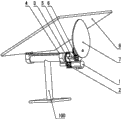
Fig. 1 is the perspective view of a kind of one dimensional driving bidimensional output device robot mechanism towards solar tracking of the present invention;
Fig. 2 is the perspective view at another visual angle of the one dimensional driving bidimensional output device robot mechanism towards solar tracking of the present invention;
Fig. 3 is the front view of the one dimensional driving bidimensional output device robot mechanism towards solar tracking of the present invention;
Fig. 4 is the left view of the one dimensional driving bidimensional output device robot mechanism towards solar tracking of the present invention;
Fig. 5 is the partial enlarged drawing A of Fig. 4.
Embodiment
The present invention is further described below in conjunction with description of drawings and embodiment.
Drawing reference numeral in Fig. 1 to Fig. 5 is: motor 1; Motor output shaft 11; The first gear 2; The second gear 3; Transmission shaft 31; The first turning axle 4; Unidirectional coupling 5; Speed reduction unit 6; Reducer output shaft 61; Cam 7; Solar components installing plate 8; Support 100; Base plate 101; Pillar 102; Crossbeam 103.
as extremely shown in Figure 5 in Fig. 1, a kind of one dimensional driving bidimensional output device robot mechanism towards solar tracking, comprise support 100, solar components installing plate 8, cam 7, motor 1, the first turning axle 4 and unidirectional coupling 5, wherein, described motor 1 is arranged on described support 100, described motor 1 is connected with described cam 7 by described unidirectional coupling 5, described motor 1 is connected with described the first turning axle 4, one end of described solar components installing plate 8 and described the first turning axle 4 are hinged, the other end butt that contacts with described cam 7, described motor 1 is connected with described solar components installing plate 8 and drives described solar components installing plate 8 around the rotation of the edge of described cam 7 by described the first turning axle 4, on described solar components installing plate 8, described solar components is installed, be used for sun transformation of energy.
To shown in Figure 5, described solar components installing plate 8 parallels with described cam 7 with the hinging rotary axle of the hinged formation of described the first turning axle 4 as Fig. 1.
As extremely shown in Figure 5 in Fig. 1, described motor 1 is connected with the first gear 2, described the first turning axle 4 is connected with the second gear 3, and described the first gear 2 is meshed with described the second gear 3, can realize by described the first gear 2 and described the second gear 3 the rotation output of motor.
To shown in Figure 5, described motor 1 is connected with described the first gear 2 by motor output shaft 11 as Fig. 1.
To shown in Figure 5, described the second gear 3 is connected with described unidirectional coupling 5 as Fig. 1.
To shown in Figure 5, described the second gear 3 is connected with described unidirectional coupling 5 by transmission shaft 31 as Fig. 1.
To shown in Figure 5, be connected with speed reduction unit 6 between described unidirectional coupling 5 and described cam 7 as Fig. 1.
To shown in Figure 5, described speed reduction unit 6 is connected with described cam 7 by reducer output shaft 61 as Fig. 1.
To shown in Figure 5, described the first turning axle 4 is hinged with described support 100 as Fig. 1.
To shown in Figure 5, described support 100 comprises base plate 101, the pillar 102 that is connected with described base plate 101 and the crossbeam 103 that is connected with described pillar 102 as Fig. 1, and the two ends of described the first turning axle 4 are hinged with the two ends of described crossbeam 103 respectively.
a kind of one dimensional driving bidimensional output device robot mechanism towards solar tracking provided by the invention, on the one hand, can be by motor 1, the first gear 2 and the second gear 3 drive solar components installing plate 8 around the rotation of the edge of cam 7 by the first turning axle 4, when motor 1 forward, solar components installing plate 8 can be followed the sun and be forwarded the west to from east, when motor 1 counter-rotating, solar components installing plate 8 can carry out again by west resetting to east, be ready to follow the tracks of the sun of second day, to reach the purpose of solar tracking, on the other hand, again can be by motor 1, the first gear 2 and the second gear 3 are by unidirectional coupling 5 and through the speed reduction unit 6 backward cam 7 output unidirectional drive of deceleration, wherein, the effect of speed reduction unit 6 is when motor 1 counter-rotating, can realize solar components installing plate 8 is resetted, can realize again cam 7 is carried out low-angle rotation adjustment, when motor 1 forward, cam 7 not rotations, with the contact point of maintenance cam on the same day 7 with solar components installing plate 8, namely keep solar components installing plate 8 elevation angle on the same day, when motor 1 counter-rotating, cam 7 rotations, and solar components installing plate 8 due to the gravity reason will follow cam 7 certainly then produce corresponding adjustment, because an end and described first turning axle 4 of described solar components installing plate 8 are hinged, the other end butt that contacts with described cam 7, therefore, cam 7 rotation adjustment be the angle of inclination of solar components installing plate 8, it is the elevation angle of solar components installing plate 8, realized changing to adjust along with the time contact point of cam 7 and solar components installing plate 8, thereby solar components installing plate 8 is adjusted to the elevation angle that second day needs, change into two rotating shafts by 1 input of a motor and export and follow the tracks of solar motion, the sunlight receiving plane that makes solar components is vertical with sunshine in working order the time, improved the energy total amount that absorbs, in addition, use a motor owing to lacking than traditional sun tracker, cost is lower, reliability is higher.
Above content is in conjunction with concrete preferred implementation further description made for the present invention, can not assert that concrete enforcement of the present invention is confined to these explanations.For the general technical staff of the technical field of the invention, without departing from the inventive concept of the premise, can also make some simple deduction or replace, all should be considered as belonging to protection scope of the present invention.
Claims (10)
1. one dimensional driving bidimensional output device robot mechanism towards solar tracking, it is characterized in that: comprise support, the solar components installing plate, cam, motor, the first turning axle and unidirectional coupling, wherein, described motor is arranged on described support, described motor is connected with described cam by described unidirectional coupling, described motor is connected with described the first turning axle, one end of described solar components installing plate and described the first turning axle are hinged, the other end butt that contacts with described cam, described motor is connected with described solar components installing plate and drives described solar components installing plate around the rotation of the edge of described cam by described the first turning axle.
2. according to claim 1 towards the one dimensional driving bidimensional output device robot mechanism of solar tracking, it is characterized in that: described solar components installing plate parallels with described cam with the hinging rotary axle of the hinged formation of described the first turning axle.
3. according to claim 1 towards the one dimensional driving bidimensional output device robot mechanism of solar tracking, it is characterized in that: described motor is connected with the first gear, and described the first turning axle is connected with the second gear, and described the first gear is meshed with described the second gear.
4. according to claim 3 towards the one dimensional driving bidimensional output device robot mechanism of solar tracking, it is characterized in that: described motor is connected with described the first gear by motor output shaft.
5. according to claim 3 towards the one dimensional driving bidimensional output device robot mechanism of solar tracking, it is characterized in that: described the second gear is connected with described unidirectional coupling.
6. according to claim 4 towards the one dimensional driving bidimensional output device robot mechanism of solar tracking, it is characterized in that: described the second gear is connected with described unidirectional coupling by transmission shaft.
7. according to claim 4 towards the one dimensional driving bidimensional output device robot mechanism of solar tracking, it is characterized in that: be connected with speed reduction unit between described unidirectional coupling and described cam.
8. according to claim 7 towards the one dimensional driving bidimensional output device robot mechanism of solar tracking, it is characterized in that: described speed reduction unit is connected with described cam by reducer output shaft.
9. according to claim 1 towards the one dimensional driving bidimensional output device robot mechanism of solar tracking, it is characterized in that: described the first turning axle and described support are hinged.
10. according to claim 1 towards the one dimensional driving bidimensional output device robot mechanism of solar tracking, it is characterized in that: described support comprises base plate, the pillar that is connected with described base plate and the crossbeam that is connected with described pillar, and the two ends of described the first turning axle are hinged with the two ends of described crossbeam respectively.
Priority Applications (1)
| Application Number | Priority Date | Filing Date | Title |
|---|---|---|---|
| CN201210007227XA CN102541088B (en) | 2012-01-11 | 2012-01-11 | Solar tracking oriented one-dimensional driving two-dimensional output robot mechanism |
Applications Claiming Priority (1)
| Application Number | Priority Date | Filing Date | Title |
|---|---|---|---|
| CN201210007227XA CN102541088B (en) | 2012-01-11 | 2012-01-11 | Solar tracking oriented one-dimensional driving two-dimensional output robot mechanism |
Publications (2)
| Publication Number | Publication Date |
|---|---|
| CN102541088A CN102541088A (en) | 2012-07-04 |
| CN102541088B true CN102541088B (en) | 2013-06-05 |
Family
ID=46348176
Family Applications (1)
| Application Number | Title | Priority Date | Filing Date |
|---|---|---|---|
| CN201210007227XA Expired - Fee Related CN102541088B (en) | 2012-01-11 | 2012-01-11 | Solar tracking oriented one-dimensional driving two-dimensional output robot mechanism |
Country Status (1)
| Country | Link |
|---|---|
| CN (1) | CN102541088B (en) |
Cited By (1)
| Publication number | Priority date | Publication date | Assignee | Title |
|---|---|---|---|---|
| IT201900015156A1 (en) * | 2019-08-28 | 2021-02-28 | Fausto Guglielmo | Double degree of freedom solar tracker generated simultaneously by a single actuator |
Families Citing this family (3)
| Publication number | Priority date | Publication date | Assignee | Title |
|---|---|---|---|---|
| CN103281012A (en) * | 2013-06-16 | 2013-09-04 | 姬志刚 | Wind and solar power generating mechanism capable of tracking sunlight |
| CN104426467B (en) * | 2013-09-03 | 2016-07-27 | 沈阳农业大学 | Residents photovoltaic cell is with electro-optical device |
| CN107616915A (en) * | 2017-08-02 | 2018-01-23 | 刘王 | A kind of decocting device |
Citations (3)
| Publication number | Priority date | Publication date | Assignee | Title |
|---|---|---|---|---|
| US4546756A (en) * | 1981-12-14 | 1985-10-15 | G&G Solar, Inc. | Tracking system |
| CN2533435Y (en) * | 2002-02-08 | 2003-01-29 | 顾学华 | Synchronous sun tracking device |
| US7898212B2 (en) * | 2001-04-06 | 2011-03-01 | Benn William M | Portable solar generator |
-
2012
- 2012-01-11 CN CN201210007227XA patent/CN102541088B/en not_active Expired - Fee Related
Patent Citations (3)
| Publication number | Priority date | Publication date | Assignee | Title |
|---|---|---|---|---|
| US4546756A (en) * | 1981-12-14 | 1985-10-15 | G&G Solar, Inc. | Tracking system |
| US7898212B2 (en) * | 2001-04-06 | 2011-03-01 | Benn William M | Portable solar generator |
| CN2533435Y (en) * | 2002-02-08 | 2003-01-29 | 顾学华 | Synchronous sun tracking device |
Cited By (1)
| Publication number | Priority date | Publication date | Assignee | Title |
|---|---|---|---|---|
| IT201900015156A1 (en) * | 2019-08-28 | 2021-02-28 | Fausto Guglielmo | Double degree of freedom solar tracker generated simultaneously by a single actuator |
Also Published As
| Publication number | Publication date |
|---|---|
| CN102541088A (en) | 2012-07-04 |
Similar Documents
| Publication | Publication Date | Title |
|---|---|---|
| CN201828831U (en) | Solar module array and polar shaft tracking device of solar collector | |
| CN101521478B (en) | Solar automatic tracking system | |
| CN103149947B (en) | Solar energy tracking method with umbra versa tracking | |
| CN204633687U (en) | Single flake type tracking support with double shafts device | |
| KR20090029587A (en) | Solar power plant having solar tracking apparatus | |
| KR100715040B1 (en) | Solar power plant having solar tracking apparatus | |
| CN201203037Y (en) | Solar light source automatic tracing apparatus | |
| CN102541088B (en) | Solar tracking oriented one-dimensional driving two-dimensional output robot mechanism | |
| CN102566587A (en) | Photovoltaic group tracking device | |
| CN201717805U (en) | Solar three-dimensional automatic track follower | |
| CN107491096B (en) | Efficient tracking type photovoltaic power generation system and matrix | |
| CN104777849A (en) | Horizontal-shaft scale-type dual-shaft dual-linkage tracking bracket device | |
| CN204761380U (en) | Array biax linkage sun tracking means | |
| CN204631631U (en) | A kind of flat axle flake type twin shaft Double-linkage follows the tracks of holder device | |
| CN203788228U (en) | Spindle connection structure of solar uniaxial tracker | |
| JP6342632B2 (en) | Solar concentrator | |
| CN206193546U (en) | Solar tracking system | |
| CN201956932U (en) | Photovoltaic group tracking device | |
| CN101295944A (en) | Solar two-dimension tracing apparatus | |
| CN101562411A (en) | Solar energy generating device | |
| CN201081444Y (en) | Gyro type gimbal frame for solar heat collector and solar cell panel | |
| CN201622470U (en) | Energy-saving environment-friendly sunlight tracking device | |
| CN201789437U (en) | Solar condensing device with fixed focus | |
| CN104460691A (en) | Wheel spring five-function sun tracking machine | |
| KR200423036Y1 (en) | solar power plant having solar tracking apparatus |
Legal Events
| Date | Code | Title | Description |
|---|---|---|---|
| C06 | Publication | ||
| PB01 | Publication | ||
| C10 | Entry into substantive examination | ||
| SE01 | Entry into force of request for substantive examination | ||
| C14 | Grant of patent or utility model | ||
| GR01 | Patent grant | ||
| C17 | Cessation of patent right | ||
| CF01 | Termination of patent right due to non-payment of annual fee |
Granted publication date: 20130605 Termination date: 20140111 |