CN102352632B - Anchor rod sheet pile combined structure and method for reinforcing high filling body on one side of slope - Google Patents
Anchor rod sheet pile combined structure and method for reinforcing high filling body on one side of slope Download PDFInfo
- Publication number
- CN102352632B CN102352632B CN 201110215014 CN201110215014A CN102352632B CN 102352632 B CN102352632 B CN 102352632B CN 201110215014 CN201110215014 CN 201110215014 CN 201110215014 A CN201110215014 A CN 201110215014A CN 102352632 B CN102352632 B CN 102352632B
- Authority
- CN
- China
- Prior art keywords
- anchor pole
- filling body
- baffle plate
- anchor
- concrete baffle
- Prior art date
- Legal status (The legal status is an assumption and is not a legal conclusion. Google has not performed a legal analysis and makes no representation as to the accuracy of the status listed.)
- Expired - Fee Related
Links
Images




Abstract
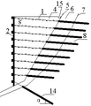
The invention discloses an anchor rod sheet pile combined structure and a method for reinforcing a high filling body on one side of a slope. The anchor rod sheet pile combined structure comprises an anchor rod (1), a concrete baffle (2) and a foundation pile (3), wherein the anchor rod (1) passes through a slope surface layer covering layer (6) to be connected with a stable bed rock (8) in a pouring slurry mode; an anchor head (9) of the anchor rod (1) is connected with the concrete baffle (2); the foundation pile (3) penetrates the stable bed rock (8) and is connected with the bottom of the concrete baffle (2); the part, in a filling body (4), of a rod body (11) of the anchor rod (1) is welded with short rods (10); the short rods (10) are arranged vertically and horizontally at intervals; the short rods (10) in the horizontal direction are welded and arranged on the upper part and the lower part of the rod body (11) at intervals; and the short rods (10) in the vertical direction are arranged on two sides of the rod body (11) at intervals. By the invention, the friction connecting capacity of the filling body and the anchor rod is greatly improved; the concrete baffle and the foundation pile are combined to form a stable and reliable system for retaining and reinforcing the high filling body on one side of the slope; the central height of the stable retaining filling body can reach 20 to 30 m; the manufacturing cost is low; and the application range is wide.
Description
Technical field
The present invention relates to retaining ruggedized construction and a job practices of slope one side high-fill roadbed.
Background technology
Along with the high speed development of development of the West Regions and city-building, in engineering constructions such as mountain highway, railway and municipal administration, the high-fill roadbed engineering is more and more.It mainly is slump and two aspects of sedimentation stability control that filling body is reinforced target.Reinforced earth, perfusion slurry, strong rammer, broken stone pile, bored pile etc. mainly are intensity and the non-deformabilities that strengthens filling body self, prop up retaining and reinforce but be difficult to be applied independently in high embankment.And gravity barricade, steel concrete cantilever-type barricade, steel concrete are held up arm-type barricade, (prestress anchorage cable) antislide pile board wall, and prestress anchorage cable Vierendeel girder, anchor ingot plate barricade etc. mainly is that high filling body is played a retaining antiskid effect.
Gravity retaining wall is used for the richer real area of building stones more, because its cross dimensions is bigger, the wall body is heavier, and bricklaying is more, and to having relatively high expectations of bearing capacity of foundation soil, its retaining highly is generally less than 8m.Steel concrete cantilever-type barricade, hold up arm-type barricade because the limitation of self structure highly be generally less than 10m, and construction costs is higher.(prestress anchorage cable) antislide pile board wall, though reinforcing such as prestress anchorage cable Vierendeel girder is highly bigger, because anchor cable and antislide pile cost are very high, design is adopted not general.Existing anchor ingot plate barricade single-stage height is generally 6m, because the draw-bar pull deficiency, and the multi-stage superimposed combination of normal employing in the engineering, resistance to overturning is relatively poor.
Summary of the invention
The purpose of this invention is to provide a kind of cost low, reinforce highly high anchor pole sheet pile combining structure and the method for the high filling body of upgrade a slope one side thereof.
To achieve these goals, by the following technical solutions:
A kind of anchor pole sheet pile combining structure, it is characterized in that: described combining structure comprises anchor pole, concrete baffle plate and foundation pile, described anchor pole passes top layer, slope covering layer and is connected with stable basement rock perfusion slurry, the anchor head of anchor pole is connected with the concrete baffle plate, and foundation pile is deeply stablized basement rock and is connected with concrete baffle plate bottom.
The part welding quarter butt of the body of rod of described anchor pole in filling body, quarter butt in vertical direction and horizontal direction alternately, and the quarter butt on the horizontal direction is in the welding of the upper and lower of the body of rod alternately, on the vertical direction in the body of rod left and right sides alternately.
Interval S between the described quarter butt is 0.5-1.0m, and length is 0.1-0.3 times of filling body compaction in layers bed thickness B, and sectional dimension is no more than 2/3 of body of rod diameter.
For degree of compaction and the easy construction that guarantees filling body, the anchor pole of laying in each compaction in layers layer of filling body is no more than 1 row.
In order to guarantee that the solder joint anchor pole all imbeds in the filling body in each compaction in layers layer, described anchor pole is imbedded length L and the angle of inclination beta of the part in the filling body, satisfies with filling body compaction in layers bed thickness B:

In order to guarantee stability, the toe place of described filling body is provided with the bottom lock pin anchor cable of traction concrete baffle plate,
Described foundation pile is the anchor cable antislide pile.
Draining for convenience, described concrete baffle plate is provided with drain hole.
A kind of use is the method for the high filling body of upgrade a slope one side of anchor pole sheet pile combining structure as mentioned above, and it is characterized in that: described method comprises the steps:
A. foundation pile is connected with the concrete baffle plate;
B. anchor pole is passed covering layer and be connected with basement rock, and weld quarter butt at anchor pole, layering embankment and compacting are connected anchor pole with the concrete baffle plate;
C. by embankment compaction in layers thickness, the construction of concrete baffle plate and step b among the repeating step a finish until reaching the filling body design height.
Described step a comprises step by step following:
A1. the foundation pile of constructing; At first lay the position of stake and excavate the pile hole, hand-hole is installed in the reinforcing cage handling of making, treat that reinforcing bar cage hoisting is fixing after, the fluid concrete pile, the reinforcing bar that links to each other with the concrete baffle plate is reserved on the stake top.
A2. the concrete baffle plate of constructing; Build the quite concrete baffle plate of height by the filling body compaction in layers thickness of reality; Its bottom baffle plate bottom is connected with foundation pile by foundation pile top reserved steel bar and concreting; Lay longitudinal reinforcement and transverse reinforcement is arranged in the anchor head position in the anchor pole both sides at the concrete baffle plate of the longitudinal section of anchor pole, and the connecting hole of reservation and solder joint anchor pole, the reservation of concrete baffle plate is arranged as the drain hole that splits.
Step b comprises step by step following:
B1. lay and bore bolthole on embankment section slope;
B2. the part pre-welding quarter butt in anchor pole is imbedded filling body, and the body of rod and quarter butt smeared anticorrosive coat;
B3. prefabricated anchor pole is inserted armature boring, and fix at the anchoring section perfusion mortar, simultaneously it is passed preformed hole on the concrete baffle plate, the cast anchor head makes it be connected with the concrete baffle plate;
B4. after treating perfusion mortar and cast anchor head solidification-stable, layering is inserted filling body by actual bed thickness and by the designing requirement compacting.
The present invention has improved the friction concatenation ability of filling body and anchor pole widely, in conjunction with concrete baffle plate and foundation pile, constitute a reliable and stable slope high filling body of one side and propped up the retaining hardened system, its stable retaining filling body centre-height can reach 20-30m, cost is much lower than pre-stress anti-slide pile board wall and Vierendeel girder, and as long as having the location of the anchoring condition of the stable basement rock of shallow embedding, filling body one skew back slope all adapts to, accommodation is wider, can be used for one side filling body slope, slope upright, tilt or divide step to put domatic design conditions such as slope.And one side filling body construction in this type of slope can avoid the sloping body disturbance that causes because of roadway excavation, guaranteed the stable and ecological of original sloping body.
Description of drawings
Fig. 1 is anchor pole sheet pile combining structure schematic diagram among the present invention;
Fig. 2 is domatic A-A sectional drawing of Fig. 1 when upright;
Fig. 3 is domatic B-B sectional drawing of Fig. 1 when upright;
Fig. 4 is domatic A-A sectional drawing of Fig. 1 when tilting;
Fig. 5 is domatic B-B sectional drawing of Fig. 1 when tilting;
Fig. 6 is the structural representation of anchor pole among the present invention;
Fig. 7 is A-A sectional drawing of Fig. 6;
Fig. 8 is B-B sectional drawing of Fig. 6;
Fig. 9 is C-C sectional drawing of Fig. 6;
Figure 10 is D-D sectional drawing of Fig. 6;
Figure 11 is connection diagram between foundation pile and concrete baffle plate;
Figure 12 is connection diagram between anchor pole and concrete baffle plate.
Among the figure: the 1-anchor pole; 2-concrete baffle plate; The 3-foundation pile; The 4-filling body; The 5-slope is domatic; Top layer, 6-slope covering layer; 7-basement rock surface; The 8-basement rock; The 9-anchor head; The 10-quarter butt; The 11-body of rod; The 12-concrete mortar; The 13-pad; 14-bottom lock pin anchor cable; The 15-gutter; The 16-anticorrosive coat; The 17-main reinforcement; The 18-longitudinal reinforcement; The 19-transverse reinforcement; The 20-drain hole; The vertical spacing of a-anchor pole; B-anchor pole horizontal-direction pitch; α-lock pin anchor cable inclination angle, bottom; Spacing between the S-quarter butt.
The specific embodiment
The present invention will be further described below in conjunction with the drawings and specific embodiments.
As Fig. 1~shown in Figure 5, a kind of anchor pole sheet pile combining structure, filling body 4 is fixed to slope one side to be stablized on the basement rock 8, comprise foundation pile 3, concrete baffle plate 2,3 three chief components of solder joint anchor pole, be adapted to slope one side filling body domatic upright, tilt or divide step to put domatic design conditions such as slope.Foundation pile 3 adopts cast-in-site steel concrete, deeply stablize basement rock 8 and expose the former face of land on a small quantity, about 1m is used for adding top layer, Guyuan slope covering layer 6 on the one hand, be used for stablizing the filling body toe on the other hand, be connected to form whole basis that keeps off with its top concrete baffle plate 2.Foundation pile 3 deeply stablize basement rock 8 the degree of depth, cross section size and arrangement of reinforcement intensity etc. need by filling body along the bottom or top layer, former slope covering layer 6 stability that cuts unstability calculate to determine.
Extremely shown in Figure 10 as Fig. 6, anchor pole 1 in filling body equally spaced vertically and the horizontal direction welding with the friction that increases filling body 4 and anchor pole and the quarter butt 10 of adhesive strength, quarter butt 10 on the horizontal direction in the welding of the upper and lower of the body of rod 11 alternately, in the body of rod left and right sides alternately, spacing is 0.5-1.0m on the vertical direction.Part in the former slope adopts the concrete perfusion mortar to be connected with sloping body and deeply stablizes basement rock 8, and the length of anchoring section etc. are stablized required anti-pulling of anchor bar design load according to filling body 4 and determined.Anchor pole 1 is all taked perfusion slurry in former slope, make itself and stable basement rock anchor connection on the one hand, on the other hand covering layer 6 interior anchor poles in top layer, slope is played a protective role.The part of anchor pole 1 in filling body 4 is coated with one deck anticorrosive coat 16, can use epoxy coating or bituminous ship bottom paint etc. as anti-corrosion material.
As shown in figure 11, vertical main reinforcement 17 is reserved at foundation pile 3 tops, and length in reserve is generally 0.5 times of anchor pole longitudinal pitch a, and is connected to form overall structure by concreting baffle plate 2 and foundation pile 3.
As shown in figure 12, anchor pole 1 adopts steel concrete anchor head 9 and concrete baffle plate 2 to connect into integral body by concrete baffle plate 2 preformed holes, and concrete baffle plate 2 in, the longitudinal section both sides arranged of anchor pole 1 respectively arrange row's longitudinal reinforcement 18 and anchor head 9 positions and two horizontal rows are set to the whole bonding strength of reinforcing bar 19 with 2 on increase anchor pole 1 and concrete baffle plate.
The present invention utilizes the construction feature of high embankment engineering back-filling in layers compacting, imbed the short and small quarter butt 10 of part welding of filling body at the anchor pole that is arranged as row, and adopt alternate layout in length and breadth, not only produce group's anchor effect, and improved friction bonding strength between anchor pole and filling body greatly, strengthened the bonding strength of 8 in filling body 4 and stable basement rock in large quantities, the multiple spot welding has improved the stressed concentrated state of anchor head.Therefore, the retaining effect is better propped up in usage quantity and the generation that can reduce anchor pole morely.In conjunction with the foundation pile 3 of filling body 4 bottoms and the concrete baffle plate on surface, constituted an effectively combination retaining structure of integral body jointly, both can prevent the local slump of filling body 4, can prevent it again along integral body slip of bottom, and give full play to and strengthened the self-stable ability of filling body 4.
It should be noted that the project situation according to slope, former slope table before the embankment, should be smooth domatic as last in construction, remove slope table vegetation and part clay, arrange foundation pile 3 and anchor pole 1 again.The scale of foundation pile 3, arrangement of reinforcement and the degree of depth, the diameter of anchor pole 1, length and spacing all should be determined according to Force Calculation according to the scale of filling body 4 and the geological conditions on former slope.If former slope stability is relatively poor, foundation pile also can be selected the anchor cable antislide pile for use.Bottommost one row's anchoring for non-foundation pile longitudinal section should be selected prestress anchorage cable lock pin for use, as the lock pin anchor cable of the bottom among Fig. 4 and Fig. 5 14.

The present invention also comprises a kind of method that adopts the high embankment of upgrade a slope one side of above anchor pole sheet pile combining structure, and it comprises following concrete implementation step:
A. with foundation pile (3) and concrete baffle plate 2 step of connecting.
C. by embankment compaction in layers thickness B repeating step b, finish until reaching filling body 4 design heights.
Described step a comprises step by step following:
A1. lay foundation pile 3 and anchor pole 1, and construction foundation pile 3.At first according to engineering, geologic feature and computational analysis, determine that foundation pile 3 reaches and solder joint anchor pole 1 is layouted.Determine foundation pile 3 scales and arrangement of reinforcement, and excavation pile hole, hand-hole installed in the reinforcing cage handling of making, treat that reinforcing bar cage hoisting is fixing after, the fluid concrete pile, the reinforcing bar that links to each other with concrete baffle plate 2, conventional maintenance are reserved in the stake top.
A2. construct concrete baffle plate 2 and make its bottom be connected with foundation pile 3 tops.At first build the quite concrete baffle plate 2 of height of below one deck by the filling body compaction in layers thickness of reality, and its bottom is connected with foundation pile (3) by foundation pile 3 top reserved steel bars and concreting.Lay at least 2 row's longitudinal reinforcement 18 and anchor head 9 positions at the longitudinal section of anchor pole 1, and at least respectively arrange 1 transverse reinforcement 19 in solder joint anchor pole 1 both sides, and the connecting hole of reservation and solder joint anchor pole 1, concrete baffle plate 2 is reserved the drain hole 20 that is arranged as row.
Step b comprises step by step following:
B1. determine the specification of anchor pole 1 and bore bolthole.According to engineering, geologic feature and computational analysis, determine diameter, the length of anchor pole 1 and quarter butt 10, solder joint number and spacing, determine drilling depth and size after, adopt engineering driller to hole.
B2. the part pre-welding quarter butt 10 in anchor pole 1 is imbedded filling body 4, vertical and transverse weld alternately, and horizontal and vertical welding is alternate with the left and right sides about the relative body of rod respectively.The solder joint section of anchor pole 1 in filling body is coated with one deck epoxy coating or bituminous ship bottom paint etc. as anticorrosive coat.
B3. prefabricated anchor pole 1 is inserted armature boring, and the anchoring section perfusion mortar in former slope fixes, simultaneously it is passed preformed hole on the concrete baffle plate 2, cast anchor head 9 makes it be connected with concrete baffle plate 2.
B4. after treating perfusion mortar and cast anchor head 9 solidification-stables, insert filling body (4) and press the designing requirement compacting by actual bed thickness.
By concrete baffle plate 2 construction and the step b among the embankment compaction in layers thickness B repeating step a, finish until reaching filling body 4 design heights at last.
According to the degree of depth of anchor hole, should give certain grouting pressure when it should be noted that anchoring section slip casting, make slurries diffusions, improve the slurry quality, and then increase the bonding strength of itself and stable basement rock 8.
The short and small steel components that the present invention takes full advantage of anchor pole welding in the filling body has increased the friction effect between anchor pole and filling body widely, constructing roadbed by the method embankment, avoid the slope excavation, reduced the construction disturbance to natural slope, kept the stable and ecosystem characterization on slope itself.Be used for the slope high embankment of one side and prop up when keeping off reinforcing, can replace structures such as antislide pile board wall, pre-stress anti-slide pile board wall and Vierendeel girder and anchor ingot plate barricade, and its retaining height can surpass these structures; Can replace structures such as counterfort wall when being used for alto filling body.Have and can effectively reinforce high filling body side slope, and the positive effect that construction is simple, investment is saved and preserved the ecological environment.
Claims (9)
1. anchor pole sheet pile combining structure, it is characterized in that: described combining structure comprises anchor pole (1), concrete baffle plate (2) and foundation pile (3), described anchor pole (1) passes top layer, slope covering layer (6) and is connected with stable basement rock (8) perfusion slurry, anchor head (9) is connected with concrete baffle plate (2), and foundation pile (3) is deeply stablized basement rock (8) and is connected with concrete baffle plate (2) bottom;
The part of the body of rod (11) in filling body (4) of described anchor pole (1) is welded with quarter butt (10), quarter butt (10) in vertical direction and horizontal direction alternately, and the quarter butt on the horizontal direction (10) is in the welding of the upper and lower of the body of rod (11) alternately, on the vertical direction in the body of rod (11) left and right sides alternately.
2. anchor pole sheet pile combining structure as claimed in claim 1, it is characterized in that: the interval S between the described quarter butt (10) is 0.5-1.0m, length is 0.1-0.3 times of filling body (4) compaction in layers bed thickness B, and sectional dimension is no more than 2/3 of the body of rod (11) diameter.
3. anchor pole sheet pile combining structure as claimed in claim 2 is characterized in that: the anchor pole of laying in each compaction in layers layer of filling body (4) (1) is no more than 1 row.
4. anchor pole sheet pile combining structure as claimed in claim 3 is characterized in that: described anchor pole (1) is imbedded length L and the angle of inclination beta of the part in the filling body (4), satisfies with filling body (4) compaction in layers bed thickness B:
5. as the arbitrary described anchor pole sheet pile combining structure of claim 1 to 4, it is characterized in that: the toe place of described filling body (4) is provided with the bottom lock pin anchor cable (14) of traction concrete baffle plate (2).
6. anchor pole sheet pile combining structure as claimed in claim 5, it is characterized in that: described foundation pile (3) is the anchor cable antislide pile.
7. anchor pole sheet pile combining structure as claimed in claim 6, it is characterized in that: described concrete baffle plate (2) is provided with drain hole (20).
A use arbitrary as claim 1 to 7 as described in the method for the high filling body of upgrade a slope one side of anchor pole sheet pile combining structure, it is characterized in that: described method comprises the steps:
A. foundation pile (3) is connected with concrete baffle plate (2);
B. anchor pole (1) is passed covering layer (6) and be connected with basement rock, and at anchor pole (1) welding quarter butt (10), layering embankment and compacting are connected anchor pole (1) with concrete baffle plate (2);
C. by embankment compaction in layers thickness, concrete baffle plate (2) construction and step b among the repeating step a finish until reaching filling body (4) design height.
9. the method for the high filling body of upgrade a slope one side as claimed in claim 8, it is characterized in that: step b comprises step by step following:
B1. lay and bore bolthole on embankment section slope;
B2. the part pre-welding quarter butt (10) in anchor pole (1) is imbedded filling body (4), and the body of rod (11) and welding quarter butt (10) smeared anticorrosive coat (16);
B3. prefabricated anchor pole (1) is inserted armature boring, and fixing at anchoring section perfusion mortar (12), simultaneously it being passed concrete baffle plate (2) and go up preformed hole, cast anchor head (9) makes it be connected with concrete baffle plate (2);
B4. after treating perfusion mortar (12) and cast anchor head (9) solidification-stable, layering is inserted filling body (4) and is pressed the designing requirement compacting by actual bed thickness.
Priority Applications (1)
| Application Number | Priority Date | Filing Date | Title |
|---|---|---|---|
| CN 201110215014 CN102352632B (en) | 2011-07-29 | 2011-07-29 | Anchor rod sheet pile combined structure and method for reinforcing high filling body on one side of slope |
Applications Claiming Priority (1)
| Application Number | Priority Date | Filing Date | Title |
|---|---|---|---|
| CN 201110215014 CN102352632B (en) | 2011-07-29 | 2011-07-29 | Anchor rod sheet pile combined structure and method for reinforcing high filling body on one side of slope |
Publications (2)
| Publication Number | Publication Date |
|---|---|
| CN102352632A CN102352632A (en) | 2012-02-15 |
| CN102352632B true CN102352632B (en) | 2013-09-18 |
Family
ID=45576263
Family Applications (1)
| Application Number | Title | Priority Date | Filing Date |
|---|---|---|---|
| CN 201110215014 Expired - Fee Related CN102352632B (en) | 2011-07-29 | 2011-07-29 | Anchor rod sheet pile combined structure and method for reinforcing high filling body on one side of slope |
Country Status (1)
| Country | Link |
|---|---|
| CN (1) | CN102352632B (en) |
Families Citing this family (16)
| Publication number | Priority date | Publication date | Assignee | Title |
|---|---|---|---|---|
| CN102839686A (en) * | 2012-09-26 | 2012-12-26 | 中铁二院工程集团有限责任公司 | Stabilizing plate type anchor pile retaining structure |
| CN104452784B (en) * | 2014-12-12 | 2017-01-18 | 山东大学 | Composite bolt pile used for slope strengthening and construction technique of composite bolt pile |
| CN104895008B (en) * | 2015-06-09 | 2016-11-09 | 杭州江润科技有限公司 | The construction method of environmentally friendly ecology wallboard type with ribbing barricade shore protection |
| CN105821730B (en) * | 2016-05-12 | 2018-06-12 | 大连交通大学 | The temporary support structures and its construction method quickly widened applied to place |
| CN107447776A (en) * | 2017-05-11 | 2017-12-08 | 吴震 | The pull-type vertical retaining wall structure structure of anchor and construction method |
| CN107059897A (en) * | 2017-06-22 | 2017-08-18 | 谢金钊 | The bank protection strenthening member of anti-collapse and protective slope structure |
| CN109371987A (en) * | 2018-10-17 | 2019-02-22 | 中建六局安装工程有限公司 | Pre-stress anti-slide pile supporting comprehensive construction method in a kind of back fill course |
| CN110055982A (en) * | 2019-04-24 | 2019-07-26 | 兰州理工大学 | A kind of novel anchor holding frame lattice miniature steel pipe pile supporting system |
| CN110258628A (en) * | 2019-07-18 | 2019-09-20 | 中国电建集团成都勘测设计研究院有限公司 | Anchor draws road shoulder retaining wall |
| CN110674553B (en) * | 2019-09-30 | 2021-07-02 | 河南大学 | Calculation method for embedded pile of prestressed anchor cable |
| CN110593326A (en) * | 2019-10-11 | 2019-12-20 | 西南交通大学 | Basin hills abrupt slope area high-rise building synthesizes earthquake-resistant structure |
| CN111235991A (en) * | 2020-03-09 | 2020-06-05 | 中铁二院工程集团有限责任公司 | Rock steep slope road structure and construction method |
| CN111764943B (en) * | 2020-07-08 | 2022-06-24 | 中国电建集团昆明勘测设计研究院有限公司 | Drainable self-drilling grading yielding anchor rod and supporting method thereof |
| CN111794102B (en) * | 2020-07-17 | 2021-08-10 | 中铁大桥勘测设计院集团有限公司 | Sheet pile type anchorage structure and construction method thereof |
| CN113308954B (en) * | 2021-05-17 | 2023-03-28 | 浙大城市学院 | Construction method of anchor rod foam concrete widening roadbed |
| CN114592516A (en) * | 2022-03-31 | 2022-06-07 | 叶晓明 | Spherical rotary anchor and retaining wall anchoring structure |
Citations (4)
| Publication number | Priority date | Publication date | Assignee | Title |
|---|---|---|---|---|
| KR100742335B1 (en) * | 2006-09-21 | 2007-07-24 | 김숙희 | Landscape architecture for cutting ground using natural stone and construction method thereof |
| JP2007291707A (en) * | 2006-04-25 | 2007-11-08 | Nishi Nippon Spc Kk | Bank structure and method of constructing the same |
| CN201125354Y (en) * | 2007-11-23 | 2008-10-01 | 中铁二院工程集团有限责任公司 | Steep hill road bed branch block reinforced structure |
| CN101838998A (en) * | 2010-04-27 | 2010-09-22 | 中国科学院武汉岩土力学研究所 | Prestressed anchor cable pile sliding wall along river road shoulder and construction method thereof |
-
2011
- 2011-07-29 CN CN 201110215014 patent/CN102352632B/en not_active Expired - Fee Related
Patent Citations (4)
| Publication number | Priority date | Publication date | Assignee | Title |
|---|---|---|---|---|
| JP2007291707A (en) * | 2006-04-25 | 2007-11-08 | Nishi Nippon Spc Kk | Bank structure and method of constructing the same |
| KR100742335B1 (en) * | 2006-09-21 | 2007-07-24 | 김숙희 | Landscape architecture for cutting ground using natural stone and construction method thereof |
| CN201125354Y (en) * | 2007-11-23 | 2008-10-01 | 中铁二院工程集团有限责任公司 | Steep hill road bed branch block reinforced structure |
| CN101838998A (en) * | 2010-04-27 | 2010-09-22 | 中国科学院武汉岩土力学研究所 | Prestressed anchor cable pile sliding wall along river road shoulder and construction method thereof |
Also Published As
| Publication number | Publication date |
|---|---|
| CN102352632A (en) | 2012-02-15 |
Similar Documents
| Publication | Publication Date | Title |
|---|---|---|
| CN102352632B (en) | Anchor rod sheet pile combined structure and method for reinforcing high filling body on one side of slope | |
| CN102828518B (en) | Construction method for manual hole digging support pile prestress anchor cable anchoring structure | |
| CN104652475B (en) | A kind of truss-like retaining wall | |
| CN201148621Y (en) | Miniature anti-slide pile composite structure | |
| CN103485363B (en) | Three-dimensional continuous frame formula reinforced concrete structure retaining wall | |
| CN201722704U (en) | Pre-stressed cantilever counter rib holding retaining wall | |
| CN109403371A (en) | A kind of Steep Slope Embankment retaining structure and construction method | |
| CN101220597A (en) | Skid resistant composite structure of miniature pile and method for reinforcing side slope | |
| CN101215815B (en) | Method for building integrated cantilever structure composite road adapted for precipitous mountainous area | |
| CN107100180A (en) | Superelevation light supporting structure and improvement high roadbed, the method for high slope engineering | |
| CN107700366B (en) | Deep water high-block bridge degree the bridge construction naked rock river bed trestle of hard stone and construction method | |
| CN101899839A (en) | Counter-pulled type rib retaining wall of pre-stressing force cantilever | |
| CN105133625A (en) | Reinforced structure of tunnel transversely penetrating through sliding slope and construction method | |
| CN104631440B (en) | A kind of existing large-section in-situ concrete pile strength core increases foundation pit supporting construction and constructional method | |
| CN209368867U (en) | A kind of Steep Slope Embankment retaining structure | |
| CN109371989B (en) | A kind of combined type retaining structure and its construction method suitable for stability of slope supporting | |
| CN107059882A (en) | Arch anchor net and Anchor-Pile Retaining Structure structure | |
| CN206844132U (en) | Superelevation light supporting structure | |
| CN211285725U (en) | Basin hills abrupt slope area high-rise building synthesizes earthquake-resistant structure | |
| CN110805049B (en) | Construction method of mountain slope ultra-thickness spray anchor permanent supporting structure | |
| CN208981337U (en) | Tunnel immediately adjacent to bridge section deep foundation pit supporting structure | |
| CN201801843U (en) | Overwater gravity type earth-retaining structure with anchoring structure | |
| CN206337566U (en) | Foundation ditch vertical prestressing anchor pole supporting construction | |
| CN202131610U (en) | Prestressed anchor rope buttress type dead wall applicable for rock foundation | |
| CN104895090B (en) | Combined ladder key structure and construction method thereof |
Legal Events
| Date | Code | Title | Description |
|---|---|---|---|
| C06 | Publication | ||
| PB01 | Publication | ||
| C10 | Entry into substantive examination | ||
| SE01 | Entry into force of request for substantive examination | ||
| C14 | Grant of patent or utility model | ||
| GR01 | Patent grant | ||
| CF01 | Termination of patent right due to non-payment of annual fee |
Granted publication date: 20130918 Termination date: 20150729 |
|
| EXPY | Termination of patent right or utility model |