CN102224464B - Method for making a micromechanical part - Google Patents
Method for making a micromechanical part Download PDFInfo
- Publication number
- CN102224464B CN102224464B CN2009801463741A CN200980146374A CN102224464B CN 102224464 B CN102224464 B CN 102224464B CN 2009801463741 A CN2009801463741 A CN 2009801463741A CN 200980146374 A CN200980146374 A CN 200980146374A CN 102224464 B CN102224464 B CN 102224464B
- Authority
- CN
- China
- Prior art keywords
- plate
- pin
- support member
- plates
- parts
- Prior art date
- Legal status (The legal status is an assumption and is not a legal conclusion. Google has not performed a legal analysis and makes no representation as to the accuracy of the status listed.)
- Active
Links
Images


Classifications
-
- G—PHYSICS
- G04—HOROLOGY
- G04B—MECHANICALLY-DRIVEN CLOCKS OR WATCHES; MECHANICAL PARTS OF CLOCKS OR WATCHES IN GENERAL; TIME PIECES USING THE POSITION OF THE SUN, MOON OR STARS
- G04B13/00—Gearwork
- G04B13/02—Wheels; Pinions; Spindles; Pivots
-
- G—PHYSICS
- G04—HOROLOGY
- G04B—MECHANICALLY-DRIVEN CLOCKS OR WATCHES; MECHANICAL PARTS OF CLOCKS OR WATCHES IN GENERAL; TIME PIECES USING THE POSITION OF THE SUN, MOON OR STARS
- G04B15/00—Escapements
- G04B15/14—Component parts or constructional details, e.g. construction of the lever or the escape wheel
-
- B—PERFORMING OPERATIONS; TRANSPORTING
- B81—MICROSTRUCTURAL TECHNOLOGY
- B81C—PROCESSES OR APPARATUS SPECIALLY ADAPTED FOR THE MANUFACTURE OR TREATMENT OF MICROSTRUCTURAL DEVICES OR SYSTEMS
- B81C3/00—Assembling of devices or systems from individually processed components
- B81C3/002—Aligning microparts
- B81C3/005—Passive alignment, i.e. without a detection of the position of the elements or using only structural arrangements or thermodynamic forces
-
- G—PHYSICS
- G04—HOROLOGY
- G04B—MECHANICALLY-DRIVEN CLOCKS OR WATCHES; MECHANICAL PARTS OF CLOCKS OR WATCHES IN GENERAL; TIME PIECES USING THE POSITION OF THE SUN, MOON OR STARS
- G04B13/00—Gearwork
- G04B13/02—Wheels; Pinions; Spindles; Pivots
- G04B13/027—Wheels; Pinions; Spindles; Pivots planar toothing: shape and design
-
- G—PHYSICS
- G04—HOROLOGY
- G04D—APPARATUS OR TOOLS SPECIALLY DESIGNED FOR MAKING OR MAINTAINING CLOCKS OR WATCHES
- G04D3/00—Watchmakers' or watch-repairers' machines or tools for working materials
-
- G—PHYSICS
- G04—HOROLOGY
- G04D—APPARATUS OR TOOLS SPECIALLY DESIGNED FOR MAKING OR MAINTAINING CLOCKS OR WATCHES
- G04D3/00—Watchmakers' or watch-repairers' machines or tools for working materials
- G04D3/0002—Watchmakers' or watch-repairers' machines or tools for working materials for mechanical working other than with a lathe
- G04D3/0028—Watchmakers' or watch-repairers' machines or tools for working materials for mechanical working other than with a lathe for components of the escape mechanism
-
- B—PERFORMING OPERATIONS; TRANSPORTING
- B81—MICROSTRUCTURAL TECHNOLOGY
- B81C—PROCESSES OR APPARATUS SPECIALLY ADAPTED FOR THE MANUFACTURE OR TREATMENT OF MICROSTRUCTURAL DEVICES OR SYSTEMS
- B81C2203/00—Forming microstructural systems
- B81C2203/03—Bonding two components
- B81C2203/038—Bonding techniques not provided for in B81C2203/031 - B81C2203/037
-
- B—PERFORMING OPERATIONS; TRANSPORTING
- B81—MICROSTRUCTURAL TECHNOLOGY
- B81C—PROCESSES OR APPARATUS SPECIALLY ADAPTED FOR THE MANUFACTURE OR TREATMENT OF MICROSTRUCTURAL DEVICES OR SYSTEMS
- B81C2203/00—Forming microstructural systems
- B81C2203/05—Aligning components to be assembled
- B81C2203/052—Passive alignment, i.e. using only structural arrangements or thermodynamic forces without an internal or external apparatus
- B81C2203/054—Passive alignment, i.e. using only structural arrangements or thermodynamic forces without an internal or external apparatus using structural alignment aids, e.g. spacers, interposers, male/female parts, rods or balls
-
- Y—GENERAL TAGGING OF NEW TECHNOLOGICAL DEVELOPMENTS; GENERAL TAGGING OF CROSS-SECTIONAL TECHNOLOGIES SPANNING OVER SEVERAL SECTIONS OF THE IPC; TECHNICAL SUBJECTS COVERED BY FORMER USPC CROSS-REFERENCE ART COLLECTIONS [XRACs] AND DIGESTS
- Y10—TECHNICAL SUBJECTS COVERED BY FORMER USPC
- Y10T—TECHNICAL SUBJECTS COVERED BY FORMER US CLASSIFICATION
- Y10T29/00—Metal working
- Y10T29/49—Method of mechanical manufacture
- Y10T29/49579—Watch or clock making
-
- Y—GENERAL TAGGING OF NEW TECHNOLOGICAL DEVELOPMENTS; GENERAL TAGGING OF CROSS-SECTIONAL TECHNOLOGIES SPANNING OVER SEVERAL SECTIONS OF THE IPC; TECHNICAL SUBJECTS COVERED BY FORMER USPC CROSS-REFERENCE ART COLLECTIONS [XRACs] AND DIGESTS
- Y10—TECHNICAL SUBJECTS COVERED BY FORMER USPC
- Y10T—TECHNICAL SUBJECTS COVERED BY FORMER US CLASSIFICATION
- Y10T29/00—Metal working
- Y10T29/49—Method of mechanical manufacture
- Y10T29/49799—Providing transitory integral holding or handling portion
-
- Y—GENERAL TAGGING OF NEW TECHNOLOGICAL DEVELOPMENTS; GENERAL TAGGING OF CROSS-SECTIONAL TECHNOLOGIES SPANNING OVER SEVERAL SECTIONS OF THE IPC; TECHNICAL SUBJECTS COVERED BY FORMER USPC CROSS-REFERENCE ART COLLECTIONS [XRACs] AND DIGESTS
- Y10—TECHNICAL SUBJECTS COVERED BY FORMER USPC
- Y10T—TECHNICAL SUBJECTS COVERED BY FORMER US CLASSIFICATION
- Y10T29/00—Metal working
- Y10T29/49—Method of mechanical manufacture
- Y10T29/49826—Assembling or joining
- Y10T29/49895—Associating parts by use of aligning means [e.g., use of a drift pin or a "fixture"]
- Y10T29/49901—Sequentially associating parts on stationary aligning means
-
- Y—GENERAL TAGGING OF NEW TECHNOLOGICAL DEVELOPMENTS; GENERAL TAGGING OF CROSS-SECTIONAL TECHNOLOGIES SPANNING OVER SEVERAL SECTIONS OF THE IPC; TECHNICAL SUBJECTS COVERED BY FORMER USPC CROSS-REFERENCE ART COLLECTIONS [XRACs] AND DIGESTS
- Y10—TECHNICAL SUBJECTS COVERED BY FORMER USPC
- Y10T—TECHNICAL SUBJECTS COVERED BY FORMER US CLASSIFICATION
- Y10T29/00—Metal working
- Y10T29/49—Method of mechanical manufacture
- Y10T29/49826—Assembling or joining
- Y10T29/49947—Assembling or joining by applying separate fastener
Abstract
The invention relates to a method for making (1) a micromechanical part, that comprises the following step: a) forming (3) at least one plate including a frame connected by at least one bridge of a material to a portion of said part, each portion including a hole. The method (1) further includes the following steps: b) stacking (5) said at least one plate against a holder; c) securing (7) a pin in the hole of said at least one tacked portion in order to form the part using a griping means; d) releasing (9) the part thus formed from each plate. The method pertains to the field of parts for timepieces.
Description
Technical field
The present invention relates to the manufacture method of micromechanical parts, and relate more specifically to be used to such method of assembling little processing and/or electrotyping process part.
Background technology
Timepiece industry by means of micro fabrication (for example: then deep reaction ion etching of photoetching (photolithographie)) or electrodeposition technology (for example: then photoetching electroplates growth (croissance galvanique)) to come finished parts or part partly be favourable.In fact, these techniques allow realization to compare the improved manufacturing of degree of accuracy with conventional techniques.
Yet it is difficult forming part by a plurality of parts.Therefore, in the situation of the part of electrotyping process, might make described part distortion in two parts and for example laser bonding between the axle, thus the extraordinary degree of accuracy that the loss electrodeposition technology brings.In addition, regardless of technique, be difficult to obtain in two parts and for example assembling degree of accuracy between the pivotal axis.
Summary of the invention
The object of the invention is to, remedy the defective of above-mentioned all or part by the manufacture method that proposes a kind of micromechanical parts, wherein said micromechanical parts comprises for example at least three parts, and its assembling degree of accuracy does not change the degree of accuracy of described technique.
For this reason, the present invention relates to the manufacture method of multilayer micromechanical parts, may further comprise the steps:
A) form at least two plates that comprise separately framework, described framework is connected with the part of described part by at least one material bridge, and each part comprises the hole;
Described method is characterised in that it is further comprising the steps of:
B) stacking described at least two plates on support member are with stacking at least two described parts;
C) pin is fixed in stacking described at least two parts in the hole of each, to form part;
D) from each plate, discharge formed part.
[0006]
[0007]
Advantageously according to the present invention, can come fabrication portion according to any technique (little processing, electrotyping process, electroerosion, punching press), need to before the final assembling of described part, not operate described part, but only by means of described framework and described pin.In addition, use the benchmark of support member, to make more accurately final part, be preserved for simultaneously in step a), realizing the degree of accuracy of the technique (little processing, electrotyping process, electroerosion, punching press) of each part.
According to other favorable characteristics of the present invention:
-for each plate, step b) comprises step e) and step f), at step e) in, guide described plate by means of alignment device, so that described plate is directed reliably with respect to support member, in step f), described plate is slided at the axle that at least one is fixed in support member, until be resisted against on the shoulder of described axle, so that described plate is placed reliably with respect to support member;
In-described the alignment device each comprises at least one oblique ring, and described oblique ring is installed in the extension of described at least one axle of support member, and is used for cooperating with recess, and wherein said recess forms in each in described two plates in step a) at least;
The guiding of-step e) realizes with at least two alignment devices, to improve reliability;
-each recess forms at least in the framework of described two plates, perhaps corresponding in described at least two plates each described part and the space between the framework;
-each at least one material bridge is included in the cross section of the end constriction that is connected with the described part of part, allows to produce the weakness zone that can make things convenient for step d) to carry out;
-form a plurality of parts at each plate, in step c), to form a plurality of parts;
-pin extends by the handle (tigeron) that comprises pivot in its each end, to form pivotal axis;
-pin comprises ring coaxially, and described ring is used for as retainer to limit described pin entering in described hole;
-described coaxial rings comprises that tooth is with formative gear;
In-described the plate at least one forms by means of electro-deposition and/or micro fabrication in step a);
-at least one subdivision can be before step b), among or laterally be installed in the described part at least one with respect to described plate afterwards.
Description of drawings
Other characteristic and advantage will become apparent in the description that also schematically and without limitation provides referring to accompanying drawing.In these accompanying drawings:
-Fig. 1 is the schematic diagram according to two plates of the present invention;
-Fig. 2 to Fig. 4 is the schematic diagram of the sequential step of the method according to this invention;
-Fig. 5 to Fig. 7 is the schematic diagram of the attainable micromechanical parts of the method according to this invention;
-Fig. 8 is the block diagram of the method according to this invention.
Embodiment
As shown in Figure 8, the present invention relates to micromechanical parts 31,41,51 manufacture method 1.Method 1 is used for by means of pin 29 by two different parts 19 of stacking assembling, 21 at least with fixing.Method 1 comprises: make final part 31,41,51 part 19,21 step 3; The stacking plate 11 of described part, 13 the step 5 of comprising; The step 7 of fixing described part; Then be to discharge the part 31,41 that forms thus, 51 step 9 in the slave plate 11,13.
Advantageously according to the present invention, finished parts 31,41,51 part 19,21 first step 3 can be realized by means of little processing and/or electrodeposition technology.Micro fabrication; be that machining accuracy is substantially equal to or less than the technique of micron; for example can comprise the photoetching that is used for forming at plate that can little rapidoprint the protection mask, then for example corrode the protected part that do not have of described plate by the deep reaction ion etching.Can therefore can for example be consisted of by the material based on silicon, crystalline silica or crystalline aluminum oxide by micro-machined material.Certainly, can use other materials.
Electrodeposition technology can comprise the photoetching that for example is used to form mould, electroplates growth in described mould.Electroplating auxetic material therefore can for example be made of the metal material such as pure nickel or nickel-phosphorus.Certainly, can use other materials.
Therefore be appreciated that final part 31,41,51 can be realized by identical technique, perhaps realized by a plurality of different techniques.Certainly, can use except little processing and/or electro-deposition, allow to make described plate 11,13 etc. technique, for example electroerosion or punching press.
According to the present invention, method 1 comprises second step 5, and it is used for stacking plate 11,13 on support member 23.Such as Fig. 2 to the example shown in Figure 4, support member 23 comprises at least one axle 22, axle 22 is used for and related recess 20,26 cooperations, wherein said recess forms in treating stacking plate 13,11.Described axle 22- recess 20,26 these combinations allow accurately to place plate 13,11 with respect to support member 23.
Preferably according to the present invention, each axle 22 comprises shoulder 24, shoulder 24 be used for making plate 13,11 with respect to support member 23 away from reliably.Preferably, support member 23 also comprises alignment device 25, and alignment device 25 allows plate 13,11 directed reliably with respect to support member 23.To the example shown in Figure 4, alignment device 25 comprises oblique ring at Fig. 2, this tiltedly ring be installed in extension of each axle 22, and be used for and cooperate at plate 13,11 recesses 20,26 that form.
According to the phase one 6 of second step shown in Figure 25, the first plate 13 is installed at support member 23.In the very first time, with plate 13 along direction A near support member 23.In the second time, run into alignment device 25 by the shown plate 13 of dotted line, to be directed along direction B.By means of alignment device 25 and recess 20, plate 13 is directed reliably, so that recess 20 is placed on the pedal line of each axle 22 of support member 23.In the 3rd time, plate 13 is slided, until plate 13 is in the 4th time, contact with the shoulder 24 of each axle 22 as illustrated in fig. 2 at its axle 22 by means of its recess 20 along direction A.Therefore be appreciated that plate 13 very accurately places with respect to support member 23.
According to the subordinate phase 8 of as shown in Figure 3 second step 5, the second plate 11 is installed at support member 23, stacking with respect to the first plate 13.In the very first time, with plate 11 along direction A' near support member 23.In the second time, run into alignment device 25 by the plate 11 shown in the dotted line, to be directed along direction B'.By means of alignment device 25 and recess 26, plate 11 is directed reliably, so that recess 26 is placed on the pedal line of each axle 22 of support member 23.In the 3rd time, plate 11 is slided, until plate 11 is in the 4th time, the top with the first plate 13 contacts as illustrated in fig. 3 at its axle 22 by means of its recess 26 along direction A'.
Therefore be appreciated that plate 11 and 13 is with respect to support member 23 and by way of parenthesis relative to each other very accurately placement.Can notice equally, the part 21 of plate 13 is positioned at part 19 belows of plate 11, and contacts with this part 19.At last, be also shown in example as shown in Figure 3, hole 16 and 18 is roughly aimed on vertical mutually.
Certainly, first step 3 and second step 5 are not limited to make then stacking two only plates 11 and 13.In fact, method 1 advantageously allows to make the plate greater or less than two in step 3, to come finished parts 31,41,51 by the part greater or less than two that is stacked on the support member 23 in step 5.Being further appreciated that needs more or less stage 2,4 in step 3, then need more or less stage 6,8 in step 5.
According to the present invention, method 1 comprises third step 7, and it is used for fixing stacking each several part 19,21, to form micromechanical parts 31,41,51.Preferably according to the present invention, fixing step 7 realizes by means of in each part 19,21 hole 16,18 pin 29 being installed.For this reason, preferably, support member 23 also comprises post 27, and post 27 comprises the upper part 28 of hollow, when in its hole 16,18 separately, introducing pin 29, partly allow this on to avoid part 29,21 and its plate 11,13 between any relative displacement.In fact, this relative displacement meeting causes 7 material bridge of not expecting 12 of this third step of method 1,14 risk of breakage.
According to for the manufacture of plate 11,13 etc. material character, can consider a plurality of embodiment of third step 7.Therefore, according to the present invention, preferred embodiment is for press-fiting (chassage), welding and gummed.Certainly, if in the plate 11,13 etc. one is made by the material that does not comprise or comprise plastic deformation zone seldom, then can become difficult to achieve and press-fit.
With press-fit the first relevant embodiment, in the example depicted in fig. 4, in the very first time of third step 7, make pin 29 along direction C near stacking each hole 16,18.In the second time, the hole 16 that pin 29 is pressed into plate 11 and 13 at full tilt is then in the hole 18.Advantageously, the power that press-fits can be by regulating with aut.eq..Therefore each part 19 and 21 becomes and is fixed on the pin 29, and forms final part 31,41,51.
In second embodiment relevant with welding, in the example depicted in fig. 4, in the very first time of third step 7, apply pin 29 with scolder.In the second time, make pin 29 along close each the stacking hole 16,18 of direction C.In the 3rd time, with the hole 16 of pin 29 lead-in plates 11 and 13 then in the hole 18.Advantageously, the degree of accuracy of direction C can be by improving with aut.eq..In the 4th time, scolder for example solidifies by means of thermal treatment.Therefore, each part 19 and 21 becomes and is fixed on the pin 29, and forms final part 31,41,51.
In three embodiment relevant with gummed, in the example depicted in fig. 4, in the very first time of third step 7, apply pin 29 with for example binder material of polymer latex type.In the second time, make pin 29 along close each the stacking hole 16,18 of direction C.In the 3rd time, with the hole 16 of pin 29 lead-in plates 11 and 13 then in the hole 18.Advantageously, the degree of accuracy of direction C can be by improving with aut.eq..In the 4th time, binder material for example activates by heating.Therefore, each part 19 and 21 becomes and is fixed on the pin 29, and forms final part 31,41,51.
According to the present invention, method 1 comprises the 4th step 9, and it is used for from discharging formed micromechanical parts 31,41,51 at each stacking plate 19 of second step 5,21 etc.Step 9 preferably can make material bridge 12,14 power that disconnect realize by applying.
For all embodiment of third step 7 preferably, pin 29 fixedly mounts at least one protrusion from stacking plate, can be used as grip device, does not namely need to operate each plate 11,13 etc. part 19,21 etc.Advantageously, therefore method 1 allows to realize the high surface quality of each part.The hollow upper portion 28 that is further appreciated that the post 27 that is installed on the support member 23 allows pins 29 to surpass the following of plate 13 and/or limits its degree that is pressed in hole 16,18 etc.
According to the first modification of the present invention, pin 29 comprises ring 30, and ring 30 forms retainer at described protrusion place, with restriction pin 29 entering in the hole of described part.Therefore ring 30 allows to improve workmanship.In addition, can also advantageously comprise the tooth that can form gear as described below with the ring 30 of pin 29 one.
According to the second modification of the present invention, except encircling 30, pin can also extend by the handle that comprises pivot in its each end, to form pivotal axis.Advantageously according to the present invention, therefore be appreciated that in third step 7 and can fix a plurality of elements in the hole of institute's stacking portion, wherein said element can change to the pivotal axis of being furnished with at least one gear by simple pin 29.
By reading method 1, be appreciated that and form a plurality of identical or different parts 19,21 etc. at each plate 11,13 etc., in order to make in batches identical or different final parts 31,41,51.Be further appreciated that after third step 7, plate 11,13 etc. for example can directly offer the production line for the production of watch and clock movement before implementing the 4th step 9.Such advantage is, only simultaneously the plate 11 of a lot of final parts of operation, 13 etc. framework 15,17 etc. and not owing to operating and damage stacking described part 19,21 etc. risk.
Advantageously, therefore method 1 allows to improve and makes degree of accuracy, can make neatly high-quality composite part (namely comprising multiple different materials) and do not need to operate the each several part of the final part of simplicity with height and a plurality of plates.Therefore be appreciated that method 1 can for example come fully robotization by means of the multistation production line.
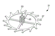
With reference to Fig. 5 to Fig. 7, show the manufacturing example according to the micromechanical parts of method 1.In the example depicted in fig. 5, visible clock and watch wheels 31, wheels 31 comprise pivotal axis 33, gear 35 and toothedly take turns 37.Method 1 can allow gear 35 for example for the part of the plate that obtains by electrodeposition technology, takes turns 37 then based on the plate that obtains by micro fabrication.
In the example depicted in fig. 6, visible clock and watch wheels 41, wheels 41 comprise that pivotal axis 43, gear 45 and two are toothed and take turns 47,49.Method 1 can allow gear 45 for example for the part of the plate that obtains by electrodeposition technology, takes turns 47,49 then based on the plate that obtains by micro fabrication.
Therefore advantageously, according to above-mentioned the first modification, gear 35,45 can also be integrated with axle 33,43 respectively, and forms can fix final part 31,41 integral body in the third step 7 of method 1.
Therefore be appreciated that and consider a plurality of micromechanical parts to be manufactured according to employed material, employed embodiment and/or selected modification.Therefore, as example ground, as shown in Figure 7, it is also conceivable that and make clock and watch escapement lever 51, it comprises pivotal axis 53, upper arm 55, main body 57 and jaw pin 55' and possible pin 53'.
Method 1 for example can allow escapement lever 51 to obtain by means of the part based on silicon only.This escapement lever 51 can be by obtaining by two plates micro fabrication manufacturing, that be stacked in step 5 on the support member 23 in step 3, upper arm 55 and jaw pin 55' are secured on the main body 57 by the gummed in step 7 by means of axle 53 and pin 53' respectively, come to discharge escapement lever 51 by apply power at axle 53 from described plate in final step 9.
Certainly, the invention is not restricted to shown example, but can have the various variants and modifications that it may occur to persons skilled in the art that.Especially, as shown with two-wire among Fig. 8, can in step 5, consider to be used at each stacking plate 11,13 etc. and/or encircle interstage 10 of deposition binder material between 30.If necessary, this binder material allows minor betterment fixing between at least two elements of final part.Binder material can deposit by the silk-screen printing technique that allows to deposit this binder material according to accurate thickness and area.
In addition, for the breakaway poing in the step 9 is provided, as shown in Figure 1, can require each material bridge 12,14 to be included in the cross section of part associated with it 19, the 21 end constrictions that connect.
Can also have more or 20,26 combinations of axle 22-recess still less.In addition, these recesses 20,26 can by plate 11 Already in, 13 part 19,21 and framework 15,17 between recess substitute.
At last, showing greatly vertically mode according to all members described above in each step installs just in order conveniently to understand the present invention.In fact, the member installation direction is not limited only to direction A, A' or C.In fact, for example in the situation that make escapement lever 51, can consider before step 5, among and come assembling fork watt from the plate 11 that is used to form part 57 and/or upper arm 55,13 etc. framework 15,17 etc. perforation side afterwards.In fact, the location of fork watt has very large importance, and the installation in stage 6 of step 5,8 etc. on support member 23 can be used for coming very accurately assembling fork watt along the direction that is approximately perpendicular to direction A, A', C.More generally, being appreciated that can be before step 5, among or afterwards at least one subdivision laterally is installed in the described part at least one with respect to described plate.
Claims (14)
1. the manufacture method (1) of a micromechanical parts (31,41,51) may further comprise the steps:
A) form (3) at least two plates (11,13) that comprise separately framework (15,17), described framework is connected with the part (19,21) of described part by at least one material bridge (12,14), and described part (19,21) comprises hole (16,18);
Described manufacture method is characterised in that further comprising the steps of:
B) at upper stacking (5) described at least two plates of support member (23), with stacking at least two described parts;
C) with pin (29) fixing (7) in each hole (16,18) of stacking described at least two parts, to form the part (31,41,51) with single pin, described pin at least one protrusion from stacking plate is in order to can be used as grip device;
D) from described two plates (11,13), discharge (9) formed part (31,41,51) at least.
2. the method for claim 1 (1) is characterized in that, for each plate (11,13), step b) may further comprise the steps:
E) by means of alignment device (25) guiding (B) described plate, so that described plate is directed reliably with respect to described support member (23);
F) described plate is slided at the axle (22) that at least one is fixed in described support member (23), until be resisted against on the shoulder (24) of described axle, so that described plate is placed reliably with respect to described support member (23).
3. method as claimed in claim 2 (1), it is characterized in that, in the described alignment device each comprises at least one oblique ring, described oblique ring is installed in the extension of described at least one axle of described support member (23), and be used for cooperating with recess (20,26), wherein said recess forms in each of described two plates in step a) at least.
4. method as claimed in claim 2 (1) is characterized in that, the guiding in the step e) realizes with at least two alignment devices (25), to improve reliability.
5. method as claimed in claim 3 (1) is characterized in that, each recess (20,26) forms at least in the framework (15,17) of described two plates.
6. method as claimed in claim 3 (1) is characterized in that, each recess corresponding in described at least two plates each described part (19,21) and the space between the framework (15,17).
7. the method for claim 1 (1) is characterized in that, each at least one material bridge (12,14) is included in the cross section of place, the end constriction that is connected with the described part of part, allows to produce the weakness zone that can make things convenient for step d) to carry out.
8. the method for claim 1 (1) is characterized in that, forms a plurality of parts (19,21) at each plate (11,13), to form a plurality of parts (31,41,51) in step c).
9. the method for claim 1 (1) is characterized in that, pin (29) extends by the handle that comprises pivot in its each end, to form pivotal axis.
10. the method for claim 1 (1) is characterized in that, pin (29) comprises ring (30) coaxially, and described ring is used for as retainer, to limit described pin entering in described hole.
11. method as claimed in claim 10 (1) is characterized in that, described coaxial rings (30) comprises tooth, with formative gear.
12. the method for claim 1 (1) is characterized in that at least one in the described plate forms by means of electrodeposition technology in step a).
13. the method for claim 1 (1) is characterized in that at least one in the described plate forms by means of micro fabrication in step a).
14. the method for claim 1 (1) is characterized in that, at least one subdivision before step b), among or laterally be installed in the described part at least one with respect to described plate afterwards.
Applications Claiming Priority (3)
| Application Number | Priority Date | Filing Date | Title |
|---|---|---|---|
| EP08169687A EP2189854A1 (en) | 2008-11-21 | 2008-11-21 | Method for manufacturing a micromechanical part |
| EP08169687.4 | 2008-11-21 | ||
| PCT/EP2009/064639 WO2010057777A1 (en) | 2008-11-21 | 2009-11-04 | Method for making a micromechanical part |
Publications (2)
| Publication Number | Publication Date |
|---|---|
| CN102224464A CN102224464A (en) | 2011-10-19 |
| CN102224464B true CN102224464B (en) | 2013-04-24 |
Family
ID=40627233
Family Applications (1)
| Application Number | Title | Priority Date | Filing Date |
|---|---|---|---|
| CN2009801463741A Active CN102224464B (en) | 2008-11-21 | 2009-11-04 | Method for making a micromechanical part |
Country Status (9)
| Country | Link |
|---|---|
| US (1) | US8661681B2 (en) |
| EP (2) | EP2189854A1 (en) |
| JP (1) | JP5548692B2 (en) |
| KR (1) | KR20110086579A (en) |
| CN (1) | CN102224464B (en) |
| HK (1) | HK1163266A1 (en) |
| RU (1) | RU2498382C2 (en) |
| TW (1) | TWI520900B (en) |
| WO (1) | WO2010057777A1 (en) |
Families Citing this family (14)
| Publication number | Priority date | Publication date | Assignee | Title |
|---|---|---|---|---|
| EP2400352A1 (en) | 2010-06-22 | 2011-12-28 | The Swatch Group Research and Development Ltd. | Escapement system for a timepiece |
| WO2012010408A1 (en) * | 2010-07-19 | 2012-01-26 | Nivarox-Far S.A. | Oscillating mechanism with elastic pivot and mobile for the transmission of energy |
| WO2013093108A1 (en) * | 2011-12-22 | 2013-06-27 | CSEM Centre Suisse d'Electronique et de Microtechnique SA - Recherche et Développement | Method for freeing a micromechanical part and a micromechanical part comprising sacrificial fasteners |
| CH706220B1 (en) * | 2012-03-06 | 2022-05-31 | Sigatec Sa | Method for assembling a fragile component on a metal part and micromechanical part assembled according to this method. |
| US9151259B2 (en) * | 2012-06-11 | 2015-10-06 | Continental Automotive Systems, Inc. | Stepped orifice hole |
| DE212014000091U1 (en) * | 2013-03-22 | 2015-10-23 | Omega Sa | Coaxial one-piece escapement anchor |
| EP2799939A1 (en) * | 2013-04-30 | 2014-11-05 | Universo S.A. | Support for the treatment of micromechanical parts |
| EP3083487B1 (en) | 2013-12-20 | 2020-01-08 | Rolex Sa | Method for manufacturing a timepiece component |
| EP2942147B1 (en) * | 2014-05-08 | 2018-11-21 | Nivarox-FAR S.A. | Clock escapement mechanism without lubrication |
| CH710543A2 (en) * | 2014-12-19 | 2016-06-30 | Omega Sa | Process for producing a decorated element of a timepiece or jewelery, and element produced by the method. |
| EP3109199B1 (en) * | 2015-06-25 | 2022-05-11 | Nivarox-FAR S.A. | Silicon-based part with at least one chamfer and method for manufacturing same |
| WO2017200621A2 (en) | 2016-02-29 | 2017-11-23 | The Regents Of The University Of Michigan | Assembly processes for three-dimensional microstructures |
| JP6743619B2 (en) * | 2016-09-23 | 2020-08-19 | セイコーエプソン株式会社 | Method of manufacturing mechanical part and method of manufacturing timepiece |
| EP3543795A1 (en) * | 2018-03-20 | 2019-09-25 | Patek Philippe SA Genève | Method for manufacturing silicon clock components |
Citations (5)
| Publication number | Priority date | Publication date | Assignee | Title |
|---|---|---|---|---|
| CH276772A (en) * | 1948-12-31 | 1951-07-31 | Bulova Watch Co Inc New York S | A method of manufacturing anchor wheels for anchor escapements. |
| EP0994398A1 (en) * | 1998-10-15 | 2000-04-19 | Eta SA Fabriques d'Ebauches | Method for manufacturing a gear wheel for a timepiece and gear wheel manufactured by said method |
| EP1035453B1 (en) * | 1999-03-05 | 2004-06-02 | ETA SA Manufacture Horlogère Suisse | Dial comprising brilliants, applied ornaments or other attached elements and process for fixing such elements onto such a dial |
| CN1906983A (en) * | 2004-01-15 | 2007-01-31 | 国际商业机器公司 | Micro-electromechanical sub-assembly having an on-chip transfer mechanism |
| EP1921042A1 (en) * | 2006-11-10 | 2008-05-14 | ETA SA Manufacture Horlogère Suisse | Fabrication of multilevel micromechanical silicon components |
Family Cites Families (25)
| Publication number | Priority date | Publication date | Assignee | Title |
|---|---|---|---|---|
| US640546A (en) * | 1898-11-01 | 1900-01-02 | Philo F Dresser | Hand-plane. |
| US4400861A (en) * | 1981-11-27 | 1983-08-30 | Oyo Instruments, Inc. | Fabrication of seismic springs from sheets |
| US5847537A (en) * | 1996-10-19 | 1998-12-08 | Parmley, Sr.; Daniel W. | Electric vehicle charging station system |
| JPH1148342A (en) * | 1997-08-05 | 1999-02-23 | Sumitomo Heavy Ind Ltd | Manufacture of micromachine |
| CN1170211C (en) * | 1998-07-03 | 2004-10-06 | 时至准钟表股份有限公司 | Method of manufacturing hand for analog electronic timepiece |
| DE60036603T2 (en) * | 2000-03-27 | 2008-07-03 | Vaucher Manufacture Fleurier S.A. | Display mechanism of the power reserve of a watch and clock provided with this mechanism |
| US6396239B1 (en) * | 2001-04-06 | 2002-05-28 | William M. Benn | Portable solar generator |
| US6755225B1 (en) * | 2003-01-24 | 2004-06-29 | Quantum Fuel Systems Technologies Worldwide, Inc. | Transportable hydrogen refueling station |
| DE10317889B4 (en) * | 2003-04-17 | 2008-10-30 | GFD-Gesellschaft für Diamantprodukte mbH | Micromechanical component and method for its production |
| CH699813B1 (en) * | 2004-03-25 | 2010-05-14 | Pierre Kunz S A | Wheel intended to come into contact with a mobile or fixed element and its manufacturing method. |
| US7093626B2 (en) * | 2004-12-06 | 2006-08-22 | Ovonic Hydrogen Systems, Llc | Mobile hydrogen delivery system |
| SG124309A1 (en) * | 2005-01-25 | 2006-08-30 | Sony Corp | A material and uses thereof |
| EP1696286B1 (en) * | 2005-02-23 | 2010-12-29 | ETA SA Manufacture Horlogère Suisse | Shock-damping bearing for timepieces |
| CH696475A5 (en) * | 2005-05-12 | 2007-06-29 | Eta Sa Mft Horlogere Suisse | Body analog display crystalline material, timepiece provided with such a display element and method for its manufacture. |
| EP1826634A1 (en) * | 2006-02-28 | 2007-08-29 | Nivarox-FAR S.A. | Micromechanical element provided with form-locking opening for axle assembly |
| US7721751B1 (en) * | 2006-05-09 | 2010-05-25 | Timothy Perrien | Fuel dispensing system |
| ATE422068T1 (en) * | 2006-11-13 | 2009-02-15 | Eta Sa Mft Horlogere Suisse | DRIVE MODULE COMPRISING A MEMS MICROMOTOR, METHOD FOR PRODUCING THIS MODULE AND CLOCK EQUIPPED WITH THIS MODULE |
| US20080190748A1 (en) * | 2007-02-13 | 2008-08-14 | Stephen Daley Arthur | Power overlay structure for mems devices and method for making power overlay structure for mems devices |
| US8299645B2 (en) * | 2007-07-27 | 2012-10-30 | Skybuilt Power | Renewable energy trailer |
| US20090187416A1 (en) * | 2008-01-17 | 2009-07-23 | Clean Emission Fluids, Inc. | Fuel Station Apparatus and Method for Utilizing the Same |
| JP5300275B2 (en) | 2008-01-25 | 2013-09-25 | キヤノン株式会社 | Method for manufacturing metal member having a plurality of protrusions |
| CH699110A1 (en) * | 2008-07-10 | 2010-01-15 | Swatch Group Res & Dev Ltd | Mechanical component i.e. escape wheel, fabricating method for timepiece, involves assembling attachment on component such that component is ready to be mounted without requiring to touch component, and liberating component from substrate |
| US8294286B2 (en) * | 2008-07-15 | 2012-10-23 | F3 & I2, Llc | Network of energy generating modules for transfer of energy outputs |
| US8295033B2 (en) * | 2010-01-21 | 2012-10-23 | George Van Straten | Mobile electricity generator using solar, wind, and fuel-generated power |
| US8899627B2 (en) * | 2011-01-13 | 2014-12-02 | Wacker Neuson Production Americas Llc | Multiple fuel tank system |
-
2008
- 2008-11-21 EP EP08169687A patent/EP2189854A1/en not_active Withdrawn
-
2009
- 2009-11-04 JP JP2011536816A patent/JP5548692B2/en active Active
- 2009-11-04 CN CN2009801463741A patent/CN102224464B/en active Active
- 2009-11-04 KR KR1020117012439A patent/KR20110086579A/en not_active Application Discontinuation
- 2009-11-04 WO PCT/EP2009/064639 patent/WO2010057777A1/en active Application Filing
- 2009-11-04 RU RU2011125301/28A patent/RU2498382C2/en active
- 2009-11-04 US US13/130,698 patent/US8661681B2/en active Active
- 2009-11-04 EP EP09751882.3A patent/EP2359197B1/en active Active
- 2009-11-16 TW TW098138859A patent/TWI520900B/en active
-
2012
- 2012-04-13 HK HK12103667.2A patent/HK1163266A1/en unknown
Patent Citations (5)
| Publication number | Priority date | Publication date | Assignee | Title |
|---|---|---|---|---|
| CH276772A (en) * | 1948-12-31 | 1951-07-31 | Bulova Watch Co Inc New York S | A method of manufacturing anchor wheels for anchor escapements. |
| EP0994398A1 (en) * | 1998-10-15 | 2000-04-19 | Eta SA Fabriques d'Ebauches | Method for manufacturing a gear wheel for a timepiece and gear wheel manufactured by said method |
| EP1035453B1 (en) * | 1999-03-05 | 2004-06-02 | ETA SA Manufacture Horlogère Suisse | Dial comprising brilliants, applied ornaments or other attached elements and process for fixing such elements onto such a dial |
| CN1906983A (en) * | 2004-01-15 | 2007-01-31 | 国际商业机器公司 | Micro-electromechanical sub-assembly having an on-chip transfer mechanism |
| EP1921042A1 (en) * | 2006-11-10 | 2008-05-14 | ETA SA Manufacture Horlogère Suisse | Fabrication of multilevel micromechanical silicon components |
Also Published As
| Publication number | Publication date |
|---|---|
| HK1163266A1 (en) | 2012-09-07 |
| CN102224464A (en) | 2011-10-19 |
| EP2359197B1 (en) | 2015-01-07 |
| RU2498382C2 (en) | 2013-11-10 |
| TWI520900B (en) | 2016-02-11 |
| US20110225801A1 (en) | 2011-09-22 |
| JP5548692B2 (en) | 2014-07-16 |
| RU2011125301A (en) | 2012-12-27 |
| EP2359197A1 (en) | 2011-08-24 |
| EP2189854A1 (en) | 2010-05-26 |
| US8661681B2 (en) | 2014-03-04 |
| TW201029913A (en) | 2010-08-16 |
| KR20110086579A (en) | 2011-07-28 |
| JP2012509197A (en) | 2012-04-19 |
| WO2010057777A1 (en) | 2010-05-27 |
Similar Documents
| Publication | Publication Date | Title |
|---|---|---|
| CN102224464B (en) | Method for making a micromechanical part | |
| JP5457608B2 (en) | Clock face holder | |
| KR20110139110A (en) | Single piece wheel set for a timepiece | |
| CN101625542A (en) | Method of manufacturing a micromechanical part | |
| TW201007394A (en) | One-piece double balance spring and method of manufacturing the same | |
| CN101831672A (en) | The method that is used for the mould of electrocasting and makes this mould | |
| KR20120005398A (en) | Method of manufacturing glass substrate with through electrode and method of manufacturing electronic component | |
| TW201732465A (en) | Composite component with stressed resilient means | |
| JP3203513U (en) | Coaxial escapement integrated ankle | |
| JP5055020B2 (en) | Linked laminated core, armature manufacturing method, and progressive mold apparatus | |
| CH698562B1 (en) | A process for producing a piezoelectric vibrating body, the piezoelectric vibrating body, the piezoelectric vibrator oscillator, electronic device, radio controlled clock and wafer. | |
| US6711802B2 (en) | Method of manufacturing multi-core ferrule | |
| KR101457289B1 (en) | Method for producing a watchmaking component comprising at least two parts | |
| CN112442714A (en) | Method for decorating a mechanical part | |
| CN104937503A (en) | Welded bimetal clock finishing component | |
| CN114101475A (en) | Ultrasonic impression forming method and forming equipment for high-temperature high-strength amorphous alloy micro-mold | |
| JPH06174943A (en) | Mounting for optical fiber | |
| CN109814364A (en) | The escapement lever of escapement for watch and clock movement | |
| US20100308475A1 (en) | Composite of at least two semiconductor substrates and a production method | |
| CN220462739U (en) | Swing rod welding mould | |
| CN220658091U (en) | Microporous sheet | |
| CN112846833B (en) | CNC (computer numerical control) finishing method for core component cavity of mobile phone jig | |
| JP5585343B2 (en) | Stator core manufacturing method | |
| KR100505534B1 (en) | A Machining And Brazing Methood Of Thin Metal Plate With Micro Flow Path And Pattern | |
| CN109411453A (en) | A kind of perpendicular interconnection method of 3 D stereo encapsulation |
Legal Events
| Date | Code | Title | Description |
|---|---|---|---|
| C06 | Publication | ||
| PB01 | Publication | ||
| C10 | Entry into substantive examination | ||
| SE01 | Entry into force of request for substantive examination | ||
| REG | Reference to a national code |
Ref country code: HK Ref legal event code: DE Ref document number: 1163266 Country of ref document: HK |
|
| C14 | Grant of patent or utility model | ||
| GR01 | Patent grant | ||
| REG | Reference to a national code |
Ref country code: HK Ref legal event code: GR Ref document number: 1163266 Country of ref document: HK |