CN101973096B - Secondary vulcanization forming device of rubber diaphragms for brake chamber in automobiles - Google Patents
Secondary vulcanization forming device of rubber diaphragms for brake chamber in automobiles Download PDFInfo
- Publication number
- CN101973096B CN101973096B CN201010287530A CN201010287530A CN101973096B CN 101973096 B CN101973096 B CN 101973096B CN 201010287530 A CN201010287530 A CN 201010287530A CN 201010287530 A CN201010287530 A CN 201010287530A CN 101973096 B CN101973096 B CN 101973096B
- Authority
- CN
- China
- Prior art keywords
- cope match
- lifting device
- plate pattern
- template
- plate
- Prior art date
- Legal status (The legal status is an assumption and is not a legal conclusion. Google has not performed a legal analysis and makes no representation as to the accuracy of the status listed.)
- Active
Links
Images


Landscapes
- Heating, Cooling, Or Curing Plastics Or The Like In General (AREA)
Abstract
The invention discloses a secondary vulcanization forming device of rubber diaphragms for a brake chamber in automobiles, which comprises a vacuum vulcanizing press and a mould operating mechanism, wherein the vacuum vulcanizing press is provided with a working bedplate which can slide in and out of the vacuum vulcanizing press, and vulcanization forming moulds are arranged on the working bedplate; the vulcanization forming moulds comprise a lower template, a middle template and an upper template, and the lower template is fixed on the working bedplate; the mould operating mechanism comprises a frame, the frame is provided with a supporting structure, and the working bedplate after sliding out of the vacuum vulcanizing press is fixed on the supporting structure; the frame is also provided with an upper-template lifting device and a middle-template lifting device, and the two lifting devices can respectively lift the upper template and the middle template of the modules. Through setting the mould operating mechanism matched with the vacuum vulcanizing press, in the invention, the problem of arranging compression rings and replacing top dies by manual labors in the prior art is solved, the conditions for producing duplicating diaphragms of rubber diaphragms are created, the device availability and the production efficiency are improved, and condition for production safety is also provided.
Description
Technical field
The present invention relates to a kind of rubber diaphragm of automobile brake chamber post-cure shaped device.
Background technology
Shown in Figure 1 is rubber diaphragm of automobile brake chamber post-cure moulding press at present commonly used, the counterdie 4 in the mould ' be fixed on press platen 5 ' on.
During production, the operating process of this sulfidization molding press is:
1) with platen 5 ' pull out press, in counterdie 4 ' die cavity, put into once sulfuration and use sizing material, above sizing material, cover canvas, on canvas, overlap upper press ring 3 ', put once vulcanize patrix 2 ', with platen 5 ' push press, carry out the once sulfuration of diaphragm of rubber;
2) with platen 5 ' pull out press; Take off once vulcanize patrix 2 ', in counterdie 4 ' die cavity, place post-cure in type barrier film lower glue layer and the canvas and use sizing material, put post-cure patrix 6 '; With platen 5 ' push press, carry out the post-cure of diaphragm of rubber;
3) with platen 5 ' pull out press, take off post-cure patrix 6 ' with pressure ring 3 ' after, take out the diaphragm of rubber finished product.
Repeat said process, accomplish the batch process of diaphragm of rubber.
Because in the above-mentioned sulfidization molding press course of work; Rely on manpower to carry out pushing, pulling out of press platen, rely on manpower to accomplish the replacing of taking off, laying of pressure ring and two patrixes, take off and lay, therefore; Exist labor strength big, the defective that production efficiency is low.
Summary of the invention
Deficiency to the prior art existence; The object of the present invention is to provide a kind of rubber diaphragm of automobile brake chamber post-cure shaped device; This shaped device is equipped with Mould operation mechanism on known vacuum vulcanizing press basis, realized laying automatically of patrix, middle mould in the mould; And the quick conversion of once vulcanizing patrix and post-cure patrix, thereby for the multiple mould production of diaphragm of rubber, improve equipment capacity, enhance productivity and created condition.
For realizing above-mentioned purpose, rubber diaphragm of automobile brake chamber post-cure shaped device of the present invention comprises vacuum vulcanization press and Mould operation mechanism; Have the working plate that can slide into, skid off press on the said vacuum vulcanization press along its track; The diaphragm of rubber curing forming mold is installed on the working plate, bottom-up lower bolster, middle template, the cope match-plate pattern of comprising successively of this mould, wherein; Lower bolster is fixed on the working plate; Lower bolster is provided with counterdie, and middle template is provided with pressure ring, and it is right that cope match-plate pattern is provided with patrix; Each patrix forms with the back-to-back concentric arrangement of patrix with patrix and a post-cure once vulcanizing by one, and counterdie, pressure ring, patrix are to match one by one; Said Mould operation mechanism comprises frame; Frame is provided with accepts structure; Said working plate skids off and is positioned at this behind the press and accepts on the structure, also is provided with cope match-plate pattern lifting device and middle template lifting device on the frame, curing forming mold through working plate be positioned at accept on the structure after; Said two lifting devices can carry out descending operation to cope match-plate pattern in the mould and middle template respectively; Wherein, the cope match-plate pattern after being raised can be around the upset of its gyroaxis, and accomplishes the replacing of patrix centering two patrixes in once sulfuration and post-cure operation through upset.
Further; Said working plate is installed on the horizontal rail that is provided with in the said press; And press is provided with and is used to drive the drive unit that working plate slided into, skidded off press, and this drive unit is cylinder or hydraulic cylinder, or the driving mechanism that is made up of tooth bar, gear, motor.
Further, said curing forming mold is the multiple mode structure that includes some cover curing forming molds unit, and the counterdie in each unit, pressure ring, patrix are to being separately positioned on said lower bolster, middle template and the cope match-plate pattern.
Further, said frame comprises base, and the said structure of accepting is arranged on this base, accepts structure and accepts track by level and constitute, and said working plate can directly slide into this from said press and accept on the track; With the working plate glide direction is fore-and-aft direction, accepts track left and right sides branch and shows guide upright post, and said cope match-plate pattern lifting device and middle template lifting device can move up and down and be installed on the guide upright post; Cope match-plate pattern lifting device below has the spaced apart lower suspension of a pair of left and right directions; Two lower suspension lower ends respectively carry a supporting plate; Two splint upper surfaces be provided with separately an opening upwards, along the horizontally extending half slot of left and right directions; Two half slots are concentric each other, and correspondingly, limit, the cope match-plate pattern left and right sides is provided with that a pair of and said half slot is complementary and concentric spindle nose each other; Middle template lifting device comprises a left tray and a right carriage; Left tray right side and right carriage left side are provided with a horizontal support limit along the fore-and-aft direction extension separately; Correspondingly, be respectively arranged with the horizontal braces that matches with said horizontal support limit on the limit, the middle template left and right sides; Cope match-plate pattern lifting device and middle template lifting device slide up and down along guide upright post by cylinder that is provided with on the frame or Driven by Hydraulic Cylinder; The cope match-plate pattern lifting device has three operating positions, upper, middle and lower; Middle template lifting device has upper and lower two operating positions, limits by travel switch that is provided with on the frame or position sensor; When cope match-plate pattern lifting device and middle template lifting device are positioned at minimum separately operating position; Working plate skids off press and the level of navigating to is accepted on the track; At this moment, the spindle nose on the cope match-plate pattern dual-side just be positioned at a pair of half slot directly over, the horizontal braces on the middle template dual-side then be positioned at a pair of horizontal support limit directly over; On move the cope match-plate pattern lifting device; Spindle nose on the cope match-plate pattern dual-side makes it be raised the disengaging lower bolster with falling into two half slots respectively, on move in the template lifting device, the horizontal support limit on the left and right carriage promotes with the below of horizontal braces on the template dual-side in being supported on respectively and with middle template and breaks away from lower bolster; , the cope match-plate pattern lifting device during operating position, can carry out turning operation between being positioned at wherein to cope match-plate pattern.
Further, said spindle nose is positioned on the said cope match-plate pattern left and right directions center line.
Further, the left and right carriage in said in the template lifting device is drive separately.
Further; The said track of accepting each side is provided with two guide upright posts; Four guide upright posts lay respectively on four summits of rectangle, and the column top interconnects fixing through top board, constitute one or four column frame structures thus; And the base of this four column frames structure is connected fixing respectively with the top with said press; The driving cylinder of said cope match-plate pattern lifting device or hydraulic cylinder are arranged on this top board, and the driving cylinder or the hydraulic cylinder of left and right carriage are arranged on the said base in the said middle template lifting device.
Further, said guide upright post middle part is provided with a horizontal baffle, and said level is accepted rail supported and is fixed on this horizontal baffle; Accept track and constitute, respectively be provided with the support roller that row are arranged along fore-and-aft direction on the two support plate opposite flanks, with horizontally extending channel section gathering sill by the support plate that extends along fore-and-aft direction that a pair of interval is arranged on the said horizontal baffle; The support roller gyroaxis is horizontally disposed with along left and right directions; Two be disbursed from the cost and expenses the support roller supporting surface be positioned at same horizontal plane, and channel section gathering sill downside is lower than the support roller supporting surface in vertical direction; When said working plate skids off said press; Its bottom supporting is on support roller, and its dual-side inserts respectively in the channel section gathering sill on two support plates, under the gathering sill guiding, continues to move and finally be positioned on two support plates.
Further; Horizontal braces in said on the limit, the template left and right sides is by two sections formations that are provided with at interval; The middle part on the horizontal support limit on the said left and right carriage all has a boss, and the spacing between two sections of this land length and each horizontal braces is suitable, during left and right carriage promotes during template; The boss at its middle part, horizontal support limit is inserted in two sections intervals between the horizontal braces location of realizing centering template fore-and-aft direction thus; The spacing on the said cope match-plate pattern lifting device between the two lower suspension lower end supporting plate relative sides and the width of said cope match-plate pattern left and right directions are suitable; The spacing on the left and right carriage between the two horizontal support limit relative sides and the width of middle template left and right directions are suitable, realize thus the cope match-plate pattern after promoting and the location of middle template left and right directions.
After the present invention passes through setting and vacuum vulcanization press mold matched operating mechanism; Improved the automaticity that diaphragm of rubber is produced; Eliminated and relied on manpower to lay pressure ring and the problem of changing patrix in the past; Be the multiple mould production of diaphragm of rubber,, also created condition simultaneously for safety in production for improving utilization rate of equipment and installations, enhancing productivity and created condition.
Description of drawings
Fig. 1 is existing rubber diaphragm of automobile brake chamber post-cure moulding press structural representation;
Fig. 2 is a rubber diaphragm of automobile brake chamber post-cure shaped device structural representation of the present invention;
Fig. 3 is state one front view of Mould operation mechanism shown in the sequence number 2 among Fig. 2;
Fig. 4 is Mould operation mechanism state two front views;
Fig. 5 is Mould operation mechanism state three front views;
Fig. 6 is a used multiple mould die face view in apparatus of the present invention;
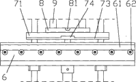
Fig. 7 is a Mould operation mechanism front partial enlarged view;
Fig. 8 be among Fig. 7 A to view;
Fig. 9 is a middle template lateral plan shown in the sequence number 21 among Fig. 6.
The specific embodiment
Specify the present invention below in conjunction with accompanying drawing.
As shown in Figure 2, rubber diaphragm of automobile brake chamber post-cure shaped device of the present invention comprises vacuum vulcanization press 1 and Mould operation mechanism 2.Vacuum (-tight) housing 13 and working plate 15 (referring to Fig. 3) be equipped with on vacuum vulcanization press 1 seaming chuck; Diaphragm of rubber curing forming mold 19 (referring to Fig. 6) is installed on the working plate 15, and vacuum (-tight) housing 13 is buckled on the working plate 15 through cover and constitutes vacuum chamber jointly with working plate.Working plate 15 is installed on the horizontal rail (not shown) that is provided with on the press; Simultaneously; Press is provided with working plate 15 and drives cylinder or hydraulic cylinder 14, and working plate 15 can slide into, skid off press by fore-and-aft direction shown in the arrow B among the figure along its track under cylinder or hydraulic cylinder 14 drivings.
Like Fig. 3-shown in Figure 6; Diaphragm of rubber curing forming mold 19 is for including the multiple mode structure of 4 cover diaphragm of rubber curing forming mold unit; Comprise lower bolster 20, middle template 21, cope match-plate pattern 22 from top to bottom successively; 4 counterdies 201 in the 4 cover curing forming mold unit are arranged on the lower bolster 20; On the template 21,4 patrixes were to being arranged on the cope match-plate pattern 22 during 4 pressure rings 212 were arranged on, and each patrix forms with patrix 222 back-to-back arranged coaxial with patrix 223 and a post-cure once vulcanizing by one.Lower bolster 20, middle template 21, cope match-plate pattern 22 and working plate 15 are rectangle, and lower bolster 20 is fixed with working plate 15 centerings, and make entire die 19 and the configuration of working plate 15 centerings thus.
Mould operation mechanism 2 is typical four column frame structures, comprises base 3, and base 3 is provided with 11, four guide upright post 11 upper ends of four guide upright posts and interconnects fixingly through top board 23, and four guide upright posts 11 are positioned on four summits of rectangle.The base 3 and the press base of Mould operation mechanism 2 are fixedly connected, and top and press top are fixedly connected.
Referring to Fig. 7, Fig. 8; Guide upright post 11 vertical direction middle part is fixed with a horizontal baffle 5 through lock nut, is arranged at intervals with a pair of support plate 6 on the horizontal baffle 5, is provided with the support roller 62 that row are arranged along fore-and-aft direction on each support plate 6; Together along the horizontally extending channel section gathering sill 61 of fore-and-aft direction; Two be disbursed from the cost and expenses the support roller 62 supporting surface be positioned on the same horizontal plane, channel section gathering sill opening is relative, and the gathering sill downside is lower than the supporting surface of support roller 62 in vertical direction.
Two support plates, 6 symmetry branches are listed in working plate 15 fore-and-aft direction center line both sides; The two support rollers 62 of being disbursed from the cost and expenses spatially mouthful join with skidding off of vacuum vulcanization press upper table plate 15; And support roller horizontal support face flushes with working plate 15 lower surfaces, and the spacing between two gathering sills, 61 bottom lands and the width of working plate left and right directions are complementary, like this; Working plate 15 can directly move on two support plates 6 on the track from press under cylinder or hydraulic cylinder 14 drivings.When support plate 6 moved, working plate 15 lower surfaces were supported on the support roller 62 from press, and then insert in the gathering sill 61 on the support plate 6 on its limit, left and right sides, and under gathering sill 61 guiding rectilinear translation and being positioned on two support plates 6.
Limit, working plate 15 left and right sides all has a plug side 151, and this plug side lower surface flushes with the whole lower surface of working plate 15, and upper surface then is lower than the upper surface of its inboard working plate; The width of two plug sides, 151 left and right directions is greater than the degree of depth or the mutual coupling of gathering sill 61, and the spacing on the thickness of plug side 151 vertical direction and the support plate 6 between support roller 62 supporting surfaces and gathering sill 61 upper sides is complementary; Like this; After plug side 151 inserts in the gathering sill 61; Except utilizing gathering sill 61 bottom lands to match with plug side 151 side elevations outside mobile guiding the to working plate 15 fore-and-aft directions, gathering sill 61 upper sides also match with plug side 151 upper surfaces to prevent to move on the working plate 15 and break away from support roller 62 supporting surfaces.
The guide upright post 11 of horizontal baffle 5 tops is provided with cope match-plate pattern lifting device and middle template lifting device 7; Wherein, The cope match-plate pattern lifting device is made up of the horizontal supporting plate 8 of crossbeam 10, the two pairs of vertical links that left and right directions is provided with at interval 9 and vertical links lower end; The every pair of vertical links 9 constitutes a lower suspension with the horizontal supporting plate 8 of its lower end, be provided with on two horizontal supporting plates 8 opening upwards, along the horizontally extending half slot 81 of left and right directions, and two half slots 81 are each other with one heart.The spacing between two horizontal supporting plate 8 adjacent side and the width of cope match-plate pattern 22 left and right directions are complementary; Simultaneously; Correspondingly, cope match-plate pattern 22 left and right directions dual-sides are provided with spindle nose 221, two spindle noses 221 that a pair of and half slot 81 match and are positioned on the center line of cope match-plate pattern left and right directions.
Middle template lifting device 7 is formed with the right gripper shoe 72 that is installed on two right side guide upright posts 11 by being installed in two left gripper shoes 71 on the guide upright post 11 of left side; Respectively be provided with a horizontal support limit 73 on left side gripper shoe 71 right edge and right gripper shoe 72 left side; Spacing and the width of middle template 21 left and right directions that these 73 fore-and-aft direction centre positions, horizontal support limit are provided with between a boss 74, the two horizontal support limits 73 are complementary.Correspondingly; In respectively be provided with the horizontal braces 211 that matches with horizontal support limit 73 respectively on the template 21 left and right directions dual-sides; Referring to Fig. 9, each horizontal braces 211 includes two sections that are provided with at interval, and the boss 74 on spacing between two sections and the horizontal support limit 73 is complementary.
The cope match-plate pattern lifting device drives and slides up and down along guide upright post 11 by being installed in cylinder or hydraulic cylinder 12 on the top board 23, and the left and right sides gripper shoe 71,72 in the middle template lifting device 7 drives and slides up and down along guide upright post 11 by being arranged on two cylinders or hydraulic cylinder 4 on the base respectively.
The cope match-plate pattern lifting device has three operating positions, upper, middle and lower along guide upright post 11; Middle template lifting device has upper and lower two operating positions along guide upright post 11; Each operating position of two lifting devices limits by the travel switch or the optoelectronic switch 17 that are provided with on the support 16 that is fixed on the top board 23, is provided with the support 18 with travel switch or optoelectronic switch 17 cooperatings on the crossbeam 10 in the cope match-plate pattern lifting device and on the middle template lifting device 7.
When cope match-plate pattern lifting device and middle template lifting device all are positioned at separately the operating position, below; Working plate 15 skids off and is positioned on the support plate 6 from press under cylinder or hydraulic cylinder 14 drivings; Along with working plate 15 moves on support plate 6; Cope match-plate pattern 22 in the diaphragm of rubber curing forming mold 19 that is provided with on it and middle template 21 is together taken between cope match-plate pattern lifting device two lower suspensions respectively and the left and right sides gripper shoe 71 of middle template lifting device 7, between 72; And along with working plate 15 finally is positioned on the support plate 6; Spindle nose 221 on the cope match-plate pattern 22 just be positioned at half slot 81 directly over, the space between two sections of each horizontal braces on the middle template 21 just be positioned at horizontal support limit 73 convex platforms 74 directly over.After this, on move the cope match-plate pattern lifting device, the spindle nose 221 on the cope match-plate pattern 22 will fall into half slot 81 and drive cope match-plate pattern 22 up disengaging templates 21 and lower bolsters 20 thus; On move in template lifting device 7, the horizontal support limit 73 on the left and right sides gripper shoe 71,72 will be supported on horizontal braces 211 lower surfaces and template 21 up disengaging lower bolsters 20 in driving.
Because cope match-plate pattern 22 is supported on the cope match-plate pattern lifting device through spindle nose 221, therefore, on its lifting device, cope match-plate pattern 22 can be around its gyroaxis 221 upsets.And, spindle nose 221 is arranged on the center line of cope match-plate pattern 22 left and right directions, cope match-plate pattern 22 is reversed, to reduce turning operation power as far as possible under the state that keeps balance.
In addition; Because the width of cope match-plate pattern 22 left and right directions and the spacing between two supporting plates 8 are complementary; The width of middle template 21 left and right directions and the spacing between the two horizontal support limits 73 are complementary; Cope match-plate pattern 22 is supported in the half slot 81 on two supporting plates 8 through spindle nose 221, during the boss 74 on the horizontal support limit 73 is fitted on the template 21 in the interval between two sections of each horizontal braces, therefore; Cope match-plate pattern 22 all is raised under the limited situation all around with middle template 21, and it is accurately equipped once more to guarantee down to fall behind the upper, middle and lower mould like this.
The said apparatus operating process is following:
1. at state shown in Figure 2, diaphragm of rubber curing forming mold 19 is positioned in the Mould operation mechanism 2 with vacuum vulcanization press bed plate 15, and at this moment, cope match-plate pattern lifting device and middle template lifting device all are positioned at minimum separately operating position;
2. operate cylinder or hydraulic cylinder 12,4, order promotes the cope match-plate pattern lifting device and middle template lifting device arrives the highest separately operating position shown in Figure 4, takes out molded good diaphragm of rubber product each counterdie 201 from lower bolster 20; In counterdie 201, put into sizing material and canvas, the template lifting device is placed to middle template 21 on the lower bolster 20 to its minimum operating position in moving down; Move down the cope match-plate pattern lifting device to its intermediate position shown in Figure 5; Upset cope match-plate pattern 22 makes once sulfuration with patrix 223 down, moves down the cope match-plate pattern lifting device once more to its minimum operating position; Make cope match-plate pattern 22 and lower bolster 20 matched moulds; Manipulating cylinder or hydraulic cylinder 14 are recovered to working plate 15 in the vacuum vulcanization press, carry out a vulcanization process of diaphragm of rubber;
3. after vulcanization process was accomplished, working plate 15 was seen off press once more and is positioned in the Mould operation mechanism, on move the cope match-plate pattern lifting device to its intermediate position shown in Figure 5; Upset cope match-plate pattern 22; Make post-cure down, in counterdie, put into sizing material, move down the cope match-plate pattern lifting device to its minimum operating position with patrix 222; After making cope match-plate pattern 22 and lower bolster 20 matched moulds once more; Working plate 15 is recovered in the vacuum vulcanization press, carries out the post-cure operation of diaphragm of rubber, and accomplish a production process of diaphragm of rubber.
Constantly the above-mentioned production process of circulation promptly realizes the batch process of diaphragm of rubber.
Claims (9)
1. a rubber diaphragm of automobile brake chamber post-cure shaped device is characterized in that, comprises vacuum vulcanization press and Mould operation mechanism; Have the working plate that can slide into, skid off press on the said vacuum vulcanization press along its track; The diaphragm of rubber curing forming mold is installed on the working plate, bottom-up lower bolster, middle template, the cope match-plate pattern of comprising successively of this mould, wherein; Lower bolster is fixed on the working plate; Lower bolster is provided with counterdie, and middle template is provided with pressure ring, and it is right that cope match-plate pattern is provided with patrix; Each patrix forms with the back-to-back concentric arrangement of patrix with patrix and a post-cure once vulcanizing by one, and counterdie, pressure ring, patrix are to match one by one; Said Mould operation mechanism comprises frame; Frame is provided with accepts structure; Said working plate skids off and is positioned at this behind the press and accepts on the structure, also is provided with cope match-plate pattern lifting device and middle template lifting device on the frame, curing forming mold through working plate be positioned at accept on the structure after; Said two lifting devices can carry out descending operation to cope match-plate pattern in the mould and middle template respectively; Wherein, the cope match-plate pattern after being raised can be around the upset of its gyroaxis, and accomplishes the replacing of patrix centering two patrixes in once sulfuration and post-cure operation through upset.
2. rubber diaphragm of automobile brake chamber post-cure shaped device as claimed in claim 1; It is characterized in that; Said working plate is installed on the horizontal rail that is provided with in the said press; And press is provided with and is used to drive the drive unit that working plate slided into, skidded off press, and this drive unit is cylinder or hydraulic cylinder, or the driving mechanism that is made up of tooth bar, gear, motor.
3. rubber diaphragm of automobile brake chamber post-cure shaped device as claimed in claim 2; It is characterized in that; Said curing forming mold is the multiple mode structure that includes some cover curing forming molds unit, and the counterdie in each unit, pressure ring, patrix are to being separately positioned on said lower bolster, middle template and the cope match-plate pattern.
4. rubber diaphragm of automobile brake chamber post-cure shaped device as claimed in claim 3; It is characterized in that; Said frame comprises base; The said structure of accepting is arranged on this base, accepts structure and accepts track by level and constitute, and said working plate can directly slide into this from said press and accept on the track; With the working plate glide direction is fore-and-aft direction, accepts track left and right sides branch and shows guide upright post, and said cope match-plate pattern lifting device and middle template lifting device can move up and down and be installed on the guide upright post; Cope match-plate pattern lifting device below has the spaced apart lower suspension of a pair of left and right directions; Two lower suspension lower ends respectively carry a supporting plate; On two supporting plates upper surface be provided with separately an opening upwards, along the horizontally extending half slot of left and right directions; Two half slots are concentric each other, and correspondingly, limit, the cope match-plate pattern left and right sides is provided with that a pair of and said half slot is complementary and concentric spindle nose each other; Middle template lifting device comprises a left tray and a right carriage; Left tray right side and right carriage left side are provided with a horizontal support limit along the fore-and-aft direction extension separately; Correspondingly, be respectively arranged with the horizontal braces that matches with said horizontal support limit on the limit, the middle template left and right sides; Cope match-plate pattern lifting device and middle template lifting device slide up and down along guide upright post by cylinder that is provided with on the frame or Driven by Hydraulic Cylinder; The cope match-plate pattern lifting device has three operating positions, upper, middle and lower; Middle template lifting device has upper and lower two operating positions, limits by travel switch that is provided with on the frame or position sensor; When cope match-plate pattern lifting device and middle template lifting device are positioned at minimum separately operating position; Working plate skids off press and the level of navigating to is accepted on the track; At this moment, the spindle nose on the cope match-plate pattern dual-side just be positioned at a pair of half slot directly over, the horizontal braces on the middle template dual-side then be positioned at a pair of horizontal support limit directly over; On move the cope match-plate pattern lifting device; Spindle nose on the cope match-plate pattern dual-side makes it be raised the disengaging lower bolster with falling into two half slots respectively, on move in the template lifting device, the horizontal support limit on the left and right carriage promotes with the below of horizontal braces on the template dual-side in being supported on respectively and with middle template and breaks away from lower bolster; , the cope match-plate pattern lifting device during operating position, can carry out turning operation between being positioned at wherein to cope match-plate pattern.
5. rubber diaphragm of automobile brake chamber post-cure shaped device as claimed in claim 4 is characterized in that, said spindle nose is positioned on the said cope match-plate pattern left and right directions center line.
6. rubber diaphragm of automobile brake chamber post-cure shaped device as claimed in claim 5 is characterized in that, the left and right carriage in the said middle template lifting device is drive separately.
7. rubber diaphragm of automobile brake chamber post-cure shaped device as claimed in claim 6; It is characterized in that the said track of accepting each side is provided with two guide upright posts, four guide upright posts lay respectively on four summits of rectangle; The column top interconnects fixing through top board; Constitute one or four column frame structures thus, and the base of this four column frames structure is connected with said press respectively with the top fixing; The driving cylinder of said cope match-plate pattern lifting device or hydraulic cylinder are arranged on this top board, and the driving cylinder or the hydraulic cylinder of left and right carriage are arranged on the said base in the said middle template lifting device.
8. rubber diaphragm of automobile brake chamber post-cure shaped device as claimed in claim 7 is characterized in that, said guide upright post middle part is provided with a horizontal baffle; Said level is accepted rail supported and is fixed on this horizontal baffle; Accept track and constitute, respectively be provided with the support roller that row are arranged along fore-and-aft direction on the two support plate opposite flanks, with horizontally extending channel section gathering sill by the support plate that extends along fore-and-aft direction that a pair of interval is arranged on the said horizontal baffle; The support roller gyroaxis is horizontally disposed with along left and right directions; Two be disbursed from the cost and expenses the support roller supporting surface be positioned at same horizontal plane, and channel section gathering sill downside is lower than the support roller supporting surface in vertical direction; When said working plate skids off said press; Its bottom supporting is on support roller, and its dual-side inserts respectively in the channel section gathering sill on two support plates, under the gathering sill guiding, continues to move and finally be positioned on two support plates.
9. device as claimed in claim 6; It is characterized in that the horizontal braces on the said middle limit, the template left and right sides is by two sections formations that are provided with at interval, the middle part on the horizontal support limit on the said left and right carriage all has a boss; Spacing between two sections of this land length and each horizontal braces is suitable; During template, the boss at its middle part, horizontal support limit was inserted in two sections intervals between the horizontal braces location of realizing centering template fore-and-aft direction thus during left and right carriage promoted; The spacing on the said cope match-plate pattern lifting device between the two lower suspension lower end supporting plate relative sides and the width of said cope match-plate pattern left and right directions are suitable; The spacing on the left and right carriage between the two horizontal support limit relative sides and the width of middle template left and right directions are suitable, realize thus the cope match-plate pattern after promoting and the location of middle template left and right directions.
Priority Applications (1)
| Application Number | Priority Date | Filing Date | Title |
|---|---|---|---|
| CN201010287530A CN101973096B (en) | 2010-09-20 | 2010-09-20 | Secondary vulcanization forming device of rubber diaphragms for brake chamber in automobiles |
Applications Claiming Priority (1)
| Application Number | Priority Date | Filing Date | Title |
|---|---|---|---|
| CN201010287530A CN101973096B (en) | 2010-09-20 | 2010-09-20 | Secondary vulcanization forming device of rubber diaphragms for brake chamber in automobiles |
Publications (2)
| Publication Number | Publication Date |
|---|---|
| CN101973096A CN101973096A (en) | 2011-02-16 |
| CN101973096B true CN101973096B (en) | 2012-10-17 |
Family
ID=43573018
Family Applications (1)
| Application Number | Title | Priority Date | Filing Date |
|---|---|---|---|
| CN201010287530A Active CN101973096B (en) | 2010-09-20 | 2010-09-20 | Secondary vulcanization forming device of rubber diaphragms for brake chamber in automobiles |
Country Status (1)
| Country | Link |
|---|---|
| CN (1) | CN101973096B (en) |
Families Citing this family (4)
| Publication number | Priority date | Publication date | Assignee | Title |
|---|---|---|---|---|
| CN103203819B (en) * | 2013-04-17 | 2015-04-08 | 宁国市海天力工业发展有限公司 | Circular moulding device of rubber diaphragms for automobile brake chambers |
| CN103203818B (en) * | 2013-04-17 | 2015-05-27 | 宁国市海天力工业发展有限公司 | Circular moulding device of rubber diaphragms for automobile brake chambers |
| CN109940803B (en) * | 2019-04-15 | 2024-08-13 | 昆山市铁鹰橡胶制品有限公司 | Manufacturing method of rubber-covered air filter screen, flat vulcanizing machine and vulcanizing equipment |
| CN110355916B (en) * | 2019-08-21 | 2024-04-09 | 浙江三力士智能装备制造有限公司 | Dismounting module and dismounting device of full-automatic film sleeving machine |
Family Cites Families (5)
| Publication number | Priority date | Publication date | Assignee | Title |
|---|---|---|---|---|
| JP3326244B2 (en) * | 1993-07-01 | 2002-09-17 | バンドー化学株式会社 | Mold handling equipment |
| CN2209028Y (en) * | 1994-10-22 | 1995-10-04 | 山东昌乐机械厂 | Frame plate vulcanising machine of one side dismounted type |
| JP3551336B2 (en) * | 1995-08-09 | 2004-08-04 | バンドー化学株式会社 | Endless rubber belt vulcanization apparatus and method |
| JP4917837B2 (en) * | 2006-05-31 | 2012-04-18 | 住友ゴム工業株式会社 | Tire vulcanizer |
| CN201552706U (en) * | 2009-12-01 | 2010-08-18 | 宁国市海天力工业发展有限公司 | Air chamber rubber diaphragm die |
-
2010
- 2010-09-20 CN CN201010287530A patent/CN101973096B/en active Active
Also Published As
| Publication number | Publication date |
|---|---|
| CN101973096A (en) | 2011-02-16 |
Similar Documents
| Publication | Publication Date | Title |
|---|---|---|
| CN201325138Y (en) | Rubber vulcanizing machine with two way mould unloading structure | |
| CN102615705B (en) | Hydraulic brickmaking demoulding machine and a brickmaking mould thereof | |
| CN101987491B (en) | Rubber diaphragm circulation secondary vulcanizing device of automobile brake air chamber | |
| CN101987494B (en) | Automotive brake chamber rubber diaphragm cycle molding device | |
| CN101973096B (en) | Secondary vulcanization forming device of rubber diaphragms for brake chamber in automobiles | |
| CN102218787B (en) | Rubber vulcanizing machine provided with upper and lower mould hanging devices and having multi-stage demoulding function and operating method of rubber vulcanizing machine | |
| CN104786346B (en) | High-pressure automatic forming device for producing large-scaled washing basin | |
| CN101987493B (en) | Rubber diaphragm circular vulcanizing device for brake chamber in automobiles | |
| CN202592518U (en) | Hydraulic brick making and demolding machine and brick making mold thereof | |
| CN102173012B (en) | Rubber diaphragm circulation forming device | |
| CN103341939A (en) | Hot press molding equipment for car carpet | |
| CN101941258B (en) | Rubber diaphragm molding device for automotive brake chamber | |
| CN101941259A (en) | Automobile brake chamber rubber diaphragm sulphurization and forming device | |
| CN202607905U (en) | Rubber tile vulcanizer | |
| CN207061060U (en) | A kind of mould changing device | |
| CN104118091A (en) | Automatic cap-closing mechanism of bottle cap injection molding mold | |
| CN202071269U (en) | Rubber vulcanization machine with upper and lower mould lifting devices and multilevel demoulding function | |
| CN106827217B (en) | Automatic die opening and blank turning system | |
| CN201619212U (en) | Laminated type segmented mold vulcanizer | |
| CN101987492B (en) | Secondary vulcanization circular forming device for automobile brake chamber rubber diaphragm | |
| CN216634822U (en) | Composite sliding plate brick press | |
| CN207388114U (en) | A kind of balance-type type tyre vulcanizer | |
| CN204414434U (en) | A kind of automatic demoulding mechanism of solid tyre vulcanizer | |
| CN211194636U (en) | Vulcanizing device for tire production | |
| CN103717367A (en) | Tire-curing press |
Legal Events
| Date | Code | Title | Description |
|---|---|---|---|
| C06 | Publication | ||
| PB01 | Publication | ||
| C10 | Entry into substantive examination | ||
| SE01 | Entry into force of request for substantive examination | ||
| C14 | Grant of patent or utility model | ||
| GR01 | Patent grant |