A kind of mechanical ascending and descending parking device
Technical field
The invention belongs to parking equipment technical field, specifically relate to a kind of be adapted to that transform old residential block, by three layers of mechanical ascending and descending parking device of Driven by Solar Energy.
Background technology
Since the nineties in last century, government hard and fast rule newly-built residential block, city must be joined and built a certain proportion of parking space.The local regulation in each city also requires each household to join to build a parking stall, 0.5 parking stall to 2 not wait.Because land resources is rare, the higher various forms of mechanical parking equipments of space availability ratio have all been adopted in most newly-built sub-district at present.According to the whole nation statistics in 2009,150,000 of annual newly-built mechanical type parking stalls altogether.
Wide and the amount in the old residential block that built the nineties before in the whole nation greatly; For these old residential blocks; Because the plot planning before more than ten years all reckons without popularizing of private car, under the growing situation of present private car quantity, ubiquity the problem of parking difficulty.Solution commonly used at present is exactly nothing but to take the sub-district passage or destroy to afforest to bring berth, a spot of ground is provided, but has also caused panoramic social concern and safety problem thus, and dispute is continuous.Also have and propose to build the mechanical type parking stall; Stop to satisfy the requirement of a family one car with layer stereo; But there is the following problem that is difficult to overcome in the prior mechanical parking stall: in (1), the prior mechanical parking apparatus; The lifting cross sliding type parking equipment price is minimum, and construction cost is about about 1.5 ten thousand yuan of each parking stalls, and cell management and private car owner should accept.Action that but this equipment has traversing action and 90 degree of the car of coming in and going out turn round.The layout of mechanism is that four parking stalls are arranged side by side at least, and needing a bigger vacant lot could install.Old residential block is difficult to meet the requirements owing to limited by original planning.(2), the price of all higher storage type parking equipment, tower type parking equipment and the circulation type parking equipment of automaticity and space availability ratio is very high; Each parking stall probably needs about 4.5 ten thousand yuan; And technical requirements is high, and construction funds and specialized management technology all are that old residential block is difficult to solve.(3), mechanical parking equipment needs the bigger electrical source of power of power, general old residential block all has only single-phase lighting circuit, is difficult to solve the electrical source of power problem.(4), underground utilities and septic tank are arranged in a jumble in the old residential block, the simple and easy up-down type parking equipment for existing " multilayer is with going up and down " form needs excavation pit, and the larger base engineering is arranged, and the anti-engine request such as flood of waterproof is arranged, and also can't adapt to.
Summary of the invention
The objective of the invention is to overcome the deficiency that exists in the prior art, a kind of mechanical ascending and descending parking device be provided, this equipment can be on the plot, corner in the old residential block separate unit install, also can many install side by side; It utilizes the operation characteristic in short-term of automobile operationies on incoming and outgoing inventory, adopts the photovoltaic charged and small-power direct current generator of whole day low capacity float type to drive, to solve the difficulty of the unpowered power supply in residential block; Design simple and easy and safer, with low cost; For the parking difficulty problem of old residential block finds a practicable solution.
According to technical scheme provided by the invention: a kind of mechanical ascending and descending parking device; Comprise pedestal and the up-down ride that is used to park cars; It is characterized in that: be installed with steelframe on the said pedestal; At the hoisting mechanism that the top of steelframe is equipped with power source and links to each other with this power source, hoisting mechanism provides power through power source; Said up-down ride is connected on the cable wire of hoisting mechanism, and the up-down ride drives through hoisting mechanism.
Said steelframe comprises column, front-axle beam, longeron and the back rest; Said column adopts H shaped steel; Column has four, and four root posts vertically are fixed on the pedestal, and the upper end of two adjacent upright posts in rear connects fixing through the back rest; The upper end of two adjacent upright posts in both sides connects fixing through longeron, the upper end of two adjacent upright posts in the place ahead connects fixing through front-axle beam; The said back rest is provided with motor mounting plate and the bearing support that is used to install hoisting mechanism; The place ahead of said longeron is provided with the rope sheave assembly of the cable wire that is used to detour;
Said up-down ride comprises boarding platform and following ride, and boarding platform utilizes collapsible connecting rod to connect with following ride, and the side of boarding platform and following ride is respectively arranged with pitman shaft, and the upper and lower side of collapsible connecting rod is mounted on the pitman shaft respectively and can freely rotates around pitman shaft; When following ride drops to ground, collapsible connecting rod auto-folder, boarding platform overlap down ride above;
Said hoisting mechanism comprises motor, reducer, left reel and right reel, and motor and reducer are installed on the motor mounting plate on the back rest, and the power output shaft of motor links to each other with reducer; Left side reel and right reel are arranged on the both sides of reducer, and left reel and right reel are installed on the bearing support on the back rest through bearing respectively; The main shaft of left side reel and right reel connects with the output shaft two ends of reducer through shaft coupling respectively, and reeling respectively on left reel and the right reel has the cable wire of two terminations; The rope sheave assembly rear overhang that the left rear corner of termination suspension boarding platform of the cable wire of left side reel, another termination are walked around steelframe the place ahead hangs up the left-front corner of ride; The rope sheave assembly rear overhang that steelframe the place ahead is walked around at the right back angle of a termination suspension boarding platform of the cable wire of right reel, another termination hangs up the right front angle of ride.
As further improvement of the present invention, cast is fixed with anchor slab on the said pedestal, is fitted with foundation bolt on the anchor slab, and the bottom of said column is provided with base plate, and this base plate is connected fixing with foundation bolt.
As further improvement of the present invention, said front-axle beam direction is for advancing the car direction; The said back rest and longeron direction are equipped with intertie, and this intertie is used to adjust steelframe verticality and parallelism, and the stability when keeping the steelframe load-bearing.
As further improvement of the present invention, ceiling has been set up in the top of said steelframe.
As further improvement of the present invention, said power source comprises solar panel and battery, and solar panel is installed in the steelframe top, and solar panel connects into floating charge state through controller and battery.
As further improvement of the present invention, four jiaos of said boarding platform are separately installed with safety dropping prevent mechanism; Said safety dropping prevent mechanism comprises braking bar, nylon slide block, brake block, spring, gag lever post, electromagnet and casing; The braking bar is fixed on the H shaped steel as column, and the web of braking bar and H shaped steel is parallel to each other and leaves a determining deviation, evenly has a plurality of slotted holes on the length direction of braking bar; Said casing is installed in the ride crossbeam two ends of boarding platform, and nylon slide block is installed in the casing outside, and nylon slide block is clasped on the braking bar, plays the vertically-guided effect; The little axle that the center is passed in said brake block utilization is installed in the casing, and brake block can rotate around little axle; Match with the slotted hole of braking on the bar in the lower end of brake block; The upper end of brake block links to each other with spring with electromagnet simultaneously; Wherein electromagnet is used to drive that brake block turns clockwise and deviate to brake the slotted hole on the bar; Spring is used to drive brake block and is rotated counterclockwise and embeds the slotted hole on the braking bar, and gag lever post is arranged on the below of brake block upper end, and gag lever post is used to place restrictions on being rotated counterclockwise of brake block.
As further improvement of the present invention, the symmetrical structure that said collapsible connecting rod is made up of upper plate and lower plate, the upper plate lower end adopts rotating shaft to be connected with the lower plate upper end; The perforate of upper plate upper end, this hole and the corresponding installation of pitman shaft on the boarding platform; The corresponding installation of pitman shaft in the perforate of lower plate lower end, this hole and following ride; Nearly rotating shaft place of said upper plate lower end is provided with a latch, and said lower plate upper end is provided with arc notch, and this arc notch matches with latch, in order to limit the maximum bending angle of collapsible connecting rod.
As further improvement of the present invention, the top of said left reel and right reel is respectively arranged with protects the rope rod; Cable wire hook before being welded on two angles, the place ahead of said boarding platform, the back tightwire that has been welded on two angles, the rear of boarding platform hook, preceding cable wire hook is connected with the cable wire of hoisting mechanism respectively with the back tightwire hook; The place ahead of said boarding platform and following ride is provided with upward slope guidance tape and descending guidance tape, and the descending guidance tape is less than the upward slope guidance tape, and when boarding platform and following ride were overlapping up and down, the descending guidance tape can be inserted in the upward slope guidance tape.
As further improvement of the present invention; Said reducer comprises deceleration box, input gear, idler gear, needle bearing, intermediate gear shaft, output gear, bearing and output shaft; The input gear is installed on the power input shaft of motor; Idler gear is installed on the intermediate gear shaft in the deceleration box through needle bearing; Idler gear is the duplicate gear that includes gear wheel and pinion, and gear wheel wherein is meshed with the input gear, and the pinion coaxial with gear wheel is meshed with output gear; Output gear is sleeved on the output shaft and utilizes flat key to connect, and output shaft is installed on the deceleration box through bearing, and deceleration box is stretched out at the two ends of output shaft.
The present invention compared with prior art; Advantage is: (1), floor space are little, low cost of manufacture, can separate unit or many plot, corner that are arranged in parallel at old residential block on; Except that the column bottom needs cast pedestal among a small circle, there are not great Foundation Designs such as excavation pit.(2) structure is ingenious rationally, and bottom can self-propelled parking, also can not stop inadequately like ground location.The two or three layer is the primary-secondary type structure, connects with collapsible connecting rod; 5.2 meters of upper strata sweep length can be parked all vehicles.(3), hoisting mechanism is low-speed big reel rope arrangement, drives with low-power machine and battery, the solar panel whole day charges a battery, and can provide every day at least ten fully loaded cars action required electric powers of coming in and going out approximately, need not to connect electrical source of power.(4), the safety dropping prevent mechanism of whole process protection is set in the steel frame column, safety is good; Do not have chain friction sound and hook impact sound in the work, work noise is lower, adapts to the sub-district dwelling environment.
Description of drawings
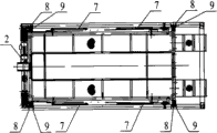
Fig. 1 is the structural front view of separate unit ascending and descending parking device.
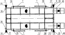
Fig. 2 is the lateral view of Fig. 1.Fig. 3 is the vertical view of Fig. 1.
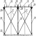
Fig. 4 is the steel frame construction front views of two ascending and descending parking devices when arranged side by side.
Fig. 5 is the lateral view of Fig. 4.Fig. 6 is the vertical view of Fig. 4.
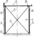
Fig. 7 is the B-B amplification view among Fig. 4.
Fig. 8 is column and the pedestal fixing situation sketch map among Fig. 4.
Fig. 9 is the structural representation of hoisting mechanism in the ascending and descending parking device.
Figure 10 is the vertical view of Fig. 9.
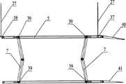
Figure 11 is the structural representation of lift platform in the ascending and descending parking device.
Figure 12 is the structure vertical view of lift platform in the ascending and descending parking device.
Figure 13 is collapsible connecting rod deployed condition sketch map.Figure 14 is the lateral view of Figure 13.
Figure 15 is collapsible connecting rod folded state sketch map.
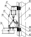
Figure 16 is that the brake block in the safety dropping prevent mechanism embeds braking bar situation sketch map.
Figure 17 deviates to brake bar situation sketch map for the brake block in the safety dropping prevent mechanism.
Figure 18 is the vertical view of Figure 16.
Figure 19 is the concrete mode of occupation sketch map of ascending and descending parking device.Figure 20 is the lateral view of Figure 19.
Figure 21 removes the vertical view behind ceiling and the power source for Figure 19.
Description of reference numerals: 1-steelframe; The 2-hoisting mechanism; The 3-battery; The 4-solar panel; The 5-boarding platform; 5a-ride crossbeam; Ride under the 6-; The collapsible connecting rod of 7-; 8-brakes bar; The 9-safety dropping prevent mechanism; The 10-column; The 11-base plate; The 12-foundation bolt; The 13-anchor slab; The 14-back rest; The 15-longeron; The 16-front-axle beam; The 17-intertie; The 18-motor mounting plate; The 19-bearing support; 20-rope sheave assembly; The 21-reducer; The 22-shaft coupling; 23-left side reel; The right reel of 24-; The 25-bearing; 26-protects the rope rod; The 27-cable wire; The 28-motor; The 29-deceleration box; 30-imports gear; The 31-idler gear; The 32-needle bearing; The 33-intermediate gear shaft; The 34-output gear; The 35-bearing; The 36-output shaft; Cable wire hook before the 37-; 38-back tightwire hook; The 39-pitman shaft; 40-upward slope guidance tape; 41-descending guidance tape; The 42-nylon slide block; The 43-brake block; The 44-spring; The 45-gag lever post; The 46-electromagnet; The 47-casing; The little axle of 48-; The 49-upper plate; The 50-lower plate; The 51-latch; The 52-rotating shaft; The 53-pedestal.
The specific embodiment
Below in conjunction with concrete accompanying drawing and embodiment the present invention is described further.
As shown in the figure: the present invention mainly is made up of pedestal 53, steelframe 1, hoisting mechanism 2, power source 3 and the up-down ride that is used to park cars.Steelframe 1 is fixedly mounted on the pedestal 53, and the hoisting mechanism 2 that power source is installed at the top of steelframe 1 and links to each other with this power source, hoisting mechanism 2 provide power through power source; Said up-down ride is connected on the cable wire 27 of hoisting mechanism 2, and the up-down ride drives through hoisting mechanism 2.
Shown in Fig. 4~6, said steelframe 1 is mainly by column 10, front-axle beam 16, longeron 15 and the back rest 14, and said column 10 adopts H shaped steel; Column 10 has four, and four root posts 10 vertically are fixed on the pedestal 53; The upper end of two adjacent upright posts 10 in rear connects fixing through the back rest 14, the upper end of two adjacent upright posts 10 in both sides connects fixing through longeron 15, and the upper end of two adjacent upright posts 10 in the place ahead connects fixing through front-axle beam 16; Said front-axle beam 16 directions are for advancing the car direction; The said back rest 14 is equipped with intertie 17 with longeron 15 directions, and this intertie 17 is used to adjust steelframe 1 verticality and parallelism, and the stability when keeping steelframe 1 load-bearing.The said back rest 14 is provided with the motor mounting plate 18 and bearing support 19 that is used to install hoisting mechanism 2; The place ahead of said longeron 15 is provided with the rope sheave assembly 20 of the cable wire 27 that is used to detour.
For guaranteeing the steadiness of column 10; Column 10 among the present invention is as shown in Figure 8 with the fixed form of pedestal 53: cast is fixed with anchor slab 13 on the said pedestal 53; Be fitted with foundation bolt 12 on the anchor slab 13, the bottom of said column 10 is provided with base plate 11, and this base plate 11 is connected fixing with foundation bolt 12.
Like Fig. 1, Fig. 2, Fig. 3, Figure 10, shown in Figure 11; Said up-down ride comprises boarding platform 5 and following ride 6; Boarding platform 5 utilizes collapsible connecting rod 7 to connect with following ride 6; The side of boarding platform 5 and following ride 6 is respectively arranged with pitman shaft 39, and the upper and lower side of collapsible connecting rod 7 is mounted on the pitman shaft 39 respectively and can freely rotates around pitman shaft 39; When following ride 6 drops to ground, collapsible connecting rod 7 auto-folders, boarding platform 5 overlap down ride 6 above.
Like Figure 13~shown in Figure 15, the symmetrical structure that said collapsible connecting rod 7 is made up of upper plate 49 and lower plate 50, upper plate 49 lower ends are connected with the employing rotating shaft 52 of lower plate 50 upper ends; Pitman shaft 39 corresponding installations in the upper plate 49 upper end perforates, this hole and boarding platform 5; Pitman shaft 39 corresponding installations in the lower plate 50 lower end perforates, this hole and following ride 6; Nearly rotating shaft 52 places of said upper plate 49 lower ends are provided with a latch 51, and said lower plate 50 upper ends are provided with arc notch, and this arc notch matches with latch 51, in order to limit the maximum bending angle of collapsible connecting rod 7.
Like Fig. 9, shown in Figure 10, said hoisting mechanism 2 mainly by reducer 21, shaft coupling 22, left reel 23, right reel 24, bearing 25, protect rope rod 26, cable wire 27 and motor 28 and form.Motor 28 is installed on the motor mounting plate 18 on the back rest 14 with reducer 21, and the power output shaft of motor 28 links to each other with reducer 21; Left side reel 23 and right reel 24 are arranged on the both sides of reducer 21, and left reel 23 is installed on the bearing support 19 on the back rest 14 through bearing 25 respectively with right reel 24; The main shaft of left side reel 23 and right reel 24 connects with output shaft 36 two ends of reducer 21 through shaft coupling 22 respectively, the cable wire 27 of reeling respectively and having two terminations on left reel 23 and the right reel 24.Cable wire hook 37 before being welded on two angles, the place ahead of said boarding platform 5, the back tightwire that has been welded on two angles, the rear of boarding platform 5 hook 38.The termination of cable wire 27 of left side reel 23 hangs the back tightwire hook 38 of ride 5 left rear corner, and rope sheave assembly 20 rear overhangs that steelframe 1 the place ahead is walked around in another termination tangle the preceding cable wire hook 37 of boarding platform 5 left-front corner.A termination of the cable wire 27 of right reel 24 hangs the back tightwire hook 38 at ride 5 right back angles, and rope sheave assembly 20 rear overhangs that steelframe 1 the place ahead is walked around in another termination tangle the preceding cable wire hook 37 at boarding platform 5 right front angles.Be respectively arranged with the rod 26 of restricting that protects that is used to protect cable wire 27 on the top of left reel 23 and right reel 24.The place ahead of said boarding platform 5 and play ride 6 is provided with upward slope guidance tape 40 and descending guidance tape 41, and descending guidance tape 41 is less than upward slope guidance tape 40, and when overlapping, descending guidance tape 41 can be inserted in the upward slope guidance tape 40 about in the of 6 for boarding platform 5 and following ride.
As shown in Figure 9, said reducer 21 can adopt matured product of the prior art.The high rotating speed of motor 28 (2000 rev/mins) is decelerated to 2.5 rev/mins via reducer 21, realized the low speed output of small-power, high pulling torque.Reducer 21 mainly is made up of deceleration box 29, input gear 30, idler gear 31, needle bearing 32, intermediate gear shaft 33, output gear 34, bearing 35 and output shaft 36; Input gear 30 is installed on the power input shaft of motor 28; Idler gear 31 is installed on the intermediate gear shaft 33 in the deceleration box 29 through needle bearing 32; Idler gear 31 is the duplicate gears that include gear wheel and pinion; Gear wheel wherein is meshed with input gear 30, and the pinion coaxial with gear wheel is meshed with output gear 34; Output gear 34 is sleeved on the output shaft 36 and utilizes flat key to connect, and output shaft 36 is installed on the deceleration box 29 through bearing 35, and deceleration box 29 is stretched out at the two ends of output shaft 36.
Like Fig. 1~shown in Figure 3, the power source among the present invention mainly is made up of solar panel 4 and battery 3, and solar panel 4 is installed in steelframe 1 top, and solar panel 4 connects into floating charge state through controller and battery 3.Because come in and go out the train number number every day of home-use car generally can be above eight times; So the battery 3 among the present invention can adopt lead-acid accumulator; It is enough to provide the required electric weight of action in theory continuous ten times; And this battery 3 connects into floating charge state with solar panel 4, and electric weight replenishes at any time, enough use.
Like Fig. 3, shown in Figure 11, in order to improve the safety in the present invention's use, four jiaos of said boarding platform 5 are separately installed with safety dropping prevent mechanism 9, and safety dropping prevent mechanism 9 has ride guiding and the omnidistance effect that prevents the ride accidental falling simultaneously.
Like Figure 16~shown in Figure 180, safety dropping prevent mechanism 9 mainly is made up of component such as braking bar 8, nylon slide block 42, brake block 43, spring 44, gag lever post 45, electromagnet 46, casing 47 and little axles 48; Braking bar 8 is fixed on the H shaped steel as column 10, and the web of braking bar 8 and H shaped steel is parallel to each other and leaves a determining deviation, evenly has a plurality of slotted holes on the length direction of braking bar 8; Said casing 47 is installed in the ride crossbeam 5a two ends of boarding platform 5, and nylon slide block 42 is installed in casing 47 outsides, and nylon slide block 42 is clasped on braking bar 8, plays the vertically-guided effect; Said brake block 43 utilizes the little axle 48 that passes the center to be installed in the casing 47, and brake block 43 can rotate around little axle 48; Match with the slotted hole of braking on the bar 8 in the lower end of brake block 43; The upper end of brake block 43 links to each other with spring 44 with electromagnet 46 simultaneously; Wherein electromagnet 46 is used to drive brake block 43 and turns clockwise and deviate to brake the slotted hole on the bar 8; Spring 44 is used to drive brake block 43 and is rotated counterclockwise and embeds the slotted hole on the braking bar 8, and gag lever post 45 is arranged on the below of brake block 43 upper ends, and gag lever post 45 is used to place restrictions on being rotated counterclockwise of brake block 43.During application, because the configuration design of brake block 43 and the effect of spring force, brake block 43 can not produce inhibition (shown in figure 16) in the ride uphill process; But when the ride accidental falling, the lower end of brake block 43 will embed in the slotted hole of braking bar 8, thereby makes whole ride put the jail on braking bar 8.In the normal down maneuver of working programme; Electromagnet 46 energisings also produce pulling force, and these electromagnet 46 pulling force overcome the pulling force of spring 44, make brake block 43 around little axle 48 rotations; The slotted hole (shown in figure 17) of bar 8 is deviate to brake in the lower end of brake block 13, thereby can descend smoothly.
The top of steelframe 1 is set up ceiling again after parts are all installed end, ceiling plays the effect of blast screen rain, and said solar panel 4 is installed on the ceiling.
Like Figure 19~shown in Figure 21, parking apparatus of the present invention is similar with common simple and easy up-down type parking equipment, promptly has only a lifting action.But its feature is to connect together upper strata sweep and lower floor's sweep with collapsible connecting rod, and can drop to ground.Therefore, when hoisting mechanism was mentioned upper strata sweep to parking stall height, lower floor's sweep also can promote simultaneously.When two layers of sweep are lifted away from 2.5 meters left and right sides, ground, do not stop like ground, the area that then steelframe takies only on the ground is 2.2 * 4 meters.And the safety dropping prevent mechanism among the present invention 9 all omnidistance accidental falling that prevents ride can or be failure to actuate in ride action the time, just there is anti-fall effect to compare in the time of can only after ride rises, being failure to actuate with current now anti-fall hook, more be of practical significance.