CN101553700A - 冷却器组件 - Google Patents
冷却器组件 Download PDFInfo
- Publication number
- CN101553700A CN101553700A CNA2007800359629A CN200780035962A CN101553700A CN 101553700 A CN101553700 A CN 101553700A CN A2007800359629 A CNA2007800359629 A CN A2007800359629A CN 200780035962 A CN200780035962 A CN 200780035962A CN 101553700 A CN101553700 A CN 101553700A
- Authority
- CN
- China
- Prior art keywords
- air
- cooling
- cooling disc
- chiller assembly
- disc
- Prior art date
- Legal status (The legal status is an assumption and is not a legal conclusion. Google has not performed a legal analysis and makes no representation as to the accuracy of the status listed.)
- Pending
Links
Images
Classifications
-
- F—MECHANICAL ENGINEERING; LIGHTING; HEATING; WEAPONS; BLASTING
- F28—HEAT EXCHANGE IN GENERAL
- F28D—HEAT-EXCHANGE APPARATUS, NOT PROVIDED FOR IN ANOTHER SUBCLASS, IN WHICH THE HEAT-EXCHANGE MEDIA DO NOT COME INTO DIRECT CONTACT
- F28D15/00—Heat-exchange apparatus with the intermediate heat-transfer medium in closed tubes passing into or through the conduit walls ; Heat-exchange apparatus employing intermediate heat-transfer medium or bodies
-
- F—MECHANICAL ENGINEERING; LIGHTING; HEATING; WEAPONS; BLASTING
- F28—HEAT EXCHANGE IN GENERAL
- F28D—HEAT-EXCHANGE APPARATUS, NOT PROVIDED FOR IN ANOTHER SUBCLASS, IN WHICH THE HEAT-EXCHANGE MEDIA DO NOT COME INTO DIRECT CONTACT
- F28D1/00—Heat-exchange apparatus having stationary conduit assemblies for one heat-exchange medium only, the media being in contact with different sides of the conduit wall, in which the other heat-exchange medium is a large body of fluid, e.g. domestic or motor car radiators
- F28D1/02—Heat-exchange apparatus having stationary conduit assemblies for one heat-exchange medium only, the media being in contact with different sides of the conduit wall, in which the other heat-exchange medium is a large body of fluid, e.g. domestic or motor car radiators with heat-exchange conduits immersed in the body of fluid
- F28D1/04—Heat-exchange apparatus having stationary conduit assemblies for one heat-exchange medium only, the media being in contact with different sides of the conduit wall, in which the other heat-exchange medium is a large body of fluid, e.g. domestic or motor car radiators with heat-exchange conduits immersed in the body of fluid with tubular conduits
- F28D1/047—Heat-exchange apparatus having stationary conduit assemblies for one heat-exchange medium only, the media being in contact with different sides of the conduit wall, in which the other heat-exchange medium is a large body of fluid, e.g. domestic or motor car radiators with heat-exchange conduits immersed in the body of fluid with tubular conduits the conduits being bent, e.g. in a serpentine or zig-zag
- F28D1/0475—Heat-exchange apparatus having stationary conduit assemblies for one heat-exchange medium only, the media being in contact with different sides of the conduit wall, in which the other heat-exchange medium is a large body of fluid, e.g. domestic or motor car radiators with heat-exchange conduits immersed in the body of fluid with tubular conduits the conduits being bent, e.g. in a serpentine or zig-zag the conduits having a single U-bend
-
- F—MECHANICAL ENGINEERING; LIGHTING; HEATING; WEAPONS; BLASTING
- F28—HEAT EXCHANGE IN GENERAL
- F28F—DETAILS OF HEAT-EXCHANGE AND HEAT-TRANSFER APPARATUS, OF GENERAL APPLICATION
- F28F1/00—Tubular elements; Assemblies of tubular elements
- F28F1/10—Tubular elements and assemblies thereof with means for increasing heat-transfer area, e.g. with fins, with projections, with recesses
- F28F1/12—Tubular elements and assemblies thereof with means for increasing heat-transfer area, e.g. with fins, with projections, with recesses the means being only outside the tubular element
- F28F1/24—Tubular elements and assemblies thereof with means for increasing heat-transfer area, e.g. with fins, with projections, with recesses the means being only outside the tubular element and extending transversely
- F28F1/32—Tubular elements and assemblies thereof with means for increasing heat-transfer area, e.g. with fins, with projections, with recesses the means being only outside the tubular element and extending transversely the means having portions engaging further tubular elements
-
- F—MECHANICAL ENGINEERING; LIGHTING; HEATING; WEAPONS; BLASTING
- F28—HEAT EXCHANGE IN GENERAL
- F28F—DETAILS OF HEAT-EXCHANGE AND HEAT-TRANSFER APPARATUS, OF GENERAL APPLICATION
- F28F2215/00—Fins
- F28F2215/04—Assemblies of fins having different features, e.g. with different fin densities
Landscapes
- Engineering & Computer Science (AREA)
- Physics & Mathematics (AREA)
- Thermal Sciences (AREA)
- Mechanical Engineering (AREA)
- General Engineering & Computer Science (AREA)
- Geometry (AREA)
- Details Of Garments (AREA)
- Treatment Of Fiber Materials (AREA)
- Magnetic Record Carriers (AREA)
Abstract
一种冷却器组件,包括多个冷却盘片(16、17),该冷却盘片排列成一阵列来限定将被冷却的气流的流经的空隙。冷却盘片(16)延伸至待冷却的空气的入口所在的一侧,而较短的冷却盘片(17)未延伸到入口所在的一侧,且所述冷却盘片交替排列布置。
Description
技术领域
本发明涉及一种冷却器组件,特别是一种安装有多个冷却盘片、用于有限空间中对气流进行冷却的冷却器组件。
背景技术
对于为了冷却空气而在气体流动通道处设置冷却盘片或者冷却薄片的冷却器组件,其气流和金属之间的热交换效率是非常重要的。盘片之间的距离的选择往往只考虑到便于制造,而通常未能达到最佳尺寸。
由于一些原因,有时安装冷却器组件的空间十分有限,所以需要小型紧凑的冷却器组件。
发明内容
本发明的主要目的是提供一种比现有技术中所述的冷却器组件更高效的冷却器组件。
在制冷效果和对流过该冷却器组件的气流降温效率方面,本设计具有实质性的提升。这可以认为是由于逐步(stepwise)缩小气隙的宽度,一定程度上增加了空气与冷却盘片的碰撞。
在权利要求2至4中具体描述了本发明的具体特征。更多细节将在下面的本发明冷却器组件的具体实施方式中具体描述。
附图说明
下面结合附图对本发明作进行进一步说明:
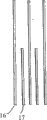
图1为本发明冷却器组件的侧面视图,其冷却管上安装有冷却盘片;
图2为图1中冷却盘片的放大视图。
具体实施方式
参照图1,一种装配有部件12、13的冷却器组件11。在部件12、13之间连接有两U型的冷却管14、15,冷却管中有制冷媒介。冷却管14和15上交替地设置有阵列排列的冷却盘片16、17。冷却盘片16延伸超过冷却器组件的总高度,并连接在冷却管14、15上;冷却盘片17延伸的长度为冷却盘片16的一半并安装在下部的冷却管14上。冷却盘片之间的间隙在上面部分为9毫米,下面部分为2.5~3毫米。与现有技术中的冷却器组件相比,在相距间隙上有了实质性的减小。这将有助于增加热交换。这样的设置使得热交换效率增加,其机理尚难于解释清楚,但可以认为是较小的间隙距离使得分子运动加剧,因此使它们之间的碰撞增加。
冷却中的空气分子在由较宽的间隙逐渐变窄的间隙中流过时可认为是有增大的特有的重力作用因此加速下落,并且同时振动得更慢,并引发附近分子的碰撞。
最小的盘片间隙距离如果小于2.5~3毫米,则会又由于结冰而发生堵塞的危险。
本实施例中冷却器组件11中在气隙(interspace)的竖直方向上,形成重力气流。根据本实施例的冷却器组件还可以使用风扇等。这将更有效的增大气流的下落速度。
根据本发明的冷却器组件11,还可以在各类技术、房间及办公场所使用。悬挂在将要冷却的产品上也是非常合适的。
当然,可以用其他不同梯度限定气流空隙的解决方案达到本发明相应的有益效果。可以在每对等全长的盘片之间设置两个或者更多如三或四种高度值不同的冷却盘片。或者可以设置多个梯度,冷却盘片之间的最小间隙应该在2.5~3毫米之间。
Claims (4)
1、一种冷却器组件,包括多个冷却盘片(16、17),所述冷却盘片成阵列排列来限定将被冷却的气流的流经的气流空隙,其特征在于:冷却盘片(16)延伸至待冷却的空气的入口所在的一侧,较短的冷却盘片(17)延伸不超过所述入口所在的一侧,所述冷却盘片交替排列布置。
2、根据权利要求1所述的一种冷却器组件,其特征在于:所述较短的冷却盘片(17)延伸至所述冷却器组件的空气流动距离的大约一半。
3、据权利要求1或2所述的一种冷却器组件,其特征在于:在所述冷却盘片(16、17)密集的一端,冷却盘片之间的距离为2.5~3毫米。
4、根据权利要求1至3中任何一项所述的一种冷却器组件,其特征在于:所述冷却器组件包括三或四种不同高度值并成阵列排列的冷却盘片,不同高度值阵列排列的冷却盘片形成具有梯度的气流空隙。
Applications Claiming Priority (2)
| Application Number | Priority Date | Filing Date | Title |
|---|---|---|---|
| NO20064338 | 2006-09-27 | ||
| NO20064338A NO329410B1 (no) | 2006-09-27 | 2006-09-27 | Anordning ved kjoleelement |
Publications (1)
| Publication Number | Publication Date |
|---|---|
| CN101553700A true CN101553700A (zh) | 2009-10-07 |
Family
ID=39230410
Family Applications (1)
| Application Number | Title | Priority Date | Filing Date |
|---|---|---|---|
| CNA2007800359629A Pending CN101553700A (zh) | 2006-09-27 | 2007-09-18 | 冷却器组件 |
Country Status (7)
| Country | Link |
|---|---|
| US (2) | US20090277621A1 (zh) |
| EP (1) | EP2069697A4 (zh) |
| JP (1) | JP2010505085A (zh) |
| CN (1) | CN101553700A (zh) |
| NO (1) | NO329410B1 (zh) |
| RU (1) | RU2473021C2 (zh) |
| WO (1) | WO2008039074A1 (zh) |
Families Citing this family (3)
| Publication number | Priority date | Publication date | Assignee | Title |
|---|---|---|---|---|
| NO336628B1 (no) * | 2012-12-07 | 2015-10-12 | Sundseth Eiendom As | Varmeveksler |
| WO2016036732A1 (en) * | 2014-09-05 | 2016-03-10 | Carrier Corporation | Frost tolerant microchannel heat exchanger for heat pump and refrigeration applications |
| WO2018029784A1 (ja) * | 2016-08-09 | 2018-02-15 | 三菱電機株式会社 | 熱交換器及びこの熱交換器を備えた冷凍サイクル装置 |
Family Cites Families (16)
| Publication number | Priority date | Publication date | Assignee | Title |
|---|---|---|---|---|
| US399493A (en) * | 1889-03-12 | I-eat-absorbing plate for cooling-coils | ||
| US2613065A (en) * | 1947-11-21 | 1952-10-07 | Chausson Usines Sa | Cooling radiator |
| US2683355A (en) * | 1951-01-24 | 1954-07-13 | Koch Butchers Supply Company | Open-top refrigerator display case |
| US3267692A (en) * | 1965-05-28 | 1966-08-23 | Westinghouse Electric Corp | Staggered finned evaporator structure |
| SU851030A1 (ru) * | 1977-05-16 | 1981-07-30 | за вители | Воздухоохладитель |
| DE2928774C2 (de) * | 1979-07-17 | 1984-03-22 | Bosch-Siemens Hausgeräte GmbH, 7000 Stuttgart | Gefrierschrank mit einem durch natürliche Konvektion gekühlten, großräumigen Gefrierraum |
| US4733293A (en) * | 1987-02-13 | 1988-03-22 | Unisys Corporation | Heat sink device assembly for encumbered IC package |
| JPH0545023A (ja) * | 1991-08-12 | 1993-02-23 | Showa Alum Corp | 熱交換器 |
| JP3126044B2 (ja) * | 1991-08-12 | 2001-01-22 | 昭和アルミニウム株式会社 | 熱交換器 |
| JPH05157478A (ja) * | 1991-12-04 | 1993-06-22 | Matsushita Refrig Co Ltd | 熱交換器とその熱交換器を備えた冷蔵庫 |
| JPH0996473A (ja) * | 1995-09-29 | 1997-04-08 | Showa Alum Corp | 熱交換器 |
| JP2001133180A (ja) * | 1999-10-29 | 2001-05-18 | Matsushita Refrig Co Ltd | フィンチューブ型熱交換器 |
| US6354367B1 (en) * | 2001-02-12 | 2002-03-12 | Rheem Manufacturing Company | Air conditioning unit having coil portion with non-uniform fin arrangement |
| US6923013B2 (en) * | 2001-05-04 | 2005-08-02 | Carrier Corporation | Evaporator for medium temperature refrigerated merchandiser |
| AU2002235029A1 (en) * | 2002-02-28 | 2003-09-09 | Lg Electronics Inc. | Heat exchanger for refrigerator |
| US7195059B2 (en) * | 2003-05-06 | 2007-03-27 | H2Gen Innovations, Inc. | Heat exchanger and method of performing chemical processes |
-
2006
- 2006-09-27 NO NO20064338A patent/NO329410B1/no unknown
-
2007
- 2007-09-18 WO PCT/NO2007/000328 patent/WO2008039074A1/en active Application Filing
- 2007-09-18 US US12/442,586 patent/US20090277621A1/en not_active Abandoned
- 2007-09-18 JP JP2009530303A patent/JP2010505085A/ja active Pending
- 2007-09-18 CN CNA2007800359629A patent/CN101553700A/zh active Pending
- 2007-09-18 RU RU2009110950/06A patent/RU2473021C2/ru active
- 2007-09-18 EP EP07834745.7A patent/EP2069697A4/en not_active Withdrawn
-
2012
- 2012-10-04 US US13/644,678 patent/US20130098581A1/en not_active Abandoned
Also Published As
| Publication number | Publication date |
|---|---|
| NO329410B1 (no) | 2010-10-18 |
| EP2069697A1 (en) | 2009-06-17 |
| WO2008039074A1 (en) | 2008-04-03 |
| NO20064338L (no) | 2008-03-28 |
| EP2069697A4 (en) | 2013-09-25 |
| RU2009110950A (ru) | 2010-11-10 |
| JP2010505085A (ja) | 2010-02-18 |
| RU2473021C2 (ru) | 2013-01-20 |
| US20130098581A1 (en) | 2013-04-25 |
| US20090277621A1 (en) | 2009-11-12 |
Similar Documents
| Publication | Publication Date | Title |
|---|---|---|
| JP4705157B2 (ja) | 複数要素からなる熱交換器 | |
| US7117928B2 (en) | Heat sinks for a cooler | |
| US20100097751A1 (en) | Air conditioning systems for computer systems and associated methods | |
| KR20080068843A (ko) | 마이크로채널 튜브를 사용하는 내오염성 응축기 | |
| US8085540B2 (en) | Tandem fan assembly with airflow-straightening heat exchanger | |
| US7540320B1 (en) | High efficiency conditioning air apparatus | |
| JP2004045014A (ja) | 熱交換器 | |
| US20070295492A1 (en) | Heat exchange system with inclined heat exchanger device | |
| WO2019153564A1 (zh) | 一种气液热交换装置 | |
| CN101171492A (zh) | 制冷装置的热交换器 | |
| CN101553700A (zh) | 冷却器组件 | |
| JP2008533424A (ja) | 熱交換器の構成 | |
| CN101120227B (zh) | 空气冷却器 | |
| US10048012B2 (en) | Tube register for indirect heat exchange | |
| US20120138284A1 (en) | Heat dissipating device | |
| JP6324732B2 (ja) | 冷却器 | |
| US6241006B1 (en) | Heat sink for CPU | |
| CN109470068A (zh) | 高效板翅式冷却器 | |
| CN101562963B (zh) | 散热装置 | |
| CN1553059A (zh) | 散热扇结构 | |
| CN101738103A (zh) | 换热装置及换热系统 | |
| JP5333048B2 (ja) | 熱交換器 | |
| CN217061437U (zh) | 一种易于散热的存储硬盘 | |
| CN217685508U (zh) | 散热器及空调室外机 | |
| CN202361603U (zh) | 一种风机盘管表冷器 |
Legal Events
| Date | Code | Title | Description |
|---|---|---|---|
| C06 | Publication | ||
| PB01 | Publication | ||
| C02 | Deemed withdrawal of patent application after publication (patent law 2001) | ||
| WD01 | Invention patent application deemed withdrawn after publication |
Open date: 20091007 |