CN100590449C - Radar apparatus - Google Patents
Radar apparatus Download PDFInfo
- Publication number
- CN100590449C CN100590449C CN200510056019A CN200510056019A CN100590449C CN 100590449 C CN100590449 C CN 100590449C CN 200510056019 A CN200510056019 A CN 200510056019A CN 200510056019 A CN200510056019 A CN 200510056019A CN 100590449 C CN100590449 C CN 100590449C
- Authority
- CN
- China
- Prior art keywords
- signal
- radar installations
- unit
- antenna
- target object
- Prior art date
- Legal status (The legal status is an assumption and is not a legal conclusion. Google has not performed a legal analysis and makes no representation as to the accuracy of the status listed.)
- Expired - Fee Related
Links
Images


Classifications
-
- B—PERFORMING OPERATIONS; TRANSPORTING
- B60—VEHICLES IN GENERAL
- B60C—VEHICLE TYRES; TYRE INFLATION; TYRE CHANGING; CONNECTING VALVES TO INFLATABLE ELASTIC BODIES IN GENERAL; DEVICES OR ARRANGEMENTS RELATED TO TYRES
- B60C19/00—Tyre parts or constructions not otherwise provided for
- B60C19/12—Puncture preventing arrangements
-
- G—PHYSICS
- G01—MEASURING; TESTING
- G01S—RADIO DIRECTION-FINDING; RADIO NAVIGATION; DETERMINING DISTANCE OR VELOCITY BY USE OF RADIO WAVES; LOCATING OR PRESENCE-DETECTING BY USE OF THE REFLECTION OR RERADIATION OF RADIO WAVES; ANALOGOUS ARRANGEMENTS USING OTHER WAVES
- G01S13/00—Systems using the reflection or reradiation of radio waves, e.g. radar systems; Analogous systems using reflection or reradiation of waves whose nature or wavelength is irrelevant or unspecified
- G01S13/02—Systems using reflection of radio waves, e.g. primary radar systems; Analogous systems
- G01S13/06—Systems determining position data of a target
- G01S13/42—Simultaneous measurement of distance and other co-ordinates
- G01S13/44—Monopulse radar, i.e. simultaneous lobing
- G01S13/4454—Monopulse radar, i.e. simultaneous lobing phase comparisons monopulse, i.e. comparing the echo signals received by an interferometric antenna arrangement
-
- G—PHYSICS
- G01—MEASURING; TESTING
- G01S—RADIO DIRECTION-FINDING; RADIO NAVIGATION; DETERMINING DISTANCE OR VELOCITY BY USE OF RADIO WAVES; LOCATING OR PRESENCE-DETECTING BY USE OF THE REFLECTION OR RERADIATION OF RADIO WAVES; ANALOGOUS ARRANGEMENTS USING OTHER WAVES
- G01S13/00—Systems using the reflection or reradiation of radio waves, e.g. radar systems; Analogous systems using reflection or reradiation of waves whose nature or wavelength is irrelevant or unspecified
- G01S13/02—Systems using reflection of radio waves, e.g. primary radar systems; Analogous systems
- G01S13/06—Systems determining position data of a target
- G01S13/08—Systems for measuring distance only
- G01S13/32—Systems for measuring distance only using transmission of continuous waves, whether amplitude-, frequency-, or phase-modulated, or unmodulated
- G01S13/34—Systems for measuring distance only using transmission of continuous waves, whether amplitude-, frequency-, or phase-modulated, or unmodulated using transmission of continuous, frequency-modulated waves while heterodyning the received signal, or a signal derived therefrom, with a locally-generated signal related to the contemporaneously transmitted signal
- G01S13/341—Systems for measuring distance only using transmission of continuous waves, whether amplitude-, frequency-, or phase-modulated, or unmodulated using transmission of continuous, frequency-modulated waves while heterodyning the received signal, or a signal derived therefrom, with a locally-generated signal related to the contemporaneously transmitted signal wherein the rate of change of the transmitted frequency is adjusted to give a beat of predetermined constant frequency, e.g. by adjusting the amplitude or frequency of the frequency-modulating signal
-
- G—PHYSICS
- G01—MEASURING; TESTING
- G01S—RADIO DIRECTION-FINDING; RADIO NAVIGATION; DETERMINING DISTANCE OR VELOCITY BY USE OF RADIO WAVES; LOCATING OR PRESENCE-DETECTING BY USE OF THE REFLECTION OR RERADIATION OF RADIO WAVES; ANALOGOUS ARRANGEMENTS USING OTHER WAVES
- G01S13/00—Systems using the reflection or reradiation of radio waves, e.g. radar systems; Analogous systems using reflection or reradiation of waves whose nature or wavelength is irrelevant or unspecified
- G01S13/02—Systems using reflection of radio waves, e.g. primary radar systems; Analogous systems
- G01S13/06—Systems determining position data of a target
- G01S13/08—Systems for measuring distance only
- G01S13/32—Systems for measuring distance only using transmission of continuous waves, whether amplitude-, frequency-, or phase-modulated, or unmodulated
- G01S13/34—Systems for measuring distance only using transmission of continuous waves, whether amplitude-, frequency-, or phase-modulated, or unmodulated using transmission of continuous, frequency-modulated waves while heterodyning the received signal, or a signal derived therefrom, with a locally-generated signal related to the contemporaneously transmitted signal
- G01S13/345—Systems for measuring distance only using transmission of continuous waves, whether amplitude-, frequency-, or phase-modulated, or unmodulated using transmission of continuous, frequency-modulated waves while heterodyning the received signal, or a signal derived therefrom, with a locally-generated signal related to the contemporaneously transmitted signal using triangular modulation
-
- G—PHYSICS
- G01—MEASURING; TESTING
- G01S—RADIO DIRECTION-FINDING; RADIO NAVIGATION; DETERMINING DISTANCE OR VELOCITY BY USE OF RADIO WAVES; LOCATING OR PRESENCE-DETECTING BY USE OF THE REFLECTION OR RERADIATION OF RADIO WAVES; ANALOGOUS ARRANGEMENTS USING OTHER WAVES
- G01S13/00—Systems using the reflection or reradiation of radio waves, e.g. radar systems; Analogous systems using reflection or reradiation of waves whose nature or wavelength is irrelevant or unspecified
- G01S13/02—Systems using reflection of radio waves, e.g. primary radar systems; Analogous systems
- G01S13/06—Systems determining position data of a target
- G01S13/42—Simultaneous measurement of distance and other co-ordinates
- G01S13/44—Monopulse radar, i.e. simultaneous lobing
- G01S13/4463—Monopulse radar, i.e. simultaneous lobing using phased arrays
-
- G—PHYSICS
- G01—MEASURING; TESTING
- G01S—RADIO DIRECTION-FINDING; RADIO NAVIGATION; DETERMINING DISTANCE OR VELOCITY BY USE OF RADIO WAVES; LOCATING OR PRESENCE-DETECTING BY USE OF THE REFLECTION OR RERADIATION OF RADIO WAVES; ANALOGOUS ARRANGEMENTS USING OTHER WAVES
- G01S7/00—Details of systems according to groups G01S13/00, G01S15/00, G01S17/00
- G01S7/02—Details of systems according to groups G01S13/00, G01S15/00, G01S17/00 of systems according to group G01S13/00
- G01S7/35—Details of non-pulse systems
- G01S7/352—Receivers
- G01S7/354—Extracting wanted echo-signals
-
- G—PHYSICS
- G01—MEASURING; TESTING
- G01S—RADIO DIRECTION-FINDING; RADIO NAVIGATION; DETERMINING DISTANCE OR VELOCITY BY USE OF RADIO WAVES; LOCATING OR PRESENCE-DETECTING BY USE OF THE REFLECTION OR RERADIATION OF RADIO WAVES; ANALOGOUS ARRANGEMENTS USING OTHER WAVES
- G01S7/00—Details of systems according to groups G01S13/00, G01S15/00, G01S17/00
- G01S7/02—Details of systems according to groups G01S13/00, G01S15/00, G01S17/00 of systems according to group G01S13/00
- G01S7/35—Details of non-pulse systems
- G01S7/352—Receivers
- G01S7/356—Receivers involving particularities of FFT processing
Abstract
A radar apparatus comprises a receiving antenna 12, consisting of a plurality of antenna elements for receiving radio waves as received signals that are emitted into space and then reflected by a target object, and a signal processor 20 that detects the distance to the target object, the speed of the target object, and azimuth thereof, based on digital signals converted from analog signals that the received signals output from the receiving antenna 12 is down-converted to a predetermined frequency band. The signal processor 20 performs monopulse processings, based on the outputs of a first processing unit for processing the outputs of parts of a plurality of the antenna elements of the receiving antenna 12 as a batch unit and a second processing unit, different from the first processing unit for processing the outputs of parts of a plurality of antenna elements of the receiving antenna 12, as another batch unit. So it can achieve a wide range of monopulse processings, even if there areconstraints with respect to mounting.
Description
Technical field
The present invention relates to a kind of radar installations, particularly a kind of digital beam that has the receiving antenna that is made of a plurality of antenna elements, forms antenna beam with digital processing forms the radar installations of (DBF:Digital BeamForming type) type.
Background technology
In recent years, the digital processing that has by a plurality of antenna element forming array antennas, usefulness signal processing part formed the radar installations of the DBF type of antenna beam, and was noticeable.
In this radar installations, each antenna element of forming array antenna is connected with RF amplifier, frequency mixer, wave filter, A/D transducer, will be by the digital signal of separately A/D transducer output, the input digit beam forms processor, carries out digital beam and forms and handle.
Wherein, the document that has discloses the quantity that limits the subsidiary expensive high-frequency analog device of each antenna element, thereby when suppressing manufacturing cost and rising, will prevent that also the maximization of locking apparatus/complicated is as the radar installations of the DBF type of purpose (for example patent documentation 1,2 etc.).
In addition, the document that also has discloses in the antenna element that constitutes planar array antenna, in the antenna element of 2 systems that the antenna element by the antenna element of odd column and even column forms, make each antenna element that constitutes these array antennas, have the monopulse radar apparatus (for example patent documentation 3 etc.) of planar array antenna of the broach ground arrangement of mutual formation pectination.In this monopulse radar apparatus, when even number of antenna elements increases, the phase center that also can make 2 antenna elements at interval below λ, thereby when improving antenna gain, also prevent to result from the increase of ambiguous (ambiguity) that phase place when phase differential detects is folding.
On the other hand, in the radar installations of the simulation process type of prior art, the example of the radar installations of many use phase place competitive list pulse modes is disclosed.Wherein, there is the emission beam that utilize to use a plurality of emitting antennas to switch the amplitude variations etc. of the received signal that produces, carries out the radar installations (for example patent documentation 4 etc.) of large-scale target detection and a plurality of Target Recognition etc.
[patent documentation 1] spy opens flat 11-160432 communique
[patent documentation 2] spy opens flat 11-064485 communique
[patent documentation 3] spy opens flat 09-162626 communique
[patent documentation 4] spy opens flat 11-281729 communique
; radar installations shown in the above-mentioned patent documentation 1,2; in order to cut down manufacturing cost; the maximization of anti-locking apparatus/complicated; and the way of the necessary inscape of the radar installations part of the DBF type by omitting prior art can be given full play to the strong point that the radar of DBF type has hardly.
In addition, in these radar installationss, be intended to limit the quantity of high frequency analog device, do not consider antenna system.As the problem of reality, the quantity of antenna element, the restriction that when actual installation, is subjected to, more than the restriction that the quantity of high frequency analog device is subjected to, for example, when there is spatial restriction in the platform that carries, will produce must the reduction antenna element problem.
In addition, radar installations shown in the above-mentioned patent documentation 3, need be with each antenna element of forming array antenna, alternately arrange in pairs or groups according to each array antenna (broach shape), from the size (being generally about λ/2) of antenna element itself and avoid on the angle of the influence of combination between antenna element, be difficult to shorten the element spacing (for example λ is following) of the antenna element of forming array antenna.Like this, in the array antenna that this radar installations possesses, promptly allow to be arranged to the phase center of 2 array antennas below the λ at interval, the antenna element of forming array antenna itself exists the antenna lobe that can not suppress to result from array antenna itself effectively and the shortcoming that produces the ambiguous scope of target azimuth at interval also more than λ.
In addition in this radar installations, an antenna element, only belong to certain array antenna, do not exist in the notion that this DBF of the output of using antenna element between different array antennas repeatedly handles, so be difficult to and form the intensive configuration of antenna element of array antenna, when there is spatial restriction in the platform that carries, just the problem of number of antenna elements appears cutting down.
And this radar installations is not almost controlled the beamwidth of each array antenna and the degree of freedom in beam orientation, so the shortcoming that the high monopulse of degree of freedom that existence is difficult to carry out the limit search district or approximately search for a plurality of fields of search is simultaneously handled.
In addition, in the radar installations shown in the above-mentioned patent documentation 4, though by switching the transmission beam that uses a plurality of transmitting antennas, realized phase place competitive list burst process, need a lot of spaces of carrying transmitting antenna but exist, when there is space constraints in the platform that carries transmitting antenna, just can not realize the problem of system.
Summary of the invention
In view of this present invention develops, even purpose is to provide when on carrying restriction being arranged, also can realize the radar installations that large-scale radar is handled.
In order to solve above-mentioned problem, achieve the goal, the radar installations that the present invention's of the present invention 1 relates to is characterized in that,
Comprise:
To send signal as the sending part of electric wave to spatial emission;
Described electric wave is arrived behind the target object electric wave by this target object reflection, the receiving antenna that constitutes by a plurality of antenna elements that receives as received signal;
To be lowered by by the received signal of described receiving antenna output be transformed into the simulating signal of fixed frequency band be transformed into the acceptance division of exporting after the digital signal;
According to the digital signal of described acceptance division output, detect the signal processing part in the orientation of described target object;
At described signal processing part, according to the part output of a plurality of antenna elements of described receiving antenna as handle unit the 1st handle unit with the part output of a plurality of antenna elements of this receiving antenna output as the 2nd different processing unit of the 1st processing unit that handles unit, carry out fixed processing.
After adopting the present invention, sending part will send signal as electric wave to spatial emission; By the receiving antenna that a plurality of antenna elements constitute, the electric wave with being reflected by this target object behind the arrival target object receives as received signal; Acceptance division will descend by the received signal of this receiving antenna output be transformed into the simulating signal of fixed frequency band export after being transformed into digital signal; Signal processing part to the digital signal of acceptance division output implement fixed processing, detect the distance that arrives target object, the speed and the orientation of target object.In addition, this signal processing part, by carry out according to the part output of a plurality of antenna elements of receiving antenna as handle unit the 1st handle unit with the part output of a plurality of antenna elements of this receiving antenna as the 1st monopulse processing of handling the output of the 2nd different processing unit of unit of handling unit, can give full play to the feature that the radar installations of DBF type has, use DBF mode realizes large-scale radar processing, also relaxes in addition in the lift-launch for antenna system to restrict.
In addition, so-called here " sending part " is the parts with transmitting antenna, oscillator, modulator etc.Equally, acceptance division is the parts with amplifier, frequency mixer, wave filter, A/D transducer etc.
In addition, the radar installations that the present invention's of the present invention 2 relates to is characterized in that: in foregoing invention, described fixed processing is that monopulse is handled.
In addition, the radar installations that the present invention's of the present invention 3 relates to is characterized in that: in foregoing invention, described monopulse is handled, and is phase place competitive list burst process.
In addition, the radar installations that the present invention's of the present invention 4 relates to is characterized in that: in foregoing invention, described monopulse is handled, and is that amplitude ratio is handled than monopulse.
In addition, the radar installations that the present invention's of the present invention 5 relates to is characterized in that: in foregoing invention, the described the 1st handles unit, will from a plurality of antenna elements of described receiving antenna extract out the antenna element output separately of fixed extraction number, as handling unit; The described the 2nd handles unit, will from constitute the described the 1st handle unit the antenna element skew the antenna element of fixed offset numbers, the antenna element output separately of extracting described fixed extraction number is as the processing unit.
In addition, the radar installations that the present invention's of the present invention 6 relates to is characterized in that: in foregoing invention, with the antenna element number of packages of described receiving antenna during as N, described fixed offset numbers is 1.
In addition, the radar installations that the present invention's of the present invention 7 relates to is characterized in that: in foregoing invention, described fixed extraction number is N-1.
In addition, the radar installations that the present invention's of the present invention 8 relates to is characterized in that: in foregoing invention, when handling unit and the described the 2nd and handle unit and handle unit as one group monopulse the described the 1st, have a plurality of these monopulses of group and handle units.
In addition, the radar installations that the present invention's of the present invention 9 relates to is characterized in that: in foregoing invention, described signal processing part will be handled the scope that detects of carrying out by described monopulse, be limited in the fixed scope.
In addition, the radar installations that the present invention's of the present invention 10 relates to is characterized in that: in foregoing invention, described signal processing part is being concluded might have a plurality of target the time, adopt in the lump fixed high resolution processing.
In addition, the radar installations that the present invention's of the present invention 11 relates to is characterized in that: in foregoing invention, as described fixed high resolution processing, adopt MUSIC (Multiple SignalClassification) method.
In addition, the radar installations that the present invention's of the present invention 12 relates to is characterized in that: in foregoing invention, described signal processing part is anticipated the described the 1st calculation process and the described the 2nd of handling unit and is handled common processing in the calculation process of unit.
In addition, the radar installations that the present invention's of the present invention 13 relates to is characterized in that: in foregoing invention, and described sending part, also have control according to described signal processing part, the modulation that variable control is intended to modulate described transmission signal with signal decide the modulation control part of parameter.
In addition, the radar installations that the present invention's of the present invention 14 relates to is characterized in that: in foregoing invention, described transmission signal is the FM-CW signal.
In addition, the radar installations that the present invention's of the present invention 15 relates to is characterized in that: in foregoing invention, described modulation control part makes modulation with the frequency offset of signal and/or variable period repeatedly.
Behind the radar installations that employing the present invention relates to, as carrying out 2 receiving antennas that radar is handled, formation by the subarray 1 that constitutes of the antenna element of fixed parts number, with by from the element group skew that constitutes subarray 1 the element of fixed offset numbers begin the subarray 2 that constitutes of the antenna element of fixed extraction number, so have the effect that the large-scale radar that can realize using the DBF mode is handled.
Description of drawings
Fig. 1 is the block scheme of structure of the 1st embodiment of the radar installations that the present invention relates to of expression.
Fig. 2 is the figure that the orientation of expression phase place competitive list pulse mode detects principle.
Fig. 3 is the synoptic diagram of characteristics of telling about the signal Processing of the 1st embodiment.
Fig. 4 be expression will receiving antenna system shown in Figure 3 the figure of equivalent constructions as by the subarray structure of each processing unit the time.
Fig. 5 is the figure of the array factor of expression 2 element arrays antennas shown in Figure 4.
Fig. 6 is the figure of basic structure of the phased-array antenna radar of expression prior art.
Fig. 7 is the notion of handling than monopulse for the amplitude ratio of using in the DBF radar installations of telling about the 2nd embodiment and the figure of drawing.
Fig. 8 is the block scheme of structure of the 3rd embodiment of the radar installations that the present invention relates to of expression.
Fig. 9-the 1st sends the figure that involves the signal waveform (relative velocity=0) that receives ripple in the expression FM-CW radar installations.
Fig. 9-the 2nd sends the figure that involves the difference frequency (relative velocity=0) that receives ripple in the expression FM-CW radar installations.
Figure 10-the 1st sends in the expression FM-CW radar installations and involves the signal waveform that the receives ripple (figure of relative velocity=v).
Figure 10-the 2nd sends in the expression FM-CW radar installations and involves the difference frequency that the receives ripple (figure of relative velocity=v).
Figure 11 is the figure of being drawn with signal to the modulation of oscillator output by modulator in order to tell about.
Embodiment
Below, with reference to the accompanying drawings, tell about the embodiment of the radar installations that the present invention relates in detail.In addition, the present invention is not subjected to the qualification of this embodiment.
(the 1st embodiment)
Fig. 1 is the block scheme of structure of the 1st embodiment of the radar installations that the present invention relates to of expression.Radar installations shown in this figure in transmitting system, comprising: transmitting antenna 11, oscillator 14, modulator 15.On the other hand, in receiving system, comprising: a plurality of receiving antennas 12 (12
1, 12
2..., 12
N); The amplifier 16 (16 that is connected with receiving antenna 12 respectively
1, 16
2..., 16
N); According to oscillator 14 signal supplied (local signal), to the descend frequency mixer 17 (17 of conversion of each signals (received signal) of these amplifiers 16 outputs
1, 17
2..., 17
N); Be connected with these frequency mixer 17 respectively, to the wave filter 18 (18 of bandwidth constraints in addition of the signal after the decline conversion
1, 18
2..., 18
N); Be connected with these wave filters 18 respectively, the signal after the bandwidth constraints carried out the A/D transducer 19 (19 of analog-to-digital conversion
1, 19
2..., 19
N); According to the digital signal of A/D transducer 19 outputs, carry out the signal processing part 20 of signal Processing.In addition, characteristics of the present invention are, the phase place competitive list burst process of carrying out in signal processing part 20.To this, will describe in detail later.
Tell about the DBF technology conception that radar installations of the present invention is suitable for here.Say straight from the shoulder, the DBF technology is the signal of the array antenna received that will constitute with a plurality of antenna elements, through after the A/D conversion, the input signal handling part is realized the technology of the control of antenna performances such as beam formation, beam scanning, secondary lobe supression with digital processes.In order to understand this DBF technology, understand the principle of the phased-array antenna radar of prior art, be its shortcut.Therefore, at first tell about the phased-array antenna radar.
Fig. 6 is the figure of basic structure of the phased-array antenna radar of expression prior art.In the figure, the normal axis for receiving antenna array of this radar (dotted line among the figure) direction is in order to interval d
0N the receiving antenna of arranging receives and during from electric wave that the direction of angle of arrival θ is injected, if with electric wave for receiving antenna 102
1Travel path length as benchmark, so for receiving antenna 102
1, 102
2..., 102
NEach travel path long just as shown in the figure, increase d respectively
0Sin θ, 2d
0Sin θ ..., (N-1) d
0Sin θ.Like this, arrive receiving antenna 102
1, 102
2..., 102
NThe phase place of electric wave, just than arriving receiving antenna 102
1This each travel path of phase lag of electric wave long.
If establishing the wavelength of electric wave is λ, phase differential so at this moment (phase lag) just is respectively (the d of 2 π/λ)
0Sin the θ, (2d of 2 π/λ)
0Sin θ ..., ((N-1) d of 2 π/λ)
0Sin θ.Phase shifter 106 (106 with the back level that is arranged on each receiving antenna
1, 106
2..., 106
N) make phase place to the direction opposite with above-mentioned phase differential in advance, just can will synthesize into equiphase from the electric wave of θ direction with each receiving antenna 102, directive property is towards the θ direction.Later signal Processing, the same with the mechanical scan radar, amplify with amplifier 107 through the received signal of phase shifter 106, with frequency mixer 108 and transmission signal mixing, conversion descends.Signal after the decline conversion is handled behind the input signal handling part 109, the information in the relevant distance/speed of final output/orientation.After adopting this phased-array antenna radar, can under the state that receiving antenna 102 is fixed, obtain the directive property of any direction by suitably controlling the amount of phase shift of phase shifter 106.
Different therewith, the ordinary construction of DBF radar is the radar installations of preamble the 1st embodiment shown in Figure 1.This radar installations is used digital signal processing, realizes the function of the phase shifter of phased-array antenna radar.
Below, use Fig. 1, tell about the action of the radar installations of this embodiment.In the figure,, generate with oscillator 14 and to send signals according to modulation signal from modulator 15, and by transmitting antenna 11 to spatial emission.On the other hand, the reflected signal from target etc. receives respectively with a plurality of receiving antennas 12.These received signals are amplified respectively with amplifier 16, to frequency mixer 17 outputs.In frequency mixer 17, according to the conversion that descends of the received signal of oscillator 14 signal supplied (local signal) pair amplifier 16 output.In wave filter 18, decline figure signal of giving each frequency mixer 17 output is bandwidth constraints in addition, be transformed into digital signal with A/D transducer 19 by simulating signal again after, export to signal processing part 20.
In signal processing part 20, owing to can freely change phase place and amplitude, so use fixed rule adjust that to carry out signal behind the amplitude, phase place of the digital signal that the receiving antenna of each element receives synthetic, thereby can form the direction or the antenna directivity of shape arbitrarily arbitrarily.This antenna directivity that will carry out in signal processing part is synthetic to be handled, and is called " digital beam forms (DBF) ".
The big characteristics of DBF, in case be after the signal that whole receiving antennas receive is imported as digital signal, just can be according to the beam of the synthetic any direction of this digital signal.In other words, import signal after, just can form a plurality of beams.In the present invention, these characteristics have also been maximally utilised.
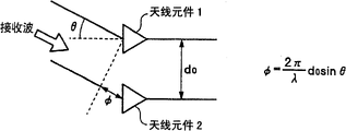
Fig. 2 is the figure that the orientation of expression phase place competitive list pulse mode detects principle.In the figure, when receiving angle that ripple constitutes θ with the normal direction with antenna surface and injecting receiving antenna 1 and receiving antenna 2, between the received signal of the received signal of receiving antenna 1 and receiving antenna 2, produce φ=(d of 2 π/λ)
0The phase differential of Sin θ.Like this, in phase place competitive list pulse mode, detect this phase difference after, just can be according to θ=Sin
-1(φ λ/2 π d
0) formula, detect the angle of arrival θ of electric wave.
Fig. 3 is a synoptic diagram of telling about the characteristics of the 1st embodiment signal Processing.In the figure, the signal processing part 20 that is connected with the equally spaced linear array of a plurality of receiving antennas 12 formations is shown.In addition, to amplifier 16, frequency mixer 17, wave filter 18, the A/D transducer 19 that is connected with receiving antenna 12 respectively, all not shown.
In Fig. 3, signal processing part 20 carries out according to the signal Processing that are compiled to 2 processing units that handle unit 1 and processing unit 2.In handling unit 1, synthetic processing 12
1~12
N-1The output of receiving antenna of N-1 element.On the other hand, in handling unit 2, to the group of the receiving antenna that becomes the object of handling unit 1, synthetic processing downwards one by one 12 of skew
2~12
NThe output of receiving antenna of one 1 elements of N.Like this, handle unit 1 usefulness 12
1~12
N-1The receiving antenna array (subarray 1) of N-1 element constitute, handle unit 2 usefulness 12
2~12
NThe receiving antenna array (subarray 2) of N-1 element constitute.In addition, these are handled unit 1 and handle unit 2, and receiving antenna 1 and the receiving antenna 2 with Fig. 2 is corresponding respectively.
Fig. 4 be expression will receiving antenna system shown in Figure 3 the figure of equivalent constructions as by the subarray structure of each processing unit the time.Only be offset the subarray structure of 1 element to below shown in Figure 3, if subarray is considered as antenna element, so just as shown in Figure 4, with the array antenna structure equivalence of general's element separately as 2 elements of subarray, in addition, the interval of (subarray 1 and subarray 2) between these subarrays is with the element spacing d of each antenna element
0(minimum interval) equates.
In addition, the interval between subarray 1 and the subarray 2 is compared with wavelength, when setting too greatly, on the phase differential between subarray 1 and the subarray 2, just produced and obscure, leading around phase place, be difficult to detect correct phase differential.This problem with subarray is identical as the problem of the beam lobe of 2 element arrays antennas of 1 element, can be replaced as and do not make this beam lobe generation zero-bit.
Fig. 5 is the figure of the array factor of expression 2 element arrays antennas shown in Figure 4.As shown in the drawing, for angle of arrival θ, element spacing is near near 0.5 λ (λ: in the time of wavelength), become the beam lobe that gently reduces, and when element spacing is 2 λ, 15 degree and 50 degree, produce bigger zero-bit (null).Because along with element spacing becomes big, this zero-bit moves to normal direction (0 degree direction), so element spacing is set smallerly as much as possible, is very important.
,, want to realize above-mentioned subarray structure, just must increase the quantity of receiving antenna itself, also have the antenna that will increase configuration with antenna system as prior art, overlapping with the part of existing antenna, the problem that can not dispose effectively., the radar installations of present embodiment is to make the structure of antenna system constant, utilizes the function of signal processing part to realize this subarray structure.In other words, the signal that will receive with receiving antenna behind digital signal input signal handling part, by using a part of digital signal repeatedly, is realized the structure with above-mentioned subarray structural equivalents.Utilize this subarray structure, it is long to increase substantial reception opening, increases receiving gain.In addition, can also improve and find out performance.
In addition,, receive beam, needn't adopt the structure of switching a plurality of transmitting antennas, can properly settle the problem of mounting space as prior art so can form many simultaneously owing to can use the received signal of input earlier simultaneously repeatedly.
And, in the radar installations of present embodiment, constitute the received signal of the antenna element of subarray 1, received signal with the antenna element that constitutes subarray 2, by shared, and used repeatedly, so obtain the identical operation part in advance, recycle its operation result, just can improve the treatment effeciency of signal processing part.
Generally, in the monopulse angle measurement, when having a plurality of target in same the beam, receiving ripple becomes composite wave from the reflection wave of a plurality of targets, is difficult to separate these targets for a plurality of targets, detects its correct direction respectively., in the radar installations of present embodiment,, so as previously mentioned, after the input received signal, can carry out appropriate signals and handle, earlier so can also address this problem owing in the radar installations of DBF type, adopt phase place competitive list burst process.In other words, concluding to have a plurality of target the time,, just can address the above problem as long as adopt high-resolution such as MUSIC (Multiple SignalClassification) method to handle simultaneously.
In addition, usually, it is many that high-resolution such as MUSIC method can be handled computational throughput, is difficult to export rapidly result.; in the radar installations of present embodiment; it is not the processing of often carrying out according to the MUSIC method; and can be only concluding when needing high-resolution to handle; just use this processing, in addition, sensing range also be limited in the fixed scope; so computational throughput is also cut down, can carry out a plurality of targets effectively with on the processing time, being out of question and detect.
In sum, as 2 receiving antennas that carry out phase place competitive list burst process, formation by the subarray 1 that forms of the antenna element of fixed parts number, with from the element group skew that constitutes subarray 1 the element of fixed offset numbers initial the subarray 2 that forms of the antenna element of fixed extraction number, so can realize using the large-scale phase place competitive list burst process of DBF mode.
In addition, in the radar installations of present embodiment,, the situation of carrying out phase place competitive list burst process, constituting 2 subarrays shown in Figure 4 is told about, but be not limited to this structure as subarray 1 and subarray 2.For example, can also be with antenna element every an alternate combinations.
In addition, 2 subarrays that carry out phase place competitive list burst process can also be done just a plurality of.That is: can constitute the subarray that carries out phase place competitive list burst process more than 2.For example: utilize this a plurality of 2 subarrays, can carry out the different a plurality of phase place competitive list burst process of sensing range, can also separate, discern a plurality of targets according to the result of a plurality of phase place competitive list burst process.
In addition, the treatment technology that present embodiment is told about does not rely on the key element of the kind of radar installations, can use on various radar installationss such as pulse Doppler radar device and FM-CW radar installations.
(the 2nd embodiment)
Fig. 7 is the notion of handling than monopulse for the amplitude ratio of using in the DBF radar installations of telling about the 2nd embodiment and the figure of drawing.In addition, the structure of the radar installations of the 2nd embodiment is identical with the structure of the radar installations of the 1st embodiment shown in Figure 1.In the signal processing part 20 of the radar installations of Fig. 1, as shown in Figure 7, can form the reception beam 32 that makes subarray 1 and the reception beam 33 partly overlapping beams of subarray 2 at an easy rate.After forming this beam, usually as long as the step of handling than monopulse according to the amplitude ratio of being known by people detects processing.
In addition, also the same in the radar installations of present embodiment with the 1st embodiment, can take various subarray structures and various processing form, they can both obtain the effect identical with the 1st embodiment respectively.
(the 3rd embodiment)
Fig. 8 is the block scheme of structure of the 3rd embodiment of the radar installations that the present invention relates to of expression.Radar installations shown in this figure in the structure of the 1st embodiment shown in Figure 1, between modulator 15 and signal processing part 20, has modulation control part 22.In addition, other structure is identical with the 1st embodiment or equal, for these parts, gives identical symbol.
In radar installations, when there is the target etc. of fixture and medium and long distance in the direction of target object, when perhaps there is strong noise source etc. in the direction beyond the target object, if remove these signals, just toward the signal beyond back flase drop goes out to detect object without wave filter 18.Therefore, in the radar installations of present embodiment, modulation control part 22 carries out variable control to the modulation of modulator 15 outputs with the various parameters of signal according to the control of signal processing part 20.Here, what is called " the modulation various parameters of signal " is for example if the FM-CW radar installations is exactly that modulation uses the frequency offset of signal to reach repeatedly the cycle etc.; If the pulse Doppler radar device, then be modulation with the pulse of signal cycle and pulse width etc. repeatedly.
Below, be example with the FM-CW radar installations, tell about the action of the radar installations of the 3rd embodiment.When telling about, at first tell about the principle of FM-CW radar installations.
In the FM-CW radar installations, utilize the triangular wave etc. of for example hundreds of Hz that oscillator produces to send the FM modulating wave of FM modulation, receive reflected signal from target object after, the FM modulating wave as local signal, is carried out the FM detection to received signal.From the reflection wave of target object, according to the distance between radar and the target object, the Doppler shift that causes according to relative velocity also, with send signal produce skew (beat, beat).Like this, can be according to the skew of frequency, instrumentation arrives distance and the relative velocity with target object.In the FM-CW radar installations, use signal as modulation, use triangular wave mostly, below to telling about with the situation of signal use triangular wave as modulation.But except triangular wave, can also use triangular waves such as sawtooth wave, trapezoidal wave modulation signal in addition.
Fig. 9 is the figure that the principle of the FM-CW radar installations when telling about relative velocity with target object for " 0 " is drawn.Fig. 9-the 1st, expression sends the figure that involves the signal waveform that receives ripple, Fig. 9-the 2nd, expression sends the figure that involves the difference frequency that receives ripple.In Fig. 9-1, the waveform that sends ripple is a triangular wave, and frequency changes shown in solid line.In addition, the dispatching centre frequency of transmission ripple is f
0, the FM modulation width is Δ f, toggle frequency is f
mThis sends ripple and is received with antenna by target object reflection back, becomes the reception ripple shown in this figure dotted line.The distance that is set to target object is that the velocity of propagation of R, electric current is C, and T two-way time of the electric wave between the target object is T=2R/C.This receives ripple, according to the distance between radar and target object, produces the skew (beat) with the frequency that sends signal.At this moment, this difference frequency ingredient f
b, can be represented by the formula:
f
b=f
r=(4·Δf·f
m/C)R …(1)
On the other hand, Figure 10 is the figure that the principle of the FM-CW radar installations when telling about relative velocity with target object for " v " is drawn.Figure 10-the 1st, expression sends the figure that involves the signal waveform that receives ripple, Figure 10-the 2nd, expression sends the figure that involves the difference frequency that receives ripple.In Figure 10-1, send wave frequency and shown in solid line, change.This sends ripple and is received with antenna by target object reflection back, becomes the reception ripple shown in this figure dotted line.This receives ripple, according to the distance between radar and target object, produces the skew (beat) with the frequency that sends signal.At this moment, be v because relative velocity is arranged between radar and target object, so in frequency content, produce Doppler shift, the difference frequency ingredient f
b, change according to following formula:
f
b=f
r±f
d=(4·Δf·f
m/C)R+(2·f
o/C)v …(2)
In formula (1), formula (2), the meaning of each symbol is as follows:
f
b: shipper receiver difference beat frequency, f
r: frequency of distance, f
d: speed in frequency, f
o: send the centre frequency of ripple, Δ f: frequency offset, f
m: the toggle frequency of modulating wave, C: the light velocity (speed of electric wave), T: electric wave is to the two-way time of target object, R: to the distance of target object, v: with the relative velocity of target object.
In addition, in signal processing part 20, the Beat Signal to shown in the formula (2) carries out signal Processing such as FFD conversion, obtains distance and relative velocity etc.
Below, tell about control, to the situation of carrying out variable control with signal to the modulation of oscillator 14 outputs by modulator 15 with modulation control part 22 shown in Figure 8.Figure 11 is in order to tell about the figure that this modulation is drawn with signal.
At first, tell about the situation of variable control modulation with the frequency offset Δ f of signal.As described in the telling about of Fig. 9-1 and Fig. 9-2, with the relative velocity of target object be 0 o'clock, the reception ripple that target object reflection back is accepted with antenna according to the distance between radar and target object, produces and the frequency shift (FS) (beat) that sends signal.This difference frequency ingredient f
b, can represent with the formula (1) that preamble is told about.List formula (1) once more here:
f
b=f
r=(4·Δf·f
m/C)R …(1)
In formula (1), if be directed to Δ f, the frequency offset of its expression FM modulation.Figure 11 (b) is that expression is used signal as modulation, in the time of will having the common frequency offset triangular wave of (being equivalent to Δ f) (Figure 11 (a)) for benchmark, and the figure of the triangular wave when making this frequency offset become 2 times.
In radar installations shown in Figure 8, by modulation control part 22 control modulators 15, when making modulation become to n times, by formula (1) as can be known: the difference frequency ingredient f with the frequency offset Δ f of signal
bValue become n doubly.In received signal, the signal f from target object appears
bWith the clutter composition.So, from the frequency f of the signal of target object
b,, become n doubly according to the variation of Δ f.On the other hand, because the frequency content of clutter composition is constant, so can discern signal and clutter composition from target object.In addition, these discern processing, carry out with signal processing part 20.
Then, tell about the situation of variable control modulation with the modulation period of signal.Figure 11 (c) is that expression is used signal as modulation, and the triangular wave of frequency offset (being equivalent to Δ f) that will have Figure 11 (a) is during as benchmark, the figure of the triangular wave when making this cycle becoming n times repeatedly.By formula (1) as can be known: make the repeatedly period T of modulation with signal
mAfter becoming n times, the difference frequency ingredient f
bJust become 1/n.
In radar installations shown in Figure 8, by modulation control part 22 control modulators 15, when making modulation become to n times with cycle repeatedly of signal, the difference frequency ingredient f
bValue just become 1/n.Like this, by modulation control part 22 control modulators 15, make the period T repeatedly of triangular wave
mBecome n doubly after, from the frequency f of the signal of target object
b, just according to T
mVariation, become 1/n doubly.On the other hand, the frequency content of clutter composition is changed, so can discern signal and clutter composition from target object.In addition, these discern processing, also carry out with signal processing part 20.
In addition, and target object between the difference frequency ingredient f of relative velocity when being v
b, also can represent with the formula (2) that preamble is told about.Formula (2) is also listed once more:
f
b=f
r±f
d=(4·Δf·f
m/C)R+(2·f
o/C)v …(2)
And when the relative velocity between the target object is v, also as can be known: reach period T repeatedly by controlled frequency offset f by formula (2)
m, can discern signal and clutter composition from target object.In addition, undoubtedly, controlled frequency offset f or period T repeatedly
m, the slope of modulating with signal with control is equivalent.
In addition, above-mentioned control and treatment, the same with the 1st, the 2nd embodiment, do not need often to carry out.For example, can detect to have a plurality of target in the object range time concluding, use this control and treatment.Carry out this control and treatment, owing to detect scope and limited, the load of computing is also alleviated,, carry out detecting of a plurality of targets effectively so can shorten the processing time.
In sum, behind the radar installations of employing present embodiment,,, be target object and other signal thereby discern by the composition that identification changes according to these variations by making for example frequency offset and/or the cycle variation repeatedly of slope of modulating with signal.
In addition, in the radar installations of present embodiment, be example with the FM-CW radar installations, having told about in order to discern is the processing that above-mentioned target object carries out with other signal.But, for example also go for pulse Doppler radar device etc.At this moment, as long as the pulse repetition frequency of control modulation usefulness signal and pulse width etc.
Generally speaking, the radar installations that the present invention relates to, the radar installations as the distance that detects mobile object, speed, method is of great use, and is specially adapted to carry when antenna system is the platform etc. of free intersexuality restriction.
Claims (13)
1, a kind of radar installations is characterized in that,
Comprise:
To send signal as the sending part of electric wave to spatial emission;
Described electric wave is arrived behind the target object electric wave by this target object reflection, the receiving antenna that constitutes by many antenna elements of N that receives as received signal;
To be descended by the received signal of described receiving antenna output transforms to lower frequency band, and is transformed into the acceptance division of exporting after the digital signal; And
According to the digital signal of described acceptance division output, detect the signal processing part in the orientation of described target object,
In described signal processing part, handle unit and the 2nd phase differential of handling between the unit according to the 1st, carry out phase place competitive list burst process, the described the 1st handle unit with the output of a part in many antenna elements of N of described receiving antenna as handling unit, and described the 2nd processing unit is different from the described 1st processing unit of output a part of in many antenna elements of N of described receiving antenna as the processing unit, and the described the 1st part of handling the antenna element that comprises in the unit also is contained in described the 2nd processing unit.
2, radar installations as claimed in claim 1 is characterized in that: the described the 1st handles unit, and the antenna element output separately that will extract the extraction number of regulation out from many antenna elements of N of described receiving antenna is as handling unit;
The described the 2nd handles unit, will be from constituting the antenna element that the described the 1st antenna element of handling unit is offset the offset numbers of regulation, and the antenna element output separately of extracting the extraction number of described regulation out is as handling unit.
3, radar installations as claimed in claim 2 is characterized in that: the offset numbers of described regulation is 1.
4, radar installations as claimed in claim 3 is characterized in that: the extraction number of described regulation is N-1.
5, as each described radar installations of claim 1~3, it is characterized in that: when handling unit and the described the 2nd and handle unit and handle unit as one group monopulse the described the 1st, described one group monopulse is handled unit and is had a plurality of.
6, as each described radar installations of claim 1~4, it is characterized in that: described signal processing part, will handle the scope that detects of carrying out by described monopulse, limit within the limits prescribed.
7, as each described radar installations of claim 1~4, it is characterized in that: described signal processing part, concluding might have a plurality of target the time, described digital signal is adopted in the lump the high resolution processing of regulation.
8, radar installations as claimed in claim 7 is characterized in that: as the high resolution processing of described regulation, adopt the MUSIC method.
9, as each described radar installations of claim 2~4, it is characterized in that: described signal processing part, anticipate the described the 1st calculation process and the described the 2nd of handling unit and handle common processing in the calculation process of unit.
10, as each described radar installations of claim 1~4, it is characterized in that: described sending part, also have the modulation control part, this modulation control part is according to the control of described signal processing part, makes the modulation that is intended to modulate described transmission signal variable with signal.
11, radar installations as claimed in claim 1 is characterized in that: described transmission signal is the FM-CW signal.
12, radar installations as claimed in claim 10 is characterized in that: described transmission signal is the FM-CW signal.
13, radar installations as claimed in claim 10 is characterized in that: described modulation control part makes described modulation with the frequency offset of signal and/or variable period repeatedly.
Applications Claiming Priority (2)
| Application Number | Priority Date | Filing Date | Title |
|---|---|---|---|
| JP2004082627 | 2004-03-22 | ||
| JP2004082627A JP4447946B2 (en) | 2004-03-22 | 2004-03-22 | Radar equipment |
Publications (2)
| Publication Number | Publication Date |
|---|---|
| CN1673770A CN1673770A (en) | 2005-09-28 |
| CN100590449C true CN100590449C (en) | 2010-02-17 |
Family
ID=34858372
Family Applications (1)
| Application Number | Title | Priority Date | Filing Date |
|---|---|---|---|
| CN200510056019A Expired - Fee Related CN100590449C (en) | 2004-03-22 | 2005-03-22 | Radar apparatus |
Country Status (5)
| Country | Link |
|---|---|
| US (1) | US7190305B2 (en) |
| EP (1) | EP1580572A1 (en) |
| JP (1) | JP4447946B2 (en) |
| KR (1) | KR100749560B1 (en) |
| CN (1) | CN100590449C (en) |
Families Citing this family (51)
| Publication number | Priority date | Publication date | Assignee | Title |
|---|---|---|---|---|
| JP4447946B2 (en) * | 2004-03-22 | 2010-04-07 | 富士通テン株式会社 | Radar equipment |
| DE102004059915A1 (en) * | 2004-12-13 | 2006-06-14 | Robert Bosch Gmbh | radar system |
| JP4098318B2 (en) * | 2005-03-29 | 2008-06-11 | 本田技研工業株式会社 | Electronic scanning millimeter wave radar apparatus and computer program |
| JP4902985B2 (en) * | 2005-11-15 | 2012-03-21 | 富士通テン株式会社 | Monopulse radar apparatus calibration method and calibration determination apparatus |
| DE102005060875A1 (en) * | 2005-12-20 | 2007-06-21 | Robert Bosch Gmbh | Method and device for signal processing at an angle determination by means of microwave motion sensors |
| DE102006054721A1 (en) * | 2006-03-31 | 2007-11-29 | Volkswagen Ag | Device and method for detecting one or more objects in the vicinity of a vehicle |
| KR100750967B1 (en) * | 2006-05-02 | 2007-08-22 | 한국전기연구원 | High resolution short range radar system using virtual array antenna system |
| DE102007038513A1 (en) * | 2007-08-16 | 2009-02-19 | Robert Bosch Gmbh | Monostatic multibeam radar sensor for motor vehicles |
| JP4656124B2 (en) * | 2007-11-09 | 2011-03-23 | 株式会社デンソー | Direction detection device |
| CN101482609B (en) * | 2008-03-05 | 2013-11-20 | 中国科学院嘉兴无线传感网工程中心 | Extreme low-altitude low-speed flat micro-strip radar detector based on wireless sensing network |
| JP4715871B2 (en) * | 2008-06-10 | 2011-07-06 | 株式会社デンソー | Direction detection device, radar device |
| EP2189809A1 (en) | 2008-11-24 | 2010-05-26 | Mitsubishi Electric R&D Centre Europe B.V. | Object ranging |
| KR100924326B1 (en) * | 2009-02-23 | 2009-11-02 | 삼성탈레스 주식회사 | Ultra wide band radar apparatus for foliage penetration and signal processing method |
| JP4996640B2 (en) * | 2009-03-10 | 2012-08-08 | 株式会社東芝 | Antenna device, radar device |
| US9392521B2 (en) * | 2009-03-18 | 2016-07-12 | Telecommunication Systems, Inc. | System and method for concurrently determining locations of mobile device in wireless communication network |
| JP5726852B2 (en) * | 2009-04-06 | 2015-06-03 | コンティ テミック マイクロエレクトロニック ゲゼルシャフト ミットベシュレンクテル ハフツングConti Temic microelectronic GmbH | Radar system and method having apparatus for separating transmitted signal and received signal and suppressing jamming radiation |
| JP5345029B2 (en) * | 2009-09-10 | 2013-11-20 | 富士通テン株式会社 | Radar equipment |
| DE102009045141A1 (en) | 2009-09-30 | 2011-03-31 | Robert Bosch Gmbh | Radar sensor with IQ receiver |
| CN101980048B (en) * | 2010-09-29 | 2012-09-19 | 中国科学院国家天文台 | Antenna array forming technology-based ground-based radar system for space debris |
| US8384588B2 (en) | 2010-10-26 | 2013-02-26 | Raytheon Company | Beam stabilization for wideband phase comparison monopulse angle estimation with electronically steered antennas |
| US8451173B2 (en) | 2011-04-21 | 2013-05-28 | Raytheon Company | Maximum likelihood angle estimation of wideband signals using phased array antennas |
| JP2013024836A (en) * | 2011-07-26 | 2013-02-04 | Japan Radio Co Ltd | Radar receiver |
| FR2978560A1 (en) * | 2011-07-29 | 2013-02-01 | Jean-Marc Cortambert | DEVICE FOR DETECTION OF SCRATCH-RESISTANT TARGET, DETECTION METHOD |
| US9316731B2 (en) * | 2011-08-04 | 2016-04-19 | Lattice Semiconductor Corporation | Low-cost tracking system |
| CN103562744B (en) * | 2011-08-12 | 2016-09-28 | 松下电器产业株式会社 | Radar installations |
| JP5873509B2 (en) * | 2012-02-09 | 2016-03-01 | アルプス電気株式会社 | Antenna apparatus and arrival angle calculation apparatus using the same |
| DE102012016475B4 (en) * | 2012-08-17 | 2022-09-08 | Hensoldt Sensors Gmbh | Direction finding method based on the monopulse principle |
| US9365126B2 (en) * | 2013-05-10 | 2016-06-14 | Qualcomm Incorporated | System and method for detecting the presence of a moving object below a vehicle |
| KR20140144826A (en) * | 2013-06-12 | 2014-12-22 | 주식회사 만도 | Radar apparatus and antenna apparatus |
| KR20150015067A (en) * | 2013-07-31 | 2015-02-10 | 주식회사 만도 | Radar calibration system in vehicle |
| JP6260004B2 (en) * | 2013-08-29 | 2018-01-17 | パナソニックIpマネジメント株式会社 | Radar system and target detection method |
| US9229100B2 (en) * | 2013-09-20 | 2016-01-05 | Toyota Motor Engineering & Manufacturing North America, Inc. | Phased array radar with monopulse algorithm measurement |
| DE102013113806A1 (en) * | 2013-12-11 | 2015-06-11 | Hella Kgaa Hueck & Co. | Radar device and method therefor |
| CN104076335A (en) * | 2014-06-16 | 2014-10-01 | 西安天和防务技术股份有限公司 | Rader receiving system |
| KR102216774B1 (en) * | 2014-06-23 | 2021-02-17 | 현대모비스 주식회사 | Apparatus and method for processing radar signal of vehicle |
| US9784820B2 (en) * | 2014-09-19 | 2017-10-10 | Delphi Technologies, Inc. | Radar system with phase based multi-target detection |
| US9470777B2 (en) * | 2014-09-19 | 2016-10-18 | Delphi Technologies, Inc. | Radar system for automated vehicle with phase change based target catagorization |
| US10324166B2 (en) * | 2015-09-28 | 2019-06-18 | Rockwell Collins, Inc. | Affordable combined pulsed/FMCW radar AESA |
| KR102438228B1 (en) * | 2015-10-07 | 2022-08-31 | 주식회사 에이치엘클레무브 | Radar apparatus for vehicle and method for estimating angle of target using the same |
| JP6365494B2 (en) * | 2015-10-07 | 2018-08-01 | 株式会社デンソー | Antenna device and target detection device |
| JP6400556B2 (en) * | 2015-10-08 | 2018-10-03 | 株式会社ヨコオ | Radar equipment |
| TWI598611B (en) | 2015-11-25 | 2017-09-11 | 啟碁科技股份有限公司 | Radar Antenna System |
| CN106814348B (en) * | 2015-12-01 | 2019-11-01 | 启碁科技股份有限公司 | Radar antenna system |
| KR101644066B1 (en) * | 2015-12-15 | 2016-07-29 | 주식회사 바이다 | multi-beam generation radar apparatus |
| US20170328994A1 (en) * | 2016-05-16 | 2017-11-16 | Nidec Elesys Corporation | Radar system |
| US10914829B2 (en) * | 2017-01-27 | 2021-02-09 | Panasonic Intellectual Property Management Co., Ltd. | Positioning sensor, sensor, and method |
| EP3521852B1 (en) * | 2018-01-31 | 2021-07-14 | Sivers Wireless AB | Radar beamforming method |
| WO2019224950A1 (en) * | 2018-05-23 | 2019-11-28 | 三菱電機株式会社 | Radar device |
| EP3948341A4 (en) * | 2019-04-03 | 2022-11-30 | Saab Ab | Antenna array and a phased array system with such antenna array |
| CN110058226B (en) * | 2019-04-17 | 2021-05-07 | 北京遥感设备研究所 | Phased array radar angle measurement system based on positive and negative frequency modulation slope linear frequency modulation |
| KR102098862B1 (en) * | 2019-08-22 | 2020-05-15 | 국방과학연구소 | Apparatus and method for estimating direction of arrival in a hybird beamforming system |
Family Cites Families (37)
| Publication number | Priority date | Publication date | Assignee | Title |
|---|---|---|---|---|
| US4646093A (en) * | 1984-08-22 | 1987-02-24 | Raytheon Company | Digital monopulse for tracking radar |
| US5600326A (en) * | 1991-12-16 | 1997-02-04 | Martin Marietta Corp. | Adaptive digital beamforming architecture and algorithm for nulling mainlobe and multiple sidelobe radar jammers while preserving monopulse ratio angle estimation accuracy |
| US5315304A (en) | 1993-07-02 | 1994-05-24 | The United States Of America As Represented By The Secretary Of The Navy | Digital monopulse |
| US5633642A (en) * | 1993-11-23 | 1997-05-27 | Siemens Aktiengesellschaft | Radar method and device for carrying out the method |
| JP3663703B2 (en) | 1995-12-05 | 2005-06-22 | 株式会社デンソー | Monopulse radar device |
| DE69829946T2 (en) | 1997-01-21 | 2006-05-04 | Automotive Systems Laboratory Inc., Farmington Hills | PRÄDIKATIVES COLLISION DISCOVERY SYSTEM |
| JPH10253730A (en) * | 1997-03-06 | 1998-09-25 | Fujitsu Ltd | Wide-band direction estimation device and method |
| US5986605A (en) * | 1997-05-23 | 1999-11-16 | Raytheon Company | Method for improving monopulse processing of aperture segment outputs |
| JP3597678B2 (en) | 1997-08-18 | 2004-12-08 | 富士通株式会社 | Radar equipment |
| JPH11125672A (en) | 1997-10-24 | 1999-05-11 | Mitsubishi Electric Corp | Fm-cw radar |
| JP3525426B2 (en) | 1997-11-28 | 2004-05-10 | トヨタ自動車株式会社 | Radar equipment |
| DE19754720C2 (en) | 1997-12-10 | 2000-12-07 | Adc Automotive Dist Control | Method for operating a radar system |
| JP4238375B2 (en) * | 1997-12-25 | 2009-03-18 | 株式会社豊田中央研究所 | Radar equipment |
| JPH11281729A (en) | 1998-03-31 | 1999-10-15 | Toyota Central Res & Dev Lab Inc | Beam switched radar apparatus |
| JP2000031736A (en) | 1998-07-07 | 2000-01-28 | Toyota Central Res & Dev Lab Inc | Phase mono-pulse antenna system |
| JP3518363B2 (en) * | 1998-09-07 | 2004-04-12 | 株式会社デンソー | FMCW radar device, recording medium, and vehicle control device |
| DE19942665B4 (en) | 1998-09-07 | 2014-02-13 | Denso Corporation | FM CW radar apparatus for measuring the distance to a target and the relative velocity of the target |
| KR100318842B1 (en) | 1998-11-26 | 2002-04-22 | 윤종용 | Frequency Detection Method in Digital Phase Control Loop |
| JP2000221260A (en) | 1999-02-03 | 2000-08-11 | Mitsubishi Electric Corp | Image radar device |
| JP3622565B2 (en) | 1999-03-31 | 2005-02-23 | 株式会社デンソー | Radar equipment |
| JP3498624B2 (en) | 1999-03-31 | 2004-02-16 | 株式会社デンソー | Radar equipment |
| JP4258941B2 (en) | 1999-06-03 | 2009-04-30 | 株式会社デンソー | Radar equipment |
| US6573859B2 (en) * | 2000-02-07 | 2003-06-03 | Toyota Jidosha Kabushiki Kaisha | Radar apparatus |
| JP3463747B2 (en) | 2000-02-14 | 2003-11-05 | トヨタ自動車株式会社 | FM-CW radar device |
| JP2001264427A (en) | 2000-03-22 | 2001-09-26 | Toshiba Corp | Radar |
| JP4111667B2 (en) * | 2000-09-26 | 2008-07-02 | 富士通テン株式会社 | FM-CW radar equipment |
| US6697009B2 (en) * | 2001-06-15 | 2004-02-24 | Lockheed Martin Corporation | Adaptive digital beamforming architecture for target detection and angle estimation in multiple mainlobe and sidelobe jamming |
| JP3829659B2 (en) | 2001-07-02 | 2006-10-04 | 三菱電機株式会社 | Radar equipment |
| JP3821688B2 (en) * | 2001-10-30 | 2006-09-13 | 三菱電機株式会社 | Radar equipment |
| JP3918573B2 (en) | 2002-02-08 | 2007-05-23 | 三菱電機株式会社 | Radar equipment |
| JP3610052B2 (en) * | 2002-04-18 | 2005-01-12 | 三菱電機株式会社 | Radar equipment |
| JP4190335B2 (en) * | 2003-04-03 | 2008-12-03 | 富士通テン株式会社 | Radar apparatus and signal processing method thereof |
| US6750809B1 (en) * | 2003-04-15 | 2004-06-15 | Raytheon Company | High resolution SAR processing using stepped frequency chirp waveform |
| JP4093109B2 (en) * | 2003-05-15 | 2008-06-04 | 株式会社デンソー | Radar equipment for vehicles |
| EP1629301B1 (en) * | 2003-05-21 | 2010-09-29 | Telefonaktiebolaget LM Ericsson (publ) | Method and system for unambiguous angle resolution of a sparse wide-band antenna array |
| US7586436B2 (en) * | 2003-09-11 | 2009-09-08 | Mitsubishi Denki Kabushiki Kaisha | Radar device |
| JP4447946B2 (en) * | 2004-03-22 | 2010-04-07 | 富士通テン株式会社 | Radar equipment |
-
2004
- 2004-03-22 JP JP2004082627A patent/JP4447946B2/en not_active Expired - Fee Related
-
2005
- 2005-03-03 US US11/070,601 patent/US7190305B2/en active Active
- 2005-03-07 EP EP05004895A patent/EP1580572A1/en not_active Ceased
- 2005-03-21 KR KR1020050023111A patent/KR100749560B1/en active IP Right Grant
- 2005-03-22 CN CN200510056019A patent/CN100590449C/en not_active Expired - Fee Related
Non-Patent Citations (2)
| Title |
|---|
| a hybrid partitioning architecture for adbf in monopulse arrays. HOWARD R L.RADAR ‘97,No.449. 1997 |
| a hybrid partitioning architecture for adbf in monopulse arrays. HOWARD R L.RADAR ‘97,No.449. 1997 * |
Also Published As
| Publication number | Publication date |
|---|---|
| KR20060044469A (en) | 2006-05-16 |
| JP2005265779A (en) | 2005-09-29 |
| JP4447946B2 (en) | 2010-04-07 |
| KR100749560B1 (en) | 2007-08-14 |
| EP1580572A1 (en) | 2005-09-28 |
| US20050206556A1 (en) | 2005-09-22 |
| US7190305B2 (en) | 2007-03-13 |
| CN1673770A (en) | 2005-09-28 |
Similar Documents
| Publication | Publication Date | Title |
|---|---|---|
| CN100590449C (en) | Radar apparatus | |
| CN1985187B (en) | Monopulse radar apparatus and antenna switch | |
| EP0913705B1 (en) | FM-CW radar | |
| US5351053A (en) | Ultra wideband radar signal processor for electronically scanned arrays | |
| US8941533B2 (en) | Method and device for detecting azimuth | |
| EP1742081B1 (en) | Digital beamforming for an electronically scanned radar system | |
| US7737879B2 (en) | Split aperture array for increased short range target coverage | |
| CN110967671B (en) | Radar device, moving object, and stationary object | |
| JP3393204B2 (en) | Multi-beam radar device | |
| US6067048A (en) | Radar apparatus | |
| US20080100510A1 (en) | Method and apparatus for microwave and millimeter-wave imaging | |
| US11536799B2 (en) | Electronic device, radar device and radar control method | |
| US11802958B2 (en) | Hybrid multiple-input multiple-output (MIMO) radar system | |
| US5493306A (en) | Phased array antenna system to produce wide-open coverage of a wide angular section with high directive gain and moderate capability to resolve multiple signals | |
| WO2007023371A1 (en) | Grating lobe assisted search radar system utilising antenna with multiple elements | |
| US20050046607A1 (en) | Ultra high resolution radar with active electronically scanned antenna (AESA) | |
| CN111352081A (en) | Traveling wave imaging manifold for high resolution radar systems | |
| CN110095771A (en) | Radar beam manufacturing process | |
| JP4371124B2 (en) | Antenna device | |
| US5430453A (en) | Cylindrical phased array antenna system to produce wide-open coverage of a wide angular sector with high directive gain and moderate capability to resolve multiple signals | |
| US11784403B2 (en) | Antenna array and a phased array system with such antenna array | |
| EP3978951A1 (en) | Mimo radar system for an aerial vehicle | |
| RU2722408C1 (en) | Digital receiving module of active phased antenna array | |
| Nersisyan et al. | Digital Beamforming For OFDM 3D Radar. |
Legal Events
| Date | Code | Title | Description |
|---|---|---|---|
| C06 | Publication | ||
| PB01 | Publication | ||
| C10 | Entry into substantive examination | ||
| SE01 | Entry into force of request for substantive examination | ||
| C14 | Grant of patent or utility model | ||
| GR01 | Patent grant | ||
| CF01 | Termination of patent right due to non-payment of annual fee | ||
| CF01 | Termination of patent right due to non-payment of annual fee |
Granted publication date: 20100217 |