CN100571663C - robot traction device - Google Patents
robot traction device Download PDFInfo
- Publication number
- CN100571663C CN100571663C CNB2006100500991A CN200610050099A CN100571663C CN 100571663 C CN100571663 C CN 100571663C CN B2006100500991 A CNB2006100500991 A CN B2006100500991A CN 200610050099 A CN200610050099 A CN 200610050099A CN 100571663 C CN100571663 C CN 100571663C
- Authority
- CN
- China
- Prior art keywords
- traction
- slide block
- armed lever
- neck
- gear
- Prior art date
- Legal status (The legal status is an assumption and is not a legal conclusion. Google has not performed a legal analysis and makes no representation as to the accuracy of the status listed.)
- Expired - Fee Related
Links
- NJPPVKZQTLUDBO-UHFFFAOYSA-N novaluron Chemical compound C1=C(Cl)C(OC(F)(F)C(OC(F)(F)F)F)=CC=C1NC(=O)NC(=O)C1=C(F)C=CC=C1F NJPPVKZQTLUDBO-UHFFFAOYSA-N 0.000 claims abstract 8
- 230000007246 mechanism Effects 0.000 claims description 37
- 230000000295 complement effect Effects 0.000 claims 1
- 230000008878 coupling Effects 0.000 claims 1
- 238000010168 coupling process Methods 0.000 claims 1
- 238000005859 coupling reaction Methods 0.000 claims 1
- 210000001061 forehead Anatomy 0.000 abstract description 15
- 230000001225 therapeutic effect Effects 0.000 abstract description 3
- 238000010586 diagram Methods 0.000 description 13
- 230000005540 biological transmission Effects 0.000 description 9
- 239000000725 suspension Substances 0.000 description 5
- 230000000694 effects Effects 0.000 description 4
- 230000001360 synchronised effect Effects 0.000 description 4
- 206010041591 Spinal osteoarthritis Diseases 0.000 description 2
- 210000001015 abdomen Anatomy 0.000 description 2
- 230000000712 assembly Effects 0.000 description 2
- 238000000429 assembly Methods 0.000 description 2
- 230000009286 beneficial effect Effects 0.000 description 2
- 208000036319 cervical spondylosis Diseases 0.000 description 2
- 201000010099 disease Diseases 0.000 description 2
- 208000037265 diseases, disorders, signs and symptoms Diseases 0.000 description 2
- 210000001847 jaw Anatomy 0.000 description 2
- 210000004373 mandible Anatomy 0.000 description 2
- 210000005036 nerve Anatomy 0.000 description 2
- 230000002441 reversible effect Effects 0.000 description 2
- 208000005801 spondylosis Diseases 0.000 description 2
- 206010013082 Discomfort Diseases 0.000 description 1
- 206010033557 Palpitations Diseases 0.000 description 1
- 206010035148 Plague Diseases 0.000 description 1
- 206010044684 Trismus Diseases 0.000 description 1
- 241000607479 Yersinia pestis Species 0.000 description 1
- 210000004204 blood vessel Anatomy 0.000 description 1
- 230000003247 decreasing effect Effects 0.000 description 1
- 208000002173 dizziness Diseases 0.000 description 1
- 238000000034 method Methods 0.000 description 1
- 231100000862 numbness Toxicity 0.000 description 1
- 230000001681 protective effect Effects 0.000 description 1
- 238000011084 recovery Methods 0.000 description 1
- 230000000630 rising effect Effects 0.000 description 1
- 210000001994 temporal artery Anatomy 0.000 description 1
- 230000002123 temporal effect Effects 0.000 description 1
- 238000002560 therapeutic procedure Methods 0.000 description 1
Images





Landscapes
- Orthopedics, Nursing, And Contraception (AREA)
Abstract
Description
技术领域 technical field
本发明涉及一种康复医疗器械,尤其是一种治疗颈、腰椎疾病的机器人牵引装置。The invention relates to a rehabilitation medical device, in particular to a robot traction device for treating cervical and lumbar diseases.
背景技术 Background technique
目前,人们生活水平、生活质量普遍提高。随着电视机、电脑等大量现代用品的普及,人们坐立的时间大幅增长,而户外活动大量减少。这导致了颈椎病患者的大量增加,颈椎病已成为困扰现代人的一大疾病。因此迫切需要一种治疗效果好的颈椎治疗仪。当前的颈椎治疗往往采用颈椎牵引器,通过对颈椎的牵引达到治疗目的。传统的颈椎牵引器采用颈颌四头带悬吊式牵引,牵引器的着力点在颈部和下颌部,通过挤压下颌及后枕上传牵引力,外观形似“上吊”,不雅观;牵引时,患者牙关紧闭,难以言语,即使有不适也难以表达。牵引带压迫血管神经,引起种种不适,如头晕、心慌;冲击颞下关节,压迫其中的颞汪动脉神经,引起局部麻木、疼痛;仅有向上的牵引力,对恢复颈椎生理曲度无益,影响治疗效果。At present, people's living standards and quality of life have generally improved. With the popularization of a large number of modern products such as televisions and computers, the time people spend sitting and standing has increased significantly, while outdoor activities have decreased significantly. This has led to a large increase in patients with cervical spondylosis, and cervical spondylosis has become a major disease that plagues modern people. Therefore urgently need a kind of good cervical vertebra therapy instrument of curative effect. The current cervical spine treatment often adopts a cervical spine traction device to achieve the therapeutic purpose by pulling the cervical spine. The traditional cervical traction device adopts the four-head belt suspension traction in the neck and jaw. The focus of the traction device is on the neck and mandible, and the traction force is uploaded by squeezing the mandible and the back pillow. The appearance looks like "hanging", which is unsightly; when traction, The patient has trismus and has difficulty speaking, even with discomfort. The traction belt compresses the blood vessels and nerves, causing various discomforts, such as dizziness and palpitation; it impacts the inferior temporal joint and compresses the temporal artery nerve, causing local numbness and pain; only upward traction is not beneficial for restoring the physiological curvature of the cervical spine, which affects treatment Effect.
发明内容 Contents of the invention
本发明要解决上述现有技术的缺点,提供一种牵引的着力点在额部、颈部并且实现牵引自动化的机器人牵引装置。The present invention aims to solve the above-mentioned shortcomings of the prior art, and provides a robot traction device that focuses on the forehead and neck and realizes traction automation.
本发明解决其技术问题采用的技术方案:这种机器人牵引装置,包括座体、由牵引电机驱动可在座体上滑动的牵引架、固定带、颈腰托组件,其中固定带、颈腰托组件位于牵引架上,颈腰托组件包括颈腰托带、两个可分别向两侧运动的支架、分别驱动两支架的两个颈腰托驱动组件,其中颈腰托带的两端分别固定在两支架的顶部;牵引架上设有滑轨,支架设于滑轨且与该滑轨呈滑动配合。The technical scheme adopted by the present invention to solve its technical problems: this robot traction device includes a base body, a traction frame driven by a traction motor that can slide on the base body, a fixing belt, and a neck and waist support assembly, wherein the fixing belt, the neck and waist support assembly Located on the traction frame, the neck and lumbar support assembly includes a neck and lumbar support belt, two brackets that can move to both sides, and two neck and lumbar support drive components that drive the two supports respectively, and the two ends of the neck and lumbar support belt are respectively fixed on the The tops of the two brackets; the traction frame is provided with a slide rail, and the bracket is arranged on the slide rail and is slidingly matched with the slide rail.
本发明有益的效果是:1)本发明改变原有的着力点在颈、颌部的牵引方式为更加科学有效的符合人体颈椎弧度生理要求的颈、额部牵引方式,因此治疗效果好;2)牵引架通过滑条、滑槽的配合,可在座体上自由滑动,并且采用链轮机构驱动,使牵引运动更加稳定可靠;3)颈腰托装置可从平躺状态自动升起托住人体颈腰部位,实现颈腰托装置的自动化,操作方便,并且该颈腰托装置更加舒适;4)额带的拉紧放松实现自动化,操作方便、使用效果好;5)本发明既可用于颈椎牵引也可用于腰椎牵引,应用范围广。The beneficial effects of the present invention are: 1) the present invention changes the original traction mode of the neck and jaw to a more scientific and effective neck and forehead traction mode that meets the physiological requirements of the curvature of the human cervical spine, so the therapeutic effect is good; 2 ) The traction frame can slide freely on the base body through the cooperation of the sliding bar and the chute, and is driven by a sprocket mechanism to make the traction movement more stable and reliable; 3) The neck and waist support device can automatically rise from the lying state to support the human body In the neck and waist area, the automation of the neck and lumbar support device is realized, which is convenient to operate, and the neck and lumbar support device is more comfortable; 4) the tightening and relaxation of the forehead belt is realized automatically, which is convenient to operate and has a good use effect; 5) the present invention can be used for cervical spine Traction can also be used for lumbar traction and has a wide range of applications.
附图说明 Description of drawings
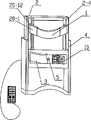
图1是本发明的立体结构示意图;Fig. 1 is the three-dimensional structure schematic diagram of the present invention;
图2是本发明的侧视剖视结构示意图;Fig. 2 is a side view sectional structural representation of the present invention;
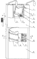
图3是图1中A-A向的剖视结构示意图;Fig. 3 is a schematic cross-sectional structure diagram of A-A direction in Fig. 1;
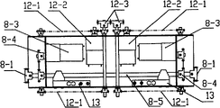
图4是图1中B-B向的剖视结构示意图;Fig. 4 is a schematic cross-sectional structure diagram of B-B direction in Fig. 1;
图5是本发明颈腰托装置的主视结构示意图;Fig. 5 is a front structural schematic view of the neck and waist support device of the present invention;
图6是本发明颈腰托装置的俯视剖面结构示意图;Fig. 6 is a top view sectional structural schematic diagram of the neck and waist support device of the present invention;
图7是本发明颈腰托装置的俯视结构示意图;Fig. 7 is a top structural schematic diagram of the neck and waist support device of the present invention;
图8是本发明支架的主视结构示意图;Fig. 8 is a front view structural schematic diagram of the stent of the present invention;
图9是本发明支架的侧视结构示意图;Fig. 9 is a side view structural schematic diagram of the bracket of the present invention;
图10是本发明实施例1机械手的主视剖面结构示意图;Fig. 10 is a front view sectional structural schematic diagram of the manipulator in
图11是本发明实施例1臂杆的侧视剖面结构示意图;Fig. 11 is a side view sectional structural schematic diagram of the boom of
图12是本发明实施例1机械手的立体结构示意图;Fig. 12 is a schematic diagram of the three-dimensional structure of the manipulator in
图13是本发明实施例2机械手的主视剖面结构示意图;Fig. 13 is a front view sectional structural schematic diagram of the manipulator in
图14是本发明实施例2机械手的动力机构结构示意图;Fig. 14 is a schematic structural view of the power mechanism of the manipulator in
图15是本发明实施例2机械手的立体结构示意图;Fig. 15 is a schematic diagram of the three-dimensional structure of the manipulator according to
图16本发明转盘拉紧机构的结构示意图;Fig. 16 is a schematic structural view of the turntable tensioning mechanism of the present invention;
图17是图12中C-C向的剖视结构示意图。Fig. 17 is a schematic cross-sectional structural diagram of C-C in Fig. 12 .
具体实施方式 Detailed ways
下面结合附图对本发明作进一步说明:The present invention will be further described below in conjunction with accompanying drawing:
实施例1:这种机器人牵引装置,包括座体4、由牵引电机8-3驱动可在座体4上滑动的牵引架2、固定带1、颈腰托组件,其中固定带1、颈腰托组件位于牵引架2上。本实施例是床式的,牵引装置有两组,一组用于颈椎牵引,另一组用于腰椎牵引。Embodiment 1: This robot traction device includes a
颈腰托组件包括颈腰托带3、两个可分别向外侧运动的支架10、两个分别驱动两支架10的颈腰托驱动组件12。支架10包括上固定杆10-16、下固定杆10-13,上固定杆10-16、下固定杆10-13之间撑有两根导杆10-5、一根螺杆10-12,螺杆10-12居中,两导杆10-5位于两侧。支架10上还设有由连接杆10-8、两升降滑杆10-9、升降滑块10-10构成的升降架,其中两升降滑杆10-9撑于连接杆10-8、升降滑块之间10-10,且其与上固定杆10-16呈滑动配合;升降滑块10-10上设有升降螺母10-11,该升降螺母10-11套于螺杆10-12上,颈腰托带3的两端与连接杆10-8固接。这样,调节升降螺母10-11,可将升降架升起,从而调节颈腰托带3的高度。The neck and lumbar support assembly includes a neck and
导杆10-5上套有与其呈滑动配合的导杆滑块10-4,导杆滑块10-4上设有复位弹簧10-7。复位弹簧10-7外侧可套一保护套,保护弹簧。牵引架2两侧设有两根滑轨2-2,支架10通过其两侧的第一牵引滑块10-3、第二牵引滑块10-1与滑轨2-2呈滑动配合;其中第一牵引滑块10-3固接在下固定杆10-13的两端,第二牵引滑块10-1位于第一牵引滑块10-3外侧,且该第二牵引滑块10-1上轴接有撑杆10-2,该撑杆10-2另一端与导杆滑块10-4轴接;第一牵引滑块10-3、第二牵引滑块10-1通过滑块连接件10-6连接在一起,该滑块连接件10-6上开有滑槽10-15,滑槽10-15内穿有两个螺钉10-14,两螺钉10-14分别与第一牵引滑块10-3、第二牵引滑块10-1固接;颈腰托驱动组件12与第二牵引滑块10-1连接。滑轨2-2还可以装上用于限制支架的行程开关,增加安全性。The guide rod slider 10-4 that is slidingly matched with it is sleeved on the guide rod 10-5, and the guide rod slider 10-4 is provided with a back-moving spring 10-7. A protective sleeve can be put on the outside of the back-moving spring 10-7 to protect the spring. Both sides of the
每侧的颈腰托驱动组件12分别包括颈腰托电机12-2、由颈腰托电机12-2驱动的上下两个颈腰托链轮机构12-1,颈腰托链轮机构12-1的传动链条与支架10上的第二牵引滑块10-1固接,两颈腰托驱动组件之间12连接有同步齿轮12-3。牵引架2在正对颈腰托带3处设有测距仪5,用以控制颈腰托带升起的高度。开动两颈腰托电机12-2,即可带动第二牵引滑块10-1向两侧运动,此时撑杆10-2将支架10外侧顶起,避免支架10与牵引架2的碰撞,方便支架10向两侧滑动展开。当第二牵引滑块10-1滑到一定程度时,通过滑块连接件10-6带动第一牵引滑块10-3向两侧滑动,同时撑杆10-2整个支架10慢慢顶起,直至最后立起,此时颈腰托带3已经绷紧,完全托住人体的颈部。牵引结束后,让电机反转,即可将支架10收回至平躺状态。在收回时,复位弹簧10-7便于支架10的复位。因此本发明的颈腰托装置能从平躺状态自动立起托住人体颈部,实现自动化,并且使患者在做牵引时更加舒适。The neck and waist
用于颈椎牵引的固定带1设在两个分别位于牵引架2两侧的机械手7上,该机械手7包括主臂杆7-6、设在主臂杆7-6上且与其呈滑动配合的伸缩臂杆7-5,伸缩臂杆7-5的顶端设有关节座7-3,该关节座7-3内设有转轮7-8,转轮7-8底部设有顶杆7-4,转轮7-8的转轴上套有扭簧7-2;转轮7-8上固接有悬杆7-1,固定带1两端分别固定在两悬杆7-1上;伸缩臂杆7-5上还连接有臂杆伸缩驱动机构。该臂杆伸缩驱动机构包括臂杆伸缩电机14-3,该臂杆伸缩电机14-3通过第一齿轮传动机构14-4与第一转轴14-2连接,第一转轴14-2的两端分别连接有臂杆链轮机构14-1,该臂杆链轮机构14-1的传动链条与伸缩臂杆7-5固接。第一转轴14-2上还设有角度传感器15和转速传感器16,用于控制第一转轴14-2转动的角度和转速。机械手上还连接有臂杆转动机构,该臂杆转动机构包括臂杆转动电机17-5,臂杆转动电机17-5通过第二齿轮传动机构17-4与第二转轴17-3连接,第二转轴17-3的两端固接有转动齿轮17-1,该转动齿轮17-1与角度齿轮17-2连接,角度齿轮17-2与臂杆座7-7同轴,主臂杆7-6设于该臂杆座7-7上。开动臂杆伸缩电机14-3,通过第一齿轮传动机构14-4带动伸缩臂杆7-5滑动,从而使固定带1伸至患者额部,再反转臂杆伸缩电机14-3,即可将固定带1拉紧在患者额部,进行牵引。牵引结束后,再转动臂杆伸缩电机14-3,可将伸缩臂杆7-5收回,当伸缩臂杆7-5收到底时,顶杆7-4受伸缩臂杆7-5的顶壁7-10的限制,使转轮7-8转动,从而带动悬杆7-1竖起,与伸缩臂杆7-5成一直线。扭簧7-2便于在伸缩臂杆7-5前伸时保证悬杆7-1回复原位。此时再开动臂杆转动电机17-5,通过转动齿轮17-1带动臂杆座7-7转动,从而使整个机械手7转动至与牵引架2水平,位于机械手回收槽2-3内。这样,机械手7收回后,整个牵引装置看起来更美观。The
用于腰椎牵引的固定带1设在转盘拉紧机构6上,该转盘拉紧机构6包括拉紧绳6-2、转盘6-3、拉紧电机6-6,拉紧绳6-2穿在固定带1上,拉紧绳6-2的两端穿过一组导向轮6-1后绕在转盘6-3上,该转盘6-3位于牵引架2内;拉紧电机6-6通过第三齿轮传动机构6-5与第三转轴6-7连接,该第三转轴6-7的两端分别与所述的转盘6-3固接。第三转轴6-7上设有离合器6-4。开动拉紧电机6-6,带动转盘6-3转动,从而拉动拉紧绳6-2,最终使固定带1绑紧在患者腹部,进行腰椎牵引。离合器6-4可确保在固定带1过紧时,即可停止转动。The fixed
座体4上开有滑槽4-1,牵引架2上设有与该滑槽4-1相匹配的滑条2-1,该滑条2-1位于滑槽4-1内且与该滑槽4-1呈滑动配合。牵引架2内设有牵引电机8-3,牵引电机8-3通过第四齿轮传动机构8-4与第四转轴8-5连接,该第四转轴8-5的两端固接有牵引齿轮8-1,该牵引齿轮8-1与固定在座体4上的牵引链条8-2配合。牵引链条8-2通过螺钉9固定在座体4上。开动牵引电机8-3,带动牵引齿轮8-1转动,由于牵引链条8-2是固定的,牵引齿轮8-1即可在牵引链条上前进,从而带动整个牵引架2在座体4上滑动,实现牵引。第四转轴8-5上设有拉力传动器13,用于测牵引拉力。牵引架2上可装有行程开关,限制牵引架2的滑动范围。滑槽4-1、滑条2-1的配合,使牵引架2滑动更架平衡。A chute 4-1 is provided on the
使用时,患者躺在座体4上。进行颈椎牵引时,先调整颈腰托装置,使支架10立起,颈腰托带3托住患者颈部。接着调整机械手7,使固定带1绑紧于患者额部。然后开动牵引电机8-3,使牵引架2在座体4上滑动,即可进行颈椎牵引。进行腰椎牵引时,先调整颈腰托装置,使支架10立起,颈腰托带3托住患者腰部。接着调整转盘拉紧机构6,使固定带1绑紧于患者腹部。然后开动牵引电机8-3,使牵引架2在座体4上滑动,即可进行腰椎牵引。During use, the patient lies on the
本机器人牵引装置也可仅用于腰椎牵引,或者仅用于颈椎牵引,此时,只要采用一个牵引装置即可实现。另外,本装置的座体还可以换成椅子,用于颈椎牵引,更加舒适。The robot traction device can also be used only for lumbar vertebra traction, or only for cervical vertebra traction, and at this time, it can be realized as long as one traction device is used. In addition, the seat body of the device can also be replaced with a chair for cervical traction, which is more comfortable.
实施例2:参照图13、14、15,与实施例1不同之处在于:固定带1是橡胶固定带,设在两个分别位于牵引架2两侧的额带导向盒20-1上,并且与该额带导向盒20-1呈滑动配合;额带导向盒20-1内侧设有额带导向转盘20-12,该额带导向转盘20-12套接在位于牵引架2的滑杆2-4上;额带导向转盘20-12内侧连接有滑架20-4,该滑架20-4与牵引架2呈滑动配合;滑架20-4内设有固定带伸缩机构,该固定带伸缩机构包括伸缩电机20-11,伸缩电机20-11通过传动机构20-7驱动两同步轮20-3,该同步轮20-3通过额带链轮机构20-5驱动滚筒20-2,固定带1的内端绕在该滚筒20-2上;滑架20-4内还设有滑移电机20-8,该滑移电机20-8通过滑移传动机构驱动滑移齿轮20-9,该滑移齿轮20-9与固定在座体2上的滑移链条20-6配合。开动伸缩电机20-11,可驱动滚筒20-2转动,从而带动橡胶固定带1伸缩,绑紧或松开患者额带。同步轮20-3保证两侧固定带1伸缩同步。开动滑移电机20-8,可使滑移齿轮20-9转动,由于滑移链条20-6是固定的,整个滑架20-4即可在牵引架2上下移动,调节额带的高度,根据患者的不同身高进行调整。Embodiment 2: With reference to Fig. 13, 14, 15, it is different from Embodiment 1 in that: the fixed belt 1 is a rubber fixed belt, which is arranged on two frontal belt guide boxes 20-1 respectively located on both sides of the traction frame 2, And it is slidingly matched with the forehead belt guide box 20-1; the forehead belt guide box 20-1 is provided with a forehead belt guide turntable 20-12, and the forehead belt guide turntable 20-12 is sleeved on the slide bar located at the traction frame 2 2-4; the inner side of the forehead belt guide turntable 20-12 is connected with a slide frame 20-4, and the slide frame 20-4 is slidingly matched with the traction frame 2; The belt telescopic mechanism includes a telescopic motor 20-11, and the telescopic motor 20-11 drives two synchronous wheels 20-3 through the transmission mechanism 20-7, and the synchronous wheel 20-3 drives the drum 20-2 through the forehead belt sprocket mechanism 20-5, The inner end of the fixed belt 1 is wound on the drum 20-2; a sliding motor 20-8 is also arranged in the carriage 20-4, and the sliding motor 20-8 drives the sliding gear 20-9 through a sliding transmission mechanism. , the sliding gear 20-9 cooperates with the sliding chain 20-6 fixed on the
Claims (10)
Priority Applications (1)
| Application Number | Priority Date | Filing Date | Title |
|---|---|---|---|
| CNB2006100500991A CN100571663C (en) | 2006-03-29 | 2006-03-29 | robot traction device |
Applications Claiming Priority (1)
| Application Number | Priority Date | Filing Date | Title |
|---|---|---|---|
| CNB2006100500991A CN100571663C (en) | 2006-03-29 | 2006-03-29 | robot traction device |
Publications (2)
| Publication Number | Publication Date |
|---|---|
| CN1843311A CN1843311A (en) | 2006-10-11 |
| CN100571663C true CN100571663C (en) | 2009-12-23 |
Family
ID=37062297
Family Applications (1)
| Application Number | Title | Priority Date | Filing Date |
|---|---|---|---|
| CNB2006100500991A Expired - Fee Related CN100571663C (en) | 2006-03-29 | 2006-03-29 | robot traction device |
Country Status (1)
| Country | Link |
|---|---|
| CN (1) | CN100571663C (en) |
Families Citing this family (4)
| Publication number | Priority date | Publication date | Assignee | Title |
|---|---|---|---|---|
| CN111904785B (en) * | 2018-05-07 | 2022-11-15 | 苏州鱼得水电气科技有限公司 | Intermittent lumbar vertebra traction equipment |
| CN111467108A (en) * | 2020-04-21 | 2020-07-31 | 温州市人民医院 | A traction frame for preventing and treating cervical spondylosis at home at the end of the bed |
| CN112545833B (en) * | 2020-12-08 | 2022-09-27 | 四川大学华西医院 | External skeleton robot capable of synchronously drafting shoulder and spine for lumbar vertebra rehabilitation |
| CN119214848B (en) * | 2024-11-28 | 2025-03-04 | 杭州康淼医疗器械科技有限公司 | Six-dimensional cervical vertebra bone setting traction system based on facial gesture recognition technology |
-
2006
- 2006-03-29 CN CNB2006100500991A patent/CN100571663C/en not_active Expired - Fee Related
Also Published As
| Publication number | Publication date |
|---|---|
| CN1843311A (en) | 2006-10-11 |
Similar Documents
| Publication | Publication Date | Title |
|---|---|---|
| CN108852588B (en) | Auxiliary traction device for orthopedics department | |
| CN109431750B (en) | Intracardiac branch of academic or vocational study postoperative rehabilitation and nursing device | |
| CN102247258B (en) | Robot for rehabilitation training of upper and lower limbs | |
| CN110215292B (en) | Bracket device for spine surgery | |
| CN103142388B (en) | Rehabilitation bed for curve traction treatment of lumbar intervertebral disc protrusion | |
| CN110604901B (en) | Auxiliary device for orthopedic rehabilitation | |
| CN101601619B (en) | Multi-functional electric traction, rectification and recovery bed | |
| CN109620636B (en) | Intracardiac branch of academic or vocational study postoperative rehabilitation and nursing trainer | |
| CN108670519B (en) | Electric traction device with adjustable orthopedics is recovered with | |
| CN104224497A (en) | Traction-type hand rehabilitation trainer | |
| CN105662684B (en) | Sextuple cervical vertebrae bone traction recovering system | |
| CN203724417U (en) | Hand rehabilitation training device | |
| CN201216666Y (en) | Computer numerical control photoelectric integrated robot cervical vertebra radian towing mechanism | |
| CN201384600Y (en) | Multifunctional cervical spine rehabilitation therapy instrument | |
| CN205569300U (en) | Brothers microsurgery assisted therapy apparatus | |
| CN113040996A (en) | Intelligent angle-measuring multifunctional cervical spondylosis adjuvant therapy chair | |
| CN201175397Y (en) | Cervical vertebra remedy physiotherapy device | |
| CN204798297U (en) | Passive rehabilitation training device of unilateral upper limbs | |
| CN103845183B (en) | A kind of hand rehabilitation exerciser | |
| CN201609433U (en) | Waist rehabilitation apparatus | |
| CN2870775Y (en) | Robot tractor | |
| CN202314005U (en) | Electric multifunctional nursing bed | |
| CN109364434A (en) | A kind of musculi colli rehabilitation training equipment | |
| CN201551497U (en) | Adjustable spine rehabilitation frame | |
| CN114146376B (en) | Medical rehabilitation training chair |
Legal Events
| Date | Code | Title | Description |
|---|---|---|---|
| C06 | Publication | ||
| PB01 | Publication | ||
| C10 | Entry into substantive examination | ||
| SE01 | Entry into force of request for substantive examination | ||
| C14 | Grant of patent or utility model | ||
| GR01 | Patent grant | ||
| CF01 | Termination of patent right due to non-payment of annual fee | ||
| CF01 | Termination of patent right due to non-payment of annual fee |
Granted publication date: 20091223 Termination date: 20170329 |