BR112015022911B1 - SYSTEMS AND METHODS TO EXPLORE INTERCELLULAR MULTIPLEXATION GAIN IN WIRELESS CELLULAR SYSTEMS THROUGH DISTRIBUTED OUTPUT AND DISTRIBUTED INPUT TECHNOLOGY - Google Patents
SYSTEMS AND METHODS TO EXPLORE INTERCELLULAR MULTIPLEXATION GAIN IN WIRELESS CELLULAR SYSTEMS THROUGH DISTRIBUTED OUTPUT AND DISTRIBUTED INPUT TECHNOLOGY Download PDFInfo
- Publication number
- BR112015022911B1 BR112015022911B1 BR112015022911-5A BR112015022911A BR112015022911B1 BR 112015022911 B1 BR112015022911 B1 BR 112015022911B1 BR 112015022911 A BR112015022911 A BR 112015022911A BR 112015022911 B1 BR112015022911 B1 BR 112015022911B1
- Authority
- BR
- Brazil
- Prior art keywords
- ues
- mas
- distributed
- wireless
- lte
- Prior art date
Links
Images


Classifications
-
- H—ELECTRICITY
- H04—ELECTRIC COMMUNICATION TECHNIQUE
- H04B—TRANSMISSION
- H04B7/00—Radio transmission systems, i.e. using radiation field
- H04B7/02—Diversity systems; Multi-antenna system, i.e. transmission or reception using multiple antennas
- H04B7/022—Site diversity; Macro-diversity
- H04B7/024—Co-operative use of antennas of several sites, e.g. in co-ordinated multipoint or co-operative multiple-input multiple-output [MIMO] systems
-
- H—ELECTRICITY
- H04—ELECTRIC COMMUNICATION TECHNIQUE
- H04B—TRANSMISSION
- H04B7/00—Radio transmission systems, i.e. using radiation field
- H04B7/02—Diversity systems; Multi-antenna system, i.e. transmission or reception using multiple antennas
- H04B7/04—Diversity systems; Multi-antenna system, i.e. transmission or reception using multiple antennas using two or more spaced independent antennas
- H04B7/0413—MIMO systems
- H04B7/0452—Multi-user MIMO systems
-
- H—ELECTRICITY
- H04—ELECTRIC COMMUNICATION TECHNIQUE
- H04J—MULTIPLEX COMMUNICATION
- H04J11/00—Orthogonal multiplex systems, e.g. using WALSH codes
- H04J11/0023—Interference mitigation or co-ordination
- H04J11/0026—Interference mitigation or co-ordination of multi-user interference
- H04J11/003—Interference mitigation or co-ordination of multi-user interference at the transmitter
-
- H—ELECTRICITY
- H04—ELECTRIC COMMUNICATION TECHNIQUE
- H04L—TRANSMISSION OF DIGITAL INFORMATION, e.g. TELEGRAPHIC COMMUNICATION
- H04L25/00—Baseband systems
- H04L25/02—Details ; arrangements for supplying electrical power along data transmission lines
- H04L25/03—Shaping networks in transmitter or receiver, e.g. adaptive shaping networks
- H04L25/03006—Arrangements for removing intersymbol interference
- H04L25/03343—Arrangements at the transmitter end
-
- H—ELECTRICITY
- H04—ELECTRIC COMMUNICATION TECHNIQUE
- H04L—TRANSMISSION OF DIGITAL INFORMATION, e.g. TELEGRAPHIC COMMUNICATION
- H04L25/00—Baseband systems
- H04L25/38—Synchronous or start-stop systems, e.g. for Baudot code
- H04L25/40—Transmitting circuits; Receiving circuits
- H04L25/49—Transmitting circuits; Receiving circuits using code conversion at the transmitter; using predistortion; using insertion of idle bits for obtaining a desired frequency spectrum; using three or more amplitude levels ; Baseband coding techniques specific to data transmission systems
- H04L25/497—Transmitting circuits; Receiving circuits using code conversion at the transmitter; using predistortion; using insertion of idle bits for obtaining a desired frequency spectrum; using three or more amplitude levels ; Baseband coding techniques specific to data transmission systems by correlative coding, e.g. partial response coding or echo modulation coding transmitters and receivers for partial response systems
- H04L25/4975—Correlative coding using Tomlinson precoding, Harashima precoding, Trellis precoding or GPRS
-
- H—ELECTRICITY
- H04—ELECTRIC COMMUNICATION TECHNIQUE
- H04L—TRANSMISSION OF DIGITAL INFORMATION, e.g. TELEGRAPHIC COMMUNICATION
- H04L1/00—Arrangements for detecting or preventing errors in the information received
- H04L1/02—Arrangements for detecting or preventing errors in the information received by diversity reception
- H04L1/06—Arrangements for detecting or preventing errors in the information received by diversity reception using space diversity
-
- H—ELECTRICITY
- H04—ELECTRIC COMMUNICATION TECHNIQUE
- H04L—TRANSMISSION OF DIGITAL INFORMATION, e.g. TELEGRAPHIC COMMUNICATION
- H04L25/00—Baseband systems
- H04L25/02—Details ; arrangements for supplying electrical power along data transmission lines
- H04L25/03—Shaping networks in transmitter or receiver, e.g. adaptive shaping networks
- H04L25/03006—Arrangements for removing intersymbol interference
- H04L2025/0335—Arrangements for removing intersymbol interference characterised by the type of transmission
- H04L2025/03426—Arrangements for removing intersymbol interference characterised by the type of transmission transmission using multiple-input and multiple-output channels
-
- Y—GENERAL TAGGING OF NEW TECHNOLOGICAL DEVELOPMENTS; GENERAL TAGGING OF CROSS-SECTIONAL TECHNOLOGIES SPANNING OVER SEVERAL SECTIONS OF THE IPC; TECHNICAL SUBJECTS COVERED BY FORMER USPC CROSS-REFERENCE ART COLLECTIONS [XRACs] AND DIGESTS
- Y02—TECHNOLOGIES OR APPLICATIONS FOR MITIGATION OR ADAPTATION AGAINST CLIMATE CHANGE
- Y02D—CLIMATE CHANGE MITIGATION TECHNOLOGIES IN INFORMATION AND COMMUNICATION TECHNOLOGIES [ICT], I.E. INFORMATION AND COMMUNICATION TECHNOLOGIES AIMING AT THE REDUCTION OF THEIR OWN ENERGY USE
- Y02D30/00—Reducing energy consumption in communication networks
- Y02D30/70—Reducing energy consumption in communication networks in wireless communication networks
Abstract
SISTEMAS E MÉTODOS PARA EXPLORAR GANHO DE MULTIPLEXAÇÃO INTERCELULAR EM SISTEMAS CELULARES SEM FIO ATRAVÉS DE TECNOLOGIA DE SAÍDA DISTRIBUÍDA E ENTRADA DISTRIBUÍDA. Um sistema de múltiplas antenas (MAS) com transmissões multiusuário (MU) ("MU-MAS") que explora ganho por multiplexação intercelular através de processamento espacial para aumentar a capacidade em redes de comunicações sem fio. Nas últimas três décadas, o mercado de celulares remoto experimentou um número crescente de assinantes no mundo todo, assim, como uma demanda por melhores serviços, variando de voz para navegação na web e transmissão de vídeo em HD por streaming em tempo real. A crescente demanda por serviços que necessitam de taxa de dados mais alta, latência mais baixa e confiabilidade aprimorada tem levado a uma evolução radical das tecnologias sem fio através de diferentes padrões.SYSTEMS AND METHODS TO EXPLOIT INTERCELLULAR MULTIPLEXATION GAIN IN WIRELESS CELLULAR SYSTEMS THROUGH DISTRIBUTED OUTPUT AND DISTRIBUTED INPUT TECHNOLOGY. A multiple-antenna (MAS) system with multi-user (MU) transmissions ("MU-MAS") that exploits intercell multiplexing gain through spatial processing to increase capacity in wireless communications networks. Over the last three decades, the remote mobile market has experienced an increasing number of subscribers worldwide, as well as a demand for better services, ranging from voice to web browsing and HD video streaming to real-time streaming. The growing demand for services that require higher data rate, lower latency and improved reliability has led to a radical evolution of wireless technologies through different standards.
Description
[0001] Este pedido de patente pode estar relacionado aos seguintes Pedidos de Patente dos EUA copendentes/Patentes dos EUA: Pedido de Patente n° US 13/633.702, intitulado “Systems and Methods for wireless backhaul in distributed-input distributed-output wireless systems” Pedido de Patente n° US 13/475.598, intitulado “Systems and Methods to enhance spatial diversity in distributed-input distributed-output wireless systems” Pedido de Patente n° US 13/233.006, intitulado “System and Methods for planned evolution and obsolescence of multiuser spectrum” Pedido de Patente n° US 13/232.996, intitulado “Systems and Methods to Exploit Areas of Coherence in Wireless Systems” Pedido de Patente n° US 13/464.648, intitulado “System and Methods to Compensate for Doppler Effects in Distributed-Input Distributed Output Systems” Pedido de Patente no US 12/917.257, intitulado “Systems And Methods To Coordinate Transmissions In Distributed Wireless Systems Via User Clustering” Pedido de Patente n° US 12/802.988, intitulado “Interference Management, Handoff, Power Control And Link Adaptation In Distributed-Input Distributed-Output (DIDO) Communication Systems” Pedido de Patente n° US 12/802.974, intitulado “System And Method For Managing Inter-Cluster Handoff Of Clients Which Traverse Multiple DIDO Clusters” Pedido de Patente n° US 12/802.989, intitulado “System And Method For Managing Handoff Of A Client Between Different Distributed-Input-Distributed- Output (DIDO) Networks Based On Detected Velocity Of The Client” Pedido de Patente n° US 12/802.958, intitulado “System And Method For Power Control And Antenna Grouping In A Distributed-Input-Distributed-Output (DIDO) Network” Pedido de Patente n° US 12/802.975, intitulado “System And Method For Link adaptation In DIDO Multicarrier Systems” Pedido de Patente n° US 12/802.938, intitulado “System And Method For DIDO Precoding Interpolation In Multicarrier Systems” Pedido de Patente n° US 12/630.627, intitulado “System and Method For Distributed Antenna Wireless Communications” Patente n° US 8.170.081, emitida em 1 de maio de 2012, intitulada “System And Method For Adjusting DIDO Interference Cancellation Based On Signal Strength Measurements” Patente n° US 8.160.121, emitida em 17 de abril de 2012, intitulada, “System and Method For Distributed Input-Distributed Output Wireless Communications”; Patente n° US 7.885.354, emitida em 8 de fevereiro de 2011, intitulada “System and Method For Enhancing Near Vertical Incidence Skywave (“NVIS”) Communication Using Space-Time Coding”. Patente n° US 7.711.030, emitida em 4 de maio de 2010, intitulada “System and Method For Spatial-Multiplexed Tropospheric Scatter Communications”; Patente n° US 7.636.381, emitida em 22 de dezembro de 2009, intitulada “System and Method for Distributed Input Distributed Output Wireless Communication”; Patente n° US 7.633.994, emitida em 15 de dezembro de 2009, intitulada “System and Method for Distributed Input Distributed Output Wireless Communication”; Patente n° US 7.599.420, emitida em 06 de outubro de 2009, intitulada “System and Method for Distributed Input Distributed Output Wireless Communication”; Patente n° US 7.418.053, emitida em 26 de agosto de 2008, intitulada “System and Method for Distributed Input Distributed Output Wireless Communication”;[0001] This patent application may be related to the following copending US Patent Applications/US Patents: Patent Application No. US 13/633,702 entitled “Systems and Methods for wireless backhaul in distributed-input distributed-output wireless systems ” Patent Application No. US 13/475,598, entitled “Systems and Methods to enhance spatial diversity in distributed-input distributed-output wireless systems” Patent Application No. US 13/233,006, entitled “System and Methods for planned evolution and obsolescence of multiuser spectrum” US Patent Application No. 13/232,996, entitled “Systems and Methods to Exploit Areas of Coherence in Wireless Systems” US Patent Application No. 13/464,648, entitled “System and Methods to Compensate for Doppler Effects in Distributed -Input Distributed Output Systems” US Patent Application 12/917,257, entitled “Systems And Methods To Coordinate Transmissions In Distributed Wireless Systems Via User Clustering” US Patent Application 12/802,988, entitled “Interference Management, Handoff, Power Control And Link Adaptation In Distributed-Input Distributed-Output (DIDO) Communication Systems” Patent Application No. US 12/802,974, entitled “System And Method For Managing Inter-Cluster Handoff Of Clients Which Traverse Multiple DIDO Clusters” Patent Application No. US 12/802,989, entitled “System And Method For Managing Handoff Of A Client Between Different Distributed-Input-Distributed-Output (DIDO) Networks Based On Detected Velocity Of The Client” Patent Application No. US 12/802,958, entitled “System And Method For Power Control And Antenna Grouping In A Distributed-Input-Distributed-Output (DIDO) Network” Patent Application No. US 12/802,975, entitled “System And Method For Link Adaptation In DIDO Multicarrier Systems” Patent Application No. US 12/802,938, entitled “System And Method For DIDO Precoding Interpolation In Multicarrier Systems” Patent Application No. US 12/630,627, entitled “System and Method For Distributed Antenna Wireless Communications” US Patent No. 8,170,081, issued on 1 May 2012, entitled “System And Method For Adjusting DIDO Interference Cancellation Based On Signal Strength Measurements” US Patent No. 8,160,121, Issued April 17, 2012, entitled, “System and Method For Distributed Input-Distributed Output Wireless Communications”; US Patent No. 7,885,354, issued February 8, 2011, entitled “System and Method For Enhancing Near Vertical Incidence Skywave (“NVIS”) Communication Using Space-Time Coding”. US Patent No. 7,711,030, issued May 4, 2010, entitled “System and Method For Spatial-Multiplexed Tropospheric Scatter Communications”; US Patent No. 7,636,381, issued December 22, 2009, entitled “System and Method for Distributed Input Distributed Output Wireless Communication”; US Patent No. 7,633,994, issued December 15, 2009, entitled “System and Method for Distributed Input Distributed Output Wireless Communication”; US Patent No. 7,599,420, issued on October 6, 2009, entitled “System and Method for Distributed Input Distributed Output Wireless Communication”; US Patent No. 7,418,053, issued August 26, 2008, entitled “System and Method for Distributed Input Distributed Output Wireless Communication”;
[0002] Nas últimas três décadas, o mercado de celulares sem fio tem experimentado um aumento do número de assinantes em todo o mundo, bem como a demanda por melhores serviços, oscilando entre voz para navegação na web e transmissão de vídeo em HD por streaming em tempo real. A crescente demanda por serviços que necessitam de taxa de dados mais alta, latência mais baixa e confiabilidade aprimorada tem levado a uma evolução radical das tecnologias sem fio através de diferentes padrões. Começando a partir da primeira geração de AMPS e TACS analógicos (para serviço de voz) no início de 1980, para GSM digital de 2G e 2.5G, IS-95 e GPRS (para serviços de voz e dados) na década de 1990, a 3G com UMTS e CDMA2000 (para navegação na web) no início de 2000 e, finalmente, LTE (para conectividade de alta velocidade à Internet) atualmente em implantação em diferentes países do mundo.[0002] Over the last three decades, the wireless cell phone market has experienced an increase in the number of subscribers worldwide, as well as demand for better services, ranging from voice for web browsing to streaming HD video In real time. The growing demand for services that require higher data rate, lower latency and improved reliability has led to a radical evolution of wireless technologies through different standards. Starting from the first generation of analogue AMPS and TACS (for voice service) in the early 1980s, to 2G and 2.5G digital GSM, IS-95 and GPRS (for voice and data services) in the 1990s, 3G with UMTS and CDMA2000 (for web browsing) in the early 2000s, and finally LTE (for high-speed Internet connectivity) currently being rolled out in different countries around the world.
[0003] A Evolução a longo prazo (LTE) é o padrão desenvolvido pelo projeto de parceria de terceira geração (3GPP) para sistemas de celulares sem fio de quarta geração (4G). A LTE pode atingir, teoricamente, uma melhoria de até 4x em eficiência espectral de enlace descendente sobre o 3G e os padrões HSPA + anteriores através da exploração dos componentes espaciais de canais sem fio por meio da tecnologia de múltiplas entradas e múltiplas saídas (MIMO). A LTE- Avançada é a evolução da LTE, atualmente sob padronização, que permitirá, teoricamente, aumento de até 8x na eficiência espectral em sistemas 3G padrão.[0003] Long Term Evolution (LTE) is the standard developed by the Third Generation Partnership Project (3GPP) for fourth generation wireless cellular systems (4G). LTE can theoretically achieve up to a 4x improvement in downlink spectral efficiency over 3G and previous HSPA+ standards by exploiting the spatial components of wireless channels via multiple-input, multiple-output (MIMO) technology. . LTE-Advanced is the evolution of LTE, currently under standardization, which will theoretically allow for up to 8x increase in spectral efficiency in standard 3G systems.
[0004] Apesar desta evolução da tecnologia, é muito provável que as operadoras sem fio dos próximos três anos não sejam capazes de satisfazer a procura crescente por taxa de dados devido à penetração crescente no mercado de telefones inteligentes e computadores do tipo tablet, oferecer mais aplicativos que exijam grandes quantidades de dados, como transmissão de vídeo em HD por streaming em tempo real, conferência em vídeo e jogos. Estima-se que a capacidade de redes sem fio irá crescer 5x na Europa de 2011 a 2015 devido à melhora de tecnologias, como LTE, bem como mais espectro disponibilizado pelo governo [25]. Por exemplo, a FCC está planejando liberar 500 MHz de espectro até 2020 (dos quais 300 MHz estarão disponíveis em 2015) para promover a conectividade com a Internet sem fio em todo os EUA como parte do Plano Nacional de Banda Larga [24]. Infelizmente, a previsão para uso da capacidade até 2015 é 23x a mais em 2011 na Europa [25], e um déficit de espectro semelhante está previsto para acontecer nos EUA em 2014 [26-27]. Como resultado desta crise de dados, as receitas para operadoras de telefonia móvel podem cair abaixo do seu CAPEX e OPEX, com impacto potencialmente devastador sobre o mercado de telefonia móvel [28].[0004] Despite this evolution of technology, it is very likely that wireless operators in the next three years will not be able to satisfy the increasing demand for data rate due to the increasing market penetration of smart phones and tablet computers, offer more applications that require large amounts of data, such as real-time streaming HD video streaming, video conferencing, and gaming. It is estimated that wireless network capacity will grow 5x in Europe from 2011 to 2015 due to improved technologies such as LTE as well as more spectrum being made available by the government [25]. For example, the FCC is planning to release 500 MHz of spectrum by 2020 (of which 300 MHz will be available in 2015) to promote wireless Internet connectivity across the US as part of the National Broadband Plan [24]. Unfortunately, the forecast for capacity usage by 2015 is 23x more than 2011 in Europe [25], and a similar spectrum shortfall is predicted to happen in the US in 2014 [26-27]. As a result of this data crisis, revenues for mobile operators could fall below their CAPEX and OPEX, with potentially devastating impact on the mobile market [28].
[0005] Como os ganhos de capacidade oferecidos pela implantação de LTE e disponibilidade aumentada de espectro são insuficientes, a única solução previsível para evitar esta crise de espectro em proximidade é promover novas tecnologias sem fio [29]. A LTE-Avançada (a evolução do padrão de LTE) promete ganhos adicionais sobre LTE através de técnicas MIMO mais sofisticadas e através do aumento da densidade de “pequenas células” [30]. No entanto, há limites para o número de células que podem se encaixar em uma determinada área sem incorrer em problemas de interferência ou aumentar a complexidade do backhaul para permitir a coordenação através das células.[0005] As the capacity gains offered by the deployment of LTE and increased spectrum availability are insufficient, the only foreseeable solution to avoid this near spectrum crisis is to promote new wireless technologies [29]. LTE-Advanced (the evolution of the LTE standard) promises additional gains over LTE through more sophisticated MIMO techniques and through increased “small cell” density [30]. However, there are limits to the number of cells that can fit in a given area without incurring interference issues or increasing backhaul complexity to allow coordination across cells.
[0006] Uma tecnologia promissora que irá fornecer ordens de aumento de magnitude na eficiência espectral sobre ligações sem fio sem as limitações dos sistemas convencionais de celulares é a tecnologia de entrada distribuída e saída distribuída (DIDO) (ver patentes e pedidos relacionados acima referenciados em [0002 a 0020]. A presente invenção descreve a tecnologia DIDO empregada no contexto de sistemas celulares (como LTE ou LTE-Avançada), tanto dentro quanto fora das restrições de padrões celulares, para proporcionar benefícios de desempenho significativos sobre sistemas sem fio convencionais. Começamos com uma visão geral sobre MIMO e revisão de diferentes técnicas de processamento espaciais empregadas por LTE e LTE-Avançada. Então, é mostrado como a presente invenção proporciona ganhos de capacidade significativos para os sistemas de comunicação sem fio da próxima geração, em comparação com abordagens da técnica anterior.[0006] A promising technology that will provide orders of magnitude increases in spectral efficiency over wireless links without the limitations of conventional cellular systems is distributed input distributed output (DIDO) technology (see related patents and applications referenced above at [0002 to 0020] The present invention describes DIDO technology employed in the context of cellular systems (such as LTE or LTE-Advanced), both within and outside the constraints of cellular standards, to provide significant performance benefits over conventional wireless systems. We start with an overview of MIMO and review different spatial processing techniques employed by LTE and LTE-Advanced. Then, it is shown how the present invention provides significant capacity gains for next generation wireless communication systems, compared to prior art approaches.
[0007] A MIMO emprega múltiplas antenas nos lados do transmissor e receptor da ligação sem fio e usa processamento espacial para melhorar a confiabilidade de ligação através de técnicas de diversidade (ou seja, ganho de diversidade) ou fornece uma maior taxa de dados através de esquemas de multiplexação (ou seja, ganho por multiplexação) [1 a 2]. O ganho de diversidade é uma medida da robustez melhorada para o desvanecimento do sinal, resultando em maior razão de sinal-para- ruído (SNR) para taxa de dados fixa. O ganho de multiplexação é obtido pela exploração de graus espaciais adicionais de liberdade do canal sem fio para aumentar a taxa de dados para a probabilidade de erro fixa. As compensações fundamentais entre diversidade e multiplexação em sistemas MIMO foram descritas em [3 a 4].[0007] MIMO employs multiple antennas on the transmitter and receiver sides of the wireless link and uses spatial processing to improve link reliability through diversity techniques (i.e., diversity gain) or provide a higher data rate through multiplexing schemes (ie gain by multiplexing) [1 to 2]. Diversity gain is a measure of improved robustness to signal fading, resulting in higher signal-to-noise ratio (SNR) for fixed data rate. Multiplexing gain is achieved by exploiting additional spatial degrees of freedom of the wireless channel to increase the data rate for the fixed error probability. The fundamental tradeoffs between diversity and multiplexing in MIMO systems have been described in [3 to 4].
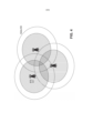
[0008] Em sistemas MIMO práticos, as técnicas de adaptação de ligação podem ser usadas para alternar dinamicamente entre esquemas de diversidade e multiplexação, com base nas condições de propagação [20 a 23]. Por exemplo, os esquemas de adaptação de enlace descritos em [22 a 23] mostraram que a formação de feixe ou Códigos de Bloco de Tempo-Espaço Ortogonais (OSTBC) são os esquemas preferencias no regime de baixa SNR ou canais caracterizados pela baixa seletividade espacial. Em contrapartida, a multiplexação espacial pode fornecer ganho significativo na taxa de dados para canais com alta SNR e alta seletividade espacial. Por exemplo, a Figura 1 mostra que as células podem ser divididas em duas regiões: i) região de multiplexação 101, caracterizada pela elevada SNR (devido à proximidade com a torre de célula ou estação de base), onde os graus espaciais de liberdade do canal podem ser explorados através de multiplexação espacial para aumentar a taxa de dados; ii) região de diversidade 102 ou borda de célula, onde técnicas espaciais de multiplexação não são tão eficazes e métodos de diversidade podem ser usados para melhorar a SNR e a cobertura (gerando apenas aumento marginal na taxa de dados). Observa-se que o círculo da macrocélula 103 na Figura 1 rotula o centro sombreado do círculo como a “região de multiplexação” e a região exterior não sombreada do círculo como a região de “diversidade”. Essa mesma região de designação é usada ao longo das Figuras 1,3 a 5, onde a região sombreada representa a “região de multiplexação” e a região não sombreada representa a “região de diversidade”, mesmo que elas não estejam rotuladas. Por exemplo, a mesma designação é usada para a célula pequena 104 na Figura 1.[0008] In practical MIMO systems, link adaptation techniques can be used to dynamically switch between diversity and multiplexing schemes, based on propagation conditions [20 to 23]. For example, the link adaptation schemes described in [22 to 23] showed that beamforming or Orthogonal Time-Space Block Codes (OSTBC) are the preferred schemes in the low SNR regime or channels characterized by low spatial selectivity. . In contrast, spatial multiplexing can provide significant gain in data rate for channels with high SNR and high spatial selectivity. For example, Figure 1 shows that cells can be divided into two regions: i) multiplexing region 101, characterized by high SNR (due to proximity to the cell tower or base station), where the spatial degrees of freedom of the channel can be exploited through spatial multiplexing to increase the data rate; ii) diversity region 102 or cell edge, where spatial multiplexing techniques are not as effective and diversity methods can be used to improve SNR and coverage (generating only marginal increase in data rate). Note that the circle of macrocell 103 in Figure 1 labels the shaded center of the circle as the “multiplexing region” and the outer unshaded region of the circle as the “diversity” region. This same designation region is used throughout Figures 1, 3 to 5, where the shaded region represents the “multiplexing region” and the unshaded region represents the “diversity region”, even though they are not labeled. For example, the same designation is used for small cell 104 in Figure 1.
[0009] Os padrões de LTE (versão 8) e LTE-Avançada (versão 10) definem um conjunto de dez modos de transmissão (TM) incluindo qualquer esquema de diversidade ou multiplexação [35, 85 a 86]: • Modo 1 Única porta de antena, porta 0 • Modo 2 Diversidade de transmissão • Modo 3 Diversidade de atraso cíclico de grande atraso (CDD), extensão da multiplexação espacial de circuito aberto para MIMO de único usuário (SU-MIMO) • Modo 4 Multiplexação espacial de circuito fechado para SU-MIMO • Modo 5 MIMO de multiusuário (MU-MIMO) • Modo 6 Multiplexação espacial de circuito fechado, usando uma única camada de transmissão • Modo 7 Única porta de antena, RS de UE específico (porta 5) • Modo 8 Transmissão de camada única ou dupla com RS de UE específico (portas 7 e/ou 8) • Modo 9 SU-MIMO de circuito fechado de camada única ou até oito camadas (adicionado na Versão 10) • Modo 10 SU-MIMO de circuito fechado de multicamada, até oito camadas (adicionado na Versão 10)[0009] The LTE (version 8) and LTE-Advanced (version 10) standards define a set of ten transmission modes (TM) including any diversity or multiplexing scheme [35, 85 to 86]: •
[0010] Adiante, são descritos os esquemas de diversidade e multiplexação normalmente usados em sistemas celulares, bem como métodos específicos empregados na LTE, conforme destacado acima, e compara-se os mesmos contra técnicas que são exclusivas para comunicações DIDO. Identificou-se primeiro dois tipos de métodos de transmissão: i) métodos intracelulares (explorando a microdiversidade em sistemas celulares), usando várias antenas para melhorar a confiabilidade do enlace ou taxa de dados dentro de uma célula; ii) métodos intercelulares (explorando macrodiversidade), permitindo a cooperação entre as células para proporcionar diversidade adicional ou ganhos de multiplexação. Em seguida, é descrita a forma como a presente invenção fornece vantagens significativas (incluindo ganho de capacidade espectral) sobre a técnica anterior.[0010] Below, diversity and multiplexing schemes commonly used in cellular systems are described, as well as specific methods employed in LTE, as highlighted above, and compared against techniques that are exclusive to DIDO communications. Two types of transmission methods were first identified: i) intracellular methods (exploiting the micro-diversity in cellular systems), using multiple antennas to improve link reliability or data rate within a cell; ii) intercellular methods (exploiting macrodiversity), allowing cooperation between cells to provide additional diversity or multiplexing gains. Next, it is described how the present invention provides significant advantages (including gains in spectral capacity) over the prior art.
[0011] Os métodos de diversidade intracelular operam dentro de uma célula e são projetados para aumentar a SNR em cenários com baixa qualidade de ligação (por exemplo, os usuários na borda de célula sujeitos à perda de trajeto da torre central ou estação base). Os esquemas de diversidade típicos utilizados em comunicações MIMO são formação de feixe [5 a 11] e códigos de bloco de espaço-tempo ortogonais (OSTBC) [12 a 15].[0011] Intracellular diversity methods operate within a cell and are designed to increase SNR in scenarios with poor link quality (for example, users at the cell edge subject to path loss from the central tower or base station). Typical diversity schemes used in MIMO communications are beamforming [5 to 11] and Orthogonal Spacetime Block (OSTBC) codes [12 to 15].
[0012] As técnicas de diversidade suportadas pelo padrão de LTE são diversidade de transmissão, pré-codificação de nível 1 de circuito fechado e formação de feixe dedicada [31 a 35]. O esquema de diversidade de transmissão suporta duas ou quatro antenas de transmissão sobre o enlace descendente (DL) e apenas duas antenas para o enlace ascendente (UL). No canal de DL, implementa-se através de códigos de bloco de espaço-frequência (SFBC) combinados com a diversidade de transmissão comutada por frequência (FSTD) para explorar o espaço, bem como a seletividade de frequência [31]. A pré-codificação nível 1 cria um feixe dedicado a um usuário baseado em pesos quantizados, selecionados a partir de um livro de códigos (pré-projetado usando técnicas limitadas de retroalimentação [36 a 42]) para reduzir a sobrecarga de retroalimentação do equipamento de usuário (UE) para a estação base do transceptor (BTS 105 na Figura 1, ou eNodeB usando terminologia LTE). Alternativamente, os pesos de formação de feixe dedicados podem ser calculados com base no sinal de referência específico de UE.[0012] The diversity techniques supported by the LTE standard are transmit diversity, closed
[0013] Os esquemas de multiplexação MIMO [1, 19] fornecem ganho na taxa de dados em regime SNR elevado e em cenários com graus espaciais suficientes de liberdade no canal (por exemplo, ambientes ricos de múltiplos caminhos com alta seletividade espacial [16 a 18]) para suportar múltiplos fluxos de dados paralelos através de ligações sem fio.[0013] MIMO multiplexing schemes [1, 19] provide data rate gain in high SNR regime and in scenarios with sufficient spatial degrees of freedom in the channel (for example, rich multipath environments with high spatial selectivity [16 to 18]) to support multiple parallel data streams over wireless links.
[0014] O padrão de LTE suporta diferentes técnicas de multiplexação para MIMO de usuário único (SU-MIMO) e MIMO multiusuário (MU-MIMO) [31]. Os esquemas SU-MIMO têm dois modos de operação: i) circuito fechado, explorando informações de retroalimentação a partir do UE para selecionar os pesos de precodificação de DL; ii) circuito aberto, usado quando a retroalimentação do UE não está disponível ou o UE está se movendo muito rápido para suportar esquemas de circuito fechado. Os esquemas de circuito fechado utilizam um conjunto de pesos pré-computados selecionados a partir de um livro de códigos. Esses pesos podem suportar duas ou quatro antenas de transmissão, bem como um a quatro fluxos de dados paralelos (identificados pelo número de camadas da matriz de pré-codificação), dependendo do pedido do UE e decisão do programador na BTS. A LTE-Avançada vai incluir novos modos de transmissão até MIMO 8x8 para fornecer até 8x de aumento da eficiência espectral através do processamento espacial [62].[0014] The LTE standard supports different multiplexing techniques for single-user MIMO (SU-MIMO) and multi-user MIMO (MU-MIMO) [31]. SU-MIMO schemes have two modes of operation: i) closed loop, exploiting feedback information from the UE to select DL precoding weights; ii) open loop, used when UE feedback is not available or the UE is moving too fast to support closed loop schemes. Closed-loop schemes use a set of precomputed weights selected from a codebook. These weights can support two or four transmit antennas, as well as one to four parallel data streams (identified by the number of layers in the precoding matrix), depending on the UE request and programmer decision in the BTS. LTE-Advanced will include new transmission modes up to 8x8 MIMO to provide up to 8x increased spectral efficiency through spatial processing [62].
[0015] Os esquemas MU-MIMO são definidos tanto para canais de UL quanto de DL [31, 50]. No UL, cada UE envia um sinal de referência para a BTS (consistindo na versão deslocada ciclicamente da sequência Zadoff-Chu [33]). Esses sinais de referência são ortogonais, de tal modo que a BTS pode estimar o canal a partir de todos os UEs e demodular fluxos de dados a partir de múltiplos UEs simultaneamente através de processamento espacial. No DL, os pesos de pré- codificação para diferentes UEs são selecionados dentre livros de código com base na retroalimentação dos UEs e do programador (semelhante aos esquemas SU- MIMO de circuito fechado), e apenas a pré-codificação da classe 1 é permitida para cada UE (por exemplo, cada UE recebe apenas um fluxo de dados).[0015] MU-MIMO schemes are defined for both UL and DL channels [31, 50]. In the UL, each UE sends a reference signal to the BTS (consisting of the cyclically shifted version of the Zadoff-Chu sequence [33]). These reference signals are orthogonal such that the BTS can estimate the channel from all UEs and demodulate data streams from multiple UEs simultaneously through spatial processing. In DL, precoding weights for different UEs are selected from among codebooks based on feedback from UEs and the programmer (similar to closed-loop SUMIMO schemes), and only
[0016] As técnicas de multiplexação intracelular que empregam processamento espacial fornecem desempenho satisfatório apenas em cenários de propagação caracterizados pela alta SNR (ou SINR) e alta seletividade espacial (ambientes ricos em caminhos múltiplos). Para macrocélulas convencionais, essas condições podem ser mais difíceis de alcançar, já que as BTSs são tipicamente medidas a partir dos UEs e a distribuição da SINR é tipicamente centrada em valores baixos [43]. Nesses cenários, os esquemas MU-MIMO ou técnicas de diversidade podem ser melhores escolhas do que SU-MIMO com multiplexação espacial.[0016] Intracellular multiplexing techniques that employ spatial processing provide satisfactory performance only in propagation scenarios characterized by high SNR (or SINR) and high spatial selectivity (rich multipath environments). For conventional macrocells, these conditions may be more difficult to achieve, as the BTSs are typically measured from the UEs and the SINR distribution is typically centered on low values [43]. In these scenarios, MU-MIMO schemes or diversity techniques may be better choices than SU-MIMO with spatial multiplexing.
[0017] As outras técnicas e soluções de rede contempladas por LTE-Avançada para atingir ganho adicional de multiplexação (sem exigir processamento espacial através de MIMO) são: agregação de operadora (CA) e células pequenas. A CA [30, 44 a 47] combina porções diferentes do espectro de RF para aumentar a largura de banda do sinal até 100 MHz [85], obtendo-se, assim, taxas de dados mais elevadas. A CA intrabanda combina diferentes bandas na mesma porção do espectro. Desse modo, pode-se utilizar a mesma cadeia de RF para múltiplos canais, e os vários fluxos de dados são recombinados no software. A CA interbanda requer diferentes cadeias de RF para operar em diferentes partes do espectro, bem como o processamento de sinal para recombinar vários fluxos de dados a partir de diferentes bandas.[0017] The other network techniques and solutions contemplated by LTE-Advanced to achieve additional multiplexing gain (without requiring spatial processing through MIMO) are: carrier aggregation (CA) and small cells. AC [30, 44 to 47] combines different portions of the RF spectrum to increase the signal bandwidth up to 100 MHz [85], thus obtaining higher data rates. Inband AC combines different bands in the same portion of the spectrum. In this way, the same RF chain can be used for multiple channels, and the various data streams are recombined in the software. Interband AC requires different RF chains to operate in different parts of the spectrum, as well as signal processing to recombine various data streams from different bands.
[0018] A ideia principal de células pequenas [30, 47] é reduzir o tamanho das macrocélulas convencionais, permitindo, assim, densidade celular mais elevada e maior velocidade por área de cobertura. As células pequenas são tipicamente implantadas através de pontos de acesso de baixo custo 106, com transmissão de baixa potência (conforme representado na Figura 1) ao invés de torres de celular altas e dispendiosas usadas para macrocélulas. Dois tipos de células pequenas são definidos na LTE-Avançada: i) metrocélulas, para instalação ao ar livre em áreas urbanas, suportando até 32 a 64 usuários simultâneos; e ii) femtocélulas, para uso interno, podem servir, no máximo, 4 usuários ativos. Uma vantagem das células pequenas é que a densidade de UEs perto da BTS é estatisticamente mais elevada, obtendo-se melhor SNR, que pode ser explorada por meio da multiplexação espacial para aumentar a taxa de dados. Há, porém, ainda muitas preocupações sobre a implantação prática de células pequenas, particularmente, relacionadas ao backhaul. Na verdade, pode ser difícil de alcançar a BTS de cada pequena célula por meio de conexões fixas de alta velocidade, especialmente considerando a elevada densidade de metrocélulas e femtocélulas em uma determinada área de cobertura. Embora a utilização do backhaul de Linha-de-Visão (LOS) para células pequenas muitas vezes possa ser implementada de forma pouco dispendiosa, em comparação com o backhaul de rede fixa, muitas vezes não há trajetórias de backhaul de LOS práticas disponíveis para colocações de BTS de pequenas células preferidas, e não existe uma solução geral para o backhaul sem fio de Não-Linha-de-Visão (NLOS) para BTSs de pequenas células. Além disso, as células pequenas exigem coordenação complexa em tempo real através dos BTSs para evitar interferência, como em redes auto-organizadas (SON) [30, 51-52] e ferramentas sofisticadas de planejamento de célula (ainda mais complexas do que sistemas convencionais de celulares, devido à maior densidade de células pequenas) para planejar a sua localização ideal [48, 49]. Finalmente, a transferência é um fator limitante para a implantação de células pequenas, especialmente em cenários onde grupos de assinantes alternam as células ao mesmo tempo, causando grande quantidade de sobrecarga de transferência no backhaul, resultando em alta latência e inevitáveis chamadas interrompidas.[0018] The main idea of small cells [30, 47] is to reduce the size of conventional macrocells, thus allowing higher cell density and greater velocity per coverage area. Small cells are typically deployed via low-
[0019] Pode ser trivialmente demonstrado que não há nenhuma solução prática geral que permita que células pequenas coexistam com macrocélulas e atingir uma velocidade ideal, ou mesmo necessariamente melhorada. Entre a infinidade de tais situações insolúveis está aquela quando uma pequena célula é localizada de modo que seus UEs sobrepõem-se inevitavelmente com uma transmissão de macrocélula, e a célula pequena e a macrocélula usam as mesmas frequências para alcançar seus respectivos UEs. É evidente que, nesta situação, a transmissão da macrocélula irá interferir com a transmissão de pequenas células. Embora possa haver alguma abordagem que atenue tal interferência para circunstâncias específicas de uma macrocélula particular, uma pequena célula particular, da macrocélula particular e UEs de pequenas células envolvidos, dos requisitos velocidade desses UEs, e das circunstâncias ambientais, etc., tal abordagem permitiria ser altamente específica, não só para o plano estático da macrocélula e célula pequena, mas para as circunstâncias dinâmicas de um determinado intervalo de tempo. Tipicamente, a velocidade completa do canal para cada UE não pode ser alcançada.[0019] It can be trivially demonstrated that there is no general practical solution that would allow small cells to coexist with macrocells and achieve optimal, or even necessarily improved, speed. Among the multitude of such unsolvable situations is that when a small cell is located such that its UEs inevitably overlap with a macrocell transmission, and the small cell and the macrocell use the same frequencies to reach their respective UEs. Clearly, in this situation, macrocell transmission will interfere with small cell transmission. While there may be some approach that mitigates such interference for the specific circumstances of a particular macrocell, a particular small cell, the particular macrocell and small cell UEs involved, the speed requirements of those UEs, and the environmental circumstances, etc., such an approach would allow it to be highly specific, not only for the static plane of the macrocell and small cell, but for the dynamic circumstances of a given time interval. Typically, the full channel speed for each UE cannot be achieved.
[0020] Em uma rede heterogênea (HetNet) [90] onde macrocélulas coexistem com células pequenas (por exemplo, metrocélulas, picocélulas e femtocélulas) é necessário empregar diferentes técnicas para eliminar a interferência intercelular. Embora HetNets forneçam melhor cobertura através de células pequenas, os ganhos na taxa de dados são apenas marginais, já que exigem o compartilhamento do espectro através de diferentes formas de padrões de reuso de frequência ou uso de processamento espacial para remover interferências em vez de atingir ganho de multiplexação. Os padrões de LTE empregam esquemas de coordenação de interferência intercelular (ICIC) para remover interferência, particularmente, na borda de célula. Existem dois tipos de métodos ICIC: célula autónoma e coordenada entre BTSs.[0020] In a heterogeneous network (HetNet) [90] where macrocells coexist with small cells (eg metrocells, picocells and femtocells) it is necessary to employ different techniques to eliminate intercellular interference. Although HetNets provide better coverage across small cells, the gains in data rate are only marginal as they require sharing the spectrum through different forms of frequency reuse patterns or using spatial processing to remove interference rather than achieving gain. of multiplexing. LTE standards employ intercellular interference coordination (ICIC) schemes to remove interference, particularly at the cell edge. There are two types of ICIC methods: autonomous cell and coordinated between BTSs.
[0021] Os esquemas de ICIC de célula autónoma evitam a interferência intercelular através de diferentes padrões de reuso de frequência representados na Figura 2, onde os hexágonos representam as células e as cores referem-se às diferentes frequências de operadoras. Três tipos de esquemas são considerados em LTE: i) reuso de frequência completa (ou reuso 1), onde as células utilizam toda a largura de banda disponível, como na Figura 2a, assim, produzindo alta interferência na borda da célula; ii) reuso intenso de frequência (HFR), onde cada célula é atribuída a uma faixa de frequência diferente, como na Figura 2b (com fator de reuso típico de 3) para evitar interferência entre células adjacentes; iii) reuso de frequência fracionário (FFR), onde o centro da célula é atribuído à largura de banda disponível total, como no reuso de frequência 1, considerando que a borda da célula opera no modo HFR para atenuar a interferência intercelular, como na Figura 2c.[0021] The autonomous cell ICIC schemes avoid intercellular interference through different frequency reuse patterns represented in Figure 2, where the hexagons represent the cells and the colors refer to the different carrier frequencies. Three types of schemes are considered in LTE: i) full frequency reuse (or reuse 1), where cells use all available bandwidth, as in Figure 2a, thus producing high interference at the cell edge; ii) intense frequency reuse (HFR), where each cell is assigned to a different frequency range, as in Figure 2b (with typical reuse factor of 3) to avoid interference between adjacent cells; iii) fractional frequency reuse (FFR), where the center of the cell is assigned to the total available bandwidth, as in
[0022] Métodos de ICIC coordenados permitem cooperação através de BTSs para melhorar o desempenho de redes sem fio. Essas técnicas são um caso especial de métodos ensinado nas Patentes e Pedidos relacionados [0002 a 0022] para permitir a cooperação entre transceptores sem fio no caso geral de redes de antenas distribuídas para vários UEs, todos usando a mesma frequência simultaneamente. A cooperação entre as BTSs para remover a interferência entre células para o caso particular de sistemas celulares para um único UE em um dado momento a uma dada frequência foi descrita em [53]. O sistema em [53] divide cada macrocélula em várias subcélulas e permite a transferência suave através das subcélulas empregando a formação de feixe dedicada a partir das BTSs coordenadas para melhorar a robustez do enlace em um único UE em uma única frequência, na medida em que se move ao longo dos limites da subcélula.[0022] Coordinated ICIC methods allow cooperation across BTSs to improve the performance of wireless networks. These techniques are a special case of methods taught in related Patents and Applications [0002 to 0022] to allow cooperation between wireless transceivers in the general case of distributed antenna networks for several UEs, all using the same frequency simultaneously. Cooperation between BTSs to remove intercell interference for the particular case of cellular systems for a single UE at a given time at a given frequency has been described in [53]. The system in [53] divides each macrocell into several subcells and allows smooth transfer across the subcells by employing dedicated beamforming from the coordinated BTSs to improve the link robustness in a single UE at a single frequency, as moves along subcell boundaries.
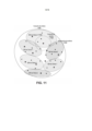
[0023] Mais recentemente, essa classe de redes celulares cooperativas sem fio tem sido definida na literatura MIMO como “rede MIMO” ou sistemas “coordenados multiponto” (CoMP). A análise teórica e os resultados simulados sobre os benefícios obtidos na rede MIMO pela eliminação da interferência entre células são apresentados em [54 a 61]. A principal vantagem da rede MIMO e CoMP é remover a interferência intercelular nas regiões sobrepostas das células indicadas como “região de interferência” 301 na Figura 3 para o caso de macrocélulas 302.[0023] More recently, this class of wireless cooperative cellular networks has been defined in the MIMO literature as “MIMO network” or “multipoint coordinate systems” (CoMP). Theoretical analysis and simulated results on the benefits obtained in the MIMO network by eliminating interference between cells are presented in [54 to 61]. The main advantage of the MIMO and CoMP network is to remove the intercellular interference in the overlapping regions of the cells indicated as "interference region" 301 in Figure 3 for the case of macrocells 302.
[0024] As redes CoMP estão se tornando ativamente parte do padrão de LTE- Avançada como uma solução para atenuar a interferência intercelular nas redes celulares de próxima geração [62 a 64]. Três soluções CoMP foram propostas até agora no padrão para remover interferência intercelular: i) agendamento/formação de feixes coordenados (CS/CB), onde o UE recebe seu fluxo de dados de apenas uma BTS através de formação de feixe e a coordenação através de BTSs é habilitada para remover interferências através de formação de feixes ou técnicas de agendamento; ii) seleção dinâmica de célula (DCS), que escolhe dinamicamente a célula para cada UE em uma base por subquadro, transparentemente para o UE; iii) transmissão conjunta (JT), onde os dados para o UE são conjuntamente transmitidos a partir de BTSs múltiplas para melhorar a qualidade do sinal recebido e eliminar a interferência intercelular. O CoMP-JT gera ganhos maiores do que o CoMP-CS/CB ao custo de maior sobrecarga no backhaul para permitir a coordenação através de BTSs.[0024] CoMP networks are actively becoming part of the LTE-Advanced standard as a solution to mitigate intercellular interference in next generation cellular networks [62 to 64]. Three CoMP solutions have been proposed so far in the standard to remove intercell interference: i) scheduling/coordinated beamforming (CS/CB), where the UE receives its data stream from only one BTS through beamforming and the coordination through BTSs are enabled to remove interference through beamforming or scheduling techniques; ii) dynamic cell selection (DCS), which dynamically chooses the cell for each UE on a per-subframe basis, transparently to the UE; iii) joint transmission (JT), where data for the UE is jointly transmitted from multiple BTSs to improve the received signal quality and eliminate intercell interference. CoMP-JT generates greater gains than CoMP-CS/CB at the cost of higher backhaul overhead to allow coordination across BTSs.
[0025] Os sistemas sem fio multiusuário da técnica anterior adicionam complexidade e apresentam limitações às redes sem fio que resultam em uma situação onde a experiência de um dado usuário (por exemplo, taxa de transferência disponível, latência, previsibilidade, confiabilidade) é impactada pela utilização do espectro por outros usuários na área. Dadas as crescentes demandas por taxa de transferência agregada dentro do espectro sem fio compartilhado por vários usuários, e o aumento crescente de aplicações que podem contar com a confiabilidade da rede sem fio de multiusuário, previsibilidade e baixa latência para um determinado usuário, é evidente que a tecnologia sem fio de multiusuário da técnica anterior sofre de muitas limitações. Na verdade, com a disponibilidade limitada do espectro adequado para determinados tipos de comunicação sem fio (por exemplo, em comprimentos de onda que são eficientes em penetrar paredes de edifício), as técnicas sem fio da técnica anterior serão insuficientes para atender às demandas crescentes por largura de banda que é confiável, previsível e de baixa latência.[0025] Prior art multi-user wireless systems add complexity and introduce limitations to wireless networks that result in a situation where a given user's experience (e.g., available throughput, latency, predictability, reliability) is impacted by use of spectrum by other users in the area. Given the increasing demands for aggregate throughput within the wireless spectrum shared by multiple users, and the increasing number of applications that can rely on multi-user wireless network reliability, predictability, and low latency for a given user, it is clear that The prior art multi-user wireless technology suffers from many limitations. Indeed, with the limited availability of spectrum suitable for certain types of wireless communication (e.g., at wavelengths that are efficient at penetrating building walls), prior art wireless techniques will be insufficient to meet the increasing demands for bandwidth that is reliable, predictable, and low-latency.
[0026] Os métodos de multiplexação e de diversidade intracelular da técnica anterior podem fornecer apenas um aumento teórico de até 4x na taxa de transferência das redes celulares atuais para LTE (através de MIMO 4x4) ou no máximo um aumento teórico de até 8x para LTE-Avançada (através de MIMO 8x8), embora ordens mais elevadas de MIMO atinjam melhorias reduzidas no aumento da taxa de transferência em um dado ambiente de múltiplos caminhos, particularmente, à medida em que os UEs (como telefones inteligentes) se tornam menores e mais restritos em termos de colocação de antena. Outros ganhos de rendimento marginais nos sistemas celulares da próxima geração podem ser obtidos a partir da alocação de espectro adicional (por exemplo, plano nacional de banda larga FCC), explorado através de técnicas de agregação de operadora, e distribuição mais densa de BTSs através de redes de pequenas células e SON [30, 46]. Todas as técnicas acima, no entanto, ainda dependem fortemente de técnicas de espectro ou de compartilhamento de tempo para permitir transmissões multiusuário, uma vez que os ganhos de eficiência espectrais obtidos pelo processamento espacial são limitados.[0026] Prior art multiplexing and intracellular diversity methods can only provide a theoretical up to 4x increase in throughput of current cellular networks for LTE (through 4x4 MIMO) or at most up to an 8x theoretical increase for LTE -Advanced (through 8x8 MIMO), although higher orders of MIMO achieve reduced improvements in throughput increase in a given multipath environment, particularly as UEs (such as smart phones) become smaller and larger restricted in terms of antenna placement. Other marginal throughput gains in next-generation cellular systems can be realized from allocation of additional spectrum (e.g. FCC national broadband plan), exploited through carrier aggregation techniques, and denser distribution of BTSs through small cell networks and SON [30, 46]. All of the above techniques, however, still rely heavily on spectrum or time-sharing techniques to allow multi-user transmissions, since the spectral efficiency gains obtained by spatial processing are limited.
[0027] Embora os métodos intercelulares da técnica anterior (por exemplo, rede MIMO e sistemas CoMP [53-64]) possam melhorar a confiabilidade de redes celulares, ao eliminar a interferência intercelular, seus ganhos de capacidade são apenas marginais. Na verdade, esses sistemas limitam a potência transmitida de cada BTS para estar contida dentro dos limites da célula e só são eficazes para eliminar a interferência entre as células devido à dissipação de energia entre as células. A Figura 3 mostra um exemplo de redes celulares com três BTSs, cada uma caracterizada pela sua própria área de cobertura ou célula. A potência transmitida de cada BTS é restrita para limitar a quantidade de interferência entre as células, representada na Figura 3 pelas áreas onde as células se sobrepõem. À medida em que esses sistemas operam no regime de baixa SINR na região de interferência, os seus ganhos em eficiência espectral são apenas marginais, de modo semelhante aos sistemas intracelulares para SU-MIMO. Para obter ganhos de capacidade verdadeiramente significativos em redes de cooperação intercelulares, restrições de energia limitadas aos limites da célula devem estar relaxadas, e técnicas de multiplexação espaciais devem ser ativadas em todas as células onde a SINR é alta (e não apenas na borda da célula com mau desempenho de SINR, como nas abordagens da técnica anterior).[0027] Although prior art intercellular methods (eg MIMO network and CoMP systems [53-64]) can improve the reliability of cellular networks by eliminating intercellular interference, their capacity gains are only marginal. In fact, these systems limit the transmitted power of each BTS to be contained within the cell boundaries and are only effective in eliminating interference between cells due to power dissipation between cells. Figure 3 shows an example of cellular networks with three BTSs, each characterized by its own coverage area or cell. The transmitted power of each BTS is restricted to limit the amount of interference between cells, represented in Figure 3 by the areas where cells overlap. As these systems operate in the low SINR regime in the interference region, their gains in spectral efficiency are only marginal, similarly to intracellular systems for SU-MIMO. To achieve truly significant capacity gains in intercellular cooperating networks, energy constraints bound to cell boundaries must be relaxed, and spatial multiplexing techniques must be enabled in all cells where SINR is high (and not just at the cell edge). with poor SINR performance, as in prior art approaches).
[0028] A Figura 4 mostra o caso onde a potência transmitida a partir de três BTSs 401, todas simultaneamente transmitindo na mesma frequência, é aumentada, permitindo, assim, um nível mais elevado de interferência em toda a célula 402. Em sistemas da técnica anterior, tal interferência resultaria em interferência incoerente (interrompendo a recepção do sinal do UE) em todas as áreas de interferência das BTSs, mas essa interferência, na verdade, é explorada na presente invenção através de novo métodos de multiplexação intercelular, usando processamento espacial para criar áreas de interferência coerente (melhorando a recepção do sinal do UE) ao redor de cada UE, desse modo, fornecendo fluxos de dados simultâneos sem interferência para cada UE e aumentando sua SINR em toda a célula.[0028] Figure 4 shows the case where the transmitted power from three
[0029] O cenário representado na Figura 4 é descrito em [89] para o caso particular dos sistemas celulares. O sistema em [89] consiste em várias BTSs identificando diferentes células que são agrupadas em conjuntos. A cooperação é permitida apenas através de BTSs de células adjacentes dentro dos mesmos conjuntos. Nesse caso foi demonstrado que, à medida em que a potência transmitida das BTSs aumenta, há um limite para a capacidade (ou eficiência espectral) alcançável através de métodos de multiplexação intercelulares. Na verdade, conforme a potência de transmissão aumenta, a interferência fora-do-conjunto aumenta proporcionalmente, produzindo um regime de saturação para a SINR e, consequentemente, para a capacidade. Como consequência desse efeito, o sistema em [89] pode teoricamente atingir no máximo o ganho de 3x em capacidade (ou seja, no máximo três células dentro do conjunto), e qualquer célula adicional incluída no conjunto reduziria a capacidade devido à interferência aumentada de fora-do- conjunto (por exemplo, no caso de 21 células por conjunto, gera capacidade inferior ao caso de 3 células por conjunto). Foi observado que o limite de capacidade fundamental em [89] é mantido, pois as BTSs são restringidas a locais predefinidos, como em sistemas celulares, e o ganho de multiplexação é alcançado pelo aumento da potência de transmissão das BTSs. Para obter ganho de capacidade teoricamente ilimitado através de métodos de multiplexação intercelular, a restrição sobre a colocação de BTS deve ser removida, permitindo que as BTSs sejam colocadas em qualquer lugar que seja conveniente.[0029] The scenario represented in Figure 4 is described in [89] for the particular case of cellular systems. The system in [89] consists of several BTSs identifying different cells that are grouped into sets. Cooperation is allowed only through BTSs from adjacent cells within the same clusters. In this case, it was demonstrated that, as the transmitted power of the BTSs increases, there is a limit to the capacity (or spectral efficiency) achievable through intercell multiplexing methods. In fact, as the transmit power increases, the out-of-set interference increases proportionally, producing a saturation regime for the SINR and, consequently, for the capacity. As a consequence of this effect, the system in [89] can theoretically achieve a maximum of 3x gain in capacity (i.e., a maximum of three cells within the array), and any additional cells included in the array would reduce capacity due to increased interference from out-of-set (for example, in the case of 21 cells per set, it generates less capacity than in the case of 3 cells per set). It was observed that the fundamental capacity limit in [89] is maintained, as the BTSs are restricted to predefined locations, as in cellular systems, and the multiplexing gain is achieved by increasing the transmission power of the BTSs. To achieve theoretically unlimited capacity gain through intercell multiplexing methods, the restriction on BTS placement must be removed, allowing BTSs to be placed anywhere convenient.
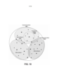
[0030] Seria, assim, desejável fornecer um sistema que alcance ordens de aumento de magnitude na eficiência espectral explorando ganho de multiplexação intercelular através de processamento espacial, através da remoção de qualquer restrição da potência transmitida das BTSs 501 distribuídas, bem como da sua colocação. A Figura 5 mostra um exemplo onde muitos pontos adicionais de acesso 502 são adicionados para deliberadamente aumentar o nível de interferência incoerente em toda a célula 503, que é explorada, na presente invenção, para gerar áreas de interferência coerente em torno dos UEs, produzindo, assim, um ganho de multiplexação intercelular teoricamente ilimitado. Os pontos adicionais de acesso são colocados por acaso onde quer que seja conveniente, e não estão restritos a qualquer planejamento específico de célula, como em sistemas celulares descritos na técnica anterior. Em uma modalidade exemplificativa da invenção, os pontos de acesso ao acaso são pontos de acesso de entrada distribuída e saída distribuída (DIDO), e o ganho de multiplexação intercelular é obtido através de métodos DIDO descritos em [0014 a 0020] e [77 a 78]. Em outra modalidade, os pontos de acesso ao acaso são transceptores de baixa potência, similares aos pontos de acesso Wi-Fi de baixo custo ou células pequenas [30, 47], fornecendo, portanto, menores áreas de cobertura sobrepostas em toda a macrocélula conforme mostrado na Figura 5.[0030] It would therefore be desirable to provide a system that achieves orders of magnitude increase in spectral efficiency by exploiting intercellular multiplexing gain through spatial processing, by removing any restriction on the transmitted power of the distributed
[0031] Observou-se que os métodos intercelulares da técnica anterior [53 a 64] evitam a interferência incoerente ao limitar intencionalmente a potência de transmissão de cada BTS, como na Figura 3, e eliminam a interferência residual intercelular (sobre as áreas de sobreposição entre as células) através de processamento espacial, fornecendo, assim, uma SINR melhorada e um ganho de diversidade intercelular. Observou-se ainda que [89] restringe a colocação de BTS para planejamento de célula enquanto aumenta a potência de transmissão, limitando, assim, a capacidade alcançável devido à interferência de fora-do-conjunto, e como tal, é ainda limitada pela interferência. Por outro lado, a presente invenção explora a interferência incoerente para criar interferência coerente em torno dos UEs, transmitindo-se potência mais elevada a partir de cada BTS colocada ao acaso, melhorando, assim, a qualidade do sinal no UE, que é a condição necessária para obter ganho de multiplexação intercelular em toda a célula através de processamento espacial. Dessa forma, os sistemas descritos na técnica anterior não podem ser usados para alcançar um ganho de multiplexação intercelular ilimitado através de processamento espacial, já que não há suficiente SINR em toda a célula (devido à potência de transmissão limitada das BTSs ou a interferência de fora-do-conjunto, quando a potência de transmissão é aumentada) para habilitar métodos de multiplexação intercelulares como na presente invenção. Além disso, os sistemas descritos na técnica anterior seriam inoperáveis para obter o ganho de multiplexação obtido na presente invenção representado nas Figuras 4 a 5, dado que os sistemas da técnica anterior foram projetados para evitar interferência intercelular dentro das regiões de diversidade mostradas na área sombreada da Figura 1 e das Figuras 3 a 5, ao invés de explorar a interferência intercelular nas regiões de multiplexação para obter multiplexação intercelular como obtido na presente invenção.[0031] It was observed that the intercell methods of the prior art [53 to 64] avoid incoherent interference by intentionally limiting the transmission power of each BTS, as in Figure 3, and eliminate residual intercell interference (over areas of overlap between cells) through spatial processing, thus providing an improved SINR and intercellular diversity gain. It was further noted that [89] restricts the placement of BTS for cell planning while increasing the transmit power, thus limiting the achievable capacity due to out-of-set interference, and as such, is further limited by interference. . On the other hand, the present invention exploits the incoherent interference to create coherent interference around the UEs by transmitting higher power from each randomly placed BTS, thus improving the signal quality in the UE, which is the condition required to obtain intercellular multiplexing gain across the cell through spatial processing. Thus, the systems described in the prior art cannot be used to achieve unlimited intercell multiplexing gain through spatial processing, as there is not enough cell-wide SINR (due to the limited transmit power of the BTSs or interference from outside). -of-the-set, when the transmit power is increased) to enable intercell multiplexing methods as in the present invention. Furthermore, the systems described in the prior art would be inoperable to obtain the multiplexing gain obtained in the present invention represented in Figures 4 to 5, since the prior art systems were designed to avoid intercellular interference within the diversity regions shown in the shaded area of Figure 1 and Figures 3 to 5, instead of exploiting the intercell interference in the multiplexing regions to obtain intercell multiplexing as achieved in the present invention.
[0032] Um melhor entendimento da presente invenção pode ser obtido a partir da seguinte descrição detalhada em conjunto com os desenhos, em que:[0032] A better understanding of the present invention can be obtained from the following detailed description together with the drawings, in which:
[0033] A Figura 1 ilustra a multiplexação e regiões de diversidade para uma macrocélula e uma célula pequena.[0033] Figure 1 illustrates the multiplexing and diversity regions for a macrocell and a small cell.
[0034] A Figura 2a ilustra o padrão de reuso de frequência completo em sistemas celulares convencionais.[0034] Figure 2a illustrates the complete frequency reuse pattern in conventional cellular systems.
[0035] A Figura 2b ilustra o padrão de reuso de frequência intenso (HFR) em sistemas celulares convencionais.[0035] Figure 2b illustrates the intense frequency reuse (HFR) pattern in conventional cellular systems.
[0036] A Figura 2c ilustra o padrão de reuso de frequência fraccionado (FFR) em sistemas celulares convencionais.[0036] Figure 2c illustrates the pattern of fractional frequency reuse (FFR) in conventional cellular systems.
[0037] A Figura 3 ilustra a região de interferência entre macrocélulas adjacentes.[0037] Figure 3 illustrates the interference region between adjacent macrocells.
[0038] A Figura 4 ilustra múltiplas BTSs transmitindo com potência superior para aumentar o nível de interferência entre células.[0038] Figure 4 illustrates multiple BTSs transmitting at higher power to increase the level of interference between cells.
[0039] A Figura 5 ilustra um exemplo onde muitos pontos de acesso são adicionados deliberadamente para aumentar o nível de interferência incoerente em toda a célula.[0039] Figure 5 illustrates an example where too many access points are deliberately added to increase the level of incoherent interference throughout the cell.
[0040] A Figura 6 ilustra os elementos de rede em redes LTE.[0040] Figure 6 illustrates the network elements in LTE networks.
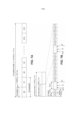
[0041] A Figura 7a ilustra a estrutura de quadro LTE para operação FDD.[0041] Figure 7a illustrates the LTE frame structure for FDD operation.
[0042] A Figura 7b ilustra a estrutura de quadro LTE para operação TDD.[0042] Figure 7b illustrates the LTE frame structure for TDD operation.
[0043] A Figura 8a ilustra os “elementos de recurso” de LTE e “blocos de recurso” no canal OFDM DL.[0043] Figure 8a illustrates the LTE “resource elements” and “resource blocks” in the OFDM DL channel.
[0044] A Figura 8b ilustra os “elementos de recurso” de LTE e os “blocos de recurso” no canal SC-FDMA UL.[0044] Figure 8b illustrates the LTE “feature elements” and the “feature blocks” in the SC-FDMA UL channel.
[0045] A Figura 9 ilustra uma modalidade de um sistema de múltiplas antenas (MAS) para multiusuários (MU), ou MU-MAS, que consiste em conjuntos de antenas e conjuntos de usuários.[0045] Figure 9 illustrates an embodiment of a multi-user (MU) multiple antenna system (MAS), or MU-MAS, consisting of antenna arrays and user arrays.
[0046] A Figura 10 ilustra uma modalidade de um MU-MAS em que uma ID celular diferente está associada a cada subconjunto de antena.[0046] Figure 10 illustrates an embodiment of a MU-MAS in which a different cell ID is associated with each antenna subset.
[0047] A Figura 11 ilustra uma modalidade de um MU-MAS em que o mesmo conjunto de IDs celulares é atribuído aos subconjuntos de antena com um dado padrão de recorrência.[0047] Figure 11 illustrates an embodiment of a MU-MAS in which the same set of cell IDs is assigned to antenna subsets with a given recurrence pattern.
[0048] A Figura 12 ilustra a distribuição de SNR para implantação prática dos sistemas MU-MAS no centro de San Francisco, CA, com áreas esparsamente e densamente povoadas.[0048] Figure 12 illustrates the SNR distribution for practical deployment of MU-MAS systems in downtown San Francisco, CA, with sparsely and densely populated areas.
[0049] A Figura 13 ilustra uma modalidade de um MU-MAS consistindo em CP, BTSs distribuídas e múltiplos UEs.[0049] Figure 13 illustrates an embodiment of a MU-MAS consisting of CP, distributed BTSs and multiple UEs.
[0050] A Figura 14 ilustra uma modalidade de um MU-MAS consistindo em CP, BTSs distribuídas, múltiplos dispositivos e um UE conectado aos dispositivos, bem como às BTSs através de interfaces de rede.[0050] Figure 14 illustrates an embodiment of a MU-MAS consisting of CP, distributed BTSs, multiple devices and a UE connected to the devices as well as to the BTSs through network interfaces.
[0051] A Figura 15 ilustra uma modalidade de um MU-MAS em que o UE está em um caso que se conecta fisicamente ao dispositivo de usuário.[0051] Figure 15 illustrates an embodiment of a MU-MAS in which the UE is in a case that physically connects to the user device.
[0052] Uma solução para superar muitas das limitações da técnica anterior acima é uma modalidade da tecnologia Entrada Distribuída e Saída Distribuída (DIDO). A tecnologia DIDO é descrita nas patentes e nos pedidos de patentes a seguir, sendo que todos são atribuídos ao cessionário da presente patente e estão incorporados a título de referência. Essas patentes e pedidos são, às vezes, referidos coletivamente como “Patentes e Pedidos Relacionados”. Pedido de Patente n° US 13/633.702, intitulado “Systems and Methods for wireless backhaul in distributed-input distributed-output wireless systems” Pedido de Patente n° US 13/475.598, intitulado “Systems and Methods to enhance spatial diversity in distributed-input distributed-output wireless systems” Pedido de Patente n° US 13/233.006, intitulado “System and Methods for planned evolution and obsolescence of multiuser spectrum” Pedido de Patente n° US 13/232.996, intitulado “Systems and Methods to Exploit Areas of Coherence in Wireless Systems” Pedido de Patente n° US 13/464.648, intitulado “System and Methods to Compensate for Doppler Effects in Distributed-Input Distributed Output Systems” Pedido de Patente n° US 12/917.257, intitulado “Systems And Methods To Coordinate Transmissions In Distributed Wireless Systems Via User Clustering” Pedido de Patente n° US 12/802.988, intitulado “Interference Management, Handoff, Power Control And Link Adaptation In Distributed-Input Distributed-Output (DIDO) Communication Systems” Pedido de Patente n° US 12/802.974, intitulado “System And Method For Managing Inter-Cluster Handoff Of Clients Which Traverse Multiple DIDO Clusters” Pedido de Patente n° US 12/802.989, intitulado “System And Method For Managing Handoff Of A Client Between Different Distributed-Input-Distributed- Output (DIDO) Networks Based On Detected Velocity Of The Client” Pedido de Patente n° US 12/802.958, intitulado “System And Method For Power Control And Antenna Grouping In A Distributed-Input-Distributed-Output (DIDO) Network” Pedido de Patente n° US 12/802.975, intitulado “System And Method For Link adaptation In DIDO Multicarrier Systems” Pedido de Patente n° US 12/802.938, intitulado “System And Method For DIDO Precoding Interpolation In Multicarrier Systems” Pedido de Patente n° US 12/630.627, intitulado “System and Method For Distributed Antenna Wireless Communications” Patente n° US 8.170.081, emitida em 1 de maio de 2012, intitulada “System And Method For Adjusting DIDO Interference Cancellation Based On Signal Strength Measurements” Patente n° US 8.160.121, emitida em 17 de abril de 2012, intitulada “System and Method For Distributed Input-Distributed Output Wireless Communications”; Patente n° US 7.885.354, emitida em 8 de fevereiro de 2011, intitulada “System and Method For Enhancing Near Vertical Incidence Skywave (“NVIS”) Communication Using Space-Time Coding”. Patente n° US 7.711.030, emitida em 4 de maio de 2010, intitulada “System and Method For Spatial-Multiplexed Tropospheric Scatter Communications”; Patente n° US 7.636.381, emitida em 22 de dezembro de 2009, intitulada “System and Method for Distributed Input Distributed Output Wireless Communication”; Patente n° US7.633.994, emitida em 15 de dezembro de 2009, intitulada “System and Method for Distributed Input Distributed Output Wireless Communication”; Patente n° US 7.599.420, emitida em 6 de outubro de 2009, intitulada “System and Method for Distributed Input Distributed Output Wireless Communication”; Patente n° US 7.418.053, emitida em 26 de agosto de 2008, intitulada “System and Method for Distributed Input Distributed Output Wireless Communication”;[0052] One solution to overcome many of the above prior art limitations is a Distributed Input Distributed Output (DIDO) technology modality. The DIDO technology is described in the following patents and patent applications, all of which are assigned to the assignee of this patent and are incorporated by reference. These patents and applications are sometimes collectively referred to as “Patents and Related Applications”. Patent Application No. US 13/633,702, entitled “Systems and Methods for wireless backhaul in distributed-input distributed-output wireless systems” Patent Application No. US 13/475,598, entitled “Systems and Methods to enhance spatial diversity in distributed- input distributed-output wireless systems” Patent Application No. US 13/233,006, entitled “System and Methods for planned evolution and obsolescence of multiuser spectrum” Patent Application No. US 13/232,996, entitled “Systems and Methods to Exploit Areas of Coherence in Wireless Systems” US Patent Application No. 13/464,648, entitled “System and Methods to Compensate for Doppler Effects in Distributed-Input Distributed Output Systems” US Patent Application No. 12/917,257, entitled “Systems And Methods To Coordinate Transmissions In Distributed Wireless Systems Via User Clustering” US Patent Application 12/802,988 entitled “Interference Management, Handoff, Power Control And Link Adaptation In Distributed-Input Distributed-Output (DIDO) Communication Systems” US Patent Application 12/802,974, entitled “System And Method For Managing Inter-Cluster Handoff Of Clients Which Traverse Multiple DIDO Clusters” Patent Application No. US 12/802,989, entitled “System And Method For Managing Handoff Of A Client Between Different Distributed-Input- Distributed-Output (DIDO) Networks Based On Detected Velocity Of The Client” Patent Application No. US 12/802,958, entitled “System And Method For Power Control And Antenna Grouping In A Distributed-Input-Distributed-Output (DIDO) Network” Patent Application No. US 12/802,975, entitled “System And Method For Link Adaptation In DIDO Multicarrier Systems” US Patent No. 12/630,627, entitled “System and Method For Distributed Antenna Wireless Communications” US Patent No. 8,170,081, issued May 1, 2012, entitled “System And Method For Adjusting DIDO Interference Cancellation Based On Signal Strength Measurements” Patent No. US 8,160,121, issued April 17, 2012, entitled “System and Method For Distributed Input-Distributed Output Wireless Communications”; US Patent No. 7,885,354, issued February 8, 2011, entitled “System and Method For Enhancing Near Vertical Incidence Skywave (“NVIS”) Communication Using Space-Time Coding”. US Patent No. 7,711,030, issued May 4, 2010, entitled “System and Method For Spatial-Multiplexed Tropospheric Scatter Communications”; US Patent No. 7,636,381, issued December 22, 2009, entitled “System and Method for Distributed Input Distributed Output Wireless Communication”; Patent No. US7,633,994, issued on December 15, 2009, entitled “System and Method for Distributed Input Distributed Output Wireless Communication”; US Patent No. 7,599,420, issued October 6, 2009, entitled “System and Method for Distributed Input Distributed Output Wireless Communication”; US Patent No. 7,418,053, issued August 26, 2008, entitled “System and Method for Distributed Input Distributed Output Wireless Communication”;
[0053] Para reduzir o tamanho e a complexidade do presente pedido de patente, a divulgação de algumas das patentes e pedidos de patente relacionados não é explicitamente descrita abaixo. Favor consultar as Patentes e Pedidos Relacionados para uma descrição completa da revelação.[0053] To reduce the size and complexity of the present patent application, the disclosure of some of the patents and related patent applications is not explicitly described below. Please see Related Patents and Applications for a full description of the disclosure.
[0054] A presente invenção descreve um sistema e métodos para explorar o ganho de multiplexação intercelular em redes de comunicação sem fio através de processamento espacial, empregando um sistema de múltiplas antenas (MAS) com transmissões multiusuário (MU) (um sistema de múltiplas antenas multiusuário, ou “MU-MAS”), onde as múltiplas antenas são colocadas ao acaso. Em uma modalidade da invenção, a potência transmitida a partir das múltiplas antenas é limitada para minimizar a interferência nos limites das células (como em sistemas celulares convencionais) e os métodos de processamento espacial são utilizados apenas para eliminar a interferência entre as células. Em outra modalidade da invenção, a potência transmitida de múltiplas antenas não é restrita a qualquer nível específico de potência (desde que seu nível de emissão de potência se enquadre nos limites de regulamentação, segurança ou práticos (por exemplo, potência disponível, especificações do transmissor e/ou antena), criando, assim, intencionalmente, níveis mais elevados de interferência intercelular em toda a célula que é explorada para atingir um ganho de multiplexação intercelular, e aumentam a capacidade da rede de comunicações sem fio.[0054] The present invention describes a system and methods for exploiting intercell multiplexing gain in wireless communication networks through spatial processing, employing a multiple antenna system (MAS) with multiuser (MU) transmissions (a multiple antenna system multi-user, or “MU-MAS”), where multiple antennas are randomly placed. In one embodiment of the invention, the transmitted power from the multiple antennas is limited to minimize interference at cell boundaries (as in conventional cellular systems) and the spatial processing methods are used only to eliminate interference between cells. In another embodiment of the invention, the transmitted power from multiple antennas is not restricted to any specific power level (as long as their power output level falls within regulatory, safety, or practical limits (e.g., available power, transmitter specifications and/or antenna), thereby intentionally creating higher levels of intercell interference throughout the cell which is exploited to achieve an intercell multiplexing gain, and increase the capacity of the wireless communications network.
[0055] Em uma modalidade, a rede de comunicações sem fio é uma rede celular, como nas Figuras 1 e 3, como uma rede celular baseada em padrões de LTE e as múltiplas antenas implantadas ao acaso são transceptores para macrocélulas ou células pequenas. Em outra modalidade da invenção, a rede de comunicações sem fio não é limitada a qualquer disposição de célula particular, e os limites da célula podem se estender ao longo de áreas maiores, como nas Figuras 4 a 5. Por exemplo, a rede de comunicações sem fio poderia ser uma rede de área local sem fio (WLAN) com múltiplas antenas sendo pontos de acesso Wi-Fi, ou uma malha, rede de propósito específico ou de sensor, ou um sistema de antena distribuída, ou um sistema DIDO com pontos de acesso colocados ao acaso sem qualquer restrição da potência de transmissão. Porém, como exemplo, as estruturas de rede não devem ser consideradas como limitadoras da aplicabilidade geral da presente invenção às redes de comunicações sem fios. A presente invenção aplica-se a qualquer rede sem fios, onde o ganho de multiplexação é conseguido através de sinais de transmissão a partir de múltiplas antenas que interferem onde recebidas por vários UEs, de modo a criar fluxos de dados não interferentes simultaneamente para vários UEs.[0055] In one embodiment, the wireless communications network is a cellular network, as in Figures 1 and 3, as a cellular network based on LTE standards, and the randomly deployed multiple antennas are transceivers for macrocells or small cells. In another embodiment of the invention, the wireless communications network is not limited to any particular cell arrangement, and the cell boundaries may extend over larger areas, as in Figures 4 to 5. For example, the communications network wireless could be a wireless local area network (WLAN) with multiple antennas being Wi-Fi access points, or a mesh, special purpose or sensor network, or a distributed antenna system, or a DIDO system with points access points placed at random without any restriction on transmission power. However, as an example, network structures should not be considered as limiting the general applicability of the present invention to wireless communication networks. The present invention applies to any wireless network, where multiplexing gain is achieved by transmitting signals from multiple antennas that interfere where received by multiple UEs, so as to create non-interfering data streams simultaneously for multiple UEs. .
[0056] O MU-MAS consiste em um processador centralizado, uma rede e M estações transceptores (ou antenas distribuídas) se comunicando sem fio com N dispositivos de cliente ou UEs. A unidade de processador centralizado recebe N fluxos de informação com diferentes conteúdos de rede (por exemplo, vídeos, páginas da web, videogames, texto, voz, etc., transmitidos de servidores da web ou outras fontes de rede) destinados a diferentes dispositivos de cliente. A seguir, usou-se o termo “fluxo de informações” para se referir a qualquer fluxo de dados enviado pela rede contendo informações que possam ser demoduladas ou decodificadas como um fluxo autônomo, de acordo com certo esquema de modulação/codificação ou protocolo, para produzir todos os dados, incluindo, mas não se limitando a áudio, web e conteúdo de vídeo. Em uma modalidade, o fluxo de informação é uma sequência de bits que transporta conteúdos de rede que podem ser demodulados ou decodificados como uma corrente independente.[0056] The MU-MAS consists of a centralized processor, a network and M transceiver stations (or distributed antennas) communicating wirelessly with N client devices or UEs. The centralized processor unit receives N streams of information with different network contents (e.g. videos, web pages, video games, text, voice, etc., transmitted from web servers or other network sources) destined for different client. In the following, the term “information stream” is used to refer to any stream of data sent over the network containing information that can be demodulated or decoded as a standalone stream, according to a certain modulation/coding scheme or protocol, to produce all data including but not limited to audio, web and video content. In one embodiment, the information stream is a bit stream carrying network contents that can be demodulated or decoded as an independent stream.
[0057] O processador centralizado utiliza transformação de pré-codificação para combinar (de acordo com algoritmos, tais como os descritos nas patentes e pedidos de patentes relacionados) os N fluxos de informações de conteúdo da rede em M fluxos de bits. A título de exemplo, mas não como limitação, a transformação de precodificação pode ser linear (por exemplo, força-zero, [65], diagonalização de bloco [66 a 67], inversão de matriz, etc.) ou não linear (por exemplo, codificação de papel sujo [68 a 70], ou precodificação de Tomlinson-Harashima [71 a 72], técnicas de treliça ou precodificação de treliça [73 a 74], técnicas de perturbação de vetor [75 a 76]). A partir de agora, é usado o termo “fluxo de bits” para se referir a qualquer sequência de bits que não necessariamente contém qualquer bit de informação útil e, como tal, não pode ser demodulada ou decodificada como um fluxo autônomo para recuperar o conteúdo da rede. Em uma modalidade da invenção, a corrente de bits é o sinal de banda base complexo produzido pelo processador centralizado e quantificado sobre determinado número de bits a ser enviado para uma das M estações transceptoras.[0057] The centralized processor uses precoding transformation to combine (according to algorithms such as those described in related patents and patent applications) the N streams of network content information into M streams of bits. By way of example, but not limitation, the precoding transform can be linear (eg zero-force, [65], block diagonalization [66 to 67], matrix inversion, etc.) or non-linear (eg dirty paper coding [68 to 70], or Tomlinson-Harashima precoding [71 to 72], trellis techniques or trellis precoding [73 to 74], vector perturbation techniques [75 to 76]). Hereafter, the term “bitstream” is used to refer to any sequence of bits that does not necessarily contain any bits of useful information and, as such, cannot be demodulated or decoded as a standalone stream to retrieve the contents. from the Web. In one embodiment of the invention, the bitstream is the complex baseband signal produced by the centralized processor and quantized over a given number of bits to be sent to one of the M transceiver stations.
[0058] A pré-codificação é calculada no processador centralizado ao empregar as informações de estado do canal (CSI) e aplicada sobre os canais de DL ou UL para multiplexar fluxos de dados de multiplex para ou de múltiplos usuários. Em uma modalidade da invenção, o processador centralizado está ciente das CSI entre as antenas distribuídas e os dispositivos de cliente, e utiliza as CSI para pré-codificar dados enviados através dos canais de DL ou UL. Na mesma modalidade, as CSI são estimadas nos dispositivos de cliente e enviadas para as antenas distribuídas. Em outra modalidade, as DL-CSI são derivadas nas antenas distribuídas a partir das UL-CSI usando calibração por rádio frequência (RF) e explorando a reciprocidade de canal de UL/DL.[0058] The precoding is calculated in the centralized processor using the channel state information (CSI) and applied over the DL or UL channels to multiplex multiplex data streams to or from multiple users. In one embodiment of the invention, the centralized processor is aware of the CSI between the distributed antennas and the client devices, and uses the CSI to pre-encode data sent over the DL or UL channels. In the same way, the CSI are estimated in the client devices and sent to the distributed antennas. In another embodiment, the DL-CSI are derived on distributed antennas from the UL-CSI using radio frequency (RF) calibration and exploiting UL/DL channel reciprocity.
[0059] Em uma modalidade, o MU-MAS é um sistema de entrada distribuída e saída distribuída (DIDO) conforme descrito nas patentes e pedidos de patentes relacionados. Em outra modalidade, o MU-MAS representado na Figura 13 consiste em: • Equipamento de Usuário (UE) 1301: Um transceptor de RF para clientes fixos e/ou móveis que recebe fluxos de dados através do canal de enlace descendente (DL) a partir do retorno e que transmite dados para o backhaul através do canal de enlace ascendente (UL) • Estação Transceptora Base (BTS) 1302: As BTSs fazem a interface do backhaul com o canal sem fio. As BTSs de uma modalidade são pontos de acesso que consistem em uma cadeia de Conversor Digital-para-Analógico (DAC) / Analógico-para-Digital (ADC) e rádio frequência (RF) para converter o sinal da banda de base para RF. Em alguns casos, a BTS é um transceptor de RF simples equipado com amplificador de potência/antena, e o sinal de RF é transportado para a BTS através da tecnologia RF-sobre-fibra, conforme descrito nas Patentes e Pedidos Relacionados. • Controlador (CTR) 1303: Um CT é um tipo particular de BTS designado para certas características especializadas, tais como a transmissão de sinais de treinamento para sincronização de tempo/frequência das BTSs e/ou dos UEs, receber/transmitir informações de controle de/para os UEs, receber as informações de estado de canal (CSI) ou informações de qualidade de canal dos UEs. Uma ou múltiplas estações de CTR podem ser incluídas em qualquer sistema MU-MAS. Quando vários CTRs estão disponíveis, as informações para ou a partir dessas estações podem ser combinadas para aumentar a diversidade e melhorar a qualidade do enlace. Em uma modalidade, as CSI são recebidas a partir de vários CTR através de técnicas de combinação da razão máxima (MRC) para melhorar a demodulação das CSI. Em outra modalidade, as informações de controle são enviadas a partir de múltiplos CTRs através de transmissão de razão máxima (MRT) para melhorar a SNR no lado do receptor. O escopo da invenção não se limita a MRC ou MRT, e qualquer outra técnica de diversidade (tal como a seleção de antena, etc.) pode ser empregada para melhorar os enlaces remotos entre CTRs e UEs. • Processador Centralizado (CP) 1304: O CP é um servidor que realiza a interface da Internet ou outros tipos de redes externas 1306 com o backhaul. Em uma modalidade, o CP calcula o processamento de base da banda de MU-MAS e envia as formas de onda para as BTSs distribuídas para transmissão por DL • Rede de Estação Base (BSN) 1305: A BSN é a rede que liga o CP às BTSs distribuídas transportando informações tanto para o canal de DL quanto de UL. A BSN é uma rede fixa ou uma rede sem fios ou uma combinação das duas. Por exemplo, a BSN é um DSL, cabo, rede de fibra ótica, ou enlace remoto de Linha-de- Vista (LOS) ou Não-Linha-de-Vista (NLOS). Além disso, a BSN é uma rede comum, ou uma rede de área local, ou a Internet.[0059] In one embodiment, the MU-MAS is a distributed input, distributed output (DIDO) system as described in related patents and patent applications. In another embodiment, the MU-MAS depicted in Figure 13 consists of: • User Equipment (UE) 1301: An RF transceiver for fixed and/or mobile customers that receives data streams through the downlink (DL) channel from from the return and that transmits data to the backhaul over the uplink (UL) channel • Base Transceiver Station (BTS) 1302: The BTSs interface the backhaul to the wireless channel. One-mode BTSs are access points consisting of a Digital-to-Analog Converter (DAC) / Analog-to-Digital (ADC) and radio frequency (RF) chain to convert the baseband signal to RF. In some cases, the BTS is a simple RF transceiver equipped with a power amplifier/antenna, and the RF signal is carried to the BTS via RF-over-fiber technology as described in Related Patents and Applications. • Controller (CTR) 1303: A CT is a particular type of BTS designed for certain specialized features, such as transmitting training signals for time/frequency synchronization of BTSs and/or UEs, receiving/transmitting control information from /for the UEs, receive the channel state information (CSI) or channel quality information from the UEs. One or multiple CTR stations can be included in any MU-MAS system. When multiple CTRs are available, information to or from these stations can be combined to increase diversity and improve link quality. In one embodiment, CSIs are received from multiple CTRs using maximum ratio combining (MRC) techniques to improve CSI demodulation. In another embodiment, control information is sent from multiple CTRs via maximum rate transmission (MRT) to improve the SNR on the receiver side. The scope of the invention is not limited to MRC or MRT, and any other diversity technique (such as antenna selection, etc.) can be employed to improve remote links between CTRs and UEs. • Centralized Processor (CP) 1304: The CP is a server that performs the interface to the Internet or other types of
[0060] Daqui em diante é descrito como a estrutura de MU-MAS acima é incorporada no padrão de LTE para sistemas celulares (e também sistemas não celulares utilizando protocolos de LTE) para obter ganhos adicionais na eficiência espectral. Começa-se com uma visão geral da estrutura de LTE e técnicas de modulação empregadas nos canais de DL e UL. Em seguida, é fornecida uma breve descrição da estrutura de quadro da camada física e alocação de recursos no padrão de LTE. Finalmente, são definidos métodos de pré-codificação de MU-MAS para canais de enlace descendente (DL) e ascendente (UL) em cenários multiusuários usando a estrutura de LTE. Para os esquemas de DL, são propostas duas soluções: esquemas de DIDO de circuito aberto e circuito fechado.[0060] Hereinafter it is described how the above MU-MAS structure is incorporated into the LTE standard for cellular systems (and also non-cellular systems utilizing LTE protocols) to obtain further gains in spectral efficiency. It starts with an overview of the LTE structure and modulation techniques employed on the DL and UL channels. Next, a brief description of the physical layer frame structure and resource allocation in the LTE standard is provided. Finally, MU-MAS precoding methods are defined for downlink (DL) and uplink (UL) channels in multiuser scenarios using the LTE framework. For DL schemes, two solutions are proposed: open-loop and closed-loop DIDO schemes.
[0061] A LTE é projetada com uma arquitetura de rede plana (em oposição a uma arquitetura hierárquica de padrões celulares anteriores) para fornecer: latência reduzida, perdas de pacote reduzidas através de ARQ, tempo de configuração de chamada reduzido, cobertura e taxa de transferência melhoradas através de macrodiversidade. Os elementos de rede em redes de LTE representados na Figura 6 são por [79]: • GW (gateway): é o roteador que conecta a rede de LTE a redes externas (ou seja, a Internet). O GW é dividido em gateway de serviço (S-GW) 601, que finaliza a interface E-UTRAN 608, e gateway PDN (P-GW) 602, que é a interface dotada de redes externas. Os S-GW e P-GW são parte do chamado núcleo de pacote evoluído (EPC) 609; • MME (entidade de gestão de mobilidade) 603: gerencia a mobilidade, parâmetros de segurança e identidade do UE. A MME é também parte da LTE EPC; • eNodeB (Nó-B melhorado) 604: é a estação de base que trata do gerenciamento de recursos de rádio, mobilidade de usuário e agendamento; • UE (equipamento de usuário) 605: é a estação móvel. • Interfaces S1 e X2 (606 e 607): são os backhauls de rede fixa ou sem fio entre a MME e eNodeBs (S1-MME), o S-GW e eNodeBs (S1-U) e entre vários eNodeBs (X2).[0061] LTE is designed with a flat network architecture (as opposed to a hierarchical architecture of previous cellular standards) to provide: reduced latency, reduced packet losses through ARQ, reduced call setup time, reduced coverage and improved transfer through macrodiversity. The network elements in LTE networks represented in Figure 6 are by [79]: • GW (gateway): is the router that connects the LTE network to external networks (ie, the Internet). The GW is divided into service gateway (S-GW) 601, which ends the
[0062] Em uma modalidade da invenção, a rede MU-MAS é uma rede de LTE em que o UE é o UE de LTE, a BTS é o LTE eNodeB, o CTR é o LTE eNodeB ou MME, o CP é o LTE GW, o BSN é a interface S1 ou X1. Daqui por diante são usados os termos antenas distribuídas, BTS e eNodeB indistintamente para se referir a qualquer estação base em sistemas MU-MAS, DIDO ou LTE.[0062] In one embodiment of the invention, the MU-MAS network is an LTE network in which the UE is the LTE UE, the BTS is the LTE eNodeB, the CTR is the LTE eNodeB or MME, the CP is the LTE GW, the BSN is the S1 or X1 interface. Hereafter the terms distributed antennas, BTS and eNodeB are used interchangeably to refer to any base station in MU-MAS, DIDO or LTE systems.
[0063] O quadro de LTE tem duração de 10 ms e consiste em dez subquadros, conforme representado na Figura 7 [33, 80]. Cada subquadro é dividido em duas partições de 0,5 ms de duração cada. Os padrões de LTE definem dois tipos de quadros: i) tipo 1 para operação FDD, como na Figura 7a), onde todos os subquadros são atribuídos aos canais de DL ou UL; ii) tipo 2 para operação TDD, como na Figura 7b), onde, parte dos subquadros são atribuídos ao DL e parte ao UL (dependendo da configuração selecionada), enquanto que alguns subquadros são reservados para “uso especial”. Existe pelo menos um subquadro especial por quadro, e o mesmo consiste em três campos: i) espaço de tempo piloto de enlace descendente (DwPTS), reservado para transmissão de DL; ii) período de guarda (GP); iii) espaço de tempo piloto de enlace ascendente (UpPTS), para a transmissão de UL.[0063] The LTE frame lasts 10 ms and consists of ten subframes, as shown in Figure 7 [33, 80]. Each subframe is divided into two partitions of 0.5 ms duration each. LTE standards define two types of frames: i)
[0064] A LTE emprega multiplexação de divisão de frequência ortogonal (OFDM) e modulação de acesso múltiplo de divisão de frequência ortogonal (OFDMA) para o DL e acesso múltiplo de divisão de frequência portadora única (SC-FDMA) para o UL. O “elemento de recurso” (RE) é a menor estrutura de modulação em LTE e consiste em uma subportadora de OFDM em frequência e uma duração de símbolo de OFDM no tempo, como mostrado na Figura 8a para o canal de DL e na Figura 8b para o canal de UL. O “bloco de recursos” (RB) é composto por 12 subportadoras na frequência e um intervalo de 0,5 ms no tempo (que consiste em 3 a 7 períodos de símbolo de OFDM, dependendo do canal de DL contra UL e tipo de prefixo cíclico). Os blocos de recursos para cada UE são atribuídos em uma base de subquadro. Já que o MU-MAS, na presente invenção, usa processamento espacial para enviar múltiplos fluxos de dados para diferentes UEs, em cada subquadro, todos os blocos de recursos podem ser alocados para o mesmo UE. Em uma aplicação, todos ou um subconjunto de blocos de recursos é alocado para cada UE, e transmissões de dados sem interferência simultânea são enviadas para os UEs através de pré-codificação.[0064] LTE employs orthogonal frequency division multiplexing (OFDM) and orthogonal frequency division multiple access modulation (OFDMA) for the DL and single carrier frequency division multiple access (SC-FDMA) for the UL. The “resource element” (RE) is the smallest modulation structure in LTE and consists of an OFDM subcarrier in frequency and an OFDM symbol duration in time, as shown in Figure 8a for the DL channel and in Figure 8b for the UL channel. The “resource block” (RB) is composed of 12 subcarriers in frequency and a 0.5ms gap in time (which consists of 3 to 7 OFDM symbol periods, depending on the DL versus UL channel and prefix type cyclic). Resource blocks for each UE are allocated on a subframe basis. Since the MU-MAS, in the present invention, uses spatial processing to send multiple data streams to different UEs, in each subframe, all resource blocks can be allocated to the same UE. In an application, all or a subset of resource blocks are allocated to each UE, and simultaneous interference-free data streams are sent to the UEs through precoding.
[0065] Para configurar a ligação entre a BTS e os UEs, o padrão de LTE define o procedimento de sincronização. A BTS envia dois sinais consecutivos para o UE: o sinal primário de sincronização (P-SS), enviado pelo canal primário de sincronização (PSCH), e o sinal secundário de sincronização (S-SS), enviado pelo canal secundário de sincronização (SSCH). Ambos os sinais são usados pelo UE para sincronização de tempo/frequência, bem como para recuperar o ID da célula. O P-SS consiste em sequência Zadoff-Chu de comprimento-63 da qual o UE deriva o ID da camada física (0 a 2). O S-SS é uma concatenação intercalada de duas sequências binárias de comprimento-31, e é usado para derivar o número de grupo de IDs celulares (0 a 167). Dos dois números de identidade acima, o UE deriva o ID celular físico (PCI, definido a partir de 0 até 503).[0065] To configure the connection between the BTS and the UEs, the LTE standard defines the synchronization procedure. The BTS sends two consecutive signals to the UE: the primary synchronization signal (P-SS), sent on the primary synchronization channel (PSCH), and the secondary synchronization signal (S-SS), sent on the secondary synchronization channel ( SSCH). Both signals are used by the UE for time/frequency synchronization as well as for retrieving the cell ID. The P-SS consists of Zadoff-Chu sequence of length-63 from which the UE derives the physical layer ID (0 to 2). The S-SS is an interleaved concatenation of two binary sequences of length-31, and is used to derive the group number of cell IDs (0 to 167). From the above two identity numbers, the UE derives the Physical Cell ID (PCI, defined from 0 to 503).
[0066] No sistema MU-MAS descrito na presente invenção, não existem limites de células conforme a potência transmitida a partir das BTSs é aumentada intencionalmente para produzir interferência, a qual é explorada para criar áreas de coerência em torno dos UEs. Na presente invenção, diferentes BTSs são agrupadas em “conjuntos de antenas” ou “conjuntos DIDO”, conforme definido na Patente no US 8.170.081, emitida em 1 de maio de 2012, intitulada “System And Method For Adjusting DIDO Interference Cancellation Based On Signal Strength Measurements”. Por exemplo, a Figura 9 mostra o principal conjunto de antena 901 e um conjunto de antena adjacente 902. Cada conjunto de antena consiste em várias BTSs 903.[0066] In the MU-MAS system described in the present invention, there are no cell boundaries as the transmitted power from the BTSs is intentionally increased to produce interference, which is exploited to create areas of coherence around the UEs. In the present invention, different BTSs are grouped into “antenna sets” or “DIDO sets”, as defined in Patent No. US 8,170,081, issued on May 1, 2012, entitled “System And Method For Adjusting DIDO Interference Cancellation Based On Signal Strength Measurements”. For example, Figure 9 shows the
[0067] O ID da célula pode ser usado em sistemas MU-MAS e DIDO para diferenciar os conjuntos de antena. Em uma modalidade da invenção, o mesmo ID celular é transmitido a partir de todas BTSs do mesmo conjunto de antena por meio de P-SS e S-SS. Na mesma modalidade, diferentes conjuntos de antena empregam diferente IDs celulares. Em outra modalidade da invenção, todas as BTSs dentro do mesmo conjunto de antena 1001 são agrupadas em “subconjuntos de antena” 1003, representados na Figura 10 com cores sombreadas diferentes, e um ID celular diferente 1004 é associado a cada subconjunto de antena. Em uma modalidade, os subconjuntos de antena são definidos estaticamente de acordo com o planejamento predefinido de conjunto ou com base em informações de posicionamento por GPS. Em outra modalidade, os subconjuntos de antena são definidos dinamicamente com base em medições de intensidade relativa de sinal entre BTSs ou informações de posicionamento por GPS. Em uma modalidade diferente da invenção, um ID celular diferente é atribuído a cada área de coerência (descrito no Pedido de Patente dos EUA copendente n° 13/232.996, intitulado “Systems and Methods to Exploit Areas of Coherence in Wireless Systems”) associado aos UEs.[0067] The cell ID can be used in MU-MAS and DIDO systems to differentiate antenna arrays. In one embodiment of the invention, the same cell ID is transmitted from all BTSs of the same antenna array via P-SS and S-SS. In the same embodiment, different antenna arrays employ different cell IDs. In another embodiment of the invention, all BTSs within the
[0068] Quando todas as BTSs dentro do mesmo conjunto de antena ou subconjunto de antena transmitem os anais de transmissão de LTE (por exemplo, P- SS e SS-S) para os UEs, a interferência destrutiva pode degradar o desempenho de sincronização de tempo ou frequência habilitado pelo canal de transmissão. A interferência destrutiva pode ser causada por multicaminhos gerados a partir de BTSs espacialmente distribuídas que recombinam-se incoerentemente em alguns locais do UE. Para evitar ou atenuar este efeito, em uma modalidade da invenção, apenas uma BTS dentre todas as BTSs dentro do mesmo conjunto de antena ou subconjunto de antena transmite os canais de transmissão de LTE (por exemplo, P- SS e SS-S) para todos os UEs. Na mesma modalidade, a BTS que transmite os canais de transmissão de LTE é selecionada para maximizar a potência recebida nos UEs pelos canais de transmissão. Em outra modalidade, apenas um conjunto limitado de BTSs é selecionado para transmitir simultaneamente os canais de transmissão de LTE para todos UEs, de modo que a interferência destrutiva seja evitada no UE. Em uma modalidade diferente da invenção, os canais de transmissão de LTE são enviados com potência superior à carga para alcançar todos os UEs dentro do mesmo conjunto de antena ou subconjunto de antena.[0068] When all BTSs within the same antenna set or antenna subset transmit the LTE transmission channels (for example, P-SS and SS-S) to the UEs, destructive interference can degrade the synchronization performance of time or frequency enabled by the transmission channel. Destructive interference can be caused by multipath generated from spatially distributed BTSs that recombine incoherently at some locations in the UE. To avoid or mitigate this effect, in one embodiment of the invention, only one BTS out of all the BTSs within the same antenna set or antenna subset transmits the LTE transmission channels (e.g. P-SS and SS-S) to all UEs. In the same embodiment, the BTS transmitting the LTE transmission channels is selected to maximize the power received at the UEs by the transmission channels. In another embodiment, only a limited set of BTSs are selected to simultaneously transmit the LTE transmission channels to all UEs, so that destructive interference is avoided in the UE. In a different embodiment of the invention, the LTE transmission channels are sent with power higher than the load to reach all UEs within the same antenna set or antenna subset.
[0069] Conforme descrito acima, a LTE-Avançada suporta esquemas de agregação (CA) de operadora para aumentar a taxa de dados pelo canal de DL. Em MU-MASs, a CA pode ser usada em combinação com pré-codificação para aumentar a taxa de dados por usuário. Em uma modalidade da presente invenção, a pré-codificação de transmissão é aplicada a diferentes porções do espectro de RF (CA interbanda) ou diferentes bandas dentro da mesma porção de espectro (CA de intrabanda) para aumentar a taxa de dados por usuário. Quando empregar CA interbanda, a perda de caminho em diferentes bandas pode alterar-se significativamente conforme essas bandas são centradas em diferentes frequências portadoras. Em sistemas celulares convencionais de LTE, as bandas de frequência em frequências portadoras mais baixas podem experimentar menor perda de caminho do que frequências portadoras mais elevadas. Portanto, aplicar a CA de interbanda em sistemas celulares pode causar interferência intercelular indesejada em frequências portadoras mais baixas. Em contrapartida, o MU-MAS na presente invenção não é limitado pela interferência no limite da célula conforme as BTSs são distribuídas, e não existe qualquer conceito de célula. Essa disposição mais flexível de sistema permite diferentes métodos para CA de interbanda em MU-MAS. Em uma aplicação da presente invenção, o MU-MAS permite CA de interbanda ao empregar um conjunto de BTSs para operar em frequências portadoras mais baixas e um outro conjunto de BTSs para operar em frequências portadoras mais altas, de modo que os dois conjuntos se cruzem ou um conjunto seja o subconjunto do outro. Em outra modalidade, o MU-MAS com pré-codificação emprega métodos de CA em conjunto com padrões de salto de frequência para melhorar a robustez contra atenuação seletiva de frequência ou interferência.[0069] As described above, LTE-Advanced supports carrier aggregation (CA) schemes to increase the data rate over the DL channel. In MU-MASs, CA can be used in combination with precoding to increase the per-user data rate. In one embodiment of the present invention, transmission precoding is applied to different portions of the RF spectrum (inter-band AC) or different bands within the same portion of the spectrum (in-band AC) to increase the data rate per user. When employing interband AC, the path loss on different bands can change significantly as those bands are centered on different carrier frequencies. In conventional LTE cellular systems, frequency bands at lower carrier frequencies may experience less path loss than higher carrier frequencies. Therefore, applying interband AC in cellular systems can cause unwanted intercellular interference at lower carrier frequencies. In contrast, the MU-MAS in the present invention is not limited by interference at the cell boundary as the BTSs are distributed, and there is no cell concept. This more flexible system arrangement allows for different methods for interband CA on MU-MAS. In one application of the present invention, the MU-MAS allows interband CA by employing one set of BTSs to operate at lower carrier frequencies and another set of BTSs to operate at higher carrier frequencies, such that the two sets intersect. or one set is the subset of the other. In another embodiment, precoding MU-MAS employs AC methods in conjunction with frequency hopping patterns to improve robustness against frequency selective attenuation or interference.
[0070] Os esquemas de circuito fechado de MU-MAS podem ser usados em sistemas de duplexação de divisão de tempo (TDD) ou duplexação de divisão de frequência (FDD). Nos sistemas FDD, os canais de DL e UL funcionam em diferentes frequências e, portanto, as informações do estado do canal de DL (CSI) deve ser estimada no lado do UE e relatada de volta para o CP através das BTSs ou CRTs através do canal de UL. Em sistemas TDD, os canais de DL e UL são definidos na mesma frequência, e o sistema pode empregar tanto técnicas de circuito fechado ou esquemas de circuito aberto que exploram a reciprocidade do canal (conforme descrito na seção a seguir). A principal desvantagem dos esquemas de ciclo fechado é que requerem retroalimentação, resultando em maior sobrecarga para informações de controle através do UL. O mecanismo geral para esquemas de circuito fechado em MU-MASs é descrito da seguinte forma: i) as BTSs enviam informações de sinalização para os UEs pelo DL; ii) os UEs exploram essas informações de sinalização para estimar o DL CSI de todas as “BTSs ativas;” iii) os UEs quantizam o DL CSI ou usam livros de códigos para selecionar os pesos de pré-codificação a serem usados para a próxima transmissão; iv) os UEs enviam o CSI quantizado ou o índice do livro de códigos para as BTSs ou CTRs através do canal de UL; v) as BTSs ou CTRs reportam as informações de CSI ou o índice do livro de códigos ao CP, que calcula os pesos de pré-codificação para transmissão de dados pelo DL. As “BTSs ativas” são definidas como o conjunto de BTSs que é atingido por dado UE. Por exemplo, no Pedido de Patente copendente n° US 12/802.974, intitulado “System And Method For Managing Inter-Cluster Handoff Of Clients Which Traverse Multiple DIDO Clusters” e no Pedido de Patente copendente n° US 12/917.257, intitulado “Systems And Methods To Coordinate Transmissions In Distributed Wireless Systems Via User Clustering” definiu-se o “conjunto de usuários” 905 como o conjunto de BTSs que são alcançadas por um dado UE, conforme descrito na Figura 9. O número de BTSs ativas é limitado a um conjunto de usuários de modo a reduzir a quantidade de CSI a ser estimada a partir de BTSs para dado UE, reduzindo, assim, a sobrecarga de retroalimentação pelo UL e a complexidade do cálculo de pré-codificação de MU-MAS no CP.[0070] MU-MAS closed loop schemes can be used in time division duplexing (TDD) or frequency division duplexing (FDD) systems. In FDD systems, the DL and UL channels operate on different frequencies and therefore the DL channel state (CSI) information must be estimated on the UE side and reported back to the CP via the BTSs or CRTs via the UL channel. In TDD systems, the DL and UL channels are set to the same frequency, and the system can employ either closed-loop techniques or open-loop schemes that exploit channel reciprocity (as described in the following section). The main disadvantage of closed-loop schemes is that they require feedback, resulting in greater overhead for control information through the UL. The general mechanism for closed-loop schemes in MU-MASs is described as follows: i) BTSs send signaling information to UEs over DL; ii) UEs exploit this signaling information to estimate the DL CSI of all “active BTSs;” iii) the UEs quantize the DL CSI or use codebooks to select the precoding weights to be used for the next transmission; iv) the UEs send the quantized CSI or the codebook index to the BTSs or CTRs through the UL channel; v) the BTSs or CTRs report the CSI information or the codebook index to the CP, which calculates the precoding weights for data transmission over the DL. “Active BTSs” are defined as the set of BTSs that are reached by a given UE. For example, in Copending Patent Application No. US 12/802,974, entitled “System And Method For Managing Inter-Cluster Handoff Of Clients Which Traverse Multiple DIDO Clusters” and Copending Patent Application No. US 12/917,257, Entitled “Systems And Methods To Coordinate Transmissions In Distributed Wireless Systems Via User Clustering”, the “set of users” 905 was defined as the set of BTSs that are reached by a given UE, as described in Figure 9. The number of active BTSs is limited to a set of users in order to reduce the amount of CSI to be estimated from the BTSs for a given UE, thus reducing the feedback overhead by the UL and the complexity of the MU-MAS precoding calculation in the CP.
[0071] Conforme descrito no parágrafo [0083], a pré-codificação de MU-MAS emprega métodos lineares ou não lineares. No caso de métodos não lineares (por exemplo, codificação bruta [68 a 70] ou pré-codificação de Tomlinson-Harashima [71 a 72], técnicas de estrutura ou pré-codificação de treliça [73 a 74], técnicas de perturbação de vetor [75 a 76]), cancelamento de interferência sucessiva são aplicadas no transmissor para evitar a interferência entre usuários. Nesse caso a matriz de pré-codificação é computada considerando as CSI para todos os UEs dentro do conjunto de antena. Alternativamente, os métodos lineares de pré- codificação (por exemplo, forçando a zero [65], diagonalização em bloco [66 a 67], inversão de matriz, etc.) podem ser usados em uma base de conjunto de usuários, já que que os pesos de pré-codificação para cada UE são computados independente para os outros UEs. Dependendo do número de UEs e eNodeBs dentro do conjunto de antena dos conjuntos de usuários, métodos lineares contra não lineares de pré- codificação oferecem diferentes desempenhos computacionais. Por exemplo, se o MU-MAS consiste em K UEs por conjunto de antena, M eNodeBs por conjunto de antena e C eNodeBs por conjunto de usuário, a complexidade de pré-codificação linear é O(K*C3) considerando que para a pré-codificação não linear é O(M*K2). É, portanto, desejável desenvolver um método que alterna-se dinamicamente entre os dois tipos de técnicas de pré-codificação baseados no número de UEs e eNodeBs em MU-MASs para reduzir a complexidade computacional no CP. Em uma modalidade da invenção, o MU-MAS emprega métodos lineares de pré-codificação. Em outra modalidade, o MU-MAS emprega métodos não lineares de pré-codificação. Na mesma modalidade da invenção, o MU-MAS alterna-se dinamicamente entre métodos lineares e não lineares de pré-codificação com base no número de UEs e eNodeBs no conjunto de antenas e conjuntos de usuários para reduzir a complexidade computacional no CP. Em uma modalidade diferente, o MU-MAS alterna-se entre métodos de pré-codificação de multiplexação para UEs que experimentam boa qualidade de canal (por exemplo, na proximidade de eNodeBs) e formação de feixes ou métodos de diversidade para UEs com baixa qualidade de ligação (por exemplo, distante de eNodeBs).[0071] As described in paragraph [0083], MU-MAS precoding employs linear or non-linear methods. In the case of non-linear methods (e.g., raw coding [68 to 70] or Tomlinson-Harashima precoding [71 to 72], lattice precoding or lattice techniques [73 to 74], grid perturbation techniques vector [75 to 76]), successive interference cancellation are applied in the transmitter to avoid interference between users. In that case the precoding matrix is computed considering the CSI for all UEs within the antenna array. Alternatively, linear precoding methods (eg forcing to zero [65], block diagonalization [66 to 67], matrix inversion, etc.) can be used on a user-set basis, as the precoding weights for each UE are computed independently for the other UEs. Depending on the number of UEs and eNodeBs within the array of user arrays, linear versus nonlinear precoding methods offer different computational performance. For example, if the MU-MAS consists of K UEs per antenna set, M eNodeBs per antenna set, and C eNodeBs per user set, the linear precoding complexity is O(K*C3) whereas for the pre - non-linear encoding is O(M*K2). It is, therefore, desirable to develop a method that dynamically switches between the two types of precoding techniques based on the number of UEs and eNodeBs in MU-MASs to reduce the computational complexity in the CP. In one embodiment of the invention, the MU-MAS employs linear precoding methods. In another embodiment, MU-MAS employs non-linear precoding methods. In the same embodiment of the invention, the MU-MAS dynamically switches between linear and non-linear precoding methods based on the number of UEs and eNodeBs in the array of antennas and user sets to reduce the computational complexity in the CP. In a different embodiment, the MU-MAS switches between multiplexing precoding methods for UEs experiencing good channel quality (e.g. in proximity to eNodeBs) and beamforming or diversity methods for UEs experiencing poor channel quality. connection (e.g. far from eNodeBs).
[0072] O padrão de LTE define dois tipos de sinais de referência (RS) que podem ser usados para sinalização de DL em esquemas de circuito fechado [33, 50, 82 a 83]: i) sinal de referência de célula específica (CRS); ii) RS de UE específico, como informações de estado do canal (CSI), sinal de referência (CSI- RS) e RS de demodulação (DM-RS). O RS específico de célula não é precodificado, enquanto que o RS específico de UE é precodificado. O CRS é usado na LTE Versão 8, que emprega técnicas a base de livro de código SU/MU-MIMO com até quatro antenas em cada célula. A LTE Avançada Versão 10 suporta esquemas SU/MI-MIMO não baseados em livro de código com até oito antenas de transmissão, assim, como esquemas CoMP com antenas distribuídas sobre diferentes células. Como tal, a Versão 10 possibilita esquemas de sinalização mais flexíveis através de CSI-RS. Na presente invenção, é descrito como ambos os tipos de esquemas de sinalização podem ser usados em sistemas MU-MAS para permitir a pré-codificação.[0072] The LTE standard defines two types of reference signals (RS) that can be used for DL signaling in closed-loop schemes [33, 50, 82 to 83]: i) cell-specific reference signal (CRS) ); ii) UE specific RS such as channel state information (CSI), reference signal (CSI-RS) and demodulation RS (DM-RS). The cell-specific RS is not precoded, whereas the UE-specific RS is precoded. CRS is used in
[0073] O CRS é empregado em sistemas de LTE (versão 8) para estimar as CSI de todas antenas de transmissão na BTS para o UE [80, 84]. O CRS é obtido como o produto de uma sequência ortogonal bidimensional e uma sequência numérica bidimensional pseudorrandômica (PRN). Existem 3 sequências ortogonais (ou seja, colocadas em conjuntos ortogonais de subportadoras de OFDM) e 168 possíveis sequências de PRN, para um total de 504 diferentes sequências de CRS. Cada sequência identifica exclusivamente uma célula. Cada um dos três CRSs ortogonais é associado a um dos três IDs de camada física (0 a 2) que geram um ID celular diferente, conforme explicado na subseção anterior. O CRS é transmitido dentro do primeiro e terceiro último símbolos de OFDM de cada espaço e a cada sexta subportadora. Os padrões ortogonais em tempo e frequência são projetados para cada antena de transmissão da BTS, para o UE estimar de modo único as CSI de cada uma das antenas de transmissão. A versão 8 define até quatro padrões ortogonais por CRS, um para cada uma das quatro antenas de transmissão empregadas em MIMO 4x4. Essa alta densidade de CRS em tempo e frequência (ou seja, enviado a cada intervalo de 0,5 ms, e em toda sexta subportadora), produzindo 5% de sobrecarga, foi projetada intencionalmente para suportar situações com variações rápidas de canal ao longo do tempo e frequência [83].[0073] The CRS is employed in LTE systems (version 8) to estimate the CSI of all transmitting antennas in the BTS for the UE [80, 84]. The CRS is obtained as the product of a two-dimensional orthogonal sequence and a two-dimensional pseudo-random numerical sequence (PRN). There are 3 orthogonal sequences (i.e., placed on orthogonal sets of OFDM subcarriers) and 168 possible PRN sequences, for a total of 504 different CRS sequences. Each string uniquely identifies a cell. Each of the three orthogonal CRSs is associated with one of the three physical layer IDs (0 to 2) that generate a different cell ID, as explained in the previous subsection. The CRS is transmitted within the first and last third OFDM symbols of each space and every sixth subcarrier. Orthogonal patterns in time and frequency are projected to each transmitting antenna of the BTS, for the UE to uniquely estimate the CSI of each of the transmitting antennas.
[0074] Na versão 8, já que existem até 3 CRSs ortogonais com 4 padrões ortogonais, cada um para modos multiantena (ou 6 CRSs ortogonais para modo de antena única), é possível discriminar até 12 antenas de transmissão dentro da mesma área de cobertura, sem causar interferência ao CRS. Em uma modalidade da invenção, o conjunto de antena 1001 é dividido em três subconjuntos de antena 1005, como na Figura 10. IDs de camada física diferentes (ou IDs celulares) são associados a cada um dentre os subconjuntos de antena, de modo que cada subconjunto de antena seja atribuído a um dos três CRSs ortogonais com quatro padrões ortogonais (ou seja, cada subconjunto de antena pode suportar até quatro BTS sem causar interferência ao CRS a partir de outras BTSs). Na presente modalidade, cada conjunto pode suportar até 12 BTSs sem causar interferência ao CRS.[0074] In
[0075] Em situações onde mais de doze BTSs são colocadas dentro do mesmo conjunto, é desejável aumentar o número de CRSs ortogonais disponíveis para suportar um número maior de BTSs ativas (ou seja, BTSs que transmitam simultaneamente sinais pré-codificados para os UEs). Um modo de obter isso é definir mais do que três subconjuntos de antena 1003 por conjunto de antena 1101 e atribuir os três mesmos IDs de camada física (ou ID celular 1104 de 0 a 2) aos subconjuntos de antena 1103 com um padrão de repetição, como mostrado na Figura 11 Observou-se que os subconjuntos de antena podem vir em diferentes formatos e ser definidos de modo que cada conjunto de usuários 1102 não possa alcançar dois subconjuntos de antena com o mesmo ID de camada física, evitando, assim, interferência ao CRS. Por exemplo, uma forma de obter isso é definir a área do subconjunto de antena maior do que o conjunto de usuários 1102 1103 e evitar que o subconjunto de antena adjacente use o mesmo ID de camada física. Em uma modalidade da invenção, os múltiplos subconjuntos de antena são colocados dentro do mesmo conjunto de antena com padrões de repetição, de modo que seus respectivos CRSs não interfiram, possibilitando, assim, transmissões simultâneas sem interferência de mais de doze BTSs.[0075] In situations where more than twelve BTSs are placed within the same set, it is desirable to increase the number of available orthogonal CRSs to support a larger number of active BTSs (i.e., BTSs that simultaneously transmit pre-coded signals to the UEs) . One way to achieve this is to define more than three
[0076] Em sistemas MU-MAS práticos, pode ser o caso em que cada UE enxerga mais do que apenas quatro BTSs dentro de seu conjunto de usuário. Por exemplo, a Figura 12 mostra a distribuição de SNR para implantação prática dos sistemas DIDO ou MU-MAS no centro de San Francisco, CA. O modelo de propagação é baseado no modelo de perda de trajetória/sombreamento 3GPP [81] e assume uma frequência portadora de 900 MHz. Os pontos no mapa indicam a localização das DIDO-BTS, enquanto que o círculo escuro representa o grupo de usuário (com o UE sendo localizado no centro do círculo). Nas áreas esparsamente povoadas 1201, o UE vê apenas algumas BTSs dentro de seu conjunto de usuários (por exemplo, até mesmo apenas 3 BTSs para o exemplo da Figura 12), enquanto que, em áreas densamente povoadas 1202, cada conjunto de usuários pode incluir até 26 BTSs, como na Figura 12.[0076] In practical MU-MAS systems, it may be the case that each UE sees more than just four BTSs within its user pool. For example, Figure 12 shows the SNR distribution for practical deployment of DIDO or MU-MAS systems in downtown San Francisco, CA. The propagation model is based on the 3GPP path loss/shading model [81] and assumes a carrier frequency of 900 MHz. The dots on the map indicate the location of the DIDO-BTS, while the dark circle represents the user group (with the UE being located in the center of the circle). In sparsely populated areas 1201, the UE sees only a few BTSs within its user pool (e.g. even just 3 BTSs for the example in Figure 12), whereas in densely populated areas 1202 each user pool can include up to 26 BTSs, as in Figure 12.
[0077] A alta redundância do CRS pode ser explorada em MU-MASs para permitir a estimativa de CSI de qualquer número de antenas de transmissão maior que quatro. Por exemplo, se o canal for fixo sem fios ou caracterizado por baixos efeitos de Doppler, não há necessidade de calcular as CSI a partir de todas as quatro antenas de transmissão a cada 0,5 ms (duração do intervalo). Da mesma forma, se o canal for de frequência plana, a estimativa das CSI a cada sexta subportadora é redundante. Nesse caso, os elementos de recurso (RE) ocupados pelo CRS redundante podem ser realocados para outras antenas de transmissão ou BTSs no MU-MAS. Em uma modalidade da invenção, o sistema aloca elementos de recurso de CRS redundante para antenas extras ou BTSs no sistema MU-MAS. Em outra modalidade, o sistema calcula o tempo e a seletividade de frequência do canal e atribui dinamicamente o CRS para diferentes BTSs ou apenas BTSs dentro do grupo de usuário para diferentes elementos de recursos.[0077] The high redundancy of CRS can be exploited in MU-MASs to allow estimation of CSI from any number of transmit antennas greater than four. For example, if the channel is fixed without wires or characterized by low Doppler shifts, there is no need to calculate the CSI from all four transmitting antennas every 0.5ms (gap duration). Likewise, if the channel is frequency flat, estimating the CSI every sixth subcarrier is redundant. In this case, the resource elements (RE) occupied by the redundant CRS can be reallocated to other transmit antennas or BTSs in the MU-MAS. In one embodiment of the invention, the system allocates redundant CRS resource elements for extra antennas or BTSs in the MU-MAS system. In another embodiment, the system calculates the time and channel frequency selectivity and dynamically assigns the CRS for different BTSs or just BTSs within the user group to different resource elements.
[0078] O número de BTSs incluídas em cada conjunto de usuários depende do nível de potência de sinal medido no UE de todas as BTSs no conjunto de usuários em relação ao nível de potência de ruído, ou à uma modalidade da invenção razão sinal-para-ruído (SNR). Em uma modalidade, o UE estima o SNR de todas BTSs na sua vizinhança e seleciona as BTSs que pertencem ao seu conjunto de usuários baseado nas informações do SNR. Em outra modalidade, o CP está ciente de SNR a partir das BTSs para cada UE (com base nas informações de retroalimentação dos UEs ou informações obtidas a partir de canal de UL, considerando a reciprocidade de canal de UL/DL) e seleciona o conjunto de BTSs a ser incluído em cada conjunto de usuário.[0078] The number of BTSs included in each user set depends on the signal power level measured at the UE of all BTSs in the user set in relation to the noise power level, or to an embodiment of the invention signal-to-ratio -noise (SNR). In one embodiment, the UE estimates the SNR of all BTSs in its vicinity and selects the BTSs that belong to its user set based on the SNR information. In another embodiment, the CP is aware of the SNR from the BTSs for each UE (based on the feedback information from the UEs or information obtained from the UL channel, considering the UL/DL channel reciprocity) and selects the set of BTSs to be included in each user set.
[0079] O número de BTSs incluídas em cada conjunto de usuários determina o desempenho dos métodos MU-MAS descritos na presente invenção. Por exemplo, se o número de BTSs por conjunto de usuários é baixo, o UE experimenta um maior nível de interferência de fora do conjunto, resultando em alta razão sinal- interferência-mais-ruído (SINR) e baixa taxa de dados. De modo similar, se um grande número de BTSs é selecionado para cada conjunto de usuário, a SNR medida no UE a partir das BTSs na borda do conjunto de usuários é baixa e pode ser dominada pela interferência de fora do conjunto das BTSs adjacentes fora do conjunto de usuários. Existe um número ideal de BTSs por conjunto de usuários que produz as mais altas SINR e taxa de dados. Em uma modalidade da invenção, o CP seleciona o número ideal de BTSs por conjunto de usuários para maximizar o SINR e a taxa de dados para o UE. Em outra modalidade da invenção, as BTSs por conjunto de usuários são selecionadas dinamicamente para se adaptarem às condições variáveis do ambiente de propagação ou mobilidade do UE.[0079] The number of BTSs included in each set of users determines the performance of the MU-MAS methods described in the present invention. For example, if the number of BTSs per user pool is low, the UE experiences a higher level of interference from outside the pool, resulting in high signal-to-interference-plus-noise ratio (SINR) and low data rate. Similarly, if a large number of BTSs are selected for each user set, the SNR measured at the UE from the BTSs at the edge of the user set is low and may be dominated by interference from outside the set of adjacent BTSs outside the user set. set of users. There is an optimal number of BTSs per user set that yields the highest SINR and data rate. In one embodiment of the invention, the CP selects the optimal number of BTSs per set of users to maximize SINR and data rate for the UE. In another embodiment of the invention, the BTSs per set of users are dynamically selected to adapt to changing conditions of the UE propagation or mobility environment.
[0080] Outra desvantagem do uso de grande número de BTSs por conjunto de usuários é a alta carga computacional. Na verdade, quanto mais BTSs no conjunto de usuários maior a complexidade de computação do pré-codificador MU-MAS. Em uma modalidade das invenções, as BTSs por conjunto de usuários são selecionadas para alcançar a troca ideal entre SINR ou desempenho de taxa de dados e complexidade computacional do pré- decodificador MU-MAS. Em outra modalidade, as BTSs por conjunto de usuários são selecionadas dinamicamente com base em trocas entre as condições de propagação e recursos computacionais disponíveis no MU-MAS.[0080] Another disadvantage of using a large number of BTSs per set of users is the high computational load. In fact, the more BTSs in the user pool, the greater the computational complexity of the MU-MAS precoder. In one embodiment of the inventions, the BTSs per user set are selected to achieve the optimal trade-off between SINR or data rate performance and computational complexity of the MU-MAS pre-decoder. In another embodiment, the BTSs per user set are dynamically selected based on tradeoffs between propagation conditions and computational resources available in the MU-MAS.
[0081] No padrão de LTE-Avançada (versão 10), o CSI-RS é usado por cada UE para estimar as CSI das BTSs [33, 83]. O padrão define CSI-RS ortogonal para diferentes transmissores na BTS, de modo que o UE possa diferenciar as CSI a partir de diferentes BTSs. Até oito antenas de transmissão na BTS são suportadas pelo CSI-RS, tal como nas Tabelas 6.10.5.2-1,2 em [33]. O CSI-RS é enviado com uma periodicidade que varia entre 5 e 80 subquadros (isto é, CSI-RS enviam a cada 5 a 80 ms) como nas Tabelas 6.10.5.3-1 em [33]. A periodicidade do CSI-RS em LTE-Avançada foi projetada intencionalmente maior do que o CRS em LTE para evitar a sobrecarga excessiva das informações de controle, especialmente para os terminais de LTE de legado, incapazes de fazer uso desses recursos extras. Outro sinal de referência utilizado para a estimativa de CSI é o RS de demodulação (DM-RS). O DM-RS é um sinal de referência de demodulação destinado a um UE específico e transmitido apenas no bloco recurso atribuído para transmissão para esse UE.[0081] In the LTE-Advanced standard (version 10), the CSI-RS is used by each UE to estimate the CSI of the BTSs [33, 83]. The standard defines orthogonal CSI-RS for different transmitters in the BTS, so that the UE can differentiate the CSI from different BTSs. Up to eight transmit antennas on the BTS are supported by the CSI-RS, as in Tables 6.10.5.2-1,2 in [33]. The CSI-RS is sent with a periodicity that varies between 5 and 80 subframes (ie, CSI-RS send every 5 to 80 ms) as in Tables 6.10.5.3-1 in [33]. The periodicity of CSI-RS in LTE-Advanced is intentionally designed higher than that of CRS in LTE to avoid excessive control information overload, especially for legacy LTE endpoints unable to make use of these extra features. Another reference signal used for CSI estimation is the demodulation RS (DM-RS). The DM-RS is a demodulation reference signal destined for a specific UE and transmitted only in the resource block assigned for transmission to that UE.
[0082] Quando mais de oito antenas (número máximo de transmissores suportados pelo padrão de LTE-Avançada) estão dentro do conjunto de usuários, técnicas alternativas devem ser empregadas para permitir pré- codificação DIDO para manter a conformidade do sistema com o padrão de LTE- Avançada. Em uma modalidade da invenção, cada UE utiliza o CSI-RS ou o DM- RS ou uma combinação de ambos para estimar as CSI a partir de todas as BTSs ativas no seu próprio conjunto de usuários. Na mesma modalidade, o sistema DIDO detecta o número de BTSs dentro do grupo de usuários e se ou não o grupo de usuário está em conformidade com a norma de LTE Avançada (suportando no máximo oito antenas). Se o mesmo não for compatível, o sistema DIDO emprega técnicas alternativas para permitir sinalização de DL das BTSs para o atual UE. Em uma modalidade, a potência de transmissão a partir das BTSs é reduzida até no máximo oito BTSs serem acessíveis pelo UE dentro de seu grupo de usuário. Essa solução, no entanto, pode resultar na redução da taxa de dados, já que a cobertura seria reduzida.[0082] When more than eight antennas (maximum number of transmitters supported by the LTE-Advanced standard) are within the user pool, alternative techniques must be employed to allow DIDO precoding to maintain system compliance with the LTE standard - Advanced. In one embodiment of the invention, each UE uses CSI-RS or DM-RS or a combination of both to estimate the CSI from all active BTSs in its own set of users. In the same mode, the DIDO system detects the number of BTSs within the user group and whether or not the user group complies with the Advanced LTE standard (supporting a maximum of eight antennas). If it is not compatible, the DIDO system employs alternative techniques to allow DL signaling from the BTSs to the current UE. In one embodiment, the transmit power from the BTSs is reduced until a maximum of eight BTSs are reachable by the UE within its user group. This solution, however, may result in data rate reduction as coverage would be reduced.
[0083] Outra solução é dividir as BTSs no conjunto de usuários em subconjuntos e enviar um conjunto de CSI-RS para cada subconjunto de cada vez. Por exemplo, se a periodicidade de CSI-RS for 5 subquadros (isto é, 5 mseg), como na Tabela 6.10.5.3-1 em [33], a cada 5 ms a CSI-RS é enviada a partir de um novo subconjunto das BTSs. Observe que essa solução funciona contanto que a periodicidade de CSI- RS seja curta o suficiente para cobrir todos os subconjuntos de BTS dentro do tempo de coerência do canal do UE (que é uma função da velocidade de Doppler do UE). Por exemplo, se a periodicidade de CSI-RS selecionada é 5 ms e o tempo de coerência do canal é 100 ms, é possível definir até 20 subconjuntos de BTS de 8 BTS cada, perfazendo um total de 160 BTSs dentro do grupo de usuários. Em outra modalidade da invenção, o sistema DIDO estima o tempo de coerência do canal do UE e decide quantas BTSs podem ser suportadas dentro do conjunto de usuários para a dada periodicidade de CSI-RS, para evitar a degradação devido às variações de canal e efeito Doppler.[0083] Another solution is to divide the BTSs in the user pool into subsets and send one set of CSI-RS to each subset at a time. For example, if the CSI-RS periodicity is 5 subframes (that is, 5 msec), as in Table 6.10.5.3-1 in [33], every 5 ms the CSI-RS is sent from a new subset from BTS. Note that this solution works as long as the CSI-RS periodicity is short enough to cover all BTS subsets within the UE channel coherence time (which is a function of the UE Doppler rate). For example, if the selected CSI-RS periodicity is 5 ms and the channel coherence time is 100 ms, it is possible to define up to 20 BTS subsets of 8 BTS each, making a total of 160 BTSs within the user group. In another embodiment of the invention, the DIDO system estimates the UE channel coherence time and decides how many BTSs can be supported within the user pool for the given CSI-RS periodicity, to avoid degradation due to channel and effect variations. Doppler.
[0084] As soluções para CSI-RS propostos até agora são todas compatíveis com o padrão de LTE e podem ser implantadas dentro da estrutura de sistemas de LTE convencionais. Por exemplo, o método proposto permite que mais de oito antenas por grupo de usuário não necessite de modificações da implementação de hardware e software de LTE do UE, e apenas uma ligeira modificação dos protocolos utilizados nas BTSs e CP para permitir a seleção de subconjunto de BTSs a qualquer determinado momento. Essas modificações podem ser facilmente implementadas em uma plataforma de rádio definida por software (SDR) baseada em nuvem, que é um paradigma de implantação promissor para sistemas DIDO e MU-MAS. Alternativamente, se é possível relaxar as restrições do padrão de LTE e desenvolver hardware e software ligeiramente modificados para LTE UEs para suportar modos de operação DIDO ou MU-MAS similares, mas não em conformidade com LTE, de modo a permitir aos UEs serem capazes de operar em modo de conformidade total com LTE, ou em um modo modificado que suporta operação DIDO ou MU-MAS não em conformidade com LTE. Por exemplo, isso possibilitaria que outra solução, que é aumentar a quantidade de CSI-RS, para permita um número maior de BTSs no sistema. Em outra modalidade da invenção, diferentes padrões de CSI-RS e periodicidades são permitidos como um meio para aumentar o número de BTSs suportadas por grupo de usuário. Tais modificações leves ao padrão de LTE podem ser pequenas o suficiente para que os chipsets de UE de LTE existentes possam ser usados simplesmente com a modificação do software. Ou, se a modificação do hardware fosse necessária para os chipsets, as mudanças seriam pequenas.[0084] The solutions for CSI-RS proposed so far are all compatible with the LTE standard and can be deployed within the framework of conventional LTE systems. For example, the proposed method allows for more than eight antennas per user group, requiring no modifications to the UE's LTE hardware and software implementation, and only a slight modification to the protocols used in the BTSs and CP to allow the selection of a subset of BTSs at any given time. These modifications can be easily implemented on a cloud-based software-defined radio (SDR) platform, which is a promising deployment paradigm for DIDO and MU-MAS systems. Alternatively, if it is possible to relax the constraints of the LTE standard and develop slightly modified hardware and software for LTE UEs to support similar DIDO or MU-MAS operating modes, but not LTE-compliant, so as to allow the UEs to be able to operate in full LTE-compliant mode, or in a modified mode that supports non-LTE-compliant DIDO or MU-MAS operation. For example, this would allow another solution, which is to increase the amount of CSI-RS, to allow a greater number of BTSs in the system. In another embodiment of the invention, different CSI-RS standards and periodicities are allowed as a means to increase the number of BTSs supported per user group. Such slight modifications to the LTE standard can be small enough that existing LTE UE chipsets can be used simply with software modification. Or, if hardware modification was required for the chipsets, the changes would be minor.
[0085] Nos padrões de LTE e LTE-Avançada, as informações de retroalimentações de UE para a BTS para comunicar suas condições de canal atuais, bem como os pesos de pré-codificação para transmissão de circuito fechado pelo canal de DL. Três diferentes indicadores de canal estão incluídos nesses padrões [35]: • Indicador de classificação (RI): indica quantos fluxos espaciais são transmitidos a um dado UE. Esse número é sempre igual ou menor que o número de antenas de transmissão. • Indicador de matriz de pré-codificação (PMI): é o índice do livro de códigos usado para a pré-codificação pelo canal de DL. • Indicador de qualidade do canal (CQI): define a modulação e o esquema de codificação de correção de erro antecipada (FEC) a serem utilizados pelo DL para manter o desempenho de taxa de erro predefinido para dadas condições de canal[0085] In the LTE and LTE-Advanced standards, the UE feedbacks information to the BTS to communicate its current channel conditions, as well as the precoding weights for closed-loop transmission over the DL channel. Three different channel indicators are included in these standards [35]: • Classification indicator (RI): indicates how many spatial streams are transmitted to a given UE. This number is always equal to or less than the number of transmit antennas. • Precoding Matrix Indicator (PMI): is the codebook index used for precoding by the DL channel. • Channel Quality Indicator (CQI): defines the modulation and forward error correction (FEC) coding scheme to be used by the DL to maintain the predefined error rate performance for given channel conditions
[0086] Apenas um RI é relatado para toda a largura de banda, enquanto que o relatório de PMI e CQI pode ser por banda larga ou por sub-banda, dependendo da seletividade de frequência do canal. Esses indicadores são transmitidos no UL sobre mais de dois tipos diferentes de canais físicos: i) o canal de controle de enlace ascendente físico (PUCCH), usado apenas para informações de controle; ii) o canal de enlace descendente físico compartilhado (PUSCH), utilizado tanto para os dados quanto informações de controle, alocado sobre um bloco de recursos (RB) e em uma base de subquadro. No PUCCH, o procedimento para comunicar o RI, PMI e CQI é periódico e os indicadores podem ser tanto de banda larga (para canais de frequência-plana) ou selecionados por UE em uma base de sub-banda (para canais de frequência-seletiva). No PUSCH, o procedimento de retroalimentação é aperiódico e pode ser selecionado por UE em uma base de sub-banda (para canais de frequência seletiva) ou sub-banda configurada para camada superior (por exemplo, para o modo de transmissão 9 em LTE-Avançada com oito transmissores).[0086] Only one RI is reported for the entire bandwidth, while the reporting of PMI and CQI can be per wideband or per subband, depending on the frequency selectivity of the channel. These indicators are transmitted on the UL over two different types of physical channels: i) the physical uplink control channel (PUCCH), used only for control information; ii) the shared physical downlink channel (PUSCH), used for both data and control information, allocated over a block of resources (RB) and on a subframe basis. In PUCCH, the procedure for communicating the RI, PMI and CQI is periodic and the indicators can be either wideband (for frequency-flat channels) or selected per UE on a sub-band basis (for frequency-selective channels). ). In PUSCH, the feedback procedure is aperiodic and can be selected per UE on a subband basis (for frequency selective channels) or subband configured for higher layer (e.g. for
[0087] Em uma modalidade da invenção, o sistema DIDO ou MU-MAS emprega RI, PMI e CQI para relatar às BTSs e CP suas condições de canal atuais, bem como informações de pré-codificação. Em uma modalidade, o UE utiliza o canal de PUCCH para comunicar esses indicadores ao CP. Em outra modalidade, no caso de um maior número de indicadores ser necessário para precodificação DIDO, o UE emprega PUSCH para relatar indicadores adicionais ao CP. No caso de o canal ser de frequência plana, o UE pode explorar os recursos extras de UL para relatar a PMI a um número maior de antenas nos sistemas DIDO. Em uma modalidade da invenção, o UE ou BTSs ou CP estima a seletividade de frequência do canal e, no caso de o canal ser de frequência plana, o UE explora os recursos UL adicionais para relatar a PMI para maior número de BTSs.[0087] In one embodiment of the invention, the DIDO or MU-MAS system employs RI, PMI and CQI to report to the BTSs and CP their current channel conditions, as well as pre-coding information. In one embodiment, the UE uses the PUCCH channel to communicate these flags to the CP. In another embodiment, in case a larger number of flags is needed for DIDO precoding, the UE employs PUSCH to report additional flags to the CP. In case the channel is frequency flat, the UE can exploit the extra features of UL to report the PMI to a larger number of antennas in the DIDO systems. In one embodiment of the invention, the UE or BTSs or CP estimates the frequency selectivity of the channel and, in case the channel is frequency flat, the UE exploits the additional UL resources to report the PMI for more number of BTSs.
[0088] Esquemas de pré-codificação MU-MAS de circuito aberto podem apenas ser usados em sistemas duplex de divisão de tempo (TDD) que empregam calibração de RF e que exploram a reciprocidade de canal. O mecanismo geral de esquemas de circuito aberto no MU-MASs consiste em: i) os UEs enviarem informações de sinalização para as BTSs ou CTRs pelo UL; ii) as BTSs ou CTRs explorarem essas informações de sinalização para estimar a UL CSI de todos os UEs; iii) as BTSs ou CTRs empregarem calibração de RF para converter as UL CSI em CSI DL; iv) as BTSs ou CTRs enviarem as DL CSI ou o índice do livro de códigos para o CP através do BSN; v) com base em DL CSI, o CP calcula os pesos de pré- codificação para a transmissão de dados pelo DL. De modo similar aos esquemas de pré-codificação MU-MAS de circuito fechado, os conjuntos de usuário podem ser empregados para reduzir a quantidade de CSI a serem estimadas nas BTSs dos UEs, reduzindo, assim, a carga computacional nas BTSs, bem como a quantidade de sinalização exigida pelo UL. Em uma modalidade da invenção, as técnicas de precodificação de circuito aberto são empregadas para enviar fluxos de dados não interferentes simultâneos a partir das BTSs para os UEs através do canal de DL.[0088] Open-loop MU-MAS precoding schemes may only be used in time division duplex (TDD) systems that employ RF calibration and that exploit channel reciprocity. The general mechanism of open-loop schemes in MU-MASs consists of: i) UEs sending signaling information to BTSs or CTRs via the UL; ii) the BTSs or CTRs exploit this signaling information to estimate the UL CSI of all UEs; iii) the BTSs or CTRs employ RF calibration to convert UL CSI to CSI DL; iv) the BTSs or CTRs send the DL CSI or the codebook index to the CP through the BSN; v) based on DL CSI, the CP calculates the precoding weights for data transmission over the DL. Similar to closed-loop MU-MAS precoding schemes, user sets can be employed to reduce the amount of CSI to be estimated in the BTSs of the UEs, thus reducing the computational load on the BTSs as well as the amount of signage required by UL. In one embodiment of the invention, open-loop precoding techniques are employed to send simultaneous non-interfering data streams from the BTSs to the UEs over the DL channel.
[0089] Em LTE, existem dois tipos de sinal de referência para o canal de enlace ascendente [31, 33, 87]: i) sinal de referência de sondagem (SRS), utilizado para agendamento e adaptação de ligação; ii) sinal de referência de demodulação (DMRS), usado para recepção de dados. Em uma modalidade da invenção, o DMRS é empregado em sistemas de pré-codificação de circuito aberto para estimar os canais de UL de todos os UEs para todas as BTSs. No domínio de tempo, o DMRS é enviado no quarto símbolo de OFDM (quando um prefixo cíclico normal é usado) de cada intervalo de LTE (de duração de 0,5 ms). No domínio de frequência, o DMRS enviado sobre o PUSCH é mapeado para cada UE ao mesmo bloco de recursos (RB) usado por aquele UE para transmissão de dados de UL.[0089] In LTE, there are two types of reference signal for the uplink channel [31, 33, 87]: i) polling reference signal (SRS), used for link scheduling and adaptation; ii) demodulation reference signal (DMRS), used for data reception. In one embodiment of the invention, DMRS is employed in open-loop precoding systems to estimate the UL channels of all UEs for all BTSs. In the time domain, DMRS is sent on the fourth OFDM symbol (when a normal cyclic prefix is used) of each LTE slot (0.5ms in duration). In the frequency domain, the DMRS sent over the PUSCH is mapped for each UE to the same resource block (RB) used by that UE for transmitting UL data.
[0090] O comprimento de DMRS é MRS=mNRB, onde m é o número de RBs e NRB=12 é o número de subportadoras por RB. Para suportar múltiplos UEs, até doze DMRSs são gerados a partir de uma base Zadoff-Chu [88] ou sequência de autocorrelação de zero amplitude constante gerada por computador (CG-CAZAC), através de doze possíveis mudanças cíclicas da sequência de base. As sequências base são divididas em 30 grupos e as células de LTE vizinhas selecionam DMRS a partir de diferentes grupos para reduzir a interferência entre célula. Por exemplo, se o número máximo de blocos de recurso dentro de um símbolo de OFDM é 110 (isto é, presumindo-se que a largura de banda do sinal total seja 20 MHz), é possível gerar até 110x30 = 3.300 sequências diferentes. Observou-se não é garantido que as 30 sequências de base sejam ortogonais e são projetadas para reduzir a interferência entre as células, sem eliminar as mesmas completamente. Por outro lado, as 12 mudanças cíclicas da mesma sequência de base são ortogonais, permitindo, assim, que até 12 UEs transmitam em UL pelo mesmo RB sem interferência. O valor da mudança cíclica a ser usado por cada UE é fornecido pela BTS através da mensagem de informações de controle de enlace descendente (DCI) enviada através de PDCCH. O DCI na versão 8 consiste em 3 bits, o que permite que o UE use somente até 8 valores de mudança cíclica no grupo de doze opções possíveis.[0090] The DMRS length is MRS=mNRB, where m is the number of RBs and NRB=12 is the number of subcarriers per RB. To support multiple UEs, up to twelve DMRSs are generated from a base Zadoff-Chu [88] or computer generated constant amplitude zero autocorrelation (CG-CAZAC) sequence, through twelve possible cyclic changes of the base sequence. Base sequences are divided into 30 groups and neighboring LTE cells select DMRS from different groups to reduce inter-cell interference. For example, if the maximum number of resource blocks within an OFDM symbol is 110 (that is, assuming the total signal bandwidth is 20 MHz), it is possible to generate up to 110x30 = 3300 different sequences. It was noted that the 30 base sequences are not guaranteed to be orthogonal and are designed to reduce interference between cells, without eliminating them completely. On the other hand, the 12 cyclic changes of the same base sequence are orthogonal, thus allowing up to 12 UEs to transmit in UL over the same RB without interference. The cyclic shift value to be used by each UE is provided by the BTS through the downlink control information (DCI) message sent through the PDCCH. The DCI in
[0091] As mudanças cíclicas da sequência DMRS de base são exploradas na presente invenção para permitir esquemas MU-MIMO pelo canal de UL, bem como para estimar as CSI de múltiplos UEs para pré-codificação de DL quando a reciprocidade de canal é explorada no modo TDD. Em uma modalidade da invenção, os métodos de pré-codificação de circuito aberto são empregados para enviar fluxos de dados simultâneos sem interferência das BTSs distribuídas para os UEs pelo canal de DL. Em uma modalidade diferente da invenção, os métodos MU- MIMO de circuito aberto são empregados para receber fluxos de dados simultâneos sem interferência dos UEs para as BTSs pelo canal de UL. As mesmas CSI estimadas pelo UL de todos os UEs ativos podem ser usadas para computar o filtro espacial receptor para operação MU-MIMO no UL, bem como os pesos para pré- codificação de DL. Visto que a versão 8 define apenas até 8 DMRSs ortogonais (devido aos limitados bits de DCI, conforme explicado acima), os esquemas MU- MIMO para o canal de UL e os esquemas de pré-codificação MU-MAS para o canal de DL podem suportar no máximo oito UEs, considerando que todos os UEs utilizam a largura de banda total de UL.[0091] The cyclic changes of the base DMRS sequence are exploited in the present invention to enable MU-MIMO schemes over the UL channel, as well as to estimate the CSI of multiple UEs for DL precoding when channel reciprocity is exploited in the TDD mode. In one embodiment of the invention, open-loop precoding methods are employed to send simultaneous data streams without interference from distributed BTSs to UEs over the DL channel. In a different embodiment of the invention, open-loop MU-MIMO methods are employed to receive interference-free simultaneous data streams from UEs to BTSs over the UL channel. The same UL-estimated CSI of all active UEs can be used to compute the receiver spatial filter for MU-MIMO operation in the UL, as well as the weights for DL precoding. Since
[0092] Um modo de aumentar o número de UEs simultâneos sendo servidos através de MU-MIMO em UL ou pré-codificação MU-MAS no DL é multiplexar o DMRS dos UEs no domínio da frequência. Por exemplo, se a largura de banda de 10 MHz é usada em modo TDD, existem 50 RBs que podem ser alocados para os UEs. Nesse caso, 25 RBs intercalados podem ser atribuídos a um conjunto de oito UEs e os restantes 25 RBs intercalados para outro conjunto de UEs, totalizando 16 UEs que podem ser servidos simultaneamente. Em seguida, as CSI são computadas ao interpolar as estimativas de DMRS enviadas pelos RBs intercalados. Um número maior de UEs simultâneos pode ser suportado pelo aumento do número de padrões intercalados de UL RBs. Esses padrões podem ser atribuídos aos diferentes UEs estaticamente ou dinamicamente, de acordo com certa sequência de salto de frequência. Em uma modalidade da invenção, DMRSs são atribuídos aos UEs por RBs intercalados ortogonais para aumentar o número de UEs a serem suportados através de pré-codificação MU-MIMO ou MU-MAS. Na mesma modalidade, os RBs intercalados são atribuídos estaticamente. Em outra modalidade, os RBs intercalados são atribuídos dinamicamente de acordo com certo padrão de salto de frequência.[0092] One way to increase the number of simultaneous UEs being served through MU-MIMO in UL or MU-MAS precoding in DL is to multiplex the DMRS of the UEs in the frequency domain. For example, if 10 MHz bandwidth is used in TDD mode, there are 50 RBs that can be allocated to the UEs. In that case, 25 interleaved RBs can be allocated to a set of eight UEs and the remaining 25 interleaved RBs to another set of UEs, totaling 16 UEs that can be serviced simultaneously. Next, the CSI are computed by interpolating the DMRS estimates sent by the interleaved RBs. A larger number of simultaneous UEs can be supported by increasing the number of interleaved patterns of UL RBs. These patterns can be assigned to different UEs statically or dynamically according to certain frequency hopping sequence. In one embodiment of the invention, DMRSs are assigned to UEs by orthogonal interleaved RBs to increase the number of UEs to be supported through MU-MIMO or MU-MAS precoding. In the same embodiment, the interleaved RBs are statically assigned. In another embodiment, the interleaved RBs are dynamically assigned according to a certain frequency hopping pattern.
[0093] Uma solução alternativa é multiplexar o DMRS de diferentes UEs no domínio de tempo. Por exemplo, os UEs são divididos em diferentes grupos, e os DMRSs para esses grupos são enviados por espaços de tempo consecutivos (de duração 0,5 ms cada). Neste caso, entretanto, é necessário garantir que a periodicidade da atribuição de DMRS para diferentes grupos seja menor do que o tempo de coerência de canal do UE que se move em maior velocidade. Na verdade, essa é a condição necessária para garantir que o canal não varie para todos UEs a partir do momento em que as CSI sejam estimadas através de DMRS até o momento em que o sistema transmite fluxos de dados de DL para os UEs através de pré-codificação DIDO. Em uma modalidade da invenção, o sistema divide os UEs ativos em grupos e atribui o mesmo conjunto de DMRS para cada grupo ao longo de espaços de tempo consecutivos. Na mesma modalidade, o sistema estima o menor tempo de coerência de canal para todos UEs ativos e calcula o número máximo de grupos de UE, bem como a periodicidade de multiplexação de tempo de DMRS baseada nessas informações.[0093] An alternative solution is to multiplex the DMRS from different UEs in the time domain. For example, UEs are divided into different groups, and DMRSs for these groups are sent for consecutive time slots (of duration 0.5ms each). In this case, however, it is necessary to ensure that the periodicity of the DMRS allocation for different groups is smaller than the channel coherence time of the UE that moves at a higher speed. In fact, this is the necessary condition to guarantee that the channel does not vary for all UEs from the moment when the CSI are estimated through DMRS until the moment when the system transmits DL data streams to the UEs through pre -DIDO coding. In one embodiment of the invention, the system divides the active UEs into groups and assigns the same DMRS set to each group over consecutive time slots. In the same embodiment, the system estimates the shortest channel coherence time for all active UEs and calculates the maximum number of UE groups, as well as the DMRS time multiplexing periodicity based on this information.
[0094] Outra solução é separar espacialmente diferentes grupos de UEs que empregam os mesmos conjuntos de DMRSs. Por exemplo, o mesmo conjunto de DMRSs ortogonais pode ser usado para todos os UEs de diferentes subconjuntos de antena na Figura 11, identificados pelo mesmo ID celular. Em uma modalidade da invenção, os grupos de UEs que empregam o mesmo conjunto de DMRSs ortogonais são espacialmente separados para evitar interferências entre os grupos. Na mesma modalidade, o mesmo conjunto de DMRSs ortogonais é empregado por diferentes subconjuntos de antena identificados pelo mesmo ID celular. O MU-MAS pode atribuir os UEs a “células virtuais” para maximizar o número de DMRS que pode ser usado em UL. Em uma modalidade exemplificativa, a célula virtual é a área de coerência (descrita em relação ao Pedido copendente n° de série US 13/232.996, intitulado “Systems and Methods to Exploit Areas of Coherence in Wireless Systems”) ao redor do UE e o sistema DIDO gera até 3.300 áreas de coerência para diferentes UEs. Em outra modalidade da invenção, cada uma das 30 sequências de base é atribuída a um diferente conjunto de antena (os conjuntos são definidos na Patente n° US 8.170.081, emitida em 1 de maio de 2012, intitulada “System And Method For Adjusting DIDO Interference Cancellation Based On Signal Strength Measurements”) para reduzir a interferência entre conjuntos em todos os conjuntos de antenas adjacentes.[0094] Another solution is to spatially separate different groups of UEs that employ the same sets of DMRSs. For example, the same set of orthogonal DMRSs can be used for all UEs from different antenna subsets in Fig. 11 , identified by the same cell ID. In one embodiment of the invention, groups of UEs employing the same set of orthogonal DMRSs are spatially separated to avoid interference between the groups. In the same embodiment, the same set of orthogonal DMRSs is employed by different antenna subsets identified by the same cell ID. MU-MAS can assign UEs to “virtual cells” to maximize the number of DMRS that can be used in UL. In an exemplary embodiment, the virtual cell is the area of coherence (described in relation to Copending Application Serial No. US 13/232,996, entitled "Systems and Methods to Exploit Areas of Coherence in Wireless Systems") around the UE and the DIDO system generates up to 3300 coherence areas for different UEs. In another embodiment of the invention, each of the 30 base sequences is assigned to a different antenna set (sets are defined in US Patent No. 8,170,081, issued on May 1, 2012, entitled “System And Method For Adjusting DIDO Interference Cancellation Based On Signal Strength Measurements”) to reduce interarray interference on all adjacent antenna arrays.
[0095] A presente invenção emprega esquemas MU-MIMO de circuito aberto pelo canal de UL para receber fluxos de dados de UL simultâneos de todos os UEs para as BTSs. O esquema de MU-MIMO de circuito aberto de UL consiste nas seguintes etapas: i) UEs enviam informação de sinalização e carga de dados para todas as BTSs; ii) as BTSs calculam as estimativas de canal de todos os UEs usando as informações de sinalização; iii) as BTSs enviam estimativas de canal e cargas de dados para o CP; iv) o CP usa as estimativas de canal para remover interferência entre canal de todas cargas de dados dos UEs através de filtragem espacial e demodula os fluxos de dados de todos os UEs. Em uma modalidade, o sistema de MU-MIMO de circuito aberto emprega acesso múltiplo por divisão de frequência portadora única (SC-FDMA) para aumentar o número de canais de UL a partir dos UEs para as BTSs e multiplexa os mesmos no domínio da frequência.[0095] The present invention employs open-loop MU-MIMO schemes over the UL channel to receive simultaneous UL data streams from all UEs to the BTSs. The UL open-loop MU-MIMO scheme consists of the following steps: i) UEs send signaling information and data payload to all BTSs; ii) the BTSs calculate the channel estimates of all UEs using the signaling information; iii) the BTSs send channel estimates and data loads to the CP; iv) the CP uses the channel estimates to remove inter-channel interference from all UEs' data loads through spatial filtering and demodulates the data streams from all UEs. In one embodiment, the open-loop MU-MIMO system employs single-carrier frequency division multiple access (SC-FDMA) to increase the number of UL channels from the UEs to the BTSs and multiplexes them in the frequency domain. .
[0096] Em uma modalidade, a sincronização entre UEs é atingida através de sinalização de DL e todas BTSs são consideradas bloqueadas para o mesmo relógio de referência de tempo/frequência, seja através de fiação direta para o mesmo relógio ou compartilhando uma referência comum de tempo/frequência, em uma aplicação através de GPSDO. As variações no atraso do canal espalhadas em diferentes UEs podem gerar instabilidade entre as referências de tempo de diferentes UEs que podem afetar o desempenho de métodos MU-MIMO sobre o UL. Em uma modalidade, apenas os UEs dentro do mesmo conjunto de antena (por exemplo, UEs em estreita proximidade entre si) são processados com métodos MU-MIMO para reduzir o atraso de propagação relativa espalhado por diferentes UEs. Em outra modalidade, os atrasos de propagação relativa entre UEs são compensados nos UEs ou nas BTSs para garantir recepção simultânea de cargas de dados de diferentes UEs nas BTSs.[0096] In one embodiment, synchronization between UEs is achieved through DL signaling and all BTSs are considered blocked to the same time/frequency reference clock, either through direct wiring to the same clock or by sharing a common reference of time/frequency, in an application through GPSDO. Variations in the channel delay spread across different UEs can generate instability between the time references of different UEs that can affect the performance of MU-MIMO methods over the UL. In one embodiment, only UEs within the same antenna array (e.g., UEs in close proximity to each other) are processed with MU-MIMO methods to reduce the relative propagation delay spread across different UEs. In another embodiment, the relative propagation delays between UEs are compensated in the UEs or in the BTSs to guarantee simultaneous reception of data payloads from different UEs in the BTSs.
[0097] Os métodos para habilitar informações de sinalização para demodulação de dados pelo UL são os mesmos métodos usados para sinalização no esquema DIDO de circuito aberto de enlace descendente descrito na seção anterior. O CP emprega diferentes técnicas de processamento espacial para remover interferência intercanais da carga de dados dos UEs. Em uma modalidade da invenção, o CP emprega métodos não lineares de processamento espacial, tais como semelhança máxima (ML), equalização de retroalimentação de decisão (DFE) ou receptores de cancelamento de interferência sucessiva (SIC). Em outra modalidade, o CP emprega filtros lineares, tais como receptores forçando a zero (ZF) ou de erro quadrático médio mínimo (MMSE), para cancelar a interferência de cocanal e demodular os fluxos de dados de enlace ascendente individualmente.[0097] The methods for enabling signaling information for data demodulation by the UL are the same methods used for signaling in the downlink open loop DIDO scheme described in the previous section. The CP employs different spatial processing techniques to remove interchannel interference from the UEs' data payload. In one embodiment of the invention, the CP employs non-linear spatial processing methods, such as maximum similarity (ML), decision feedback equalization (DFE) or successive interference cancellation (SIC) receivers. In another embodiment, the CP employs linear filters, such as zero-forcing (ZF) or least-mean-square-error (MMSE) receivers, to cancel co-channel interference and demodulate the uplink data streams individually.
[0098] Nos Estados Unidos e outras regiões do mundo, as redes de LTE já estão em operação ou estão em processo de serem implantadas e/ou com compromisso para serem implantadas. Seria um benefício significativo para os operadores de LTE se eles pudessem gradualmente implantar a capacidade de DIDO ou MU-MAS em suas implantações existentes ou já prometidas. Desse modo, os mesmos poderiam implantar DIDO ou MU-MAS em áreas onde se forneceria o benefício mais imediato, e gradualmente expandiriam a capacidade de DIDO ou MU-MAS para cobrir mais de sua rede. Em tempo, uma vez que os mesmos tenham cobertura suficiente DIDO ou MU-MAS em uma área, podem optar por parar de utilizar células inteiramente e, em vez disso, mudar inteiramente para DIDO ou MU-MAS e alcançar uma densidade espectral mais elevada a um custo muito menor. Durante essa transição completa de celular para DIDO ou MU-MAS, os clientes sem fio do operador de LTE nunca terão uma perda do serviço. Em vez disso, os mesmos simplesmente verão sua velocidade de dados e confiabilidade melhorarem, enquanto o operador verá seus custos declinarem.[0098] In the United States and other regions of the world, LTE networks are already in operation or are in the process of being deployed and/or committed to being deployed. It would be of significant benefit to LTE operators if they could gradually roll out DIDO or MU-MAS capability in their existing or already promised deployments. In this way, they could deploy DIDO or MU-MAS in areas where it would provide the most immediate benefit, and gradually expand the capacity of DIDO or MU-MAS to cover more of their network. In time, once they have sufficient DIDO or MU-MAS coverage in an area, they may choose to stop using cells entirely and instead switch entirely to DIDO or MU-MAS and achieve a higher spectral density at a much lower cost. During this complete transition from cellular to DIDO or MU-MAS, the LTE operator's wireless customers will never experience a loss of service. Instead, they will simply see their data speed and reliability improve, while the operator will see their costs decline.
[0099] Existem várias modalidade que permitem uma integração gradual de DIDO ou MU-MAS nas redes de LTE já existentes. Em todos os casos, as BTSs para DIDO ou MU-MAS serão referidas como DIDO-LTE BTSs, e utilizarão uma das aplicações de DIDO ou MU-MAS compatíveis com LTE descritas acima, ou outras modalidades compatíveis com LTE conforme as mesmas possam ser desenvolvidas no futuro. Ou, as DIDO-LTE BTSs utilizarão uma ligeira variante do padrão de LTE, tais como os descritos acima e os UEs serão também atualizados (por exemplo, se uma atualização de software é suficiente para modificar o UE para ser compatível com DIDO ou MU-MAS), ou uma nova geração de UEs que são compatíveis com DIDO ou MU-MAS será implantada. Em ambos os casos, as novas BTSs que suportam DIDO ou MU-MAS também dentro das limitações do padrão de LTE, ou como uma variante do padrão de LTE, serão referidas abaixo como DIDO-LTE BTSs.[0099] There are several modes that allow a gradual integration of DIDO or MU-MAS in existing LTE networks. In all cases, BTSs for DIDO or MU-MAS will be referred to as DIDO-LTE BTSs, and will utilize one of the LTE compatible DIDO or MU-MAS applications described above, or other LTE compatible modalities as they may be developed in the future. Or, the DIDO-LTE BTSs will use a slight variant of the LTE standard, such as those described above and the UEs will also be updated (for example, if a software update is enough to modify the UE to be compatible with DIDO or MU- MAS), or a new generation of UEs that are compatible with DIDO or MU-MAS will be deployed. In both cases, new BTSs that support DIDO or MU-MAS either within the limitations of the LTE standard, or as a variant of the LTE standard, will be referred to below as DIDO-LTE BTSs.
[0100] O padrão de LTE suporta várias larguras de banda de canal (por exemplo, 1,4, 3, 5, 10, 15 e 20 MHz). Em uma modalidade, um operador com uma rede de LTE existente poderia alocar uma nova largura de banda para as LTE- DIDO BTSs, ou poderia subdividir o espectro de LTE existente (por exemplo, 20 MHz podem ser subdivididos em dois blocos de 10 MHz) para suportar as BTSs de LTE convencionais em uma configuração celular em um bloco do espectro e DIDO LTE BTSs em outro bloco de espectro. Com efeito, isso estabeleceria duas redes de LTE separadas, e os dispositivos UE seriam configurados para usar uma ou outra rede, ou selecionar entre as duas. No caso de espectro subdividido, o espectro pode ser dividido uniformemente entre a rede de LTE convencional e a rede de DIDO-LTE BTS, ou desigualmente, alocado mais espectro para qualquer rede que poderia melhor utilizá-lo, dado o nível de implantação celular de LTE BTS e DIDO-LTE BTS e/ou padrões de uso do UE. Essa subdivisão poderia mudar conforme necessário ao longo do tempo e, em algum momento, quando há BTSs DIDO-LTE suficientes implantadas para fornecer a mesma ou melhor cobertura que as BTSs celulares, todo o espectro pode ser alocado para BTSs DIDO-LTE, e as BTSs celulares podem ser descomissionadas.[0100] The LTE standard supports multiple channel bandwidths (eg 1.4, 3, 5, 10, 15, and 20 MHz). In one embodiment, an operator with an existing LTE network could allocate new bandwidth to the LTEDIDO BTSs, or could subdivide the existing LTE spectrum (e.g. 20 MHz can be subdivided into two 10 MHz blocks) to support conventional LTE BTSs in a cellular configuration in one spectrum block and DIDO LTE BTSs in another spectrum block. In effect, this would establish two separate LTE networks, and UE devices would be configured to use either network, or select between the two. In the case of split spectrum, the spectrum can be split evenly between the conventional LTE network and the DIDO-LTE BTS network, or unequally allocated more spectrum to whichever network could best utilize it, given the level of cellular deployment of LTE BTS and DIDO-LTE BTS and/or UE usage standards. This subdivision could change as needed over time, and at some point, when there are enough DIDO-LTE BTSs in place to provide the same or better coverage as cellular BTSs, all spectrum can be allocated to DIDO-LTE BTSs, and the Cellular BTSs can be decommissioned.
[0101] Em outra modalidade, as LTE BTSs celulares convencionais podem ser configuradas para serem coordenadas com as DIDO-LTE BTSs, de modo que as mesmas compartilhem o mesmo espectro, mas façam turnos para usar o espectro. Por exemplo, se elas estivessem compartilhando a utilização do espectro de forma igual, então cada rede BTS iria utilizar um tempo de quadro de 10 ms em alternância, por exemplo, um quadro de 10 ms para a BTS de LTE celular, seguido por um quadro de 10 ms para a BTS DIDO-LTE. Os tempos do quadro poderiam ser subdivididos em intervalos desiguais também. Essa divisão de intervalo poderia mudar conforme necessário ao longo do tempo e, em algum momento, quando há BTSs DIDO-LTE suficientes implantadas para fornecer a mesma ou melhor cobertura que as BTSs celulares, todo o tempo pode ser alocado para BTSs DIDO-LTE, e as BTSs celulares podem ser descomissionadas.[0101] In another embodiment, the conventional cellular LTE BTSs can be configured to be coordinated with the DIDO-LTE BTSs, so that they share the same spectrum, but take turns to use the spectrum. For example, if they were sharing spectrum usage equally, then each BTS network would use a 10ms frame time in rotation, for example, a 10ms frame for the cellular LTE BTS, followed by a frame 10ms for BTS DIDO-LTE. Frame times could be subdivided into unequal intervals as well. This slot division could change as needed over time, and at some point when there are enough DIDO-LTE BTSs deployed to provide the same or better coverage as cellular BTSs, all of the time can be allocated to DIDO-LTE BTSs, and cellular BTSs can be decommissioned.
[0102] Em outra modalidade da invenção, DIDO ou MU-MAS são empregados como backhaul sem fio de LOS ou NLOS para células pequenas em redes de LTE e LTE-Avançada. À medida em que células pequenas são implantadas em redes de LTE, DIDO ou MU-MAS fornecem backhaul sem fio de alta velocidade para aquelas células pequenas. Na medida em que a procura por maiores taxas de dados aumenta, mais células pequenas são adicionadas à rede até a rede sem fios atingir um limite em que nenhuma célula pequena possa ser adicionada em uma determinada área sem causar interferência entre células. Na mesma modalidade da invenção, DIDO-LTE BTSs são usadas para substituir gradualmente as células pequenas, explorando, assim, a interferência intercelular para fornecer uma capacidade de rede melhorada.[0102] In another embodiment of the invention, DIDO or MU-MAS are employed as wireless backhaul of LOS or NLOS for small cells in LTE and LTE-Advanced networks. As small cells are deployed in LTE networks, DIDO or MU-MAS provide high-speed wireless backhaul to those small cells. As the demand for higher data rates increases, more small cells are added to the network until the wireless network reaches a limit where no small cells can be added in a given area without causing interference between cells. In the same embodiment of the invention, DIDO-LTE BTSs are used to gradually replace small cells, thus exploiting intercellular interference to provide improved network capacity.
[0103] Em MU-MAS, BTSs ou antenas distribuídas transmitem fluxos de dados simultâneos pré-codificados para múltiplos UEs. Conforme descrito nas Patentes e Pedidos de Patentes relacionados, o número de BTSs deve ser igual ou maior que o número de UEs para permitir transmissões simultâneas de dados. Em implantações práticas, o número de UEs pode exceder o número de BTSs. Neste caso, os UEs extras podem ser selecionados para transmissão em diferentes em intervalos de tempo ou bandas de frequência, de acordo com certas políticas de agendamento. O agendador explora as informações de qualidade de canal dos UEs para decidir o melhor conjunto de UEs a ser atendido em um dado tempo e frequência. Diferentes métodos de agendamento são usados na presente invenção, incluindo agendador justo proporcional, rodízio ou algoritmos ávidos.[0103] In MU-MAS, BTSs or distributed antennas transmit pre-coded simultaneous data streams to multiple UEs. As described in related Patents and Patent Applications, the number of BTSs must be equal to or greater than the number of UEs to allow simultaneous data transmissions. In practical deployments, the number of UEs can exceed the number of BTSs. In this case, the extra UEs can be selected for transmission in different time slots or frequency bands, according to certain scheduling policies. The scheduler exploits the UEs' channel quality information to decide the best set of UEs to be serviced at a given time and frequency. Different scheduling methods are used in the present invention, including proportional fair scheduler, round robin or greedy algorithms.
[0104] Conforme descrito nas seções anteriores, o padrão de LTE define dois parâmetros para informar ao agendador sobre a qualidade da ligação de cada UE: CQI e SRS. As CQI medem a qualidade do canal de DL e são retroalimentadas de volta do UE para a BTS. O SRS são as informações de sinalização enviadas do UE para a BTS para medir a qualidade de canal de UL. Ambos os indicadores fornecem informações sobre a qualidade do canal de UL/DL nos domínios de tempo e frequência. Em sistemas FDD, o agendador de DL deve usar CQI como medida de desempenho, já que a qualidade de canal de DL e UL pode variar devido às diferentes frequências portadoras. No modo TDD, a programação de DL emprega CSI ou SRS ou uma combinação de ambos para executar sua decisão de agendamento. As mesmas medições de desempenho podem ser usadas para agendamento de UL. Em uma modalidade da invenção, o agendador de MU-MAS emprega as CQI e SRS como medições de desempenho utilizadas pelo algoritmo de programação.[0104] As described in the previous sections, the LTE standard defines two parameters to inform the scheduler about the quality of the connection of each UE: CQI and SRS. The CQI measure the quality of the DL channel and are fed back from the UE to the BTS. The SRS is the signaling information sent from the UE to the BTS to measure the UL channel quality. Both indicators provide information about the quality of the UL/DL channel in the time and frequency domains. In FDD systems, the DL scheduler must use CQI as a performance measure, as the channel quality of DL and UL can vary due to different carrier frequencies. In TDD mode, DL scheduling employs CSI or SRS or a combination of both to execute its scheduling decision. The same performance measurements can be used for UL scheduling. In one embodiment of the invention, the MU-MAS scheduler employs the CQI and SRS as performance measurements used by the scheduling algorithm.
[0105] O MU-MAS descrito na presente invenção permite um indicador de qualidade de canal adicional não divulgado na técnica anterior: o indicador de seletividade espacial (SSI), descrito no relacionado Pedido de Patente n° US 13/475.598, intitulado “Systems and Methods to enhance spatial diversity in distributed-input distributed-output wireless systems”. O SSI pode ser calculado com base nas CSI obtidas de todos os UEs através de mecanismos de retroalimentação ou do canal de UL (aplicando reciprocidade de canal de UL/DL). Em uma modalidade da invenção, o agendador emprega o SSI como medida de desempenho. O SSI é uma medida da diversidade espacial disponível na ligação sem fio. O SSI depende das características espaciais das BTSs, bem como dos UEs. Em uma modalidade exemplificativa da invenção, o agendador obtém o SSI de todos os UEs e agenda os UEs com o SSI “ideal” de acordo com certo critério de agendamento. Se mais BTSs estão disponíveis do que as BTSs ativas, o critério de seleção de usuários acima descrito é combinado com o método de seleção de antena descrito no Pedido de Patente n° US 13/475.598 relacionado, intitulado “Systems and Methods to enhance spatial diversity in distributed-input distributed- output wireless systems”. Em uma modalidade da invenção, o agendador seleciona o subconjunto ideal de BTSs e UEs com base em certos critérios de agendamento.[0105] The MU-MAS described in the present invention allows an additional channel quality indicator not disclosed in the prior art: the spatial selectivity indicator (SSI), described in the related Patent Application No. US 13/475,598, entitled "Systems and Methods to enhance spatial diversity in distributed-input distributed-output wireless systems”. The SSI can be calculated based on the CSI obtained from all UEs through feedback mechanisms or from the UL channel (applying UL/DL channel reciprocity). In one embodiment of the invention, the scheduler employs the SSI as a performance measure. The SSI is a measure of the spatial diversity available on the wireless link. The SSI depends on the spatial characteristics of the BTSs as well as the UEs. In an exemplary embodiment of the invention, the scheduler obtains the SSI of all UEs and schedules the UEs with the “ideal” SSI according to a certain scheduling criterion. If more BTSs are available than active BTSs, the user selection criteria described above is combined with the antenna selection method described in related Patent Application No. US 13/475,598 entitled “Systems and Methods to enhance spatial diversity in distributed-input distributed-output wireless systems”. In one embodiment of the invention, the scheduler selects the optimal subset of BTSs and UEs based on certain scheduling criteria.
[0106] Com respeito às Figuras 9, 10 e 11, em certas situações, pode não haver sequências de sinalização ortogonais suficientes para permitir um grande número de BTSs dentro do mesmo conjunto de antena ou subconjunto de antena. Nesse caso, algum nível de interferência pode ocorrer se BTSs adicionais forem ativadas para cobrir as regiões com maior número de UEs ativos. Em uma modalidade da invenção, o agendador mede o nível de interferência entre conjuntos de antena ou subconjuntos de antena e agenda os UEs para minimizar o efeito de interferência pela ligação sem fio.[0106] With respect to Figures 9, 10 and 11, in certain situations, there may not be enough orthogonal signaling sequences to allow a large number of BTSs within the same antenna array or antenna subset. In this case, some level of interference may occur if additional BTSs are activated to cover the regions with the highest number of active UEs. In one embodiment of the invention, the scheduler measures the level of interference between antenna sets or antenna subsets and schedules the UEs to minimize the effect of interference by the wireless link.
[0107] O algoritmo de seleção de antena descrito no relacionado Pedido de Patente n° US 13/475.598, intitulado “Systems and Methods to enhance spatial diversity in distributed-input distributed-output wireless systems” é empregado na presente invenção para selecionar o conjunto ideal de BTSs ativas com base no SSI. Esse algoritmo de seleção de antena, entretanto, pode exigir alta complexidade computacional, à medida em que o processamento de pré- codificação MU-MAS precisa ser aplicado em todas as permutações possíveis de subconjuntos de antena antes de tomar uma decisão sobre o melhor subconjunto com base na medida de desempenho de SSI. Em MU-MAS com grande número de BTSs cooperativas, essa carga computacional pode tornar-se dispendiosa ou insustentável de alcançar em implantações práticas. É, portanto, desejável desenvolver técnicas alternativas para reduzir o número de subconjuntos de antena mantendo ainda um bom desempenho do método de seleção de antena. Em uma modalidade da invenção, o MU-MAS emprega métodos baseados em enfileiramento dos números ID de subconjunto de antena, a partir de agora referidos como “método de embaralhamento de antena”. Em uma modalidade da invenção, o método de embaralhamento de antena subdivide a fila que contém todos os possíveis IDs de subconjunto de antena (ou seja, todas as possíveis permutações de BTSs ativas para dado conjunto de BTSs disponíveis) em diferentes grupos, e atribui diferentes prioridades a esses grupos. Esses grupos são definidos para atribuir chances justas para todos IDs de subconjunto serem selecionados, mas a medida de SSI é computada apenas para um número limitado de subconjuntos (por exemplo, aqueles com prioridade mais elevada) reduzindo, assim, a complexidade computacional. Em uma modalidade exemplificativa, a fila de ID de subconjunto é dividida em três grupos, onde cada grupo é atribuído a uma regra diferente: i) grupo #1 contém os IDs com prioridade mais alta, que são retirados do grupo apenas no caso de um novo subconjunto com prioridade mais alta ser identificado; ii) grupo #2, onde novos subconjuntos de antena (selecionados do grupo #3) são incluídos em cada iteração do método; iii) grupo #3, onde os IDs de subconjunto de antena são embaralhados de acordo com a política de rodízio. Todos os IDs de subconjunto dentro dos grupos #1 e #2 são classificados em cada iteração do método com base na sua prioridade para dar oportunidade aos IDs de subconjuntos do grupo #2 de serem atualizados para o grupo #1. O SSI é computado apenas para os subconjuntos dentro dos grupos #1 e #2, e o algoritmo de seleção de antena é aplicado somente para esses subconjuntos.[0107] The antenna selection algorithm described in the related Patent Application No. US 13/475,598, entitled “Systems and Methods to enhance spatial diversity in distributed-input distributed-output wireless systems” is used in the present invention to select the set ideal of active BTSs based on SSI. This antenna selection algorithm, however, can require high computational complexity, as the MU-MAS precoding processing needs to be applied on all possible permutations of antenna subsets before making a decision on the best subset with based on the SSI performance measure. In MU-MAS with a large number of cooperative BTSs, this computational load can become costly or unsustainable to achieve in practical deployments. It is therefore desirable to develop alternative techniques to reduce the number of antenna subsets while still maintaining good performance of the antenna selection method. In one embodiment of the invention, the MU-MAS employs methods based on queuing antenna subset ID numbers, hereinafter referred to as the "antenna scrambling method". In one embodiment of the invention, the antenna scrambling method subdivides the queue containing all possible antenna subset IDs (i.e., all possible permutations of active BTSs for a given set of available BTSs) into different groups, and assigns different priorities for these groups. These groups are defined to give fair chances for all subset IDs to be selected, but the SSI measure is only computed for a limited number of subsets (for example, those with the highest priority) thus reducing computational complexity. In an exemplary embodiment, the subset ID queue is divided into three groups, where each group is assigned to a different rule: i)
[0108] A presente invenção compreende projetos diferentes do UE de LTE. Em uma modalidade, o UE é um UE de LTE que é compatível com o MU-MAS que emprega pré-codificação, conforme descrito acima e descrito na Figura 13.[0108] The present invention comprises different designs of the LTE UE. In one embodiment, the UE is an LTE UE that is compatible with the MU-MAS that employs precoding, as described above and depicted in Figure 13.
[0109] Em uma modalidade diferente, o UE 1401 conecta-se a diferentes dispositivos 1402 e 1403 através de uma primeira interface de rede 1404 (por exemplo, Wi-Fi, USB, Ethernet, Bluetooth, fibra ótica, etc.) e ao MU-MAS através de uma segunda interface de rede 1405, como mostrado na Figura 14. O UE na Figura 14 é equipado com duas interfaces de rede diferentes em que cada interface de rede compreende uma ou múltiplas antenas (embora em modalidades alternativas, a primeira interface de rede 1404 possa ser uma interface com fio sem antenas). As antenas da primeira interface de rede são assinaladas com círculos, enquanto que as antenas da segunda interface de rede são denotadas com triângulos. Na mesma modalidade, a segunda interface de rede suporta pré- codificação de MU-MAS, MU-MAS implementado com protocolos compatíveis com LTE, ou MU-MAS (implementado com ou sem protocolos compatíveis com LTE) e uma rede alternativa. Na mesma modalidade, a rede alternativa é uma rede celular, uma rede de LTE ou uma rede Wi-Fi. Na mesma modalidade, o UE opera com um ou outro e/ou tanto MU-MAS e/ou a rede alternativa, e o UE seleciona ou MU-MAS ou a rede alternativa com base em algum critério. Na mesma modalidade, os critérios são: i) se apenas uma rede está disponível e é escolhida; ii) se uma rede possui melhor desempenho; iii) se uma rede é mais econômica; iv) se uma rede está menos congestionada; v) se uma rede usa menos recursos do UE.[0109] In a different embodiment, the
[0110] Em uma modalidade da invenção, o UE 1501 está em uma caixa que fisicamente se fixa ao dispositivo de usuário 1502, conforme representado na Figura 15. Na mesma modalidade, a caixa serve como uma adição decorativa para o dispositivo de usuário. Em outra modalidade, a caixa serve para proteger o dispositivo de usuário contra danos físicos. O UE compreende bateria 1503, e uma ou múltiplas interfaces de rede 1504.[0110] In one embodiment of the invention, the
[0111] Em uma modalidade, os elementos eletrônicos do UE são incorporado dentro de uma caixa. Na mesma modalidade, os elementos eletrônicos do UE incluem uma bateria 1503. A bateria inclui um carregador de potência conectado através de um contato elétrico físico ou um contato sem fio. As conexões de potência exemplificativas são conexões condutoras, indutivas, por RF, luz, ou térmicas, mas as conexões de potência não são limitadas a essas abordagens. Na mesma modalidade, os elementos eletrônicos do UE são acoplados para receber potência do dispositivo de usuário. Essa conexão de potência ocorre através de um contato físico ou através de um contato indutivo ou sem fio. Na mesma modalidade, o dispositivo de usuário é conectado para receber potência do MU-MAS UE. Essa conexão ocorre através de um contato físico ou através de um contato indutivo ou sem fio. Em uma modalidade diferente, o mesmo carregador de potência alimenta tanto o dispositivo de usuário quanto o MU_MAS UE.[0111] In one embodiment, the electronic elements of the UE are incorporated within a housing. In the same embodiment, the electronic elements of the UE include a
[0112] Em uma modalidade da invenção, o UE é configurado para se comunicar com o dispositivo de usuário. Na mesma modalidade, o UE pode ser reiniciado (por exemplo, através de interruptor ou ao remover a potência) de modo que o dispositivo de usuário possa inicialmente se conectar ao mesmo, e, uma vez que a conexão seja estabelecida, o UE pode ser configurado pelo dispositivo de usuário. Essa configuração inclui configurar uma senha pessoal e/ou outros protocolos de segurança. Em uma modalidade diferente, o UE inclui um meio para ser configurado para comunicar-se com o dispositivo de usuário. Essa configuração é feita através de uma porta de comunicação para outro dispositivo, em que a porta de comunicações é USB, ou através de controles e/ou botões no UE ou através de um mostrador, em que botões ou entrada por toque são usados.[0112] In one embodiment of the invention, the UE is configured to communicate with the user device. In the same embodiment, the UE can be reset (e.g., via switch or by removing power) so that the user device can initially connect to it, and, once the connection is established, the UE can be configured by user device. This configuration includes setting up a personal password and/or other security protocols. In a different embodiment, the UE includes a means to be configured to communicate with the user device. This configuration is done via a communications port to another device, where the communications port is USB, or via controls and/or buttons on the UE, or via a display, where buttons or touch input are used.
[0113] Em outra modalidade, a mesma cadeia de RF é usada para comunicações de MU-MAS, bem como para a rede alternativa. Em outra modalidade, uma corrente de RF diferente é usada para comunicações de MU- MAS e para a rede alternativa.[0113] In another embodiment, the same RF chain is used for MU-MAS communications as well as for the alternate network. In another embodiment, a different RF stream is used for MUMAS communications and for the alternate network.
[0114] [1] A. Paulraj, R. Nabar, e D. Gore, Introduction to Space-Time Wireless Communications, Cambridge University Press, 40 West 20th Street, New York, NY, EUA, 2003[0114] [1] A. Paulraj, R. Nabar, and D. Gore, Introduction to Space-Time Wireless Communications, Cambridge University Press, 40 West 20th Street, New York, NY, USA, 2003
[0115] [2] D. Gesbert, M. Shafi, D. Shiu, P.J. Smith e A. Naguib, “From theory to practice: an overview of MIMO space-time coded wireless systems”, IEEE Journal on Selected Areas on Communications, vol. 2, n. 3, pp. 281 a 302, abril 2003[0115] [2] D. Gesbert, M. Shafi, D. Shiu, P.J. Smith and A. Naguib, “From theory to practice: an overview of MIMO space-time coded wireless systems”, IEEE Journal on Selected Areas on Communications, vol. 2, no. 3, pp. 281 to 302, April 2003
[0116] [3] L. Zheng e D. N. C. Tse, “Diversity and multiplexing: a fundamental tradeoff in multiple-antenna channels,” IEEE Trans. Info. Th., vol. 49, no. 5, pp. 1073 a 1096, maio de 2003[0116] [3] L. Zheng and D. N. C. Tse, “Diversity and multiplexing: a fundamental tradeoff in multiple-antenna channels,” IEEE Trans. Info. Th., Vol. 49, no. 5, pp. 1073 to 1096, May 2003
[0117] [4] D. N. C. Tse, P. Viswanath e L. Zheng, “Diversity-multiplexing tradeoff in multiple-access channels”, IEEE Trans. Info. Th., vol. 50, no. 9, pp. 1859 a 1874, setembro de 2004[0117] [4] D. N. C. Tse, P. Viswanath and L. Zheng, “Diversity-multiplexing tradeoff in multiple-access channels”, IEEE Trans. Info. Th., Vol. 50, no. 9, pp. 1859 to 1874, September 2004
[0118] [5] E. Visotsky e U. Madhow, “Space-time transmit precoding with im perfect feedback,” IEEE Trans. Info. Th., vol. 47, pp. 2632 a 2639, setembro de 2001.[0118] [5] E. Visotsky and U. Madhow, “Space-time transmit precoding with im perfect feedback,” IEEE Trans. Info. Th., Vol. 47, pp. 2632 to 2639, September 2001.
[0119] [6] S. A. Jafar, S. Vishwanath e A. Goldsmith, “Channel capacity and beamforming for multiple transmit and receive antennas with covariance feedback,” Proc. IEEE Int. Conf. on Comm., vol. 7, pp. 2266 a 2270, junho de 2001.[0119] [6] S. A. Jafar, S. Vishwanath and A. Goldsmith, “Channel capacity and beamforming for multiple transmit and receive antennas with covariance feedback,” Proc. IEEE Int. Config. on Comm., vol. 7, pp. 2266 to 2270, June 2001.
[0120] [7] S. A. Jafar e A. Goldsmith, “Transmitter optimization and optimality of beamforming for multiple antenna systems,” IEEE Trans. Wireless Comm., vol. 3, pp. 1165 e 1175, julho de 2004.[0120] [7] S. A. Jafar and A. Goldsmith, “Transmitter optimization and optimality of beamforming for multiple antenna systems,” IEEE Trans. Wireless Comm., Vol. 3, pp. 1165 and 1175, July 2004.
[0121] [8] E. A. Jorswieck e H. Boche, “Channel capacity and capacity-range of beamforming in MIMO wireless systems under correlated fading with covariance feedback,” IEEE Trans. Wireless Comm., vol. 3, pp. 1543 a 1553, setembro de 2004.[0121] [8] E. A. Jorswieck and H. Boche, “Channel capacity and capacity-range of beamforming in MIMO wireless systems under correlated fading with covariance feedback,” IEEE Trans. Wireless Comm., Vol. 3, pp. 1543 to 1553, September 2004.
[0122] [9] A. L. Moustakas e S. H. Simon, “Optimizing multiple-input single output (MISO) communication systems with general Gaussian channels: nontrivial covariance and nonzero mean,” IEEE Trans. Info. Th., vol. 49, pp. 2770 a 2780, outubro de 2003.[0122] [9] A. L. Moustakas and S. H. Simon, “Optimizing multiple-input single output (MISO) communication systems with general Gaussian channels: nontrivial covariance and nonzero mean,” IEEE Trans. Info. Th., Vol. 49, pp. 2770 to 2780, October 2003.
[0123] [10] M. Kang e M. S. Alouini, “Water-filling capacity and beamforming performance of MIMO systems with covariance feedback,” IEEE Work. on Sign. Proc. Adv. in Wire. Comm., pp. 556 a 560, junho de 2003.[0123] [10] M. Kang and M. S. Alouini, “Water-filling capacity and beamforming performance of MIMO systems with covariance feedback,” IEEE Work. on Sign. Proc. Adv. in Wire. Comm., pp. 556 to 560, June 2003.
[0124] [11] S. H. Simon e A. L. Moustakas, “Optimizing MIMO antenna systems with channel covariance feedback,” IEEE Jour. Select. Areas in Comm., vol. 21, pp. 406 a 417, abril de 2003.[0124] [11] S. H. Simon and A. L. Moustakas, “Optimizing MIMO antenna systems with channel covariance feedback,” IEEE Jour. Select. Areas in Comm., vol. 21, pp. 406 to 417, April 2003.
[0125] [12] S. M. Alamouti, “A simple transmit diversity technique for wireless communications,” IEEE Jour. Select. Areas in Comm., vol. 16, no. 8, pp. 1451 a 1458, outubro de 1998.[0125] [12] S. M. Alamouti, “A simple transmit diversity technique for wireless communications,” IEEE Jour. Select. Areas in Comm., vol. 16, no. 8, pp. 1451 to 1458, October 1998.
[0126] [13] V. Tarokh, N. Seshadri e A. R. Calderbank, “Space-time codes for high data rate wireless communication: Performance criterion and code construction,” IEEE Trans. Info. Th., vol. 44, pp. 744 a 65, março de 1998.[0126] [13] V. Tarokh, N. Seshadri and A. R. Calderbank, “Space-time codes for high data rate wireless communication: Performance criterion and code construction,” IEEE Trans. Info. Th., Vol. 44, pp. 744 to 65, March 1998.
[0127] [14] V. Tarokh, H. Jafarkhani e A. R. Calderbank, “Space-time block codes from orthogonal designs,” IEEE Trans. Info. Th., vol. 45, pp. 1456 a 467, julho de1999.[0127] [14] V. Tarokh, H. Jafarkhani and A. R. Calderbank, “Space-time block codes from orthogonal designs,” IEEE Trans. Info. Th., Vol. 45, pp. 1456 to 467, July 1999.
[0128] [15] E. N. Onggosanusi, A. G. Dabak e T. A. Schmidl, “High rate space time block coded scheme: performance and improvement in correlated fading channels,” Proc. IEEE Wireless Comm. and Net. Conf., vol. 1, pp. 194 a 199, março de 2002.[0128] [15] E. N. Onggosanusi, A. G. Dabak and T. A. Schmidl, “High rate space time block coded scheme: performance and improvement in correlated fading channels,” Proc. IEEE Wireless Comm. and Net. Conf., Vol. 1, pp. 194 to 199, March 2002.
[0129] [16] G. D. Durgin, Space-Time Wireless Channels, Prentice Hall, Upper Saddle River, NJ, USA, 2003[0129] [16] G. D. Durgin, Space-Time Wireless Channels, Prentice Hall, Upper Saddle River, NJ, USA, 2003
[0130] [17] D.-S. Shiu, G. J. Foschini, M. J. Gans e J. M. Kahn, “Fading correlation and its effect on the capacity of multielement antenna systems,” IEEE Trans. Comm., vol. 48, no. 3, pp. 502 a 513, março de 2000[0130] [17] D.-S. Shiu, G. J. Foschini, M. J. Gans, and J. M. Kahn, “Fading correlation and its effect on the capacity of multielement antenna systems,” IEEE Trans. Comm., Vol. 48, no. 3, pp. 502 to 513, March 2000
[0131] [18] A. Forenza e R. W. Heath Jr., “Impact of antenna geometry on MIMO communication in indoor clustered channels,” Proc. IEEE Antennas and Prop. Symp., vol. 2, pp. 1700 a 1703, julho de 2004.[0131] [18] A. Forenza and R. W. Heath Jr., “Impact of antenna geometry on MIMO communication in indoor clustered channels,” Proc. IEEE Antennas and Prop. Symp., Vol. 2, pp. 1700 to 1703, July 2004.
[0132] [19] E. A. Jorswieck e H. Boche, “Channel capacity and capacity-range of beamforming in MIMO wireless systems under correlated fading with covariance feedback,” IEEE Trans. Wireless Comm., vol. 3, pp. 1543 a 1553, setembro de 2004[0132] [19] E. A. Jorswieck and H. Boche, “Channel capacity and capacity-range of beamforming in MIMO wireless systems under correlated fading with covariance feedback,” IEEE Trans. Wireless Comm., Vol. 3, pp. 1543 to 1553, September 2004
[0133] [20] R. W. Heath Jr. e A. Paulraj, “Switching between multiplexing and diversity based on constellation distance,” Proc. of Allerton Conf. on 208, Comm. Control and Comp., setembro de 2000.[0133] [20] R.W. Heath Jr. and A. Paulraj, “Switching between multiplexing and diversity based on constellation distance,” Proc. of Allerton Conf. on 208, Comm. Control and Comp., September 2000.
[0134] [21] S. Catreux, V. Erceg, D. Gesbert e R. W. Heath Jr., “Adaptive modulation and MIMO coding for broadband wireless data networks,” IEEE Comm. 2, pp. 108 e 115, junho de 2002.[0134] [21] S. Catreux, V. Erceg, D. Gesbert and R. W. Heath Jr., “Adaptive modulation and MIMO coding for broadband wireless data networks,” IEEE Comm. 2, pp. 108 and 115, June 2002.
[0135] [22] A. Forenza, A. Pandharipande, H. Kim e R. W. Heath Jr., “Adaptive MIMO transmission scheme: Exploiting the spatial selectivity of wireless channels,” Proc. IEEE Veh. Technol. Conf., vol. 5, pp. 3188 a 3192, maio de 2005[0135] [22] A. Forenza, A. Pandharipande, H. Kim and R. W. Heath Jr., “Adaptive MIMO transmission scheme: Exploiting the spatial selectivity of wireless channels,” Proc. IEEE Veh. Technol. Conf., Vol. 5, pp. 3188 to 3192, May 2005
[0136] [23] C. B. Chae, A. Forenza, R. W. Heath, Jr., M. R. McKay e I. B. Collings, “Adaptive MIMO Transmission Techniques for Broadband Wireless Communication Systems,” IEEE Communications Magazine, vol. 48, no. 5, pp. 112 a 118, maio de 2010[0136] [23] C. B. Chae, A. Forenza, R. W. Heath, Jr., M. R. McKay, and I. B. Collings, “Adaptive MIMO Transmission Techniques for Broadband Wireless Communication Systems,” IEEE Communications Magazine, vol. 48, no. 5, pp. 112 to 118, May 2010
[0137] [24] FCC, “Broadband action agenda”, National Broadband Plan, 2010 http://www.broadband.gov/plan/national-broadband-plan-action- agenda.pdf[0137] [24] FCC, “Broadband action agenda”, National Broadband Plan, 2010 http://www.broadband.gov/plan/national-broadband-plan-action- agenda.pdf
[0138] [25], N. Delfas, F. Meunier, S. Flannery, T. Tsusaka, E. Gelblum e S. Kovler, “Mobile data wave: who dares to invest, wins”, Morgan Stanley Research Global, 13 de junho de 2012[0138] [25], N. Delfas, F. Meunier, S. Flannery, T. Tsusaka, E. Gelblum and S. Kovler, “Mobile data wave: who dares to invest, wins”, Morgan Stanley Research Global, 13 June 2012
[0139] [26] D. Goldman, “Sorry, America: your wireless airwaves are full”, CNN Money http://money.cnn.com/2012/02/21/technology/spectrum_crunch/index.htm[0139] [26] D. Goldman, “Sorry, America: your wireless airwaves are full”, CNN Money http://money.cnn.com/2012/02/21/technology/spectrum_crunch/index.htm
[0140] [27] P. Rysavy, “No silver bullets for FCC, NTIA spectrum challange”, Daily report for executives, Bloomberg BNA, agosto de 2012 http://www.rysavy.com/Articles/2012_09_No_Spectrum_Silver_Bullets.pdf[0140] [27] P. Rysavy, “No silver bullets for FCC, NTIA spectrum challange”, Daily report for executives, Bloomberg BNA, August 2012 http://www.rysavy.com/Articles/2012_09_No_Spectrum_Silver_Bullets.pdf
[0141] [28] T. W. Hazlett, “Radio spectrum for a hungry wireless world”, 22 de setembro de 2011[0141] [28] T. W. Hazlett, “Radio spectrum for a hungry wireless world”, September 22, 2011
[0142] [29] B. J. Love, D. J. Love e J. V. Krogmeier, “Like deck chairs on the Titanic: why spectrum reallocation won’t avert the coming data crunch but technology might keep the wireless industry afloat”, fevereiro de 2012[0142] [29] B. J. Love, D. J. Love and J. V. Krogmeier, “Like deck chairs on the Titanic: why spectrum reallocation won’t avert the coming data crunch but technology might keep the wireless industry afloat”, February 2012
[0143] [30] Qualcomm, “The 1000x data challenge, the latest on wireless, voice, services and chipset evolution”, 4G World, 31 de outubro de 2012[0143] [30] Qualcomm, “The 1000x data challenge, the latest on wireless, voice, services and chipset evolution”, 4G World, October 31, 2012
[0144] [31] J. Lee, J.-K. Han, J. Zhang, “MIMO technologies in 3GPP LTE and LTE-advanced”, EURASIP Journal on Wireless Comm. and Net., Hindawi, maio de 2009[0144] [31] J. Lee, J.-K. Han, J. Zhang, “MIMO technologies in 3GPP LTE and LTE-advanced”, EURASIP Journal on Wireless Comm. and Net., Hindawi, May 2009
[0145] [32] 3GPP, TS 36.201, “Evolved Universal Terrestrial Radio Access (E- UTRA); LTE Physical Layer-General Description (Release 8)”[0145] [32] 3GPP, TS 36.201, “Evolved Universal Terrestrial Radio Access (E-UTRA); LTE Physical Layer-General Description (Release 8)”
[0146] [33] 3GPP, TS 36.211, “Evolved Universal Terrestrial Radio Access (E- UTRA); Physical Channels and Modulation (Release 8)”[0146] [33] 3GPP, TS 36.211, “Evolved Universal Terrestrial Radio Access (E-UTRA); Physical Channels and Modulation (Release 8)”
[0147] [34] 3GPP, TS 36.212, “Evolved Universal Terrestrial Radio Access (E- UTRA); Multiplexing and channel coding (Release 8)”[0147] [34] 3GPP, TS 36.212, “Evolved Universal Terrestrial Radio Access (E-UTRA); Multiplexing and channel coding (Release 8)”
[0148] [35] 3GPP, TS 36.213, “Evolved Universal Terrestrial Radio Access (E- UTRA); Physical layer procedures (Release 8)”[0148] [35] 3GPP, TS 36.213, “Evolved Universal Terrestrial Radio Access (E-UTRA); Physical layer procedures (Release 8)”
[0149] [36] T. Yoo, N. Jindal, e A. Goldsmith, “Multi-antenna broadcast channels with limited feedback and user selection,” IEEE Journal on Sel. Areas in Communications, vol. 25, pp. 1478 a 91, julho de 2007.[0149] [36] T. Yoo, N. Jindal, and A. Goldsmith, “Multi-antenna broadcast channels with limited feedback and user selection,” IEEE Journal on Sel. Areas in Communications, vol. 25, pp. 1478 to 91, July 2007.
[0150] [37] P. Ding, D. J. Love, e M. D. Zoltowski, “On the sum rate of channel subspace feedback for multi-antenna broadcast channels,” in Proc., IEEE Globecom, vol. 5, pp. 2699 a 2703, novembro de 2005.[0150] [37] P. Ding, D. J. Love, and M. D. Zoltowski, “On the sum rate of channel subspace feedback for multi-antenna broadcast channels,” in Proc., IEEE Globecom, vol. 5, pp. 2699 to 2703, November 2005.
[0151] [38] N. Jindal, “MIMO broadcast channels with finite-rate feedback,” IEEE Trans. on Info. Theory, vol. 52, pp. 5045 a 60, novembro de 2006.[0151] [38] N. Jindal, “MIMO broadcast channels with finite-rate feedback,” IEEE Trans. on Info. Theory, vol. 52, pp. 5045 to 60, November 2006.
[0152] [39] D. J. Love, R. W. Heath, Jr., V. K. N. Lau, D. Gesbert, B. D. Rao, e M. Andrews, “An Overview of Limited Feedback in Wireless Communication Systems,” IEEE Journal on Sel. Areas in Comm., Special Issue on Exploiting Limited Feedback in Tomorrow's Wireless Communication Networks, vol. 26, no. 8, pp. 1341 a 1365, outubro de 2008.[0152] [39] D. J. Love, R. W. Heath, Jr., V. K. N. Lau, D. Gesbert, B. D. Rao, and M. Andrews, “An Overview of Limited Feedback in Wireless Communication Systems,” IEEE Journal on Sel. Areas in Comm., Special Issue on Exploiting Limited Feedback in Tomorrow's Wireless Communication Networks, vol. 26, no. 8, pp. 1341 to 1365, October 2008.
[0153] R. W. Heath, Jr., D. J. Love, V. K. N. Lau, D. Gesbert, B. D. Rao e M. Andrews, “Exploiting Limited Feedback in Tomorrow's Wireless Communication Networks,” IEEE Journal on Sel. Areas in Comm., Special Issue on Exploiting Limited Feedback in Tomorrow's Wireless Communication Networks, vol. 26, no. 8, pp. 1337 a 1340, outubro 2008.[0153] R. W. Heath, Jr., D. J. Love, V. K. N. Lau, D. Gesbert, B. D. Rao, and M. Andrews, “Exploiting Limited Feedback in Tomorrow's Wireless Communication Networks,” IEEE Journal on Sel. Areas in Comm., Special Issue on Exploiting Limited Feedback in Tomorrow's Wireless Communication Networks, vol. 26, no. 8, pp. 1337 to 1340, October 2008.
[0154] [41] D. J. Love, R. W. Heath, Jr. e T. Strohmer, “Grassmannian Beamforming for Multiple-Input Multiple-Output Wireless Systems,” IEEE Trans. on Info. Theory special issue on MIMO Communication, vol. 49, pp. 2735 a 2747, outubro de 2003[0154] [41] D.J. Love, R.W. Heath, Jr. and T. Strohmer, “Grassmannian Beamforming for Multiple-Input Multiple-Output Wireless Systems,” IEEE Trans. on Info. Theory special issue on MIMO Communication, vol. 49, pp. 2735 to 2747, October 2003
[0155] [42] C. B. Chae, D. Mazzarese, N. Jindal e R. W. Heath, Jr., “Coordinated Beamforming with Limited Feedback in the MIMO Broadcast Channel” IEEE Journal on Sel. Areas in Comm., Special Issue on Exploiting Limited Feedback in Tomorrow's Wireless Comm. Networks, vol. 26, no. 8, pp. 1505 a 1515, outubro de 2008[0155] [42] C. B. Chae, D. Mazzarese, N. Jindal and R. W. Heath, Jr., “Coordinated Beamforming with Limited Feedback in the MIMO Broadcast Channel” IEEE Journal on Sel. Areas in Comm., Special Issue on Exploiting Limited Feedback in Tomorrow's Wireless Comm. Networks, Vol. 26, no. 8, pp. 1505 to 1515, October 2008
[0156] [43] A. Paulraj, “Is OFDMA, MIMO and OS the right stuff for mobile broad- band?” http://www.ieeevtc.org/vtc2005fall/presentations/paulraj.pdf, setembro de 2005[0156] [43] A. Paulraj, “Is OFDMA, MIMO and OS the right stuff for mobile broad-band?” http://www.ieeevtc.org/vtc2005fall/presentations/paulraj.pdf, September 2005
[0157] [44] J. Wannstrom, “Carrier aggregation explained”, 3GPP http://www.3gpp.org/Carrier-Aggregation-explained[0157] [44] J. Wannstrom, “Carrier aggregation explained”, 3GPP http://www.3gpp.org/Carrier-Aggregation-explained
[0158] [45] 3GPP, TS 36.808, “Evolved Universal Terrestrial Radio Access (E- UTRA); Carrier Aggregation (Release 10)”, v10.0.0, junho de 2012[0158] [45] 3GPP, TS 36.808, “Evolved Universal Terrestrial Radio Access (E-UTRA); Carrier Aggregation (Release 10)”, v10.0.0, June 2012
[0159] [46] Nokia Siemens Networks, “2020: beyond 4G, radio evolution for the gigabit experience”, White Paper, 2011, www.nokiasiemensnetworks.com[0159] [46] Nokia Siemens Networks, “2020: beyond 4G, radio evolution for the gigabit experience”, White Paper, 2011, www.nokiasiemensnetworks.com
[0160] [47] S. Marek, “AT&T’s Rinne talks about carrier aggregation trials, small cells and more”, http://www.fiercebroadbandwireless.com/story/atts-rinne- talks-about-carrier-aggregation-trials-small-cells-and-more/2012-11-08[0160] [47] S. Marek, “AT&T's Rinne talks about carrier aggregation trials, small cells and more”, http://www.fiercebroadbandwireless.com/story/atts-rinne-talks-about-carrier-aggregation-trials -small-cells-and-more/2012-11-08
[0161] [48] M. Reed, “InterfereX”, Tech23, 2011 http://www.youtube.com/watch?v=YPpELm6iip8[0161] [48] M. Reed, “InterfereX”, Tech23, 2011 http://www.youtube.com/watch?v=YPpELm6iip8
[0162] [49] NICTA, “InterfereX”, http://www.nicta.com.au/research/archive/research_themes/networked_systems/in terferex[0162] [49] NICTA, “InterfereX”, http://www.nicta.com.au/research/archive/research_themes/networked_systems/in terferex
[0163] [50] J. Duplicity, et al., “MU-MIMO in LTE systems”, EURASIP Journal on Wireless Communications and Networking, março de 2011[0163] [50] J. Duplicity, et al., “MU-MIMO in LTE systems”, EURASIP Journal on Wireless Communications and Networking, March 2011
[0164] [51] S. Feng e E. Seidel, “Self-organizing networks (SON) in 3GPP LTE”, Nomor research, maio de 2008[0164] [51] S. Feng and E. Seidel, “Self-organizing networks (SON) in 3GPP LTE”, Nomor research, May 2008
[0165] [52] NEC, “Self organizing networks”, White paper, fevereiro de 2009[0165] [52] NEC, “Self organizing networks”, White paper, February 2009
[0166] [53] Patente n° U.S. 5.809.422, emitida em 15 de setembro de 1998, intitulada “Distributed microcellular communications system”, G. R. Raleigh, M. A. Pollack[0166] [53] U.S. Patent No. 5,809,422, issued September 15, 1998, entitled “Distributed microcellular communications system”, G. R. Raleigh, M. A. Pollack
[0167] [54] G. J. Foschini, H.C. Huang, K. Karakayali, R. A. Valenzuela e S. Venkatesan. The Value of Coherent Base Station Coordination. In Conference on Information Sciences and Systems (CISS 2005), março de 2005[0167] [54] G.J. Foschini, H.C. Huang, K. Karakayali, R. A. Valenzuela and S. Venkatesan. The Value of Coherent Base Station Coordination. In Conference on Information Sciences and Systems (CISS 2005), March 2005
[0168] [55] M. K. Karakayali, G. J. Foschini, R. A. Valenzuela e R. D. Yates, “On the maximum common rate achievable in a coordinated network,” Proc. of the Int’l Conf. on Communications (ICC’06), vol. 9, pp. 4333 a 4338, junho de 2006.[0168] [55] M. K. Karakayali, G. J. Foschini, R. A. Valenzuela and R. D. Yates, “On the maximum common rate achievable in a coordinated network,” Proc. of the Int'l Conf. on Communications (ICC'06), vol. 9, pp. 4333 to 4338, June 2006.
[0169] [56] M. K. Karakayali, G. J. Foschini e R. A. Valenzuela, “Network coordination for spectrally efficient communications in cellular systems,” IEEE Wireless Communications Magazine, vol. 13, no. 4, pp. 56 a 61, agosto de 2006.[0169] [56] M. K. Karakayali, G. J. Foschini and R. A. Valenzuela, “Network coordination for spectrally efficient communications in cellular systems,” IEEE Wireless Communications Magazine, vol. 13, no. 4, pp. 56 to 61, August 2006.
[0170] [57] G. J. Foschini, M. K. Karakayali e R. A. Valenzuela, “Coordinating multiple antenna cellular networks to achieve enormous spectral efficiency,” Proceedings of the IEEE, vol. 153, no. 4, pp. 548 a 555, agosto de 2006.[0170] [57] G. J. Foschini, M. K. Karakayali and R. A. Valenzuela, “Coordinating multiple antenna cellular networks to achieve enormous spectral efficiency,” Proceedings of the IEEE, vol. 153, no. 4, pp. 548 to 555, August 2006.
[0171] [58] S. Venkatesan, A. Lozano e R. Valenzuela, “Network MIMO: overcoming inter-cell interference in indoor wireless systems”, Proc. of Asilomar conf., pp. 83 a 87, novembro de 2007[0171] [58] S. Venkatesan, A. Lozano and R. Valenzuela, “Network MIMO: overcoming inter-cell interference in indoor wireless systems”, Proc. of Asilomar conf., pp. 83 to 87, November 2007
[0172] [59] S. Venkatesan, H. Huang, A. Lozano e R. Valenzuela, “A WiMAX based implementation of network MIMO for indoor wireless systems”, EURASIP Journal on Advances in Signal Processing, setembro de 2009[0172] [59] S. Venkatesan, H. Huang, A. Lozano and R. Valenzuela, “A WiMAX based implementation of network MIMO for indoor wireless systems”, EURASIP Journal on Advances in Signal Processing, September 2009
[0173] [60] Y. Liang, R. Valenzuela, G. Foschini, D. Chizhik e A. Goldsmith, “Interference suppression in wireless cellular networks through picocells”, ACSSC, pp. 1041 a 1045, novembro de 2007[0173] [60] Y. Liang, R. Valenzuela, G. Foschini, D. Chizhik and A. Goldsmith, “Interference suppression in wireless cellular networks through picocells”, ACSSC, pp. 1041 to 1045, November 2007
[0174] [61] A. Papadogiannis, H. J. Bang, D. Gesbert e E. Hardouin, “Efficient selective feedback design for multicell cooperative networks”, IEEE Trans. On Vehicular Techn., pp. 196 a 205, vol. 60, n. 1, janeiro de 2011[0174] [61] A. Papadogiannis, H. J. Bang, D. Gesbert and E. Hardouin, “Efficient selective feedback design for multicell cooperative networks”, IEEE Trans. On Vehicular Techn., pp. 196 to 205, vol. 60, no. January 1, 2011
[0175] [62] I. F. Akyildiz, D. M. Guterrez-Estevez, E. C. Reyes, “The evolution to 4G cellular systems: LTE-Advanced”, Physical Comm., Elsevier, pp. 217 a 244, 2010[0175] [62] I. F. Akyildiz, D. M. Guterrez-Estevez, E. C. Reyes, “The evolution to 4G cellular systems: LTE-Advanced”, Physical Comm., Elsevier, pp. 217 to 244, 2010
[0176] [63] A. Barbieri, P. Gaal, S. Geirhofer, T. Ji, D. Malladi, Y. Wei e F. Xue, “Coordinated downlink multi-point communications in heterogeneous cellular networks”, (Qualcomm), Information Theory and App. Workshop, pp. 7 a 16, fevereiro de 2012[0176] [63] A. Barbieri, P. Gaal, S. Geirhofer, T. Ji, D. Malladi, Y. Wei and F. Xue, “Coordinated downlink multi-point communications in heterogeneous cellular networks”, (Qualcomm) , Information Theory and App. Workshop, pp. February 7 to 16, 2012
[0177] [64] S. Parkvall, E. Dahlman, A. Furuskar, Y. Jading, M. Olsson, S. Wanstedt e K. Zangi, “LTE-Advanced - evolving LTE towards IMT-Advanced”, (Ericsson) IEEE VTC, pp. 1 a 5, setembro de 2008[0177] [64] S. Parkvall, E. Dahlman, A. Furuskar, Y. Jading, M. Olsson, S. Wanstedt and K. Zangi, “LTE-Advanced - evolving LTE towards IMT-Advanced”, (Ericsson) IEEE VTC, pp. 1 to 5, September 2008
[0178] [65] R. A. Monziano e T. W. Miller, Introduction to Adaptive Arrays, New York: Wiley, 1980.[0178] [65] R. A. Monziano and T. W. Miller, Introduction to Adaptive Arrays, New York: Wiley, 1980.
[0179] [66] K. K. Wong, R. D. Murch, e K. B. Letaief, “A joint channel diagonalization for multiuser MIMO antenna systems,” IEEE Trans. Wireless Comm., vol. 2, pp. 773 a 786, julho de 2003;[0179] [66] K. K. Wong, R. D. Murch, and K. B. Letaief, “A joint channel diagonalization for multiuser MIMO antenna systems,” IEEE Trans. Wireless Comm., Vol. 2, pp. 773 to 786, July 2003;
[0180] [67] R. Chen, R. W. Heath, Jr., e J. G. Andrews, “Transmit Selection Diversity for Unitary Precoded Multiuser Spatial Multiplexing Systems with Linear Receivers,” IEEE Trans. on Signal Proc., vol. 55, no. 3, pp. 1159 a 1171, março de 2007.[0180] [67] R. Chen, R. W. Heath, Jr., and J. G. Andrews, “Transmit Selection Diversity for Unitary Precoded Multiuser Spatial Multiplexing Systems with Linear Receivers,” IEEE Trans. on Signal Proc., vol. 55, no. 3, pp. 1159 to 1171, March 2007.
[0181] [68] M. Costa, “Writing on dirty paper,” IEEE Transactions on Information Theory, Vol. 29, No. 3, Página(s): 439 a 441, maio de 1983.[0181] [68] M. Costa, “Writing on dirty paper,” IEEE Transactions on Information Theory, Vol. 29, no. 3, Page(s): 439 to 441, May 1983.
[0182] [69] G. Caire e S. Shamai, “On the achievable throughput of a multiantenna Gaussian broadcast channel,” IEEE Trans. Info.Th., vol. 49, pp. 1691 a 1706, julho de 2003.[0182] [69] G. Caire and S. Shamai, “On the achievable throughput of a multiantenna Gaussian broadcast channel,” IEEE Trans. Info.Th., vol. 49, pp. 1691 to 1706, July 2003.
[0183] [70] N. Jindal & A. Goldsmith, “Dirty Paper Coding vs. TDMA for MIMO Broadcast Channels”, IEEE Trans. on Info. Theory, vol. 51, pp. 1783 a 1794, maio de 2005[0183] [70] N. Jindal & A. Goldsmith, “Dirty Paper Coding vs. TDMA for MIMO Broadcast Channels”, IEEE Trans. on Info. Theory, vol. 51, pp. 1783 to 1794, May 2005
[0184] [71] M. Tomlinson, “New automatic equalizer employing modulo arithmetic,” Electronics Letters, Página(s): 138 a 139, março de 1971.[0184] [71] M. Tomlinson, “New automatic equalizer employing modulo arithmetic,” Electronics Letters, Page(s): 138 to 139, March 1971.
[0185] [72] H. Miyakawa e H. Harashima, “A method of code conversion for digital communication channels with intersymbol interference,” Trans. of the Inst. of Electronic[0185] [72] H. Miyakawa and H. Harashima, “A method of code conversion for digital communication channels with intersymbol interference,” Trans. of the Institute of Electronic
[0186] [73] U. Erez, S. Shamai (Shitz) e R. Zamir, “Capacity and lattice strategies for cancelling known interference,” Proceedings of International Symposium on Information Theory, Honolulu, Hawaii, novembro de 2000.[0186] [73] U. Erez, S. Shamai (Shitz) and R. Zamir, “Capacity and lattice strategies for canceling known interference,” Proceedings of International Symposium on Information Theory, Honolulu, Hawaii, November 2000.
[0187] [74] W. Yu e J. M. Cioffi, “Trellis Precoding for the Broadcast Channel”, IEEE Globecom, vol. 2, pp. 1344 a 1348, 2001[0187] [74] W. Yu and J. M. Cioffi, “Trellis Precoding for the Broadcast Channel”, IEEE Globecom, vol. 2, pp. 1344 to 1348, 2001
[0188] [75] B. M. Hochwald, C. B. Peel e A. L. Swindlehurst, “A Vector Perturbation Technique for Near-Capacity Multiantenna Multiuser Communication - Part I: Channel Inversion and Regularization”, IEEE Trans. On Communications, vol. 53, n. 1, pp. 195 a 202, janeiro de 2005[0188] [75] B. M. Hochwald, C. B. Peel and A. L. Swindlehurst, “A Vector Perturbation Technique for Near-Capacity Multiantenna Multiuser Communication - Part I: Channel Inversion and Regularization”, IEEE Trans. On Communications, Vol. 53, no. 1, pp. 195 to 202, January 2005
[0189] [76] B. M. Hochwald, C. B. Peel e A. L. Swindlehurst, “A Vector Perturbation Technique for Near-Capacity Multiantenna Multiuser Communication - Part II: Perturbation”, IEEE Trans. On Comm., vol. 53, n. 3, pp. 537 a 544, março de 2005[0189] [76] B. M. Hochwald, C. B. Peel and A. L. Swindlehurst, “A Vector Perturbation Technique for Near-Capacity Multiantenna Multiuser Communication - Part II: Perturbation”, IEEE Trans. On Comm., vol. 53, no. 3, pp. 537 to 544, March 2005
[0190] [77] S. Perlman e A. Forenza, “Distributed-input distributed-output (DIDO) wireless technology: a new approach to multiuser wireless”, Rearden Labs White Paper, julho de 2011, http://www.reardenwireless.com/110727-DIDO- A%20New%20Approach%20to%20Multiuser%20Wireless.pdf[0190] [77] S. Perlman and A. Forenza, “Distributed-input distributed-output (DIDO) wireless technology: a new approach to multiuser wireless”, Rearden Labs White Paper, July 2011, http://www. reardenwireless.com/110727-DIDO- A%20New%20Approach%20to%20Multiuser%20Wireless.pdf
[0191] [78] A. Vance, “Steve Perlman’s wireless fix”, Businessweek, julho de 2011 http://www.businessweek.com/magazine/the-edison-of-silicon-valley-07272011.html[0191] [78] A. Vance, “Steve Perlman’s wireless fix,” Businessweek, July 2011 http://www.businessweek.com/magazine/the-edison-of-silicon-valley-07272011.html
[0192] [79] M. Lindstrom (Ericsson), “LTE-Advanced Radio Layer 2 and RRC aspects”, 3GPP TSG-RAN WG2[0192] [79] M. Lindstrom (Ericsson), “LTE-
[0193] [80] Anritsu, “LTE resource guide”, www.us.anritsu.com[0193] [80] Anritsu, “LTE resource guide”, www.us.anritsu.com
[0194] [81] 3GPP, “Spatial Channel Model AHG (Combined ad-hoc from 3GPP & 3GPP2)”, SCM Text V6.0, 22 de abril de 2003[0194] [81] 3GPP, “Spatial Channel Model AHG (Combined ad-hoc from 3GPP & 3GPP2)”, SCM Text V6.0, April 22, 2003
[0195] [82] J. Lee, “Introduction of LTE-Advanced DL/UL MIMO”, Samsung Electronics, setembro de 2009[0195] [82] J. Lee, “Introduction of LTE-Advanced DL/UL MIMO”, Samsung Electronics, September 2009
[0196] [83] E. Dahlman, S. Parkvall e J. Skold, “4G: LTE/LTE-Advanced for mobile broadband”, Elsevier, 2011[0196] [83] E. Dahlman, S. Parkvall and J. Skold, “4G: LTE/LTE-Advanced for mobile broadband”, Elsevier, 2011
[0197] [84] J. Syren, “Overview on the 3GPP long term evolution physical layer”, Freescale White Paper, julho de 2007[0197] [84] J. Syren, “Overview on the 3GPP long term evolution physical layer”, Freescale White Paper, July 2007
[0198] [85] M. Baker, “LTE-Advanced physical layer”, Alcatel-Lucent, dezembro de 2009[0198] [85] M. Baker, “LTE-Advanced physical layer”, Alcatel-Lucent, December 2009
[0199] [86] J. Xu, “LTE-Advanced signal generation and measurements using SystemVue”, Agilent Technologies[0199] [86] J. Xu, “LTE-Advanced signal generation and measurements using SystemVue”, Agilent Technologies
[0200] [87] X. Hou e H. Kayama, “Demodulation reference signal design and channel estimation for LTE-Advanced enlace ascendente”, DOCOMO, Adv. in Vehic. Netw. Tech., abril de 2011[0200] [87] X. Hou and H. Kayama, “Demodulation reference signal design and channel estimation for LTE-Advanced uplink”, DOCOMO, Adv. in Vehic. Netw. Tech., April 2011
[0201] [88] D. C. Chu, “Polyphase codes with good periodic correlation properties”, IEEE Trans. Info. Th., vol. 18, no. 4, pp. 531 a 532, setembro de 1972[0201] [88] D. C. Chu, “Polyphase codes with good periodic correlation properties”, IEEE Trans. Info. Th., Vol. 18, no. 4, pp. 531 to 532, September 1972
[0202] [89] A. Lozano, R.W. Heath e J. Andrews, “Fundamental limits of cooperation”, março de 2012, http://arxiv.org/pdf/1204.0011.pdf[0202] [89] A. Lozano, R.W. Heath and J. Andrews, “Fundamental limits of cooperation,” March 2012, http://arxiv.org/pdf/1204.0011.pdf
[0203] [90] J. G. Andrews, “Seven ways that HetNet are a cellular paradigm shift” http://users.ece.utexas.edu/~jandrews/pubs/And_HetNet_CommMag2012_v3.pdf.[0203] [90] J. G. Andrews, “Seven ways that HetNet are a cellular paradigm shift” http://users.ece.utexas.edu/~jandrews/pubs/And_HetNet_CommMag2012_v3.pdf.
Claims (20)
Applications Claiming Priority (3)
| Application Number | Priority Date | Filing Date | Title |
|---|---|---|---|
| US13/797.971 | 2013-03-12 | ||
| US13/797,971 US9923657B2 (en) | 2013-03-12 | 2013-03-12 | Systems and methods for exploiting inter-cell multiplexing gain in wireless cellular systems via distributed input distributed output technology |
| PCT/US2014/025102 WO2014165289A1 (en) | 2013-03-12 | 2014-03-12 | Systems and methods for exploiting inter-cell multiplexing gain in wireless cellular systems via distributed input distributed output technology |
Publications (2)
| Publication Number | Publication Date |
|---|---|
| BR112015022911A2 BR112015022911A2 (en) | 2017-07-18 |
| BR112015022911B1 true BR112015022911B1 (en) | 2023-04-11 |
Family
ID=51526804
Family Applications (1)
| Application Number | Title | Priority Date | Filing Date |
|---|---|---|---|
| BR112015022911-5A BR112015022911B1 (en) | 2013-03-12 | 2014-03-12 | SYSTEMS AND METHODS TO EXPLORE INTERCELLULAR MULTIPLEXATION GAIN IN WIRELESS CELLULAR SYSTEMS THROUGH DISTRIBUTED OUTPUT AND DISTRIBUTED INPUT TECHNOLOGY |
Country Status (16)
| Country | Link |
|---|---|
| US (1) | US9923657B2 (en) |
| EP (2) | EP2974192A4 (en) |
| JP (4) | JP6590789B2 (en) |
| KR (3) | KR20220166878A (en) |
| CN (2) | CN109889234B (en) |
| AU (6) | AU2014248533B2 (en) |
| BR (1) | BR112015022911B1 (en) |
| CA (1) | CA2904979A1 (en) |
| HK (1) | HK1216567A1 (en) |
| IL (5) | IL282712B (en) |
| MX (2) | MX361597B (en) |
| NZ (1) | NZ711973A (en) |
| RU (1) | RU2675383C2 (en) |
| SG (2) | SG10201707460XA (en) |
| TW (1) | TWI660599B (en) |
| WO (1) | WO2014165289A1 (en) |
Families Citing this family (42)
| Publication number | Priority date | Publication date | Assignee | Title |
|---|---|---|---|---|
| US11451275B2 (en) | 2004-04-02 | 2022-09-20 | Rearden, Llc | System and method for distributed antenna wireless communications |
| US11394436B2 (en) | 2004-04-02 | 2022-07-19 | Rearden, Llc | System and method for distributed antenna wireless communications |
| US7917176B2 (en) * | 2006-02-14 | 2011-03-29 | Nec Laboratories America, Inc. | Structured codebook and successive beamforming for multiple-antenna systems |
| US9438320B2 (en) * | 2010-09-01 | 2016-09-06 | Interdigital Patent Holdings, Inc. | Iterative nonlinear precoding and feedback for multi-user multiple-input multiple-output (MU-MIMO) with channel state information (CSI) impairments |
| US9252908B1 (en) | 2012-04-12 | 2016-02-02 | Tarana Wireless, Inc. | Non-line of sight wireless communication system and method |
| US11050468B2 (en) * | 2014-04-16 | 2021-06-29 | Rearden, Llc | Systems and methods for mitigating interference within actively used spectrum |
| US10194346B2 (en) | 2012-11-26 | 2019-01-29 | Rearden, Llc | Systems and methods for exploiting inter-cell multiplexing gain in wireless cellular systems via distributed input distributed output technology |
| US10164698B2 (en) | 2013-03-12 | 2018-12-25 | Rearden, Llc | Systems and methods for exploiting inter-cell multiplexing gain in wireless cellular systems via distributed input distributed output technology |
| US10547358B2 (en) | 2013-03-15 | 2020-01-28 | Rearden, Llc | Systems and methods for radio frequency calibration exploiting channel reciprocity in distributed input distributed output wireless communications |
| US10499456B1 (en) | 2013-03-15 | 2019-12-03 | Tarana Wireless, Inc. | Distributed capacity base station architecture for broadband access with enhanced in-band GPS co-existence |
| KR101807932B1 (en) | 2013-04-12 | 2017-12-11 | 텔레호낙티에볼라게트 엘엠 에릭슨(피유비엘) | A method and wireless device for providing device-to-device communication |
| AP2016009067A0 (en) * | 2013-08-09 | 2016-02-29 | Ericsson Telefon Ab L M | Method and apparatus for timing misalignment signalling |
| EP3031222B1 (en) | 2013-08-09 | 2017-10-11 | Telefonaktiebolaget LM Ericsson (publ) | Direct control signaling in a wireless communication system |
| US10097329B2 (en) * | 2013-11-08 | 2018-10-09 | Spidercloud Wireless, Inc. | Fractional frequency reuse schemes assigned to radio nodes in an LTE network |
| US10348394B1 (en) | 2014-03-14 | 2019-07-09 | Tarana Wireless, Inc. | System architecture and method for enhancing wireless networks with mini-satellites and pseudollites and adaptive antenna processing |
| US11290162B2 (en) | 2014-04-16 | 2022-03-29 | Rearden, Llc | Systems and methods for mitigating interference within actively used spectrum |
| US20160014619A1 (en) * | 2014-07-09 | 2016-01-14 | Qualcomm Incorporated | Multiple cell joint detection and interference cancellation |
| US10523383B2 (en) * | 2014-08-15 | 2019-12-31 | Huawei Technologies Co., Ltd. | System and method for generating waveforms and utilization thereof |
| US9699803B2 (en) * | 2014-12-03 | 2017-07-04 | Telefonaktiebolaget L M Ericsson (Publ) | Methods providing coordination for uplink (UL) coordinated multipoint (CoMP) reception and related network nodes |
| US20160165605A1 (en) * | 2014-12-05 | 2016-06-09 | Intel Corporation | Network assisted mmwave beam synchronization and alignment |
| CN106162657A (en) * | 2015-04-03 | 2016-11-23 | 中兴通讯股份有限公司 | A kind of method and apparatus realizing that between GSM and LTE system, interference is processed |
| CN106470487A (en) * | 2015-08-19 | 2017-03-01 | 中国移动通信集团公司 | Power distribution indicating means, relevant device and system |
| US9913137B2 (en) * | 2015-09-02 | 2018-03-06 | Huawei Technologies Co., Ltd. | System and method for channel security |
| CN106817772B (en) * | 2015-11-27 | 2020-04-14 | 华为技术有限公司 | Data transmission method and device |
| US10064098B2 (en) * | 2015-12-07 | 2018-08-28 | Google Llc | Dual connectivity and carrier aggregation at an IP layer |
| KR102543099B1 (en) * | 2015-12-08 | 2023-06-14 | 삼성전자주식회사 | Apparatus and operating method for controlling interference between base stations in wireless communication system |
| US10403960B2 (en) * | 2016-03-31 | 2019-09-03 | Dell Products L.P. | System and method for antenna optimization |
| WO2017173461A1 (en) * | 2016-04-01 | 2017-10-05 | Cohere Technologies, Inc. | Tomlinson-harashima precoding in an otfs communication system |
| WO2017213561A1 (en) * | 2016-06-09 | 2017-12-14 | Telefonaktiebolaget Lm Ericsson (Publ) | Inter-carrier interference cancellation in a wireless multi-carrier system |
| CN106102039B (en) * | 2016-07-29 | 2020-03-17 | 宇龙计算机通信科技(深圳)有限公司 | Method and system for improving communication quality of mobile terminal |
| JP6864246B2 (en) | 2017-05-25 | 2021-04-28 | 富士通株式会社 | Base station equipment, terminal equipment, wireless communication system, and wireless resource information notification method |
| KR102615743B1 (en) | 2018-02-14 | 2023-12-20 | 텔레폰악티에볼라겟엘엠에릭슨(펍) | Configuring narrowband positioning reference signals |
| WO2020019336A1 (en) * | 2018-07-27 | 2020-01-30 | Nokia Shanghai Bell Co., Ltd. | Method and apparatus for transmiting demodulation reference signal |
| WO2020034100A1 (en) * | 2018-08-14 | 2020-02-20 | Qualcomm Incorporated | Interference layer categorization and non zero power interference measurement resource for non linear precoding |
| US10594380B1 (en) * | 2018-09-28 | 2020-03-17 | At&T Intellectual Property I, L.P. | Channel state information determination using demodulation reference signals in advanced networks |
| KR102158149B1 (en) * | 2018-11-05 | 2020-09-21 | 주식회사 이노와이어리스 | method for channel of massive air-channel simulator |
| US10972886B2 (en) | 2018-12-04 | 2021-04-06 | Cypress Semiconductor Corporation | Dynamic antenna array pattern switching in wireless systems |
| US11569886B2 (en) * | 2019-04-01 | 2023-01-31 | Qualcomm Incorporated | Network-sensitive transmit diversity scheme |
| CN110312280B (en) * | 2019-04-29 | 2022-06-07 | 中国联合网络通信集团有限公司 | Method and device for calculating downlink throughput |
| CN110350961A (en) * | 2019-07-15 | 2019-10-18 | 福州数据技术研究院有限公司 | Suitable for the extensive MIMO mixed-beam forming algorithm of 5G multi-user and system |
| CN110795452B (en) * | 2019-10-11 | 2020-12-25 | 天聚地合(苏州)数据股份有限公司 | Iterative search positioning method based on communication operator position checking technology |
| CN114828266B (en) * | 2022-05-27 | 2023-04-07 | 电子科技大学 | Intelligent resource allocation method for optical and wireless fusion access |
Family Cites Families (627)
| Publication number | Priority date | Publication date | Assignee | Title |
|---|---|---|---|---|
| US2127656A (en) | 1934-04-25 | 1938-08-23 | Paul H Terry | Production of motion pictures of the animated cartoon type |
| US3085877A (en) | 1959-06-10 | 1963-04-16 | Robert J Reid | Method of producing animated motion pictures |
| US3335716A (en) | 1965-01-18 | 1967-08-15 | Gen Electric | Diagnostic thermography method and means |
| US3699856A (en) | 1970-04-01 | 1972-10-24 | Whittaker Corp | Movement monitoring apparatus |
| SE365325B (en) | 1971-11-04 | 1974-03-18 | Rothfjell R | |
| IT959979B (en) | 1972-06-28 | 1973-11-10 | Honeywell Inf Systems | OPTICAL ASSOCIATIVE MEMORY |
| US3887925A (en) | 1973-07-31 | 1975-06-03 | Itt | Linearly polarized phased antenna array |
| US4075097A (en) | 1975-04-01 | 1978-02-21 | Monroe Auto Equipment Company | Oil filter with oil improving dissolving body |
| US4003016A (en) | 1975-10-06 | 1977-01-11 | The United States Of America As Represented By The Secretary Of The Navy | Digital beamforming system |
| US4076097A (en) | 1976-08-04 | 1978-02-28 | Thomas Lowe Clarke | Augmented passive radiator loudspeaker |
| GB1578469A (en) | 1977-11-05 | 1980-11-05 | Marconi Co Ltd | Tropospheric scatter radio communications systems |
| US4331225A (en) | 1978-04-25 | 1982-05-25 | Bolger John G | Power control system for electrically driven vehicle |
| US4360797A (en) | 1978-05-02 | 1982-11-23 | The United States Of America As Represented By The United States Department Of Energy | Coded aperture imaging with uniformly redundant arrays |
| US4209780A (en) | 1978-05-02 | 1980-06-24 | The United States Of America As Represented By The United States Department Of Energy | Coded aperture imaging with uniformly redundant arrays |
| US4389670A (en) | 1981-12-30 | 1983-06-21 | The United States Of America As Represented By The United States Department Of Energy | Electronic method for autofluorography of macromolecules on two-D matrices |
| US4771289A (en) | 1982-05-28 | 1988-09-13 | Hazeltine Corporation | Beamforming/null-steering adaptive array |
| US4417791A (en) | 1982-08-19 | 1983-11-29 | Jonathan Erland | Process for composite photography |
| US4564935A (en) | 1984-01-10 | 1986-01-14 | The United States Of America As Represented By The Secretary Of The Air Force | Tropospheric scatter communication system having angle diversity |
| US6041365A (en) | 1985-10-29 | 2000-03-21 | Kleinerman; Aurel | Apparatus and method for high performance remote application gateway servers |
| US4688246A (en) | 1985-12-20 | 1987-08-18 | Zenith Electronics Corporation | CATV scrambling system with compressed digital audio in synchronizing signal intervals |
| US4943811A (en) | 1987-11-23 | 1990-07-24 | Canadian Patents And Development Limited | Dual polarization electromagnetic power reception and conversion system |
| CA1295019C (en) | 1987-11-24 | 1992-01-28 | John F. Martin | Microwave-powered aircraft |
| US4855061A (en) | 1988-04-26 | 1989-08-08 | Cpc Engineering Corporation | Method and apparatus for controlling the coagulant dosage for water treatment |
| CA1307842C (en) | 1988-12-28 | 1992-09-22 | Adrian William Alden | Dual polarization microstrip array antenna |
| US5088091A (en) | 1989-06-22 | 1992-02-11 | Digital Equipment Corporation | High-speed mesh connected local area network |
| US5097485A (en) | 1989-10-10 | 1992-03-17 | Hughes Aircraft Company | Hf high data rate modem |
| US5095500A (en) | 1989-12-07 | 1992-03-10 | Motorola, Inc. | Cellular radiotelephone diagnostic system |
| CA2006481C (en) | 1989-12-19 | 1999-09-21 | Adrian W. Alden | Low noise dual polarization electromagnetic power reception and conversion system |
| CA2011298C (en) | 1990-03-01 | 1999-05-25 | Adrian William Alden | Dual polarization dipole array antenna |
| US5821989A (en) | 1990-06-11 | 1998-10-13 | Vrex, Inc. | Stereoscopic 3-D viewing system and glasses having electrooptical shutters controlled by control signals produced using horizontal pulse detection within the vertical synchronization pulse period of computer generated video signals |
| US5699798A (en) | 1990-08-10 | 1997-12-23 | University Of Washington | Method for optically imaging solid tumor tissue |
| US5076687A (en) | 1990-08-28 | 1991-12-31 | Massachusetts Institute Of Technology | Optical ranging apparatus |
| GB2256948B (en) | 1991-05-31 | 1995-01-25 | Thomas William Russell East | Self-focussing antenna array |
| JP3082002B2 (en) | 1991-07-26 | 2000-08-28 | 四国旅客鉄道株式会社 | Railway wheel tread abnormality detection device |
| US5235416A (en) | 1991-07-30 | 1993-08-10 | The Government Of The United States Of America As Represented By The Secretary Of The Department Of Health & Human Services | System and method for preforming simultaneous bilateral measurements on a subject in motion |
| US5227985A (en) | 1991-08-19 | 1993-07-13 | University Of Maryland | Computer vision system for position monitoring in three dimensions using non-coplanar light sources attached to a monitored object |
| US5315309A (en) | 1991-09-06 | 1994-05-24 | Mcdonnell Douglas Helicopter Company | Dual polarization antenna |
| US5420622A (en) | 1991-09-23 | 1995-05-30 | Faroudja; Philippe Y. C. | Stop frame animation system using reference drawings to position an object by superimposition of TV displays |
| EP0539907B1 (en) | 1991-11-01 | 1997-09-03 | Kabushiki Kaisha Sega Enterprises | Head-mounted image display |
| US5600326A (en) | 1991-12-16 | 1997-02-04 | Martin Marietta Corp. | Adaptive digital beamforming architecture and algorithm for nulling mainlobe and multiple sidelobe radar jammers while preserving monopulse ratio angle estimation accuracy |
| US5305124A (en) | 1992-04-07 | 1994-04-19 | Hughes Aircraft Company | Virtual image display system |
| TW214620B (en) | 1992-04-13 | 1993-10-11 | Ericsson Ge Mobile Communicat | Calling channel in CDMA communications system |
| JP2774738B2 (en) | 1992-05-27 | 1998-07-09 | シャープ株式会社 | Image coding restoration system |
| US5903388A (en) | 1992-06-11 | 1999-05-11 | Sedlmayr Steven R | High efficiency electromagnetic beam projector and systems and method for implementation thereof |
| US5304809A (en) | 1992-09-15 | 1994-04-19 | Luxtron Corporation | Luminescent decay time measurements by use of a CCD camera |
| US5596339A (en) | 1992-10-22 | 1997-01-21 | University Of Washington | Virtual retinal display with fiber optic point source |
| US5467104A (en) | 1992-10-22 | 1995-11-14 | Board Of Regents Of The University Of Washington | Virtual retinal display |
| US7086954B2 (en) | 2001-02-14 | 2006-08-08 | Acushnet Company | Performance measurement system with fluorescent markers for golf equipment |
| US5575719A (en) | 1994-02-24 | 1996-11-19 | Acushnet Company | Method and apparatus to determine object striking instrument movement conditions |
| US6241622B1 (en) | 1998-09-18 | 2001-06-05 | Acushnet Company | Method and apparatus to determine golf ball trajectory and flight |
| US6758759B2 (en) | 2001-02-14 | 2004-07-06 | Acushnet Company | Launch monitor system and a method for use thereof |
| US5327066A (en) | 1993-05-25 | 1994-07-05 | Intellectual Property Development Associates Of Connecticut, Inc. | Methods and apparatus for dispensing a consumable energy source to a vehicle |
| US5483667A (en) | 1993-07-08 | 1996-01-09 | Northern Telecom Limited | Frequency plan for a cellular network |
| US5440428A (en) | 1993-09-30 | 1995-08-08 | Hughes Aircraft Company | Automotive instrument 3-D virtual image display |
| US5503350A (en) | 1993-10-28 | 1996-04-02 | Skysat Communications Network Corporation | Microwave-powered aircraft |
| US6005856A (en) | 1993-11-01 | 1999-12-21 | Omnipoint Corporation | Communication protocol for spread spectrum wireless communication system |
| US5606165A (en) | 1993-11-19 | 1997-02-25 | Ail Systems Inc. | Square anti-symmetric uniformly redundant array coded aperture imaging system |
| US5472467A (en) | 1994-03-14 | 1995-12-05 | Pfeffer; Jack R. | Self-supporting filter composite |
| US5771449A (en) | 1994-03-17 | 1998-06-23 | Endlink, Inc. | Sectorized multi-function communication system |
| US5519826A (en) | 1994-04-29 | 1996-05-21 | Atari Games Corporation | Stop motion animation system |
| US6421600B1 (en) | 1994-05-05 | 2002-07-16 | H. R. Ross Industries, Inc. | Roadway-powered electric vehicle system having automatic guidance and demand-based dispatch features |
| US5573090A (en) | 1994-05-05 | 1996-11-12 | H. R. Ross Industries, Inc. | Raodway-powered electric vehicle system having onboard power metering and communication channel features |
| US5479026A (en) | 1994-05-16 | 1995-12-26 | United Technologies Corporation | System having optically encoded information |
| US5424533A (en) | 1994-06-21 | 1995-06-13 | United Technologies Corporation | Self illuminating touch activated optical switch |
| US5787344A (en) | 1994-06-28 | 1998-07-28 | Scheinert; Stefan | Arrangements of base transceiver stations of an area-covering network |
| SE513974C2 (en) | 1994-08-19 | 2000-12-04 | Telia Ab | Speed determination of mobile devices in telecommunication systems |
| US5969822A (en) | 1994-09-28 | 1999-10-19 | Applied Research Associates Nz Ltd. | Arbitrary-geometry laser surface scanner |
| US5689577A (en) | 1994-10-14 | 1997-11-18 | Picker International, Inc. | Procedure for the simplification of triangular surface meshes for more efficient processing |
| US5480341A (en) | 1994-10-21 | 1996-01-02 | Strottman International, Inc. | Educational skeleton toy with outer shell |
| US5653751A (en) | 1994-12-07 | 1997-08-05 | Samiy; Nassrollah | Systems and methods for projecting an image onto a retina |
| US5569317A (en) | 1994-12-22 | 1996-10-29 | Pitney Bowes Inc. | Fluorescent and phosphorescent tagged ink for indicia |
| US5930741A (en) | 1995-02-28 | 1999-07-27 | Virtual Technologies, Inc. | Accurate, rapid, reliable position sensing using multiple sensing technologies |
| US6020892A (en) | 1995-04-17 | 2000-02-01 | Dillon; Kelly | Process for producing and controlling animated facial representations |
| US5838671A (en) | 1995-06-23 | 1998-11-17 | Ntt Mobile Communications Network Inc. | Method and apparatus for call admission control in CDMA mobile communication system |
| US5841768A (en) | 1996-06-27 | 1998-11-24 | Interdigital Technology Corporation | Method of controlling initial power ramp-up in CDMA systems by using short codes |
| US5852672A (en) | 1995-07-10 | 1998-12-22 | The Regents Of The University Of California | Image system for three dimensional, 360 DEGREE, time sequence surface mapping of moving objects |
| US5950124A (en) | 1995-09-06 | 1999-09-07 | Telxon Corporation | Cellular communication system with dynamically modified data transmission parameters |
| US6710797B1 (en) | 1995-09-20 | 2004-03-23 | Videotronic Systems | Adaptable teleconferencing eye contact terminal |
| JP3745802B2 (en) | 1995-10-13 | 2006-02-15 | 株式会社日立製作所 | Image generation / display device |
| US5644207A (en) | 1995-12-11 | 1997-07-01 | The Johns Hopkins University | Integrated power source |
| US5883606A (en) | 1995-12-18 | 1999-03-16 | Bell Communications Research, Inc. | Flat virtual displays for virtual reality |
| US5756026A (en) | 1996-01-05 | 1998-05-26 | Fiberco, Inc. | Method for control of post molding fabric curl and distortion |
| US5809422A (en) | 1996-03-08 | 1998-09-15 | Watkins Johnson Company | Distributed microcellular communications system |
| US5742253A (en) | 1996-03-12 | 1998-04-21 | California Institute Of Technology | System and method for controlling the phase of an antenna array |
| US5701132A (en) | 1996-03-29 | 1997-12-23 | University Of Washington | Virtual retinal display with expanded exit pupil |
| US5930314A (en) | 1996-05-31 | 1999-07-27 | Massachusetts Institute Of Technology | Coded aperture imaging |
| US5864384A (en) | 1996-07-31 | 1999-01-26 | Mcclure; Richard J. | Visual field testing method and apparatus using virtual reality |
| US5910834A (en) | 1996-07-31 | 1999-06-08 | Virtual-Eye.Com, Inc. | Color on color visual field testing method and apparatus |
| US5878283A (en) | 1996-09-05 | 1999-03-02 | Eastman Kodak Company | Single-use camera with motion sensor |
| US7764231B1 (en) | 1996-09-09 | 2010-07-27 | Tracbeam Llc | Wireless location using multiple mobile station location techniques |
| US5757005A (en) | 1996-10-04 | 1998-05-26 | California Institute Of Technology | Advanced x-ray imaging spectrometer |
| FR2754968B1 (en) | 1996-10-22 | 1999-06-04 | Sagem | LOCALIZABLE CELL MOBILE TELEPHONY TERMINAL |
| JP3873401B2 (en) | 1996-11-19 | 2007-01-24 | コニカミノルタセンシング株式会社 | 3D measurement system |
| GB9626825D0 (en) | 1996-12-24 | 1997-02-12 | Crampton Stephen J | Avatar kiosk |
| US6732183B1 (en) | 1996-12-31 | 2004-05-04 | Broadware Technologies, Inc. | Video and audio streaming for multiple users |
| US6049593A (en) | 1997-01-17 | 2000-04-11 | Acampora; Anthony | Hybrid universal broadband telecommunications using small radio cells interconnected by free-space optical links |
| US5872814A (en) | 1997-02-24 | 1999-02-16 | At&T Wireless Services Inc. | Method for linearization of RF transmission electronics using baseband pre-distortion in T/R compensation pilot signals |
| US6792259B1 (en) | 1997-05-09 | 2004-09-14 | Ronald J. Parise | Remote power communication system and method thereof |
| US5982139A (en) | 1997-05-09 | 1999-11-09 | Parise; Ronald J. | Remote charging system for a vehicle |
| US7068991B2 (en) | 1997-05-09 | 2006-06-27 | Parise Ronald J | Remote power recharge for electronic equipment |
| US6308080B1 (en) | 1997-05-16 | 2001-10-23 | Texas Instruments Incorporated | Power control in point-to-multipoint systems |
| US6008760A (en) * | 1997-05-23 | 1999-12-28 | Genghis Comm | Cancellation system for frequency reuse in microwave communications |
| US5930379A (en) | 1997-06-16 | 1999-07-27 | Digital Equipment Corporation | Method for detecting human body motion in frames of a video sequence |
| US6141104A (en) | 1997-09-09 | 2000-10-31 | Image Guided Technologies, Inc. | System for determination of a location in three dimensional space |
| US5940166A (en) | 1997-09-12 | 1999-08-17 | Miller; Joel A. | Binocular indirect ophthalmoscope |
| US6259687B1 (en) | 1997-10-31 | 2001-07-10 | Interdigital Technology Corporation | Communication station with multiple antennas |
| US6061023A (en) | 1997-11-03 | 2000-05-09 | Motorola, Inc. | Method and apparatus for producing wide null antenna patterns |
| US6252912B1 (en) | 1997-12-24 | 2001-06-26 | General Dynamics Government Systems Corporation | Adaptive predistortion system |
| US6097353A (en) | 1998-01-20 | 2000-08-01 | University Of Washington | Augmented retinal display with view tracking and data positioning |
| US6154321A (en) | 1998-01-20 | 2000-11-28 | University Of Washington | Virtual retinal display with eye tracking |
| US6043799A (en) | 1998-02-20 | 2000-03-28 | University Of Washington | Virtual retinal display with scanner array for generating multiple exit pupils |
| ES2172142T3 (en) | 1998-03-07 | 2002-09-16 | Claus-Frenz Claussen | PROCEDURE AND DEVICE FOR THE EVALUATION OF A DISPLACEMENT MODEL. |
| FR2783126B1 (en) | 1998-09-03 | 2001-03-30 | Cit Alcatel | CHANGING FROM THE MICROCELLULAR LAYER TO THE MACROCELLULAR LAYER IN A TWO-LAYERED CELL OF A TELECOMMUNICATIONS NETWORK |
| US6271900B1 (en) | 1998-03-31 | 2001-08-07 | Intel Corporation | Integrated microlens and color filter structure |
| US5903397A (en) | 1998-05-04 | 1999-05-11 | University Of Washington | Display with multi-surface eyepiece |
| US6411612B1 (en) | 1998-05-19 | 2002-06-25 | Harris Communication | Selective modification of antenna directivity pattern to adaptively cancel co-channel interference in TDMA cellular communication system |
| US6072496A (en) | 1998-06-08 | 2000-06-06 | Microsoft Corporation | Method and system for capturing and representing 3D geometry, color and shading of facial expressions and other animated objects |
| DE19833967C2 (en) | 1998-07-28 | 2001-02-08 | Siemens Ag | Reception diversity procedure and radio communication system with diversity reception |
| US20050105772A1 (en) | 1998-08-10 | 2005-05-19 | Nestor Voronka | Optical body tracker |
| US6229503B1 (en) | 1998-08-25 | 2001-05-08 | Robert Mays, Jr. | Miniature personal display |
| US6533674B1 (en) | 1998-09-18 | 2003-03-18 | Acushnet Company | Multishutter camera system |
| US6149719A (en) | 1998-10-28 | 2000-11-21 | Hewlett-Packard Company | Light sensitive invisible ink compositions and methods for using the same |
| US6487516B1 (en) | 1998-10-29 | 2002-11-26 | Netmor Ltd. | System for three dimensional positioning and tracking with dynamic range extension |
| US7483049B2 (en) | 1998-11-20 | 2009-01-27 | Aman James A | Optimizations for live event, real-time, 3D object tracking |
| WO2005099423A2 (en) | 2004-04-16 | 2005-10-27 | Aman James A | Automatic event videoing, tracking and content generation system |
| RU2143775C1 (en) | 1999-03-25 | 1999-12-27 | Стребков Дмитрий Семенович | Power transmission method and device |
| US6442151B1 (en) | 1999-04-06 | 2002-08-27 | Ericsson Inc. | System and method for variable reassignment of transmission channels |
| US6804311B1 (en) | 1999-04-08 | 2004-10-12 | Texas Instruments Incorporated | Diversity detection for WCDMA |
| EP1077535B1 (en) | 1999-05-26 | 2001-12-19 | Motorola, Inc. | Transmit diversity method and system with phase adjustment for radio communications systems |
| JP2001007007A (en) | 1999-06-23 | 2001-01-12 | Ushio Sogo Gijutsu Kenkyusho:Kk | Wavelength monitoring device for excimer laser light for exposing semiconductor |
| US6067290A (en) | 1999-07-30 | 2000-05-23 | Gigabit Wireless, Inc. | Spatial multiplexing in a cellular network |
| JP3821614B2 (en) | 1999-08-20 | 2006-09-13 | 独立行政法人科学技術振興機構 | Image input device |
| US6400761B1 (en) | 1999-09-15 | 2002-06-04 | Princeton University | Method and apparatus for adaptively compensating channel or system variations in precoded communications system |
| JP4276399B2 (en) | 1999-11-24 | 2009-06-10 | 富士通株式会社 | Base station control station apparatus, radio terminal apparatus, and radio communication system |
| US6901062B2 (en) | 1999-12-01 | 2005-05-31 | Kathrein-Werke Kg | Adaptive antenna array wireless data access point |
| US6975666B2 (en) | 1999-12-23 | 2005-12-13 | Institut National De La Recherche Scientifique | Interference suppression in CDMA systems |
| US6888809B1 (en) | 2000-01-13 | 2005-05-03 | Lucent Technologies Inc. | Space-time processing for multiple-input, multiple-output, wireless systems |
| JP2001217759A (en) | 2000-01-31 | 2001-08-10 | Matsushita Electric Ind Co Ltd | Radio communication equipment and radio communication method by adaptive array |
| US6633294B1 (en) | 2000-03-09 | 2003-10-14 | Seth Rosenthal | Method and apparatus for using captured high density motion for animation |
| US6473467B1 (en) | 2000-03-22 | 2002-10-29 | Qualcomm Incorporated | Method and apparatus for measuring reporting channel state information in a high efficiency, high performance communications system |
| US6353422B1 (en) | 2000-03-31 | 2002-03-05 | Stephen G. Perlman | Virtual display system and method |
| US6364253B1 (en) | 2000-04-25 | 2002-04-02 | The United States Of America As Represented By The Secretary Of The Navy | Remote piloted vehicle powered by beamed radiation |
| US6618858B1 (en) | 2000-05-11 | 2003-09-09 | At Home Liquidating Trust | Automatic identification of a set-top box user to a network |
| TW510131B (en) | 2000-05-24 | 2002-11-11 | Chi Mei Electronic Corp | Image input/output device |
| US6554706B2 (en) | 2000-05-31 | 2003-04-29 | Gerard Jounghyun Kim | Methods and apparatus of displaying and evaluating motion data in a motion game apparatus |
| US7139324B1 (en) | 2000-06-02 | 2006-11-21 | Nokia Networks Oy | Closed loop feedback system for improved down link performance |
| US20020027985A1 (en) | 2000-06-12 | 2002-03-07 | Farrokh Rashid-Farrokhi | Parallel processing for multiple-input, multiple-output, DSL systems |
| JP3473555B2 (en) | 2000-06-30 | 2003-12-08 | 日本電気株式会社 | Transmission power control system, control method, base station, control station, and recording medium |
| KR100493152B1 (en) | 2000-07-21 | 2005-06-02 | 삼성전자주식회사 | Transmission antenna diversity method, base station apparatus and mobile station apparatus therefor in mobile communication system |
| US6834043B1 (en) | 2000-07-24 | 2004-12-21 | Motorola, Inc. | Method and device for exploiting transmit diversity in time varying wireless communication systems |
| GB2365239A (en) | 2000-07-26 | 2002-02-13 | Alenia Marconi Systems Ltd | Near-vertical incidence skywave HF radar |
| US6920192B1 (en) | 2000-08-03 | 2005-07-19 | Lucent Technologies Inc. | Adaptive antenna array methods and apparatus for use in a multi-access wireless communication system |
| US6643386B1 (en) | 2000-08-10 | 2003-11-04 | Omnivision Technologies, Inc. | Method and apparatus for adding watermarks to images and/or video data streams |
| US6850872B1 (en) | 2000-08-30 | 2005-02-01 | Microsoft Corporation | Facial image processing methods and systems |
| US6950104B1 (en) | 2000-08-30 | 2005-09-27 | Microsoft Corporation | Methods and systems for animating facial features, and methods and systems for expression transformation |
| US6939940B2 (en) | 2000-09-13 | 2005-09-06 | The United States Of America As Represented By The Administrator Of The National Aeronautics And Space Administration | Liquid crystalline thermosets from ester, ester-imide, and ester-amide oligomers |
| US6737652B2 (en) | 2000-09-29 | 2004-05-18 | Massachusetts Institute Of Technology | Coded aperture imaging |
| US7127081B1 (en) | 2000-10-12 | 2006-10-24 | Momentum Bilgisayar, Yazilim, Danismanlik, Ticaret, A.S. | Method for tracking motion of a face |
| US6718180B1 (en) | 2000-10-24 | 2004-04-06 | Telefonaktiebolaget Lm Ericsson (Publ) | Power level convergence in a communications system |
| JP2002152995A (en) | 2000-11-10 | 2002-05-24 | Toyota Motor Corp | Electrical power receiving and supplying system |
| US8670390B2 (en) | 2000-11-22 | 2014-03-11 | Genghiscomm Holdings, LLC | Cooperative beam-forming in wireless networks |
| US6836673B1 (en) | 2000-12-22 | 2004-12-28 | Arraycomm, Inc. | Mitigating ghost signal interference in adaptive array systems |
| US6870515B2 (en) | 2000-12-28 | 2005-03-22 | Nortel Networks Limited | MIMO wireless communication system |
| US7587520B1 (en) | 2001-01-24 | 2009-09-08 | 3Dlabs Inc. Ltd. | Image display system with visual server |
| US20040104935A1 (en) | 2001-01-26 | 2004-06-03 | Todd Williamson | Virtual reality immersion system |
| DE60134950D1 (en) | 2001-02-08 | 2008-09-04 | Sgs Thomson Microelectronics | Reference data encoding for a solid-state imaging device |
| US7116722B2 (en) | 2001-02-09 | 2006-10-03 | Lucent Technologies Inc. | Wireless communication system using multi-element antenna having a space-time architecture |
| FR2821217B1 (en) | 2001-02-21 | 2003-04-25 | France Telecom | METHOD AND SYSTEM FOR ITERATIVE CODING-DECODING OF DIGITAL DATA STREAMS ENCODED BY SPATIO-TEMPORAL COMBINATIONS, IN MULTIPLE TRANSMISSION AND RECEPTION |
| TW493142B (en) | 2001-03-14 | 2002-07-01 | Ind Tech Res Inst | Method for building progressive mesh |
| JP2002281551A (en) | 2001-03-16 | 2002-09-27 | Mitsubishi Electric Corp | Data transmitter, transmission permitting device, data transmitting method and transmission permitting method |
| US6973481B2 (en) | 2001-03-23 | 2005-12-06 | Emailias Llc | System and method for creating and managing forwarding email address |
| US6771706B2 (en) | 2001-03-23 | 2004-08-03 | Qualcomm Incorporated | Method and apparatus for utilizing channel state information in a wireless communication system |
| JP3631698B2 (en) | 2001-04-09 | 2005-03-23 | 日本電信電話株式会社 | OFDM signal transmission system, OFDM signal transmitter and OFDM signal receiver |
| WO2002089411A2 (en) | 2001-05-01 | 2002-11-07 | Koninklijke Philips Electronics N.V. | Handoff in radio communication arrangements |
| EP1255369A1 (en) | 2001-05-04 | 2002-11-06 | TELEFONAKTIEBOLAGET LM ERICSSON (publ) | Link adaptation for wireless MIMO transmission schemes |
| US6785341B2 (en) | 2001-05-11 | 2004-08-31 | Qualcomm Incorporated | Method and apparatus for processing data in a multiple-input multiple-output (MIMO) communication system utilizing channel state information |
| ATE397812T1 (en) | 2001-05-15 | 2008-06-15 | Nokia Corp | METHOD FOR CHANNEL ASSIGNMENT TO A MOBILE TERMINAL THAT MOVES IN A CELLULAR COMMUNICATIONS NETWORK |
| US6662024B2 (en) | 2001-05-16 | 2003-12-09 | Qualcomm Incorporated | Method and apparatus for allocating downlink resources in a multiple-input multiple-output (MIMO) communication system |
| US7072413B2 (en) | 2001-05-17 | 2006-07-04 | Qualcomm, Incorporated | Method and apparatus for processing data for transmission in a multi-channel communication system using selective channel inversion |
| US20020193146A1 (en) | 2001-06-06 | 2002-12-19 | Mark Wallace | Method and apparatus for antenna diversity in a wireless communication system |
| US6685326B2 (en) | 2001-06-08 | 2004-02-03 | University Of Southern California | Realistic scene lighting simulation |
| US7397826B2 (en) | 2001-06-21 | 2008-07-08 | Koninklijke Philips Electronics N.V. | MIMO transmission system in a radio communications network |
| GB0115937D0 (en) | 2001-06-29 | 2001-08-22 | Koninkl Philips Electronics Nv | Radio communication system |
| JP2003018054A (en) | 2001-07-02 | 2003-01-17 | Ntt Docomo Inc | Radio communication method and system, and communication device |
| US20030012315A1 (en) | 2001-07-06 | 2003-01-16 | John Fan | System and method for multistage error correction coding wirelessly transmitted information in a multiple antennae communication system |
| CA2353021C (en) | 2001-07-12 | 2010-03-30 | Momentous.Ca Corporation | Method for reducing the receipt of unsolicited bulk e-mail and providing anonymity to an e-mail user |
| US7197282B2 (en) | 2001-07-26 | 2007-03-27 | Ericsson Inc. | Mobile station loop-back signal processing |
| US6592465B2 (en) | 2001-08-02 | 2003-07-15 | Acushnet Company | Method and apparatus for monitoring objects in flight |
| US7591279B2 (en) | 2001-08-24 | 2009-09-22 | Cummins Filtration Ip Inc. | Controlled release of additives in fluid systems |
| US20030048753A1 (en) | 2001-08-30 | 2003-03-13 | Ahmad Jalali | Method and apparatus for multi-path elimination in a wireless communication system |
| US7149254B2 (en) | 2001-09-06 | 2006-12-12 | Intel Corporation | Transmit signal preprocessing based on transmit antennae correlations for multiple antennae systems |
| US7068704B1 (en) | 2001-09-26 | 2006-06-27 | Itt Manufacturing Enterpprises, Inc. | Embedded chirp signal for position determination in cellular communication systems |
| US20030169339A1 (en) | 2001-10-01 | 2003-09-11 | Digeo. Inc. | System and method for tracking an object during video communication |
| US6956907B2 (en) | 2001-10-15 | 2005-10-18 | Qualcomm, Incorporated | Method and apparatus for determining power allocation in a MIMO communication system |
| US20030125040A1 (en) | 2001-11-06 | 2003-07-03 | Walton Jay R. | Multiple-access multiple-input multiple-output (MIMO) communication system |
| US7164238B2 (en) | 2001-11-14 | 2007-01-16 | Astral Communications, Inc. | Energy savings device and method for a resistive and/or an inductive load and/or a capacitive load |
| US8396368B2 (en) | 2009-12-09 | 2013-03-12 | Andrew Llc | Distributed antenna system for MIMO signals |
| US7154936B2 (en) | 2001-12-03 | 2006-12-26 | Qualcomm, Incorporated | Iterative detection and decoding for a MIMO-OFDM system |
| US8137210B2 (en) | 2001-12-05 | 2012-03-20 | Acushnet Company | Performance measurement system with quantum dots for object identification |
| US20030114165A1 (en) | 2001-12-07 | 2003-06-19 | Mills Donald Charles | Method for enhanced wireless signal distribution |
| US6760388B2 (en) | 2001-12-07 | 2004-07-06 | Qualcomm Incorporated | Time-domain transmit and receive processing with channel eigen-mode decomposition for MIMO systems |
| JP2003179948A (en) | 2001-12-10 | 2003-06-27 | Furukawa Electric Co Ltd:The | Monitoring system of catv system |
| JP3840412B2 (en) | 2001-12-28 | 2006-11-01 | 株式会社日立製作所 | Wireless terminal device |
| JP4052835B2 (en) | 2001-12-28 | 2008-02-27 | 株式会社日立製作所 | Wireless transmission system for multipoint relay and wireless device used therefor |
| GB2388264A (en) | 2002-01-10 | 2003-11-05 | Roke Manor Research | GPS based networked time synchronised unit |
| US20030220112A1 (en) | 2002-01-16 | 2003-11-27 | Engim, Incorporated | System and method for enabling the use of spatially distributed multichannel wireless access points/base stations |
| US7020482B2 (en) | 2002-01-23 | 2006-03-28 | Qualcomm Incorporated | Reallocation of excess power for full channel-state information (CSI) multiple-input, multiple-output (MIMO) systems |
| US6654521B2 (en) | 2002-01-23 | 2003-11-25 | Teraxion Inc. | Diffraction compensation of FBG phase masks for multi-channel sampling applications |
| US7813311B2 (en) | 2002-02-05 | 2010-10-12 | Interdigital Technology Corporation | Method and apparatus for synchronizing base stations |
| US20030149726A1 (en) | 2002-02-05 | 2003-08-07 | At&T Corp. | Automating the reduction of unsolicited email in real time |
| US7116944B2 (en) | 2002-02-07 | 2006-10-03 | Lucent Technologies Inc. | Method and apparatus for feedback error detection in a wireless communications systems |
| US7218934B2 (en) | 2002-02-14 | 2007-05-15 | Nokia Corporation | Mobile station speed estimation |
| WO2003071569A2 (en) | 2002-02-20 | 2003-08-28 | University Of Washington | Analytical instruments using a pseudorandom array of sample sources, such as a micro-machined mass spectrometer or monochromator |
| US6862271B2 (en) | 2002-02-26 | 2005-03-01 | Qualcomm Incorporated | Multiple-input, multiple-output (MIMO) systems with multiple transmission modes |
| ATE409389T1 (en) | 2002-03-12 | 2008-10-15 | Menache Llc | MOTION TRACKING SYSTEM AND METHOD |
| JP4166026B2 (en) | 2002-03-22 | 2008-10-15 | 三洋電機株式会社 | Wireless device, space path control method, and space path control program |
| US7197084B2 (en) | 2002-03-27 | 2007-03-27 | Qualcomm Incorporated | Precoding for a multipath channel in a MIMO system |
| US7196728B2 (en) | 2002-03-27 | 2007-03-27 | Ericsson, Inc. | Method and apparatus for displaying images in combination with taking images |
| US6801580B2 (en) | 2002-04-09 | 2004-10-05 | Qualcomm, Incorporated | Ordered successive interference cancellation receiver processing for multipath channels |
| US7151938B2 (en) | 2002-04-15 | 2006-12-19 | America Online, Inc. | Dynamically managing and reconfiguring wireless mesh networks |
| US20030200227A1 (en) | 2002-04-19 | 2003-10-23 | Ressler M. Kyle | Vehicle and driver identification system |
| EP1359683B1 (en) | 2002-04-30 | 2006-08-30 | Motorola, Inc. | Wireless communication using multi-transmit multi-receive antenna arrays |
| US6950056B2 (en) | 2002-05-13 | 2005-09-27 | Honeywell International Inc. | Methods and apparatus for determination of a filter center frequency |
| KR100605824B1 (en) | 2002-05-13 | 2006-07-31 | 삼성전자주식회사 | Broadcasting service method for mobile telecommunication system using code division multiple access |
| DE10223564A1 (en) | 2002-05-27 | 2003-12-11 | Siemens Ag | Method for transmitting information in a radio communication system with a transmitting station and receiving stations, each with an antenna with a plurality of antenna elements and a radio communication system |
| US7421039B2 (en) | 2002-06-04 | 2008-09-02 | Lucent Technologies Inc. | Method and system employing antenna arrays |
| US6791508B2 (en) | 2002-06-06 | 2004-09-14 | The Boeing Company | Wideband conical spiral antenna |
| TWI225339B (en) | 2002-06-06 | 2004-12-11 | Via Telecom Co Ltd | Power control of plural packet data control channels |
| FR2841068B1 (en) | 2002-06-14 | 2004-09-24 | Comsis | METHOD FOR DECODING LINEAR SPACE-TIME CODES IN A MULTI-ANTENNA WIRELESS TRANSMISSION SYSTEM, AND DECODER IMPLEMENTING SUCH A METHOD |
| US7184713B2 (en) | 2002-06-20 | 2007-02-27 | Qualcomm, Incorporated | Rate control for multi-channel communication systems |
| US20030235146A1 (en) | 2002-06-21 | 2003-12-25 | Yunnan Wu | Bezout precoder for transmitter in MIMO communications network |
| US20040002835A1 (en) | 2002-06-26 | 2004-01-01 | Nelson Matthew A. | Wireless, battery-less, asset sensor and communication system: apparatus and method |
| JP2004045668A (en) | 2002-07-10 | 2004-02-12 | Ricoh Co Ltd | Developer for electrostatic charge pattern development, image forming apparatus, and image forming method |
| US7920590B2 (en) | 2002-07-12 | 2011-04-05 | Spyder Navigations L.L.C. | Wireless communications system having built-in packet data compression and support for enabling non-standard features between network elements |
| US7751843B2 (en) | 2002-07-29 | 2010-07-06 | Qualcomm Incorporated | Reducing interference with a multiple format channel in a communication system |
| US7072693B2 (en) | 2002-08-05 | 2006-07-04 | Calamp Corp. | Wireless communications structures and methods utilizing frequency domain spatial processing |
| GB2392065B (en) | 2002-08-15 | 2004-12-29 | Toshiba Res Europ Ltd | Signal decoding methods and apparatus |
| EP1392004B1 (en) | 2002-08-22 | 2009-01-21 | Interuniversitair Microelektronica Centrum Vzw | Method for multi-user MIMO transmission and apparatuses suited therefore |
| US8194770B2 (en) | 2002-08-27 | 2012-06-05 | Qualcomm Incorporated | Coded MIMO systems with selective channel inversion applied per eigenmode |
| US7373133B2 (en) | 2002-09-18 | 2008-05-13 | University Of Pittsburgh - Of The Commonwealth System Of Higher Education | Recharging method and apparatus |
| AU2003270395A1 (en) | 2002-09-05 | 2004-03-29 | The Regents Of The University Of California | Scheduling methods for wireless networks |
| JP4110519B2 (en) | 2002-09-05 | 2008-07-02 | ソニー株式会社 | Space division multiple access control method, radio communication system, base station, and mobile station |
| US7412212B2 (en) | 2002-10-07 | 2008-08-12 | Nokia Corporation | Communication system |
| GB2394389B (en) | 2002-10-15 | 2005-05-18 | Toshiba Res Europ Ltd | Equalisation apparatus and methods |
| US8208364B2 (en) | 2002-10-25 | 2012-06-26 | Qualcomm Incorporated | MIMO system with multiple spatial multiplexing modes |
| US7986742B2 (en) | 2002-10-25 | 2011-07-26 | Qualcomm Incorporated | Pilots for MIMO communication system |
| US8320301B2 (en) | 2002-10-25 | 2012-11-27 | Qualcomm Incorporated | MIMO WLAN system |
| EP1582000A4 (en) | 2002-11-08 | 2010-12-22 | Innovative Wireless Sweden Ab | Adaptive broadband platforms and methods of operation |
| SE524541C2 (en) | 2002-11-18 | 2004-08-24 | Uppsala Power Man Consultants | Power storage systems and vehicles fitted with such |
| US7082305B2 (en) | 2002-11-22 | 2006-07-25 | Telefonaktiebolaget Lm Ericsson (Publ) | Method and apparatus for generating a neighbor cell list |
| US7089319B2 (en) | 2002-12-09 | 2006-08-08 | Anton Lysenko | Method and system for instantaneous on-demand delivery of multimedia content over a communication network with aid of content capturing component, delivery-on-demand client and dynamically mapped resource locator server |
| FR2848747A1 (en) | 2002-12-16 | 2004-06-18 | France Telecom | Pre-coded signal emitting process for wireless communication system, involves interlacing pre-coded transmitted symbols to modify temporal order of symbols and coding each block of symbols according to coding time space |
| KR100507780B1 (en) | 2002-12-20 | 2005-08-17 | 한국전자통신연구원 | Apparatus and method for high-speed marker-free motion capture |
| US7154960B2 (en) | 2002-12-31 | 2006-12-26 | Lucent Technologies Inc. | Method of determining the capacity of each transmitter antenna in a multiple input/multiple output (MIMO) wireless system |
| CN100454795C (en) | 2003-01-03 | 2009-01-21 | 华为技术有限公司 | Adaptive space time closed-loop transmitting diversity method and its system |
| US20040153512A1 (en) | 2003-01-16 | 2004-08-05 | Friend Jeffrey Edward | Dynamic online email catalog and trust relationship management system and method |
| US6919847B2 (en) | 2003-01-23 | 2005-07-19 | The Regents Of The University Of California | System using a megawatt class millimeter wave source and a high-power rectenna to beam power to a suspended platform |
| JP2004229425A (en) | 2003-01-23 | 2004-08-12 | Toyota Motor Corp | Charging apparatus for vehicle, vehicle bumper, and vehicle parking system |
| US6919857B2 (en) | 2003-01-27 | 2005-07-19 | Ethertronics, Inc. | Differential mode capacitively loaded magnetic dipole antenna |
| JP4182764B2 (en) | 2003-02-04 | 2008-11-19 | トヨタ自動車株式会社 | Wireless power receiver for vehicle |
| US20040176097A1 (en) | 2003-02-06 | 2004-09-09 | Fiona Wilson | Allocation of sub channels of MIMO channels of a wireless network |
| US9177387B2 (en) | 2003-02-11 | 2015-11-03 | Sony Computer Entertainment Inc. | Method and apparatus for real time motion capture |
| GB2398455B (en) | 2003-02-11 | 2007-09-26 | Ipwireless Inc | Method, base station and mobile station for TDD operation in a communication system |
| US6822582B2 (en) | 2003-02-25 | 2004-11-23 | Hunter Engineering Company | Radio frequency identification automotive service systems |
| US7369876B2 (en) | 2003-03-04 | 2008-05-06 | Samsung Electronics Co., Ltd. | Apparatus and method for estimating a velocity of a mobile station in a mobile communication system |
| US7257237B1 (en) | 2003-03-07 | 2007-08-14 | Sandia Corporation | Real time markerless motion tracking using linked kinematic chains |
| US7333113B2 (en) | 2003-03-13 | 2008-02-19 | Sony Corporation | Mobile motion capture cameras |
| US7218320B2 (en) | 2003-03-13 | 2007-05-15 | Sony Corporation | System and method for capturing facial and body motion |
| US7068277B2 (en) | 2003-03-13 | 2006-06-27 | Sony Corporation | System and method for animating a digital facial model |
| US7197082B2 (en) | 2003-03-20 | 2007-03-27 | Lucent Technologies Inc. | Linear transformation of symbols to at least partially compensate for correlation between antennas in space time block coded systems |
| US7327795B2 (en) | 2003-03-31 | 2008-02-05 | Vecima Networks Inc. | System and method for wireless communication systems |
| US7389096B2 (en) | 2003-04-07 | 2008-06-17 | Bellow Bellows Llc | Monitoring system using multi-antenna transceivers |
| US7099678B2 (en) * | 2003-04-10 | 2006-08-29 | Ipr Licensing, Inc. | System and method for transmit weight computation for vector beamforming radio communication |
| FR2854020B1 (en) | 2003-04-17 | 2005-09-09 | Wavecom | METHOD OF TRANSMITTING RADIO DATA USING MULTIPLE SEPARATE DRIVER PATTERNS, CORRESPONDING RECEPTION METHOD, SYSTEM, MOBILE AND CORRESPONDING STATION |
| US7358972B2 (en) | 2003-05-01 | 2008-04-15 | Sony Corporation | System and method for capturing facial and body motion |
| KR100957395B1 (en) | 2003-05-23 | 2010-05-11 | 삼성전자주식회사 | Velocity estimator and velocity estimation method based on level crossing rate |
| US7356164B2 (en) | 2003-05-30 | 2008-04-08 | Lucent Technologies Inc. | Method and apparatus for finding feature correspondences between images captured in real-world environments |
| US7646802B2 (en) | 2003-06-02 | 2010-01-12 | Qualcomm Incorporated | Communication receiver with hybrid equalizer |
| CN1820424A (en) | 2003-06-02 | 2006-08-16 | 高通股份有限公司 | Receiving apparatus with hybrid equalizer and rake receiver and corresponding method of receiving |
| ATE325354T1 (en) | 2003-07-02 | 2006-06-15 | Berner Fachhochschule Hochschu | METHOD AND DEVICE FOR IMAGING WITH CODED APERTURE |
| US7302278B2 (en) | 2003-07-03 | 2007-11-27 | Rotani, Inc. | Method and apparatus for high throughput multiple radio sectorized wireless cell |
| US20050014496A1 (en) | 2003-07-14 | 2005-01-20 | Seung-Jae Han | Method and apparatus for adaptive and online assignment in hierarchical overlay networks |
| US7242724B2 (en) | 2003-07-16 | 2007-07-10 | Lucent Technologies Inc. | Method and apparatus for transmitting signals in a multi-antenna mobile communications system that compensates for channel variations |
| US7406190B2 (en) | 2003-07-24 | 2008-07-29 | Lucidyne Technologies, Inc. | Wood tracking by identification of surface characteristics |
| US7558575B2 (en) | 2003-07-24 | 2009-07-07 | Motorola Inc. | Method and apparatus for wireless communication in a high velocity environment |
| AU2004260518B2 (en) | 2003-07-24 | 2009-11-26 | Lucidyne Technologies, Inc. | Wood tracking by identification of surface characteristics |
| US7286609B2 (en) | 2003-08-08 | 2007-10-23 | Intel Corporation | Adaptive multicarrier wireless communication system, apparatus and associated methods |
| US7152984B1 (en) | 2003-08-13 | 2006-12-26 | Microfab Technologies Inc. | Cat's eye retro-reflector array coding device and method of fabrication |
| KR100790092B1 (en) | 2003-08-18 | 2007-12-31 | 삼성전자주식회사 | Apparatus and method for scheduling resource in a radio communication system using multi-user multiple input multiple output scheme |
| US7257167B2 (en) | 2003-08-19 | 2007-08-14 | The University Of Hong Kong | System and method for multi-access MIMO channels with feedback capacity constraint |
| JP2005073313A (en) | 2003-08-26 | 2005-03-17 | Asahi Glass Co Ltd | Power supply system of electric automobile, electric automobile used for its system and the same power supply device |
| US7065144B2 (en) | 2003-08-27 | 2006-06-20 | Qualcomm Incorporated | Frequency-independent spatial processing for wideband MISO and MIMO systems |
| US7440510B2 (en) | 2003-09-15 | 2008-10-21 | Intel Corporation | Multicarrier transmitter, multicarrier receiver, and methods for communicating multiple spatial signal streams |
| US7813025B2 (en) | 2003-09-17 | 2010-10-12 | Segan Industries Inc. | Flash imaging devices, methods for making and using the same |
| US7369681B2 (en) | 2003-09-18 | 2008-05-06 | Pitney Bowes Inc. | System and method for tracking positions of objects in space, time as well as tracking their textual evolution |
| DE10345541A1 (en) | 2003-09-30 | 2005-04-28 | Siemens Ag | Method for setting the transmission parameters of grouped, broadband transmission channels |
| US8306574B2 (en) | 2003-10-29 | 2012-11-06 | Robert Warner | Method and system for an adaptive wireless communication system optimized for economic benefit |
| US8705659B2 (en) | 2003-11-06 | 2014-04-22 | Apple Inc. | Communication channel optimization systems and methods in multi-user communication systems |
| FI20031702A0 (en) | 2003-11-21 | 2003-11-21 | Nokia Corp | Allocation of multiple carriers for multiple users in a communication system |
| US7298805B2 (en) | 2003-11-21 | 2007-11-20 | Qualcomm Incorporated | Multi-antenna transmission for spatial division multiple access |
| JP4494837B2 (en) | 2003-12-26 | 2010-06-30 | Sriスポーツ株式会社 | Golf swing diagnostic system |
| PL1700438T3 (en) | 2003-12-30 | 2007-09-28 | Ericsson Telefon Ab L M | Calibration method to achieve reciprocity of bidirectional communication channels |
| US7006043B1 (en) | 2004-01-16 | 2006-02-28 | The United States Of America, As Represented By The Secretary Of The Army | Wideband circularly polarized single layer compact microstrip antenna |
| US8872914B2 (en) | 2004-02-04 | 2014-10-28 | Acushnet Company | One camera stereo system |
| US7339904B2 (en) | 2004-02-06 | 2008-03-04 | M-Stack Limited | Apparatus and method for operating a communications device in a mobile communications network |
| US7246923B2 (en) | 2004-02-11 | 2007-07-24 | 3M Innovative Properties Company | Reshaping light source modules and illumination systems using the same |
| GB2414683B (en) | 2004-03-26 | 2007-03-07 | Yoshiaki Shirai | Golf swing measuring system |
| AU2005201321B2 (en) | 2004-03-26 | 2007-08-09 | Sri Sports Limited | Golf swing-diagnosing system |
| JP4012167B2 (en) | 2004-03-31 | 2007-11-21 | 株式会社東芝 | Wireless communication system |
| US7711030B2 (en) | 2004-07-30 | 2010-05-04 | Rearden, Llc | System and method for spatial-multiplexed tropospheric scatter communications |
| US7599420B2 (en) * | 2004-07-30 | 2009-10-06 | Rearden, Llc | System and method for distributed input distributed output wireless communications |
| US8571086B2 (en) | 2004-04-02 | 2013-10-29 | Rearden, Llc | System and method for DIDO precoding interpolation in multicarrier systems |
| US7418053B2 (en) | 2004-07-30 | 2008-08-26 | Rearden, Llc | System and method for distributed input-distributed output wireless communications |
| US7633994B2 (en) | 2004-07-30 | 2009-12-15 | Rearden, LLC. | System and method for distributed input-distributed output wireless communications |
| US8170081B2 (en) | 2004-04-02 | 2012-05-01 | Rearden, LLC. | System and method for adjusting DIDO interference cancellation based on signal strength measurements |
| US9312929B2 (en) | 2004-04-02 | 2016-04-12 | Rearden, Llc | System and methods to compensate for Doppler effects in multi-user (MU) multiple antenna systems (MAS) |
| US10425134B2 (en) | 2004-04-02 | 2019-09-24 | Rearden, Llc | System and methods for planned evolution and obsolescence of multiuser spectrum |
| US9826537B2 (en) | 2004-04-02 | 2017-11-21 | Rearden, Llc | System and method for managing inter-cluster handoff of clients which traverse multiple DIDO clusters |
| US8654815B1 (en) | 2004-04-02 | 2014-02-18 | Rearden, Llc | System and method for distributed antenna wireless communications |
| US9819403B2 (en) | 2004-04-02 | 2017-11-14 | Rearden, Llc | System and method for managing handoff of a client between different distributed-input-distributed-output (DIDO) networks based on detected velocity of the client |
| US10187133B2 (en) | 2004-04-02 | 2019-01-22 | Rearden, Llc | System and method for power control and antenna grouping in a distributed-input-distributed-output (DIDO) network |
| US7636381B2 (en) | 2004-07-30 | 2009-12-22 | Rearden, Llc | System and method for distributed input-distributed output wireless communications |
| US10277290B2 (en) | 2004-04-02 | 2019-04-30 | Rearden, Llc | Systems and methods to exploit areas of coherence in wireless systems |
| US8542763B2 (en) | 2004-04-02 | 2013-09-24 | Rearden, Llc | Systems and methods to coordinate transmissions in distributed wireless systems via user clustering |
| US10200094B2 (en) | 2004-04-02 | 2019-02-05 | Rearden, Llc | Interference management, handoff, power control and link adaptation in distributed-input distributed-output (DIDO) communication systems |
| US10886979B2 (en) | 2004-04-02 | 2021-01-05 | Rearden, Llc | System and method for link adaptation in DIDO multicarrier systems |
| US8160121B2 (en) | 2007-08-20 | 2012-04-17 | Rearden, Llc | System and method for distributed input-distributed output wireless communications |
| US7885354B2 (en) | 2004-04-02 | 2011-02-08 | Rearden, Llc | System and method for enhancing near vertical incidence skywave (“NVIS”) communication using space-time coding |
| KR100651447B1 (en) | 2004-04-14 | 2006-11-29 | 삼성전자주식회사 | System and method for reselecting antennas in a cellular mobile communication system using a plurality of antennas |
| TWI236546B (en) | 2004-04-15 | 2005-07-21 | Pixart Imaging Inc | Image sensing device of improving image quality and reducing color shift effect |
| US7492749B2 (en) | 2004-05-19 | 2009-02-17 | The Directv Group, Inc. | Method and system for providing multi-input-multi-output (MIMO) downlink transmission |
| JP2005341432A (en) | 2004-05-28 | 2005-12-08 | Ntt Docomo Inc | Frequency selecting apparatus, mobile communication system and multi-band control method |
| US7436403B2 (en) | 2004-06-12 | 2008-10-14 | University Of Southern California | Performance relighting and reflectance transformation with time-multiplexed illumination |
| US7327983B2 (en) | 2004-06-25 | 2008-02-05 | Mitsubishi Electric Research Laboratories, Inc. | RF-based antenna selection in MIMO systems |
| US9685997B2 (en) | 2007-08-20 | 2017-06-20 | Rearden, Llc | Systems and methods to enhance spatial diversity in distributed-input distributed-output wireless systems |
| US7075438B2 (en) | 2004-07-30 | 2006-07-11 | Hewlett-Packard Development Company, L.P. | Tagging systems |
| US20060184209A1 (en) | 2004-09-02 | 2006-08-17 | John Constance M | Device for brain stimulation using RF energy harvesting |
| US20060055706A1 (en) | 2004-09-15 | 2006-03-16 | Perlman Stephen G | Apparatus and method for capturing the motion of a performer |
| US7777199B2 (en) | 2004-09-17 | 2010-08-17 | Wichita State University | System and method for capturing image sequences at ultra-high framing rates |
| GB2418827B (en) | 2004-09-28 | 2010-11-10 | British Broadcasting Corp | Method and system for providing a volumetric representation of a 3-Dimensional object |
| RU2007111320A (en) | 2004-09-28 | 2008-10-10 | Мацусита Электрик Индастриал Ко., Лтд. (Jp) | COMMUNICATION DEVICE ON MULTIPLE CARRIERS AND METHOD OF COMMUNICATION ON MULTIPLE CARRIERS |
| US7554549B2 (en) | 2004-10-01 | 2009-06-30 | Sony Corporation | System and method for tracking facial muscle and eye motion for computer graphics animation |
| US20060098754A1 (en) | 2004-10-21 | 2006-05-11 | Samsung Electronics Co., Ltd. | Beam and power allocation method for MIMO communication system |
| KR20060038812A (en) | 2004-11-01 | 2006-05-04 | 엘지전자 주식회사 | Method for transmitting precoding matrix and transmitting signal using the precoding matrix |
| KR100909539B1 (en) | 2004-11-09 | 2009-07-27 | 삼성전자주식회사 | Apparatus and method for supporting various multi-antenna technologies in a broadband wireless access system using multiple antennas |
| US7573851B2 (en) | 2004-12-07 | 2009-08-11 | Adaptix, Inc. | Method and system for switching antenna and channel assignments in broadband wireless networks |
| WO2006062908A2 (en) | 2004-12-09 | 2006-06-15 | Image Metrics Limited | Optical motion capturing with fill-in of missing marker points using a human model derived from principal component analysis |
| US20060127836A1 (en) | 2004-12-14 | 2006-06-15 | Huafeng Wen | Tooth movement tracking system |
| US7075254B2 (en) | 2004-12-14 | 2006-07-11 | Lutron Electronics Co., Inc. | Lighting ballast having boost converter with on/off control and method of ballast operation |
| US7548752B2 (en) | 2004-12-22 | 2009-06-16 | Qualcomm Incorporated | Feedback to support restrictive reuse |
| US9078619B2 (en) | 2004-12-28 | 2015-07-14 | Hypermed Imaging, Inc. | Hyperspectral/multispectral imaging in determination, assessment and monitoring of systemic physiology and shock |
| CN101091340A (en) | 2004-12-28 | 2007-12-19 | 松下电器产业株式会社 | Wireless communication apparatus and wireless communication method |
| CN1797987B (en) | 2004-12-30 | 2011-02-16 | 都科摩(北京)通信技术研究中心有限公司 | Communication system for self-adaptive scheduling MIMO, and method for self-adaptive scheduling users |
| GB2422073B (en) | 2005-01-07 | 2007-03-28 | Toshiba Res Europ Ltd | Improved frequency offset tracking |
| US7671321B2 (en) | 2005-01-18 | 2010-03-02 | Rearden, Llc | Apparatus and method for capturing still images and video using coded lens imaging techniques |
| US10148897B2 (en) | 2005-07-20 | 2018-12-04 | Rearden, Llc | Apparatus and method for capturing still images and video using coded lens imaging techniques |
| US7767949B2 (en) | 2005-01-18 | 2010-08-03 | Rearden, Llc | Apparatus and method for capturing still images and video using coded aperture techniques |
| EP2101416B1 (en) | 2005-01-24 | 2011-05-25 | NTT DoCoMo, Inc. | Mobile communication terminal and method for controlling activation of multi-path interference removing apparatus |
| US7596111B2 (en) | 2005-01-27 | 2009-09-29 | Atc Technologies, Llc | Satellite/terrestrial wireless communications systems and methods using disparate channel separation codes |
| CA2596694A1 (en) | 2005-02-24 | 2006-08-31 | Firefly Power Technologies, Inc. | Method, apparatus and system for power transmission |
| JP4599192B2 (en) | 2005-03-02 | 2010-12-15 | 株式会社日立製作所 | Wireless data communication system and wireless data communication method |
| US7605861B2 (en) | 2005-03-10 | 2009-10-20 | Onlive, Inc. | Apparatus and method for performing motion capture using shutter synchronization |
| US9154211B2 (en) | 2005-03-11 | 2015-10-06 | Qualcomm Incorporated | Systems and methods for beamforming feedback in multi antenna communication systems |
| AU2006225115B2 (en) | 2005-03-16 | 2011-10-06 | Lucasfilm Entertainment Company Ltd. | Three- dimensional motion capture |
| JP4856221B2 (en) | 2005-03-31 | 2012-01-18 | 株式会社エヌ・ティ・ティ・ドコモ | Base station and reception method |
| US8483200B2 (en) | 2005-04-07 | 2013-07-09 | Interdigital Technology Corporation | Method and apparatus for antenna mapping selection in MIMO-OFDM wireless networks |
| US9408220B2 (en) | 2005-04-19 | 2016-08-02 | Qualcomm Incorporated | Channel quality reporting for adaptive sectorization |
| US7451839B2 (en) | 2005-05-24 | 2008-11-18 | Rearden, Llc | System and method for powering a vehicle using radio frequency generators |
| US8307922B2 (en) | 2005-05-24 | 2012-11-13 | Rearden, Llc | System and method for powering an aircraft using radio frequency signals and feedback |
| US7616930B2 (en) | 2005-05-24 | 2009-11-10 | Magnolia Broadband Inc. | Determining a phase adjustment in accordance with power trends |
| US7630732B2 (en) | 2005-06-14 | 2009-12-08 | Interdigital Technology Corporation | Method and apparatus for generating feedback information for transmit power control in a multiple-input multiple-output wireless communication system |
| CN101238648B (en) | 2005-06-14 | 2013-03-20 | 高通股份有限公司 | Method and device for broadcast and multicast from cellular wireless networks |
| EP3591871A1 (en) | 2005-06-16 | 2020-01-08 | QUALCOMM Incorporated | Negotiated channel information reporting in a wireless communication system |
| KR100946924B1 (en) * | 2005-06-24 | 2010-03-09 | 삼성전자주식회사 | User terminal selection method in zero forcing beamforming algorithm |
| US7480497B2 (en) | 2005-06-29 | 2009-01-20 | Intel Corporation | Multicarrier receiver and method for carrier frequency offset correction and channel estimation for receipt of simultaneous transmissions over a multi-user uplink |
| US8016688B2 (en) | 2005-08-15 | 2011-09-13 | Acushnet Company | Method and apparatus for measuring ball launch conditions |
| WO2007024913A1 (en) | 2005-08-22 | 2007-03-01 | Qualcomm Incorporated | Method and apparatus for selection of virtual antennas |
| JP4702883B2 (en) | 2005-08-23 | 2011-06-15 | 国立大学法人東京工業大学 | Transmitting apparatus, receiving apparatus, MIMO-OFDM communication system, and IQ imbalance compensation method in MIMO-OFDM communication system |
| US7720259B2 (en) | 2005-08-26 | 2010-05-18 | Sony Corporation | Motion capture using primary and secondary markers |
| US8054312B2 (en) | 2005-08-26 | 2011-11-08 | Sony Corporation | Material for motion capture costumes and props |
| US9136974B2 (en) | 2005-08-30 | 2015-09-15 | Qualcomm Incorporated | Precoding and SDMA support |
| FI20055483A0 (en) | 2005-09-08 | 2005-09-08 | Nokia Corp | Data transmission system in wireless communication system |
| KR20070032548A (en) | 2005-09-16 | 2007-03-22 | 삼성전자주식회사 | Apparatus and method for calibrating channel in wireless communication system using multiple antennas |
| US7630337B2 (en) | 2005-09-21 | 2009-12-08 | Broadcom Corporation | Method and system for an improved user group selection scheme with finite-rate channel state information feedback for FDD multiuser MIMO downlink transmission |
| US8659668B2 (en) | 2005-10-07 | 2014-02-25 | Rearden, Llc | Apparatus and method for performing motion capture using a random pattern on capture surfaces |
| KR100734890B1 (en) | 2005-10-10 | 2007-07-03 | 삼성전자주식회사 | Apparatus and method for improving the performance of mobile station communicating in smart antenna system |
| US7755619B2 (en) | 2005-10-13 | 2010-07-13 | Microsoft Corporation | Automatic 3D face-modeling from video |
| CN100407825C (en) | 2005-10-18 | 2008-07-30 | 上海贝尔阿尔卡特股份有限公司 | A distributed base station, communication system and its used signal transmission method |
| US8483616B1 (en) | 2005-11-01 | 2013-07-09 | At&T Intellectual Property Ii, L.P. | Non-interference technique for spatially aware mobile ad hoc networking |
| US7720437B2 (en) | 2005-12-08 | 2010-05-18 | University Of South Florida | Zero-order energy smart antenna and repeater |
| EP1796414B1 (en) | 2005-12-10 | 2021-04-28 | Samsung Electronics Co., Ltd. | Apparatus and method for hard handover in a wireless communication system |
| US20090316807A1 (en) | 2006-01-13 | 2009-12-24 | Sang Gook Kim | Method and apparatus for achieving transmit diversity and spatial multiplexing using antenna selection based on feedback information |
| GB2434937A (en) | 2006-02-06 | 2007-08-08 | Qinetiq Ltd | Coded aperture imaging apparatus performing image enhancement |
| GB0602380D0 (en) | 2006-02-06 | 2006-03-15 | Qinetiq Ltd | Imaging system |
| US7426198B2 (en) | 2006-02-06 | 2008-09-16 | Motorola, Inc. | Method and apparatus for performing spatial-division multiple access |
| GB2434935A (en) | 2006-02-06 | 2007-08-08 | Qinetiq Ltd | Coded aperture imager using reference object to form decoding pattern |
| KR101218495B1 (en) | 2006-02-21 | 2013-01-18 | 삼성전자주식회사 | An adaptive channel prediction apparatus and method for uplink pre-equalization in mobile communication system using orthgonal frequncy division multiplexing/time division duplex according to the quantity of downlink channel variation |
| JP2007228029A (en) | 2006-02-21 | 2007-09-06 | Fujitsu Ltd | Wireless communication system and receiving device |
| WO2007103085A2 (en) | 2006-03-01 | 2007-09-13 | Interdigital Technology Corporation | Method and apparatus for calibration and channel state feedback to support transmit beamforming in a mimo system |
| US7729433B2 (en) | 2006-03-07 | 2010-06-01 | Motorola, Inc. | Method and apparatus for hybrid CDM OFDMA wireless transmission |
| KR100841639B1 (en) | 2006-03-13 | 2008-06-26 | 삼성전자주식회사 | Channel estimation apparatus and method for interference elimination in mobile communication system |
| CN101405973B (en) | 2006-03-20 | 2013-04-24 | 英特尔公司 | Wireless access network and method for allocating time and frequency resources |
| US8041362B2 (en) | 2006-03-20 | 2011-10-18 | Intel Corporation | Downlink resource allocation and mapping |
| US8855046B2 (en) | 2006-03-30 | 2014-10-07 | Broadcom Corporation | Method and system for uplink coordinated reception in orthogonal frequency division multiple access systems |
| KR101231357B1 (en) | 2006-04-06 | 2013-02-07 | 엘지전자 주식회사 | Channel status information feedback method and data transmission method for multiple antenna system |
| US7894505B2 (en) | 2006-04-19 | 2011-02-22 | Samsung Electronics Co., Ltd. | Apparatus and method for selecting effective channel in a multi-user MIMO system |
| US20070249380A1 (en) | 2006-04-19 | 2007-10-25 | Motorola, Inc. | Apparatus and method for broadcasting data |
| US7894820B2 (en) | 2006-05-01 | 2011-02-22 | Intel Corporation | Channel feedback using channel state predictions based also on delays |
| US7751368B2 (en) | 2006-05-01 | 2010-07-06 | Intel Corporation | Providing CQI feedback to a transmitter station in a closed-loop MIMO system |
| US7756222B2 (en) | 2006-05-04 | 2010-07-13 | Integrated System Solution Corporation | Adaptive quantization method and apparatus for an OFDM receiver |
| US7633944B1 (en) | 2006-05-12 | 2009-12-15 | Juniper Networks, Inc. | Managing timeouts for dynamic flow capture and monitoring of packet flows |
| US20070280116A1 (en) | 2006-06-05 | 2007-12-06 | Hong Kong University Of Science And Technology | Adaptive multi-user mimo non-cooperative threshold-based wireless communication system using limited channel feedback |
| US7548272B2 (en) | 2006-06-07 | 2009-06-16 | Onlive, Inc. | System and method for performing motion capture using phosphor application techniques |
| US7567293B2 (en) | 2006-06-07 | 2009-07-28 | Onlive, Inc. | System and method for performing motion capture by strobing a fluorescent lamp |
| US7801084B2 (en) | 2006-06-09 | 2010-09-21 | Intel Corporation | Doppler frequency determination for mobile wireless devices |
| KR101269201B1 (en) | 2006-06-30 | 2013-05-28 | 삼성전자주식회사 | Apparatus and method for transmitting/receiving data in a multi-antenna system of closed loop |
| US8396158B2 (en) | 2006-07-14 | 2013-03-12 | Nokia Corporation | Data processing method, data transmission method, data reception method, apparatus, codebook, computer program product, computer program distribution medium |
| WO2008021392A2 (en) | 2006-08-17 | 2008-02-21 | Interdigital Technology Corporation | Method and apparatus for reducing a peak-to-average power ratio in a multiple-input multiple-output system |
| US8271043B2 (en) | 2006-08-21 | 2012-09-18 | Qualcomm Incorporated | Approach to a unified SU-MIMO/MU-MIMO operation |
| JP4845640B2 (en) | 2006-08-23 | 2011-12-28 | 富士通株式会社 | Wireless communication system and wireless communication method |
| CN101141165A (en) | 2006-09-05 | 2008-03-12 | 华为技术有限公司 | System and method of implementing transmitting and receiving diversity |
| CN101542938B (en) | 2006-09-18 | 2012-12-12 | 马维尔国际贸易有限公司 | Calibration correction for implicit beamforming in a wireless MIMO communication system |
| US20080080635A1 (en) | 2006-10-02 | 2008-04-03 | Nokia Corporation | Advanced feedback signaling for multi-antenna transmission systems |
| US20090135944A1 (en) | 2006-10-23 | 2009-05-28 | Dyer Justin S | Cooperative-MIMO Communications |
| KR100834631B1 (en) | 2006-10-25 | 2008-06-02 | 삼성전자주식회사 | An adaptive transmit power allocation scheme for combined orthogonal space time block codes and beam forming in distributed wireless communication system |
| WO2008049366A1 (en) | 2006-10-26 | 2008-05-02 | Huawei Technologies Co., Ltd. | Sdma access codebook constructing method and apparatus thereof and scheduling method and apparatus and system thereof |
| CN101536588B (en) | 2006-10-31 | 2013-07-31 | 高通股份有限公司 | Unified design and centralized scheduling for dynamic simo, su-mimo and mu-mimo operation for rl transmissions |
| US8330823B2 (en) | 2006-11-01 | 2012-12-11 | Sony Corporation | Capturing surface in motion picture |
| JP2010508695A (en) | 2006-11-01 | 2010-03-18 | テレフオンアクチーボラゲット エル エム エリクソン(パブル) | Method and configuration for SINR feedback in a MIMO-based wireless communication system |
| US8126510B1 (en) | 2006-11-15 | 2012-02-28 | Nextel Communications Inc. | Public safety communications network architecture |
| KR100842619B1 (en) | 2006-11-22 | 2008-06-30 | 삼성전자주식회사 | Symbol error rate based power allocation scheme for combined orthogonal space time block codes and beam forming in distributed wireless communication system |
| GB0623653D0 (en) | 2006-11-27 | 2007-01-03 | Innovision Res & Tech Plc | Near field RF communicators and near field RF communications enabled devices |
| CN101622843A (en) | 2007-01-12 | 2010-01-06 | 诺基亚公司 | Method and apparatus for providing automatic control channel mapping |
| CN101227215B (en) * | 2007-01-16 | 2015-03-25 | 上海贝尔股份有限公司 | Apparatus and method for transferring multipath signal by non-equilibrium power in MIMO system |
| US8204142B2 (en) | 2007-01-29 | 2012-06-19 | Samsung Electronics Co., Ltd | Precoder and precoding method in a multi-antenna system |
| US7792423B2 (en) | 2007-02-06 | 2010-09-07 | Mitsubishi Electric Research Laboratories, Inc. | 4D light field cameras |
| KR20080074004A (en) | 2007-02-07 | 2008-08-12 | 엘지전자 주식회사 | Virtual antenna based multiplexing method using feedback information and mobile terminal supporting the same |
| KR20140043165A (en) | 2007-02-12 | 2014-04-08 | 인터디지탈 테크날러지 코포레이션 | Method and apparatus for supporting handover from lte/eutran to gprs/geran |
| KR100866188B1 (en) | 2007-02-22 | 2008-10-30 | 삼성전자주식회사 | Symbol error rate approximation method for orthogonal space time block codes in distributed wireless communication system |
| KR101005233B1 (en) | 2007-03-14 | 2010-12-31 | 더 보드 오브 리전츠 오브 더 유니버시티 오브 텍사스 시스템 | Apparatus and method for interference cancellation in multi-antenna system |
| US20080233902A1 (en) | 2007-03-21 | 2008-09-25 | Interdigital Technology Corporation | Method and apparatus for communicating precoding or beamforming information to users in mimo wireless communication systems |
| CN101272520B (en) | 2007-03-21 | 2011-04-13 | 上海贝尔阿尔卡特股份有限公司 | Method and device for supporting multimedia broadcast multicast service in system structure evolution |
| US20080268833A1 (en) | 2007-03-30 | 2008-10-30 | Leping Huang | System and Method for Self-Optimization of Interference Coordination in Communication Systems |
| US8571126B2 (en) | 2007-05-15 | 2013-10-29 | Rambus Inc. | Multi-antenna transmitter for multi-tone signaling |
| US8482462B2 (en) | 2007-05-25 | 2013-07-09 | Rambus Inc. | Multi-antenna beam-forming system for transmitting constant envelope signals decomposed from a variable envelope signal |
| JPWO2008146494A1 (en) | 2007-05-29 | 2010-08-19 | 三菱電機株式会社 | Calibration method, communication system, and frequency control method |
| CN101325741B (en) * | 2007-06-14 | 2012-12-12 | Nxp股份有限公司 | Method and system for operating MU-MIMO wireless communication system |
| CN102938665B (en) | 2007-06-19 | 2015-09-30 | 株式会社Ntt都科摩 | Dispensing device and sending method |
| US8160601B2 (en) | 2007-06-21 | 2012-04-17 | Elektrobit Wireless Communications Ltd. | Method for optimizing spatial modulation in a wireless link and network element thereto |
| US8010116B2 (en) | 2007-06-26 | 2011-08-30 | Lgc Wireless, Inc. | Distributed antenna communications system |
| US8675743B2 (en) | 2007-08-03 | 2014-03-18 | Apple Inc. | Feedback scheduling to reduce feedback rates in MIMO systems |
| US8369450B2 (en) | 2007-08-07 | 2013-02-05 | Samsung Electronics Co., Ltd. | Pilot boosting and traffic to pilot ratio estimation in a wireless communication system |
| US8798183B2 (en) | 2007-08-13 | 2014-08-05 | Qualcomm Incorporated | Feedback and rate adaptation for MIMO transmission in a time division duplexed (TDD) communication system |
| EP2188950B1 (en) | 2007-08-16 | 2011-10-12 | Nokia Siemens Networks OY | Integration apparatus, communication network and method for integrating a network node into a communication network |
| US20090046678A1 (en) | 2007-08-17 | 2009-02-19 | Industry-Academic Cooperation Foundation Of Kyung Hee University | Method for predicting the mobility in mobile ad hoc networks |
| US8989155B2 (en) | 2007-08-20 | 2015-03-24 | Rearden, Llc | Systems and methods for wireless backhaul in distributed-input distributed-output wireless systems |
| US20090067198A1 (en) | 2007-08-29 | 2009-03-12 | David Jeffrey Graham | Contactless power supply |
| US8830812B2 (en) | 2007-08-31 | 2014-09-09 | Alcatel Lucent | Optimizing precoder settings using average SINR reports for groups of tones |
| US20090075686A1 (en) | 2007-09-19 | 2009-03-19 | Gomadam Krishna S | Method and apparatus for wideband transmission based on multi-user mimo and two-way training |
| US8077809B2 (en) | 2007-09-28 | 2011-12-13 | Cisco Technology, Inc. | Link adaptation based on generic CINR measurement according to log-likelihood ratio distribution |
| US8948093B2 (en) | 2007-10-02 | 2015-02-03 | Apple Inc. | Rank adaptation for an open loop multi-antenna mode of wireless communication |
| US8634357B2 (en) | 2007-10-30 | 2014-01-21 | Telefonaktiebolaget L M Ericsson (Publ) | Distributed antenna system |
| US8144153B1 (en) | 2007-11-20 | 2012-03-27 | Lucasfilm Entertainment Company Ltd. | Model production for animation libraries |
| US7943856B2 (en) | 2007-12-14 | 2011-05-17 | Samsung Electronics Co., Ltd. | Composition for producing printed circuit board and printed circuit board using the same |
| KR100991792B1 (en) | 2007-12-31 | 2010-11-04 | 엘지전자 주식회사 | Method For Transmitting and Receiving Signals Using Collaborative MIMO Scheme |
| US8055211B2 (en) | 2007-12-31 | 2011-11-08 | Motorola Mobility, Inc. | Method and system for utilizing transmit local oscillator for improved cell search and multi-link communication in multi-mode device |
| US20090195355A1 (en) | 2008-02-01 | 2009-08-06 | Cynthia Sue Mitchell | Methods and apparatus for place shifting content to a vehicle entertainment system |
| US8509291B2 (en) | 2008-02-08 | 2013-08-13 | Qualcomm Incorporated | Open-loop transmit diversity schemes with four transmit antennas |
| US20090209206A1 (en) | 2008-02-15 | 2009-08-20 | The Hong Kong University Of Science And Technology | Optimal mimo isi channel estimation using loosely synchronized codes and their variations |
| JP4946922B2 (en) | 2008-03-06 | 2012-06-06 | 住友電気工業株式会社 | Wireless communication device |
| KR20100132012A (en) | 2008-03-07 | 2010-12-16 | 노텔 네트웍스 리미티드 | Method and system for reduced system-time overhead parameter length representation for inter-radio access technology communication |
| US8594733B2 (en) | 2008-03-08 | 2013-11-26 | Qualcomm Incorporated | Methods and apparatus for using polarized antennas in wireless networks including single sector base stations |
| US8085721B2 (en) | 2008-03-10 | 2011-12-27 | Elektrobit Wireless Communications Oy | Adaptive transmission method and a base station using the method |
| US20110021163A1 (en) | 2008-03-28 | 2011-01-27 | Ulf Lindgren | Antenna optimization |
| US8301956B2 (en) | 2008-04-07 | 2012-10-30 | Samsung Electronics Co., Ltd. | Methods and apparatus to improve communication in a relay channel |
| US8243353B1 (en) | 2008-04-07 | 2012-08-14 | Applied Science Innovations, Inc. | Holography-based device, system and method for coded aperture imaging |
| US8559879B2 (en) | 2008-04-22 | 2013-10-15 | Qualcomm Incorporated | Null pilots for interference estimation in a wireless communication network |
| US8811353B2 (en) | 2008-04-22 | 2014-08-19 | Texas Instruments Incorporated | Rank and PMI in download control signaling for uplink single-user MIMO (UL SU-MIMO) |
| US8155063B2 (en) | 2008-04-28 | 2012-04-10 | Apple Inc. | Apparatus and methods for transmission and reception of data in multi-antenna systems |
| KR101486378B1 (en) | 2008-05-07 | 2015-01-26 | 엘지전자 주식회사 | Methods of transmitting and receciving data in collative multiple input multiple output antenna mobile communication system |
| WO2009138876A2 (en) | 2008-05-13 | 2009-11-19 | Mobileaccess Networks Ltd. | Multiple data services over a distributed antenna system |
| US8218422B2 (en) | 2008-06-03 | 2012-07-10 | Nec Laboratories America, Inc. | Coordinated linear beamforming in downlink multi-cell wireless networks |
| KR101483714B1 (en) | 2008-06-18 | 2015-01-16 | 삼성전자 주식회사 | Apparatus and method for capturing digital image |
| US8326341B2 (en) | 2008-06-23 | 2012-12-04 | Nokia Corporation | Method, apparatus and computer program for downlink MU-MIMO power settings and control |
| JP2010016674A (en) | 2008-07-04 | 2010-01-21 | Fujitsu Ltd | Radio communication apparatus, system and method |
| US9374746B1 (en) | 2008-07-07 | 2016-06-21 | Odyssey Wireless, Inc. | Systems/methods of spatial multiplexing |
| US8243690B2 (en) | 2008-07-09 | 2012-08-14 | Intel Corporation | Bandwidth allocation base station and method for allocating uplink bandwidth using SDMA |
| CN102119495B (en) | 2008-07-16 | 2014-11-05 | 爱立信电话股份有限公司 | Base and repeater stations |
| KR101236033B1 (en) | 2008-07-21 | 2013-02-21 | 한국전자통신연구원 | Communication system for removing transmission overhead |
| US9755705B2 (en) | 2008-08-07 | 2017-09-05 | Qualcomm Incorporated | Method and apparatus for supporting multi-user and single-user MIMO in a wireless communication system |
| US8391206B2 (en) | 2008-08-07 | 2013-03-05 | Alcatel Lucent | Method of joint resource allocation and clustering of base stations |
| US8705484B2 (en) | 2008-08-15 | 2014-04-22 | Ntt Docomo, Inc. | Method for varying transmit power patterns in a multi-cell environment |
| EP2342878B1 (en) | 2008-08-20 | 2013-06-19 | QUALCOMM Incorporated | A method and apparatus for sharing signals on a single channel |
| JP5256955B2 (en) | 2008-09-12 | 2013-08-07 | 富士通株式会社 | Control method, communication characteristic control method, base station apparatus, and mobile station apparatus |
| CA2736713A1 (en) * | 2008-09-12 | 2010-03-18 | Telefonaktiebolaget L M Ericsson (Publ) | Methods and devices for spatial coding |
| US8340235B2 (en) | 2008-09-25 | 2012-12-25 | Research In Motion Limited | X-MIMO systems with multi-transmitters and multi-receivers |
| US8295395B2 (en) | 2008-09-30 | 2012-10-23 | Apple Inc. | Methods and apparatus for partial interference reduction within wireless networks |
| WO2010048985A1 (en) | 2008-10-27 | 2010-05-06 | Nokia Siemens Networks Oy | Method for network co-ordination in a mobile communications system and apparatus thereof |
| GB0822281D0 (en) | 2008-12-06 | 2009-01-14 | Qinetiq Ltd | Optically diverse coded aperture imaging |
| JP5149971B2 (en) | 2008-12-09 | 2013-02-20 | 株式会社日立製作所 | Wireless communication system and wireless communication method |
| US8625542B2 (en) | 2008-12-18 | 2014-01-07 | Cisco Technology, Inc. | Beamforming spatial de-multiplexing for collaborative spatially multiplexed wireless communication |
| US8068844B2 (en) | 2008-12-31 | 2011-11-29 | Intel Corporation | Arrangements for beam refinement in a wireless network |
| US20100178934A1 (en) | 2009-01-13 | 2010-07-15 | Qualcomm Incorporated | Environment-specific measurement weighting in wireless positioning |
| US8867493B2 (en) | 2009-02-02 | 2014-10-21 | Qualcomm Incorporated | Scheduling algorithms for cooperative beamforming based on resource quality indication |
| WO2010093226A2 (en) | 2009-02-13 | 2010-08-19 | 엘지전자주식회사 | Data transmission method and apparatus in multiple antenna system |
| JP4993778B2 (en) | 2009-02-18 | 2012-08-08 | 日本電信電話株式会社 | Distributed antenna system and distributed antenna control method |
| US8264407B2 (en) | 2009-02-19 | 2012-09-11 | Qualcomm Atheros, Inc. | Transmitter beamforming steering matrix processing and storage |
| US8428177B2 (en) | 2009-02-25 | 2013-04-23 | Samsung Electronics Co., Ltd. | Method and apparatus for multiple input multiple output (MIMO) transmit beamforming |
| US8989106B2 (en) | 2009-02-27 | 2015-03-24 | Qualcomm Incorporated | Methods and apparatuses for scheduling uplink request spatial division multiple access (RSDMA) messages in an SDMA capable wireless LAN |
| KR101584689B1 (en) | 2009-03-04 | 2016-01-13 | 삼성전자주식회사 | Apparatus and method for interference cancellation of multi user in multi-antenna system |
| US20100234071A1 (en) | 2009-03-12 | 2010-09-16 | Comsys Communication & Signal Processing Ltd. | Vehicle integrated communications system |
| US20100238984A1 (en) | 2009-03-19 | 2010-09-23 | Motorola, Inc. | Spatial Information Feedback in Wireless Communication Systems |
| JP5542290B2 (en) | 2009-03-23 | 2014-07-09 | エルジー エレクトロニクス インコーポレイティド | Reference signal transmission method and apparatus in multiple antenna system |
| US20100260060A1 (en) | 2009-04-08 | 2010-10-14 | Qualcomm Incorporated | Integrated calibration protocol for wireless lans |
| US9432991B2 (en) | 2009-04-21 | 2016-08-30 | Qualcomm Incorporated | Enabling support for transparent relays in wireless communication |
| JP4801755B2 (en) | 2009-04-23 | 2011-10-26 | 株式会社エヌ・ティ・ティ・ドコモ | Wireless communication apparatus and method |
| US8380135B2 (en) | 2009-05-04 | 2013-02-19 | Lg Electronics Inc. | Method of transmitting control information in wireless communication system |
| US8553589B2 (en) | 2009-05-12 | 2013-10-08 | Airhop Communications, Inc. | Dual mode radio for frequency division duplexing and time division duplexing communication modes |
| US8107965B2 (en) | 2009-05-14 | 2012-01-31 | Telefonaktiebolaget L M Ericsson (Publ) | Distributed computation of precoding weights for coordinated multipoint transmission on the downlink |
| EP2433455A1 (en) * | 2009-05-20 | 2012-03-28 | Telefonaktiebolaget LM Ericsson (publ) | Methods and arrangements in a wireless communication system |
| KR101607336B1 (en) | 2009-06-07 | 2016-03-30 | 엘지전자 주식회사 | Apparatus and method of setting up radio bearer in wireless communication system |
| KR101715939B1 (en) | 2009-06-18 | 2017-03-14 | 엘지전자 주식회사 | Method and apparatus for channel state information feedback |
| US8711716B2 (en) * | 2009-06-19 | 2014-04-29 | Texas Instruments Incorporated | Multiple CQI feedback for cellular networks |
| EP3226503B1 (en) | 2009-07-13 | 2020-02-19 | LG Electronics, Inc. | Method and apparatus for configuring a transmission mode for a backhaul link transmission |
| US8879602B2 (en) | 2009-07-24 | 2014-11-04 | At&T Mobility Ii Llc | Asymmetrical receivers for wireless communication |
| CN101989870A (en) | 2009-08-05 | 2011-03-23 | 株式会社Ntt都科摩 | Method for acquiring channel quality indication information and base station thereof |
| CN102511130B (en) | 2009-08-14 | 2015-08-12 | 诺基亚通信公司 | For the method and apparatus of cooperation transmission |
| US8848624B2 (en) | 2009-08-17 | 2014-09-30 | Broadcom Corporation | Multi-user uplink communications within multiple user, multiple access, and/or MIMO wireless communication systems |
| CN101997655A (en) * | 2009-08-20 | 2011-03-30 | 富士通株式会社 | Method and device for realizing downlink multiple input multiple output (MIMO) |
| US8391429B2 (en) | 2009-08-26 | 2013-03-05 | Qualcomm Incorporated | Methods for determining reconstruction weights in a MIMO system with successive interference cancellation |
| CN102025396B (en) | 2009-09-23 | 2013-09-11 | 华为技术有限公司 | Filtering processing method, and system and equipment |
| JP5354498B2 (en) | 2009-09-24 | 2013-11-27 | 独立行政法人情報通信研究機構 | Cognitive communication network system and communication method thereof |
| US8923905B2 (en) * | 2009-09-30 | 2014-12-30 | Qualcomm Incorporated | Scrambling sequence initialization for coordinated multi-point transmissions |
| US8185088B2 (en) | 2009-10-09 | 2012-05-22 | At&T Mobility Ii Llc | Mobile device leasing with customized operational features |
| WO2011046349A2 (en) | 2009-10-12 | 2011-04-21 | 엘지전자 주식회사 | Method and apparatus for providing downlink reference signal transmission power information in a wireless communication system that supports multiple antennas |
| WO2011047333A1 (en) | 2009-10-15 | 2011-04-21 | Saeid Safavi | Methods and apparatus for centralized and coordinated interference mitigation in a wlan network |
| US20110090820A1 (en) | 2009-10-16 | 2011-04-21 | Osama Hussein | Self-optimizing wireless network |
| WO2011053707A1 (en) | 2009-10-31 | 2011-05-05 | Abbott Laboratories | Antibodies to receptor for advanced glycation end products (rage) and uses thereof |
| EP2498417B1 (en) | 2009-11-05 | 2018-09-05 | LG Electronics Inc. | Method for transmitting channel quality information, medium and apparatus for the same |
| US8582516B2 (en) | 2009-11-09 | 2013-11-12 | Qualcomm Incorporated | Reference signaling for a high-mobility wireless communication device |
| WO2011065749A2 (en) | 2009-11-24 | 2011-06-03 | 한국전자통신연구원 | Method for protecting data in a mu-mimo based wireless communication system |
| MX2012003190A (en) | 2009-12-10 | 2012-04-30 | Lg Electronics Inc | Method and apparatus of transmitting training signal in wireless local area network system. |
| RU2554550C2 (en) * | 2010-01-18 | 2015-06-27 | Телефонактиеболагет Лм Эрикссон (Пабл) | Radio base station and user equipment and methods therein |
| US20110176633A1 (en) | 2010-01-20 | 2011-07-21 | Eric Ojard | Method and system for orthogonalized beamforming in multiple user multiple input multiple output (mu-mimo) communication systems |
| US8792367B2 (en) * | 2010-01-21 | 2014-07-29 | Polytechnic Institute Of New York University | CoopMAX: a cooperative MAC with randomized distributed space time coding for an IEEE 802.16 network |
| EP2534766A4 (en) | 2010-02-08 | 2013-08-21 | Broadcom Corp | Method and system for uplink beamforming calibration in a multi-antenna wireless communication system |
| EP2534777B1 (en) | 2010-02-11 | 2019-01-02 | LG Electronics Inc. | Method and apparatus of recovering backhaul link failure between base station and relay node |
| WO2011100492A1 (en) | 2010-02-12 | 2011-08-18 | Interdigital Technology Corporation | Data split between multiple sites |
| US8879473B2 (en) * | 2010-02-12 | 2014-11-04 | Alcatel Lucent | Method and user terminal for multi-site multi-user joint transmission |
| US20110199946A1 (en) | 2010-02-17 | 2011-08-18 | Qualcomm Incorporated | Method and apparatus for supporting adaptive channel state information feedback rate in multi-user communication systems |
| US8705443B2 (en) | 2010-02-24 | 2014-04-22 | Futurewei Technologies, Inc. | System and method for reduced feedback in multiuser multiple input, multiple output wireless communications |
| JP5830522B2 (en) * | 2010-03-29 | 2015-12-09 | エルジー エレクトロニクス インコーポレイティド | Method and apparatus for inter-cell interference coordination in a wireless communication system |
| CN101834649B (en) * | 2010-04-19 | 2013-03-06 | 南京邮电大学 | Random data joint detection method for multi-antenna cooperative communication system |
| KR20110119551A (en) | 2010-04-26 | 2011-11-02 | 삼성전자주식회사 | Method and apparatus for inter-cell interference control of control channel in ofdm hetnerogenous system |
| US8521199B2 (en) | 2010-06-15 | 2013-08-27 | Futurewei Technologies, Inc. | System and method for transparent coordinated beam-forming |
| US8838161B2 (en) | 2010-06-16 | 2014-09-16 | Samsung Electronics Co., Ltd | Uplink power control method for mobile communication system |
| KR20110138742A (en) | 2010-06-21 | 2011-12-28 | 주식회사 팬택 | Method for transmitting channel information and apparatus thereof and cell apparatus using the same, transmission method thereof |
| US8934557B2 (en) | 2010-06-30 | 2015-01-13 | Telefonaktiebolaget L M Ericsson (Publ) | Statistical joint precoding in multi-cell, multi-user MIMO |
| KR20120003781A (en) | 2010-07-05 | 2012-01-11 | 주식회사 팬택 | Transmitter and communicating method thereof, receiver, communicating method thereof |
| US8660057B2 (en) | 2010-08-26 | 2014-02-25 | Golba, Llc | Method and system for distributed communication |
| CN102387008B (en) * | 2010-09-01 | 2015-08-19 | 中兴通讯股份有限公司 | The method of multi-user feedback acknowledge message and the website of feeding back confirmation message |
| US9253767B2 (en) | 2010-09-08 | 2016-02-02 | Mediatek Singapore Pte. Ltd. | PSMP-based downlink multi-user MIMO communications |
| KR101863927B1 (en) | 2010-09-26 | 2018-07-05 | 엘지전자 주식회사 | Method and apparatus for efficient feedback in a wireless communication system supporting multiple antenna |
| WO2012044088A2 (en) | 2010-09-29 | 2012-04-05 | 엘지전자 주식회사 | Method and apparatus for efficient feedback in a wireless communication system that supports multiple antennas |
| US8681660B2 (en) | 2010-10-01 | 2014-03-25 | Clearwire Ip Holdings Llc | Enabling coexistence between FDD and TDD wireless networks |
| CN103229427B (en) | 2010-10-01 | 2016-08-03 | 康普技术有限责任公司 | Distributing antenna system for MIMO signal |
| US8576742B2 (en) | 2010-10-06 | 2013-11-05 | Qualcomm Incorporated | Dynamic switching between common reference signal interference cancellation and resource element puncturing in a co-channel heterogeneous network |
| CN103384990B (en) | 2010-10-29 | 2016-11-16 | 理立系统有限公司 | System and method for the frequency offset compensation of the radio system with quick Doppler frequency shift |
| EP2638652A2 (en) | 2010-11-10 | 2013-09-18 | Interdigital Patent Holdings, Inc. | Method and apparatus for interference mitigation via successive cancellation in heterogeneous networks |
| JP2012124859A (en) * | 2010-12-10 | 2012-06-28 | Sharp Corp | Communication system, base station device, communication method and communication program |
| EP2652937A1 (en) | 2010-12-14 | 2013-10-23 | GN Netcom A/S | Docking station for a handheld telecommunication device |
| US9426703B2 (en) * | 2011-02-11 | 2016-08-23 | Qualcomm Incorporated | Cooperation and operation of macro node and remote radio head deployments in heterogeneous networks |
| US10187859B2 (en) | 2011-02-14 | 2019-01-22 | Qualcomm Incorporated | Power control and user multiplexing for heterogeneous network coordinated multipoint operations |
| US8774167B2 (en) | 2011-03-04 | 2014-07-08 | T-Mobile Usa, Inc. | Packet-switched core network architecture for voice services on second- and third-generation wireless access networks |
| US8737298B2 (en) * | 2011-03-11 | 2014-05-27 | Telefonaktiebolaget L M Ericsson (Publ) | Method of downlink signal transport over backhaul communications through distributed processing |
| GB201104873D0 (en) | 2011-03-23 | 2011-05-04 | Mbda Uk Ltd | Encoded image processing apparatus and method |
| US9351315B2 (en) | 2011-03-25 | 2016-05-24 | Beijing Nufront Mobile Multimedia Technology Co. Ltd. | Resource scheduling method and device |
| US8442579B2 (en) | 2011-03-31 | 2013-05-14 | Intel Corporation | Distributed adaptive resource allocation to enhance cell edge throughput |
| CN103503325B (en) * | 2011-04-27 | 2017-07-07 | 富士通株式会社 | With the radio communication of cooperation cell |
| US20120281555A1 (en) | 2011-05-02 | 2012-11-08 | Research In Motion Limited | Systems and Methods of Wireless Communication with Remote Radio Heads |
| US8837621B2 (en) | 2011-05-09 | 2014-09-16 | Telefonaktiebolaget L M Ericsson (Publ) | Channel estimation for a very large-scale multiple-input multiple output (MIMO) system |
| EP3923639B1 (en) | 2011-05-17 | 2023-12-13 | InterDigital Patent Holdings, Inc. | Ue power adaptation for concurrent transmission over the pusch |
| GB2491157B (en) | 2011-05-24 | 2013-08-07 | Toshiba Res Europ Ltd | Method and apparatus for antenna selection in wireless communications systems |
| CN103650391B (en) | 2011-06-29 | 2016-08-17 | Lg电子株式会社 | The method and apparatus controlling presence of intercell interference in a wireless communication system |
| CN103703734B (en) * | 2011-07-27 | 2019-03-19 | Lg电子株式会社 | The method of uplink reference signals and the terminal using this method are sent in multi-node system |
| EP2740286B1 (en) * | 2011-08-04 | 2015-04-22 | Telefonaktiebolaget LM Ericsson (PUBL) | An outdoor-indoor mimo communication system using multiple repeaters and leaky cables |
| US8693420B2 (en) * | 2011-08-10 | 2014-04-08 | Futurewei Technologies, Inc. | System and method for signaling and transmitting uplink reference signals |
| US8849339B2 (en) | 2011-08-12 | 2014-09-30 | Telefonaktiebolaget L M Ericsson (Publ) | Closed loop power control in a heterogeneous network by selecting among sets of accumulative power step values |
| US9025574B2 (en) | 2011-08-12 | 2015-05-05 | Blackberry Limited | Methods of channel state information feedback and transmission in coordinated multi-point wireless communications system |
| US20130083681A1 (en) | 2011-09-30 | 2013-04-04 | Research In Motion Limited | Methods of Channel State Information Feedback and Transmission in Coordinated Multi-Point Wireless Communications System |
| CN103733676B (en) | 2011-08-12 | 2018-01-05 | 交互数字专利控股公司 | Interferometry in wireless network |
| TWI599191B (en) * | 2011-08-12 | 2017-09-11 | 內數位專利控股公司 | Method and apparatus for multiple-input multiple-output operation |
| US9337984B2 (en) | 2011-08-19 | 2016-05-10 | Lg Electronics Inc. | Method for transmitting uplink control information, user equipment, method for receiving uplink control information, and base station |
| CN102983934B (en) | 2011-09-06 | 2015-12-02 | 华为技术有限公司 | The method of multiuser mimo system neutral line precoding and device |
| EP3419188A1 (en) | 2011-09-14 | 2018-12-26 | Rearden Mova, LLC | Systems and methods to exploit areas of coherence in wireless systems |
| US9124475B2 (en) | 2011-09-19 | 2015-09-01 | Alcatel Lucent | Method and apparatus for interference cancellation for antenna arrays |
| US8743791B2 (en) * | 2011-09-22 | 2014-06-03 | Samsung Electronics Co., Ltd. | Apparatus and method for uplink transmission in wireless communication systems |
| US8797966B2 (en) | 2011-09-23 | 2014-08-05 | Ofinno Technologies, Llc | Channel state information transmission |
| US20130114437A1 (en) | 2011-11-04 | 2013-05-09 | Qualcomm Incorporated | Method and apparatus for interference cancellation by a user equipment using blind detection |
| KR101589563B1 (en) | 2011-11-17 | 2016-01-28 | 엘지전자 주식회사 | Method for receiving uplink signal, base station, method for transmitting uplink signal and user equipment |
| US20130128821A1 (en) * | 2011-11-18 | 2013-05-23 | Nokia Siemens Networks Oy | Demodulation Reference Signal Arrangement For Uplink Coordinated Multi-Point Reception |
| WO2013080582A1 (en) | 2011-12-02 | 2013-06-06 | Nec Corporation | Method of providing control information for user equipment in lte communication system |
| WO2013109109A1 (en) | 2012-01-20 | 2013-07-25 | 엘지전자 주식회사 | Method of sending/receiving control information and device therefor |
| EP2621242A1 (en) | 2012-01-26 | 2013-07-31 | Panasonic Corporation | Improved discontinuous reception operation with additional wake up opportunities |
| GB2498815A (en) | 2012-01-30 | 2013-07-31 | Renesas Mobile Corp | Enhanced PHICH with multibit ACK/NAK |
| US20130195086A1 (en) | 2012-02-01 | 2013-08-01 | Qualcomm Incorporated | Timing management in uplink (ul) coordinated multipoint (comp) transmission |
| US9148258B2 (en) | 2012-02-08 | 2015-09-29 | Telefonaktiebolaget L M Ericsson (Publ) | Methods of communicating data including shared ACK/NACK messages and related devices |
| US9526091B2 (en) * | 2012-03-16 | 2016-12-20 | Intel Corporation | Method and apparatus for coordination of self-optimization functions in a wireless network |
| WO2013141505A1 (en) | 2012-03-17 | 2013-09-26 | 엘지전자 주식회사 | Method for controlling transmission power of sounding reference signal in wireless communication system and apparatus for same |
| BR112014027631A2 (en) | 2012-05-04 | 2019-05-14 | Rearden, Llc | multi antenna (but) and multi-user (mu) system and method |
| US8995410B2 (en) * | 2012-05-25 | 2015-03-31 | University Of Southern California | Airsync: enabling distributed multiuser MIMO with full multiplexing gain |
| CN103517360B (en) | 2012-06-25 | 2017-04-19 | 华为终端有限公司 | Switching method, system and device |
| KR101669701B1 (en) | 2012-06-25 | 2016-10-26 | 주식회사 케이티 | Method for providing information mapping of physical uplink shared channel, transmission/reception point thereof, method for transitting physical uplink shared channel and terminal thereof |
| US8908743B2 (en) * | 2012-09-26 | 2014-12-09 | Intel Mobile Communications GmbH | Receiver with multi layer interference cancellation |
| US9055425B2 (en) | 2012-09-27 | 2015-06-09 | Nokia Technologies Oy | Method and apparatus for enhancing emergency calling with mobile devices |
| US11190947B2 (en) | 2014-04-16 | 2021-11-30 | Rearden, Llc | Systems and methods for concurrent spectrum usage within actively used spectrum |
| US10194346B2 (en) * | 2012-11-26 | 2019-01-29 | Rearden, Llc | Systems and methods for exploiting inter-cell multiplexing gain in wireless cellular systems via distributed input distributed output technology |
| US9407302B2 (en) * | 2012-12-03 | 2016-08-02 | Intel Corporation | Communication device, mobile terminal, method for requesting information and method for providing information |
| WO2014101233A1 (en) | 2012-12-31 | 2014-07-03 | 华为技术有限公司 | Information transmission method and device |
| US9936470B2 (en) | 2013-02-07 | 2018-04-03 | Commscope Technologies Llc | Radio access networks |
| US9923621B2 (en) | 2013-02-16 | 2018-03-20 | Cable Television Laboratories, Inc. | Multiple-input multiple-output (MIMO) communication system |
| US9241275B2 (en) | 2013-02-28 | 2016-01-19 | Cisco Technologies, Inc. | Distributed processing distributed-input distributed-output (DIDO) wireless communication |
| US9331882B2 (en) | 2013-06-05 | 2016-05-03 | Telefonaktiebolaget L M Ericsson (Publ) | Crest factor reduction of carrier aggregated signals |
| US9451625B2 (en) | 2013-09-19 | 2016-09-20 | Telefonaktiebolaget Lm Ericsson (Publ) | System and method for providing interference characteristics for interference mitigation |
| CN104519514B (en) | 2013-10-08 | 2019-12-06 | 中兴通讯股份有限公司 | method, node and system for reducing interference between nodes |
| US9698881B2 (en) | 2014-11-14 | 2017-07-04 | Telefonaktiebolaget Lm Ericsson (Publ) | Feedback channel transmission and detection in multi antenna wireless communication systems |
| US9615263B2 (en) | 2015-05-27 | 2017-04-04 | Telefonaktiebolaget L M Ericsson (Publ) | Method to improve the performance in cell range expansion using location based codebook subset restriction |
-
2013
- 2013-03-12 US US13/797,971 patent/US9923657B2/en active Active
-
2014
- 2014-03-05 TW TW103107536A patent/TWI660599B/en active
- 2014-03-12 WO PCT/US2014/025102 patent/WO2014165289A1/en active Application Filing
- 2014-03-12 KR KR1020227042645A patent/KR20220166878A/en not_active Application Discontinuation
- 2014-03-12 IL IL282712A patent/IL282712B/en unknown
- 2014-03-12 IL IL295344A patent/IL295344A/en unknown
- 2014-03-12 AU AU2014248533A patent/AU2014248533B2/en active Active
- 2014-03-12 RU RU2015143188A patent/RU2675383C2/en active
- 2014-03-12 CA CA2904979A patent/CA2904979A1/en active Pending
- 2014-03-12 CN CN201811595966.9A patent/CN109889234B/en active Active
- 2014-03-12 SG SG10201707460XA patent/SG10201707460XA/en unknown
- 2014-03-12 KR KR1020157028298A patent/KR20150132276A/en active Application Filing
- 2014-03-12 KR KR1020217002825A patent/KR20210013356A/en not_active IP Right Cessation
- 2014-03-12 SG SG11201507407UA patent/SG11201507407UA/en unknown
- 2014-03-12 EP EP14779084.4A patent/EP2974192A4/en not_active Withdrawn
- 2014-03-12 JP JP2016501744A patent/JP6590789B2/en active Active
- 2014-03-12 CN CN201480015073.6A patent/CN105009534B/en active Active
- 2014-03-12 EP EP20171607.3A patent/EP3709586A1/en active Pending
- 2014-03-12 BR BR112015022911-5A patent/BR112015022911B1/en active IP Right Grant
- 2014-03-12 MX MX2015012090A patent/MX361597B/en active IP Right Grant
- 2014-03-12 NZ NZ711973A patent/NZ711973A/en unknown
-
2015
- 2015-09-07 IL IL241247A patent/IL241247B/en active IP Right Grant
-
2016
- 2016-04-15 HK HK16104354.4A patent/HK1216567A1/en unknown
-
2017
- 2017-10-13 AU AU2017245425A patent/AU2017245425B2/en active Active
-
2018
- 2018-12-07 MX MX2018015306A patent/MX2018015306A/en unknown
-
2019
- 2019-03-13 AU AU2019201712A patent/AU2019201712B2/en active Active
- 2019-09-05 IL IL26914519A patent/IL269145A/en active IP Right Grant
- 2019-09-17 JP JP2019168511A patent/JP7065062B2/en active Active
-
2020
- 2020-11-16 IL IL278749A patent/IL278749B/en active IP Right Grant
-
2021
- 2021-01-13 AU AU2021200172A patent/AU2021200172B2/en active Active
-
2022
- 2022-04-25 JP JP2022071759A patent/JP2022106841A/en active Pending
- 2022-09-16 AU AU2022231767A patent/AU2022231767B2/en active Active
-
2023
- 2023-08-16 AU AU2023216806A patent/AU2023216806A1/en active Pending
- 2023-10-31 JP JP2023186811A patent/JP2024016129A/en active Pending
Also Published As
Similar Documents
| Publication | Publication Date | Title |
|---|---|---|
| JP7465860B2 (en) | System and method for radio frequency calibration utilizing channel reciprocity in distributed input distributed output wireless communications - Patents.com | |
| JP7065062B2 (en) | Systems and Methods Utilizing Cell-To-Cell Multiplexing Gain in Wireless Cellular Systems via Distributed Input Distributed Output Technology | |
| TWI663847B (en) | Systems and methods for exploiting inter-cell multiplexing gain in wireless cellular systems via distributed input distributed output technology | |
| TWI747578B (en) | Systems and methods for exploiting inter-cell multiplexing gain in wireless cellular systems via distributed input distributed output technology |
Legal Events
| Date | Code | Title | Description |
|---|---|---|---|
| B06F | Objections, documents and/or translations needed after an examination request according [chapter 6.6 patent gazette] | ||
| B25G | Requested change of headquarter approved |
Owner name: REARDEN, LLC (US) |
|
| B06U | Preliminary requirement: requests with searches performed by other patent offices: procedure suspended [chapter 6.21 patent gazette] | ||
| B09A | Decision: intention to grant [chapter 9.1 patent gazette] | ||
| B16A | Patent or certificate of addition of invention granted [chapter 16.1 patent gazette] |
Free format text: PRAZO DE VALIDADE: 20 (VINTE) ANOS CONTADOS A PARTIR DE 12/03/2014, OBSERVADAS AS CONDICOES LEGAIS |