KR101863927B1 - Method and apparatus for efficient feedback in a wireless communication system supporting multiple antenna - Google Patents
Method and apparatus for efficient feedback in a wireless communication system supporting multiple antenna Download PDFInfo
- Publication number
- KR101863927B1 KR101863927B1 KR1020110095682A KR20110095682A KR101863927B1 KR 101863927 B1 KR101863927 B1 KR 101863927B1 KR 1020110095682 A KR1020110095682 A KR 1020110095682A KR 20110095682 A KR20110095682 A KR 20110095682A KR 101863927 B1 KR101863927 B1 KR 101863927B1
- Authority
- KR
- South Korea
- Prior art keywords
- pmi
- rank
- cqi
- transmission
- codebook
- Prior art date
Links
Images


Classifications
-
- H—ELECTRICITY
- H04—ELECTRIC COMMUNICATION TECHNIQUE
- H04W—WIRELESS COMMUNICATION NETWORKS
- H04W72/00—Local resource management
- H04W72/20—Control channels or signalling for resource management
- H04W72/21—Control channels or signalling for resource management in the uplink direction of a wireless link, i.e. towards the network
-
- H—ELECTRICITY
- H04—ELECTRIC COMMUNICATION TECHNIQUE
- H04B—TRANSMISSION
- H04B7/00—Radio transmission systems, i.e. using radiation field
- H04B7/02—Diversity systems; Multi-antenna system, i.e. transmission or reception using multiple antennas
- H04B7/04—Diversity systems; Multi-antenna system, i.e. transmission or reception using multiple antennas using two or more spaced independent antennas
- H04B7/06—Diversity systems; Multi-antenna system, i.e. transmission or reception using multiple antennas using two or more spaced independent antennas at the transmitting station
- H04B7/0613—Diversity systems; Multi-antenna system, i.e. transmission or reception using multiple antennas using two or more spaced independent antennas at the transmitting station using simultaneous transmission
- H04B7/0615—Diversity systems; Multi-antenna system, i.e. transmission or reception using multiple antennas using two or more spaced independent antennas at the transmitting station using simultaneous transmission of weighted versions of same signal
- H04B7/0619—Diversity systems; Multi-antenna system, i.e. transmission or reception using multiple antennas using two or more spaced independent antennas at the transmitting station using simultaneous transmission of weighted versions of same signal using feedback from receiving side
- H04B7/0621—Feedback content
- H04B7/0626—Channel coefficients, e.g. channel state information [CSI]
-
- H—ELECTRICITY
- H04—ELECTRIC COMMUNICATION TECHNIQUE
- H04B—TRANSMISSION
- H04B7/00—Radio transmission systems, i.e. using radiation field
- H04B7/02—Diversity systems; Multi-antenna system, i.e. transmission or reception using multiple antennas
- H04B7/04—Diversity systems; Multi-antenna system, i.e. transmission or reception using multiple antennas using two or more spaced independent antennas
- H04B7/0413—MIMO systems
- H04B7/0417—Feedback systems
-
- H—ELECTRICITY
- H04—ELECTRIC COMMUNICATION TECHNIQUE
- H04B—TRANSMISSION
- H04B7/00—Radio transmission systems, i.e. using radiation field
- H04B7/02—Diversity systems; Multi-antenna system, i.e. transmission or reception using multiple antennas
- H04B7/04—Diversity systems; Multi-antenna system, i.e. transmission or reception using multiple antennas using two or more spaced independent antennas
- H04B7/0413—MIMO systems
- H04B7/0456—Selection of precoding matrices or codebooks, e.g. using matrices antenna weighting
- H04B7/0478—Special codebook structures directed to feedback optimisation
-
- H—ELECTRICITY
- H04—ELECTRIC COMMUNICATION TECHNIQUE
- H04B—TRANSMISSION
- H04B7/00—Radio transmission systems, i.e. using radiation field
- H04B7/02—Diversity systems; Multi-antenna system, i.e. transmission or reception using multiple antennas
- H04B7/04—Diversity systems; Multi-antenna system, i.e. transmission or reception using multiple antennas using two or more spaced independent antennas
- H04B7/0413—MIMO systems
- H04B7/0456—Selection of precoding matrices or codebooks, e.g. using matrices antenna weighting
- H04B7/0482—Adaptive codebooks
-
- H—ELECTRICITY
- H04—ELECTRIC COMMUNICATION TECHNIQUE
- H04B—TRANSMISSION
- H04B7/00—Radio transmission systems, i.e. using radiation field
- H04B7/02—Diversity systems; Multi-antenna system, i.e. transmission or reception using multiple antennas
- H04B7/04—Diversity systems; Multi-antenna system, i.e. transmission or reception using multiple antennas using two or more spaced independent antennas
- H04B7/0413—MIMO systems
- H04B7/0456—Selection of precoding matrices or codebooks, e.g. using matrices antenna weighting
- H04B7/0486—Selection of precoding matrices or codebooks, e.g. using matrices antenna weighting taking channel rank into account
-
- H—ELECTRICITY
- H04—ELECTRIC COMMUNICATION TECHNIQUE
- H04B—TRANSMISSION
- H04B7/00—Radio transmission systems, i.e. using radiation field
- H04B7/02—Diversity systems; Multi-antenna system, i.e. transmission or reception using multiple antennas
- H04B7/04—Diversity systems; Multi-antenna system, i.e. transmission or reception using multiple antennas using two or more spaced independent antennas
- H04B7/06—Diversity systems; Multi-antenna system, i.e. transmission or reception using multiple antennas using two or more spaced independent antennas at the transmitting station
- H04B7/0613—Diversity systems; Multi-antenna system, i.e. transmission or reception using multiple antennas using two or more spaced independent antennas at the transmitting station using simultaneous transmission
- H04B7/0615—Diversity systems; Multi-antenna system, i.e. transmission or reception using multiple antennas using two or more spaced independent antennas at the transmitting station using simultaneous transmission of weighted versions of same signal
- H04B7/0617—Diversity systems; Multi-antenna system, i.e. transmission or reception using multiple antennas using two or more spaced independent antennas at the transmitting station using simultaneous transmission of weighted versions of same signal for beam forming
-
- H—ELECTRICITY
- H04—ELECTRIC COMMUNICATION TECHNIQUE
- H04B—TRANSMISSION
- H04B7/00—Radio transmission systems, i.e. using radiation field
- H04B7/02—Diversity systems; Multi-antenna system, i.e. transmission or reception using multiple antennas
- H04B7/04—Diversity systems; Multi-antenna system, i.e. transmission or reception using multiple antennas using two or more spaced independent antennas
- H04B7/06—Diversity systems; Multi-antenna system, i.e. transmission or reception using multiple antennas using two or more spaced independent antennas at the transmitting station
- H04B7/0613—Diversity systems; Multi-antenna system, i.e. transmission or reception using multiple antennas using two or more spaced independent antennas at the transmitting station using simultaneous transmission
- H04B7/0615—Diversity systems; Multi-antenna system, i.e. transmission or reception using multiple antennas using two or more spaced independent antennas at the transmitting station using simultaneous transmission of weighted versions of same signal
- H04B7/0619—Diversity systems; Multi-antenna system, i.e. transmission or reception using multiple antennas using two or more spaced independent antennas at the transmitting station using simultaneous transmission of weighted versions of same signal using feedback from receiving side
- H04B7/0621—Feedback content
- H04B7/063—Parameters other than those covered in groups H04B7/0623 - H04B7/0634, e.g. channel matrix rank or transmit mode selection
-
- H—ELECTRICITY
- H04—ELECTRIC COMMUNICATION TECHNIQUE
- H04B—TRANSMISSION
- H04B7/00—Radio transmission systems, i.e. using radiation field
- H04B7/02—Diversity systems; Multi-antenna system, i.e. transmission or reception using multiple antennas
- H04B7/04—Diversity systems; Multi-antenna system, i.e. transmission or reception using multiple antennas using two or more spaced independent antennas
- H04B7/06—Diversity systems; Multi-antenna system, i.e. transmission or reception using multiple antennas using two or more spaced independent antennas at the transmitting station
- H04B7/0613—Diversity systems; Multi-antenna system, i.e. transmission or reception using multiple antennas using two or more spaced independent antennas at the transmitting station using simultaneous transmission
- H04B7/0615—Diversity systems; Multi-antenna system, i.e. transmission or reception using multiple antennas using two or more spaced independent antennas at the transmitting station using simultaneous transmission of weighted versions of same signal
- H04B7/0619—Diversity systems; Multi-antenna system, i.e. transmission or reception using multiple antennas using two or more spaced independent antennas at the transmitting station using simultaneous transmission of weighted versions of same signal using feedback from receiving side
- H04B7/0621—Feedback content
- H04B7/0632—Channel quality parameters, e.g. channel quality indicator [CQI]
-
- H—ELECTRICITY
- H04—ELECTRIC COMMUNICATION TECHNIQUE
- H04B—TRANSMISSION
- H04B7/00—Radio transmission systems, i.e. using radiation field
- H04B7/02—Diversity systems; Multi-antenna system, i.e. transmission or reception using multiple antennas
- H04B7/04—Diversity systems; Multi-antenna system, i.e. transmission or reception using multiple antennas using two or more spaced independent antennas
- H04B7/06—Diversity systems; Multi-antenna system, i.e. transmission or reception using multiple antennas using two or more spaced independent antennas at the transmitting station
- H04B7/0613—Diversity systems; Multi-antenna system, i.e. transmission or reception using multiple antennas using two or more spaced independent antennas at the transmitting station using simultaneous transmission
- H04B7/0615—Diversity systems; Multi-antenna system, i.e. transmission or reception using multiple antennas using two or more spaced independent antennas at the transmitting station using simultaneous transmission of weighted versions of same signal
- H04B7/0619—Diversity systems; Multi-antenna system, i.e. transmission or reception using multiple antennas using two or more spaced independent antennas at the transmitting station using simultaneous transmission of weighted versions of same signal using feedback from receiving side
- H04B7/0636—Feedback format
- H04B7/0639—Using selective indices, e.g. of a codebook, e.g. pre-distortion matrix index [PMI] or for beam selection
-
- H—ELECTRICITY
- H04—ELECTRIC COMMUNICATION TECHNIQUE
- H04L—TRANSMISSION OF DIGITAL INFORMATION, e.g. TELEGRAPHIC COMMUNICATION
- H04L1/00—Arrangements for detecting or preventing errors in the information received
- H04L1/0001—Systems modifying transmission characteristics according to link quality, e.g. power backoff
- H04L1/0023—Systems modifying transmission characteristics according to link quality, e.g. power backoff characterised by the signalling
- H04L1/0026—Transmission of channel quality indication
-
- H—ELECTRICITY
- H04—ELECTRIC COMMUNICATION TECHNIQUE
- H04L—TRANSMISSION OF DIGITAL INFORMATION, e.g. TELEGRAPHIC COMMUNICATION
- H04L1/00—Arrangements for detecting or preventing errors in the information received
- H04L1/0001—Systems modifying transmission characteristics according to link quality, e.g. power backoff
- H04L1/0023—Systems modifying transmission characteristics according to link quality, e.g. power backoff characterised by the signalling
- H04L1/0027—Scheduling of signalling, e.g. occurrence thereof
-
- H—ELECTRICITY
- H04—ELECTRIC COMMUNICATION TECHNIQUE
- H04L—TRANSMISSION OF DIGITAL INFORMATION, e.g. TELEGRAPHIC COMMUNICATION
- H04L1/00—Arrangements for detecting or preventing errors in the information received
- H04L1/0001—Systems modifying transmission characteristics according to link quality, e.g. power backoff
- H04L1/0023—Systems modifying transmission characteristics according to link quality, e.g. power backoff characterised by the signalling
- H04L1/0028—Formatting
-
- H—ELECTRICITY
- H04—ELECTRIC COMMUNICATION TECHNIQUE
- H04L—TRANSMISSION OF DIGITAL INFORMATION, e.g. TELEGRAPHIC COMMUNICATION
- H04L25/00—Baseband systems
- H04L25/02—Details ; arrangements for supplying electrical power along data transmission lines
- H04L25/03—Shaping networks in transmitter or receiver, e.g. adaptive shaping networks
- H04L25/03006—Arrangements for removing intersymbol interference
- H04L25/03343—Arrangements at the transmitter end
-
- H—ELECTRICITY
- H04—ELECTRIC COMMUNICATION TECHNIQUE
- H04L—TRANSMISSION OF DIGITAL INFORMATION, e.g. TELEGRAPHIC COMMUNICATION
- H04L5/00—Arrangements affording multiple use of the transmission path
- H04L5/0001—Arrangements for dividing the transmission path
- H04L5/0003—Two-dimensional division
- H04L5/0005—Time-frequency
- H04L5/0007—Time-frequency the frequencies being orthogonal, e.g. OFDM(A), DMT
- H04L5/001—Time-frequency the frequencies being orthogonal, e.g. OFDM(A), DMT the frequencies being arranged in component carriers
-
- H—ELECTRICITY
- H04—ELECTRIC COMMUNICATION TECHNIQUE
- H04L—TRANSMISSION OF DIGITAL INFORMATION, e.g. TELEGRAPHIC COMMUNICATION
- H04L5/00—Arrangements affording multiple use of the transmission path
- H04L5/003—Arrangements for allocating sub-channels of the transmission path
- H04L5/0053—Allocation of signaling, i.e. of overhead other than pilot signals
- H04L5/0057—Physical resource allocation for CQI
-
- H—ELECTRICITY
- H04—ELECTRIC COMMUNICATION TECHNIQUE
- H04L—TRANSMISSION OF DIGITAL INFORMATION, e.g. TELEGRAPHIC COMMUNICATION
- H04L5/00—Arrangements affording multiple use of the transmission path
- H04L5/003—Arrangements for allocating sub-channels of the transmission path
- H04L5/0058—Allocation criteria
- H04L5/006—Quality of the received signal, e.g. BER, SNR, water filling
-
- H—ELECTRICITY
- H04—ELECTRIC COMMUNICATION TECHNIQUE
- H04W—WIRELESS COMMUNICATION NETWORKS
- H04W72/00—Local resource management
- H04W72/04—Wireless resource allocation
- H04W72/044—Wireless resource allocation based on the type of the allocated resource
- H04W72/0446—Resources in time domain, e.g. slots or frames
-
- H—ELECTRICITY
- H04—ELECTRIC COMMUNICATION TECHNIQUE
- H04B—TRANSMISSION
- H04B7/00—Radio transmission systems, i.e. using radiation field
- H04B7/02—Diversity systems; Multi-antenna system, i.e. transmission or reception using multiple antennas
- H04B7/04—Diversity systems; Multi-antenna system, i.e. transmission or reception using multiple antennas using two or more spaced independent antennas
- H04B7/0413—MIMO systems
- H04B7/0456—Selection of precoding matrices or codebooks, e.g. using matrices antenna weighting
- H04B7/046—Selection of precoding matrices or codebooks, e.g. using matrices antenna weighting taking physical layer constraints into account
- H04B7/0469—Selection of precoding matrices or codebooks, e.g. using matrices antenna weighting taking physical layer constraints into account taking special antenna structures, e.g. cross polarized antennas into account
-
- H—ELECTRICITY
- H04—ELECTRIC COMMUNICATION TECHNIQUE
- H04B—TRANSMISSION
- H04B7/00—Radio transmission systems, i.e. using radiation field
- H04B7/02—Diversity systems; Multi-antenna system, i.e. transmission or reception using multiple antennas
- H04B7/10—Polarisation diversity; Directional diversity
-
- H—ELECTRICITY
- H04—ELECTRIC COMMUNICATION TECHNIQUE
- H04L—TRANSMISSION OF DIGITAL INFORMATION, e.g. TELEGRAPHIC COMMUNICATION
- H04L25/00—Baseband systems
- H04L25/02—Details ; arrangements for supplying electrical power along data transmission lines
- H04L25/03—Shaping networks in transmitter or receiver, e.g. adaptive shaping networks
- H04L25/03006—Arrangements for removing intersymbol interference
- H04L2025/0335—Arrangements for removing intersymbol interference characterised by the type of transmission
- H04L2025/03426—Arrangements for removing intersymbol interference characterised by the type of transmission transmission using multiple-input and multiple-output channels
-
- H—ELECTRICITY
- H04—ELECTRIC COMMUNICATION TECHNIQUE
- H04L—TRANSMISSION OF DIGITAL INFORMATION, e.g. TELEGRAPHIC COMMUNICATION
- H04L25/00—Baseband systems
- H04L25/02—Details ; arrangements for supplying electrical power along data transmission lines
- H04L25/03—Shaping networks in transmitter or receiver, e.g. adaptive shaping networks
- H04L25/03006—Arrangements for removing intersymbol interference
- H04L2025/03777—Arrangements for removing intersymbol interference characterised by the signalling
- H04L2025/03802—Signalling on the reverse channel
- H04L2025/03808—Transmission of equaliser coefficients
-
- H—ELECTRICITY
- H04—ELECTRIC COMMUNICATION TECHNIQUE
- H04L—TRANSMISSION OF DIGITAL INFORMATION, e.g. TELEGRAPHIC COMMUNICATION
- H04L5/00—Arrangements affording multiple use of the transmission path
- H04L5/0001—Arrangements for dividing the transmission path
- H04L5/0014—Three-dimensional division
- H04L5/0023—Time-frequency-space
-
- H—ELECTRICITY
- H04—ELECTRIC COMMUNICATION TECHNIQUE
- H04W—WIRELESS COMMUNICATION NETWORKS
- H04W48/00—Access restriction; Network selection; Access point selection
- H04W48/08—Access restriction or access information delivery, e.g. discovery data delivery
-
- H—ELECTRICITY
- H04—ELECTRIC COMMUNICATION TECHNIQUE
- H04W—WIRELESS COMMUNICATION NETWORKS
- H04W72/00—Local resource management
Abstract
본 발명은 무선 통신 시스템에 대한 것으로, 보다 상세하게는 다중 안테나 지원 무선 통신 시스템에서 효율적인 피드백 방법 및 장치가 개시된다. 본 발명의 일 실시예에 따른 무선 통신 시스템에서 하향링크 전송에 대한 채널상태정보를 상향링크를 통하여 전송하는 방법은, 제 1 서브프레임에서 랭크 지시자(RI)를 전송하는 단계; 및 제 2 서브프레임에서 제 1 프리코딩행렬지시자(PMI), 제 2 PMI 및 광대역 채널품질지시자(CQI)를 전송하는 단계를 포함하고, 상기 제 1 PMI 및 상기 제 2 PMI 의 조합에 의해 단말이 선호하는(preferred) 프리코딩 행렬이 지시되며, 상기 제 1 PMI 및 상기 제 2 PMI 에 대하여 랭크 1 내지 4 각각에 대한 프리코딩 코드북의 서브샘플링된 코드북이 적용되고, 상기 서브샘플링된 코드북에서 랭크 1 내지 4 각각에 대해서 상기 제 1 PMI 및 상기 제 2 PMI는 합하여 4 비트로 구성될 수 있다.The present invention relates to a wireless communication system, and more particularly, to an efficient feedback method and apparatus in a multi-antenna supporting wireless communication system. A method for transmitting channel state information for a downlink transmission in an uplink in a wireless communication system according to an embodiment of the present invention includes: transmitting a rank indicator (RI) in a first subframe; And transmitting a first precoding matrix indicator (PMI), a second PMI, and a wideband channel quality indicator (CQI) in a second subframe, wherein the combination of the first PMI and the second PMI A preferred precoding matrix is indicated, a sub-sampled codebook of a precoding codebook for each of the first to fourth PMIs is applied to the first PMI and the second PMI, and a rank 1 The first PMI and the second PMI may be composed of 4 bits in total.
Description
이하의 설명은 무선 통신 시스템에 대한 것으로, 보다 상세하게는 다중 안테나 지원 무선 통신 시스템에서 효율적인 피드백 방법 및 장치에 대한 것이다.The following description relates to a wireless communication system, and more particularly, to an efficient feedback method and apparatus in a multi-antenna enabled wireless communication system.
MIMO (Multiple-Input Multiple-Output) 기술은 지금까지 한 개의 전송안테나와 한 개의 수신안테나를 사용했던 것에서 탈피하여, 다중전송안테나와 다중수신안테나를 채택하여 송수신 데이터 효율을 향상시킬 수 있는 방법을 말한다. 즉, 무선통신시스템의 송신단(transmitting end) 혹은 수신단(receiving end)에서 다중안테나를 사용하여 용량을 증대시키거나 성능을 개선하는 기술이다. MIMO 기술을 다중 안테나 기술로 칭할 수도 있다. 다중 안테나 전송을 올바르게 수행하기 위해서 다중 안테나 채널을 수신하는 수신단으로부터 채널에 대한 정보를 피드백 받는 것이 요구된다.The multiple-input multiple-output (MIMO) technique is a method that can improve transmission / reception data efficiency by employing multiple transmit antennas and multiple receive antennas, which are different from those using one transmit antenna and one receive antenna . That is, it is a technology for increasing capacity or improving performance by using multiple antennas in a transmitting end or a receiving end of a wireless communication system. The MIMO technique may also be referred to as a multi-antenna technique. In order to correctly perform multi-antenna transmission, it is required to receive information on a channel from a receiver that receives a multi-antenna channel.
기존의 다중 안테나 무선 통신 시스템에서 수신단에서 송신단으로 피드백하는 정보로서, 랭크 지시자(Rank Indicator; RI), 프리코딩 행렬 인덱스(Precoding Matrix Index; PMI), 채널 품질 정보(Channel Quality Information; CQI) 등이 정의되어 있다. 이들 피드백 정보는 기존의 다중 안테나 전송에 적합한 정보로서 구성된다.A Rank Indicator (RI), a Precoding Matrix Index (PMI), a Channel Quality Information (CQI), and the like are fed back from the receiving end to the transmitting end in a conventional multi-antenna wireless communication system. Is defined. These feedback information are configured as information suitable for a conventional multi-antenna transmission.
기존의 다중 안테나 무선 통신 시스템에 비하여 확장된 안테나 구성을 가지는 새로운 시스템의 도입이 논의되고 있다. 예를 들어, 기존의 시스템에서 4 전송 안테나까지만을 지원하였지만, 확장된 안테나 구성을 갖는 새로운 시스템에서는 8 전송 안테나를 통한 MIMO 전송을 지원하여 보다 증대된 시스템 용량을 제공할 수 있다.The introduction of a new system with an extended antenna configuration compared to a conventional multi-antenna wireless communication system is being discussed. For example, although the conventional system only supports up to 4 transmit antennas, a new system with an extended antenna configuration can support MIMO transmission over 8 transmit antennas, thereby providing more system capacity.
확장된 안테나 구성을 지원하는 새로운 시스템에서는 기존의 MIMO 전송 동작에 비하여 보다 복잡한 MIMO 전송이 수행되므로, 기존의 MIMO 전송 동작을 위해 정의된 피드백 정보만으로는 새로운 시스템에서의 MIMO 동작을 올바르게 지원할 수 없다.In the new system supporting the extended antenna configuration, more complicated MIMO transmission is performed than the conventional MIMO transmission operation. Therefore, the feedback information defined for the conventional MIMO transmission operation can not properly support the MIMO operation in the new system.
본 발명은 확장된 안테나 구성에 따른 MIMO 동작을 올바르고 효율적으로 지원하기 위한 피드백 정보를 구성 및 전송하는 방법 및 장치를 제공하는 것을 기술적 과제로 한다.The present invention provides a method and apparatus for constructing and transmitting feedback information for correctly and efficiently supporting a MIMO operation according to an extended antenna configuration.
본 발명에서 이루고자 하는 기술적 과제들은 이상에서 언급한 기술적 과제들로 제한되지 않으며, 언급하지 않은 또 다른 기술적 과제들은 아래의 기재로부터 본 발명이 속하는 기술분야에서 통상의 지식을 가진 자에게 명확하게 이해될 수 있을 것이다.It is to be understood that both the foregoing general description and the following detailed description are exemplary and explanatory and are not restrictive of the invention, unless further departing from the spirit and scope of the invention as defined by the appended claims. It will be possible.
상기의 기술적 과제를 해결하기 위하여 본 발명의 일 실시예에 따른 무선 통신 시스템에서 하향링크 전송에 대한 채널상태정보를 상향링크를 통하여 전송하는 방법은, 제 1 서브프레임에서 랭크 지시자(RI)를 전송하는 단계; 및 제 2 서브프레임에서 제 1 프리코딩행렬지시자(PMI), 제 2 PMI 및 광대역 채널품질지시자(CQI)를 전송하는 단계를 포함하고, 상기 제 1 PMI 및 상기 제 2 PMI의 조합에 의해 단말이 선호하는(preferred) 프리코딩 행렬이 지시되며, 상기 제 1 PMI 및 상기 제 2 PMI 에 대하여 랭크 1 내지 4 각각에 대한 프리코딩 코드북의 서브샘플링된 코드북이 적용되고, 상기 서브샘플링된 코드북에서 랭크 1 내지 4 각각에 대해서 상기 제 1 PMI 및 상기 제 2 PMI는 합하여 4 비트로 구성될 수 있다.According to an aspect of the present invention, there is provided a method for transmitting channel state information for a downlink transmission in an uplink in a wireless communication system, the method comprising: transmitting a rank indicator (RI) ; And transmitting a first precoding matrix indicator (PMI), a second PMI, and a wideband channel quality indicator (CQI) in a second subframe, wherein the combination of the first PMI and the second PMI A preferred precoding matrix is indicated, a sub-sampled codebook of a precoding codebook for each of the first to fourth PMIs is applied to the first PMI and the second PMI, and a
상기의 기술적 과제를 해결하기 위하여 본 발명의 다른 실시예에 따른 무선 통신 시스템에서 하향링크 전송에 대한 채널상태정보를 상향링크를 통하여 수신하는 방법은, 제 1 서브프레임에서 랭크 지시자(RI)를 수신하는 단계; 및 제 2 서브프레임에서 제 1 프리코딩행렬지시자(PMI), 제 2 PMI 및 광대역 채널품질지시자(CQI)를 수신하는 단계를 포함하고, 상기 제 1 PMI 및 상기 제 2 PMI의 조합에 의해 단말이 선호하는(preferred) 프리코딩 행렬이 지시되며, 상기 제 1 PMI 및 상기 제 2 PMI 에 대하여 랭크 1 내지 4 각각에 대한 프리코딩 코드북의 서브샘플링된 코드북이 적용되고, 상기 서브샘플링된 코드북에서 랭크 1 내지 4 각각에 대해서 상기 제 1 PMI 및 상기 제 2 PMI는 합하여 4 비트로 구성될 수 있다.According to another aspect of the present invention, there is provided a method for receiving channel status information for a downlink transmission in a wireless communication system, the method comprising: receiving a rank indicator (RI) in a first subframe; ; And receiving a first precoding matrix indicator (PMI), a second PMI, and a wideband channel quality indicator (CQI) in a second subframe, wherein the combination of the first PMI and the second PMI causes the terminal A preferred precoding matrix is indicated, a sub-sampled codebook of a precoding codebook for each of the first to fourth PMIs is applied to the first PMI and the second PMI, and a
상기의 기술적 과제를 해결하기 위하여 본 발명의 또 다른 실시예에 따른 무선 통신 시스템에서 하향링크 전송에 대한 채널상태정보를 상향링크를 통하여 전송하는 단말은, 기지국으로부터 하향링크 신호를 수신하는 수신 모듈; 상기 기지국으로 상향링크 신호를 전송하는 전송 모듈; 및 상기 수신 모듈 및 상기 전송 모듈을 포함하는 상기 단말을 제어하는 프로세서를 포함하며, 상기 프로세서는, 상기 전송 모듈을 통하여, 제 1 서브프레임에서 랭크 지시자(RI)를 전송하고, 제 2 서브프레임에서 제 1 프리코딩행렬지시자(PMI), 제 2 PMI 및 광대역 채널품질지시자(CQI)를 전송하도록 구성되며, 상기 제 1 PMI 및 상기 제 2 PMI 의 조합에 의해 단말이 선호하는(preferred) 프리코딩 행렬이 지시되며, 상기 제 1 PMI 및 상기 제 2 PMI 에 대하여 랭크 1 내지 4 각각에 대한 프리코딩 코드북의 서브샘플링된 코드북이 적용되고, 상기 서브샘플링된 코드북에서 랭크 1 내지 4 각각에 대해서 상기 제 1 PMI 및 상기 제 2 PMI는 합하여 4 비트로 구성될 수 있다.According to another aspect of the present invention, there is provided a terminal for transmitting channel status information for downlink transmission in an uplink in a wireless communication system, the terminal comprising: a receiving module for receiving a downlink signal from a base station; A transmission module for transmitting an uplink signal to the base station; And a processor for controlling the terminal including the receiving module and the transmitting module, the processor transmitting a rank indicator (RI) in a first sub-frame through the transmitting module, A first PMI, a second PMI, and a wideband channel quality indicator (CQI), wherein the combination of the first PMI and the second PMI allows a terminal to use a preferred precoding matrix And a sub-sampled codebook of a precoding codebook for each of the first to fourth PMIs is applied to the first PMI and the second PMI, and for each of the
상기의 기술적 과제를 해결하기 위하여 본 발명의 또 다른 실시예에 따른 무선 통신 시스템에서 하향링크 전송에 대한 채널상태정보를 상향링크를 통하여 수신하는 기지국은, 단말로부터 상향링크 신호를 수신하는 수신 모듈; 상기 단말로 하향링크 신호를 전송하는 전송 모듈; 및 상기 수신 모듈 및 상기 전송 모듈을 포함하는 상기 기지국을 제어하는 프로세서를 포함하며, 상기 프로세서는, 상기 수신 모듈을 통하여, 제 1 서브프레임에서 랭크 지시자(RI)를 수신하고, 제 2 서브프레임에서 제 1 프리코딩행렬지시자(PMI), 제 2 PMI 및 광대역 채널품질지시자(CQI)를 수신하도록 구성되며, 상기 제 1 PMI 및 상기 제 2 PMI 의 조합에 의해 단말이 선호하는(preferred) 프리코딩 행렬이 지시되며, 상기 제 1 PMI 및 상기 제 2 PMI 에 대하여 랭크 1 내지 4 각각에 대한 프리코딩 코드북의 서브샘플링된 코드북이 적용되고, 상기 서브샘플링된 코드북에서 랭크 1 내지 4 각각에 대해서 상기 제 1 PMI 및 상기 제 2 PMI는 합하여 4 비트로 구성될 수 있다.According to another aspect of the present invention, there is provided a base station for receiving uplink channel state information for downlink transmission in a wireless communication system, the base station including: a receiving module for receiving an uplink signal from a terminal; A transmission module for transmitting a downlink signal to the terminal; And a processor for controlling the base station comprising the receiving module and the transmitting module, wherein the processor receives a rank indicator (RI) in a first sub-frame through the receiving module, A first PMI, a second PMI, and a wideband channel quality indicator (CQI), wherein the combination of the first PMI and the second PMI allows a terminal to use a preferred precoding matrix And a sub-sampled codebook of a precoding codebook for each of the first to fourth PMIs is applied to the first PMI and the second PMI, and for each of the
본 발명에 따른 상기 실시예들에 대하여 다음의 사항이 공통적으로 적용될 수 있다.The following matters can be commonly applied to the embodiments according to the present invention.
랭크 1 및 2 각각에 대하여, 상기 서브샘플링된 코드북에서 상기 제 1 PMI 는 3 비트로 구성되고 상기 제 2 PMI 는 1 비트로 구성될 수 있다.For each of
여기서, 랭크 1 에 대한 상기 프리코딩 코드북은Here, the precoding codebook for

(여기서, 
또한, 랭크 2 에 대한 상기 프리코딩 코드북은Also, the precoding codebook for

(여기서, 
랭크 3 및 4 각각에 대하여, 상기 서브샘플링된 코드북에서 상기 제 1 PMI 는 1 비트로 구성되고 상기 제 2 PMI 는 3 비트로 구성될 수 있다.For each of
여기서, 랭크 3 에 대한 상기 프리코딩 코드북은Here, the precoding codebook for

(여기서, 
또한, 랭크 4 에 대한 상기 프리코딩 코드북은Also, the precoding codebook for

(여기서, 
상기 RI 는 상기 제 1 서브프레임 물리상향링크제어채널(PUCCH)을 통해서 전송되고, 상기 제 1 PMI, 제 2 PMI 및 CQI 는 상기 제 2 서브프레임의 PUCCH를 통해서 전송될 수 있다.The RI may be transmitted on the first subframe PUCCH, and the first PMI, the second PMI, and the CQI may be transmitted on the PUCCH of the second subframe.
상기 RI, 상기 제 1 PMI, 상기 제 2 PMI 및 상기 CQI 는 하향링크 8 전송 안테나 전송에 대한 채널상태정보일 수 있다.The RI, the first PMI, the second PMI, and the CQI may be channel state information for
상기 RI 는 제 1 보고 주기에 따라 전송되고, 상기 제 1 PMI, 제 2 PMI 및 CQI 는 제 2 보고 주기에 따라 전송될 수 있다.The RI may be transmitted according to a first reporting period, and the first PMI, second PMI, and CQI may be transmitted according to a second reporting period.
본 발명에 대하여 전술한 일반적인 설명과 후술하는 상세한 설명은 예시적인 것이며, 청구항 기재 발명에 대한 추가적인 설명을 위한 것이다.The foregoing general description and the following detailed description of the invention are illustrative and are for further explanation of the claimed invention.
본 발명에 따르면, 확장된 안테나 구성에 따른 MIMO 동작을 올바르고 효율적으로 지원하기 위한 피드백 정보를 구성 및 전송하는 방법 및 장치를 제공할 수 있다.According to the present invention, a method and apparatus for constructing and transmitting feedback information for correctly and efficiently supporting MIMO operation according to an extended antenna configuration can be provided.
본 발명에서 얻을 수 있는 효과는 이상에서 언급한 효과들로 제한되지 않으며, 언급하지 않은 또 다른 효과들은 아래의 기재로부터 본 발명이 속하는 기술분야에서 통상의 지식을 가진 자에게 명확하게 이해될 수 있을 것이다.The effects obtained by the present invention are not limited to the above-mentioned effects, and other effects not mentioned can be clearly understood by those skilled in the art from the following description will be.
본 명세서에 첨부되는 도면은 본 발명에 대한 이해를 제공하기 위한 것으로서 본 발명의 다양한 실시형태들을 나타내고 명세서의 기재와 함께 본 발명의 원리를 설명하기 위한 것이다.
도 1은 무선 프레임의 구조를 나타내는 도면이다.
도 2는 하향링크 슬롯에서의 자원 그리드(resource grid)를 나타내는 도면이다.
도 3은 하향링크 서브프레임의 구조를 나타내는 도면이다.
도 4는 상향링크 서브프레임의 구조를 나타내는 도면이다.
도 5는 다중반송파 지원 시스템의 물리계층(L1) 및 MAC 계층(L2) 구성을 설명하기 위한 도면이다.
도 6은 하향링크 및 상향링크 각각에 대한 구성 반송파(CC)들을 개념적으로 나타내는 도면이다.
도 7는 DL/UL CC 연계의 일례를 나타내는 도면이다.
도 8은 SC-FDMA 전송 방식과 OFDMA 전송 방식을 설명하기 위한 도면이다.
도 9는 단일 안테나 전송과 다중 안테나 전송의 경우의 최대 전송 전력을 설명하기 위한 도면이다.
도 10은 다중 안테나(MIMO) 통신 시스템의 구성을 나타내는 도면이다.
도 11은 다중 안테나 시스템에서 일반적인 CDD 구조를 나타내는 도면이다.
도 12는 코드북 기반 프리코딩을 설명하기 위한 도면이다.
도 13은 PUCCH의 자원 매핑 구조를 나타내는 도면이다.
도 14는 CQI 정보 비트의 채널 구조를 나타내는 도면이다.
도 15는 CQI 및 ACK/NACK 정보의 전송을 설명하기 위한 도면이다.
도 16은 채널상태정보의 피드백을 설명하기 위한 도면이다.
도 17은 CQI 보고 모드의 일례를 설명하기 위한 도면이다.
도 18은 단말이 주기적으로 채널 정보를 전송하는 방식의 일례를 나타내는 도면이다.
도 19는 SB CQI 의 전송을 설명하기 위한 도면이다.
도 20은 WB CQI 및 SB CQI의 전송을 설명하기 위한 도면이다.
도 21은 WB CQI, SB CQI 및 RI의 전송을 설명하기 위한 도면이다.
도 22는 본 발명에 따른 채널상태정보 전송 방법에 대한 순서도이다.
도 23은 본 발명에 따른 기지국 장치 및 단말 장치의 구성을 도시한 도면이다.BRIEF DESCRIPTION OF THE DRAWINGS The accompanying drawings, which are included to provide a further understanding of the invention, illustrate various embodiments of the invention and, together with the description, serve to explain the principles of the invention.
1 is a diagram showing a structure of a radio frame.
2 is a diagram illustrating a resource grid in a downlink slot.
3 is a diagram showing a structure of a downlink sub-frame.
4 is a diagram illustrating the structure of an uplink subframe.
5 is a view for explaining a configuration of a physical layer L1 and a MAC layer L2 of a multi-carrier supporting system.
6 is a diagram conceptually showing constituent carriers (CCs) for the downlink and the uplink.
7 is a diagram showing an example of DL / UL CC association.
8 is a diagram for explaining an SC-FDMA transmission scheme and an OFDMA transmission scheme.
9 is a diagram for explaining the maximum transmission power in the case of single antenna transmission and multiple antenna transmission.
10 is a diagram showing a configuration of a multiple antenna (MIMO) communication system.
11 is a diagram showing a typical CDD structure in a multi-antenna system.
12 is a diagram for explaining codebook-based precoding.
13 is a diagram illustrating a resource mapping structure of a PUCCH.
14 is a diagram showing a channel structure of CQI information bits.
15 is a diagram for explaining transmission of CQI and ACK / NACK information.
16 is a diagram for explaining feedback of channel state information.
17 is a diagram for explaining an example of the CQI reporting mode.
18 is a diagram illustrating an example of a method by which a terminal periodically transmits channel information.
19 is a diagram for explaining the transmission of the SB CQI.
20 is a diagram for explaining transmission of WB CQI and SB CQI.
21 is a diagram for explaining transmission of WB CQI, SB CQI, and RI.
22 is a flowchart illustrating a method of transmitting channel state information according to the present invention.
23 is a diagram showing a configuration of a base station apparatus and a terminal apparatus according to the present invention.
이하의 실시예들은 본 발명의 구성요소들과 특징들을 소정 형태로 결합한 것들이다. 각 구성요소 또는 특징은 별도의 명시적 언급이 없는 한 선택적인 것으로 고려될 수 있다. 각 구성요소 또는 특징은 다른 구성요소나 특징과 결합되지 않은 형태로 실시될 수 있다. 또한, 일부 구성요소들 및/또는 특징들을 결합하여 본 발명의 실시예를 구성할 수도 있다. 본 발명의 실시예들에서 설명되는 동작들의 순서는 변경될 수 있다. 어느 실시예의 일부 구성이나 특징은 다른 실시예에 포함될 수 있고, 또는 다른 실시예의 대응하는 구성 또는 특징과 교체될 수 있다.The following embodiments are a combination of elements and features of the present invention in a predetermined form. Each component or characteristic may be considered optional unless otherwise expressly stated. Each component or feature may be implemented in a form that is not combined with other components or features. In addition, some of the elements and / or features may be combined to form an embodiment of the present invention. The order of the operations described in the embodiments of the present invention may be changed. Some configurations or features of certain embodiments may be included in other embodiments, or may be replaced with corresponding configurations or features of other embodiments.
본 명세서에서 본 발명의 실시예들을 기지국과 단말 간의 데이터 송신 및 수신의 관계를 중심으로 설명한다. 여기서, 기지국은 단말과 직접적으로 통신을 수행하는 네트워크의 종단 노드(terminal node)로서의 의미를 갖는다. 본 문서에서 기지국에 의해 수행되는 것으로 설명된 특정 동작은 경우에 따라서는 기지국의 상위 노드(upper node)에 의해 수행될 수도 있다.Embodiments of the present invention will be described herein with reference to the relationship between data transmission and reception between a base station and a terminal. Here, the BS has a meaning as a terminal node of a network that directly communicates with the MS. The specific operation described herein as performed by the base station may be performed by an upper node of the base station, as the case may be.
즉, 기지국을 포함하는 다수의 네트워크 노드들(network nodes)로 이루어지는 네트워크에서 단말과의 통신을 위해 수행되는 다양한 동작들은 기지국 또는 기지국 이외의 다른 네트워크 노드들에 의해 수행될 수 있음은 자명하다. '기지국(BS: Base Station)'은 고정국(fixed station), Node B, eNode B(eNB), 액세스 포인트(AP: Access Point) 등의 용어에 의해 대체될 수 있다. 또한, 본 문서에서 기지국이라는 용어는 셀 또는 섹터를 포함하는 개념으로 사용될 수 있다. 한편, 중계기는 Relay Node(RN), Relay Station(RS) 등의 용어에 의해 대체될 수 있다. '단말(Terminal)'은 UE(User Equipment), MS(Mobile Station), MSS(Mobile Subscriber Station), SS(Subscriber Station) 등의 용어로 대체될 수 있다.That is, it is apparent that various operations performed for communication with a terminal in a network composed of a plurality of network nodes including a base station can be performed by a network node other than the base station or the base station. A 'base station (BS)' may be replaced by a term such as a fixed station, a Node B, an eNode B (eNB), an access point (AP) Further, the term base station in this document can be used as a concept including a cell or a sector. Meanwhile, the repeater can be replaced by terms such as Relay Node (RN) and Relay Station (RS). The term 'terminal' may be replaced with terms such as UE (User Equipment), MS (Mobile Station), MSS (Mobile Subscriber Station), SS (Subscriber Station)
이하의 설명에서 사용되는 특정 용어들은 본 발명의 이해를 돕기 위해서 제공된 것이며, 이러한 특정 용어의 사용은 본 발명의 기술적 사상을 벗어나지 않는 범위에서 다른 형태로 변경될 수 있다.The specific terminology used in the following description is provided to aid understanding of the present invention, and the use of such specific terminology may be changed into other forms without departing from the technical idea of the present invention.
몇몇 경우, 본 발명의 개념이 모호해지는 것을 피하기 위하여 공지의 구조 및 장치는 생략되거나, 각 구조 및 장치의 핵심기능을 중심으로 한 블록도 형식으로 도시될 수 있다. 또한, 본 명세서 전체에서 동일한 구성요소에 대해서는 동일한 도면 부호를 사용하여 설명한다.In some instances, well-known structures and devices may be omitted or may be shown in block diagram form, centering on the core functionality of each structure and device, to avoid obscuring the concepts of the present invention. In the following description, the same components are denoted by the same reference numerals throughout the specification.
본 발명의 실시예들은 무선 접속 시스템들인 IEEE 802 시스템, 3GPP 시스템, 3GPP LTE 및 LTE-A(LTE-Advanced)시스템 및 3GPP2 시스템 중 적어도 하나에 개시된 표준문서들에 의해 뒷받침될 수 있다. 즉, 본 발명의 실시예들 중 본 발명의 기술적 사상을 명확히 드러내기 위해 설명하지 않은 단계들 또는 부분들은 상기 문서들에 의해 뒷받침될 수 있다. 또한, 본 문서에서 개시하고 있는 모든 용어들은 상기 표준문서에 의해 설명될 수 있다.Embodiments of the present invention may be supported by standard documents disclosed in at least one of the
이하의 기술은 CDMA(Code Division Multiple Access), FDMA(Frequency Division Multiple Access), TDMA(Time Division Multiple Access), OFDMA(Orthogonal Frequency Division Multiple Access), SC-FDMA(Single Carrier Frequency Division Multiple Access) 등과 같은 다양한 무선 접속 시스템에 사용될 수 있다. CDMA는 UTRA(Universal Terrestrial Radio Access)나 CDMA2000과 같은 무선 기술(radio technology)로 구현될 수 있다. TDMA는 GSM(Global System for Mobile communications)/GPRS(General Packet Radio Service)/EDGE(Enhanced Data Rates for GSM Evolution)와 같은 무선 기술로 구현될 수 있다. OFDMA는 IEEE 802.11 (Wi-Fi), IEEE 802.16 (WiMAX), IEEE 802-20, E-UTRA(Evolved UTRA) 등과 같은 무선 기술로 구현될 수 있다. UTRA는 UMTS(Universal Mobile Telecommunications System)의 일부이다. 3GPP(3rd Generation Partnership Project) LTE(long term evolution)는 E-UTRA를 사용하는 E-UMTS(Evolved UMTS)의 일부로써, 하향링크에서 OFDMA를 채용하고 상향링크에서 SC-FDMA를 채용한다. LTE-A(Advanced)는 3GPP LTE의 진화이다. WiMAX는 IEEE 802.16e 규격(WirelessMAN-OFDMA Reference System) 및 발전된 IEEE 802.16m 규격(WirelessMAN-OFDMA Advanced system)에 의하여 설명될 수 있다. 명확성을 위하여 이하에서는 3GPP LTE 및 3GPP LTE-A 시스템을 위주로 설명하지만 본 발명의 기술적 사상이 이에 제한되는 것은 아니다.The following description will be made on the assumption that the present invention is applicable to a CDMA system such as Code Division Multiple Access (CDMA), Frequency Division Multiple Access (FDMA), Time Division Multiple Access (TDMA), Orthogonal Frequency Division Multiple Access (OFDMA), and Single Carrier Frequency Division Multiple Access And can be used in various wireless access systems. CDMA may be implemented in radio technology such as Universal Terrestrial Radio Access (UTRA) or CDMA2000. The TDMA may be implemented in a wireless technology such as Global System for Mobile communications (GSM) / General Packet Radio Service (GPRS) / Enhanced Data Rates for GSM Evolution (EDGE). OFDMA may be implemented in wireless technologies such as IEEE 802.11 (Wi-Fi), IEEE 802.16 (WiMAX), IEEE 802-20, and Evolved UTRA (E-UTRA). UTRA is part of the Universal Mobile Telecommunications System (UMTS). 3GPP (3rd Generation Partnership Project) LTE (Long Term Evolution) is a part of E-UMTS (Evolved UMTS) using E-UTRA, adopting OFDMA in downlink and SC-FDMA in uplink. LTE-A (Advanced) is the evolution of 3GPP LTE. WiMAX can be described by the IEEE 802.16e standard (WirelessMAN-OFDMA Reference System) and the advanced IEEE 802.16m standard (WirelessMAN-OFDMA Advanced system). For the sake of clarity, the 3GPP LTE and 3GPP LTE-A systems will be described below, but the technical idea of the present invention is not limited thereto.
도 1을 참조하여 하향링크 무선 프레임의 구조에 대하여 설명한다.The structure of the downlink radio frame will be described with reference to FIG.
셀룰라 OFDM 무선 패킷 통신 시스템에서, 상/하향링크 데이터 패킷 전송은 서브프레임 (Subframe) 단위로 이루어지며, 한 서브프레임은 다수의 OFDM 심볼을 포함하는 일정 시간 구간으로 정의된다. 3GPP LTE 표준에서는 FDD(Frequency Division Duplex)에 적용 가능한 타입 1 무선 프레임(radio frame) 구조와 TDD(Time Division Duplex)에 적용 가능한 타입 2의 무선 프레임 구조를 지원한다.In a cellular OFDM wireless packet communication system, uplink / downlink data packet transmission is performed on a subframe basis, and one subframe is defined as a predetermined time interval including a plurality of OFDM symbols. The 3GPP LTE standard supports a
도 1(a)는 타입 1 무선 프레임의 구조를 나타내는 도면이다. 하향링크 무선 프레임(radio frame)은 10개의 서브프레임(subframe)으로 구성되고, 하나의 서브프레임은 시간 영역(time domain)에서 2개의 슬롯(slot)으로 구성된다. 하나의 서브프레임이 전송되는 데 걸리는 시간을 TTI(transmission time interval)이라 하고, 예를 들어 하나의 서브프레임의 길이는 1ms이고, 하나의 슬롯의 길이는 0.5ms 일 수 있다. 하나의 슬롯은 시간 영역에서 복수의 OFDM 심볼을 포함하고, 주파수 영역에서 다수의 자원블록(Resource Block; RB)을 포함한다. 3GPP LTE 시스템에서는 하향링크에서 OFDMA 를 사용하므로, OFDM 심볼이 하나의 심볼 구간을 나타낸다. OFDM 심볼은 또한 SC-FDMA 심볼 또는 심볼 구간으로 칭하여질 수도 있다. 자원블록(Resource Block; RB)은 자원 할당 단위이고, 하나의 슬롯에서 복수개의 연속적인 부반송파(subcarrier)를 포함할 수 있다.1 (a) is a diagram showing a structure of a
하나의 슬롯에 포함되는 OFDM 심볼의 수는 CP(Cyclic Prefix)의 구성(configuration)에 따라 달라질 수 있다. CP에는 확장된 CP(extended CP)와 일반 CP(normal CP)가 있다. 예를 들어, OFDM 심볼이 일반 CP에 의해 구성된 경우, 하나의 슬롯에 포함되는 OFDM 심볼의 수는 7개일 수 있다. OFDM 심볼이 확장된 CP에 의해 구성된 경우, 한 OFDM 심볼의 길이가 늘어나므로, 한 슬롯에 포함되는 OFDM 심볼의 수는 일반 CP인 경우보다 적다. 확장된 CP의 경우에, 예를 들어, 하나의 슬롯에 포함되는 OFDM 심볼의 수는 6개일 수 있다. 단말이 빠른 속도로 이동하는 등의 경우와 같이 채널상태가 불안정한 경우, 심볼간 간섭을 더욱 줄이기 위해 확장된 CP가 사용될 수 있다.The number of OFDM symbols included in one slot may vary according to the configuration of a CP (Cyclic Prefix). The CP has an extended CP and a normal CP. For example, when an OFDM symbol is configured by a general CP, the number of OFDM symbols included in one slot may be seven. When the OFDM symbol is configured by an extended CP, since the length of one OFDM symbol is increased, the number of OFDM symbols included in one slot is smaller than that of a normal CP. In the case of the extended CP, for example, the number of OFDM symbols included in one slot may be six. If the channel condition is unstable, such as when the UE moves at a high speed, an extended CP may be used to further reduce inter-symbol interference.
일반 CP가 사용되는 경우 하나의 슬롯은 7개의 OFDM 심볼을 포함하므로, 하나의 서브프레임은 14개의 OFDM 심볼을 포함한다. 이때, 각 서브프레임의 처음 2개 또는 3개의 OFDM 심볼은 PDCCH(physical downlink control channel)에 할당되고, 나머지 OFDM 심볼은 PDSCH(physical downlink shared channel)에 할당될 수 있다.When a normal CP is used, one slot includes 7 OFDM symbols, and therefore one subframe includes 14 OFDM symbols. At this time, the first two or three OFDM symbols of each subframe may be allocated to a physical downlink control channel (PDCCH), and the remaining OFDM symbols may be allocated to a physical downlink shared channel (PDSCH).
도 1(b)는 타입 2 무선 프레임의 구조를 나타내는 도면이다. 타입 2 무선 프레임은 2개의 해프 프레임 (half frame)으로 구성되며, 각 해프 프레임은 5개의 서브프레임과 DwPTS (Downlink Pilot Time Slot), 보호구간(Guard Period; GP), UpPTS(Uplink Pilot Time Slot)로 구성되며, 이 중 1개의 서브프레임은 2개의 슬롯으로 구성된다. DwPTS는 단말에서의 초기 셀 탐색, 동기화 또는 채널 추정에 사용된다. UpPTS는 기지국에서의 채널 추정과 단말의 상향 전송 동기를 맞추는 데 사용된다. 보호구간은 상향링크와 하향링크 사이에 하향링크 신호의 다중경로 지연으로 인해 상향링크에서 생기는 간섭을 제거하기 위한 구간이다. 한편, 무선 프레임의 타입에 관계 없이 1개의 서브프레임은 2개의 슬롯으로 구성된다.1 (b) is a diagram showing a structure of a
무선 프레임의 구조는 예시에 불과하고, 무선 프레임에 포함되는 서브프레임의 수 또는 서브프레임에 포함되는 슬롯의 수, 슬롯에 포함되는 심볼의 수는 다양하게 변경될 수 있다.The structure of the radio frame is merely an example, and the number of subframes included in a radio frame, the number of slots included in a subframe, and the number of symbols included in a slot can be variously changed.
도 2는 하향링크 슬롯에서의 자원 그리드(resource grid)를 나타내는 도면이다. 하나의 하향링크 슬롯은 시간 영역에서 7 개의 OFDM 심볼을 포함하고, 하나의 자원블록(RB)은 주파수 영역에서 12 개의 부반송파를 포함하는 것으로 도시되어 있지만, 본 발명이 이에 제한되는 것은 아니다. 예를 들어, 일반 CP(Cyclic Prefix)의 경우에는 하나의 슬롯이 7 OFDM 심볼을 포함하지만, 확장된 CP(extended-CP)의 경우에는 하나의 슬롯이 6 OFDM 심볼을 포함할 수 있다. 자원 그리드 상의 각각의 요소는 자원 요소(resource element; RE)라 한다. 하나의 자원블록은 12×7 자원 요소를 포함한다. 하향링크 슬롯에 포함되는 자원블록들의 NDL의 개수는 하향링크 전송 대역폭에 따른다. 상향링크 슬롯의 구조는 하향링크 슬롯의 구조와 동일할 수 있다.2 is a diagram illustrating a resource grid in a downlink slot. One downlink slot includes seven OFDM symbols in the time domain, and one resource block (RB) includes 12 subcarriers in the frequency domain, but the present invention is not limited thereto. For example, one slot includes 7 OFDM symbols in the case of a normal CP (Cyclic Prefix), but one slot may include 6 OFDM symbols in an extended CP (CP). Each element on the resource grid is called a resource element (RE). One resource block includes 12 x 7 resource elements. The number of N DLs of resource blocks included in the downlink slot depends on the downlink transmission bandwidth. The structure of the uplink slot may be the same as the structure of the downlink slot.
도 3은 하향링크 서브프레임의 구조를 나타내는 도면이다. 하나의 서브프레임 내에서 첫 번째 슬롯의 앞 부분의 최대 3 개의 OFDM 심볼은 제어 채널이 할당되는 제어 영역에 해당한다. 나머지 OFDM 심볼들은 물리하향링크공유채널(Physical Downlink Shared Chancel; PDSCH)이 할당되는 데이터 영역에 해당한다. 3GPP LTE 시스템에서 사용되는 하향링크 제어 채널들에는, 예를 들어, 물리제어포맷지시자채널(Physical Control Format Indicator Channel; PCFICH), 물리하향링크제어채널(Physical Downlink Control Channel; PDCCH), 물리HARQ지시자채널(Physical Hybrid automatic repeat request Indicator Channel; PHICH) 등이 있다. PCFICH는 서브프레임의 첫 번째 OFDM 심볼에서 전송되고 서브프레임 내의 제어 채널 전송에 사용되는 OFDM 심볼의 개수에 대한 정보를 포함한다. PHICH는 상향링크 전송의 응답으로서 HARQ ACK/NACK 신호를 포함한다. PDCCH를 통하여 전송되는 제어 정보를 하향링크제어정보(Downlink Control Information; DCI)라 한다. DCI는 상향링크 또는 하향링크 스케줄링 정보를 포함하거나 임의의 단말 그룹에 대한 상향링크 전송 전력 제어 명령을 포함한다. PDCCH는 하향링크공유채널(DL-SCH)의 자원 할당 및 전송 포맷, 상향링크공유채널(UL-SCH)의 자원 할당 정보, 페이징채널(PCH)의 페이징 정보, DL-SCH 상의 시스템 정보, PDSCH 상으로 전송되는 임의접속응답(Random Access Response)과 같은 상위계층 제어 메시지의 자원 할당, 임의의 단말 그룹 내의 개별 단말에 대한 전송 전력 제어 명령의 세트, 전송 전력 제어 정보, VoIP(Voice over IP)의 활성화 등을 포함할 수 있다. 복수의 PDCCH가 제어 영역 내에서 전송될 수 있다. 단말은 복수의 PDCCH를 모니터링할 수 있다. PDCCH는 하나 이상의 연속하는 제어채널요소(Control Channel Element; CCE)의 조합으로 전송된다. CCE는 무선 채널의 상태에 기초한 코딩 레이트로 PDCCH를 제공하기 위해 사용되는 논리 할당 단위이다. CCE는 복수개의 자원 요소 그룹에 대응한다. PDCCH의 포맷과 이용가능한 비트 수는 CCE의 개수와 CCE에 의해 제공되는 코딩 레이트 간의 상관관계에 따라서 결정된다. 기지국은 단말에게 전송되는 DCI에 따라서 PDCCH 포맷을 결정하고, 제어 정보에 순환잉여검사(Cyclic Redundancy Check; CRC)를 부가한다. CRC는 PDCCH의 소유자 또는 용도에 따라 무선 네트워크 임시 식별자(Radio Network Temporary Identifier; RNTI)라 하는 식별자로 마스킹된다. PDCCH가 특정 단말에 대한 것이면, 단말의 cell-RNTI(C-RNTI) 식별자가 CRC에 마스킹될 수 있다. 또는, PDCCH가 페이징 메시지에 대한 것이면, 페이징 지시자 식별자(Paging Indicator Identifier; P-RNTI)가 CRC에 마스킹될 수 있다. PDCCH가 시스템 정보(보다 구체적으로, 시스템 정보 블록(SIB))에 대한 것이면, 시스템 정보 식별자 및 시스템 정보 RNTI(SI-RNTI)가 CRC에 마스킹될 수 있다. 단말의 임의 접속 프리앰블의 전송에 대한 응답인 임의접속응답을 나타내기 위해, 임의접속-RNTI(RA-RNTI)가 CRC에 마스킹될 수 있다.3 is a diagram showing a structure of a downlink sub-frame. In a subframe, a maximum of three OFDM symbols in the first part of the first slot corresponds to a control area to which a control channel is allocated. The remaining OFDM symbols correspond to a data area to which a Physical Downlink Shared Chanel (PDSCH) is allocated. The downlink control channels used in the 3GPP LTE system include, for example, a Physical Control Format Indicator Channel (PCFICH), a Physical Downlink Control Channel (PDCCH), a Physical HARQ Indicator Channel (Physical Hybrid Automatic Repeat Request Indicator Channel (PHICH)). The PCFICH includes information on the number of OFDM symbols transmitted in the first OFDM symbol of the subframe and used for control channel transmission in the subframe. The PHICH includes an HARQ ACK / NACK signal as a response to the uplink transmission. The control information transmitted through the PDCCH is referred to as downlink control information (DCI). The DCI includes uplink or downlink scheduling information or includes an uplink transmission power control command for an arbitrary terminal group. The PDCCH includes a resource allocation and transmission format of a downlink shared channel (DL-SCH), resource allocation information of an uplink shared channel (UL-SCH), paging information of a paging channel (PCH), system information on a DL- A set of transmission power control commands for individual terminals in an arbitrary terminal group, transmission power control information, activation of VoIP (Voice over IP), resource allocation of upper layer control messages such as random access response And the like. A plurality of PDCCHs may be transmitted within the control domain. The UE can monitor a plurality of PDCCHs. The PDCCH is transmitted in a combination of one or more contiguous Control Channel Elements (CCEs). The CCE is a logical allocation unit used to provide the PDCCH with a coding rate based on the state of the wireless channel. The CCE corresponds to a plurality of resource element groups. The format of the PDCCH and the number of available bits are determined according to the correlation between the number of CCEs and the coding rate provided by the CCE. The base station determines the PDCCH format according to the DCI transmitted to the UE and adds a cyclic redundancy check (CRC) to the control information. The CRC is masked with an identifier called a Radio Network Temporary Identifier (RNTI) according to the owner or use of the PDCCH. If the PDCCH is for a particular UE, the cell-RNTI (C-RNTI) identifier of the UE may be masked in the CRC. Alternatively, if the PDCCH is for a paging message, a Paging Indicator Identifier (P-RNTI) may be masked in the CRC. If the PDCCH is for system information (more specifically, the System Information Block (SIB)), the system information identifier and the system information RNTI (SI-RNTI) may be masked to the CRC. A random access-RNTI (RA-RNTI) may be masked to the CRC to indicate a random access response that is a response to the transmission of the UE's random access preamble.
도 4는 상향링크 서브프레임의 구조를 나타내는 도면이다. 상향링크 서브프레임은 주파수 영역에서 제어 영역과 데이터 영역으로 분할될 수 있다. 제어 영역에는 상향링크 제어 정보를 포함하는 물리상향링크제어채널(Physical Uplink Control Channel; PUCCH)이 할당된다. 데이터 영역에는 사용자 데이터를 포함하는 물리상향링크공유채널(Physical uplink shared channel; PUSCH)이 할당된다. 단일 반송파 특성을 유지하기 위해서, 하나의 단말은 PUCCH와 PUSCH를 동시에 전송하지 않는다. 하나의 단말에 대한 PUCCH는 서브프레임에서 자원블록 쌍(RB pair)에 할당된다. 자원블록 쌍에 속하는 자원블록들은 2 슬롯에 대하여 상이한 부반송파를 차지한다. 이를 PUCCH에 할당되는 자원블록 쌍이 슬롯 경계에서 주파수-호핑(frequency-hopped)된다고 한다.4 is a diagram illustrating the structure of an uplink subframe. The UL subframe may be divided into a control region and a data region in the frequency domain. A physical uplink control channel (PUCCH) including uplink control information is allocated to the control region. A physical uplink shared channel (PUSCH) including user data is allocated to the data area. To maintain a single carrier characteristic, one terminal does not transmit PUCCH and PUSCH at the same time. A PUCCH for one terminal is allocated to a resource block pair (RB pair) in a subframe. Resource blocks belonging to a resource block pair occupy different subcarriers for two slots. It is assumed that the resource block pair allocated to the PUCCH is frequency-hopped at the slot boundary.
반송파 병합(Carrier Aggregation)Carrier Aggregation
일반적인 무선 통신 시스템에서는 상향링크와 하향링크간의 대역폭은 서로 다르게 설정되더라도 주로 하나의 반송파(carrier)만을 고려하고 있다. 예를 들어, 단일 반송파를 기반으로, 상향링크와 하향링크를 구성하는 반송파의 수가 각각 1개이고, 상향링크의 대역폭과 하향링크의 대역폭이 일반적으로 서로 대칭적인 무선 통신 시스템이 제공될 수 있다.In a typical wireless communication system, although a bandwidth between an uplink and a downlink is set to be different from each other, only one carrier is mainly considered. For example, a wireless communication system may be provided in which the number of carriers constituting the uplink and the downlink is one each based on a single carrier, and the bandwidths of the uplink and the downlink are generally symmetrical to each other.
ITU(International Telecommunication Union)에서는 IMT-Advanced의 후보기술이 기존의 무선 통신 시스템에 비하여 확장된 대역폭을 지원할 것을 요구하고 있다. 그러나, 전세계적으로 일부 지역을 제외하고는 큰 대역폭의 주파수 할당이 용이하지 않다. 따라서, 조각난 작은 대역을 효율적으로 사용하기 위한 기술로 주파수 영역에서 물리적으로 다수 개의 밴드를 묶어 논리적으로 큰 대역의 밴드를 사용하는 것과 같은 효과를 내도록 하기 위한 반송파 병합(Carrier Aggregation; 대역폭 병합(Bandwidth Aggregation) 또는 스펙트럼 병합(Spectrum Aggregation)이라고도 함) 기술이 개발되고 있다.The International Telecommunication Union (ITU) requires IMT-Advanced candidate technology to support extended bandwidth over existing wireless communication systems. However, with the exception of some regions around the world, it is not easy to allocate a large bandwidth frequency. Therefore, in order to efficiently use a fragmented small band, there is a technique of bundling a plurality of bands physically in the frequency domain and using a carrier aggregation (Bandwidth Aggregation ) Or Spectrum Aggregation) technology is being developed.
반송파 병합은 증가되는 수율(throughput)을 지원하고, 광대역 RF 소자의 도입으로 인한 비용 증가를 방지하고, 기존 시스템과의 호환성을 보장하기 위해 도입되는 것이다. 반송파 병합이란 기존의 무선 통신 시스템(예를 들어, 3GPP LTE-Advanced 시스템의 경우에는 3GPP LTE release 8 또는 9 시스템)에서 정의되는 대역폭 단위의 반송파들의 복수개의 묶음을 통하여 단말과 기지국간에 데이터를 교환할 수 있도록 하는 기술이다. 여기서, 기존의 무선 통신 시스템에서 정의되는 대역폭 단위의 반송파를 구성반송파(Component Carrier; CC)라고 칭할 수 있다. 상향링크 및 하향링크 각각에서 하나 이상의 구성반송파를 이용하는 반송파 병합 기술 적용될 수 있다. 반송파 병합 기술은 하나의 구성반송파가 5MHz, 10MHz 또는 20MHz의 대역폭을 지원하더라도 최대 5 개의 구성반송파를 묶어 최대 100MHz 까지의 시스템 대역폭을 지원하는 기술을 포함할 수 있다.Carrier merging is introduced to support increased throughput, prevent cost increases due to the introduction of wideband RF devices, and ensure compatibility with existing systems. Carrier merging is a method of exchanging data between a terminal and a base station through a plurality of sets of carriers of a unit of bandwidth defined in an existing wireless communication system (for example,
하향링크 구성반송파는 DL CC로 표현할 수 있고, 상향링크 구성반송파는 UL CC로 표현할 수 있다. 또한, 반송파 또는 구성반송파는 3GPP의 표준에서의 기능 구성 측면에서 기술하고 표현하는 방식에 따라 셀(cell)로서 표현될 수 있다. 이에 따라 DL CC는 DL cell로 UL CC는 UL cell로 표현될 수 있다. 이하 본 발명에서는 반송파 병합이 적용되는 복수개의 반송파들을, 반송파, 구성반송파, CC 또는 셀(cell) 이라는 용어를 사용하여 표현한다.The downlink configuration carrier wave can be expressed by DL CC, and the uplink configuration carrier wave can be expressed by UL CC. In addition, the carrier wave or the constituent carrier wave can be expressed as a cell according to a manner of describing and expressing in terms of the functional configuration in the 3GPP standard. Accordingly, the DL CC can be expressed as a DL cell, and the UL CC can be represented as a UL cell. In the present invention, a plurality of carriers to which carrier combination is applied are expressed using a carrier wave, a constituent carrier wave, a CC or a cell.
또한, 이하의 설명에서 하향링크 전송 주체는 주로 기지국(또는 셀)을 예로 들어 설명하고, 상향링크 전송 주체는 주로 단말을 예로 들어 설명하지만, 이에 제한되는 것은 아니다. 즉, 중계기가 단말로의 하향링크 전송 주체가 되거나 단말로부터의 상향링크 수신 주체가 되는 경우, 또는 중계기가 기지국으로의 상향링크 전송 주체가 되거나 기지국으로부터의 하향링크 수신 주체가 되는 경우에도 본 발명의 내용이 적용될 수 있음을 밝힌다.In the following description, the downlink transmission entity mainly describes a base station (or a cell) as an example, and the uplink transmission entity mainly describes a terminal as an example, but the present invention is not limited thereto. That is, when the repeater becomes a downlink transmission entity to the terminal or becomes an uplink reception entity from the terminal, or when the repeater becomes the uplink transmission entity to the base station or the downlink reception entity from the base station, The contents can be applied.
하향링크 반송파 병합은, 기지국이 단말로 어떤 시간영역 자원(서브프레임 단위)에서 하나 이상의 반송파 대역 상의 주파수영역 자원(부반송파 또는 PRB(Physical Resource Block))을 이용하여 하향링크 전송을 지원하는 것으로 설명할 수 있다. 상향링크 반송파 병합은, 단말이 기지국으로 어떤 시간영역 자원(서브프레임 단위)에서 하나 이상의 반송파 대역 상의 주파수영역 자원(부반송파 또는 PRB)을 이용하여 상향링크 전송을 지원하는 것으로 설명할 수 있다.The downlink carrier merging is described as a method in which a base station supports downlink transmission using frequency domain resources (subcarrier or physical resource block (PRB)) on one or more carrier bands in a certain time domain resource (subframe unit) . The uplink carrier combination can be described as that the UE supports uplink transmission using frequency domain resources (subcarriers or PRB) on one or more carrier bands in a time domain resource (subframe unit) as a base station.
도 5를 참조하여 다중반송파 지원 시스템의 물리계층(제1계층, L1) 및 MAC 계층(제2계층, L2) 구성을 설명한다. 단일 반송파를 지원하는 기존의 무선 통신 시스템의 기지국에는 하나의 반송파를 지원하는 하나의 물리계층(PHY) 개체가 존재하고, 하나의 PHY 개체를 제어하는 하나의 MAC(Medium Access Control) 개체가 제공될 수 있다. PHY 계층에서는, 예를 들어, 기저대역 프로세싱 동작이 수행될 수 있다. MAC 계층에서는, 예를 들어, 송신부에서 MAC PDU(Protocol Data Unit) 생성 및 MAC/RLC 서브 계층을 포괄하는 L1/L2 스케쥴러 동작이 수행될 수 있다. MAC 계층의 MAC PDU 패킷 블록은 논리적인 전송 계층(transport layer)을 거쳐 전송 블록(transport block)으로 변환되어 물리계층 입력 정보 블록으로 매핑된다. 본 도면의 MAC 계층은 L2 계층 전체로 표현되어 MAC/RLC/PDCP 서브레이어들을 포괄하는 의미로서 적용될 수 있다. 이러한 적용은 본 발명 전체에서의 MAC 계층 설명에서 모두 치환되어 적용될 수 있음을 명시한다.The physical layer (first layer, L1) and the MAC layer (second layer, L2) of the multi-carrier supporting system will be described with reference to FIG. In a base station of a conventional wireless communication system supporting a single carrier, one physical layer (PHY) entity supporting one carrier exists and one MAC (Medium Access Control) entity controlling one PHY entity is provided . In the PHY layer, for example, a baseband processing operation may be performed. In the MAC layer, for example, an L1 / L2 scheduler operation including a MAC PDU (Protocol Data Unit) generation and a MAC / RLC sublayer can be performed in a transmitter. The MAC PDU packet block of the MAC layer is converted into a transport block through a logical transport layer and is mapped to a physical layer input information block. The MAC layer in this figure is expressed as the entire L2 layer, and can be applied as a meaning encompassing MAC / RLC / PDCP sublayers. This application specifies that all of the MAC layer descriptions in the present invention can be substituted and applied.
한편, 다중반송파 지원 시스템에서 MAC-PHY 개체가 복수개 제공될 수 있다. 즉, 도 5(a)와 같이 n 개의 구성반송파 각각마다 하나씩의 MAC-PHY 개체가 대응되는 형태로 다중반송파 지원 시스템의 송신부와 수신부가 구성될 수 있다. 구성반송파 별로 독립된 PHY 계층과 MAC 계층이 구성되므로, MAC PDU로부터 물리 계층에서 구성반송파 별로 PDSCH가 생성된다.Meanwhile, a plurality of MAC-PHY entities may be provided in a multi-carrier supporting system. That is, as shown in FIG. 5 (a), a transmitter and a receiver of a multi-carrier supporting system can be configured in such a manner that one MAC-PHY entity corresponds to each of n constituent carriers. Since the independent PHY layer and MAC layer are configured for each constituent carrier wave, a PDSCH is generated for each constituent carrier in the physical layer from the MAC PDU.
또는, 다중반송파 지원 시스템에서 하나의 공통 MAC 개체와 복수개의 PHY 개체로서 구성될 수도 있다. 즉, 도 5(b)와 같이 n 개의 구성반송파 각각에 대응하는 n 개의 PHY 개체가 제공되고, n 개의 PHY 개체를 제어하는 하나의 공통 MAC 개체가 존재하는 형태로 다중반송파 지원 시스템의 송신부와 수신부가 구성될 수도 있다. 이 경우, 하나의 MAC 계층으로부터의 MAC PDU가 전송 계층 상에서 복수개의 구성반송파 각각에 대응하는 복수개의 전송 블록으로 분화될 수 있다. 또는 MAC 계층에서의 MAC PDU 생성 시 또는 RLC 계층에서의 RLC PDU 생성 시에, 각각의 구성반송파 별로 분기될 수도 있다. 이에 따라, 물리 계층에서 구성반송파에 별로 PDSCH가 생성된다.Alternatively, it may be configured as one common MAC entity and a plurality of PHY entities in a multi-carrier supporting system. That is, as shown in FIG. 5 (b), n PHY entities corresponding to n constituent carriers are provided, and one common MAC entity for controlling n PHY entities exists, . In this case, MAC PDUs from one MAC layer can be differentiated into a plurality of transport blocks corresponding to a plurality of constituent carriers on the transport layer. Or at the time of MAC PDU generation in the MAC layer or RLC PDU generation in the RLC layer, for each constituent carrier wave. Accordingly, PDSCHs are generated for each constituent carrier in the physical layer.
MAC 계층의 패킷 스케쥴러로부터 생성되는 L1/L2 제어 시그널링의 제어정보들을 전송하는 PDCCH는 개별 구성반송파 마다의 물리 자원에 매핑되어 전송될 수 있다. 여기서, 특정 단말에 대한 PDSCH 또는 PUSCH 전송을 위한 제어정보(하향링크 할당 또는 상향링크 그랜트)를 포함하는 PDCCH는, 해당 PDSCH/PUSCH가 전송되는 구성반송파마다 별도로 인코딩될 수 있다. 이러한 PDCCH를 구분 코딩된(separate coded) PDCCH라 칭할 수 있다. 한편, 복수개의 구성반송파들의 PDSCH/PUSCH 전송을 위한 제어 정보들은 하나의 PDCCH로 구성되어 전송될 수도 있으며, 이를 조인트 코딩된(joint coded) PDCCH라 칭할 수 있다.The PDCCH for transmitting the control information of the L1 / L2 control signaling generated from the packet scheduler of the MAC layer may be mapped to physical resources for each constituent carrier wave and transmitted. Here, the PDCCH including control information (downlink allocation or uplink grant) for PDSCH or PUSCH transmission for a specific UE may be separately encoded for each constituent carrier on which the corresponding PDSCH / PUSCH is transmitted. Such a PDCCH may be referred to as a separate coded PDCCH. On the other hand, control information for PDSCH / PUSCH transmission of a plurality of constituent carriers may be transmitted in a form of one PDCCH and may be referred to as a joint coded PDCCH.
반송파 병합을 지원하기 위해서, 제어채널(PDCCH 또는 PUCCH) 및/또는 공유채널(PDSCH 또는 PUSCH)이 전송될 수 있도록 기지국과 단말 (또는 중계기) 사이의 연결이 설정되어 있거나 연결 설정을 위한 준비가 필요하다. 특정 단말(또는 중계기) 별로 위와 같은 연결/연결설정을 위하여 반송파에 대한 측정(measurement) 및/또는 보고(reporting)가 필요하고, 이러한 측정 및/또는 보고의 대상이 되는 구성반송파들을 할당(assign)할 수 있다. 즉, 구성반송파 할당이란, 기지국에서 구성되는 하향링크/상향링크 구성반송파들 중 특정 단말(또는 중계기)의 성능(capability)과 시스템 환경을 고려하여 하향링크/상향링크 전송에 이용되는 구성반송파를 설정(구성반송파의 개수 및 인덱스를 지정)하는 것을 의미한다.In order to support carrier merging, a connection is established between a base station and a terminal (or a repeater) so that a control channel (PDCCH or PUCCH) and / or a shared channel (PDSCH or PUSCH) Do. It is necessary to perform measurement and / or reporting on the carrier for the above connection / connection setup for each specific terminal (or repeater), assign the configuration carriers to be subjected to such measurement and / or reporting, can do. That is, the configuration carrier allocation refers to a configuration in which a configuration carrier used for downlink / uplink transmission is set in consideration of a capability and a system environment of a specific terminal (or a repeater) among downlink / (Designating the number of constituent carriers and the index).
이때 구성반송파 할당을 제3계층(L3) RRM(Radio Resource Management)에서 제어하는 경우에, 단말-특정(UE-specific) 또는 중계기-특정(RN-specific) RRC 시그널링을 이용할 수 있다. 또는, 셀-특정(cell-specific)이나 셀 클러스터-특정(cell cluster-specific) RRC 시그널링을 이용할 수 있다. 구성반송파 할당에 일련의 구성반송파 활성(activation)/비활성(deactivation)의 설정과 같은 동적인(dynamic) 제어가 필요한 경우에는 L1/L2 제어 시그널링으로서 소정의 PDCCH를 이용하거나, 구성반송파 할당 제어정보 전용의(dedicated) 물리제어채널 또는 L2 MAC 메시지 형태의 PDSCH를 이용할 수도 있다. 한편, 구성반송파 할당을 패킷 스케쥴러에서 제어하는 경우에는 L1/L2 제어 시그널링으로서 소정의 PDCCH를 이용하거나, 구성반송파 할당 제어정보 전용의(dedicated) 물리제어채널을 이용하거나, 또는 L2 MAC 메시지 형태의 PDSCH를 이용할 수도 있다.Specific RR-specific RRC signaling may be used when the configuration carrier allocation is controlled by a third layer (L3) Radio Resource Management (RRM). Alternatively, cell-specific or cell cluster-specific RRC signaling may be used. When a dynamic control such as a set of configuration carrier activation / deactivation is required for the constituent carrier assignment, a predetermined PDCCH is used as the L1 / L2 control signaling, or only the constituent carrier assignment information A dedicated physical control channel or a PDSCH in the form of an L2 MAC message may be used. In the case of controlling the configuration carrier allocation by the packet scheduler, a predetermined PDCCH is used as L1 / L2 control signaling, a dedicated physical control channel dedicated for constituent carrier assignment control information is used, or a PDSCH May be used.
도 6은 하향링크 및 상향링크 각각에 대한 구성 반송파(CC)들을 개념적으로 나타내는 도면이다. 도 6의 하향링크(DL) 및 상향링크(UL) CC 는 기지국(셀) 또는 중계기에서 할당할 수 있으며, 예를 들어, DL CC들의 개수는 N개로 설정되고 UL CC들의 개수를 M개로 설정될 수 있다.6 is a diagram conceptually showing constituent carriers (CCs) for the downlink and the uplink. The DL and UL CCs in FIG. 6 can be allocated by a base station (cell) or a repeater. For example, the number of DL CCs is set to N and the number of UL CCs is set to M .
단말의 초기 액세스(initial access) 또는 초기 배치(initial deployment) 과정을 통해 DL과 UL에 대하여 각각 단일한 임의의 CC를 기반으로 RRC 연결을 설정하는 단계(셀 탐색(cell search), 시스템 정보(system information) 획득/수신, 초기 임의 접속(initial random access) 과정 등)를 수행한 이후에, 단말 별로 고유한 반송파 설정을 전용 시그널링(단말-특정 RRC 시그널링 또는 단말-특정 L1/L2 PDCCH 시그널링)을 통해 기지국으로부터 제공받을 수 있다. 또는, 단말에 대한 반송파 설정이 기지국(셀 또는 셀 클러스터) 단위로 공통으로 이루어지는 경우 셀-특정 RRC 시그널링 또는 셀-특정 단말-공통 L1/L2 PDCCH 시그널링을 통하여 제공될 수도 있다. 또는, 기지국에서 구성하고 있는 반송파 구성 정보에 대하여 RRC 연결 설정을 위한 시스템 정보를 통하여 단말에게 시그널링할 수도 있고, RRC 연결 설정 단계 이후의 별도의 시스템 정보 또는 셀-특정 RRC 시그널링을 통하여 단말에게 시그널링할 수도 있다.A step of establishing an RRC connection based on a single arbitrary CC for DL and UL through initial access or initial deployment of the UE (cell search, system information (specific RRC signaling or UE-specific L1 / L2 PDCCH signaling), after the mobile station performs the information acquisition / reception, the initial random access procedure, and the like) And can be provided from the base station. Or may be provided through cell-specific RRC signaling or cell-specific UE-common L1 / L2 PDCCH signaling if the carrier setting for the terminal is common on a per-base station (cell or cell cluster) basis. Alternatively, signaling may be performed to the mobile station through the system information for RRC connection setup for the carrier configuration information configured in the base station, or may be signaled to the mobile station through separate system information or cell-specific RRC signaling after the RRC connection establishment step It is possible.
본 문서에서는 DL/UL CC 설정에 대하여 기지국과 단말간의 관계를 중심으로 설명하지만 이에 제한되는 것은 아니다. 예를 들어, 중계기 영역 내의 단말에 대하여, 중계기가 해당 단말의 DL/UL CC 설정을 제공하는 것에 동일하게 적용될 수 있다. 또한, 기지국 영역 내의 중계기에 대하여, 기지국이 해당 중계기의 DL/UL CC 설정을 제공하는 것에도 동일하게 적용될 수 있다. 이하에서는 명료성을 위하여 기지국 및 단말의 관계를 중심으로 DL/UL CC 설정에 대하여 설명하지만, 동일한 내용이 중계기-단말 간 (액세스 상향링크 및 하향링크) 또는 기지국-중계기 간(백홀 상향링크 및 하향링크)에 적용될 수 있음을 밝힌다.In this document, the DL / UL CC setup will be described mainly with reference to the relationship between the base station and the terminal, but the present invention is not limited thereto. For example, a repeater may be equally applied to providing a DL / UL CC setting of a corresponding terminal to a terminal within a repeater area. The same applies to a relay station in a base station area, in which a base station provides DL / UL CC setting of the relay station. Hereinafter, the DL / UL CC setup will be described focusing on the relationship between the base station and the UE for the sake of clarity, but the same contents may be applied between the repeater and the terminal (access uplink and downlink) or between the base station and the repeater ). ≪ / RTI >
위와 같은 DL/UL CC들을 개별 단말에 대해 고유하게 할당(assignment)하는 과정에서 묵시적으로(implicitly), 또는 임의의 시그널링 파라미터의 정의를 통하여 명시적으로(explicitly) DL/UL CC 연계가 설정될 수 있다.The DL / UL CC association can be set implicitly in the process of uniquely assigning the DL / UL CCs to the individual UEs, or explicitly through the definition of any signaling parameters. have.
도 7은 DL/UL CC 연계의 일례를 나타내는 도면이다. 기지국이 하향링크 CC 2개(DL CC #a 및 DL CC #b) 및 상향링크 CC 2개 (UL CC #i 및 UL CC #j)로 CC를 구성(configuration)하는 경우에, 임의의 단말에 대하여 하향링크 CC 2개 (DL CC #a 및 DL CC #b) 및 상향링크 CC 1개 (UL CC #i)가 할당됨에 따라 정의되는 DL/UL CC 연계를 예시하고 있다. 도 7의 DL/UL CC 연계 설정에 있어서 실선으로 표시된 것은 기본적으로 기지국이 구성하는 DL CC와 UL CC의 연계설정을 나타내는 것이며, 이는 SIB 2 에서 정의될 수 있다. 도 7의 DL/UL CC 연계 설정에 있어서 점선으로 표시된 것은 특정 단말에 대해서 설정되는 DL CC와 UL CC의 연계설정을 나타내는 것이다. 도 7의 DL CC와 UL CC의 연계설정은 단지 예시적인 것이며 이에 한정되는 것은 아니다. 즉, 본 발명의 다양한 실시예들에 있어서, 기지국이 구성하는 DL CC와 UL CC의 개수는 임의의 값으로서 설정되는 것이 가능하고, 이에 따라 상기 구성되는 DL CC들과 UL CC들 내에서 단말-특정으로 설정 또는 할당되는 DL CC와 UL CC들의 개수가 임의의 값으로 설정될 수 있고, 이와 연관된 DL/UL CC 연계도 도 7의 방식과 다른 방식으로 정의될 수 있음을 밝힌다.7 is a diagram showing an example of DL / UL CC association. When the base station configures the CC with two downlink CCs (DL CC # a and DL CC # b) and two uplink CCs (UL CC # i and UL CC # j) UL CC association defined according to the allocation of two downlink CCs (DL CC # a and DL CC # b) and one uplink CC (UL CC # i). The solid line in the DL / UL CC association setting of FIG. 7 basically indicates the association setting of the DL CC and the UL CC, which are basically constituted by the base station, which can be defined in
또한 단말에게 구성되거나 설정되는 DL 및 UL 구성반송파들 중에서 주 구성반송파(primary CC; PCC) (또는 primary cell; P-cell) 또는 앵커 구성반송파(anchor CC) (또는 anchor cell)가 설정될 수 있다. 일례로서 항상 RRC 연결 설정 상의 구성/재구성 정보의 전송을 목적으로 하는 DL PCC (또는 DL P-cell)이 설정될 수 있고 다른 일례로서 임의의 단말이 상향링크로 전송해야 하는 UCI를 전송하기 위한 PUCCH를 전송하는 UL CC를 UL PCC (또는 UL P-cell)이 설정될 수 있다. 본 DL PCC(P-cell) 및 UL PCC(P-cell)는 단말 별로 특정하게 하나를 설정하는 것을 기본으로 한다. 또는, CC가 단말에게 매우 많이 설정되는 경우나 복수 기지국으로부터 CC를 설정받을 수 있는 상황에서는 임의의 단말에게 하나 또는 하나 이상의 기지국들로부터 각각 하나이거나 복수 개의 DL PCC(P-cell) 및/또는 UL PCC(P-cell)이 설정될 수도 있다. 일단 DL PCC(P-cell)과 UL PCC(P-cell)의 연계(linkage)는 임의로 기지국이 단말 특정하게 구성시킬 수 있는 방법이 고려될 수 있다. 이와 다르게 보다 단순화시키기 위한 방법으로 LTE 릴리즈-8(Rel-8)에서 이미 정의하고 SIB(System Information Block (or Base)) 2로 시그널링되는 기본 연계의 관계에 기초하여 DL PCC(P-cell)와 UL PCC(P-cell)의 연계가 구성될 수도 있다. 상기의 연계가 설정되는 DL PCC(P-cell) 및 UL PCC(P-cell)을 묶어 단말 특정하게 P-cell로서 표현할 수도 있다.Also, a primary CC (or primary cell) or an anchor CC (or anchor cell) may be set up among the DL and UL constituent carriers configured or configured by the UE . As an example, a DL PCC (or DL P-cell) for the purpose of transmitting configuration / reconfiguration information on an RRC connection setup can be set. In another example, a PUCCH for transmitting UCI to be transmitted on an uplink UL PCC (or UL P-cell) can be set to transmit UL CC. The present DL PCC (P-cell) and UL PCC (P-cell) are based on setting one specific one for each UE. Alternatively, in the case where a CC is set to a very large number in the UE or in a situation where a CC can be set from a plurality of base stations, one or more DL PCC (P-cell) and / or UL PCC (P-cell) may be set. Once the linkage between the DL PCC (P-cell) and the UL PCC (P-cell) can be arbitrarily configured, the BS can configure the UE-specific. Alternatively, the DL PCC (P-cell) and the P-cell based on the relationship of the basic association already defined in LTE Release-8 (Rel-8) and signaled as SIB (System Information Block UL PCC (P-cell) association may be configured. The DL PCC (P-cell) and the UL PCC (P-cell) in which the above association is set can be grouped and expressed as a P-cell for UE specificity.
SC-FDMA 전송 및 OFDMA 전송SC-FDMA transmission and OFDMA transmission
도 8은 이동통신 시스템에서 SC-FDMA 전송 방식과 OFDMA 전송 방식을 설명하기 위한 도면이다. SC-FDMA 전송 방식은 상향링크 전송에 이용될 수 있고, OFDMA 전송 방식은 하향링크 전송에 이용될 수 있다.8 is a diagram for explaining an SC-FDMA transmission scheme and an OFDMA transmission scheme in a mobile communication system. The SC-FDMA transmission scheme can be used for uplink transmission, and the OFDMA transmission scheme can be used for downlink transmission.
상향링크 신호 전송 주체 (예를 들어, 단말) 및 하향링크 신호 전송 주체 (예를 들어, 기지국) 모두 직렬-병렬 변환기(Serial-to-Parallel Converter; 801), 부반송파 맵퍼(803), M-포인트 IDFT(Inverse Discrete Fourier Transform) 모듈(804) 및 병렬-직렬 변환기(Parallel-to- Serial Converter; 805)를 포함하는 점에 있어서는 동일하다. 직렬-병렬 변환기(801)에 입력되는 입력 신호는 채널 코딩 및 변조된 데이터 심볼이다. 다만, SC-FDMA 방식으로 신호를 전송하기 위한 사용자 기기는 N-포인트 DFT (Discrete Fourier Transform) 모듈(802)을 추가적으로 포함하여, M-포인트 IDFT 모듈(804)의 IDFT 처리 영향을 일정 부분 상쇄함으로써 전송 신호가 단일 반송파 특성을 가지도록 할 수 있다. 즉, DFT 모듈(802)에서는 입력된 데이터 심볼을 DFT 확산시킴으로써 상향링크 전송에서 요구되는 단일 반송파 특성(single carrier property)을 만족하도록 할 수 있다. 이러한 SC-FDMA 전송 방식은 기본적으로 양호한 PAPR(Peak to Average Power Ratio) 또는 CM(Cubic Metric)을 제공하여, 상향링크 송신기가 전력 제한 상황인 경우에도 보다 효율적으로 전송을 할 수 있도록 하여, 사용자 수율을 향상시킬 수 있다.(E.g., a subscriber station) and a downlink signal transmission entity (e.g., a base station) are connected to a serial-to-
도 9는 단일 안테나 전송과 다중 안테나 전송의 경우의 최대 전송 전력을 설명하기 위한 도면이다. 도 9(a)는 단일 안테나 전송의 경우를 나타낸다. 하나의 안테나에 하나의 전력 증폭기(PA; Power Amplifier)가 제공될 수 있다. 도 9(a)에서 전력 증폭기의 출력 (Pmax) 는 특정 값을 가질 수 있고, 예를 들어 23 dBm 의 값을 가질 수 있다. 한편, 도 9(b) 및 9(c)는 다중 안테나 전송의 경우를 나타낸다. 도 9(b) 및 9(c)에서 복수개의 전송 안테나 각각에 복수개의 PA가 매핑될 수 있다. 예를 들어, 전송 안테나의 개수가 2 인 경우에는, 2 개의 PA가 각각 전송 안테나에 매핑된다. 2 개의 PA의 출력 값 (즉, 최대 전송 전력)의 설정은 도 9(b) 및 9(c)와 같이 상이하게 구성될 수 있다.9 is a diagram for explaining the maximum transmission power in the case of single antenna transmission and multiple antenna transmission. 9 (a) shows a case of a single antenna transmission. One power amplifier (PA) may be provided for one antenna. In Fig. 9 (a), the output ( Pmax ) of the power amplifier may have a specific value, for example, a value of 23 dBm. 9 (b) and 9 (c) show a case of multi-antenna transmission. In FIGS. 9 (b) and 9 (c), a plurality of PAs may be mapped to a plurality of transmit antennas. For example, when the number of transmit antennas is 2, two PAs are mapped to transmit antennas, respectively. The setting of the output values of the two PAs (i.e., the maximum transmission power) can be configured differently as shown in Figs. 9 (b) and 9 (c).
도 9(b)에서는, 단일 안테나 전송의 경우의 최대 전송 전력 값(Pmax)을 PA1 및 PA2 에서 나누어 적용되는 예를 나타낸다. 즉, PA1에 x [dBm] 의 전송 전력 값이 설정되면 PA2에는 (Pmax - x) [dBm] 의 전송 전력 값이 적용될 수 있다. 이러한 경우에 전체 전송 전력이 Pmax 로 유지되므로, 송신기가 전력 제한 상황에서 PAPR의 증가에 보다 강인한 특성을 가질 수 있다.Figure 9 (b) In, the maximum transmission power value in the case of single antenna transmission (P max) shows an example applied divided in PA1 and PA2. That is, when the transmission power value x [dBm] is set to PA1 PA2 - may be the transmission power value (P max x) [dBm] is applied. In this case, since the total transmission power is maintained at Pmax, the transmitter can have more robust characteristics in increasing the PAPR in the power limitation state.
한편, 도 9(c)에서는, 하나의 전송 안테나(ANT1) 만이 최대 전송 전력 값(Pmax)을 가지고, 나머지 하나의 전송 안테나(ANT2)의 전송 전력 값은 그 반으로 (Pmax/2) 설정되는 예를 나타낸다. 이러한 경우, 하나의 전송 안테나만이 PAPR 증가에 강인한 특성을 가질 수 있다.9 (c), only one transmission antenna ANT1 has a maximum transmission power value P max , and the transmission power value of the other transmission antenna ANT2 is half of the transmission power AN max . Here is an example of setting. In this case, only one transmission antenna can have a robust characteristic to increase the PAPR.
다중 안테나 시스템Multi-antenna system
다중 안테나(MIMO) 기술은, 메시지를 수신하기 위해 단일 안테나 경로에 의존하지 않고 여러 안테나에서 수신된 단편적인 데이터 조각을 한데 모아 완성하는 기술을 응용한 것이다. 다중안테나 기술은 특정 범위에서 데이터 전송 속도를 향상시키거나 특정 데이터 전송 속도에 대해 시스템 범위를 증가시킬 수 있기 때문에 이동 통신 단말과 중계기 등에 폭넓게 사용할 수 있는 차세대 이동통신기술이며, 데이터 통신 확대 등으로 인해 한계 상황에 이른 이동통신의 전송량 한계를 극복할 수 있는 차세대 기술로 관심을 모으고 있다.The multi-antenna (MIMO) technique applies a technique of collecting a piece of fragmentary data received from various antennas without relying on a single antenna path to receive a message. Multi-antenna technology is a next-generation mobile communication technology that can be widely used for mobile communication terminals and repeaters because it can improve the data transmission speed in a specific range or increase the system range for a specific data transmission speed. It is attracting attention as a next generation technology that can overcome the limit of transmission capacity of mobile communication that reaches to the limit situation.
도 10(a)는 일반적인 다중 안테나(MIMO) 통신 시스템의 구성도이다. 도 10(a)에 도시된 바와 같이 전송 안테나의 수를 NT개로, 수신 안테나의 수를 NR개로 동시에 늘리게 되면, 송신기나 수신기에서만 다수의 안테나를 사용하게 되는 경우와 달리 안테나 수에 비례하여 이론적으로 채널 전송 용량이 증가한다. 따라서 전송률(transmission rate)를 향상시키고, 주파수 효율을 획기적으로 향상시키는 것이 가능하다. 채널 전송 용량의 증가에 따른 전송률은 이론적으로 하나의 안테나를 이용하는 경우의 최대 전송률(R0)에 하기의 수학식 1의 증가율(Ri)이 곱해진 만큼 증가할 수 있다.10 (a) is a configuration diagram of a general multi-antenna (MIMO) communication system. As shown in FIG. 10 (a), if the number of transmit antennas is increased to N T and the number of receive antennas is increased to N R simultaneously, unlike the case where a plurality of antennas are used only in a transmitter and a receiver, Theoretically, the channel transmission capacity increases. Therefore, it is possible to improve the transmission rate and dramatically improve the frequency efficiency. The transmission rate according to the increase of the channel transmission capacity can theoretically be increased by multiplying the maximum transmission rate R 0 in the case of using one antenna by the increase rate R i in Equation 1 below.
![]()
![]()
예를 들어, 4개의 전송 안테나와 4개의 수신 안테나를 이용하는 MIMO 통신 시스템에서는 단일 안테나 시스템에 대하여 이론상 4배의 전송률을 획득할 수 있다. 이와 같은 다중안테나 시스템의 이론적 용량 증가가 90년대 중반에 증명된 이후 실질적인 데이터 전송률 향상으로 이끌어 내기 위하여 다양한 기술들이 현재까지 활발히 연구되고 있으며, 이들 중 몇몇 기술들은 이미 3 세대 이동 통신과 차세대 무선랜 등의 다양한 무선 통신의 표준에 반영되고 있다.For example, in a MIMO communication system using four transmit antennas and four receive antennas, a transmission rate of four times the theoretical value can be obtained for a single antenna system. Since the theoretical capacity increase of such a multi-antenna system has been proved in the mid-90s, various techniques have been actively researched so far to improve the actual data transmission rate. Some of these technologies have already been developed for the third generation mobile communication and next generation wireless LAN Is being reflected in various standards of wireless communication.
현재까지의 다중안테나 관련 연구 동향을 살펴보면 다양한 채널 환경 및 다중접속 환경에서의 다중안테나 통신 용량 계산 등과 관련된 정보 이론 측면 연구, 다중안테나 시스템의 무선 채널 측정 및 모형 도출 연구, 그리고 전송 신뢰도 향상 및 전송률 향상을 위한 시공간 신호 처리 기술 연구 등 다양한 관점에서 활발한 연구가 진행되고 있다.The research trends related to multi-antennas to date include information theory studies related to calculation of multi-antenna communication capacity in various channel environments and multiple access environments, research on wireless channel measurement and modeling of multi-antenna systems, and improvement of transmission reliability and transmission rate And research on space-time signal processing technology for various applications.
다중 안테나 시스템에 있어서의 통신 방법을 보다 구체적인 방법으로 설명하기 위해 이를 수학적으로 모델링 하는 경우 다음과 같이 나타낼 수 있다. 도 10(a)에 도시된 바와 같이 NT개의 전송 안테나와 NR개의 수신 안테나가 존재하는 것을 가정한다. 먼저, 전송 신호에 대해 살펴보면, NT개의 전송 안테나가 있는 경우 최대 전송 가능한 정보는 NT개이므로, 전송 정보를 하기의 수학식 2와 같은 벡터로 나타낼 수 있다.In order to explain the communication method in the multi-antenna system more specifically, it can be expressed as follows when it is mathematically modeled. It is assumed that there are N T transmit antennas and N R receive antennas as shown in FIG. 10 (a). First of all, regarding transmission signals, if there are N T transmit antennas, the maximum transmittable information is N T , so that transmission information can be represented by a vector as shown in

한편, 각각의 전송 정보 ![]()
![]()
![]()
![]()

또한, ![]()
![]()

한편, 전송전력이 조정된 정보 벡터 ![]()
![]()
![]()
![]()
![]()
![]()

NR개의 수신안테나가 있는 경우 각 안테나의 수신신호 ![]()
![]()

한편, 다중 안테나 통신 시스템에 있어서의 채널을 모델링 하는 경우, 채널은 송수신 안테나 인덱스에 따라 구분할 수 있으며, 전송 안테나 j 로부터 수신 안테나 i 를 거치는 채널을 hij 로 표시하기로 한다. 여기서, hij 의 인덱스의 순서는 수신 안테나 인덱스가 먼저, 전송안테나의 인덱스가 나중임에 유의한다.Meanwhile, when a channel is modeled in a multi-antenna communication system, a channel can be classified according to a transmit / receive antenna index, and a channel passing through a receive antenna i from a transmit antenna j is denoted by h ij . Note that the order of indexes of h ij is the index of the receive antenna and the index of the transmit antenna.
이러한 채널은 여러 개를 한데 묶어서 벡터 및 행렬 형태로도 표시 가능하다. 벡터 표시의 예를 들어 설명하면 다음과 같다. 도 10(b)는 NT개의 전송 안테나에서 수신 안테나 i 로의 채널을 도시한 도면이다.These channels can be grouped together and displayed in vector and matrix form. An example of a vector representation is as follows. 10 (b) is a diagram showing channels from N T transmit antennas to receive antenna i.
도 10(b)에 도시된 바와 같이 총 NT개의 전송 안테나로부터 수신안테나 i 로 도착하는 채널은 다음과 같이 표현 가능하다.As shown in FIG. 10 (b), a channel arriving from a total of N T transmit antennas to receive antenna i can be expressed as follows.

또한, 상기 수학식 7과 같은 행렬 표현을 통해 NT개의 전송 안테나로부터 NR개의 수신 안테나를 거치는 채널을 모두 나타내는 경우 하기의 수학식 8과 같이 나타낼 수 있다.Also, if all the channels passing through the N R receive antennas from the N T transmit antennas are represented by the matrix expression as expressed by Equation (7), the following Equation (8) can be obtained.

실제 채널은 위와 같은 채널 행렬 H 를 거친 후에 백색잡음(AWGN; Additive White Gaussian Noise)이 더해지게 되므로, NR개의 수신안테나 각각에 더해지는 백색잡음 ![]()
![]()

상기 수학식들을 이용하여 구한 수신신호는 하기의 수학식 10과 같다.The received signal obtained using the above equations is expressed by Equation (10).

한편, 채널 상황을 나타내는 채널 행렬 H 의 행과 열의 수는 전송안테나와 수신 안테나의 개수에 의해 결정된다. 채널 행렬 H 에서 행의 수는 수신 안테나의 개수(NR)과 동일하고, 열의 수는 전송 안테나의 개수(NT)와 동일하다. 즉, 채널 행렬 H는 NR × NT 행렬로 표시될 수 있다. 일반적으로, 행렬의 랭크는 서로 독립적인 행의 수와 열의 수 중에서 더 작은 수에 의해 정의된다. 그러므로, 행렬의 랭크는 행렬의 행의 수나 열의 수보다 더 큰 값을 가질 수 없다. 채널 행렬 H 의 랭크는 다음의 수학식 11에 의해 표현될 수 있다.On the other hand, the number of rows and columns of the channel matrix H indicating the channel condition is determined by the number of transmit antennas and receive antennas. The number of rows in the channel matrix H is equal to the number of receive antennas (N R ), and the number of columns is equal to the number of transmit antennas (N T ). That is, the channel matrix H can be represented by an N R x N T matrix. In general, the rank of a matrix is defined by the number of rows that are independent of each other and the smaller number of rows. Therefore, the rank of the matrix can not have a value larger than the number of rows or the number of columns of the matrix. The rank of the channel matrix H can be expressed by the following equation (11).
![]()
![]()
다중 안테나 시스템의 운영(operation)을 위해 사용되는 다중 안테나 송수신 기법(scheme)은 FSTD(frequency switched transmit diversity), SFBC(Space Frequency Block Code), STBC(Space Time Block Code), CDD(Cyclic Delay Diversity), TSTD(time switched transmit diversity) 등이 사용될 수 있다. 랭크 2 이상에서는 공간 다중화(Spatial Multiplexing; SM), GCDD(Generalized Cyclic Delay Diversity), S-VAP(Selective Virtual Antenna Permutation) 등이 사용될 수 있다.A multi-antenna transmission / reception scheme used for operation of a multi-antenna system includes a frequency switched transmit diversity (FSTD), a space frequency block code (SFBC), a space time block code (STBC), a cyclic delay diversity (CDD) , Time-switched transmit diversity (TSTD), or the like may be used. Spatial Multiplexing (SM), Generalized Cyclic Delay Diversity (GCDD), Selective Virtual Antenna Permutation (S-VAP), or the like can be used in
FSTD는 각 다중 안테나로 전송되는 신호마다 서로 다른 주파수의 부반송파를 할당함으로써 다이버시티 이득을 얻는 방식이다. SFBC는 공간 영역과 주파수 영역에서의 선택성을 효율적으로 적용하여 해당 차원에서의 다이버시티 이득과 다중 사용자 스케줄링 이득까지 모두 확보할 수 있는 기법이다. STBC는 공간 영역과 시간 영역에서 선택성을 적용하는 기법이다. CDD는 각 송신안테나간의 경로 지연을 이용하여 다이버시티 이득을 얻는 기법이다. TSTD는 다중 안테나로 전송되는 신호를 시간으로 구분하는 기법이다. 공간 다중화는 안테나별로 서로 다른 데이터를 전송하여 전송률을 높이는 기법이다. GCDD는 시간 영역과 주파수 영역에서의 선택성을 적용하는 기법이다. S-VAP는 단일 프리코딩 행렬을 사용하는 기법으로, 공간 다이버시티 또는 공간 다중화에서 다중 코드워드를 안테나 간에 섞어주는 MCW(Multi Codeword) S-VAP와 단일 코드워드를 사용하는 SCW(Single Codeword) S-VAP가 있다.FSTD is a scheme for obtaining diversity gain by allocating subcarriers of different frequencies for each signal transmitted through each of multiple antennas. SFBC is a technique that can efficiently obtain diversity gain and multi-user scheduling gain at the corresponding dimension by efficiently applying selectivity in the spatial domain and frequency domain. STBC is a technique for applying selectivity in space and time domain. CDD is a technique for obtaining a diversity gain using a path delay between transmission antennas. TSTD is a technique that divides the signals transmitted by multiple antennas by time. Spatial multiplexing is a technique for increasing the transmission rate by transmitting different data for each antenna. GCDD is a technique that applies selectivity in time domain and frequency domain. The S-VAP is a technique using a single precoding matrix. The S-VAP uses MCC (Multi Codeword) S-VAP, which mixes multiple codewords between antennas in spatial diversity or spatial multiplexing, and Single Codeword -VAP.
위와 같은 MIMO 전송 기법들 중에서 STBC 기법은, 동일한 데이터 심볼이 시간 영역에서 직교성을 지원하는 방식으로 반복되어 시간 다이버시티를 획득하는 방식이다. 유사하게, SFBC 기법은 동일한 데이터 심볼이 주파수 영역에서 직교성을 지원하는 방식으로 반복되어 주파수 다이버시티를 획득하는 방식이다. STBC에 사용되는 시간 블록 코드 및 SFBC에 사용되는 주파수 블록 코드의 예시는 아래의 수식 12 및 13과 같다. 수식 12 는 2 전송 안테나 경우의, 수식 13 은 4 전송 안테나의 경우의 블록 코드를 나타낸다.Of the MIMO transmission schemes, the STBC scheme is a scheme in which the same data symbols are repeated in a time domain to support orthogonality to acquire time diversity. Similarly, the SFBC scheme is a scheme in which the same data symbols are repeated in a manner that supports orthogonality in the frequency domain to obtain frequency diversity. Examples of the time block codes used in the STBC and the frequency block codes used in the SFBC are shown in the following equations (12) and (13). Equation (12) represents a block code for two transmission antennas, and Equation (13) represents a block code for a four transmission antenna.


수학식 12 및 13 에서 Si (i=1, 2, 3, 4)는 변조된 데이터 심볼을 나타낸다. 또한, 수학식 12 및 13의 행렬의 행(row)은 안테나 포트를 나타내고, 열(column)은 시간 (STBC의 경우) 또는 주파수 (SFBC의 경우)를 나타낸다.In
한편, 전술한 MIMO 전송 기법들 중에서 CDD 기법은 지연 확산을 인위적으로 증가시켜 주파수 다이버시티를 증가시키는 방식이다. 도 11은 다중 안테나 시스템에서 일반적인 CDD 구조의 예시를 나타낸다. 도 11(a)는 시간 영역에서의 순환 지연을 적용하는 방식을 나타낸다. 도 11(a)의 순환 지연을 적용하는 CDD 기법은, 도 11(b)와 같이 위상-시프트 다이버시티를 적용하는 것으로 구현될 수도 있다.Meanwhile, among the MIMO transmission schemes described above, the CDD scheme artificially increases delay spread to increase frequency diversity. 11 shows an example of a typical CDD structure in a multiple antenna system. 11 (a) shows a method of applying a cyclic delay in the time domain. The CDD scheme applying the cyclic delay shown in FIG. 11 (a) may be implemented by applying phase-shift diversity as shown in FIG. 11 (b).
한편, 전술한 MIMO 전송 기법들과 관련하여, 코드북 기반 프리코딩 기법에 대하여 설명한다. 도 12는 코드북 기반 프리코딩의 기본 개념을 설명하기 위한 도면이다.Meanwhile, with respect to the above-described MIMO transmission schemes, a codebook-based precoding scheme will be described. 12 is a diagram for explaining the basic concept of codebook-based precoding.
코드북 기반 프리코딩 방식에 따를 경우 송수신단은 전송 랭크, 안테나 개수 등에 따라 미리 정해진 소정 개수의 프리코딩 행렬들을 포함하는 코드북 정보를 공유하게 된다. 즉, 피드백 정보가 유한한(finite) 경우에 프리코딩 기반 코드북 방식이 사용될 수 있다. 수신단은 수신 신호를 통해 채널 상태를 측정하여, 상술한 코드북 정보를 기반으로 유한한 개수의 선호하는 프리코딩 행렬 정보(즉, 해당 프리코딩 행렬의 인덱스)를 송신단에 피드백할 수 있다. 예를 들어, 수신단에서는 ML(Maximum Likelihood) 또는 MMSE(Minimum Mean Square Error) 방식으로 수신 신호를 측정하여 최적의 프리코딩 행렬을 선택할 수 있다. 도 12에서는 수신단이 송신단에 프리코딩 행렬 정보를 코드워드별로 전송하는 것을 도시하고 있으나, 이에 한정될 필요는 없다.In accordance with the codebook-based precoding scheme, the transmitting and receiving end shares the codebook information including a predetermined number of precoding matrices predetermined according to the transmission rank, the number of antennas, and the like. That is, if the feedback information is finite, a precoding-based codebook scheme can be used. The receiving end can measure the channel state through the received signal and feed back a finite number of preferred precoding matrix information (i.e., the index of the corresponding precoding matrix) to the transmitting end based on the codebook information. For example, the receiver can select an optimal precoding matrix by measuring a received signal using a maximum likelihood (ML) method or a minimum mean square error (MMSE) method. In FIG. 12, although the receiving end transmits the precoding matrix information to the transmitting end for each codeword, the present invention is not limited thereto.
수신단으로부터 피드백 정보를 수신한 송신단은 수신된 정보에 기반하여 코드북으로부터 특정 프리코딩 행렬을 선택할 수 있다. 프리코딩 행렬을 선택한 송신단은 전송 랭크에 대응하는 개수의 레이어 신호에 선택된 프리코딩 행렬을 곱하는 방식으로 프리코딩을 수행하며, 프리코딩이 수행된 전송 신호를 복수의 안테나를 통해 전송할 수 있다.The transmitting end, receiving the feedback information from the receiving end, may select a specific precoding matrix from the codebook based on the received information. The transmitting end selecting the precoding matrix performs precoding by multiplying the number of layer signals corresponding to the transmission rank by a selected precoding matrix, and can transmit the precoded transmission signal through a plurality of antennas.
송신단에서 프리코딩되어 전송된 신호를 수신한 수신단은 송신단에서 이루어진 프리코딩의 역처리를 수행하여 수신 신호를 복원할 수 있다. 일반적으로 프리코딩 행렬은 U*UH = I와 같은 유니터리 행렬(U) 조건을 만족하는바, 상술한 프리코딩의 역처리는 송신단의 프리코딩에 이용된 프리코딩 행렬(P)의 에르미트(Hermit) 행렬(PH)을 수신 신호에 곱하는 방식으로 이루어질 수 있다.The receiver receiving the precoded signal transmitted from the transmitter can recover the received signal by performing a reverse process of the precoding performed by the transmitter. In general, the precoding matrix satisfies a unitary matrix (U) condition such as U * U H = I, and the inverse process of the precoding as described above is performed by the Hermit of the precoding matrix P used for precoding of the transmitting end (Hermitic) matrix P H to the received signal.
물리상향링크제어채널(PUCCH)The physical uplink control channel (PUCCH)
상향링크 제어 정보를 포함하는 물리상향링크제어채널(PUCCH)에 대하여 설명한다.A physical uplink control channel (PUCCH) including uplink control information will be described.
PUCCH를 통하여 복수개의 단말의 제어 정보가 전송될 수 있고, 각 단말들의 신호를 구별하기 위하여 코드분할다중화(Code Division Multiplexing; CDM)을 수행하는 경우에 길이 12 의 CAZAC(Constant Amplitude Zero Autocorrelation) 시퀀스를 주로 사용한다. CAZAC 시퀀스는 시간 영역 및 주파수 영역에서 일정한 크기(amplitude)를 유지하는 특성을 가지므로 단말의 PAPR(Peak-to-Average Power Ratio) 또는 CM(Cubic Metric)을 낮추어 커버리지를 증가시키기에 적합한 성질을 가진다. 또한, PUCCH를 통해 전송되는 하향링크 데이터 전송에 대한 ACK/NACK 정보는 직교 시퀀스(orthgonal sequence)를 이용하여 커버링된다.The control information of a plurality of terminals can be transmitted through the PUCCH and a Code Amplitude Zero Autocorrelation (CAZAC) sequence of
또한, PUCCH 상으로 전송되는 제어정보는 서로 다른 순환 시프트 값을 가지는 순환 시프트된 시퀀스(cyclically shifted sequence)를 이용하여 구별될 수 있다. 순환 시프트된 시퀀스는 기본 시퀀스(base sequence)를 특정 CS 양(cyclic shift amount) 만큼 순환 시프트시켜 생성할 수 있다. 특정 CS 양은 순환 시프트 인덱스(CS index)에 의해 지시된다. 채널의 지연 확산(delay spread)에 따라 사용가능한 순환 시프트의 수는 달라질 수 있다. 다양한 종류의 시퀀스가 기본 시퀀스로 사용될 수 있으며, 전술한 CAZAC 시퀀스는 그 일례이다.Also, the control information transmitted on the PUCCH can be distinguished using a cyclically shifted sequence having different cyclic shift values. The circularly shifted sequence can be generated by cyclically shifting the base sequence by a certain amount of CS (cyclic shift amount). The specific amount of CS is indicated by the cyclic shift index (CS index). The number of available cyclic shifts may vary depending on the delay spread of the channel. Various kinds of sequences can be used as the basic sequence, and the above-described CAZAC sequence is an example thereof.
PUCCH는 스케줄링 요청(Scheduling Request; SR), 하향링크 채널 측정 정보, 하향링크 데이터 전송에 대한 ACK/NACK 정보와 같은 제어 정보를 포함할 수 있다. 패널 측정 정보는 채널품질지시자(Channel Quality Indicator; CQI), 프리코딩행렬인덱스(Precoding Matrix Index; PMI) 및 랭크지시자(Rank Indicator; RI)를 포함할 수 있다.The PUCCH may include control information such as a scheduling request (SR), downlink channel measurement information, and ACK / NACK information for downlink data transmission. The panel measurement information may include a channel quality indicator (CQI), a precoding matrix index (PMI), and a rank indicator (RI).
PUCCH에 포함되는 제어 정보의 종류, 변조 방식 등에 따라서, PUCCH 포맷이 정의된다. 즉, PUCCH 포맷 1은 SR의 전송에 사용되고, PUCCH 포맷 1a 또는 포맷 1b는 HARQ ACK/NACK의 전송에 사용되고, PUCCH 포맷 2는 CQI의 전송에 사용되고, PUCCH 포맷 2a/2b는 CQI 및 HARQ ACK/NACK의 전송에 사용된다.The PUCCH format is defined according to the type of control information included in the PUCCH, the modulation scheme, and the like. That is,
임의의 서브프레임에서 HARQ ACK/NACK이 단독으로 전송되는 경우에는 PUCCH 포맷 1a 또는 포맷 1b를 사용하고, SR이 단독으로 전송되는 경우에는 PUCCH 포맷 1을 사용한다. 단말은 HARQ ACK/NACK 및 SR을 동일 서브프레임에서 전송할 수도 있으며, 이에 대해서는 후술하여 설명한다.The PUCCH format 1a or the format 1b is used when the HARQ ACK / NACK is transmitted alone in a certain subframe, and the
PUCCH 포맷은 표 1과 같이 요약할 수 있다.The PUCCH format can be summarized as shown in Table 1.

도 13은 상향링크 물리 자원 블록에서 PUCCH의 자원 매핑 구조를 도시한다. ![]()
![]()
PUCCH 포맷 1은 SR 전송을 위하여 사용되는 제어 채널이다. 스케줄링 요청(SR)은 단말이 스케줄링되기를 요청하거나 또는 요청하지 않는 방식으로 전송될 수 있다.
PUCCH 포맷 1a/1b 는 ACK/NACK 전송을 위하여 사용되는 제어 채널이다. PUCCH 포맷 1a/1b에 있어서 BPSK 또는 QPSK 변조 방식을 이용하여 변조된 심볼은 길이 12의 CAZAC 시퀀스로 승산(multiply)된다. CAZAC 시퀀스 승산 후에, 직교 시퀀스로 블록 방향으로(block-wise) 확산된다. 일반 ACK/NACK 정보에 대해서는 길이 4의 하다마드(Hadamard) 시퀀스가 사용되고, 짧은(shortened) ACK/NACK 정보 및 참조신호(Reference Signal)에 대해서는 길이 3의 DFT(Discrete Fourier Transform) 시퀀스가 사용될 수 있다. 확장된 CP의 경우의 참조신호에 대해서는 길이 2의 하다마드 시퀀스가 사용될 수 있다.The PUCCH format 1a / 1b is a control channel used for ACK / NACK transmission. The symbols modulated using the BPSK or QPSK modulation scheme in the PUCCH format 1a / 1b are multiplied by a CAZAC sequence of
단말은 HARQ ACK/NACK 및 SR을 동일 서브프레임에서 전송할 수도 있다. 긍정(positive) SR 전송을 위해 단말은 SR용으로 할당된 자원을 통해 HARQ ACK/NACK을 전송할 수 있다. 부정(negative) SR 전송을 위해서는 단말은 ACK/NACK용으로 할당된 자원을 통해 HARQ ACK/NACK을 전송할 수 있다.The UE may transmit HARQ ACK / NACK and SR in the same subframe. For positive SR transmission, the UE can transmit HARQ ACK / NACK through resources allocated for SR. For negative SR transmission, the UE can transmit HARQ ACK / NACK through resources allocated for ACK / NACK.
다음으로, PUCCH 포맷 2/2a/2b에 대하여 설명한다. PUCCH 포맷 2/2a/2b는 채널 측정 피드백(CQI, PMI, RI)을 전송하기 위한 제어 채널이다.Next, the
PUCCH 포맷 2/2a/2b 에서는 CAZAC 시퀀스에 의한 변조를 지원하고, QPSK 변조된 심볼이 길이 12의 CAZAC 시퀀스로 승산될 수 있다. 시퀀스의 순환 시프트는 심볼 및 슬롯 간에 변경될 수 있다. 참조신호(RS)에 대해서 직교 커버링이 사용될 수 있다.The
도 14는 CQI 정보 비트의 채널 구조를 나타내는 도면이다. CQI 정보 비트는 하나 이상의 필드를 포함할 수 있다. 예를 들어, MCS를 결정하는 CQI 인덱스를 지시하는 CQI 필드, 코드북 상의 프리코딩 행렬의 인덱스를 지시하는 PMI 필드, 랭크를 지시하는 RI 필드 등이 CQI 정보 비트에 포함될 수 있다.14 is a diagram showing a channel structure of CQI information bits. The CQI information bits may include one or more fields. For example, a CQI field indicating a CQI index for determining an MCS, a PMI field indicating an index of a precoding matrix on a codebook, an RI field indicating a rank, and the like may be included in the CQI information bits.
도 14(a)를 참조하여, 하나의 슬롯에 포함되는 7 개의 SC-FDMA 심볼 중 3개의 SC-FDMA 심볼 간격만큼 떨어진 2개의 SC-FDMA 심볼에는 참조신호(RS)가 실리고, 나머지 5개의 SC-FDMA 심볼에는 CQI 정보가 실릴 수 있다. 한 슬롯 안에 두 개의 RS가 사용된 것은 고속 단말을 지원하기 위해서이다. 또한, 각 단말은 시퀀스를 사용하여 구분될 수 있다. CQI 정보 심볼들은 SC-FDMA 심볼 전체에 변조되어 전달되고, SC-FDMA 심볼은 하나의 시퀀스로 구성되어 있다. 즉, 단말은 각 시퀀스로 CQI를 변조해서 전송할 수 있다.Referring to FIG. 14 (a), a reference signal RS is put on two SC-FDMA symbols separated by three SC-FDMA symbols among seven SC-FDMA symbols included in one slot, -FDMA symbol may contain CQI information. Two RSs in one slot are used to support high-speed terminals. Also, each terminal can be identified using a sequence. The CQI information symbols are modulated and transmitted over the SC-FDMA symbols, and the SC-FDMA symbols are composed of one sequence. That is, the UE can transmit and modulate the CQI in each sequence.
하나의 TTI에 전송할 수 있는 심볼 수는 10개이고, CQI 정보의 변조는 QPSK까지 정해져 있다. SC-FDMA 심볼에 대해 QPSK 매핑을 사용하는 경우 2비트의 CQI 값이 실릴 수 있으므로, 한 슬롯에 10비트의 CQI 값을 실을 수 있다. 따라서, 한 서브프레임에 최대 20비트의 CQI 값을 실을 수 있다. CQI 정보를 주파수 영역에서 확산시키기 위해 주파수 영역 확산 부호를 사용할 수 있다.The number of symbols that can be transmitted in one TTI is 10, and modulation of CQI information is defined up to QPSK. When a QPSK mapping is used for an SC-FDMA symbol, a CQI value of 2 bits can be loaded, so that a CQI value of 10 bits can be inserted into one slot. Therefore, a maximum of 20 bits of CQI values can be stored in one subframe. A frequency domain spreading code can be used to spread the CQI information in the frequency domain.
주파수 영역 확산 부호로는 CAZAC 시퀀스(예를 들어, ZC 시퀀스)를 사용할 수 있다. 또한, 주파수 영역 확산 부호로 상관 특성이 우수한 다른 시퀀스를 적용할 수도 있다. 특히, 각 제어채널은 서로 다른 순환 시프트(cyclic shift) 값을 갖는 CASAC 시퀀스를 적용하여 구분될 수 있다. 주파수 영역 확산된 CQI 정보에 IFFT가 수행된다.As the frequency domain spreading code, a CAZAC sequence (for example, a ZC sequence) can be used. Further, another sequence having a superior correlation characteristic may be applied as a frequency domain spreading code. In particular, each control channel can be distinguished by applying a CASAC sequence having different cyclic shift values. IFFT is performed on the frequency-domain spread CQI information.
도 14(b)는 확장된 CP의 경우, PUCCH 포맷 2/2a/2b 전송의 예를 나타낸다. 하나의 슬롯은 6 SC-FDMA 심볼을 포함한다. 각 슬롯의 6 OFDM 심벌 중 1 OFDM 심볼에는 RS가 실리고, 나머지 5 OFDM 심볼에는 CQI 정보 비트가 실릴 수 있다. 이를 제외하면, 도 14(a)의 일반 CP의 경우의 예가 그대로 적용될 수 있다.14 (b) shows an example of
도 14(a) 및 14(b)의 RS에 대하여 사용되는 직교 커버링은 표 2와 같다.The orthogonal covering used for the RSs in Figs. 14 (a) and 14 (b) is shown in Table 2.

도 15를 참조하여 CQI 정보와 ACK/NACK 정보의 동시 전송에 대하여 설명한다.The simultaneous transmission of CQI information and ACK / NACK information will be described with reference to FIG.
일반 CP의 경우에 PUCCH 포맷 2a/2b을 사용하여 CQI 정보와 ACK/NACK 정보를 동시에 전송할 수 있다. ACK/NACK 정보는 CQI RS가 전송되는 심볼을 통하여 전송될 수 있다. 즉, 일반 CP의 경우 두 번째 RS 는 ACK/NACK 심볼로 변조될 수 있다. ACK/NACK 심볼이 PUCCH 포맷 1a와 같이 BPSK 방식으로 변조되는 경우에는 CQI RS가 ACK/NACK 심볼로 BPSK 방식으로 변조되고, ACK/NACK 심볼이 PUCCH 포맷 1b와 같이 QPSK 방식으로 변조되는 경우에는 CQI RS가 ACK/NACK 심볼로 QPSK 방식으로 변조될 수 있다. 한편, 확장된 CP의 경우에는 PUCCH 포맷 2를 사용하여 CQI 정보와 ACK/NACK 정보를 동시에 전송하며, 이를 위하여 CQI 정보와 ACK/NACK 정보가 조인트 코딩(joint coding)될 수 있다.In case of a normal CP, CQI information and ACK / NACK information can be simultaneously transmitted using the PUCCH format 2a / 2b. The ACK / NACK information may be transmitted through a symbol through which the CQI RS is transmitted. That is, in the case of a general CP, the second RS may be modulated with an ACK / NACK symbol. When the ACK / NACK symbol is modulated in the BPSK scheme as in the PUCCH format 1a, the CQI RS is modulated in the BPSK scheme with the ACK / NACK symbol, and when the ACK / NACK symbol is modulated in the QPSK scheme like the PUCCH format 1b, Can be modulated in a QPSK scheme with ACK / NACK symbols. Meanwhile, in the case of the extended CP, CQI information and ACK / NACK information are simultaneously transmitted using
전술한 사항 이외에 PUCCH에 대한 설명은 3GPP 표준문서 (예를 들어, 3GPP TS36.211 5.4절)를 참조할 수 있으며, 그 구체적인 내용은 설명의 명확성을 위하여 생략한다. 그러나, PUCCH에 대하여 상기 표준문서에 개시된 내용은 이하에서 설명하는 본 발명의 다양한 실시형태에서 이용되는 PUCCH에 적용될 수 있음을 밝힌다.In addition to the above description, the description of the PUCCH can be referred to the 3GPP standard document (for example, 3GPP TS36.211 5.4), the details of which are omitted for clarity of explanation. However, it should be noted that the contents described in the standard document for the PUCCH can be applied to the PUCCH used in the various embodiments of the present invention described below.
채널 상태 정보 피드백Channel status information feedback
MIMO 기법을 올바르게 수행하기 위해서 수신단에서는 랭크 지시자(RI), 프리코딩 행렬 인덱스(PMI) 및 채널품질지시자(CQI)를 송신단으로 피드백할 수 있다. 이들 RI, PMI 및 CQI 를 통칭하여 채널상태정보(Channel Status Information; CSI)라고 할 수도 있다. 또는, RI, PMI 및 CQI 를 포함하는 채널정보의 개념으로서 CQI 라는 용어를 사용할 수도 있다.In order to correctly perform the MIMO technique, the receiving end may feed back a rank indicator (RI), a precoding matrix index (PMI), and a channel quality indicator (CQI) to the transmitting end. The RI, PMI, and CQI may collectively be referred to as channel status information (CSI). Alternatively, the term CQI may be used as a concept of channel information including RI, PMI, and CQI.
도 16은 채널상태정보의 피드백을 설명하기 위한 도면이다.16 is a diagram for explaining feedback of channel state information.
도 16을 참조하면, 송신기로부터의 MIMO 전송은 채널(H)를 통해 수신기에서 수신될 수 있다. 수신기는 수신 신호에 기초하여 코드북으로부터 선호하는 프리코딩 행렬을 선택하고, 선택된 프리코딩 행렬 인덱스(PMI)를 송신기로 피드백할 수 있다. 또한, 수신기는 수신 신호의 신호-대-간섭및잡음비(Signal-to-Interference plus Noise Ratio; SINR) 등을 측정하여 채널 품질 정보(CQI)를 계산하여 송신기로 피드백할 수 있다. 또한, 수신기는 수신 신호에 대한 랭크 지시자(RI)를 송신기로 피드백할 수 있다. 송신기는 수신기로부터 피드백 받은 RI 및 CQI 정보를 이용하여 수신기로의 데이터 전송을 위해 적절한 레이어의 개수, 시간/주파수 자원 및 변조및코딩기법(Modulation and Coding Scheme; MCS) 등을 정할 수 있다. 또한, 송신기는 수신기로부터 피드백 받은 PMI가 지시하는 프리코딩 행렬(W l )을 이용하여 프리코딩이 수행된 전송 신호를 복수의 안테나를 통해 전송할 수 있다.Referring to FIG. 16, a MIMO transmission from a transmitter may be received at a receiver via a channel H. FIG. The receiver may select a preferred precoding matrix from the codebook based on the received signal and feed back the selected precoding matrix index (PMI) to the transmitter. Further, the receiver can measure the CINR of the received signal, calculate the CQI, and feed back the CQI to the transmitter. The receiver may also feed back a rank indicator (RI) for the received signal back to the transmitter. The transmitter can determine the number of layers, time / frequency resources, modulation and coding scheme (MCS), and the like for data transmission to the receiver using the RI and CQI information fed back from the receiver. Also, the transmitter can transmit the precoded transmission signal through the plurality of antennas using the precoding matrix W 1 indicated by the PMI fed back from the receiver.
이하에서는 채널 상태 정보의 구체적인 내용에 대하여 설명한다.Hereinafter, the specific contents of the channel state information will be described.
RI는 채널 랭크 (송신기로부터의 전송에 이용되는 레이어의 개수)에 대한 정보이다. RI는 할당된 전송 레이어의 개수로부터 결정되며, 관련된 하향링크제어정보(DCI)로부터 획득될 수 있다.RI is information on the channel rank (the number of layers used for transmission from the transmitter). The RI is determined from the number of allocated transport layers and can be obtained from the associated downlink control information (DCI).
PMI는 송신기로부터의 전송에 이용되는 프리코딩 행렬에 대한 정보이다. 수신기로부터 피드백되는 프리코딩 행렬은, RI에 의하여 지시되는 레이어의 개수를 고려하여 결정된다. PMI 는 폐-루프 공간다중화(SM) 및 긴 지연 CDD(large delay CDD) 전송의 경우에 피드백될 수 있다. 개-루프 전송의 경우에는, 송신기가 미리 결정된 규칙에 따라 프리코딩 행렬을 선택할 수 있다. 수신기가 각각의 랭크(랭크 1 내지 4)에 대해서 PMI를 선택하는 과정은 다음과 같다. 수신기는 각각의 PMI에 대하여 후처리(post processing) SINR을 계산하고, 계산된 SINR을 총합 용량(sum capacity)로 변환하여, 총합 용량에 기초하여 최적의(best) PMI를 선택할 수 있다. 즉, 수신기가 PMI를 계산하는 것은 총합 용량에 기초하여 최적의 PMI를 찾는 과정이라 할 수 있다. 수신기로부터 PMI를 피드백 받은 송신기는, 수신기가 추천하는 프리코딩 행렬을 그대로 이용할 수 있고, 이러한 사실을 수신기로의 데이터 전송 스케줄링 할당 정보에 1 비트의 지시자로서 포함시킬 수 있다. 또는, 송신기는 수신기로부터 피드백 받은 PMI가 나타내는 프리코딩 행렬을 그대로 이용하지 않을 수도 있다. 이러한 경우, 송신기가 수신기로의 데이터 전송에 이용하는 프리코딩 행렬 정보를 스케줄링 할당 정보에 명시적으로 포함시킬 수 있다. PMI에 대한 구체적인 사항은 3GPP 표준문서 (예를 들어, 3GPP TS36.211)을 참조할 수 있다.The PMI is information on the precoding matrix used for transmission from the transmitter. The precoding matrix fed back from the receiver is determined in consideration of the number of layers indicated by the RI. PMI can be fed back in the case of closed-loop spatial multiplexing (SM) and long delay CDD transmission. In the case of open-loop transmission, the transmitter may select a precoding matrix according to a predetermined rule. The process for the receiver to select the PMI for each rank (
CQI는 채널 품질을 나타내는 정보이다. CQI는 미리 결정된 MCS 조합으로서 표현될 수 있다. CQI 인덱스는 다음의 표 3 과 같이 주어질 수 있다.The CQI is information indicating channel quality. The CQI may be expressed as a predetermined MCS combination. The CQI index can be given as shown in Table 3 below.

상기 표 3 에서 나타내는 바와 같이 CQI 인덱스는 4 비트 (즉, CQI 인덱스 0 내지 15)로 표현되고, 각각의 CQI 인덱스는 해당하는 변조기법(modulation scheme) 및 코드 레이트(code rate)를 나타낸다.As shown in Table 3, the CQI index is represented by 4 bits (i.e.,
CQI 계산 방법에 대하여 설명한다. 3GPP 표준문서(예를 들어, 3GPP TS36.213)에서는 단말이 CQI 인덱스를 계산함에 있어서 다음과 같은 가정을 고려할 것을 정의하고 있다.The CQI calculation method will be described. In the 3GPP standard document (for example, 3GPP TS36.213), the terminal defines the following assumptions in calculating the CQI index.
(1) 한 서브프레임의 처음 3 개의 OFDM 심볼들은 제어 시그널링에 의해 점유됨(1) The first three OFDM symbols of one subframe are occupied by control signaling
(2) 주 동기신호(primary synchronization signal), 부(secondary) 동기 신호 또는 물리방송채널(PBCH)에 의해 사용되는 자원요소는 없음(2) No resource element is used by primary synchronization signal, secondary synchronization signal, or physical broadcast channel (PBCH).
(3) 비-MBSFN 서브프레임의 CP 길이(3) CP length of non-MBSFN subframe
(4) 리던던시 버전(Redundancy Version)은 0 임(4) The redundancy version is 0
(5) PDSCH 전송 기법은 단말에 대해 현재 설정된 전송 모드(디폴트 모드일 수 있음)에 따름(5) The PDSCH transmission scheme conforms to the transmission mode currently set for the UE (may be the default mode)
(6) PDSCH EPRE(Energy Per Resource Element) 대 셀-특정 참조신호 EPRE의 비(ratio)는 ρ A 의 예외를 가지고 주어진 바와 같음 (ρ A 는 다음과 같은 가정에 따를 수 있다. 단말이, 임의의 변조 기법에 대해서, 4 개의 셀-특정 안테나 포트 구성의 전송 모드 2로 설정되거나, 또는 4 개의 셀-특정 안테나 포트 구성이면서 관련된 RI가 1인 전송 모드 3으로 설정되는 경우에는, ρ A= Ρ A +Δ offset 10log10(2)[dB] 이다. 그 외의 경우에는, 임의의 변조 기법 및 임의의 레이어 개수에 대해서, ρ A= Ρ A +Δ offset [dB] 이다. Δ offset 은 상위계층 시그널링에 의해 설정되는 nomPDSCH-RS-EPRE-Offset 파라미터에 의해 주어진다.)(6) PDSCH EPRE (Energy Per Resource Element) for the cell-ratio (ratio) of a particular RS EPRE are as given with the exception of ρ A (ρ A may be dependent on the following assumptions: the UE, a random For a modulation scheme of four cell-specific antenna port configurations, or if the four cell-specific antenna port configurations and related RIs are set to
이와 같은 가정을 정의한 것은 CQI가 채널 품질에 대한 정보뿐만 아니라 해당 단말에 대한 다양한 정보를 포함하고 있음을 의미한다. 즉, 같은 채널 품질에서도 해당 단말의 성능에 따라 서로 다른 CQI 인덱스를 피드백할 수 있기 때문에 일정한 기준을 정의하는 것이다.The definition of this assumption implies that the CQI includes not only channel quality information but also various information about the UE. That is, since different CQI indexes can be fed back according to performance of the corresponding terminal even in the same channel quality, a certain criterion is defined.
단말이 기지국으로부터 하향링크 참조신호(RS)를 수신하고, 수신된 참조신호를 통해 채널의 상태를 파악할 수 있다. 여기서, 참조신호는 기존의 3GPP LTE 시스템에서 정의하는 공용참조신호(Common Reference Signal; CRS)일 수 있고, 확장된 안테나 구성을 갖는 시스템(예를 들어, 3GPP LTE-A 시스템)에서 정의하는 채널상태정보-참조신호(Channel Status Information Reference Signal; CSI-RS)일 수도 있다. 단말은 참조신호를 통해 파악된 채널에서 CQI 계산을 위해 주어진 가정을 만족하면서, 블록에러율(Block Error Rate; BLER)이 10%를 넘지 않는 CQI 인덱스를 계산할 수 있다. 단말은 계산된 CQI 인덱스를 기지국으로 전송할 수 있다. 단말이 CQI 인덱스를 계산함에 있어서 간섭 추정을 개선하는 방법을 적용하지는 않는다.The terminal can receive the downlink reference signal RS from the base station and can grasp the state of the channel through the received reference signal. Here, the reference signal may be a common reference signal (CRS) defined in the existing 3GPP LTE system and may be a channel state defined by a system having an extended antenna configuration (for example, 3GPP LTE-A system) (CSI-RS). ≪ / RTI > The UE can calculate a CQI index that does not exceed a BLER (Block Error Rate) of 10% while satisfying a given assumption for CQI calculation in a channel identified through a reference signal. The UE can transmit the calculated CQI index to the BS. The terminal does not apply a method for improving the interference estimation in calculating the CQI index.
단말이 채널의 상태를 파악하고 적합한 MCS를 구하는 과정은 단말 구현 측면에서 다양한 방식으로 설계될 수 있다. 예를 들어, 단말은 참조신호를 이용하여 채널 상태 또는 유효 SINR(Signal-to-Interference plus Noise Ratio)를 계산할 수 있다. 또한, 채널 상태 또는 유효 SINR은 전체 시스템 대역폭 (set S 라 칭할 수 있음) 상에서 측정되거나, 또는 일부 대역폭 (특정 서브밴드 또는 특정 RB) 상에서 측정될 수 있다. 전체 시스템 대역폭(set S)에 대한 CQI를 광대역(Wideband; WB) CQI라 하고, 일부 대역에 대한 CQI를 서브밴드(SB) CQI라 할 수 있다. 단말은 계산된 채널 상태 또는 유효 SINR에 기반하여, 가장 높은 MCS를 구할 수 있다. 가장 높은 MCS는, 디코딩시 전송블록에러율이 10%를 초과하지 않고 CQI 계산에 대한 가정을 만족하는 MCS를 의미한다. 단말은 구해진 MCS에 관련된 CQI 인덱스를 결정하고, 결정된 CQI 인덱스를 기지국으로 보고할 수 있다.The process of determining the state of a channel and obtaining an appropriate MCS by a terminal can be designed in various ways in terms of terminal implementation. For example, the UE can calculate a channel state or an effective signal-to-interference plus noise ratio (SINR) using a reference signal. In addition, the channel state or effective SINR may be measured on the total system bandwidth (may be referred to as set S), or on some bandwidth (specific subband or specific RB). The CQI for the entire system bandwidth set S may be referred to as a wideband (WB) CQI, and the CQI for some bands may be referred to as a subband (SB) CQI. The terminal can obtain the highest MCS based on the calculated channel state or effective SINR. The highest MCS means MCS that does not exceed 10% of the transmission block error rate in decoding and satisfies the assumption for CQI calculation. The UE may determine the CQI index associated with the obtained MCS and report the determined CQI index to the BS.
또한, 단말이 CQI 만을 전송하는 경우(CQI-only transmission)를 고려할 수 있다. 이는 PUSCH 상의 데이터 없이 비주기적(aperiodic)으로 CQI를 전송하는 경우에 해당한다. 비주기적인 CQI 전송은 기지국으로부터의 요청에 의해 이벤트 기반(event triggered) 방식으로 수행될 수 있다. 이러한 기지국으로부터의 요청은 하향링크제어정보(DCI) 포맷 0 상에서 1 비트로 정의되는 CQI 요청(CQI request)일 수 있다. 또한, CQI만의 전송을 위해서, 아래의 표 4 에서 MCS 인덱스 (IMCS) 29가 시그널링될 수 있다. 이 경우, DCI 포맷 0 의 CQI 요청 비트는 1 로 설정되고, 4 RB 이하의 전송이 설정되며, PUSCH 데이터 재전송에 있어서의 리던던시 버전1(RV1)이 지시되고, 변조 차수(Modulation Order) Qm 은 2 로 설정될 수 있다. 즉, CQI만을 전송하는 경우에는 변조기법으로 QPSK만이 사용될 수 있다.Also, CQI-only transmission may be considered when the UE transmits only the CQI. This corresponds to the case where the CQI is transmitted aperiodically without data on the PUSCH. The aperiodic CQI transmission can be performed in an event triggered manner by a request from a base station. A request from such a base station may be a CQI request (CQI request) defined with 1 bit on downlink control information (DCI)

이하에서는 채널품질정보의 보고 동작에 대해 구체적으로 설명한다.Hereinafter, the reporting operation of the channel quality information will be described in detail.
3GPP LTE 시스템에서는 하향링크 수신 주체(예를 들어, 단말)가 하향링크 전송 주체(예를 들어, 기지국)에 접속되어 있을 때에, 하향링크로 전송되는 참조신호의 수신강도(RSRP: reference signal received power), 참조신호의 품질(RSRQ: reference signal received quality) 등에 대한 측정을 임의의 시간에 수행하여, 측정 결과를 기지국에게 주기적(periodic)으로 혹은 이벤트 기반(event triggered)으로 보고할 수 있다.In a 3GPP LTE system, when a downlink receiving entity (e.g., a UE) is connected to a downlink transmission entity (e.g., a base station), a reference signal received power (RSRP) ), Reference signal quality (RSRQ), and the like, at any time, and report the measurement results to the base station periodically or event-triggered.
셀룰라 OFDM 무선 패킷 통신 시스템에서 각각의 단말은 하향링크 채널상황에 따른 하향링크 채널정보를 상향링크를 통해 보고하며, 기지국은 각각의 단말로부터 받은 하향링크 채널정보를 이용하여 각각의 단말 별로 데이터 전송을 위해 적절한 시간/주파수 자원 및 변조및코딩기법(Modulation and Coding Scheme; MCS) 등을 정할 수 있다.In a cellular OFDM wireless packet communication system, each terminal reports downlink channel information according to a downlink channel condition through an uplink, and a base station transmits data for each terminal using downlink channel information received from each terminal. A suitable time / frequency resource and Modulation and Coding Scheme (MCS) may be determined.
기존의 3GPP LTE 시스템(예를 들어, 3GPP LTE 릴리즈-8 시스템)의 경우 이러한 채널정보는 CQI(Channel Quality Indication), PMI (Precoding Matrix Indicator) 및 RI (Rank Indication)로 구성될 수 있고, 각각의 단말의 전송 모드에 따라 CQI, PMI 및 RI 가 모두 전송되거나 그 중 일부만 전송될 수도 있다. CQI는 단말의 수신신호품질(received signal quality)에 의해 정해지는데, 이는 일반적으로 하향링크 참조신호의 측정에 기반하여 결정될 수 있다. 이때 실제로 기지국에게 전달되는 CQI 값은, 단말이 측정한 수신신호품질에서 블록에러율(Block Error Rate; BLER)을 10% 이하로 유지하면서 최대의 성능을 낼 수 있는 MCS에 해당된다.In the case of the existing 3GPP LTE system (for example, 3GPP LTE Release-8 system), such channel information may be composed of Channel Quality Indication (CQI), Precoding Matrix Indicator (PMI) and Rank Indication The CQI, the PMI, and the RI may all be transmitted or only a part of the CQI, PMI, and RI may be transmitted according to the transmission mode of the UE. The CQI is determined by the received signal quality of the UE, which can generally be determined based on the measurement of the downlink reference signal. In this case, the CQI value actually transmitted to the base station corresponds to the MCS capable of achieving the maximum performance while maintaining the block error rate (BLER) below 10% in the received signal quality measured by the terminal.
또한 이러한 채널정보의 보고방식은 주기적으로 전송되는 주기적 보고(periodic reporting)와 기지국의 요청에 의해서 전송되는 비주기적 보고(aperiodic reporting)로 나눠진다.Also, the method of reporting the channel information is divided into periodic reporting periodically transmitted and aperiodic reporting transmitted by the base station.
비주기적 보고의 경우, 기지국이 단말에게 내려주는 상향링크 스케줄링 정보에 포함된 1 비트의 요청 비트(CQI request bit)에 의해 각각의 단말에게 설정되며, 각각의 단말은 이 정보를 받으면 자신의 전송 모드를 고려한 채널정보를 물리상향링크공유채널(PUSCH)를 통해서 기지국에 전달할 수 있다. 동일한 PUSCH 상에서 RI 및 CQI/PMI 가 전송되지 않도록 설정될 수 있다.In the case of aperiodic reporting, a base station is set to each terminal by a 1-bit request bit (CQI request bit) included in uplink scheduling information provided to the terminal, and each terminal receives its information, To the base station through the physical uplink shared channel (PUSCH). RI and CQI / PMI may not be transmitted on the same PUSCH.
주기적 보고의 경우, 상위계층 신호를 통해 채널정보가 전송되는 주기와 해당 주기에서의 오프셋(offset) 등이 서브프레임 단위로 각각의 단말에게 시그널링되며, 정해진 주기에 따라 각각의 단말의 전송 모드를 고려한 채널정보가 물리상향링크제어채널(PUCCH)를 통해서 기지국에 전달될 수 있다. 정해진 주기에 따라 채널정보가 전송되는 서브프레임에 상향링크로 전송되는 데이터가 동시에 존재하는 경우에는, 이때는 해당 채널정보를 물리상향링크제어채널(PUCCH)이 아닌 데이터와 함께 물리상향링크공유채널(PUSCH)를 통해서 전송할 수 있다. PUCCH를 통한 주기적 보고의 경우에는 PUSCH에 비하여 제한된 비트가 사용될 수 있다. 동일한 PUSCH 상에서 RI 및 CQI/PMI 가 전송될 수 있다.In the case of periodic reporting, a period in which channel information is transmitted through an upper layer signal, an offset in the period, and the like are signaled to each terminal in units of subframes, and the transmission mode of each terminal is considered according to a predetermined period. Channel information may be communicated to the base station via a physical uplink control channel (PUCCH). If data to be transmitted in the uplink exists in a subframe in which channel information is transmitted according to a predetermined period, at this time, the channel information is transmitted to a physical uplink shared channel (PUSCH) along with data other than a physical uplink control channel ). ≪ / RTI > For periodic reporting via PUCCH, a limited bit may be used relative to the PUSCH. RI and CQI / PMI can be transmitted on the same PUSCH.
주기적 보고와 비주기적 보고가 동일한 서브프레임 내에서 충돌하는 경우에는 비주기적 보고만이 수행될 수 있다.If the periodic report and the aperiodic report conflict in the same subframe, only the aperiodic report can be performed.
WB CQI/PMI를 계산함에 있어서 가장 최근에 전송된 RI를 사용할 수 있다. PUCCH 보고 모드(reporting mode)에서의 RI는 PUSCH 보고 모드에서의 RI와 독립적(independent)이며, PUSCH 보고 모드에서의 RI는 해당 PUSCH 보고 모드에서의 CQI/PMI 에 대해서만 유효(valid)하다.The most recently transmitted RI can be used in calculating the WB CQI / PMI. The RI in the PUCCH reporting mode is independent of the RI in the PUSCH reporting mode and the RI in the PUSCH reporting mode is valid only for the CQI / PMI in the corresponding PUSCH reporting mode.
PUCCH 보고 모드에 대한 CQI/PMI/RI 피드백 타입은 4 가지로 구분될 수 있다. 타입 1 은 단말이 선택한 서브밴드에 대한 CQI 피드백이다. 타입 2 는 WB CQI 피드백 및 WB PMI 피드백이다. 타입 3 은 RI 피드백이다. 타입 4 는 WB CQI 피드백이다.The CQI / PMI / RI feedback type for the PUCCH reporting mode can be divided into four types.
표 5를 참조하면, 채널정보의 주기적 보고(periodic reporting)에 있어서 CQI 와 PMI 피드백 타입에 따라, 모드 1-0, 1-1, 2-0 및 2-1의 4가지 보고 모드(reporting mode)로 나눌 수 있다.Referring to Table 5, there are four reporting modes (Mode 1-0, 1-1, 2-0 and 2-1) according to the CQI and the PMI feedback type in the periodic reporting of the channel information. .

CQI 피드백 타입에 따라 WB (wideband) CQI와 SB (subband) CQI로 나눠지며, PMI 전송 여부에 따라 No PMI와 단일(single) PMI 로 나눠진다. 표 5 에서는 No PMI 가 개-루프(Open-loop; OL), 전송 다이버시티(Transmit Diversity; TD) 및 단일-안테나(single-antenna)의 경우에 해당하고, 단일 PMI 는 폐-루프(closed-loop; CL)에 해당함을 나타낸다.And is divided into a wideband (CQI) CQI and a subband (CQI) according to a CQI feedback type, and is divided into a No PMI and a Single PMI according to the PMI transmission. In Table 5, No PMI corresponds to an open-loop (OL), a transmit diversity (TD) and a single-antenna case, and a single PMI corresponds to a closed- loop; CL).
모드 1-0 는 PMI 전송은 없고 WB CQI 가 전송되는 경우이다. 이 경우 RI는 개-루프(OL) 공간 다중화(Spatial Multiplexing; SM)의 경우에만 전송되고, 4 비트로 표현되는 하나의 WB CQI 가 전송될 수 있다. RI가 1 초과인 경우에는, 제 1 코드워드에 대한 CQI 가 전송될 수 있다. 모드 1-0에서는, 설정된 보고 주기 내에서 전술한 피드백 타입 3 및 피드백 타입 4 가 각각 상이한 타이밍에 다중화되어 전송될 수 있다 (이를 시간분할다중화(Time Division Multiplexing; TDM) 방식의 채널정보 전송이라 할 수 있다).Mode 1-0 is a case where there is no PMI transmission and a WB CQI is transmitted. In this case, the RI is transmitted only in the case of open loop (OL) spatial multiplexing (SM), and one WB CQI represented by 4 bits can be transmitted. If RI is greater than one, the CQI for the first codeword may be transmitted. In the mode 1-0, the
모드 1-1 은 단일 PMI 및 WB CQI 가 전송되는 경우이다. 이 경우, RI 전송과 함께, 4 비트의 WB CQI 및 4 비트의 WB PMI 가 전송될 수 있다. 추가적으로, RI 가 1 초과인 경우에는, 3 비트의 WB 공간 차등 CQI (Wideband Spatial Differential CQI) CQI가 전송될 수 있다. 2 코드워드 전송에 있어서 WB 공간 차등 CQI는, 코드워드 1 에 대한 WB CQI 인덱스와 코드워드 2 에 대한 WB CQI 인덱스의 차이 값을 나타낼 수 있다. 이들 차이값은 집합 {-4, -3, -2, -1, 0, 1, 2, 3} 중 하나의 값을 가지고, 3 비트로 표현될 수 있다. 모드 1-1 에서는, 설정된 보고 주기 내에서 전술한 피드백 타입 2 및 피드백 타입 3 이 각각 상이한 타이밍에 다중화되어 전송될 수 있다.Mode 1-1 is a case where a single PMI and a WB CQI are transmitted. In this case, a 4-bit WB CQI and a 4-bit WB PMI can be transmitted together with the RI transmission. Additionally, if RI is greater than 1, a 3-bit WB Spatial Differential CQI (CQI) CQI may be transmitted. 2 codeword transmission, the WB spatial differential CQI may indicate the difference between the WB CQI index for
모드 2-0 은 PMI 전송은 없고 단말이 선택한(UE selected) 대역의 CQI 가 전송되는 경우이다. 이 경우 RI는 개-루프 공간 다중화(OL SM)의 경우에만 전송되고, 4 비트로 표현되는 WB CQI 가 전송될 수 있다. 또한, 각각의 대역폭 부분(Bandwidth Part; BP)에서 최적(Best-1)의 CQI가 전송되고, Best-1 CQI는 4 비트로 표현될 수 있다. 또한, Best-1 을 지시하는 L 비트의 지시자(indicator)가 함께 전송될 수 있다. RI가 1 초과인 경우에는, 제 1 코드워드에 대한 CQI 가 전송될 수 있다. 모드 2-0 에서는, 설정된 보고 주기 내에서 전술한 피드백 타입 1, 피드백 타입 3 및 피드백 타입 4 가 각각 상이한 타이밍에 다중화되어 전송될 수 있다.Mode 2-0 is a case where there is no PMI transmission and the CQI of the UE selected band is transmitted. In this case, the RI is transmitted only in the case of open loop spatial multiplexing (OL SM), and the WB CQI represented by 4 bits can be transmitted. Also, a Best-1 CQI may be transmitted in each bandwidth part (BP), and the Best-1 CQI may be expressed in 4 bits. Also, an indicator of L bits indicating Best-1 may be transmitted together. If RI is greater than one, the CQI for the first codeword may be transmitted. In the mode 2-0, the
모드 2-1 은 단일 PMI 및 단말이 선택한(UE selected) 대역의 CQI 가 전송되는 경우이다. 이 경우, RI 전송과 함께, 4 비트의 WB CQI, 3 비트의 WB 공간 차등 CQI 및 4 비트의 WB PMI 가 전송될 수 있다. 추가적으로, 각각의 대역폭 부분(BP)에서 4 비트의 Best-1 CQI가 전송되고, L 비트의 Best-1 지시자가 함께 전송될 수 있다. 추가적으로, RI가 1 초과인 경우에는, 3 비트의 Best-1 공간 차등 CQI가 전송될 수 있다. 이는 2 코드워드 전송에 있어서, 코드워드 1 의 Best-1 CQI 인덱스와 코드워드 2 의 Best-1 CQI 인덱스의 차이값을 나타낼 수 있다. 모드 2-1 에서는, 설정된 보고 주기 내에서 전술한 피드백 타입 1, 피드백 타입 2 및 피드백 타입 3 이 각각 상이한 타이밍에 다중화되어 전송될 수 있다.Mode 2-1 is a case where a single PMI and a CQI of a UE selected band are transmitted. In this case, a 4-bit WB CQI, a 3-bit WB space differential CQI, and a 4-bit WB PMI can be transmitted together with the RI transmission. Additionally, a 4-bit Best-1 CQI may be transmitted in each bandwidth portion BP, and a Best-1 indicator of L bits may be transmitted together. Additionally, if RI is greater than 1, a 3-bit Best-1 spatial differential CQI may be transmitted. This indicates the difference between the best-1 CQI index of
단말이 선택한(UE selected) SB CQI 보고 모드에 있어서, 대역폭 부분(BP)의 서브밴드 크기는 표 6 과 같이 정의될 수 있다.In the UE-selected SB CQI reporting mode selected by the UE, the subband size of the bandwidth part BP can be defined as shown in Table 6 below.

상기 표 6 에서는 시스템 대역폭의 크기에 따른 대역폭 부분(BP)의 설정 및 각각의 BP 내의 서브밴드의 크기를 나타낸다. 단말은 각각의 BP 내에서 선호하는(preferred) 서브밴드를 선택하고, 해당 서브밴드에 대한 CQI를 계산할 수 있다. 표 6 에서 시스템 대역폭의 크기가 6 또는 7 인 경우는 서브밴드 크기 및 대역폭 부분(BP) 개수의 적용이 없는 것으로 나타내며, 이는 WB CQI 만이 적용될 수 있고 서브밴드는 존재하지 않으며 BP 는 1 인 것을 의미할 수 있다.Table 6 shows the setting of the bandwidth part (BP) according to the size of the system bandwidth and the size of the subbands in each BP. The terminal may select a preferred subband within each BP and calculate the CQI for that subband. In Table 6, when the system bandwidth is 6 or 7, it means that there is no application of the number of subbands and bandwidth parts (BP), meaning that only WB CQI can be applied, no subbands exist, and BP is 1 can do.
도 17은 단말이 선택한(UE selected) CQI 보고 모드를 설명하기 위한 도면이다. ![]()
![]()

수학식 14 에서 ![]()
![]()
![]()
![]()
또한, NJ 개의 CQI 서브밴드들은 하나의 대역폭 부분(BP)을 구성하고, 전체 대역폭은 J 개의 BP로 나뉠 수 있다. 단말은 하나의 BP 중에서 선호하는 최적의 하나(Best-1)의 CQI 서브밴드에 대한 CQI 인덱스를 계산하고 PUCCH를 통해 CQI 인덱스를 전송할 수 있다. 이 때, 하나의 BP에서 선택된 Best-1 CQI 서브밴드가 어떤 것인지를 나타내는 Best-1 지시자가 함께 전송될 수 있다. Best-1 지시자는 L 비트로 구성될 수 있고, L 은 수학식 15와 같다.In addition, N J CQI subbands constitute one bandwidth portion (BP), and the total bandwidth can be divided into J BPs. The UE can calculate a CQI index for a CQI subband of the best one (Best-1) among the BPs, and transmit the CQI index through the PUCCH. At this time, a Best-1 indicator indicating which Best-1 CQI subband is selected in one BP may be transmitted together. The Best-1 indicator may be composed of L bits, and L is as shown in equation (15).

수학식 15에서 ![]()
![]()
![]()
![]()
위와 같은 방식으로 단말이 선택한(UE selected) CQI 보고 모드에 있어서, CQI 인덱스가 계산되는 주파수 대역을 결정할 수 있다. 이하에서는, CQI 전송 주기에 대하여 설명한다.In the UE-selected CQI report mode selected by the UE in the above manner, the frequency band in which the CQI index is calculated can be determined. Hereinafter, the CQI transmission period will be described.
각각의 단말은 채널정보의 전송 주기와 오프셋의 조합으로 이루어진 정보를 상위 계층에서 RRC 시그널링(signaling)을 통해서 전송 받을 수 있다. 단말은 제공받은 채널 정보 전송 주기에 대한 정보에 기초하여 채널 정보를 기지국으로 전송할 수 있다.Each terminal can receive information composed of a combination of transmission period and offset of channel information through RRC signaling in an upper layer. The terminal may transmit channel information to the base station based on information on the provided channel information transmission period.
도 18은 단말이 주기적으로 채널 정보를 전송하는 방식의 일례를 도시한다. 예를 들어 채널정보의 전송 주기가 '5' 이고 오프셋이 '1' 을 나타내는 조합의 정보를 단말이 받은 경우에는, 단말은 5개의 서브프레임 단위로 채널정보를 전송하되, 0번째 서브프레임을 기준으로 하여 서브프레임 인덱스가 증가하는 방향으로 하나의 서브프레임 오프셋을 두고 PUCCH를 통해 채널 정보를 전송할 수 있다. 이때 서브프레임의 인덱스는 시스템 프레임 번호(n f )와 시스템 프레임 내의 20 개의 슬롯 인덱스(n s , 0 ∼ 19)의 조합으로 이루어질 수 있다. 하나의 서브프레임은 2 개의 슬롯으로 구성되므로 서브프레임 인덱스는 10×n f +floor(n s /2)로 표현될 수 있다.18 shows an example of a method by which a terminal periodically transmits channel information. For example, when the UE receives the combination information indicating the transmission period of the channel information is '5' and the offset is '1', the UE transmits channel information in units of five subframes, The channel information can be transmitted through the PUCCH with one subframe offset in the direction in which the subframe index increases. The index of the sub-frame can be configured with a combination of the system frame number (n f) and the system 20 slots within the frame index (n s, 0 ~ 19) . Since one subframe is composed of two sub-frame slot index it may be represented as 10 × n f + floor (n s / 2).
CQI 피드백 타입에 따라 WB CQI만을 전송하는 타입과 WB CQI와 SB CQI 모두를 전송하는 타입이 존재한다. WB CQI만을 전송하는 타입의 경우, 매 CQI 전송주기에 해당하는 서브프레임에서 전체 대역에 대한 WB CQI 정보를 전송한다. WB 주기적 CQI 피드백의 전송주기는 {2, 5, 10, 16, 20, 32, 40, 64, 80, 160} ms 또는 전송하지 않음으로 설정될 수 있다. 이때 표 5에서의 PMI 피드백 타입에 따라 PMI도 전송해야 하는 경우에는 PMI 정보를 CQI 정보와 함께 전송한다. WB CQI와 SB CQI 모두를 전송하는 타입의 경우, WB CQI와 SB CQI를 번갈아 가면 전송할 수 있다.There is a type that transmits only the WB CQI and a type that transmits both the WB CQI and the SB CQI according to the CQI feedback type. In the case of a WB CQI-only type, WB CQI information for the entire band is transmitted in a subframe corresponding to each CQI transmission period. The transmission period of the WB periodic CQI feedback may be set to {2, 5, 10, 16, 20, 32, 40, 64, 80, 160} ms or no transmission. At this time, when the PMI is to be transmitted according to the PMI feedback type in Table 5, the PMI information is transmitted together with the CQI information. For a type that transmits both WB CQI and SB CQI, the WB CQI and the SB CQI can be transmitted alternately.
도 19는 WB CQI와 SB CQI 모두를 전송하는 방식의 일례를 나타내는 도면이다. 도 19에서는, 예를 들어, 16개의 자원블록(RB)으로 구성된 시스템을 도시한다. 시스템의 주파수 대역이 16개의 RB를 가진 시스템의 경우, 예를 들어, 두 개의 대역폭부분(BP)으로 구성될 수 있고 (BP0 및 BP1), 각각의 BP는 각각 두 개의 서브밴드(SB)로 구성될 수 있으며 (SB0 및 SB1), 각각의 SB는 4개의 RB로 구성되는 것을 가정한다. 이때 표 6 과 관련하여 설명한 바와 같이 전체 시스템 대역이 몇 개의 RB로 구성되어 있느냐에 따라 BP의 개수 및 각각의 SB의 크기가 정해지며, RB의 개수, BP의 개수 및 SB의 크기에 따라 각각의 BP가 몇 개의 SB로 구성되는지가 결정될 수 있다.19 is a diagram showing an example of a method of transmitting both WB CQI and SB CQI. FIG. 19 shows a system composed of, for example, 16 resource blocks (RBs). In the case of a system in which the frequency band of the system has sixteen RBs, for example, it can be composed of two bandwidth parts BP (BP0 and BP1), and each BP is composed of two subbands SB (SB0 and SB1), and it is assumed that each SB is composed of four RBs. As described in connection with Table 6, the number of BPs and the size of each SB are determined according to how many RBs are constituted by the total system bandwidth, and the number of BPs and the size of each SB are determined according to the number of RBs, the number of BPs, It can be determined how many SBs the BP is composed of.
WB CQI와 SB CQI 모두를 전송하는 타입의 경우, CQI 전송 서브프레임에 WB CQI를 전송한 다음, 그 다음 전송 서브프레임에서는 BP0에서 SB0과 SB1중에서 채널 상태가 좋은 SB(즉, Best-1)에 대한 CQI와 해당 SB의 인덱스(즉, Best-1 지시자)를 전송하며, 그 다음 전송 서브프레임에서는 BP1에서의 SB0과 SB1중에서 채널 상태가 좋은 SB(즉, Best-1)에 대한 CQI와 해당 SB의 인덱스(즉, Best-1 지시자)를 전송하게 된다. 이렇게 WB CQI를 전송한 후, 각각의 BP에 대한 CQI 정보를 순차적으로 전송하게 되는데, 이때 한번 전송한 WB CQI와 그 다음에 전송될 WB CQI 사이에 BP에 대한 CQI 정보를 순차적으로 1∼4번까지 전송할 수 있다. 예를 들어, 두 WB CQI 사이에 BP에 대한 CQI 정보를 1번 전송하는 경우, WB CQI → BP0 CQI → BP1 CQI → WB CQI순으로 전송될 수 있다. 다른 예로, 두 WB CQI 사이에 BP에 대한 CQI 정보를 4번 전송하는 경우, WB CQI → BP0 CQI → BP1 CQI → BP0 CQI → BP1 CQI → BP0 CQI → BP1 CQI → BP0 CQI → BP1 CQI → WB CQI순으로 전송될 수 있다. 두 WB CQI 사이에서 BP 에 대한 CQI가 몇 번 순차적으로 전송될 것이냐에 대한 정보는, 상위 계층에서 시그널링되며, WB CQI나 SB CQI나에 상관없이, 상기 도 18 에서 예시한 상위 계층에서 시그널링되는 채널 정보 전송 주기와 오프셋의 조합의 정보에 해당되는 서브프레임에서 PUCCH를 통해서 전송할 수 있다.In the case of a type that transmits both the WB CQI and the SB CQI, the WB CQI is transmitted in the CQI transmission subframe, and in the next transmission subframe, SB0 and SB1 in the channel SB0 (i.e. Best-1) (I.e., Best-1 indicator) of the corresponding SB and the CQI for the corresponding SB (i.e. Best-1 indicator) in the next transmission sub-frame. (I.e., a Best-1 indicator). After transmitting the WB CQI, the CQI information for each BP is sequentially transmitted. At this time, the CQI information for the BP between the once transmitted WB CQI and the next transmitted WB CQI is sequentially transmitted from 1 to 4 times . For example, when CQI information for BP is transmitted once between two WB CQIs, it can be transmitted in the order of WB CQI? BP0 CQI? BP1 CQI? WB CQI. As another example, when transmitting CQI information for
이때 PMI 피드백 타입에 따라 PMI도 전송해야 하는 경우에는 PMI 정보를 CQI 정보와 함께 전송하는데, 해당 서브프레임에 상향링크 데이터 전송을 위한 PUSCH가 존재한다면 PUCCH가 아닌 PUSCH를 통해 데이터와 함께 CQI 및 PMI를 전송할 수 있다.In this case, when the PMI is required to be transmitted according to the PMI feedback type, the PMI information is transmitted together with the CQI information. If there is a PUSCH for uplink data transmission in the corresponding subframe, the CQI and PMI Lt; / RTI >
도 20 은 WB CQI와 SB CQI가 모두 전송되는 경우의 CQI 전송 방식의 일례를 나타내는 도면이다. 도 20에서는 상기 도 18과 같이 채널 정보 전송 주기가 '5' 이고 오프셋이 '1' 인 조합의 정보를 시그널링 받고, 두 WB CQI/PMI 사이에 BP 에 대한 정보가 1 번 순차적으로 전송되는 경우의 단말의 채널 정보 전송 동작의 일례를 나타낸다.20 is a diagram showing an example of a CQI transmission method when both WB CQI and SB CQI are transmitted. In FIG. 20, as shown in FIG. 18, when information on a combination having a channel information transmission period of '5' and an offset of '1' is signaled and information on BP is sequentially transmitted between two WB CQIs / And shows an example of channel information transmission operation of the terminal.
한편, RI의 전송의 경우, RI는 WB CQI/PMI 전송 주기의 몇 배수로 전송되는 지와 그 전송 주기에서의 오프셋의 조합으로 시그널링될 수 있다. 이때의 오프셋은 CQI/PMI 전송 오프셋에 대한 상대적 오프셋으로서 정의된다. 예를 들어 CQI/PMI 전송 주기의 오프셋이 '1' 이고 RI의 전송 주기의 오프셋이 '0' 이라면, RI 전송주기의 오프셋은 CQI/PMI 전송 주기의 오프셋과 동일함을 의미한다. RI 전송 주기의 오프셋은 0과 음수인 값으로 정의될 수 있다.On the other hand, in the case of RI transmission, the RI can be signaled by a combination of how many times the WB CQI / PMI transmission period is transmitted and the offset in the transmission period. The offset at this time is defined as the offset relative to the CQI / PMI transmission offset. For example, if the offset of the CQI / PMI transmission period is '1' and the offset of the transmission period of the RI is '0', then the offset of the RI transmission period is equal to the offset of the CQI / PMI transmission period. The offset of the RI transmission period can be defined as zero and a negative value.
도 21 은 상기 도 20과 같은 CQI/PMI 전송이 설정된 경우, RI 전송 주기가 WB CQI/PMI 전송 주기의 1배이며, RI 전송 주기의 오프셋이 '-1' 인 경우를 예시적으로 나타낸다. RI 전송 주기는 WB CQI/PMI 전송 주기의 1배이므로 동일한 주기를 가지고, RI 오프셋 값 '-1' 은 도 20 에서의 CQI 오프셋 '1' 에 대한 상대적으로 ' -1' 값을 가짐을 의미하므로, 서브프레임 인덱스 0번을 기준으로 RI가 전송될 수 있다.FIG. 21 exemplarily shows a case where the RI transmission period is one time the WB CQI / PMI transmission period and the offset of the RI transmission period is '-1' when the CQI / PMI transmission as shown in FIG. 20 is set. The RI transmission period has the same period because it is one time the WB CQI / PMI transmission period, and the RI offset value '-1' means that it has a value of -1 relative to the CQI offset '1' in FIG. , The RI can be transmitted on the basis of the
또한, RI 전송과 WB CQI/PMI 또는 SB CQI/PMI 전송이 겹치는 경우, WB CQI/PMI 또는 SB CQI/PMI 를 누락(dropping)할 수 있다. 예를 들어, 만약 RI의 오프셋이 '-1' 이 아닌 '0' 이라면 WB CQI/PMI와 RI의 전송 서브프레임이 겹치게 되며, 이 경우에는 WB CQI/PMI를 누락하고 RI를 전송할 수 있다.In addition, if the RI transmission overlaps with the WB CQI / PMI or SB CQI / PMI transmission, the WB CQI / PMI or SB CQI / PMI can be dropped. For example, if the offset of the RI is '0' rather than '-1', the WB CQI / PMI and RI transmission subframes overlap, in which case the WB CQI / PMI may be omitted and the RI may be transmitted.
이와 같은 조합에 의해 CQI, PMI, RI가 전송될 수 있고, 이러한 정보들은 상위 계층의 RRC 시그널링에 의해 각각의 단말에서 전송될 수 있다. 기지국은 각각의 단말의 채널 상황 및 기지국 내의 단말 분포 상황 등을 고려하여, 각각의 단말에 적합한 정보를 전송해 줄 수 있다.The CQI, PMI, and RI can be transmitted by such a combination, and the information can be transmitted from each terminal by the RRC signaling of the upper layer. The BS may transmit information suitable for each MS in consideration of the channel conditions of the MSs and the distribution of MSs in the BS.
한편, PUCCH 상의 보고 타입에 대한 SB CQI, WB CQI/PMI, RI 및 WB CQI에 대한 페이로드 크기(payload size)는 표 7과 같이 설정될 수 있다.Meanwhile, the payload size for the SB CQI, the WB CQI / PMI, the RI and the WB CQI for the report type on the PUCCH can be set as shown in Table 7.

다음으로, PUSCH를 이용한 비주기적 CQI, PMI, RI 전송에 대하여 설명한다.Next, the aperiodic CQI, PMI, and RI transmission using the PUSCH will be described.
비주기적 보고의 경우, 동일한 PUSCH 상에서 RI와 CQI/PMI 가 전송될 수 있다. 비주기적 보고 모드에 있어서 RI 보고는 해당 비주기적 보고 모드에서의 CQI/PMI 보고에 대해서만 유효하다. 모든 랭크 값에 대해서 지원되는 CQI-PMI 조합은 다음의 표 8 과 같다.For aperiodic reporting, RI and CQI / PMI may be transmitted on the same PUSCH. In the aperiodic reporting mode, the RI reporting is only valid for CQI / PMI reporting in the corresponding aperiodic reporting mode. The CQI-PMI combinations supported for all rank values are shown in Table 8 below.

표 8 의 모드 1-2는 WB 피드백에 대한 것이다. 모드 1-2에서, 각각의 서브밴드에 대해 선호하는 프리코딩 행렬은 해당 서브밴드에서만의 전송을 가정하여 코드북 서브셋(subset)으로부터 선택될 수 있다. 단말은 코드워드마다 하나의 WB CQI 를 보고할 수 있으며, WB CQI 는 전체 시스템 대역폭(set S)의 서브밴드들 상에서의 전송 및 각각의 서브밴드에서의 대응하는 선택된 프리코딩 행렬을 사용하는 것을 가정하여 계산될 수 있다. 단말은 서브밴드 각각에 대하여 선택된 PMI를 보고할 수 있다. 여기서, 서브밴드 크기는 아래의 표 9와 같이 주어질 수 있다. 표 9 에서 시스템 대역폭의 크기가 6 또는 7 인 경우는 서브밴드 크기의 적용이 없는 것으로 나타내며, 이는 WB CQI 만이 적용될 수 있고 서브밴드는 존재하지 않는 것을 의미할 수 있다.Mode 1-2 in Table 8 is for WB feedback. In mode 1-2, the preferred precoding matrix for each subband may be selected from a codebook subset assuming transmission only in that subband. The terminal may report one WB CQI per codeword and the WB CQI assumes that the transmission on the subbands of the total system bandwidth (set S) and the corresponding selected precoding matrix in each subband is used Lt; / RTI > The terminal may report the selected PMI for each of the subbands. Here, the subband sizes can be given as shown in Table 9 below. In Table 9, when the system bandwidth is 6 or 7, it indicates that there is no application of the subband size, which means that only the WB CQI can be applied and the subband does not exist.

표 8의 모드 3-0 및 3-1 은 상위계층에 의해 구성되는(configured) 서브밴드 피드백에 대한 것이다.Modes 3-0 and 3-1 in Table 8 are for the subband feedback configured by the upper layer.
모드 3-0 에서, 단말은 전체 시스템 대역폭(set S) 서브밴드들 상에서의 전송을 가정하여 계산되는 WB CQI 값을 보고할 수 있다. 단말은 각각의 서브밴드에 대하여 하나의 서브밴드 CQI 값을 또한 보고할 수 있다. 서브밴드 CQI 값은 해당 서브밴드에서만의 전송을 가정하여 계산될 수 있다. WB CQI 및 SB CQI 모두는, RI>1인 경우에도, 코드워드 1 에 대한 채널 품질을 나타낼 수 있다.In mode 3-0, the terminal may report the WB CQI value calculated assuming transmission over the entire system bandwidth (set S) subbands. The terminal may also report one subband CQI value for each subband. The subband CQI value can be calculated assuming transmission only in the corresponding subband. Both the WB CQI and the SB CQI can indicate the channel quality for
모드 3-1 에서, 단일 프리코딩 행렬이 전체 시스템 대역폭(set S) 서브밴드들 상에서의 전송을 가정하여 코드북 서브셋으로부터 선택될 수 있다. 단말은 각각의 서브밴드에 대해 코드워드마다 하나의 SB CQI 값을 보고할 수 있다. SB CQI 값은 모든 서브밴드들에서 단일 프리코딩 행렬이 사용되고 대응하는 서브밴드에서의 전송을 가정하여 계산될 수 있다. 단말은 코드워드마다 WB CQI 값을 보고할 수 있다. WB CQI 값은 모든 서브밴드들에서 단일 프리코딩 행렬이 사용되고 전체 시스템 대역폭(set S) 서브밴드들에서의 전송을 가정하여 계산될 수 있다. 단말은 선택된 단일 프리코딩 행렬 지시자를 보고할 수 있다. 각각의 코드워드마다의 SB CQI 값은 2비트의 서브밴드 차등 CQI 오프셋 (subband differential CQI offset)을 이용하여 WB CQI에 대한 차이값으로서 표현될 수 있다. 즉, 서브밴드 차등 CQI 오프셋은 SB CQI 인덱스와 WB CQI 인덱스의 차이값으로서 정의된다. 서브밴드 차등 CQI 오프셋 값은 {-2, 0, +1, +2} 중 하나의 값을 가질 수 있다. 또한, 서브밴드 크기는 표 9 와 같이 주어질 수 있다.In mode 3-1, a single precoding matrix may be selected from the codebook subset assuming transmission over the entire system bandwidth (set S) subbands. The terminal may report one SB CQI value for each codeword for each subband. The SB CQI value can be computed assuming that a single precoding matrix is used in all subbands and transmission in the corresponding subbands. The terminal may report the WB CQI value for each codeword. The WB CQI value may be computed assuming that a single precoding matrix is used in all subbands and transmission in the entire system bandwidth (set S) subbands. The terminal may report the selected single precoding matrix indicator. The SB CQI value for each codeword can be expressed as a difference value for the WB CQI using a 2-bit subband differential CQI offset. That is, the subband differential CQI offset is defined as the difference between the SB CQI index and the WB CQI index. The subband differential CQI offset value may have one of {-2, 0, +1, +2}. In addition, the subband sizes can be given as shown in Table 9.
표 8의 모드 2-0 및 2-2 는 단말이 선택한(UE selected) 서브밴드 피드백에 대한 것이다. 모드 2-0 및 2-2 는 최적의 M 개(best-M)의 평균(average)를 보고하는 것으로 간략하게 설명할 수 있다.Modes 2-0 and 2-2 in Table 8 are for UE-selected subband feedback. Modes 2-0 and 2-2 can be briefly described as reporting an average of the best M (best-M).
모드 2-0 에서, 단말은 전체 시스템 대역폭(set S) 내에서 M 개의 선호하는 서브밴드의 집합(즉, best-M)을 선택할 수 있다. 하나의 서브밴드 크기는 k 이고, 각각의 시스템 대역폭 범위에 대한 k 및 M 값은 아래의 표 10과 같이 주어질 수 있다. 표 10 에서 시스템 대역폭의 크기가 6 또는 7 인 경우는 서브밴드 크기 및 M 값의 적용이 없는 것으로 나타내며, 이는 WB CQI 만이 적용될 수 있고 서브밴드는 존재하지 않는 것을 의미할 수 있다.In mode 2-0, the terminal may select a set of M preferred subbands (i.e., best-M) within the overall system bandwidth (set S). One subband size is k, and k and M values for each system bandwidth range can be given as shown in Table 10 below. In Table 10, when the system bandwidth is 6 or 7, it indicates that there is no application of the subband size and M value, which means that only the WB CQI can be applied and the subband does not exist.
단말은 위에서 결정된 M 개의 선택된(best-M) 서브밴드 상에서만의 전송을 반영하는 하나의 CQI 값을 보고할 수 있다. 이 CQI 값은, RI>1 인 경우에도, 코드워드 1 에 대한 채널 품질을 나타낼 수 있다. 또한, 단말은 전체 시스템 대역폭(set S) 서브밴드들 상에서의 전송을 가정하여 계산되는 WB CQI 값을 보고할 수 있다. WB CQI 는, RI>1 인 경우에도, 코드워드 1 에 대한 채널 품질을 나타낼 수 있다.The terminal may report a single CQI value reflecting the transmission on only the M selected (best-M) subbands determined above. This CQI value can indicate the channel quality for

모드 2-2에서, 단말은 전체 시스템 대역폭(set S) 서브밴드들 내에서 M 개의 선호하는 서브밴드들의 집합(즉, best-M)을 선택하고 (하나의 서브밴드 크기는 k 임), 이와 함께, 상기 선택된 M 개의 서브밴드 상에서 전송에 대해 사용될 코드북 서브셋으로부터 선호하는 단일 프리코딩 행렬을 선택할 수 있다. 단말은 선택된 M 개의 서브밴드들 상에서만의 전송 및 M 개의 서브밴드들 각각에서 동일한 선택된 단일 프리코딩 행렬이 사용되는 것을 반영하여 코드워드 당 하나의 CQI 값을 보고할 수 있다. 단말은 상기 M 개의 서브밴드들에 대해 선택된 단일 프리코딩 행렬의 지시자를 보고할 수 있다. 또한, 하나의 프리코딩 행렬(전술한 M 개의 선택된 서브밴드에 대한 프리코딩 행렬과 별개의 프리코딩 행렬)이 전체 시스템 대역폭(set S)의 서브밴드들상에서의 전송을 가정하여 코드북 서브셋으로부터 선택될 수 있다. 단말은 전체 시스템 대역폭(set S)의 서브밴드들에서의 전송 및 모든 서브밴드들에서 상기 하나의 프리코딩 행렬을 사용하는 것을 가정하여 계산된 WB CQI 를 코드워드마다 보고할 수 있다. 단말은 모든 서브밴드에 대해 선택된 하나의 프리코딩 행렬의 지시자를 보고할 수 있다.In mode 2-2, the terminal selects a set of M preferred subbands (i.e., best-M) within the total system bandwidth (set S) subbands (one subband size is k) Together, a preferred single precoding matrix may be selected from the codebook subset to be used for transmission on the selected M subbands. The terminal may report one CQI value per codeword reflecting the transmission on only the selected M subbands and the same selected single precoding matrix being used in each of the M subbands. The UE may report an indicator of a single precoding matrix selected for the M subbands. In addition, one precoding matrix (a precoding matrix separate from the precoding matrix for the M selected subbands described above) is selected from the codebook subset assuming transmission on the subbands of the overall system bandwidth (set S) . The UE may report the calculated WB CQI for each codeword on the assumption that transmission is performed in the subbands of the total system bandwidth (set S) and the one precoding matrix is used in all subbands. The UE may report an indicator of a selected precoding matrix for all subbands.
단말이 선택한(UE-selected) 서브밴드 피드백 모드 (모드 2-0 및 2-2) 전부에 대하여, 단말은 M 개의 선택된 서브밴드들의 위치를 조합 인덱스(combinatorial index) r 을 이용하여 보고할 수 있다. r 은 수학식 16과 같이 정의될 수 있다.For all UE-selected subband feedback modes (modes 2-0 and 2-2) selected by the UE, the UE may report the positions of M selected subbands using a combinatorial index r . r can be defined as shown in Equation (16).

집합 ![]()
![]()
![]()

![]()
![]()
![]()
또한, 각각의 코드워드에 대한 M 개의 선택된 서브밴드들에 대한 CQI 값은 WB CQI에 대해 상대적인 차이값으로 표현될 수 있다. 이 상대적인 차이값은 2 비트의 차등 CQI 오프셋 레벨(differential CQI offset level)로 표현될 수 있으며, M 개의 선택된 서브밴드들의 CQI 인덱스 - WB CQI 인덱스의 값을 가질 수 있다. 가능한 차등 CQI 값은 {+1, +2, +3, +4} 중 하나일 수 있다.In addition, the CQI values for the M selected subbands for each codeword may be represented by a difference value relative to the WB CQI. This relative difference value may be represented by a differential CQI offset level of 2 bits and may have a value of a CQI index-WB CQI index of M selected subbands. The possible differential CQI values may be one of {+1, +2, +3, +4}.
또한, 지원되는 서브밴드 크기 k 및 상기 M 값은 상기 표 10 과 같이 주어질 수 있다. 표 10 에서 나타내는 바와 같이 k 및 M 값은 시스템 대역폭의 함수로 주어진다.Also, the supported subband size k and the M value may be given as shown in Table 10 above. As shown in Table 10, the k and M values are given as a function of system bandwidth.
선택된 M 개(best-M)의 서브밴드들의 위치를 나타내는 레이블은 L 비트로 표현될 수 있고, 
8 전송 안테나를 위한 프리코더Precoder for 8 transmit antennas
확장된 안테나 구성을 지원하는 시스템(예를 들어, 3GPP LTE 릴리즈-10 시스템)에서는, 예를 들어 8 개의 전송 안테나를 이용한 MIMO 전송이 수행될 수 있으며, 이를 지원하기 위한 코드북 설계가 요구된다.In a system supporting an extended antenna configuration (for example, a 3GPP LTE Release-10 system), MIMO transmission using, for example, eight transmission antennas can be performed, and a codebook design for supporting the MIMO transmission is required.
8 개의 안테나 포트를 통하여 전송되는 채널에 대한 CSI 보고를 위해서, 표 11 내지 18 과 같은 코드북을 사용하는 것을 고려할 수 있다. 8 개의 CSI 안테나 포트를 안테나 포트 15 내지 22 의 인덱스로 표현할 수 있다. 표 11 은 안테나 포트 15 내지 22 를 이용한 1-레이어 CSI 보고에 대한 코드북의 일례이다. 표 12 는 안테나 포트 15 내지 22 를 이용한 2-레이어 CSI 보고에 대한 코드북의 일례이다. 표 13 은 안테나 포트 15 내지 22 를 이용한 3-레이어 CSI 보고에 대한 코드북의 일례이다. 표 14 는 안테나 포트 15 내지 22 를 이용한 4-레이어 CSI 보고에 대한 코드북의 일례이다. 표 15 은 안테나 포트 15 내지 22 를 이용한 5-레이어 CSI 보고에 대한 코드북의 일례이다. 표 16 은 안테나 포트 15 내지 22 를 이용한 6-레이어 CSI 보고에 대한 코드북의 일례이다. 표 17 은 안테나 포트 15 내지 22 를 이용한 7-레이어 CSI 보고에 대한 코드북의 일례이다. 표 18 은 안테나 포트 15 내지 22 를 이용한 8-레이어 CSI 보고에 대한 코드북의 일례이다.For CSI reporting of channels transmitted through eight antenna ports, it may be considered to use a codebook as shown in Tables 11-18. Eight CSI antenna ports can be represented by the indices of the
표 11 내지 18 에 있어서, ![]()
![]()
![]()
![]()


실시예 1Example 1
본 실시예 1 에서는 전체 프리코더를 구성하는 서로 다른 프리코더 인덱스의 비트수를 결정하는 방안에 대하여 설명한다.In the first embodiment, a method for determining the number of bits of different precoder indices constituting the entire precoder will be described.
전술한 표 11 내지 18 에서는 3GPP LTE 시스템에서 8개의 전송 안테나를 갖는 기지국에서 CSI 보고를 위해 정의된 코드북을 정의하고 있다. 상기 표 11 내지 18 와 같은 CSI 보고를 위한 코드북은, 2가지의 피드백 보고에 의해 코드북 요소(codebook element)가 결정될 수 있다. 표 11 내지 18 에서는 이러한 2 가지의 피드백 보고 값을 i1 및 i2 로서 표현하였지만, 이는 전술한 프리코더 인덱스 W1 (또는 PMI1) 및 W2 (또는 PMI2)에 각각 대응하는 개념이다. 2개의 보고 값은 서로 다른 타이밍을 가지고 또한 서로 다른 주파수 단위(frequency granularity)를 가지도록 설정될 수 있다. 그리고 코드북을 구성하는 요소의 개수(# of element)는 전송을 위해 단말이 추천하는 랭크의 수에 따라 서로 다른 값을 갖도록 설정되는데, 아래의 표 19와 같이 나타낼 수 있다.Tables 11 to 18 define codebooks defined for CSI reporting in a base station having 8 transmit antennas in 3GPP LTE system. In a codebook for CSI reporting as shown in Tables 11 to 18, a codebook element can be determined by two feedback reports. In Tables 11 to 18, these two feedback report values are expressed as i1 and i2, but this is a concept corresponding to the precoder index W1 (or PMI1) and W2 (or PMI2), respectively. The two report values may be set to have different timings and also to have different frequency granularities. The number of elements (# of elements) constituting the codebook is set to have different values according to the number of ranks recommended by the terminal for transmission, as shown in Table 19 below.

표 19에 따르면 i1은 랭크에 따라서 16, 4 또는 1의 요소(element)를 갖도록 정의되며, i2는 랭크에 따라서 16, 8 또는 1의 요소를 갖도록 정의된다. 그리고 피드백을 위해서 i1은 0 내지 4 비트로 표현될 수 있고, i2는 0 내지 4 비트로 표현될 수 있다. 랭크에 따라서 i1과 i2를 표현할 수 있는 최대 비트 수(Maximum bits)는 표 20 과 같이 나타낼 수 있다.According to Table 19, i1 is defined to have 16, 4 or 1 elements according to rank, and i2 is defined to have 16, 8 or 1 elements according to rank. For feedback, i1 may be represented by 0 to 4 bits, and i2 may be represented by 0 to 4 bits. Table 20 shows the maximum bits that can represent i1 and i2 according to the rank.

피드백 정보를 보고하기 위해 정의되는 제어채널의 용량의 한계로 인하여, CSI 보고를 위한 i1과 i2를 표현할 수 있는 비트에 제약이 적용될 수 있다. 즉, CSI 보고를 위해서는 i1과 i2를 모두 전송해야 하는데, i1 를 위한 지시자(indicator) 및/또는 i2를 위한 지시자가 RI 또는 CQI 와 동시에 전송되는 경우에는, 기존의 3GPP LTE 릴리즈-8 또는 릴리즈-9에서 정의하고 있는 RI 또는 CQI를 보고하는 채널의 에러율(error rate)과 비슷한 수준의 에러율을 갖도록 하면서 피드백 정보를 보내는 것을 고려할 수 있다.Due to the limitation of the capacity of the control channel defined to report the feedback information, constraints can be applied to the bits that can represent i1 and i2 for CSI reporting. That is, in order to transmit the CSI report, both i1 and i2 must be transmitted. When the indicator for i1 and / or the indicator for i2 are transmitted simultaneously with the RI or the CQI, the existing 3GPP LTE Release- It is possible to consider sending the feedback information with an error rate similar to the error rate of the channel reporting the RI or CQI defined in 9 above.
i1 를 위한 지시자 및/또는 i2를 위한 지시자가 RI 또는 CQI 와 동시에 전송되는 경우로는, 예를 들어, 하나의 서브프레임에서 RI를 보고하고, 다른 서브프레임에서 i1을 위한 지시자, i2를 위한 지시자 및 CQI가 동시에 보고되는 경우를 고려할 수 있다. 다른 예로, 하나의 서브프레임에서 RI 및 i1을 위한 지시자를 동시에 보고하고, 다른 서브프레임에서 i2를 위한 지시자 및 CQI를 동시에 전송하는 경우를 고려할 수도 있다.The case where the indicator for i1 and / or the indicator for i2 is transmitted concurrently with the RI or CQI includes, for example, reporting RI in one subframe, indicator for i1 in another subframe, indicator for i2 And CQI are reported simultaneously. As another example, it may be considered to simultaneously report an indicator for RI and i1 in one subframe, and transmit an indicator and CQI for i2 in another subframe simultaneously.
기존의 3GPP LTE 릴리즈-8 또는 릴리즈-9에서는 RI를 위해서 최대 2 비트의 전송을 가정하고 있으며, PUCCH를 통한 RI 전송의 경우 ACK/NACK과 동일한 코딩방법이 사용될 수 있다. 또한, CQI/PMI를 보고하기 위해서는 최대 11 비트의 전송을 가정하고 있으며 이를 위하여 13 비트까지 지원이 가능한 RM(Reed-Muller) 코드를 사용하여 코딩이 수행될 수 있다.In the existing 3GPP LTE Release-8 or Release-9, a maximum of 2 bits of transmission is assumed for RI, and in case of RI transmission over PUCCH, the same coding method as ACK / NACK can be used. Also, in order to report the CQI / PMI, transmission of a maximum of 11 bits is assumed. For this, coding can be performed using an RM (Reed-Muller) code capable of supporting up to 13 bits.
확장된 안테나 구성을 지원하는 시스템(예를 들어, 3GPP LTE 릴리즈-10 시스템)에서 i1/i2/CQI가 동시에 보고되는 것을 가정한다면, 랭크-1 또는 2인 경우 최대 15 (=4+4+7) 비트가 요구될 수 있다. 15 비트 전송을 위해서는 기존의 RM 코드를 확장하는 코딩방법을 적용하거나, 기존에 정의되어 있는 컨볼루션 코드(convolution code)를 사용하여 제어 신호를 보고하는 것을 고려할 수 있다. 또한 기존의 시스템에서 정의하고 있는 최대 비트 크기와 동일한 수준을 갖도록 하기 위해서, i1과 i2를 위한 지시자 비트의 크기를 줄이는 것도 고려할 수 있다.Assuming that i1 / i2 / CQI is reported simultaneously in a system that supports extended antenna configuration (e.g., 3GPP LTE Release-10 system), a maximum of 15 (= 4 + 4 + 7 ) Bits may be required. For 15-bit transmission, it is possible to consider applying a coding method that extends the existing RM code or report a control signal using a convolutional code that is already defined. It is also possible to consider reducing the size of the indicator bits for i1 and i2 so as to have the same level as the maximum bit size defined in the existing system.
표 21 은 i1/i2/CQI가 동시에 보고될 때 요구되는 비트 수를 정리한 것으로, i1과 i2를 위한 지시자 비트가 0 내지 4 인 경우에, 하나의 서브프레임에서 전송되는 비트 수를 나타낸다. 또한, 랭크에 따라서 i1 또는 i2을 위한 지시자 비트의 수가 전체집합(풀셋(full set))일 수도 있고 부분집합(서브셋(subset))일 수도 있다. 예를 들어, i1의 지시자 비트가 4이고 i2의 지시자 비트가 4인 경우, 랭크-1과 랭크-2전송을 위해서는 코드북의 풀셋(fullest)을 모두 사용할 수 있다. 또는, i1(또는 W1)을 위해 2 비트가 사용되고 i2(또는 W2)를 위해 4 비트가 사용되는 경우 랭크-1 또는 2에서는 i1의 서브셋이 사용되고, i2의 풀셋이 사용될 수 있으며, 랭크-3에서는 i1과 i2 모두 풀셋이 사용될 수 있다. 표 21 에서 F 는 풀셋을 나타내고, S 는 서브셋을 나타낸다. 또한, 표 21 에서 F/F, F/S, S/F 또는 S/S 라는 표현에 있어서, '/' 의 앞에 표시되는 것은 i1 에 대한 비트이고 '/' 의 뒤에 표시되는 것은 i2 에 대한 비트를 의미한다.Table 21 summarizes the number of bits required when i1 / i2 / CQI is reported at the same time, and indicates the number of bits transmitted in one subframe when the indicator bits for i1 and i2 are 0 to 4. Also, the number of indicator bits for i1 or i2 may be a full set (full set) or a subset (subset) depending on the rank. For example, if the indicator bit of i1 is 4 and the indicator bit of i2 is 4, both fullest of the codebook can be used for rank-1 and rank-2 transmission. Alternatively, if 2 bits are used for i1 (or W1) and 4 bits are used for i2 (or W2), a subset of i1 in rank-1 or 2 may be used, a full set of i2 may be used, and in rank- A full set can be used for both i1 and i2. In Table 21, F represents a full set, and S represents a subset. Also, in the expression of F / F, F / S, S / F or S / S in Table 21, what is displayed before '/' is a bit for i1 and what is displayed after '/' .

PUCCH를 통한 피드백 전송에서 기존의 코딩방법을 적용하거나 기존의 피드백 채널과 유사한 수준의 에러율을 얻기 위해서, 하나의 서브프레임에서 13 비트 이하의 비트를 전송하는 것을 고려할 수 있다. 여기서, 너무 적은 개수의 코드북 요소만을 포함하는 서브셋을 사용하는 경우에는, 실제 채널 상태에 적합한 CSI를 표현하기 위한 코드북 요소가 해당 서브셋에 포함될 확률이 낮아지기 때문에 전송의 수율을 떨어뜨릴 수 있다. 따라서, 피드백 비트의 수를 감소하면서도 적당한 수준의 서브셋을 사용하여야 한다.In order to apply the existing coding scheme in the feedback transmission through the PUCCH or to obtain an error rate similar to that of the existing feedback channel, it may be considered to transmit bits of 13 bits or less in one subframe. Here, when a subset including only a small number of codebook elements is used, the probability that a codebook element for representing a CSI suitable for an actual channel state is included in the subset is lowered, thereby lowering the transmission yield. Therefore, it is necessary to use an appropriate level of subset while reducing the number of feedback bits.
예를 들어, 랭크-1과 랭크-2를 위해서 i1과 i2는 최대 각각 4 비트가 요구되는데, (i1 지시자를 위한 비트 / i2 지시자를 위한 비트) 가 (4/3), (4/2), (3/3), (3/2), (2/3), (2/2) 등이 되는 인덱스의 서브셋을 사용하는 것을 고려할 수 있다.For example, for rank-1 and rank-2, i1 and i2 each require a maximum of 4 bits each (bits for i1 indicator / bits for i2 indicator) are (4/3), (4/2) , (3/3), (3/2), (2/3), (2/2), and so on.
또한, 랭크에 따라서 인덱스의 서브셋이 사용될 수도 있고 풀셋이 사용될 수도 있다. 예를 들어, 최대 11 비트의 수준으로 맞추기 위해서는 i1/i2를 위해 2비트/2비트를 사용하는 것을 고려할 수 있다. 이 때, 랭크-1 내지 4 에서는 2비트/2비트가 사용되고, 랭크-5 내지 7에서는 2비트/0비트가 사용되고, 랭크-8에서는 0비트/0비트가 사용되는 것을 고려할 수 있다. 또는, 최대 13 비트의 수준으로 맞추기 위해서 i1/i2를 위해 3비트/2비트를 사용하는 것을 고려할 수 있다. 이 때, 랭크-1 내지 2에서는 3비트/2비트가 사용되고, 랭크-3에서는 2비트/4비트가 사용되고 랭크-4에서는 2비트/3비트가 사용되고, 랭크-5 내지 7에서는 2비트/0비트가 사용되고, 랭크-8에서는 0비트/0비트가 사용되는 것을 고려해 볼 수 있다. 표 22 는 랭크 별로 i1/i2 를 위해 사용될 수 있는 비트수의 예시들을 나타내는 것이다.Also, depending on the rank, a subset of the indices may be used or a full set may be used. For example, to match a level of up to 11 bits, you could consider using 2 bits / 2 bits for i1 / i2. In this case, it can be considered that 2 bits / 2 bits are used in the rank-1 to 4, 2 bits / 0 bit is used in the rank-5 to 7, and 0 bit / 0 bit is used in the rank-8. Alternatively, consider using 3 bits / 2 bits for i1 / i2 to match the level of up to 13 bits. In this case, 3 bits / 2 bits are used in Rank-1 to 2, 2 bits / 4 bits are used in Rank-3, 2 bits / 3 bits are used in Rank-4, Bit is used, and in the rank-8, 0 bit / 0 bit is used. Table 22 shows examples of the number of bits that can be used for i1 / i2 per rank.

표 23 은 RI와 i1 인덱스가 하나의 서브프레임에서 동시에 전송되고, 다른 서브프레임에서 i2 인덱스와 CQI가 동시에 전송되는 경우, 소요되는 비트를 나타낸 표이다.Table 23 shows the bits required when the RI and the i1 index are simultaneously transmitted in one subframe and the i2 index and the CQI are simultaneously transmitted in another subframe.


단말이 수신할 수 있는 최대 랭크 또는 기지국이 전송하고자 하는 최대 랭크에 따라서 단말이 보고하는 최대 랭크 수가 결정되면, 랭크를 지시하기 위한 비트가 결정될 수 있다. RI와 i1 이 결합되어 동시에 전송되는 경우에는, 피드백에 소요되는 최대 비트는 7 (=3+4) 비트가 될 수 있고, 최소 비트는 5 (=1+4) 비트가 될 수 있다.If the maximum number of ranks that the terminal reports is determined according to the maximum rank the terminal can receive or the maximum rank the base station is intended to transmit, the bit for indicating the rank can be determined. When RI and i1 are combined and transmitted at the same time, the maximum bit for feedback can be 7 (= 3 + 4) bits and the minimum bit can be 5 (= 1 + 4) bits.
랭크 정보는 다른 피드백 정보들을 선택 및 계산하는 기반이 되기 때문에 강건하게(robust) 전송될 필요가 있으므로, 랭크가 전송되는 서브프레임에 포함되는 비트 수를 가능한 줄여서 보내는 것이 바람직하다. 이와 같은 전송을 위해서 i1 지시자의 비트를 줄이는 방안에 대해서 고려해 볼 수 있다. 표 24 는 이와 같은 사항을 고려하여 랭크 별로 i1/i2 를 위해 사용될 수 있는 비트수의 예시들을 나타내는 것이다.Since the rank information needs to be robustly transmitted since it is a basis for selecting and calculating other feedback information, it is desirable to reduce the number of bits included in the subframe in which the rank is transmitted to be as short as possible. We can consider reducing the bits of the i1 directive for this transmission. Table 24 shows examples of the number of bits that can be used for i1 / i2 for each rank in view of these considerations.

i1/i2를 위한 지시자의 서브셋의 설정에 있어서, 예를 들어, 선호하는 랭크에 따라서 i1과 i2의 서브셋의 크기가 다르게 설정될 수 있다. 다른 예로, 단말의 카테고리(UE category)에 따라 i1과 i2의 서브셋의 크기가 다르게 설정될 수도 있다. 단말의 카테고리는 단말의 성능(capability)에 따라 구분될 수 있다.In the setting of the subset of indicators for i1 / i2, for example, the size of the subset of i1 and i2 may be set differently depending on the preferred rank. As another example, the subset size of i1 and i2 may be set differently according to the category of the UE (UE category). The category of the terminal can be classified according to the capability of the terminal.
실시예 2Example 2
본 발명에 따라서 서로 다른 프리코더 인덱스 (i1/i2) 를 통해 코드북 서브셋을 설정하는 방안에 대하여 설명한다.A method for setting a codebook subset through different precoder indices (i1 / i2) according to the present invention will be described.
표 25 는 상기 표 11 의 랭크-1 CSI 보고에 적합한 코드북을 다른 방식으로 표현한 것이다. 랭크-1 코드북은 4 Tx DFT 벡터 ![]()
![]()
![]()
![]()
![]()
![]()
![]()
![]()


따라서 코드북의 서브셋을 구성할 때는, ![]()
![]()
![]()
![]()
i1과 i2의 서브셋을 사용하는 것에 따라서 ![]()
![]()
![]()
![]()
![]()
![]()
![]()
![]()
이와 같이 i1을 위한 지시 비트와 i2를 위한 지시 비트가 결정될 때, 각 비트에 맞는 인덱스의 조합에 따라 ![]()
![]()
![]()
![]()

아래의 표 27은 상기 표 12 의 랭크-2 CSI 보고에 적합한 코드북을 다른 방식으로 표현한 것이다. 랭크-2 CSI 보고에서는 i1과 i2를 위해서 각각 16개의 인덱스(0 내지 15)를 정의한다.Table 27 below shows a codebook suitable for the Rank-2 CSI report of Table 12 in a different manner. In Rank-2 CSI report, 16 indices (0 to 15) are defined for i1 and i2, respectively.


코드북 서브셋을 구성함에 있어서, 이와 같이 i1을 위한 지시 비트와 i2를 위한 지시 비트가 결정될 때, 각 비트에 맞는 인덱스의 조합에 따라 ![]()
![]()
![]()
![]()
i1과 i2의 서브셋을 사용하는 것에 따라서 ![]()
![]()
![]()
![]()
![]()
![]()
![]()
![]()


위와 유사한 방식으로 상기 표 13 내지 18 의 랭크-3 내지 랭크-8 에 적합한 코드북에 대해서, i1/i2 으로 표현되는 코드북의 서브셋을 선택하는 방안이 적용될 수 있다.For a codebook suitable for rank-3 to rank-8 of Tables 13 to 18 in the above-described manner, a scheme of selecting a subset of codebooks represented by i1 / i2 may be applied.
예를 들어, 상기 표 13 의 랭크-3 코드북의 i2 는 0부터 15까지 16개의 요소로 구성되어 있으며, 각각은 2개의 벡터를 사용하여 3개의 직교하는 빔(orthogonal beam)을 생성하는 행렬로 구성된다. 2개의 벡터를 사용하여 4가지 타입의 랭크-3 코드북을 구성할 수 있다.For example, i2 of rank-3 codebook in Table 13 is composed of 16 elements from 0 to 15, each of which is composed of a matrix that generates three orthogonal beams using two vectors do. Two types of vectors can be used to construct four types of rank-3 codebooks.
예를 들어, i2 가 0, 1, 2 및 3 의 경우에, 4가지 타입(타입-A, 타입-B, 타입-C 및 타입-D)의 랭크-3 코드북은 각각 다음과 같이 표현될 수 있다.For example, in the case of i2 = 0, 1, 2 and 3, the Rank-3 codebook of the four types (Type-A, Type-B, Type-C and Type-D) have.
타입-A 는 제 1 열(1st column)이 '+' 의 공통-위상(co-phase)를 갖는 ![]()
![]()
![]()
![]()
![]()
![]()
![]()
![]()
![]()
![]()
![]()
![]()
타입-B 는 제 1 열(1st column)이 '+' 의 공통-위상(co-phase)를 갖는 ![]()
![]()
![]()
![]()
![]()
![]()
![]()
![]()
![]()
![]()
![]()
![]()
타입-C 는 제 1 열(1st column)이 '+' 의 공통-위상(co-phase)를 갖는 ![]()
![]()
![]()
![]()
![]()
![]()
![]()
![]()
![]()
![]()
![]()
![]()
타입-D 는 제 1 열(1st column)이 '+' 의 공통-위상(co-phase)를 갖는 ![]()
![]()
![]()
![]()
![]()
![]()
![]()
![]()
![]()
![]()
![]()
![]()
위 예시에서 코드북에 사용되는 2 개의 벡터는 ![]()
![]()
![]()
![]()
![]()
![]()
![]()
![]()
![]()
![]()
![]()
![]()
![]()
![]()
![]()
![]()
다음으로, 상기 표 13 의 랭크-3 코드북에서 i2=0, 1, 2, 3 인 경우와 i2=4, 5, 6, 7 인 경우를 비교하면, 코드북을 구성하는 벡터가 다른 것을 알 수 있다. 즉, i2=0, 1, 2, 3 에 대해서는 ![]()
![]()
![]()
![]()
![]()
![]()
![]()
![]()
위에서 정의하는 타입 A 내지 D 을 이용하여, 랭크-3 코드북 생성 행렬은 아래의 표 29와 같이 다시 표현될 수 있다.Using the types A to D defined above, the Rank-3 codebook generation matrix can be re-expressed as shown in Table 29 below.

코드북 지시에 필요한 비트 크기를 줄이기 위한 방법으로 서브-샘플링(sub-sampling)을 적용하는 것을 고려할 수 있다.It may be considered to apply sub-sampling as a method for reducing the bit size required for the codebook indication.
예를 들어, 랭크-3 코드북을 구성하는 2개의 지시 비트 크기를, 표 30 와 같은 비트로 줄이는 것을 고려할 수 있다.For example, it is possible to consider reducing the size of the two indication bits constituting the rank-3 codebook to bits as shown in Table 30. [

코드북 지시를 위한 전체 비트 크기를 4 비트로 구성하는 3 가지 방안(즉, i1+i2=0+4 또는 1+3 또는 2+2)을 고려할 수 있다. 이 중에서 i1을 0 비트로 구성하게 되면, 즉, 1 개의 요소로 구성하게 되면, 빔의 해상도(beam resolution)가 떨어져 성능이 크게 낮아질 수 있다. 이하에서는, i1을 0 비트로 하는 방안 이외의 방안들에 대해서 설명한다.Three schemes (i1 + i2 = 0 + 4 or 1 + 3 or 2 + 2) for constructing the entire bit size for the codebook indication into 4 bits can be considered. If i1 is composed of 0 bits, that is, if it is composed of one element, the beam resolution may be lowered and the performance may be significantly lowered. Hereinafter, schemes other than the method of setting i1 to 0 bits will be described.
먼저, i1를 위해 1 비트가 할당되고 i2 를 위해 3 비트가 할당되는 경우에 대하여 i1 의 서브셋 및 i2 의 서브셋을 구성하는 방안들에 대하여 설명한다.First, a description will be given of a method of configuring a subset of i1 and a subset of i2 in a case where one bit is allocated for i1 and three bits are allocated for i2.
i1 및 i2 의 전체 인덱스 중에서 서브셋을 선택하여 사용함에 있어서, 어떤 인덱스를 선택하느냐에 따라서 생성될 수 있는 코드북의 요소가 달라지게 되므로, 좋은 성능을 갖는 코드북이 구성되도록 인덱스를 적절하게 선택하는 것이 요구된다.In selecting and using a subset among the entire indexes of i1 and i2, elements of a codebook that can be generated depend on which index is selected, so it is required to select an index appropriately so that a codebook having a good performance is constructed .
i1이 1 비트로 할당되는 경우, i1의 인덱스 (0, 1, 2, 3) 중에서 2 개의 인덱스를 선택할 수 있다. 코드북을 구성하는 재료로 사용될 수 있는 벡터의 개수는, i1의 인덱스 (0, 1, 2, 3) 중에서 무엇을 선택하느냐에 따라서 12개 또는 16개가 된다. 예를 들어, i1의 인덱스 (0, 1, 2, 3) 중에서 (0, 1) 을 선택하는 경우, ![]()
![]()
![]()
![]()
한편, i2 가 3 비트로 할당되는 경우에, 0 내지 15 의 16 개의 i2 의 인덱스 중에서 8 개의 인덱스를 선택할 수 있다. 8 개의 인덱스를 선택하는 첫 번째 방법은 빔 해상도를 높이기 위해서 다양한 벡터들을 포함하도록 i2 의 인덱스를 선택하는 것이고, 두 번째 방법은 랭크-3 요소를 만드는 4가지 타입(타입-A,B,C,D)를 모두 포함하도록 선택하는 것이다.On the other hand, when i2 is allocated to 3 bits, 8 indices among 16 indices of i2 from 0 to 15 can be selected. The first method to select 8 indexes is to select the index of i2 to include various vectors to increase the beam resolution and the second method to select 4 types (type-A, B, C, D).
첫 번째 방법은, 예를 들어, i2 의 인덱스의 (0, 1, 2, 3), (4, 5, 6, 7), (8, 9, 10, 11), (12, 13, 14, 15)의 4개 그룹에서 2개씩을 선택해서 8개의 인덱스를 취하는 방식으로 구현될 수 있다. 예를 들어, i2 의 인덱스로서 (0, 2), (4, 6), (8, 10), (12, 14) 의 8 개를 선택하면, 8개의 벡터를 사용하여 타입-A/타입-C의 방법을 적용한 랭크-3 코드북 요소를 생성할 수 있다. 다른 예로, i2 의 인덱스로서 (1, 3), (5, 7), (9, 11), (13, 15) 의 8 개를 선택하면, 8개의 벡터를 사용하여 타입-B/타입-D의 방법을 적용한 랭크-3 코드북 요소를 생성할 수 있다.For example, the first method is to use the index of (0,1,2,3), (4,5,6,7), (8,9,10,11), (12,13,14, 15), and two indexes are selected from the four groups. For example, if eight of (0, 2), (4, 6), (8, 10) and (12, 14) are selected as indices of i2, 3 codebook element to which the method of C is applied can be generated. As another example, if eight of (1, 3), (5, 7), (9, 11) and (13, 15) are selected as indices of i2, 3 codebook element to which a method of the Rank-3 codebook is applied.
두 번째 방법은, 예를 들어, (0, 1, 2, 3), (4, 5, 6, 7), (8, 9, 10, 11), (12, 13, 14, 15)의 4개 그룹에서 2개의 그룹을 선택하여 8개의 인덱스를 취하는 방식으로 구현될 수 있다. 랭크-3 코드북을 구성하는 행렬을 살펴보면, 공통-위상(co-phase) 성분으로 +1 및 -1 이 사용됨을 알 수 있다. 또한, 공통-위상 성분에 의해 8 Tx DFT 벡터를 형성할 수 있는 벡터들이 존재한다. 예를 들어, 0, 8, 16, 24 번의 벡터들의 경우에는 공통-위상 성분으로서 +1 을 사용하면 8 Tx DFT 벡터를 형성할 수 있다. 다른 예로, 4, 14, 20, 28 번의 벡터들의 경우에는 공통-위상 성분으로서 -1 을 사용하면 8 Tx DFT 벡터를 형성할 수 있다. 공통-극성을 가진(co-polarized) 안테나 구성을 고려하면, 8Tx DFT 벡터들을 사용하는 것이 높은 성능을 달성할 수 있다.The second method is to select the 4 (4, 5, 6, 7), (8, 9, 10, 11) It is possible to implement two index groups by selecting two groups in the group. Looking at the matrix constituting the rank-3 codebook, it can be seen that +1 and -1 are used as the common-phase components. In addition, there are vectors that can form 8 Tx DFT vectors by common-phase components. For example, for
랭크-3 코드북을 구성하는 행렬에서 사용되는 공통-위상 성분은 +1 및 -1 이므로, 이 공통-위상 성분을 이용하여 8Tx DFT 벡터를 형성할 수 있는 0, 8, 16, 24, 4, 14, 20, 28 번 벡터들을 포함하도록 i2 인덱스를 선택하는 것이 바람직하다. 예를 들어, i2 의 인덱스로서 (0, 1, 2, 3), (8, 9, 10, 11)을 선택할 수 있다.The common-phase components used in the matrix constituting the rank-3 codebook are +1 and -1, so that 0, 8, 16, 24, 4, 14, It is preferable to select the i2 index so as to include the 20th and 28th vectors. For example, you can select (0, 1, 2, 3), (8, 9, 10, 11) as the index of i2.
다음으로, i1 을 위해 2 비트가 할당되고 i2 를 위해 2 비트가 할당되는 경우에, i2 의 서브셋을 구성하는 방안들에 대하여 이하에서 설명한다. i1 은 0, 1, 2 및 3 의 인덱스가 존재하므로 2 비트를 통해 전체 인덱스를 모두 표현할 수 있다.Next, a description will be given below of a method for configuring a subset of i2 when two bits are assigned for i1 and two bits are assigned for i2. Since i1 has indexes of 0, 1, 2, and 3, the entire index can be represented through 2 bits.
예를 들어, i2 의 인덱스 0 내지 15 를 (0, 1, 2, 3), (4, 5, 6, 7), (8, 9, 10, 11), (12, 13, 14, 15)의 4개 그룹으로 나누는 경우에, i2 의 인덱스의 서브셋을 선택하는 방법으로서, 한 그룹을 선택하여 해당 그룹의 4개 요소를 모두 사용하거나, 4 개의 그룹의 각각에서 한 개씩의 인덱스를 선택하여 4 개의 요소를 구성하거나, 또는, 4 개의 그룹 중 2 개의 그룹을 선택하고 선택된 그룹 각각에서 2 개씩의 인덱스를 선택하여 4 개의 요소를 구성하는 방법 등을 고려할 수 있다.For example, the
랭크-3 코드북 요소를 구성하는 4가지 타입-A/B/C/D 중에서 2가지 타입을 선택적으로 사용할 수 있는 경우의 수는 6 이고, 각각의 경우는, (A, B), (A, C), (A, D), (B, C), (B, D), (C, D) 이다.(A, B), (A, B, C, D), the number of cases in which two types of four types A, B, C, A, D, B, C, B, D,
또한, i2 의 인덱스의 4 개의 그룹 중에서 2 개의 그룹을 선택하는 경우의 수는 6 이다. i2 의 인덱스 그룹의 제일 앞의 벡터의 숫자로 해당 그룹을 지칭하는 경우에, 각각의 그룹은 0, 4, 8, 12 번 그룹으로 표현할 수 있으며, 4 개의 그룹 중에서 2 개의 그룹을 선택하는 각각의 경우는, (0, 4), (0, 8), (0, 12), (4, 8), (4, 12), (8, 12) 이다.In addition, the number of cases in which two groups are selected out of the four groups of indices of i2 is six. In the case where the group is referred to as the number of the first vector of the index group of i2, each group can be expressed as a group of 0, 4, 8, and 12, and each of the groups (0, 4), (0, 8), (0, 12), (4, 8), (4, 12), (8, 12).
따라서, 랭크-3 코드북 요소 구성 방법에 대한 6 가지 경우와, 벡터 그룹을 선택하는 6 가지 경우의 조합으로, 총 36 가지의 i2 인덱스의 서브셋을 구성하는 방법이 만들어진다.Therefore, a method of constructing a subset of a total of 36 i2 indexes is made by combining six cases of rank-3 codebook element construction method and six cases of selecting vector group.
위에서 설명한 본 발명의 예시들에 따라서, 랭크-3 코드북에 대해서, i1를 위해 1 비트가 할당되고 i2 를 위해 3 비트가 할당되는 경우, 및 i1 을 위해 2 비트가 할당되고 i2 를 위해 2 비트가 할당되는 경우에, i1 의 서브셋 및 i2 의 서브셋을 구성한 예시들은 아래의 표 31 과 같이 나타낼 수 있다.According to the examples of the invention described above, for rank-3 codebook, if 1 bit is allocated for i1 and 3 bits are allocated for i2, and 2 bits are allocated for i1 and 2 bits are allocated for i2 Examples of constructing a subset of i1 and a subset of i2, if assigned, can be shown in Table 31 below.

랭크 4 에 대한 코드북을 구성하는 경우에도, 다음과 같은 방법의 서브샘플링을 고려할 수 있다. 예를 들어, 전술한 랭크-3 코드북을 구성하는 2개의 지시자(i1 및 i2) 의 비트 크기를 아래의 표 32 와 같이 줄이는 것을 고려할 수 있다.Even in the case of constructing the codebook for

랭크-4 코드북에 대해서도 전술한 랭크-3 코드북에서 서브셋을 선택하는 것과 유사한 원리에 따라, i1 및 i2 의 인덱스의 서브셋을 선택할 수 있다. 중복되는 사항은 명료성을 위하여 설명을 생략한다.For a rank-4 codebook, a subset of the indices of i1 and i2 may be selected in accordance with a principle similar to selecting a subset in the rank-3 codebook described above. The redundant description is omitted for the sake of clarity.
랭크-4 코드북에 대해서, i1 을 위해 1 비트가 할당되고 i2 를 위해 3 비트가 할당되는 경우, 및 i1를 위해 2 비트가 할당되고 i2 를 위해 2 비트가 할당되는 경우에 대한, i1 의 서브셋 및 i2 의 서브셋을 구성한 예시들은 아래의 표 33 과 같이 나타낼 수 있다.For the rank-4 codebook, if a bit is allocated for i1 and three bits are allocated for i2, and a subset of i1 for when two bits are allocated for i1 and two bits are allocated for i2, and Examples of configuring a subset of i2 can be shown in Table 33 below.

한편, 위와 같이 선택된 코드북 서브셋은 PUSCH 보고에서도 사용될 수 있다. 예를 들어, PUSCH 보고 모드 1-2와 같이 각 서브대역 별로 PMI를 보고하는 모드에서, PMI에 대한 피드백 오버헤드를 줄이기 위한 방법으로 i1/i2의 서브셋을 사용할 수 있다. 이 때, i1 에 대해서는 WB 에서 하나의 인덱스가 보고되고, i2 에 대해서는 SB 별로 인덱스가 보고될 수 있다.On the other hand, the codebook subset selected as above can also be used in the PUSCH report. For example, a subset of i1 / i2 can be used as a method for reducing feedback overhead for PMI in a mode of reporting PMI for each subband as in PUSCH reporting mode 1-2. At this time, one index is reported in WB for i1, and an index can be reported in SB for i2.
또한, 3GPP LTE 릴리즈-10 시스템에서는 새로운 PUSCH 보고 모드로서, SB CQI 와 SB PMI가 보고되는 모드를 고려해 볼 수 있다. 이와 같은 보고 모드에서도, 코드북을 나타내기 위한 보고 비트를 줄이기 위한 방안으로 코드북 서브셋을 이용할 수 있다. 이 때, i1 에 대해서는 WB 에서 하나의 인덱스가 보고되고, i2 에 대해서는 SB 별로 인덱스가 보고될 수 있다.Also, in the 3GPP LTE Release-10 system, as a new PUSCH reporting mode, the mode in which SB CQI and SB PMI are reported can be considered. Even in this reporting mode, a subset of codebooks can be used as a way to reduce the reporting bits to represent codebooks. At this time, one index is reported in WB for i1, and an index can be reported in SB for i2.
PUCCH 보고 모드의 예시들Examples of PUCCH reporting mode
우선, 주기적 CQI/PMI/RI 전송에 있어서, CQI, CQI/PMI, 선호하는 서브대역 선택 및 CQI 정보는 마지막으로 보고된 (the last reported) 주기적 RI 를 기반으로 계산될 수 있고, 서브대역 선택 및 CQI 값은 마지막으로 보고된 주기적 WB PMI 및 RI 를 기반으로 계산될 수 있다. 또한, 2 개의 프리코더 인덱스 (I1 및 I2) 는 서로 다른 타이밍에 보고될 수도 있고, 동일한 타이밍에 보고될 수도 있다. 이와 같은 사항을 고려하여, 예를 들어, 피드백 정보들의 전송에 있어서 표 34 와 같은 보고 모드들을 고려할 수 있다.First, in a periodic CQI / PMI / RI transmission, the CQI, CQI / PMI, preferred subband selection and CQI information may be calculated based on the last reported periodic RI, The CQI value can be calculated based on the last reported periodic WB PMI and RI. Further, the two precoder indices I1 and I2 may be reported at different timings or at the same timing. Considering such matters, for example, in the transmission of the feedback information, the reporting modes as shown in Table 34 can be considered.

표 34 에서 I1와 I2는 프리코더 요소(precoder element)들로 구성된 코드북의 인덱스를 의미한다. 또한, PTI는 프리코더 종류 지시(Precoder Type Indication) 비트를 의미한다.In Table 34, I1 and I2 denote an index of a codebook constituted by precoder elements. Also, the PTI indicates a Precoder Type Indication bit.
표 34 의 Mode 1-1-1 에서, 프리코더 인덱스 I1 은 현재 서브프레임에서 전송되는 RI를 기반으로 계산 및 선택된 프리코더의 인덱스를 나타낸다. 프리코더 인덱스 I2는 마지막으로 보고된 RI 및 마지막으로 보고된 I1 을 기반으로 계산 및 선택된 프리코더의 인덱스를 나타낸다. CQI 는 마지막으로 보고된 RI, 마지막으로 보고된 I1 및 현재 보고되는 I2 를 기반으로 계산된 값을 나타낸다.In Mode 1-1-1 of Table 34, the precoder index I1 represents the index of the precoder calculated and selected based on the RI transmitted in the current subframe. The precoder index I2 represents the index of the precoder calculated and selected based on the last reported RI and finally reported I1. The CQI represents a value calculated based on the last reported RI, the last reported I1, and the currently reported I2.
표 34 의 Mode 1-1-2 에서, 프리코더 인덱스 I1 및 I2는 마지막으로 보고된 RI 를 기반으로 계산 및 선택된 프리코더의 인덱스를 나타낸다. CQI는 마지막으로 보고된 RI와 현재 보고되는 I1 및 I2를 기반으로 계산된 값을 나타낸다.In Mode 1-1-2 of Table 34, the precoder indices I1 and I2 represent the indices of the precoder calculated and selected based on the last reported RI. The CQI represents the value calculated based on the last reported RI and currently reported I1 and I2.
표 34 의 Mode 2-1(1) 에서, 프리코더 인덱스 I1 은 마지막으로 보고된 RI 를 기반으로 계산 및 선택된 프리코더 인덱스를 나타낸다. 프리코더 인덱스 I2는 마지막으로 보고된 RI 및 마지막으로 보고된 I1을 기반으로 계산 및 선택된 프리코더 인덱스를 나타낸다. CQI는 마지막으로 보고된 RI, 마지막으로 보고된 I1 및 현재 보고되는 I2를 기반으로 계산된 값을 나타낸다. (RI+PTI)의 전송 주기 사이에 (I1)과 (I2+CQI)가 보고될 때, (I1)은 한번 보고되고 다수의 (I2+CQI)가 보고될 수 있다. 또는, (RI+PTI)의 전송 주기 사이에 (I1)과 (I2+CQI)가 보고될 때, (I1)은 두 번 보고되고 다수의 (I2+CQI)가 보고될 수 있다. 또는, (I1)은 연속해서 보고될 수도 있다. 또는, (I1)은 (I2+CQI)와 교차해서(번갈아) 보고될 수 있다. 또는, (I1)은 (RI+PTI)가 보고된 바로 직후에 보고되고, 다음 (RI+PTI)가 보고되기 전에 보고될 수도 있다.In Mode 2-1 (1) of Table 34, the precoder index I1 represents the precoder index calculated and selected based on the last reported RI. The precoder index I2 represents the precoder index computed and selected based on the last reported RI and last reported I1. The CQI represents a value calculated based on the last reported RI, the last reported I1, and the currently reported I2. (I1) and (I2 + CQI) are reported between the transmission periods of (RI + PTI), (I1) and (I2 + CQI) are reported. Alternatively, when (I1) and (I2 + CQI) are reported between transmission periods of (RI + PTI), (I1) may be reported twice and a number of (I2 + CQI) may be reported. Alternatively, (I1) may be reported continuously. Alternatively, (I1) can be reported (alternating) with (I2 + CQI). Alternatively, (I1) may be reported immediately after (RI + PTI) is reported and before (RI + PTI) is reported.
표 34 의 Mode 2-1(2) 에서, 프리코더 인덱스 I2는 마지막으로 보고된 RI를 기반으로 계산 및 선택된 프리코더 인덱스를 나타낸다. 프리코더 인덱스 I2는 마지막으로 보고된 RI 및 마지막으로 보고된 I1을 기반으로 계산 및 선택된 프리코더 인덱스를 나타낸다. CQI는 마지막으로 보고된 RI, 마지막으로 보고된 I1 및 현재 보고되는 I2를 기반으로 계산된 값을 나타낸다. SB CQI와 SB I2는 마지막으로 보고된 RI와 마지막으로 보고된 I1을 기반으로 계산 및 선택된 값 및 인덱스를 나타낸다.In Mode 2-1 (2) of Table 34, the precoder index I2 represents the precoder index calculated and selected based on the last reported RI. The precoder index I2 represents the precoder index computed and selected based on the last reported RI and last reported I1. The CQI represents a value calculated based on the last reported RI, the last reported I1, and the currently reported I2. SB CQI and SB I2 represent calculated and selected values and indices based on the last reported RI and last reported I1.
상기 표 34 의 Mode 2-1 에 대하여 이하에서 보다 구체적으로 설명한다.Mode 2-1 in Table 34 will be described in more detail below.
상기 표 34 의 Mode 2-1 (Mode 2-1(1) 및 2-1(2))는 상기 표 5 의 PUCCH 보고 모드 2-1 을 확장한 형태의 보고 모드에 해당할 수 있다. 상기 표 5 의 PUCCH 보고 모드 2-1은 3GPP LTE 릴리즈-8/9 시스템에서 정의되는 PUCCH 보고 모드로서, WB PMI/CQI 및 SB CQI 를 보고하는 모드로 정의된다. 여기서, SB CQI는 BP 내에서 선택된 SB 의 CQI를 의미한다. BP 는 시스템 대역폭의 서브셋이며, 시스템 대역폭 내에서 정의될 수 있는 BP 를 시간의 순서에 따라서 순환적(cyclic)으로 선택하여 BP 의 CQI 를 보고하기 때문에, SB CQI 는 다수개가 보고될 수 있다. 즉, (RI)-(WB PMI/CQI)-(첫 번째 BP에서의 SB CQI)-(두 번째 2 BP에서의 SB CQI)-...-(n 번째 BP 에서의 SB CQI) 와 같은 시간 순서로 RI/PMI/CQI가 보고될 수 있다. 이 때, RRC 시그널링을 통해 PMI/CQI의 보고 주기와 오프셋이 결정되면, WB PMI/CQI 및 SB CQI 들은 설정된 보고 주기에 맞춰 보고될 수 있다. 그리고 RI는 WB PMI/CQI가 보고되는 주기를 기준으로 정수배의 주기를 갖도록 설정되며, 오프셋 지시자를 이용하여 WB PMI/CQI 의 전송 타이밍에 비하여 설정된 오프셋만큼의 서브프레임 앞에서 보고되도록 설정될 수 있다.Mode 2-1 (Mode 2-1 (1) and 2-1 (2) of Table 34 may correspond to the reporting mode in which the PUCCH reporting mode 2-1 in Table 5 is extended. The PUCCH reporting mode 2-1 in Table 5 is defined as a mode for reporting WB PMI / CQI and SB CQI as PUCCH reporting modes defined in the 3GPP LTE Release-8/9 system. Here, SB CQI means the CQI of the SB selected in the BP. Since BP is a subset of the system bandwidth and reports the BP CQI by cyclically selecting the BPs that can be defined within the system bandwidth in the order of time, a number of SB CQIs can be reported. That is, at the same time as (RI) - (WB PMI / CQI) - (SB CQI in the first BP) - (SB CQI in the second 2 BP) -...- RI / PMI / CQI can be reported in order. At this time, if the reporting period and the offset of the PMI / CQI are determined through the RRC signaling, the WB PMI / CQI and the SB CQI can be reported according to the set reporting period. The RI is set to have an integer multiple of the period based on the period in which the WB PMI / CQI is reported, and may be set to be reported in front of the offset of the set WB PMI / CQI compared to the transmission timing of the WB PMI / CQI using the offset indicator.
확장된 안테나 구성을 지원하는 시스템(예를 들어, 3GPP LTE 릴리즈-10 시스템)에서의 PUCCH 보고 모드를 위해서 전술한 바와 같은 표 5 의 PUCCH 보고 모드 2-1 을 확장한 형태의 보고 모드를 정의할 수 있다.For the PUCCH reporting mode in a system that supports extended antenna configuration (e.g., 3GPP LTE Release-10 system), define a reporting mode that extends PUCCH reporting mode 2-1 of Table 5 as described above .
3GPP LTE 릴리즈-8/9 시스템에서 PUCCH 보고 모드에 대한 CQI/PMI/RI 피드백 타입으로 4 가지의 피드백 타입(즉, 타입 1 은 단말이 선택한 서브밴드에 대한 CQI 피드백이고, 타입 2 는 WB CQI 피드백 및 WB PMI 피드백이고, 타입 3 은 RI 피드백이며, 타입 4 는 WB CQI 피드백임)이 정의되는 것과 유사하게, 3GPP LTE 릴리즈-10 시스템에서 PUCCH 보고 모드에 대하여 예를 들어 4 가지의 CQI/PMI/RI 피드백 타입을 정의할 수 있다. 예를 들어, 보고 타입 1 은 RI/PTI 피드백이고, 보고 타입 2 는 WB I1 피드백이고, 보고 타입 3은 WB I2/CQI 피드백이며, 보고 타입 4는 SB I2/CQI 피드백으로 정의할 수 있다. 타입 1 의 PTI 가 설정되는 것에 따라, 보고에 사용되는 타입이 결정될 수 있다. 예를 들어, 타입 1 의 PTI=0 이면 타입 1 - 타입 2 - 타입 3가 보고에 사용되고, 타입 1 의 PTI=1 이면 타입 1 - 타입 3 - 타입 4 가 보고에 사용되는 것으로 정의할 수 있다. 이에 따라, 상기 표 34 의 Mode 2-1(1) 및 Mode 2-1(2) 이 정의될 수 있다.In the 3GPP LTE Release-8/9 system, four feedback types (i.e., CQI feedback for the subbands selected by the terminal and CQI / PMI / RI feedback types for the PUCCH reporting mode) PMI < / RTI > feedback for the PUCCH reporting mode in the 3GPP LTE Release-10 system, similar to the defined WB PMI feedback,
2 개의 전송 안테나 전송 또는 4 개의 전송 안테나 전송의 경우에서와 같이 하나의 프리코더 인덱스를 사용하여 프리코더 요소를 지시하는 경우에는, PTI를 항상 1로 설정(setting)하여 타입 1 - 타입 3 - 타입 4 가 보고에 사용되도록 정의할 수 있다. 본 방식이 3GPP LTE 릴리즈-8/9 시스템에서의 보고 방식과 상이한 점은, 타입 4 에서 SB PMI/CQI가 전송된다는 점이다. 3GPP LTE 릴리즈-10 시스템에서의 타입 4의 전송이 3GPP LTE 릴리즈-8/9 시스템과 유사하게 동작하도록 하기 위해서, 시스템 대역폭 내의 하나 이상의 BP에 대해서 순환적으로 보고하고 BP 내에서 선호하는 SB 에 대한 PMI/CQI를 보고하는 것으로 정의할 수 있다. 이와 같은 경우, 타입 3 또는 타입 4의 보고 주기는 3GPP LTE 릴리즈-8/9 시스템에서의 PMI/CQI의 주기 설정과 동일한 방법으로 결정할 수 있다. 예를 들어, 타입 3 과 타입 4 는 PMI/CQI를 위해 설정된 주기에 맞춰 보고될 수 있다. 그리고 타입 1을 위한 주기 또한 3GPP LTE 릴리즈-8/9 시스템에서의 RI의 주기 설정과 동일한 방법으로 결정할 수 있다. 예를 들어, 타입 1의 보고 주기는 타입 3가 보고되는 주기를 기준으로 정수배의 관계를 갖도록 설정할 수 있다. 그리고 타입 3가 보고되는 서브프레임을 기준으로 특정 개수만큼 앞선 서브프레임에서 타입 1이 전송되도록 오프셋 값이 설정될 수 있다.When a precoder element is indicated by using one precoder index as in the case of two transmission antenna transmission or four transmission antenna transmission, the PTI is always set to 1 to indicate the type 1-type 3-
한편, 8 개의 전송 안테나 전송과 같이 2 개의 서로 다른 프리코더 인덱스를 사용하여 프리코더 요소를 지시하는 경우에는, PTI의 값에 따라서 (타입 1 - 타입 2 - 타입 3) 또는 (타입 1 - 타입 3 - 타입 4) 가 보고될 수 있다. PTI 에 따라서 2 가지의 상이한 피드백 타입의 집합이 선택될 때, 각각의 피드백 타입을 위한 보고 주기가 결정되어야 한다.On the other hand, when precocoder elements are indicated by using two different precoder indices such as 8 transmit antenna transmission, (Type 1 - Type 2 - Type 3) or (Type 1 - Type 3 - Type 4) may be reported. When a set of two different feedback types is selected according to the PTI, the reporting period for each feedback type should be determined.
이하에서는 PUCCH 보고 모드들의 서브샘플링에 대해서 설명한다. 우선 기존의 PUCCH 보고 모드 1-1 의 확장에 해당하는 PUCCH 보고 모드-A 및 B 에 대하여 설명한다.The subsampling of the PUCCH reporting modes will be described below. First, the PUCCH reporting modes -A and B corresponding to the extension of the existing PUCCH reporting mode 1-1 will be described.
PUCCH 보고 모드-A 및 B 에 대하여 코드북 서브샘플링이 적용되지 않는 경우에, 보고 타입들에 대한 피드백 오버헤드(즉, 요구되는 비트수)를 랭크 값에 따라 정리하면 아래의 표 35 와 같이 나타낼 수 있다.If the codebook subsampling is not applied to the PUCCH reporting modes -A and B, the feedback overhead (i.e., the number of required bits) for the reporting types can be summarized according to rank values as shown in Table 35 below have.

표 35 에서, PUCCH 모드-B 에서 일부 타입-2 보고는 11 비트를 초과하므로, PUCCH 전송 비트의 제한을 초과하게 된다. 따라서, 이하의 표 36 과 같이 PUCCH 모드-B 에서 타입-2 보고에 대해 코드북 서브샘플링을 적용할 수 있다.In Table 35, some Type-2 reports in PUCCH mode-B exceed 11 bits, thus exceeding the limit of the PUCCH transmission bit. Therefore, codebook subsampling can be applied to the Type-2 report in PUCCH mode-B, as shown in Table 36 below.

표 35 의 예시에서 타입-2a 보고가 11 비트를 초과하지 않으므로 서브샘플링이 필요하지 않지만, 타입-5 보고는 타입-3 보고에 비해서 2 배의 비트를 필요로 한다. 타입-5 및 타입-3 보고가 랭크 정보를 나르기(carry) 때문에, 이들 보고 타입은 강건한 신뢰성(robust reliability)를 가져야 한다. 랭크 정보는 PUCCH 보고에 있어서 높은 우선순위를 가지며, 동일한 서브프레임에서 복수개의 타입들이 보고되어야 하는 경우에 RI 전송 서브프레임에서 CQI 및 PMI 는 누락(drop)될 수 있다. 이러한 점을 고려하면, 랭크 피드백의 신뢰성을 높이기 위해서 타입-5 보고에도 코드북 서브샘플링이 적용될 수 있다.In the example of Table 35, the Type-5 report requires twice as many bits as the Type-3 report, although Type-2 reports do not exceed 11 bits, so no subsampling is required. Because type-5 and type-3 reports carry rank information, these reporting types must have robust reliability. The rank information has a high priority in the PUCCH report, and the CQI and the PMI may be dropped in the RI transmission subframe when a plurality of types are to be reported in the same subframe. Taking this into account, codebook subsampling can also be applied to type-5 reports in order to increase the reliability of rank feedback.
타입-5 보고에 대한 서브샘플링의 적용은 예를 들어 표 37 내지 40 과 같이 나타낼 수 있다. 표 37 및 38 은 최대 랭크 2 의 경우에 대한 예시들이고, 표 39 는 최대 랭크 4 인 경우에 대한 예시이고, 표 40 은 최대 랭크 8 인 경우에 대한 예시이다.The application of subsampling to a Type-5 report can be shown, for example, in Tables 37-40. Tables 37 and 38 are examples for the case of the
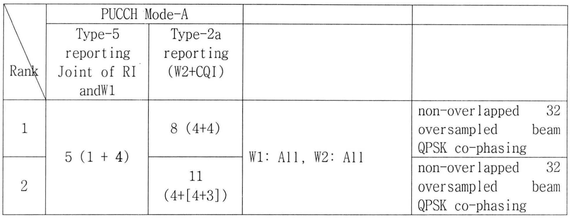


표 37 의 예시는 RI에 대한 타입-5의 비트를 5 비트로 고정하고, W1은 풀셋으로 사용할 수 있으므로 시스템 성능을 향상할 수 있다.The example in Table 37 can improve system performance because the type-5 bits for RI can be fixed to 5 bits and W1 can be used as a full set.
표 38 의 예시는 RI에 대한 타입-5의 비트를 4 비트로 사용하기 때문에 표 36 의 예시보다 더 강건하게 RI 를 전송할 수 있다. 한편, W1 의 풀셋을 사용하지 않고 서브샘플링된 W1 를 사용하므로 시스템 성능의 면에서는 표 36 의 예시에 비하여 낮은 성능을 나타낼 수 있다. 한편, 표 38, 39 및 40 의 예시에 따라 구성되는 경우에는 최대 랭크에 무관하게 랭크 1 및 2 의 W1, W2 가 동일한 세트로 구성되므로, 네스티드(nested) 특성을 가질 수 있다.The example in Table 38 allows the RI to be transmitted more robustly than the example in Table 36 because it uses 4 bits for the Type-5 bits for RI. On the other hand, since W1 sub-sampled without using a full set of W1 is used, the system performance can be lower than the example shown in Table 36. [ On the other hand, when constructed according to the examples of Tables 38, 39, and 40, W1 and W2 of the first and
위에서 설명한 PUCCH 모드-A 및 모드-B 를 비교하면, PUCCH 모드-A 에 대한 코드북 서브샘플링에 의해 공통-위상 특성(co-phase property)을 유지하면서 빔 단위(beam granularity)를 줄일 수 있다. 한편, PUCCH 모드-B 에 대한 코드북 서브샘플링에 의해 PUCCH 모드-A 에 비하여 보다 정밀한 빔 단위가 제공되지만 공통-위상 특성은 낮아지게 된다.Comparing the above-described PUCCH mode-A and mode-B, it is possible to reduce beam granularity while maintaining the common-phase property by codebook subsampling for PUCCH mode-A. On the other hand, by codebook subsampling for PUCCH mode-B, more precise beam units are provided compared to PUCCH mode-A, but the common-phase characteristic is lowered.
다음으로, 기존의 PUCCH 보고 모드 2-1 의 확장에 해당하는 PUCCH 보고 모드-C 에 대하여 설명한다.Next, the PUCCH reporting mode-C corresponding to the extension of the existing PUCCH reporting mode 2-1 will be described.
PUCCH 모드-C 에 대해 요구되는 피드백 오버헤드(피드백 비트 수)는 표 41 과 같이 나타낼 수 있다.The feedback overhead (number of feedback bits) required for PUCCH mode-C can be shown in Table 41. [

표 41에서 나타내는 바와 같이, 타입-6 의 보고에 있어서 PTI=1 인 경우에 랭크 2 내지 4 에서는 타입-8 보고를 위해 요구되는 비트가 11 비트를 초과하게 되므로, 이에 대해 코드북 서브샘플링을 적용할 수 있다. 전술한 PUCCH 모드-B 에 대해 사용된 코드북 서브샘플링과 유사한 원리가 타입-8 의 W2 에 적용될 수 있다. 또한, 표 41 에서 나타내는 바와 같이, PUCCH 모드-C 의 RI 피드백 신뢰성은, 1 비트의 PTI 지시로 인하여 전술한 PUCCH 모드-B 에 비해서 낮아지게 된다. 또한, W1 보고의 동작 주기(duty cycle)는 RI 의 동작 주기에 비해서 길게 된다. 이러한 점을 고려하여, 보고되는 타입들에 대한 보고 타이밍 및 우선순위를 결정할 수 있다.As shown in Table 41, in the case of PTI = 1 in the report of type-6, since the bits required for the type-8 report exceed 11 bits in
실시예 3Example 3
본 실시예 11 에서는 PUCCH 보고 모드에 적용될 수 있는 코드북 서브샘플링 방안에 대해서 설명한다.In the eleventh embodiment, a codebook subsampling scheme that can be applied to the PUCCH reporting mode will be described.
확장된 안테나 구성을 지원하는 시스템(예를 들어, 3GPP LTE 릴리즈-10 시스템)에서 기존의 PUCCH 보고 모드의 확장으로서, 상기 표 38 에서와 같은 3 가지의 PUCCH 보고 모드(Mode 1-1-1, Mode 1-1-2, Mode 2-1) (또는 모드-A, 모드-B, 모드-C)가 적용될 수 있다.As an extension of the existing PUCCH reporting mode in a system supporting an extended antenna configuration (for example, 3GPP LTE Release-10 system), three PUCCH reporting modes (Mode 1-1-1, Mode 1-1-2, Mode 2-1) (or Mode-A, Mode-B, Mode-C) may be applied.
Mode 1-1-1 는 조인트 코딩된 RI 및 I1 을 보고하고, 광대역 CQI 및 광대역 I2 를 보고하는 모드이다. Mode 1-1-2 는 (RI)_WB, (I1 + I2 + CQI)_WB 를 전송하는 모드이다. Mode 2-1은 PTI 에 따라 다른 피드백 정보를 전송할 수 있다. PTI=0 인 경우에는 (RI + PTI(0)), (I1)_WB, (I2 + CQI)_WB 를 전송할 수 있다. PTI=1 인 경우에는 (RI + PTI(1)), (I2 + CQI)_WB, (I2 + CQI)_SB 를 전송할 수 있다. 한편, 본 명세서에서 2 개의 프리코더 인덱스 I1 및 I2 는 각각 W1 및 W2 로 표현될 수도 있다.Mode 1-1-1 reports joint-coded RI and I1, and reports the wideband CQI and broadband I2. Mode 1-1-2 is a mode for transmitting (RI) _WB and (I1 + I2 + CQI) _WB. Mode 2-1 can transmit different feedback information according to the PTI. If PTI = 0, (RI + PTI (0)), (I1) _WB, (I2 + CQI) _WB can be transmitted. If PTI = 1, (RI + PTI (1)), (I2 + CQI) _WB, (I2 + CQI) _SB can be transmitted. In the present specification, two precoder indices I1 and I2 may be represented by W1 and W2, respectively.
이하에서는 각각의 PUCCH 보고 모드에 대해서 코드북 서브샘플링을 적용하여 보고 대역폭 최적화를 달성하면서 PUCCH 피드백 커버리지(coverage)를 기존의 3GPP LTE 릴리즈-8/9 와 같이 유지하는 방안에 대하여 설명한다.Hereinafter, a method for maintaining PUCCH feedback coverage as in the existing 3GPP LTE Release-8/9 while achieving report bandwidth optimization by applying codebook subsampling for each PUCCH reporting mode will be described.
PUCCH 보고 모드 1-1-1 및 1-1-2 에 대하여 요구되는 시그널링 오버헤드는 상기 표 35 와 같다 (표 35 에서 Mode-A 는 PUCCH 보고 모드 1-1-1 에 해당하고, Mode-B 는 PUCCH 보고 모드 1-1-2에 해당한다).Table 35 shows the signaling overhead required for the PUCCH reporting modes 1-1-1 and 1-1-2. In Table 35, Mode-A corresponds to the PUCCH reporting mode 1-1-1, Mode-B Corresponds to the PUCCH report mode 1-1-2).
상기 표 35 를 참조하여 알 수 있는 바와 같이, PUCCH 보고 모드 1-1-1 에서 타입-5(조인트 코딩된 RI 및 W1) 보고를 위해서 6 비트가 요구된다. RI 가 W1 과 조인트 코딩되면서 RI 및 W1 을 위해 6 비트가 할당되기 때문에, RI 전송의 커버리지가 기존의 3GPP LTE 릴리즈-8 시스템에 비하여 현저하게 낮아지게 된다. 이는 RI 검출실패 또는 성능 저하를 야기할 수 있다. 따라서, RI의 커버리지를 증가시키기 위해서 W1 을 서브샘플링하는 것을 고려할 수 있다. 한편, Mode 1-1-1 에서 타입-2a(W2 및 CQI) 보고는 타입-5 보고에 비하여 더 빈번하게 갱신되기 때문에, 타입-2a(W2 및 CQI)를 반드시 보호할 필요는 없다고 볼 수 있다. 따라서, 보고되는 대역폭이 1 비트 크기를 초과하지 않는 한, W2 에 대한 서브샘플링은 필요하지 않다.As can be seen with reference to Table 35 above, 6 bits are required for Type-5 (joint coded RI and W1) reporting in PUCCH reporting mode 1-1-1. Since RI is jointly coded with W1 and 6 bits are allocated for RI and W1, the coverage of the RI transmission is significantly lower than that of the existing 3GPP LTE Release-8 system. This may cause RI detection failure or performance degradation. Therefore, subsampling of W1 may be considered to increase the coverage of the RI. On the other hand, in Type 1-1-1, Type-2a (W2 and CQI) reports are more frequently updated than Type-5 reports, so Type-2a (W2 and CQI) . Thus, subsampling for W2 is not required unless the reported bandwidth exceeds a one bit size.
PUCCH 보고 모드 1-1-2 에서는 RI 가 다른 CSI 정보와 조인트 코딩되지 않으므로 RI 커버리지가 기존의 3GPP LTE 릴리즈-8 시스템과 같이 유지될 수 있다. 그러나, 상기 표 39 에서 나타내는 바와 같이, 랭크 1, 2, 3, 4 에서는 타입-2b(W1+W2+CQI) 보고에 대해서 11 비트가 초과하는 시그널링 오버헤드가 요구된다. 따라서, 3GPP LTE 릴리즈-8 의 PUCCH 포맷 2 를 재사용하기 위해서는 코드북 서브샘플링이 필요하게 된다.In the PUCCH reporting mode 1-1-2, the RI coverage can be maintained as in the existing 3GPP LTE Release-8 system since the RI is not joint coded with other CSI information. However, as shown in Table 39 above, in
우선, PUCCH 보고 모드 1-1-1 에 대해 적용될 수 있는 서브샘플링 방안에 대하여 설명한다.First, a subsampling scheme that can be applied to the PUCCH reporting mode 1-1-1 will be described.
W1 후보는 전송 랭크에 따라서 상이한 개수일 수 있다. 즉, 상기 표 11 내지 18 에서와 같이 W1 의 후보의 개수는 랭크 1 내지 8 에 대하여 각각 16개, 16 개, 4 개, 4 개, 4 개, 4 개, 4 개, 1 개가 될 수 있다. RI 및 W1 이 조인트 코딩되어 보고되는 경우, 요구되는 시그널링 오버헤드는 6 (=ceiling(log2(53))) 비트이다. RI 커버리지를 확장하기 위해서, W1 의 서브샘플링을 통해서, 시그널링 오버헤드를 5 또는 4 비트로 줄이는 것을 고려할 수 있다. W1 의 서브샘플링의 예시들은 아래의 표 42와 같다.The W1 candidate may be a different number depending on the transmission rank. That is, as shown in Tables 11 to 18, the number of W1 candidates may be 16, 16, 4, 4, 4, 4, 4, and 1 for

이중-단계(dual-stage) 코드북 구조에서는 빔 그룹 간에 중첩되는(overlapped) 빔들이 존재하므로, 표 42 의 Alt-1 방안에서와 같이 코드북에서 홀수 번호의 W1 만을 제외하는 방식으로 W1 에 대해서 서브샘플링이 적용되더라도 코드북의 모든 빔들이 유지될 수 있다. 그러나, 전체 코드북을 구성하기 위한 W1 및 W2 가 다른 서브프레임에서 전송되기 때문에, 서브샘플링이 적용되지 않는 전체 코드북을 사용하는 것에 비하여 성능 저하는 발생할 수 있다. 한편, 상기 표 42 의 Alt-2 방안에서와 같이 더 많은 빔들을 제외하는 서브샘플링되는 적용되는 경우에는, 코드북의 모든 빔을 유지하는 상기 Alt-1 방안과 달리 코드북에서 몇몇 빔들이 사용될 수 없으므로, 성능 저하가 발생할 수 있다.Since there are overlapped beams between beam groups in the dual-stage codebook structure, as in the Alt-1 scheme of Table 42, sub-sampling is performed for W1 in such a manner that only odd numbers W1 are excluded from the codebook. All the beams of the codebook can be maintained. However, since W1 and W2 for constructing the entire codebook are transmitted in different subframes, performance degradation may occur as compared to using the entire codebook to which no subsampling is applied. On the other hand, as in the Alt-2 scheme of Table 42 above, since some beams can not be used in the codebook, unlike the Alt-1 scheme that maintains all beams of the codebook, where sub-sampling is applied excluding more beams, Performance degradation can occur.
표 43 는 8×2 SU-MIMO 방식의 전송에 있어서, 코드북 서브샘플링의 적용에 따른 PUCCH 보고 모드 1-1-1 의 시스템 레벨 성능을 나타내는 것이다. 표 43 에서는, 랭크-1 및 2 에 대해 W1 및 W2 의 비트로 4+4 를 사용하는 경우를 기준으로, Alt-1 및 Alt-2 방안이 적용될 때에, 교차-극성(cross-polarized) 및 공통-극성(co-polarized) 안테나 구성의 경우에 대한 평균 스펙트럼 효율(Spectral Efficiency; SE) 및 셀-경계(cell-edge) SE 를 나타낸다. 표 43 의 Alt-1 방안에서는 평균 SE 및 셀-경계 SE 모두에서 미미한(marginal) 성능 저하가 발생하지만, Alt-2 방안에서는 셀-경계 SE 에서 상대적으로 큰 성능 저하가 발생한다.Table 43 shows the system level performance of the PUCCH reporting mode 1-1-1 according to the application of the codebook subsampling in the 8x2 SU-MIMO transmission. In Table 43, when the Alt-1 and Alt-2 schemes are applied, it is assumed that cross-polarized and common- SE < / RTI > and cell-edge SE for the case of a co-polarized antenna configuration. In the Alt-1 scheme of Table 43, a marginal performance degradation occurs in both the average SE and the cell-boundary SE, but a relatively large degradation occurs in the cell-boundary SE in the Alt-2 scheme.

표 43 에서 알 수 있는 바와 같이, 5 비트로 서브샘플링된 코드북은 시스템 성능을 유지하지만, 4 비트로 서브샘플링된 코드북은 최대 7% 만큼 시스템 성능을 감소시킨다. 따라서, Alt-1 방안이 Alt-2 방안에 비하여 RI 커버리지는 상대적으로 작게 되지만, 시스템 성능의 관점에서 보다 바람직하다.As can be seen in Table 43, a 5-bit sub-sampled codebook maintains system performance, while a 4-bit sub-sampled codebook reduces system performance by up to 7%. Therefore, although the Alt-1 scheme is relatively small in RI coverage as compared to the Alt-2 scheme, it is more preferable from the viewpoint of system performance.
다음으로, PUCCH 보고 모드 1-1-2 에 대해 적용될 수 있는 서브샘플링 방안에 대하여 설명한다.Next, a subsampling scheme that can be applied to the PUCCH reporting mode 1-1-2 will be described.
PUCCH 보고 모드 1-1-2 의 W1+W2+CQI 보고에 있어서, W1 및 W2 는 동일한 서브프레임에서 보고된다. 따라서, 보고 대역폭을 11 비트 이하로 유지하기 위해서는 서브샘플링이 적용될 수 있다. 전술한 바와 같이, W1 에 대해서 1 비트만큼 줄이는 서브샘플링이 적용되는 경우 (예를 들어, 16 개의 인덱스 중 8 개의 인덱스 서브셋을 선택하는 경우) 코드북의 모든 빔들을 유지할 수 있으므로, 시스템 성능 저하가 최소화될 수 있다. 그러나, 1 비트 보다 많이 W1를 서브샘플링하는 경우에는 코드북에서 특정 방향의 빔 그룹이 제외되게 되므로 시스템 성능 저하가 크게 발생할 수 있다. 따라서, 랭크 1 내지 4 에 대해서 W1 로부터 1 비트만큼을 서브샘플링하고, W2 에서 보다 많은 비트를 제외하도록 서브샘플링하는 것이 바람직할 수 있다. 이하의 표 44 는 PUCCH 보고 모드 1-1-2 에 적용될 수 있는 서브샘플링 방안의 예시들을 나타낸 것이다.In the W1 + W2 + CQI report of PUCCH report mode 1-1-2, W1 and W2 are reported in the same subframe. Therefore, subsampling can be applied to keep the reporting bandwidth below 11 bits. As described above, since all the beams of the codebook can be held when subsampling which reduces by one bit for W1 is applied (for example, when eight subsets of the 16 indexes are selected), it is possible to minimize system performance degradation . However, in the case of sub-sampling W1 more than 1 bit, the beam group in a specific direction is excluded from the codebook, so that the system performance may deteriorate greatly. Thus, it may be desirable to sub-sample one bit from W1 for rank one through four, and sub-sample to exclude more bits at W2. Table 44 below shows examples of subsampling schemes that can be applied to PUCCH reporting mode 1-1-2.

표 44 에서, Alt-1 및 Alt-2 방안 모두에서, 모든 빔 그룹을 잃지 않기 위해서 랭크 1 내지 4 에 대해 W1 에 1 비트만이 감소된다. 이에 따라서, W2 는 요구되는 대역폭에 따라서 서브샘플링된다.In Table 44, in both the Alt-1 and Alt-2 schemes, only one bit is reduced to W1 for
표 45 는 8×2 SU-MIMO 방식의 전송에 있어서, 표 53 의 Alt-1 및 Alt-2 방안이 적용되는 경우에 대한 PUCCH 보고 모드 1-1-2 의 시스템 레벨 성능을 나타내는 것이다. 표 45 에서는, 랭크-1 및 2 에 대해 W1 및 W2 의 비트로 4+4 를 사용하는 경우를 기준으로, Alt-1 및 Alt-2 방안이 적용될 때에, 교차-극성(cross-polarized) 및 공통-극성(co-polarized) 안테나 구성의 경우에 대한 평균 스펙트럼 효율(Spectral Efficiency; SE) 및 셀-경계(cell-edge) SE 를 나타낸다.Table 45 shows the system level performance of the PUCCH reporting mode 1-1-2 when the Alt-1 and Alt-2 schemes of Table 53 are applied in the transmission of the 8 × 2 SU-MIMO scheme. In Table 45, when the Alt-1 and Alt-2 schemes are applied, it is assumed that cross-polarized and common- SE < / RTI > and cell-edge SE for the case of a co-polarized antenna configuration.

표 45 에서 나타내는 바와 같이, 8 전송 안테나에서의 몇몇 빔 조향(steering) 벡터가 W2 서브샘플링으로부터 제외되기 때문에, 교차-극성 안테나 구성에 비하여 공통-극성 안테나 구성에서 성능 저하가 상대적으로 크게 나타난다. 한편, 교차-극성 안테나 구성에 대해서는 미미한(marginal) 성능 저하가 나타난다.As shown in Table 45, the performance degradation is relatively large in the common-polarity antenna configuration compared to the cross-polarity antenna configuration, because some beam steering vectors in the 8 transmit antennas are excluded from W2 subsampling. On the other hand, there is a marginal performance degradation for cross-polarized antenna configurations.
따라서, 3 비트로 서브샘플링된 W1 가 이용되는 경우에 서브샘플링된 코드북을 사용함으로써 발생하는 성능 저하는 수용가능한 것으로 볼 수 있다. 따라서, PUCCH 보고 모드 1-1-2 에 대해서 Alt-1 방안을 적용하는 것이 바람직하다.Thus, the performance degradation caused by using the subsampled codebook in the case of W1 sub-sampled to 3 bits is acceptable. Therefore, it is preferable to apply the Alt-1 scheme to the PUCCH report mode 1-1-2.
다음으로, PUCCH 보고 모드 2-1 에 대해 적용될 수 있는 서브샘플링 방안에 대하여 설명한다.Next, a subsampling scheme that can be applied to the PUCCH reporting mode 2-1 will be described.
PUCCH 보고 모드 2-1 에서는 4 개의 상이한 보고 타입((RI+PTI), (W1)_WB, (W2+CQI)_WB, (W2+CQI)_SB)이 피드백될 수 있다. 보고 타입은 PTI 선택에 따라서 달라질 수 있다. 상기 표 41 에서는 PUCCH 모드 2-1 (표 45 에서는 mode-C 로 표현함)의 경우에 각각의 보고 타입에 대해서 요구되는 시그널링 오버헤드에 대해서 나타낸다. 표 41 에서는 PTI=1 에서의 (W2+CQI)_SB 보고의 경우에, 단말이 선택한 서브대역에 대한 L 비트 지시자를 포함하는 것으로 가정한다.Four different reporting types ((RI + PTI), (W1) _WB, (W2 + CQI) _WB, (W2 + CQI) _SB) may be fed back in the PUCCH reporting mode 2-1. The reporting type may vary depending on the PTI selection. Table 41 shows the signaling overhead required for each report type in the case of PUCCH mode 2-1 (expressed as mode-C in Table 45). Table 41 assumes that the terminal includes an L bit indicator for the selected subband in case of (W2 + CQI) _SB report at PTI = 1.
표 41 에서 나타내는 바와 같이, PTI 가 1 이 지시되는 경우의 랭크 2, 3 및 4 의 경우에는, (W2+CQI)_SB 및 SB 에 대한 L 비트 지시자를 보고하기 위해 요구되는 오버헤드가 11 비트를 초과하게 된다. 이에 대한 시그널링 오버헤드를 감소해야, 3GPP LTE 릴리즈-8 의 PUCCH 포맷 2 를 재사용할 수 있다. 시그널링 오버헤드 감소를 위하여 다음과 같은 2 가지 방안을 고려할 수 있다. 첫 번째 방안(option 1)은, L-비트의 선택된 대역 지시자를 사용하지 않고, 미리 약속된 SB 순환(cycling)을 새롭게 정의하는 것이다. 두 번째 방안(option 2)은, W2 를 서브샘플링함으로써 L-비트의 선택된 대역 지시자를 재사용하는 것이다.As shown in Table 41, in the case of
방안 1 의 경우에, SB CQI 및 SB W2 가 PUCCH 포맷 2 를 통해서 보고될 수 있다. 그러나, 방안 1 에 따르는 경우 각각의 서브밴드에서의 CQI 보고 주기를 증가시킬 수 있으므로, 미리 정의된 SB 순환을 사용하는 것에 의해, 시간-선택적(time-selective) 채널에서 보다 민감하게 성능 저하가 발생할 수 있다. 또한, 대역폭 부분(BP) 보고 구간(duration)의 순환 사이에서 WB CQI 및 WB W2 가 보고되어야 하므로, 각각의 서브밴드에서의 CQI 보고 주기를 더욱 크게 증가시킬 수 있어서, 보다 큰 성능 저하가 나타날 수 있다.In the case of
방안 2 의 경우에, SB CQI 및 SB W2 가 L-비트의 선택된 대역 지시자와 함께 보고되므로, 랭크 2, 3 및 4 에서는 보고를 위해 요구되는 비트의 개수가 11 을 초과하게 된다. 따라서 W2 서브샘플링을 적용할 수 있으며, 아래의 표 46 에서는 W2 서브샘플링의 일례를 나타낸다.In case of

표 47 은 8×2 SU-MIMO 방식의 전송에 있어서, 전술한 2 개의 방안(option 1 및 option 2)이 적용되는 경우에 대한 PUCCH 보고 모드 2-1 의 시스템 레벨 성능을 나타내는 것이다. 표 47 에서는, 2 개의 방안이 적용될 때에, 교차-극성(cross-polarized) 및 공통-극성(co-polarized) 안테나 구성의 경우에 대한 평균 스펙트럼 효율(Spectral Efficiency; SE) 및 셀-경계(cell-edge) SE 를 나타낸다. 시스템 성능의 측정을 위해서, SB CQI 및 SB W2 가 5ms 보고 주기로 보고되고, WB W1 는 45ms 마다 갱신되는 것으로 가정한다. 또한, 방안 2 에 대해서는 2 비트로 서브샘플링된 W2 가 사용되는 것을 가정한다.Table 47 shows the system level performance of the PUCCH reporting mode 2-1 when the two schemes (

표 47 에서 나타내는 바와 같이, 방안 1 은 방안 2 에 비하여 평균 SE 에 있어서 3 내지 4% 의 시스템 성능 저하를 보인다. 이는, 방안 1 에서의 WB CQI/WB W2 보고 동작 주기가 방안 2 에서의 보고 주기에 비하여 더 길어지기 때문이다. 예를 들어, 시스템 대역폭이 5MHz 인 경우에 미리정의된 SB 순환이 적용되는 경우에서와 같이, 방안 1 에서는 모든 서브대역에 대한 CSI 를 보고하기 때문에 방안 1 에서의 WB CQI/WB W2 보고 주기가 방안 2 의 주기에 비하여 길어지게 된다.As shown in Table 47,
전술한 바와 같이, 방안 2 가 방안 1 에 비하여 높은 성능을 나타내므로, 단말이 선택한 대역에 대한 L-비트 지시자를 포함하고 W2 서브샘플링을 적용하는 것이 성능 관점에서 보다 바람직하다. 또한, 단말의 대역 선택 기능은 기존의 시스템(3GPP LTE 릴리즈-8 시스템)에서 사용된 것이므로, 방안 2 의 구현의 복잡성 역시 감소하게 된다.As described above, since
따라서, PUCCH 모드 각각에 대하여 적용되는 본 발명에서 제안하는 코드북 서브샘플링 방안에 따르면, 기존의 PUCCH 포맷 2 를 재사용하면서 시스템 성능의 감소를 최소화할 수 있다.Therefore, according to the codebook subsampling scheme proposed in the present invention, which is applied to each PUCCH mode, reduction in system performance can be minimized while reusing the existing
한편, 이하의 표 48 은 상기 표 43, 45 및 47 의 시스템 성능의 시뮬레이션에 적용된 파라미터들을 나타내는 것이다. 또한, 표 49, 50 및 51 은 각각 PUCCH 포맷 1-1-1, 1-1-2 및 2-1 의 시스템 성능의 시뮬레이션에 적용된 파라미터들을 나타낸 것이다.Table 48 below shows the parameters applied to the simulation of the system performance of Tables 43, 45 and 47 above. Tables 49, 50, and 51 show parameters applied to the simulation of the system performance of the PUCCH formats 1-1-1, 1-1-2, and 2-1, respectively.


실시예 4Example 4
본 실시예 4 에서는 W1 및 W2 가 조인트 코딩되는 경우에 적용될 수 있는 W1 및 W2 의 서브샘플링 방안에 대하여 설명한다.In the fourth embodiment, a sub-sampling scheme of W1 and W2 that can be applied when W1 and W2 are joint-coded will be described.
상기 표 34 의 PUCCH 보고 모드 1-1-2 의 경우에, W1 및 W2 가 WB CQI 와 함께 전송된다 (표 34 에서는 W1 및 W2 를 I1 및 I2 으로 나타낸다). 기존의 3GPP LTE 릴리즈-8 의 PUCCH 보고 방식에서의 에러 발생확률과 동일한 수준을 가지도록 피드백 모드를 설정하기 위해서, 각각의 랭크의 프리코더에 대한 비트는 4 비트 크기를 가지도록 설계할 수 있다.In the case of the PUCCH report mode 1-1-2 in Table 34, W1 and W2 are transmitted together with the WB CQI (W1 and W2 are denoted by I1 and I2 in Table 34). In order to set the feedback mode to have the same level of error occurrence probability in the PUCCH reporting method of the existing 3GPP LTE Release-8, the bit for the precoder of each rank can be designed to have a 4-bit size.
예를 들어, 표 52 와 같이 각각의 랭크에 따른 W1 및 W2 의 비트수를 설정할 수 있다. 표 52 에서 설명하는 W1 및 W2 에 대한 인덱스는 상기 표 11 내지 14 에서 나타내는 코드북에 대한 인덱스 (i1, i2) 에 해당한다. 표 52 에서는 W1 및 W2 의 서브샘플링 방안의 4 가지 예시에 대해서 나타낸다.For example, as shown in Table 52, the number of bits of W1 and W2 according to each rank can be set. The indices for W1 and W2 described in Table 52 correspond to the indices (i1, i2) for the codebooks shown in Tables 11 to 14 above. Table 52 shows four examples of subsampling schemes for W1 and W2.

실시예 5Example 5
본 실시예 5 에서는 PUCCH 보고 모드 2-1 에 적용될 수 있는 W2 서브샘플링 방안에 대하여 설명한다.In the fifth embodiment, the W2 subsampling scheme applicable to the PUCCH reporting mode 2-1 will be described.
상기 표 34 에서 설명한 PUCCH 보고 모드 2-1 에서, PTI=1 인 경우에 SB CQI 가 전송될 때, SB CQI 는 대역폭 부분(BP) 내에서 선택될 수 있다. 즉, 제 1 보고 시간에 WB CQI와 WB W2가 보고되고, 제 2 보고 시간에 어떤 BP 내에서 선택된 SB CQI, 선택된 대역 인덱스 및 SB W2가 보고된다 (표 38 에서는 W1 및 W2 를 I1 및 I2 으로 나타낸다). 제 3 보고 시간에는, 제 2 보고 시간에 고려된 BP 와 다른 BP 내에서 선택된 SB CQI, 선택된 대역 인덱스 및 SB W2가 보고된다.In the PUCCH reporting mode 2-1 described in Table 34 above, when the SB CQI is transmitted when PTI = 1, the SB CQI can be selected in the bandwidth part BP. In other words, the WB CQI and WB W2 are reported at the first reporting time, and the selected SB CQI, the selected band index and the SB W2 are reported in a BP at the second reporting time (in Table 38, W1 and W2 are reported as I1 and I2 ). At the third reporting time, the SB CQI selected in the BP different from the BP considered at the second reporting time, the selected band index and SB W2 are reported.
여기서, SB CQI 는 4 비트 또는 7 비트로 표현된다. 선택된 대역 인덱스는 2 비트로 표현되고, SB W2 는 4 비트로 표현된다. 이를 고려하면, 하나의 보고 시간 (즉, 하나의 서브프레임) 에서 전송되어야 하는 비트의 총합으로 10 또는 13 비트가 요구된다. 그러나, 전술한 바와 같이 PUCCH 를 통해 (예를 들어, PUCCH 포맷 2 를 사용하는 경우) 전송될 수 있는 피드백 정보의 비트 수가 11 비트로 제한되는 것을 고려하면, 랭크-2 이상에서 2 비트를 줄여야 한다.Here, the SB CQI is represented by 4 bits or 7 bits. The selected band index is represented by 2 bits, and SB W2 is represented by 4 bits. Taking this into consideration, 10 or 13 bits are required as the sum of the bits to be transmitted in one reporting time (i.e., one subframe). However, considering that the number of bits of the feedback information that can be transmitted over the PUCCH (for example, using PUCCH format 2) as described above is limited to 11 bits, it is necessary to reduce 2 bits by at least Rank-2.
W2 에서 2 비트를 줄이는 방안으로서, 다음의 표 53 과 같은 W2 서브대역 보고를 적용할 수 있다. 표 53 은 8 전송 안테나 전송의 경우에, 랭크-2, 3 및 4 에 있어서 W2 서브샘플링을 적용하는 2 가지 예시를 나타낸다.As a way to reduce 2 bits in W2, the W2 subband report as shown in Table 53 below can be applied. Table 53 shows two examples of applying W2 subsampling for rank-2, 3 and 4 for 8 transmit antenna transmission.

또한, W2 의 서브샘플링을 적용하는 경우에, W1 및 W2 를 통해서 프리코더가 특정되므로, 프리코더 요소의 누락을 피하기 위해서 W1 에 대해서는 서브샘플링을 적용하지 않는 것을 고려할 수 있다.In addition, in the case of applying the subsampling of W2, since the precoder is specified through W1 and W2, it can be considered not to apply subsampling to W1 in order to avoid omission of the precoder element.
본 실시예 5 에 있어서 W2 를 2 비트로 서브샘플링하는 구체적인 방안으로서 전술한 본 발명의 다양한 실시예들에서 설명한 방안이 적용될 수 있다.In the fifth embodiment, the method described in the various embodiments of the present invention described above can be applied as a specific method of sub-sampling W2 to 2 bits.
도 22 를 참조하여 본 발명의 바람직한 실시예에 따른 채널상태정보 보고 방법에 대하여 설명한다.A method of reporting channel state information according to a preferred embodiment of the present invention will be described with reference to FIG.
기지국으로부터 단말로의 하향링크 전송에 대해 단말이 하향링크 채널상태를 측정하고 그 결과를 기지국으로 상향링크를 통해서 피드백할 수 있다. 예를 들어, 기지국의 하향링크 전송에 8 전송 안테나가 사용되는 경우에, 기지국은 채널상태정보-참조신호(CSI-RS)를 8 개의 안테나 포트(안테나 포트 인덱스 15 내지 22)를 통해 전송할 수 있다. 단말은 상기 CSI-RS 를 통해서 하향링크 채널 상태를 측정한 결과 (RI, PMI, CQI 등)를 전송할 수 있다. RI/PMI/CQI 의 선택/산출의 구체적인 방안은 전술한 본 발명의 다양한 예시들이 적용될 수 있다. 기지국은 수신한 채널상태정보(RI/PMI/CQI)에 따라서 하향링크 전송의 레이어의 개수, 프리코더, 변조및코딩기법(MCS) 레벨 등을 결정할 수 있고, 이에 따라 하향링크 신호를 전송할 수 있다.The terminal measures the downlink channel state for downlink transmission from the base station to the terminal and can feedback the result to the base station through the uplink. For example, if 8 transmit antennas are used for downlink transmission of a base station, the base station may transmit the channel state information-reference signal (CSI-RS) through eight antenna ports (
도 22 의 단계 S2210 에서 단말은 제 1 서브프레임에서 RI를 전송할 수 있다. 단계 S2220 에서 단말은 제 2 서브프레임에서 제 1 PMI, 제 2 PMI 및 광대역 CQI를 전송할 수 있다. 제 1 PMI 및 제 2 PMI 의 조합에 의해 단말이 선호하는(preferred) 프리코딩 행렬이 지시될 수 있다. 예를 들어, 제 1 PMI 는 상기 하향링크 전송에 대하여 적용되는 프리코딩 행렬의 후보들(candidates)을 지시(indicate)하고, 상기 제 2 PMI 는 상기 후보들 중 하나의 프리코딩 행렬을 지시할 수 있다.In step S2210 of FIG. 22, the terminal may transmit the RI in the first subframe. In step S2220, the UE can transmit the first PMI, the second PMI, and the wideband CQI in the second subframe. The combination of the first PMI and the second PMI may indicate a preferred precoding matrix of the terminal. For example, a first PMI may indicate candidates of a precoding matrix to be applied for the downlink transmission, and the second PMI may indicate a precoding matrix of one of the candidates.
제 1 PMI (i1 또는 W1) 및 제 2 PMI (i2 또는 W2) 에 대하여 서브샘플링된 코드북이 적용될 수 있다. 서브샘플링된 코드북은 상기 표 11 내지 18 과 같은 코드북에서 일부 인덱스만으로 구성된 코드북을 의미한다. 서브샘플링이 적용되기 전의 코드북에서는 랭크 1 및 2 의 경우에 제 1 PMI 에 대해 4 비트, 제 2 PMI 에 대해 4 비트가 요구된다. 한편, 본 발명에 따라 서브샘플링된 코드북에서는 랭크 1 내지 4 각각에 대해서 상기 제 1 PMI 및 상기 제 2 PMI는 합하여 4 비트의 길이를 가질 수 있다.A sub-sampled codebook may be applied to the first PMI (i1 or W1) and the second PMI (i2 or W2). The sub-sampled codebook means a codebook composed of only some indices in the codebook as shown in Tables 11 to 18. [ In the codebook before subsampling is applied, 4 bits are required for the first PMI and 4 bits for the second PMI in the case of
랭크 1 또는 랭크 2 의 경우에 제 1 PMI 및 제 2 PMI 가 각각 3 비트 및 1 비트의 길이를 가질 수 있다. 랭크 1 에 대해서, 제 1 PMI 는 0, 2, 4, 6, 8, 10, 12, 14 중 하나의 값을 가지고, 제 2 PMI 는 0, 2 중 하나의 값을 가질 수 있다. 또한, 랭크 2 에 대해서, 제 1 PMI 는 0, 2, 4, 6, 8, 10, 12, 14 중 하나의 값을 가지고, 제 2 PMI 는 0, 1 중 하나의 값을 가질 수 있다.In the case of
랭크 3 또는 4 각각에 대하여, 제 1 PMI 및 제 2 PMI 가 각각 1 비트 및 3 비트의 길이를 가질 수 있다. 랭크 3 에 대해서, 제 1 PMI 는 0, 2 중 하나의 값을 가지고, 제 2 PMI 는 0, 1, 2, 3, 8, 9, 10, 11 중 하나의 값을 가질 수 있다. 또한, 랭크 4 에 대해서, 제 1 PMI 는 0, 2 중 하나의 값을 가지고, 제 2 PMI 는 0, 1, 2, 3, 4, 5, 6, 7 중 하나의 값을 가질 수 있다.For each
상기 채널상태정보(RI, 제 1 PMI, 제 2 PMI 및 CQI)는, 각각의 상향링크 서브프레임에서 PUCCH를 통해 전송될 수 있다. 즉, 주기적 방식으로 채널상태정보가 전송되며, 각각의 채널상태정보(조인트 코딩된 RI 및 제 1 PMI / CQI 및 제 2 PMI)는 각자의 보고 주기에 따라 전송될 수 있다. 채널상태정보의 보고 주기는 전술한 본 발명의 다양한 예시에 따라 결정될 수 있다.The channel state information (RI, first PMI, second PMI, and CQI) may be transmitted on the PUCCH in each uplink subframe. That is, channel state information is transmitted in a periodic manner, and channel state information (jointly coded RI and first PMI / CQI and second PMI) of each channel can be transmitted in accordance with each reporting period. The reporting period of the channel state information may be determined according to various examples of the present invention described above.
도 22 와 관련하여 설명한 본 발명의 채널상태정보 전송방법에 있어서, 전술한 본 발명의 다양한 실시예에서 설명한 사항들이 독립적으로 적용되거나 또는 2 이상의 실시예가 동시에 적용될 수 있으며, 중복되는 내용은 명확성을 위하여 설명을 생략한다.In the channel state information transmission method of the present invention described with reference to FIG. 22, the items described in the various embodiments of the present invention described above may be applied independently, or two or more embodiments may be applied at the same time. For the sake of clarity, The description will be omitted.
또한, 기지국과 중계기간의 (백홀 상향링크 및 백홀 하향링크에서의) MIMO 전송 및 중계기와 단말간의 (액세스 상향링크 및 액세스 하향링크에서의) MIMO 전송에 대한 채널상태정보 피드백에 대해서도 본 발명에서 제안하는 동일한 원리가 적용될 수 있다.Also, channel state information feedback for MIMO transmission (in the backhaul uplink and backhaul downlink) and MIMO transmission (in the access uplink and access downlink) between the base station and the relay station and between the relay station and the terminal is also proposed in the present invention The same principle can be applied.
도 23 은 본 발명에 따른 기지국 장치 및 단말 장치의 구성을 도시한 도면이다.23 is a diagram showing a configuration of a base station apparatus and a terminal apparatus according to the present invention.
도 23를 참조하여 본 발명에 따른 기지국 장치(2310)는, 수신모듈(2311), 전송모듈(2312), 프로세서(2313), 메모리(2314) 및 복수개의 안테나(2315)를 포함할 수 있다. 복수개의 안테나(2315)는 MIMO 송수신을 지원하는 기지국 장치를 의미한다. 수신모듈(2311)은 단말로부터의 상향링크 상의 각종 신호, 데이터 및 정보를 수신할 수 있다. 전송모듈(2312)은 단말로의 하향링크 상의 각종 신호, 데이터 및 정보를 전송할 수 있다. 프로세서(2313)는 기지국 장치(2310) 전반의 동작을 제어할 수 있다.23, a
본 발명의 일 실시예에 따른 기지국 장치(2310)는 최대 8 전송 안테나를 통한 하향링크 전송을 하고, 하향링크 전송에 대한 채널상태정보를 단말 장치(2320)로부터 수신하도록 구성될 수 있다. 기지국 장치의 프로세서(2313)는, 수신 모듈(2311)을 통하여, 제 1 서브프레임에서 랭크 지시자(RI)를 수신하고, 제 2 서브프레임에서 제 1 프리코딩행렬지시자(PMI), 제 2 PMI 및 광대역 채널품질지시자(CQI)를 수신하도록 구성될 수 있다. 여기서, 상기 제 1 PMI 및 상기 제 2 PMI 의 조합에 의해 단말이 선호하는(preferred) 프리코딩 행렬이 지시될 수 있다. 또한, 상기 제 1 PMI 및 상기 제 2 PMI 에 대하여 서브샘플링된 코드북이 적용되고, 상기 서브샘플링된 코드북에서 랭크 1 내지 4 각각에 대해서 상기 제 1 PMI 및 상기 제 2 PMI는 합하여 4 비트로 구성될 수 있다.The
기지국 장치(2310)의 프로세서(2313)는 그 외에도 기지국 장치(2310)가 수신한 정보, 외부로 전송할 정보 등을 연산 처리하는 기능을 수행하며, 메모리(2314)는 연산 처리된 정보 등을 소정시간 동안 저장할 수 있으며, 버퍼(미도시) 등의 구성요소로 대체될 수 있다.The
도 23를 참조하여 본 발명에 따른 단말 장치(2320)는, 수신모듈(2321), 전송모듈(2322), 프로세서(2323), 메모리(2324) 및 복수개의 안테나(2325)를 포함할 수 있다. 복수개의 안테나(2325)는 MIMO 송수신을 지원하는 단말 장치를 의미한다. 수신모듈(2321)은 기지국으로부터의 하향링크 상의 각종 신호, 데이터 및 정보를 수신할 수 있다. 전송모듈(2322)은 기지국으로의 상향링크 상의 각종 신호, 데이터 및 정보를 전송할 수 있다. 프로세서(2323)는 단말 장치(2320) 전반의 동작을 제어할 수 있다.23, a
본 발명의 일 실시예에 따른 단말 장치(2320)는 기지국 장치(2310)로부터의 최대 8 전송 안테나를 통한 하향링크 전송을 수신하고, 이러한 하향링크 전송에 대한 채널상태정보를 기지국으로 피드백하도록 구성될 수 있다. 단말 장치의 프로세서(2323)는, 전송 모듈(2322)을 통하여, 제 1 서브프레임에서 랭크 지시자(RI)를 전송하고, 제 2 서브프레임에서 제 1 프리코딩행렬지시자(PMI), 제 2 PMI 및 광대역 채널품질지시자(CQI)를 전송하도록 구성될 수 있다. 상기 제 1 PMI 및 상기 제 2 PMI 의 조합에 의해 단말이 선호하는(preferred) 프리코딩 행렬이 지시될 수 있다. 상기 제 1 PMI 및 상기 제 2 PMI 에 대하여 서브샘플링된 코드북이 적용되고, 상기 서브샘플링된 코드북에서 랭크 1 내지 4 각각에 대해서 상기 제 1 PMI 및 상기 제 2 PMI는 합하여 4 비트로 구성될 수 있다.The
단말 장치(2320)의 프로세서(2323)는 그 외에도 단말 장치(2320)가 수신한 정보, 외부로 전송할 정보 등을 연산 처리하는 기능을 수행하며, 메모리(2324)는 연산 처리된 정보 등을 소정시간 동안 저장할 수 있으며, 버퍼(미도시) 등의 구성요소로 대체될 수 있다.The
위와 같은 기지국 장치 및 단말 장치의 구체적인 구성은, 전술한 본 발명의 다양한 실시예에서 설명한 사항들이 독립적으로 적용되거나 또는 2 이상의 실시예가 동시에 적용되도록 구현될 수 있으며, 중복되는 내용은 명확성을 위하여 설명을 생략한다.The specific configuration of the base station apparatus and the terminal apparatus may be implemented such that the above-described embodiments of the present invention are applied independently or two or more embodiments may be simultaneously applied. For the sake of clarity, It is omitted.
또한, 도 23에 대한 설명에 있어서 기지국 장치(2310)에 대한 설명은 하향링크 전송 주체 또는 상향링크 수신 주체로서의 중계기 장치에 대해서도 동일하게 적용될 수 있고, 단말 장치(2320)에 대한 설명은 하향링크 수신 주체 또는 상향링크 전송 주체로서의 중계기 장치에 대해서도 동일하게 적용될 수 있다.The description of the
상술한 본 발명의 실시예들은 다양한 수단을 통해 구현될 수 있다. 예를 들어, 본 발명의 실시예들은 하드웨어, 펌웨어(firmware), 소프트웨어 또는 그것들의 결합 등에 의해 구현될 수 있다.The above-described embodiments of the present invention can be implemented by various means. For example, embodiments of the present invention may be implemented by hardware, firmware, software, or a combination thereof.
하드웨어에 의한 구현의 경우, 본 발명의 실시예들에 따른 방법은 하나 또는 그 이상의 ASICs(Application Specific Integrated Circuits), DSPs(Digital Signal Processors), DSPDs(Digital Signal Processing Devices), PLDs(Programmable Logic Devices), FPGAs(Field Programmable Gate Arrays), 프로세서, 컨트롤러, 마이크로 컨트롤러, 마이크로 프로세서 등에 의해 구현될 수 있다.In the case of hardware implementation, the method according to embodiments of the present invention may be implemented in one or more Application Specific Integrated Circuits (ASICs), Digital Signal Processors (DSPs), Digital Signal Processing Devices (DSPDs), Programmable Logic Devices (PLDs) , FPGAs (Field Programmable Gate Arrays), processors, controllers, microcontrollers, microprocessors, and the like.
펌웨어나 소프트웨어에 의한 구현의 경우, 본 발명의 실시예들에 따른 방법은 이상에서 설명된 기능 또는 동작들을 수행하는 모듈, 절차 또는 함수 등의 형태로 구현될 수 있다. 소프트웨어 코드는 메모리 유닛에 저장되어 프로세서에 의해 구동될 수 있다. 상기 메모리 유닛은 상기 프로세서 내부 또는 외부에 위치하여, 이미 공지된 다양한 수단에 의해 상기 프로세서와 데이터를 주고 받을 수 있다.In the case of an implementation by firmware or software, the method according to embodiments of the present invention may be implemented in the form of a module, a procedure or a function for performing the functions or operations described above. The software code can be stored in a memory unit and driven by the processor. The memory unit may be located inside or outside the processor, and may exchange data with the processor by various well-known means.
상술한 바와 같이 개시된 본 발명의 바람직한 실시예들에 대한 상세한 설명은 당업자가 본 발명을 구현하고 실시할 수 있도록 제공되었다. 상기에서는 본 발명의 바람직한 실시예들을 참조하여 설명하였지만, 해당 기술 분야의 숙련된 당업자는 본 발명의 영역으로부터 벗어나지 않는 범위 내에서 본 발명을 다양하게 수정 및 변경시킬 수 있음을 이해할 수 있을 것이다. 예를 들어, 당업자는 상술한 실시예들에 기재된 각 구성을 서로 조합하는 방식으로 이용할 수 있다. 따라서, 본 발명은 여기에 나타난 실시형태들에 제한되려는 것이 아니라, 여기서 개시된 원리들 및 신규한 특징들과 일치하는 최광의 범위를 부여하려는 것이다.DETAILED DESCRIPTION OF THE PREFERRED EMBODIMENTS The foregoing description of the preferred embodiments of the invention disclosed herein has been presented to enable any person skilled in the art to make and use the present invention. While the present invention has been particularly shown and described with reference to preferred embodiments thereof, it will be understood by those skilled in the art that various changes and modifications may be made therein without departing from the spirit and scope of the invention as defined by the appended claims. For example, those skilled in the art can utilize each of the configurations described in the above-described embodiments in a manner of mutually combining them. Accordingly, the present invention is not intended to be limited to the embodiments shown herein but is to be accorded the widest scope consistent with the principles and novel features disclosed herein.
본 발명은 본 발명의 정신 및 필수적 특징을 벗어나지 않는 범위에서 다른 특정한 형태로 구체화될 수 있다. 따라서, 상기의 상세한 설명은 모든 면에서 제한적으로 해석되어서는 아니 되고 예시적인 것으로 고려되어야 한다. 본 발명의 범위는 첨부된 청구항의 합리적 해석에 의해 결정되어야 하고, 본 발명의 등가적 범위 내에서의 모든 변경은 본 발명의 범위에 포함된다. 본 발명은 여기에 나타난 실시형태들에 제한되려는 것이 아니라, 여기서 개시된 원리들 및 신규한 특징들과 일치하는 최광의 범위를 부여하려는 것이다. 또한, 특허청구범위에서 명시적인 인용관계가 있지 않은 청구항들을 결합하여 실시예를 구성하거나 출원 후의 보정에 의해 새로운 청구항으로 포함할 수 있다.The present invention may be embodied in other specific forms without departing from the spirit or essential characteristics thereof. Accordingly, the above description should not be construed in a limiting sense in all respects and should be considered illustrative. The scope of the present invention should be determined by rational interpretation of the appended claims, and all changes within the scope of equivalents of the present invention are included in the scope of the present invention. The present invention is not intended to be limited to the embodiments shown herein but is to be accorded the widest scope consistent with the principles and novel features disclosed herein. In addition, claims that do not have an explicit citation in the claims may be combined to form an embodiment or be included in a new claim by amendment after the filing.
2310 기지국 2320 단말
2311, 2321 수신모듈 2312, 2322 전송모듈
2313, 2323 프로세서 2314, 2324 메모리
2315, 2325 안테나2310
2311 and 2321
2313, 2323
2315, 2325 antenna
Claims (22)
제 1 서브프레임에서 랭크 지시자(RI)를 보고하는 제1 CSI를 전송하는 단계; 및
제 2 서브프레임에서 제 1 프리코딩행렬지시자(PMI), 제 2 PMI 및 광대역 채널품질지시자(CQI)를 보고하는 제2 CSI를 전송하는 단계를 포함하고,
상기 제 1 PMI 및 상기 제 2 PMI 의 조합에 의해 단말이 선호하는(preferred) 프리코딩 행렬이 지시되며,
상기 RI가 랭크 1 내지 랭크 4 중 어느 하나에 해당하는 경우, 상기 제 1 PMI 및 상기 제 2 PMI 에 대하여 해당 랭크에 대한 프리코딩 코드북의 서브샘플링된 코드북이 적용되고, 상기 서브샘플링된 코드북에서 상기 제 1 PMI 및 상기 제 2 PMI는 합하여 4 비트로 구성되고,
상기 RI가 랭크 5 내지 랭크 7 중 어느 하나에 해당하는 경우, 상기 제 1 PMI 및 상기 제 2 PMI 에 대하여 해당 랭크에 대한 프리코딩 코드북의 전체 세트(full-set)가 적용되고, 상기 제 1 PMI 및 상기 제 2 PMI는 합하여 2 비트로 구성되는, 채널상태정보 전송 방법.A method for transmitting channel state information (CSI) for a downlink transmission in an uplink in a wireless communication system,
Transmitting a first CSI reporting a rank indicator (RI) in a first sub-frame; And
Transmitting a second CSI reporting a first precoding matrix indicator (PMI), a second PMI and a wideband channel quality indicator (CQI) in a second subframe,
A preferred precoding matrix is indicated by the combination of the first PMI and the second PMI,
A sub-sampled codebook of a precoding codebook for a corresponding rank is applied to the first PMI and the second PMI when the RI corresponds to any of rank 1 to rank 4, The first PMI and the second PMI are composed of 4 bits in total,
A full set of precoding codebook for the rank is applied to the first PMI and the second PMI when the RI corresponds to any of rank 5 to rank 7, And the second PMI are composed of 2 bits in total.
랭크 1 및 2 각각에 대하여, 상기 서브샘플링된 코드북에서 상기 제 1 PMI 는 3 비트로 구성되고 상기 제 2 PMI 는 1 비트로 구성되는, 채널상태정보 전송 방법.The method according to claim 1,
For each of the first and second rankings, in the sub-sampled codebook, the first PMI consists of three bits and the second PMI consists of one bit.
랭크 1 에 대한 상기 프리코딩 코드북은

(여기서,

랭크 1 에 대해서, 상기 제 1 PMI 는 0, 2, 4, 6, 8, 10, 12, 14 중 하나의 값을 가지고, 상기 제 2 PMI 는 0, 2 중 하나의 값을 가지는, 채널상태정보 전송 방법.3. The method of claim 2,
The precoding codebook for rank 1
(here,
The first PMI has a value of one of 0, 2, 4, 6, 8, 10, 12, and 14 and the second PMI has a value of one of 0 and 2, Transmission method.
랭크 2 에 대한 상기 프리코딩 코드북은

(여기서,

랭크 2 에 대해서, 상기 제 1 PMI 는 0, 2, 4, 6, 8, 10, 12, 14 중 하나의 값을 가지고, 상기 제 2 PMI 는 0, 1 중 하나의 값을 가지는, 채널상태정보 전송 방법.3. The method of claim 2,
The precoding codebook for rank 2
(here,
The first PMI has a value of one of 0, 2, 4, 6, 8, 10, 12, and 14 and the second PMI has a value of one of 0 and 1, Transmission method.
랭크 3 및 4 각각에 대하여, 상기 서브샘플링된 코드북에서 상기 제 1 PMI 는 1 비트로 구성되고 상기 제 2 PMI 는 3 비트로 구성되는, 채널상태정보 전송 방법.The method according to claim 1,
For each of the rank 3 and 4, in the sub-sampled codebook, the first PMI consists of one bit and the second PMI consists of three bits.
랭크 3 에 대한 상기 프리코딩 코드북은

(여기서,

랭크 3 에 대해서, 상기 제 1 PMI 는 0, 2 중 하나의 값을 가지고, 상기 제 2 PMI 는 0, 1, 2, 3, 8, 9, 10, 11 중 하나의 값을 가지는, 채널상태정보 전송 방법.6. The method of claim 5,
The precoding codebook for rank 3 is
(here,
For the rank 3, the first PMI has a value of 0 or 2, and the second PMI has a value of one of 0, 1, 2, 3, 8, 9, 10, Transmission method.
랭크 4 에 대한 상기 프리코딩 코드북은

(여기서, ) 로 구성되고,
랭크 4 에 대해서, 상기 제 1 PMI 는 0, 2 중 하나의 값을 가지고, 상기 제 2 PMI 는 0, 1, 2, 3, 4, 5, 6, 7 중 하나의 값을 가지는, 채널상태정보 전송 방법.6. The method of claim 5,
The precoding codebook for rank 4 is
(here, ),
For the rank 4, the first PMI has a value of 0 or 2, and the second PMI has a value of one of 0, 1, 2, 3, 4, 5, 6, Transmission method.
상기 제1 CSI 및 상기 제2 CSI는 하향링크 8 전송 안테나 전송에 대한 것으로서,
상기 RI를 보고하는 제1 CSI 는 제1 보고 주기에 따라 상기 제 1 서브프레임의 물리상향링크제어채널(PUCCH)을 통해서 전송되고,
상기 제 1 PMI, 제 2 PMI 및 CQI를 보고하는 제2 CSI 는 제2 보고 주기에 따라 상기 제 2 서브프레임의 PUCCH를 통해서 전송되는, 채널상태정보 전송 방법.The method according to claim 1,
The first CSI and the second CSI are for downlink 8 transmit antenna transmission,
The first CSI reporting the RI is transmitted on a physical uplink control channel (PUCCH) of the first subframe according to a first reporting period,
Wherein the second CSI reporting the first PMI, the second PMI, and the CQI is transmitted on the PUCCH of the second subframe according to a second reporting period.
제 1 서브프레임에서 랭크 지시자(RI)를 수신하는 단계; 및
제 2 서브프레임에서 제 1 프리코딩행렬지시자(PMI), 제 2 PMI 및 광대역 채널품질지시자(CQI)를 수신하는 단계를 포함하고,
상기 제 1 PMI 및 상기 제 2 PMI 의 조합에 의해 단말이 신호하는(preferred) 프리코딩 행렬이 지시되며,
상기 제 1 PMI 및 상기 제 2 PMI 에 대하여 랭크 1 내지 4 각각에 대한 프리코딩 코드북의 서브샘플링된 코드북이 적용되고, 상기 서브샘플링된 코드북에서 랭크 1 내지 4 각각에 대해서 상기 제 1 PMI 및 상기 제 2 PMI는 합하여 4 비트로 구성되는, 채널상태정보 수신 방법.A method for receiving channel state information for a downlink transmission in an uplink in a wireless communication system,
Receiving a rank indicator (RI) in a first subframe; And
Receiving a first precoding matrix indicator (PMI), a second PMI, and a wideband channel quality indicator (CQI) in a second subframe,
Wherein a precoding matrix is indicated by a combination of the first PMI and the second PMI,
A sub-sampled codebook of a precoding codebook for each of the first to fourth PMIs for the first PMI and the second PMI is applied, and for each of the ranks 1 to 4 in the sub-sampled codebook, 2 < / RTI > PMIs are combined into 4 bits.
랭크 1 및 2 각각에 대하여, 상기 서브샘플링된 코드북에서 상기 제 1 PMI 는 3 비트로 구성되고 상기 제 2 PMI 는 1 비트로 구성되는, 채널상태정보 수신 방법.12. The method of claim 11,
For each of the first and second rankings, in the sub-sampled codebook, the first PMI consists of three bits and the second PMI consists of one bit.
랭크 1 에 대한 상기 프리코딩 코드북은

(여기서,

랭크 1 에 대해서, 상기 제 1 PMI 는 0, 2, 4, 6, 8, 10, 12, 14 중 하나의 값을 가지고, 상기 제 2 PMI 는 0, 2 중 하나의 값을 가지는, 채널상태정보 수신 방법.13. The method of claim 12,
The precoding codebook for rank 1
(here,
The first PMI has a value of one of 0, 2, 4, 6, 8, 10, 12, and 14 and the second PMI has a value of one of 0 and 2, Receiving method.
랭크 2 에 대한 상기 프리코딩 코드북은

(여기서,

랭크 2 에 대해서, 상기 제 1 PMI 는 0, 2, 4, 6, 8, 10, 12, 14 중 하나의 값을 가지고, 상기 제 2 PMI 는 0, 1 중 하나의 값을 가지는, 채널상태정보 수신 방법.13. The method of claim 12,
The precoding codebook for rank 2
(here,
The first PMI has a value of one of 0, 2, 4, 6, 8, 10, 12, and 14 and the second PMI has a value of one of 0 and 1, Receiving method.
랭크 3 및 4 각각에 대하여, 상기 서브샘플링된 코드북에서 상기 제 1 PMI 는 1 비트로 구성되고 상기 제 2 PMI 는 3 비트로 구성되는, 채널상태정보 수신 방법.12. The method of claim 11,
For each of the rank 3 and 4, in the sub-sampled codebook, the first PMI consists of one bit and the second PMI consists of three bits.
랭크 3 에 대한 상기 프리코딩 코드북은

(여기서,

랭크 3 에 대해서, 상기 제 1 PMI 는 0, 2 중 하나의 값을 가지고, 상기 제 2 PMI 는 0, 1, 2, 3, 8, 9, 10, 11 중 하나의 값을 가지는, 채널상태정보 수신 방법.16. The method of claim 15,
The precoding codebook for rank 3 is
(here,
For the rank 3, the first PMI has a value of 0 or 2, and the second PMI has a value of one of 0, 1, 2, 3, 8, 9, 10, Receiving method.
랭크 4 에 대한 상기 프리코딩 코드북은

(여기서,

랭크 4 에 대해서, 상기 제 1 PMI 는 0, 2 중 하나의 값을 가지고, 상기 제 2 PMI 는 0, 1, 2, 3, 4, 5, 6, 7 중 하나의 값을 가지는, 채널상태정보 수신 방법.16. The method of claim 15,
The precoding codebook for rank 4 is
(here,
For the rank 4, the first PMI has a value of 0 or 2, and the second PMI has a value of one of 0, 1, 2, 3, 4, 5, 6, Receiving method.
제1 CSI 및 제2 CSI는 하향링크 8 전송 안테나 전송에 대한 것으로서,
상기 RI를 보고하는 제1 CSI 는 제1 보고 주기에 따라 상기 제 1 서브프레임의 물리상향링크제어채널(PUCCH)을 통해서 수신되고,
상기 제 1 PMI, 제 2 PMI 및 CQI를 보고하는 제2 CSI 는 제2 보고 주기에 따라 상기 제 2 서브프레임의 PUCCH를 통해서 수신되는, 채널상태정보 수신 방법.12. The method of claim 11,
The first CSI and the second CSI are for downlink 8 transmit antenna transmission,
The first CSI reporting the RI is received on a physical uplink control channel (PUCCH) of the first subframe according to a first reporting period,
Wherein the second CSI reporting the first PMI, the second PMI and the CQI is received on the PUCCH of the second subframe according to a second reporting period.
기지국으로부터 하향링크 신호를 수신하는 수신 모듈;
상기 기지국으로 상향링크 신호를 전송하는 전송 모듈; 및
상기 수신 모듈 및 상기 전송 모듈을 포함하는 상기 단말을 제어하는 프로세서를 포함하며,
상기 프로세서는, 상기 전송 모듈을 통하여, 제 1 서브프레임에서 랭크 지시자(RI)를 보고하는 제1 CSI를 전송하고, 제 2 서브프레임에서 제 1 프리코딩행렬지시자(PMI), 제 2 PMI 및 광대역 채널품질지시자(CQI)를 보고하는 제2 CSI를 전송하도록 구성되며,
상기 제 1 PMI 및 상기 제 2 PMI 의 조합에 의해 단말이 선호하는(preferred) 프리코딩 행렬이 지시되며,
상기 RI가 랭크 1 내지 랭크 4 중 어느 하나에 해당하는 경우, 상기 제 1 PMI 및 상기 제 2 PMI 에 대하여 해당 랭크에 대한 프리코딩 코드북의 서브샘플링된 코드북이 적용되고, 상기 서브샘플링된 코드북에서 상기 제 1 PMI 및 상기 제 2 PMI는 합하여 4 비트로 구성되고,
상기 RI가 랭크 5 내지 랭크 7 중 어느 하나에 해당하는 경우, 상기 제 1 PMI 및 상기 제 2 PMI 에 대하여 해당 랭크에 대한 프리코딩 코드북의 전체 세트(full-set)가 적용되고, 상기 제 1 PMI 및 상기 제 2 PMI는 합하여 2 비트로 구성되는, 채널상태정보 전송 단말.A terminal for transmitting channel state information (CSI) for downlink transmission in a wireless communication system through an uplink,
A receiving module for receiving a downlink signal from a base station;
A transmission module for transmitting an uplink signal to the base station; And
And a processor for controlling the terminal including the receiving module and the transmitting module,
The processor transmits a first CSI reporting a rank indicator (RI) in a first sub-frame, and a second precoding matrix indicator (PMI) in a second sub-frame, a second PMI, and a broadband A second CSI reporting a channel quality indicator (CQI)
A preferred precoding matrix is indicated by the combination of the first PMI and the second PMI,
A sub-sampled codebook of a precoding codebook for a corresponding rank is applied to the first PMI and the second PMI when the RI corresponds to any of rank 1 to rank 4, The first PMI and the second PMI are composed of 4 bits in total,
A full set of precoding codebook for the rank is applied to the first PMI and the second PMI when the RI corresponds to any of rank 5 to rank 7, And the second PMI are composed of 2 bits in total.
단말로부터 상향링크 신호를 수신하는 수신 모듈;
상기 단말로 하향링크 신호를 전송하는 전송 모듈; 및
상기 수신 모듈 및 상기 전송 모듈을 포함하는 상기 기지국을 제어하는 프로세서를 포함하며,
상기 프로세서는, 상기 수신 모듈을 통하여, 제 1 서브프레임에서 랭크 지시자(RI)를 보고하는 제1 CSI를 수신하고, 제 2 서브프레임에서 제 1 프리코딩행렬지시자(PMI), 제 2 PMI 및 광대역 채널품질지시자(CQI)를 보고하는 제2 CSI를 수신하도록 구성되며,
상기 제 1 PMI 및 상기 제 2 PMI 의 조합에 의해 단말이 선호하는(preferred) 프리코딩 행렬이 지시되며,
상기 RI가 랭크 1 내지 랭크 4 중 어느 하나에 해당하는 경우, 상기 제 1 PMI 및 상기 제 2 PMI 에 대하여 해당 랭크에 대한 프리코딩 코드북의 서브샘플링된 코드북이 적용되고, 상기 서브샘플링된 코드북에서 상기 제 1 PMI 및 상기 제 2 PMI는 합하여 4 비트로 구성되고,
상기 RI가 랭크 5 내지 랭크 7 중 어느 하나에 해당하는 경우, 상기 제 1 PMI 및 상기 제 2 PMI 에 대하여 해당 랭크에 대한 프리코딩 코드북의 전체 세트(full-set)가 적용되고, 상기 제 1 PMI 및 상기 제 2 PMI는 합하여 2 비트로 구성되는, 채널상태정보 수신 기지국.
1. A base station for receiving channel state information (CSI) for downlink transmission in a wireless communication system through an uplink,
A receiving module for receiving an uplink signal from a terminal;
A transmission module for transmitting a downlink signal to the terminal; And
And a processor for controlling the base station including the receiving module and the transmitting module,
Wherein the processor receives a first CSI reporting a rank indicator (RI) in a first subframe through the receiving module and receives a first precoding matrix indicator (PMI), a second PMI, and a broadband And to receive a second CSI reporting a channel quality indicator (CQI)
A preferred precoding matrix is indicated by the combination of the first PMI and the second PMI,
A sub-sampled codebook of a precoding codebook for a corresponding rank is applied to the first PMI and the second PMI when the RI corresponds to any of rank 1 to rank 4, The first PMI and the second PMI are composed of 4 bits in total,
A full set of precoding codebook for the rank is applied to the first PMI and the second PMI when the RI corresponds to any of rank 5 to rank 7, And the second PMI is composed of 2 bits in total.
Priority Applications (11)
| Application Number | Priority Date | Filing Date | Title |
|---|---|---|---|
| US13/244,146 US8625698B2 (en) | 2010-09-26 | 2011-09-23 | Method and apparatus for efficient feedback in a wireless communication system supporting multiple antenna |
| CN201180046375.6A CN103155438B (en) | 2010-09-26 | 2011-09-23 | The method and apparatus of the effective Feedback in the wireless communication system supporting multiple antenna |
| PCT/KR2011/007019 WO2012039589A2 (en) | 2010-09-26 | 2011-09-23 | Method and apparatus for efficient feedback in a wireless communication system that supports multiple antennas |
| EP11827017.2A EP2621103B1 (en) | 2010-09-26 | 2011-09-23 | Method and apparatus for efficient feedback in a wireless communication system that supports multiple antennas |
| JP2013530092A JP6002138B2 (en) | 2010-09-26 | 2011-09-23 | Efficient feedback method and apparatus in multi-antenna assisted wireless communication system |
| US14/094,504 US9048904B2 (en) | 2010-09-26 | 2013-12-02 | Method and apparatus for efficient feedback in a wireless communication system supporting multiple antenna |
| US14/688,882 US9356670B2 (en) | 2010-09-26 | 2015-04-16 | Method and apparatus for efficient feedback in a wireless communication system supporting multiple antenna |
| US15/091,513 US9496942B2 (en) | 2010-09-26 | 2016-04-05 | Method and apparatus for efficient feedback in a wireless communication system supporting multiple antenna |
| JP2016171695A JP6335988B2 (en) | 2010-09-26 | 2016-09-02 | Efficient feedback method and apparatus in multi-antenna assisted wireless communication system |
| US15/275,108 US9634749B2 (en) | 2010-09-26 | 2016-09-23 | Method and apparatus for efficient feedback in a wireless communication system supporting multiple antenna |
| US15/462,714 US9819406B2 (en) | 2010-09-26 | 2017-03-17 | Method and apparatus for efficient feedback in a wireless communication system supporting multiple antenna |
Applications Claiming Priority (12)
| Application Number | Priority Date | Filing Date | Title |
|---|---|---|---|
| US38655210P | 2010-09-26 | 2010-09-26 | |
| US61/386,552 | 2010-09-26 | ||
| US39011010P | 2010-10-05 | 2010-10-05 | |
| US61/390,110 | 2010-10-05 | ||
| US41192010P | 2010-11-10 | 2010-11-10 | |
| US61/411,920 | 2010-11-10 | ||
| US41395110P | 2010-11-15 | 2010-11-15 | |
| US61/413,951 | 2010-11-15 | ||
| US41437410P | 2010-11-16 | 2010-11-16 | |
| US41437210P | 2010-11-16 | 2010-11-16 | |
| US61/414,374 | 2010-11-16 | ||
| US61/414,372 | 2010-11-16 |
Publications (2)
| Publication Number | Publication Date |
|---|---|
| KR20120031894A KR20120031894A (en) | 2012-04-04 |
| KR101863927B1 true KR101863927B1 (en) | 2018-07-05 |
Family
ID=46135210
Family Applications (3)
| Application Number | Title | Priority Date | Filing Date |
|---|---|---|---|
| KR1020110095680A KR101875609B1 (en) | 2010-09-26 | 2011-09-22 | Method and apparatus for efficient feedback in a wireless communication system supporting multiple antenna |
| KR1020110095683A KR101835326B1 (en) | 2010-09-26 | 2011-09-22 | Method and apparatus for efficient feedback in a wireless communication system supporting multiple antenna |
| KR1020110095682A KR101863927B1 (en) | 2010-09-26 | 2011-09-22 | Method and apparatus for efficient feedback in a wireless communication system supporting multiple antenna |
Family Applications Before (2)
| Application Number | Title | Priority Date | Filing Date |
|---|---|---|---|
| KR1020110095680A KR101875609B1 (en) | 2010-09-26 | 2011-09-22 | Method and apparatus for efficient feedback in a wireless communication system supporting multiple antenna |
| KR1020110095683A KR101835326B1 (en) | 2010-09-26 | 2011-09-22 | Method and apparatus for efficient feedback in a wireless communication system supporting multiple antenna |
Country Status (6)
| Country | Link |
|---|---|
| US (11) | US8625698B2 (en) |
| EP (3) | EP2621103B1 (en) |
| JP (4) | JP6002138B2 (en) |
| KR (3) | KR101875609B1 (en) |
| CN (3) | CN103155438B (en) |
| WO (3) | WO2012039589A2 (en) |
Cited By (1)
| Publication number | Priority date | Publication date | Assignee | Title |
|---|---|---|---|---|
| US10833832B2 (en) | 2016-06-22 | 2020-11-10 | Intel Corporation | Communication device and a method for full duplex scheduling |
Families Citing this family (206)
| Publication number | Priority date | Publication date | Assignee | Title |
|---|---|---|---|---|
| US10200094B2 (en) | 2004-04-02 | 2019-02-05 | Rearden, Llc | Interference management, handoff, power control and link adaptation in distributed-input distributed-output (DIDO) communication systems |
| US8542763B2 (en) | 2004-04-02 | 2013-09-24 | Rearden, Llc | Systems and methods to coordinate transmissions in distributed wireless systems via user clustering |
| US9819403B2 (en) | 2004-04-02 | 2017-11-14 | Rearden, Llc | System and method for managing handoff of a client between different distributed-input-distributed-output (DIDO) networks based on detected velocity of the client |
| US11394436B2 (en) | 2004-04-02 | 2022-07-19 | Rearden, Llc | System and method for distributed antenna wireless communications |
| US10886979B2 (en) | 2004-04-02 | 2021-01-05 | Rearden, Llc | System and method for link adaptation in DIDO multicarrier systems |
| US9826537B2 (en) | 2004-04-02 | 2017-11-21 | Rearden, Llc | System and method for managing inter-cluster handoff of clients which traverse multiple DIDO clusters |
| US8654815B1 (en) | 2004-04-02 | 2014-02-18 | Rearden, Llc | System and method for distributed antenna wireless communications |
| US11309943B2 (en) | 2004-04-02 | 2022-04-19 | Rearden, Llc | System and methods for planned evolution and obsolescence of multiuser spectrum |
| US10985811B2 (en) | 2004-04-02 | 2021-04-20 | Rearden, Llc | System and method for distributed antenna wireless communications |
| US11451275B2 (en) | 2004-04-02 | 2022-09-20 | Rearden, Llc | System and method for distributed antenna wireless communications |
| US10277290B2 (en) | 2004-04-02 | 2019-04-30 | Rearden, Llc | Systems and methods to exploit areas of coherence in wireless systems |
| US10425134B2 (en) | 2004-04-02 | 2019-09-24 | Rearden, Llc | System and methods for planned evolution and obsolescence of multiuser spectrum |
| US10749582B2 (en) | 2004-04-02 | 2020-08-18 | Rearden, Llc | Systems and methods to coordinate transmissions in distributed wireless systems via user clustering |
| US10187133B2 (en) | 2004-04-02 | 2019-01-22 | Rearden, Llc | System and method for power control and antenna grouping in a distributed-input-distributed-output (DIDO) network |
| US9312929B2 (en) | 2004-04-02 | 2016-04-12 | Rearden, Llc | System and methods to compensate for Doppler effects in multi-user (MU) multiple antenna systems (MAS) |
| US9685997B2 (en) | 2007-08-20 | 2017-06-20 | Rearden, Llc | Systems and methods to enhance spatial diversity in distributed-input distributed-output wireless systems |
| ES2415684T3 (en) | 2007-03-28 | 2013-07-26 | Aker Biomarine As | Biologically effective krill oil compositions |
| JP5436538B2 (en) * | 2009-03-16 | 2014-03-05 | パナソニック株式会社 | Terminal device, resource identification method, and integrated circuit |
| CN102870362B (en) | 2010-01-08 | 2014-07-30 | 华为技术有限公司 | Reporting of channel state information |
| US8599708B2 (en) * | 2010-01-14 | 2013-12-03 | Qualcomm Incorporated | Channel feedback based on reference signal |
| CN102130752B (en) * | 2010-01-16 | 2013-04-24 | 华为技术有限公司 | Methods and devices for acquiring pre-coding matrix indicator and pre-coding matrix |
| US8917790B2 (en) * | 2010-04-12 | 2014-12-23 | Lg Electronics Inc. | Method and device for efficient feedback in wireless communication system supporting multiple antennas |
| KR101817724B1 (en) | 2010-04-30 | 2018-02-21 | 삼성전자주식회사 | Multiple input multiple output communication system using codebook corresopding to each reporting mode |
| US8848817B2 (en) | 2010-04-30 | 2014-09-30 | Texas Instruments Incorporated | Transmission modes and signaling for uplink MIMO support or single TB dual-layer transmission in LTE uplink |
| US20120039402A1 (en) * | 2010-08-10 | 2012-02-16 | Samsung Electronics Co. Ltd. | Multiple input multiple output communication system using at least two codebooks |
| WO2012024837A1 (en) * | 2010-08-26 | 2012-03-01 | Huawei Technologies Co., Ltd. | Method and system for precoding |
| US8693421B2 (en) | 2010-09-02 | 2014-04-08 | Texas Instruments Incorporated | Downlink 8 TX codebook sub-sampling for CSI feedback |
| US9602177B2 (en) | 2010-09-26 | 2017-03-21 | Lg Electronics Inc. | Method and apparatus for efficient feedback in a wireless communication system supporting multiple antennas |
| KR101875609B1 (en) | 2010-09-26 | 2018-08-02 | 엘지전자 주식회사 | Method and apparatus for efficient feedback in a wireless communication system supporting multiple antenna |
| JP5357126B2 (en) * | 2010-10-04 | 2013-12-04 | 株式会社エヌ・ティ・ティ・ドコモ | Feedback method, mobile terminal apparatus and radio base station apparatus |
| CN102447501B (en) * | 2010-10-07 | 2015-04-29 | 上海贝尔股份有限公司 | Codebook sub-sampling method applied to LTE-A system and device thereof |
| WO2012054699A1 (en) * | 2010-10-22 | 2012-04-26 | Mediatek Singapore Pte. Ltd. | Simultaneous feedback signaling for dynamic bandwidth selection |
| EP2637319B1 (en) * | 2010-11-02 | 2017-09-06 | LG Electronics Inc. | Method and apparatus for efficient feedback in wireless communication system supporting multiple antennas |
| US9055565B2 (en) * | 2010-11-05 | 2015-06-09 | Samsung Electronics Co., Ltd. | Method and device for activating secondary carrier in wireless communication system for using carrier aggregation technique |
| US8958388B2 (en) * | 2010-11-15 | 2015-02-17 | Futurewei Technologies, Inc. | System and method for measuring channel state information in a communications system |
| EP2647149A1 (en) * | 2010-12-02 | 2013-10-09 | Interdigital Patent Holdings, Inc. | Systems and methods for improving channel quality indication feedback accuracy in wireless communication using interference prediction |
| US9930677B2 (en) * | 2010-12-07 | 2018-03-27 | Sharp Kabushiki Kaisha | Prioritizing multiple channel state information (CSI) reporting with carrier aggregation |
| US9119101B2 (en) * | 2010-12-17 | 2015-08-25 | Samsung Electronics Co., Ltd. | Apparatus and method for periodic channel state reporting in a wireless network |
| US20120182895A1 (en) * | 2011-01-13 | 2012-07-19 | Electronics And Telecommunications Research Institute | Apparatus and method for transmitting and receiving channel state information |
| CN102088740B (en) * | 2011-01-26 | 2014-12-10 | 大唐移动通信设备有限公司 | Resource processing method and equipment based on relay node (RN) handover |
| KR102073027B1 (en) | 2011-04-05 | 2020-02-04 | 삼성전자 주식회사 | Method and appratus of operating multiple time alignment timer in mobile communication system using carrier aggregation |
| US10075969B2 (en) * | 2011-04-25 | 2018-09-11 | Texas Instruments Incorporated | Medium access control schedulers for wireless communication |
| WO2012153352A2 (en) * | 2011-05-09 | 2012-11-15 | Centre Of Excellence In Wireless Technology | Interference management for a distributed spatial network |
| US20120314590A1 (en) * | 2011-06-10 | 2012-12-13 | Sharp Laboratories Of America, Inc. | Enhanced precoding feedback for multiple-user multiple-input and multiple-output (mimo) |
| KR101967721B1 (en) | 2011-08-10 | 2019-04-10 | 삼성전자 주식회사 | Method and appratus of applying extended access barring in mobile communication system |
| US10321419B2 (en) | 2011-08-10 | 2019-06-11 | Samsung Electronics Co., Ltd. | Method and apparatus for transmitting data using a multi-carrier in a mobile communication system |
| EP3429307B1 (en) | 2011-08-10 | 2022-06-15 | Samsung Electronics Co., Ltd. | Method and apparatus for transmitting data using a multi-carrier in a mobile communication system |
| KR102247818B1 (en) | 2011-08-10 | 2021-05-04 | 삼성전자 주식회사 | Method and apparatus for transmitting data in mobile communication system with multiple carrier |
| EP2557839A1 (en) * | 2011-08-12 | 2013-02-13 | Panasonic Corporation | Channel quality information reporting in protected subframes |
| KR102092579B1 (en) | 2011-08-22 | 2020-03-24 | 삼성전자 주식회사 | Method and apparatus for support multiple frequency band in a mobile communication system |
| EP2749081B1 (en) | 2011-08-22 | 2019-03-27 | Samsung Electronics Co., Ltd. | Method and apparatus for supporting multiple frequency bands in mobile communication system |
| JP2014532350A (en) * | 2011-09-30 | 2014-12-04 | サムスン エレクトロニクス カンパニー リミテッド | Data transmission / reception method and apparatus in wireless communication system |
| US8891472B2 (en) * | 2011-10-04 | 2014-11-18 | Samsung Electronics Co., Ltd | Method and apparatus for reporting channel state information in a wireless communication system |
| US9769711B2 (en) | 2011-10-05 | 2017-09-19 | Samsung Electronics Co., Ltd. | Method and apparatus for reselecting a cell in heterogeneous networks in a wireless communication system |
| KR101855523B1 (en) * | 2011-10-06 | 2018-05-04 | 삼성전자주식회사 | Method and device of generating feedback in a communication system |
| IN2014KN00783A (en) | 2011-10-10 | 2015-10-02 | Samsung Electronics Co Ltd | |
| US9509377B2 (en) * | 2011-11-07 | 2016-11-29 | Google Technology Holdings LLC | Method and apparatus for rank adaptation in an orthogonal frequency division multiplexing communication system |
| GB2496458A (en) * | 2011-11-14 | 2013-05-15 | Renesas Mobile Corp | Transmission of channel state information |
| US8427976B1 (en) | 2011-12-04 | 2013-04-23 | Ofinno Technology, LLC | Carrier information exchange between base stations |
| KR102049794B1 (en) | 2012-01-09 | 2019-11-28 | 삼성전자 주식회사 | Method and apparatus for logging |
| US20140334371A1 (en) | 2012-01-27 | 2014-11-13 | Samsung Electronics Co., Ltd. | Method and apparatus for transmitting and receiving data by using plurality of carriers in mobile communication systems |
| WO2013120517A1 (en) * | 2012-02-15 | 2013-08-22 | Nec Europe Ltd. | Method for resource management in a tdd cellular communication network and resource management system |
| WO2013122433A1 (en) * | 2012-02-17 | 2013-08-22 | Lg Electronics Inc. | Method and apparatus for transmitting and receiving signals in wireless communication system |
| US9497756B2 (en) | 2012-03-25 | 2016-11-15 | Comcast Cable Communications, Llc | Base station radio resource management |
| US9949265B2 (en) * | 2012-05-04 | 2018-04-17 | Comcast Cable Communications, Llc | Control channel in a wireless communication system |
| KR102064377B1 (en) | 2012-05-09 | 2020-02-12 | 삼성전자 주식회사 | Method and apparatus for transmitting and receiving measurement information in mobile communication system |
| EP2849501B1 (en) | 2012-05-09 | 2020-09-30 | Samsung Electronics Co., Ltd. | Method and apparatus for controlling discontinuous reception in mobile communication system |
| CN102684835B (en) | 2012-05-10 | 2015-05-20 | 电信科学技术研究院 | Method and equipment for reporting multi-point channel state information |
| US9681425B2 (en) | 2012-05-11 | 2017-06-13 | Qualcomm Incorporated | Rank-specific feedback for improved MIMO support |
| CN103391127A (en) * | 2012-05-11 | 2013-11-13 | 上海贝尔股份有限公司 | Multipoint collaborative information feedback method and device |
| CN107196691B (en) * | 2012-05-11 | 2021-01-12 | 太阳专利信托公司 | Wireless communication method for reporting channel state information and user equipment |
| EP2852075B1 (en) | 2012-05-17 | 2016-09-21 | LG Electronics Inc. | Method and device for reporting channel state information |
| EP2854443B1 (en) | 2012-05-21 | 2019-10-30 | Samsung Electronics Co., Ltd. | Method and device for transmitting and receiving data in mobile communication system |
| WO2013191438A1 (en) * | 2012-06-19 | 2013-12-27 | 엘지전자 주식회사 | Method for device-to-device communication in wireless communication system, and apparatus therefor |
| CN103828276A (en) * | 2012-06-28 | 2014-05-28 | 华为技术有限公司 | Method and terminal for handling channel state information |
| US9225478B2 (en) * | 2012-07-02 | 2015-12-29 | Intel Corporation | Supporting measurments and feedback for 3D MIMO with data transmission optimization |
| KR20140006304A (en) * | 2012-07-03 | 2014-01-16 | 한국전자통신연구원 | Method for receiving downlink data and machine type communication device using the method |
| US9438321B2 (en) * | 2012-07-12 | 2016-09-06 | Samsung Electronics Co., Ltd. | Methods and apparatus for codebook subset restriction for two-dimensional advanced antenna systems |
| WO2014014183A1 (en) | 2012-07-18 | 2014-01-23 | 엘지전자 주식회사 | Method for discovering device in wireless access system and device therefor |
| CN103580788A (en) * | 2012-07-27 | 2014-02-12 | 电信科学技术研究院 | Method and device for transmitting MCS instructing information |
| US9531518B2 (en) * | 2012-08-03 | 2016-12-27 | Sun Patent Trust | Wireless communication terminal device, wireless communication base device, and method for generating CSI |
| CN104604195B (en) * | 2012-08-05 | 2018-06-15 | Lg 电子株式会社 | The method and its equipment of the cyclic prefix of cell are configured in a wireless communication system |
| US9008222B2 (en) | 2012-08-14 | 2015-04-14 | Samsung Electronics Co., Ltd. | Multi-user and single user MIMO for communication systems using hybrid beam forming |
| WO2014035102A1 (en) * | 2012-08-26 | 2014-03-06 | 엘지전자 주식회사 | Method and apparatus for transmitting codebook-based signal in wireless communication system |
| KR101972945B1 (en) * | 2012-09-18 | 2019-04-29 | 삼성전자 주식회사 | Method and apparatus for transmitting and receiving channel state information in wireless communication system |
| KR101971079B1 (en) | 2012-09-20 | 2019-08-13 | 삼성전자 주식회사 | Method and apparatus for transmitting and receivintg feedback information in mobile communication system based on full dimension mimo |
| WO2014047940A1 (en) | 2012-09-29 | 2014-04-03 | 华为技术有限公司 | Power determining method, user equipment, and base station |
| US9001879B2 (en) | 2012-11-08 | 2015-04-07 | Intel Corporation | Apparatus, system and method of beam selection for beamformed diversity wireless communication |
| US9479233B2 (en) | 2012-11-08 | 2016-10-25 | Intel Corporation | Apparatus, system and method of multi-input-multi-output (MIMO) beamformed communication with space block coding |
| US11190947B2 (en) | 2014-04-16 | 2021-11-30 | Rearden, Llc | Systems and methods for concurrent spectrum usage within actively used spectrum |
| US11050468B2 (en) | 2014-04-16 | 2021-06-29 | Rearden, Llc | Systems and methods for mitigating interference within actively used spectrum |
| US11189917B2 (en) | 2014-04-16 | 2021-11-30 | Rearden, Llc | Systems and methods for distributing radioheads |
| US10194346B2 (en) * | 2012-11-26 | 2019-01-29 | Rearden, Llc | Systems and methods for exploiting inter-cell multiplexing gain in wireless cellular systems via distributed input distributed output technology |
| EP2739108B1 (en) | 2012-11-28 | 2019-01-02 | Samsung Electronics Co., Ltd | Method and apparatus for performing communication in a wireless communication system |
| KR102117024B1 (en) | 2012-11-28 | 2020-06-01 | 삼성전자 주식회사 | Method and apparatus for communication in wireless communication system |
| EP2930968B1 (en) * | 2012-12-09 | 2019-02-27 | LG Electronics Inc. | Method for feeding back channel status information in wireless communication system supporting multiple antennas, and apparatus therefor |
| EP4170919A1 (en) | 2012-12-27 | 2023-04-26 | Huawei Technologies Co., Ltd. | Method for feeding back channel state information, user equipment, and base station |
| WO2014107371A1 (en) * | 2013-01-03 | 2014-07-10 | Intel IP Corporation | Improved channel quality information feedback techniques |
| KR102084638B1 (en) * | 2013-01-11 | 2020-03-05 | 삼성전자 주식회사 | Apparatus and method for transmitting/receiving downlink data in a radio communication system using a cooperative multi-point transmission |
| EP2805430A4 (en) * | 2013-03-07 | 2015-08-19 | Nec Lab America Inc | Codebook construction |
| US9020061B2 (en) | 2013-02-22 | 2015-04-28 | Nec Laboratories America, Inc. | Codebook construction |
| KR101706967B1 (en) * | 2013-02-24 | 2017-02-15 | 엘지전자 주식회사 | Method for determining bit length of rank index in wireless communications system and apparatus therefor |
| US9143212B2 (en) | 2013-02-25 | 2015-09-22 | Texas Instruments Incorporated | Codebook sub-sampling for CSI feedback on PUCCH for 4Tx MIMO |
| KR102050745B1 (en) * | 2013-02-28 | 2019-12-02 | 삼성전자 주식회사 | Method and apparatus for transceving information between base station and terminar |
| US9755716B2 (en) | 2013-03-07 | 2017-09-05 | Nec Corporation | Codebook construction |
| US10488535B2 (en) | 2013-03-12 | 2019-11-26 | Rearden, Llc | Apparatus and method for capturing still images and video using diffraction coded imaging techniques |
| US9973246B2 (en) | 2013-03-12 | 2018-05-15 | Rearden, Llc | Systems and methods for exploiting inter-cell multiplexing gain in wireless cellular systems via distributed input distributed output technology |
| US9923657B2 (en) * | 2013-03-12 | 2018-03-20 | Rearden, Llc | Systems and methods for exploiting inter-cell multiplexing gain in wireless cellular systems via distributed input distributed output technology |
| US10164698B2 (en) | 2013-03-12 | 2018-12-25 | Rearden, Llc | Systems and methods for exploiting inter-cell multiplexing gain in wireless cellular systems via distributed input distributed output technology |
| JP2016105526A (en) * | 2013-03-13 | 2016-06-09 | シャープ株式会社 | Feedback information notification method, terminal device, base station device, radio communication system and integrated circuit |
| RU2767777C2 (en) | 2013-03-15 | 2022-03-21 | Риарден, Ллк | Systems and methods of radio frequency calibration using the principle of reciprocity of channels in wireless communication with distributed input - distributed output |
| RU2621010C2 (en) * | 2013-03-21 | 2017-05-30 | ЭлДжи ЭЛЕКТРОНИКС ИНК. | Method and apparatus for communication channel state information in wireless communication |
| EP2983318B1 (en) * | 2013-04-04 | 2019-02-20 | Fujitsu Limited | Mobile station, base station, and communication control method |
| KR102112608B1 (en) * | 2013-04-05 | 2020-05-19 | 삼성전자 주식회사 | Apparatus and method for transmitting and receiving of massive mimo system |
| CA3006306C (en) * | 2013-04-28 | 2019-07-16 | Huawei Technologies Co., Ltd. | Precoding matrix indicator feedback method, receive end, and transmit end |
| WO2014178615A1 (en) * | 2013-04-29 | 2014-11-06 | 엘지전자 주식회사 | Method and apparatus for transmitting channel state information in wireless communication system |
| EP2993805B1 (en) | 2013-04-29 | 2018-03-21 | LG Electronics Inc. | Method and apparatus for transmitting channel state information in wireless communication system |
| WO2014189417A1 (en) * | 2013-05-21 | 2014-11-27 | Telefonaktiebolaget L M Ericsson (Publ) | Method and network node for measuring an uplink channel which uses a precoding matrix selected by the network node |
| CN114257341B (en) * | 2013-05-24 | 2023-08-29 | 中兴通讯股份有限公司 | Channel state information feedback method and terminal |
| CN104218982B (en) * | 2013-05-31 | 2017-11-24 | 华为技术有限公司 | The method and apparatus for determining downlink channel condition information |
| WO2014193475A1 (en) | 2013-05-31 | 2014-12-04 | Intel IP Corporation | Hybrid digital and analog beamforming for large antenna arrays |
| CN107104717B (en) | 2013-06-05 | 2020-06-30 | Lg电子株式会社 | Method and apparatus for transmitting channel state information in wireless communication system |
| CN104243003B (en) * | 2013-06-06 | 2017-10-27 | 电信科学技术研究院 | A kind of transmission method and device of the channel condition information based on code book |
| US20140362940A1 (en) * | 2013-06-07 | 2014-12-11 | Nec Laboratories America, Inc. | Channel State Information (CSI) Feedback and Subsampling |
| US9432101B2 (en) * | 2013-06-07 | 2016-08-30 | Google Technology Holdings LLC | Methods for codebook sub-sampling |
| KR102160008B1 (en) | 2013-06-17 | 2020-09-25 | 삼성전자 주식회사 | Method and apparatus for transmitting and receiving channerl state information |
| WO2015074262A1 (en) | 2013-11-22 | 2015-05-28 | 华为技术有限公司 | Feedback method and apparatus of channel state information |
| US10051485B2 (en) * | 2013-11-29 | 2018-08-14 | Huawei Device Co., Ltd. | Beam precoding manner reporting method, scheduling method, and device |
| KR102285852B1 (en) * | 2013-12-17 | 2021-08-05 | 삼성전자 주식회사 | Method and apparatus for communication in full dimension mimo mobile communication system |
| CN104734761A (en) * | 2013-12-20 | 2015-06-24 | 中兴通讯股份有限公司 | Uplink and downlink wave beam mixture indicating method, base station, terminal and system |
| CN103905277B (en) * | 2014-03-28 | 2017-10-17 | 华为技术有限公司 | A kind of system detecting method and device |
| US11290162B2 (en) | 2014-04-16 | 2022-03-29 | Rearden, Llc | Systems and methods for mitigating interference within actively used spectrum |
| CN105099604B (en) * | 2014-05-07 | 2018-11-20 | 中兴通讯股份有限公司 | channel state feedback information feedback method, terminal, base station and communication system |
| WO2015199262A1 (en) * | 2014-06-26 | 2015-12-30 | 엘지전자 주식회사 | Method for reporting precoding matrix index for high-frequency band communication in wireless communication system, and apparatus therefor |
| WO2016015225A1 (en) * | 2014-07-29 | 2016-02-04 | 华为技术有限公司 | Feedback and receiving method and device of channel state information |
| CN104270180B (en) * | 2014-09-18 | 2017-10-17 | 上海华为技术有限公司 | User equipment matching method and device |
| US9780860B1 (en) * | 2014-10-31 | 2017-10-03 | Sprint Spectrum L.P. | Systems and methods for controlling a reference signal mode to facilitate beamforming |
| JP6649268B2 (en) * | 2014-11-06 | 2020-02-19 | シャープ株式会社 | Base station device, terminal device, and communication method |
| WO2016072814A1 (en) | 2014-11-07 | 2016-05-12 | Samsung Electronics Co., Ltd. | Method and apparatus for transmitting group message to user equipment (ue) |
| CN113037347A (en) * | 2014-11-17 | 2021-06-25 | 三星电子株式会社 | CSI feedback for MIMO wireless communication systems with polarized active antenna arrays |
| US9973249B2 (en) | 2014-12-23 | 2018-05-15 | Samsung Electronics Co., Ltd. | Channel state information feedback schemes for FD-MIMO |
| WO2016111428A1 (en) | 2015-01-05 | 2016-07-14 | 엘지전자 주식회사 | Method for reporting channel state information using polarization characteristics of antenna in wireless communication system and device therefor |
| EP3518435A1 (en) | 2015-01-07 | 2019-07-31 | LG Electronics Inc. | Method for reporting channel quality information in tdd type wireless communication system, and device therefor |
| US9680535B2 (en) * | 2015-01-16 | 2017-06-13 | Samsung Electronics Co., Ltd. | Method and apparatus for reduced feedback FD-MIMO |
| US10652003B2 (en) * | 2015-01-22 | 2020-05-12 | Texas Instruments Incorporated | HARQ design for high performance wireless backhaul |
| US10652921B2 (en) * | 2015-05-27 | 2020-05-12 | Qualcomm Incorporated | Techniques for handling feedback for downlink transmissions in a shared radio frequency spectrum band |
| US9838095B2 (en) * | 2015-07-21 | 2017-12-05 | Samsung Electronics Co., Ltd. | Higher rank codebooks for advanced wireless communication systems |
| US10361763B2 (en) | 2015-08-20 | 2019-07-23 | Samsung Electronics Co., Ltd. | Channel state information feedback method and device in wireless communication system |
| WO2017043883A1 (en) * | 2015-09-11 | 2017-03-16 | 엘지전자 주식회사 | Method for reporting beam index for 3d mimo transmission in wireless communication system, and device therefor |
| CN106612132B (en) * | 2015-10-16 | 2021-05-18 | 电信科学技术研究院 | Method and device for transmitting channel state information |
| EP3373469A4 (en) * | 2015-11-03 | 2019-05-01 | LG Electronics Inc. | Method for reporting channel state in wireless communication system and apparatus therefor |
| CN108352882B (en) * | 2015-11-05 | 2021-10-26 | 瑞典爱立信有限公司 | Method and system for CSI-RS port selection for CSI reporting |
| CN106685496A (en) * | 2015-11-06 | 2017-05-17 | 北京信威通信技术股份有限公司 | Method of feeding back channel state information in multiple input output system |
| WO2017075840A1 (en) * | 2015-11-07 | 2017-05-11 | 华为技术有限公司 | Method and device for measuring and feeding back channel state information (csi) |
| KR102460673B1 (en) * | 2015-11-18 | 2022-10-31 | 한국전자통신연구원 | Method and apparatus for transmitting data |
| EP3343797B1 (en) * | 2015-11-18 | 2021-01-13 | Samsung Electronics Co., Ltd. | Method and device for transmitting and receiving channel state information in mobile communication system |
| CN106341168B (en) * | 2015-12-31 | 2019-12-03 | 北京智谷睿拓技术服务有限公司 | Method for precoding, method for sending information and its device |
| CN108702189B (en) * | 2016-01-29 | 2021-10-29 | 瑞典爱立信有限公司 | Beamforming using antenna arrays |
| US10778315B2 (en) * | 2016-02-05 | 2020-09-15 | Sony Corporation | Terminal device, infrastructure equipment, methods and integrated circuitry |
| EP3419190A4 (en) * | 2016-03-10 | 2019-01-02 | Huawei Technologies Co., Ltd. | Transmission diversity method, device and system |
| CN107204825B (en) * | 2016-03-16 | 2019-07-12 | 华为技术有限公司 | Data transmission method for uplink, data receiver method, sending ending equipment and receiving device |
| CN108781440B (en) * | 2016-04-19 | 2024-02-02 | 苹果公司 | System and method for uplink subband beamforming |
| JP2016189591A (en) * | 2016-05-02 | 2016-11-04 | 富士通株式会社 | Information feedback method, user device, and base station |
| CN105763238B (en) * | 2016-05-06 | 2019-02-15 | 河北工业大学 | A kind of multi-user MIMO system user choosing method based on quantization precoding |
| CN107370530B (en) * | 2016-05-12 | 2021-02-12 | 华为技术有限公司 | Channel state information feedback method, precoding method, terminal equipment and base station |
| KR20170141932A (en) * | 2016-06-16 | 2017-12-27 | 삼성전자주식회사 | Apparatus and method for tranceiving channel state information |
| CN107733592B (en) | 2016-08-10 | 2020-11-27 | 华为技术有限公司 | Transmission scheme indication method, data transmission method, device and system |
| KR102448058B1 (en) | 2016-09-08 | 2022-09-26 | 삼성전자주식회사 | Method and electronic device for configuring radio frequency setting |
| CN107819501A (en) * | 2016-09-13 | 2018-03-20 | 北京信威通信技术股份有限公司 | A kind of method and device of scheduling |
| KR102015650B1 (en) | 2016-09-26 | 2019-10-21 | 엘지전자 주식회사 | Method for transmitting and receiving channel state information in wireless communication system and apparatus therefor |
| US10903887B2 (en) * | 2016-11-03 | 2021-01-26 | Lg Electronics Inc. | Method for transmitting and receiving channel state information in wireless communication system and device therefor |
| US10721038B2 (en) * | 2016-11-22 | 2020-07-21 | Samsung Electronics Co., Ltd. | Method and apparatus for channel estimation and data decoding in wireless communication system |
| US10200103B2 (en) | 2016-11-23 | 2019-02-05 | Samsung Electronics Co., Ltd. | Method and apparatus to enable multi-resolution CSI reporting in advanced wireless communication systems |
| CN114745037A (en) | 2017-01-09 | 2022-07-12 | Lg 电子株式会社 | Method and apparatus for reporting channel state information in wireless communication system |
| CN109964416B (en) * | 2017-01-26 | 2022-06-17 | 上海朗帛通信技术有限公司 | Method and device for user equipment and base station for multi-antenna transmission |
| US10389426B2 (en) * | 2017-04-25 | 2019-08-20 | Samsung Electronics Co., Ltd. | Method and apparatus for higher rank CSI reporting in advanced wireless communication systems |
| CN108418612B (en) * | 2017-04-26 | 2019-03-26 | 华为技术有限公司 | A kind of method and apparatus of instruction and determining precoding vector |
| CN108809545B (en) * | 2017-05-04 | 2023-01-06 | 华为技术有限公司 | Method and device for transmitting uplink control information |
| JP7213192B2 (en) * | 2017-06-14 | 2023-01-26 | アイディーエーシー ホールディングス インコーポレイテッド | Reliable control signaling |
| US20180367193A1 (en) * | 2017-06-16 | 2018-12-20 | Nokia Technologies Oy | Determination of sub-band allocation parameters for wireless networks |
| WO2018227542A1 (en) | 2017-06-16 | 2018-12-20 | Qualcomm Incorporated | Channel state information feedback for semi-open-loop and open loop schemes |
| WO2018227572A1 (en) | 2017-06-16 | 2018-12-20 | Qualcomm Incorporated | Frequency selective uplink precoding for new radio |
| CN108521853B (en) * | 2017-07-31 | 2020-11-20 | 深圳市大疆创新科技有限公司 | Data packet transmission processing method and device and communication equipment |
| CN115664618A (en) * | 2017-08-11 | 2023-01-31 | 苹果公司 | Physical downlink shared channel transmission for multiple points |
| KR102488581B1 (en) * | 2017-09-12 | 2023-01-13 | 삼성전자 주식회사 | Method and apparatus for uplink control information mapping for channel state information feedback |
| US10257836B1 (en) | 2017-09-15 | 2019-04-09 | At&T Intellectual Property I, L.P. | Joint procedure for beam management and partial control beam failure recovery |
| CN111434158B (en) * | 2017-11-15 | 2023-10-27 | 交互数字专利控股公司 | Power headroom reporting in 5G NR |
| CN109787668B (en) * | 2017-11-15 | 2023-10-20 | 华为技术有限公司 | Communication method, communication device and communication system |
| CN111316692B (en) * | 2017-11-17 | 2022-04-26 | 华为技术有限公司 | Feedback method of channel state information, communication device and system |
| US11303384B2 (en) * | 2017-11-29 | 2022-04-12 | Qualcomm Incorporated | User equipment shift randomization for uplink control channel transmission |
| KR101989250B1 (en) * | 2017-12-19 | 2019-06-13 | 연세대학교 산학협력단 | Method for broadcasting data in mimo d2d communication system |
| CN109041231B (en) | 2018-01-12 | 2019-07-09 | 华为技术有限公司 | The configuration method and communication device of reporting source of channel state information frequency band |
| CN110061769A (en) | 2018-01-18 | 2019-07-26 | 华为技术有限公司 | The method and apparatus for sending data |
| CN110061804B (en) * | 2018-01-19 | 2021-01-29 | 华为技术有限公司 | Communication, MCS receiving and notifying method and equipment |
| CN112566267B (en) | 2018-04-02 | 2021-10-15 | 华为技术有限公司 | Method and device for acquiring resource indication value |
| CN108736958B (en) * | 2018-05-21 | 2021-03-30 | 电子科技大学 | UAT receiving system suitable for satellite-borne environment |
| KR102497217B1 (en) * | 2018-06-20 | 2023-02-07 | 삼성전자 주식회사 | Device and method for compensating nonlinearilty of transmitter |
| CN110943806B (en) | 2018-09-21 | 2021-10-26 | 大唐移动通信设备有限公司 | Transmission method and equipment of hybrid automatic repeat request acknowledgement codebook |
| CN111064499B (en) | 2018-10-16 | 2023-11-10 | 华为技术有限公司 | Method for indicating and determining precoding vector and communication device |
| CN115225125A (en) * | 2018-10-27 | 2022-10-21 | 华为技术有限公司 | Method for indicating and determining precoding vector and communication device |
| WO2020091665A1 (en) * | 2018-11-02 | 2020-05-07 | Telefonaktiebolaget Lm Ericsson (Publ) | Independent sub-band size for precoding matrix indicator and channel quality indicator |
| CN113396551B (en) * | 2019-01-21 | 2023-07-14 | Lg电子株式会社 | Method for transmitting side chain HARQ feedback in wireless communication system |
| US11329710B2 (en) | 2019-11-08 | 2022-05-10 | At&T Intellectual Property I, L.P. | Facilitation of beam failure indication for multiple transmission points for 5G or other next generation network |
| US11438036B2 (en) * | 2019-11-14 | 2022-09-06 | KYOCERA AVX Components (San Diego), Inc. | Client grouping for point to multipoint communications |
| CN113055066B (en) * | 2019-12-26 | 2022-11-04 | 大唐移动通信设备有限公司 | Communication method and device |
| US11750431B2 (en) * | 2020-08-31 | 2023-09-05 | Qualcomm Incorporated | Peak reduction tones for full duplex communication |
Family Cites Families (25)
| Publication number | Priority date | Publication date | Assignee | Title |
|---|---|---|---|---|
| KR20050081528A (en) * | 2004-02-14 | 2005-08-19 | 삼성전자주식회사 | Channel state information feedback method for multi-carrier communication system |
| US20080305745A1 (en) * | 2007-06-05 | 2008-12-11 | Interdigital Technology Corporation | Method and apparatus for supporting uplink transmission of channel quality and coding information in a wireless communication system |
| US8179775B2 (en) * | 2007-08-14 | 2012-05-15 | Texas Instruments Incorporated | Precoding matrix feedback processes, circuits and systems |
| KR101293373B1 (en) * | 2007-06-25 | 2013-08-05 | 엘지전자 주식회사 | Method for transmitting data in multiple antenna system |
| KR101478362B1 (en) * | 2007-08-10 | 2015-01-28 | 엘지전자 주식회사 | Method for transmitting feedback data in multiple antenna system |
| US8630184B2 (en) * | 2007-08-15 | 2014-01-14 | Qualcomm Incorporated | Uplink control channel format |
| US8254244B2 (en) * | 2007-10-30 | 2012-08-28 | Qualcomm Incorporated | Arrangement and method for transmitting control information in wireless communication systems |
| KR101476202B1 (en) * | 2008-01-08 | 2014-12-24 | 엘지전자 주식회사 | Method For Transmitting And Receiving Channel State Information periodically or aperiodically |
| US8045508B2 (en) * | 2008-02-14 | 2011-10-25 | Lg Electronics Inc. | Rank feedback method for multiple-input multiple-output transmission |
| KR101349831B1 (en) * | 2008-03-23 | 2014-01-09 | 엘지전자 주식회사 | Method For Transmitting Signals For Reducing Feedback Overhead and Method For Transmitting Feedback Information For The Same |
| US8432885B2 (en) * | 2008-04-14 | 2013-04-30 | Futurewei Technologies, Inc. | System and method for channel status information feedback in a wireless communications system |
| AU2009307781B2 (en) | 2008-10-20 | 2014-04-10 | Interdigital Patent Holdings, Inc | Carrier aggregation |
| US9019902B2 (en) * | 2008-11-11 | 2015-04-28 | Qualcomm Incorporated | Channel quality feedback in multicarrier systems |
| WO2010101431A2 (en) | 2009-03-04 | 2010-09-10 | Lg Electronics Inc. | Method for performing comp operation and transmitting feedback information in a wireless communication system |
| CN101615984B (en) * | 2009-08-07 | 2013-03-27 | 中兴通讯股份有限公司 | Method and device of periodic CQI feedback under carrier polymerization |
| US8750205B2 (en) * | 2009-08-07 | 2014-06-10 | Texas Instruments Incorporated | Multiple rank CQI feedback for cellular networks |
| CN104980204B (en) * | 2010-04-08 | 2018-07-17 | Lg电子株式会社 | The method for transmitting signals and device of code book are used in the wireless communication system for supporting multiple antennas |
| US9762372B2 (en) * | 2010-06-15 | 2017-09-12 | Texas Instruments Incorporated | CSI reporting on PUSCH for carrier aggregation |
| JP5357119B2 (en) * | 2010-08-16 | 2013-12-04 | 株式会社エヌ・ティ・ティ・ドコモ | Mobile terminal device and wireless communication method |
| JP5451906B2 (en) * | 2010-09-01 | 2014-03-26 | シャープ株式会社 | User terminal, base station, joint coding method and coder based on binary tree |
| US8693421B2 (en) * | 2010-09-02 | 2014-04-08 | Texas Instruments Incorporated | Downlink 8 TX codebook sub-sampling for CSI feedback |
| ES2643337T3 (en) * | 2010-09-15 | 2017-11-22 | Huawei Technologies Co., Ltd. | Communication system and method for returning information on channel states in wireless communication systems |
| US9042841B2 (en) * | 2010-09-17 | 2015-05-26 | Samsung Electronics Co., Ltd. | System and method for PUCCH subband feedback signaling in a wireless network |
| KR101875609B1 (en) | 2010-09-26 | 2018-08-02 | 엘지전자 주식회사 | Method and apparatus for efficient feedback in a wireless communication system supporting multiple antenna |
| US8681627B2 (en) * | 2010-12-07 | 2014-03-25 | Sharp Kabushiki Kaisha | Prioritizing multiple channel state information (CSI) reporting with carrier aggregation |
-
2011
- 2011-09-22 KR KR1020110095680A patent/KR101875609B1/en active IP Right Grant
- 2011-09-22 KR KR1020110095683A patent/KR101835326B1/en active IP Right Grant
- 2011-09-22 KR KR1020110095682A patent/KR101863927B1/en active IP Right Grant
- 2011-09-23 EP EP11827017.2A patent/EP2621103B1/en active Active
- 2011-09-23 US US13/244,146 patent/US8625698B2/en active Active
- 2011-09-23 EP EP11827016.4A patent/EP2621102B1/en active Active
- 2011-09-23 US US13/244,210 patent/US8611243B2/en active Active
- 2011-09-23 CN CN201180046375.6A patent/CN103155438B/en active Active
- 2011-09-23 WO PCT/KR2011/007019 patent/WO2012039589A2/en active Application Filing
- 2011-09-23 US US13/243,852 patent/US8903328B2/en active Active
- 2011-09-23 WO PCT/KR2011/007018 patent/WO2012039588A2/en active Application Filing
- 2011-09-23 JP JP2013530092A patent/JP6002138B2/en active Active
- 2011-09-26 WO PCT/KR2011/007057 patent/WO2012039591A2/en active Application Filing
- 2011-09-26 CN CN201510426832.4A patent/CN105187101B/en active Active
- 2011-09-26 EP EP11827019.8A patent/EP2621104B1/en active Active
- 2011-09-26 JP JP2013530095A patent/JP5897580B2/en active Active
- 2011-09-26 CN CN201180046372.2A patent/CN103119859B/en active Active
-
2013
- 2013-11-08 US US14/076,049 patent/US9014045B2/en active Active
- 2013-12-02 US US14/094,504 patent/US9048904B2/en active Active
-
2014
- 2014-10-30 US US14/528,728 patent/US9209883B2/en active Active
-
2015
- 2015-03-20 US US14/664,401 patent/US9320030B2/en active Active
- 2015-04-16 US US14/688,882 patent/US9356670B2/en active Active
-
2016
- 2016-03-02 JP JP2016039899A patent/JP6122983B2/en active Active
- 2016-04-05 US US15/091,513 patent/US9496942B2/en active Active
- 2016-09-02 JP JP2016171695A patent/JP6335988B2/en active Active
- 2016-09-23 US US15/275,108 patent/US9634749B2/en active Active
-
2017
- 2017-03-17 US US15/462,714 patent/US9819406B2/en active Active
Non-Patent Citations (3)
| Title |
|---|
| Nokia Siemens Networks et al, "UL CSI feedback channel design and performance", 3GPP TSG-RAN WG1 Meeting #61bis R1-103806(2010.07.02.)* |
| Texas Instruments, "Progressing on CSI Feedback for Rel.10 Downlink MIMO", 3GPP TSG RAN WG1 62 R1-104475(2010.08.27.)* |
| ZTE, "Considerations on signaling for Two-component Feedback", 3GPP TSG RAN WG1 Meeting #60bis R1-104196(2010.07.02.)* |
Cited By (1)
| Publication number | Priority date | Publication date | Assignee | Title |
|---|---|---|---|---|
| US10833832B2 (en) | 2016-06-22 | 2020-11-10 | Intel Corporation | Communication device and a method for full duplex scheduling |
Also Published As
Similar Documents
| Publication | Publication Date | Title |
|---|---|---|
| KR101863927B1 (en) | Method and apparatus for efficient feedback in a wireless communication system supporting multiple antenna | |
| JP6401848B2 (en) | Efficient feedback method and apparatus in multi-antenna assisted wireless communication system | |
| KR101690616B1 (en) | A method and apparatus for efficient feedback in a wireless communication system supporting multiple antenna | |
| KR101812167B1 (en) | A method and apparatus for efficient feedback in a wireless communication system supporting multiple antenna | |
| JP5881678B2 (en) | Efficient feedback method and apparatus in multi-antenna assisted wireless communication system | |
| JP5995850B2 (en) | Efficient feedback method and apparatus in multi-antenna assisted wireless communication system | |
| US8953540B2 (en) | Method and apparatus for efficient feedback in a wireless communication system supporting multiple antennas | |
| KR20120029338A (en) | Method and apparatus for efficient feedback in a wireless communication system supporting multiple antenna | |
| KR20120033249A (en) | Method and apparatus for efficient feedback in a wireless communication system supporting multiple antenna | |
| KR20120047759A (en) | Method and apparatus for efficient feedback in a wireless communication system supporting multiple antenna | |
| JP5982546B2 (en) | Efficient feedback method and apparatus in multi-antenna assisted wireless communication system |
Legal Events
| Date | Code | Title | Description |
|---|---|---|---|
| A201 | Request for examination | ||
| E902 | Notification of reason for refusal | ||
| E701 | Decision to grant or registration of patent right | ||
| GRNT | Written decision to grant |