EP2852075B1 - Method and device for reporting channel state information - Google Patents
Method and device for reporting channel state information Download PDFInfo
- Publication number
- EP2852075B1 EP2852075B1 EP13790340.7A EP13790340A EP2852075B1 EP 2852075 B1 EP2852075 B1 EP 2852075B1 EP 13790340 A EP13790340 A EP 13790340A EP 2852075 B1 EP2852075 B1 EP 2852075B1
- Authority
- EP
- European Patent Office
- Prior art keywords
- csi
- cqi
- uci
- padding bit
- channel
- Prior art date
- Legal status (The legal status is an assumption and is not a legal conclusion. Google has not performed a legal analysis and makes no representation as to the accuracy of the status listed.)
- Active
Links
- 238000000034 method Methods 0.000 title claims description 28
- 238000004891 communication Methods 0.000 claims description 8
- 239000011159 matrix material Substances 0.000 claims description 4
- 230000005540 biological transmission Effects 0.000 description 16
- 230000000737 periodic effect Effects 0.000 description 8
- 125000004122 cyclic group Chemical group 0.000 description 4
- 230000006870 function Effects 0.000 description 4
- 238000013507 mapping Methods 0.000 description 4
- 230000008569 process Effects 0.000 description 4
- 230000003247 decreasing effect Effects 0.000 description 3
- 230000006866 deterioration Effects 0.000 description 3
- 230000009977 dual effect Effects 0.000 description 3
- 230000007774 longterm Effects 0.000 description 3
- 238000013468 resource allocation Methods 0.000 description 3
- 230000001419 dependent effect Effects 0.000 description 2
- 238000010586 diagram Methods 0.000 description 2
- 238000012545 processing Methods 0.000 description 2
- 101000741965 Homo sapiens Inactive tyrosine-protein kinase PRAG1 Proteins 0.000 description 1
- 102100038659 Inactive tyrosine-protein kinase PRAG1 Human genes 0.000 description 1
- 101100001794 Neurospora crassa (strain ATCC 24698 / 74-OR23-1A / CBS 708.71 / DSM 1257 / FGSC 987) aps-2 gene Proteins 0.000 description 1
- 230000004913 activation Effects 0.000 description 1
- 230000002776 aggregation Effects 0.000 description 1
- 238000004220 aggregation Methods 0.000 description 1
- 238000012937 correction Methods 0.000 description 1
- 238000013461 design Methods 0.000 description 1
- 238000001514 detection method Methods 0.000 description 1
- 230000010363 phase shift Effects 0.000 description 1
- 230000011664 signaling Effects 0.000 description 1
- 230000007480 spreading Effects 0.000 description 1
- 239000013598 vector Substances 0.000 description 1
Images


Classifications
-
- H—ELECTRICITY
- H04—ELECTRIC COMMUNICATION TECHNIQUE
- H04L—TRANSMISSION OF DIGITAL INFORMATION, e.g. TELEGRAPHIC COMMUNICATION
- H04L27/00—Modulated-carrier systems
- H04L27/26—Systems using multi-frequency codes
- H04L27/2601—Multicarrier modulation systems
- H04L27/2602—Signal structure
-
- H—ELECTRICITY
- H04—ELECTRIC COMMUNICATION TECHNIQUE
- H04L—TRANSMISSION OF DIGITAL INFORMATION, e.g. TELEGRAPHIC COMMUNICATION
- H04L1/00—Arrangements for detecting or preventing errors in the information received
- H04L1/0001—Systems modifying transmission characteristics according to link quality, e.g. power backoff
- H04L1/0023—Systems modifying transmission characteristics according to link quality, e.g. power backoff characterised by the signalling
- H04L1/0026—Transmission of channel quality indication
-
- H—ELECTRICITY
- H04—ELECTRIC COMMUNICATION TECHNIQUE
- H04L—TRANSMISSION OF DIGITAL INFORMATION, e.g. TELEGRAPHIC COMMUNICATION
- H04L1/00—Arrangements for detecting or preventing errors in the information received
- H04L1/0001—Systems modifying transmission characteristics according to link quality, e.g. power backoff
- H04L1/0023—Systems modifying transmission characteristics according to link quality, e.g. power backoff characterised by the signalling
- H04L1/0028—Formatting
- H04L1/0031—Multiple signaling transmission
-
- H—ELECTRICITY
- H04—ELECTRIC COMMUNICATION TECHNIQUE
- H04L—TRANSMISSION OF DIGITAL INFORMATION, e.g. TELEGRAPHIC COMMUNICATION
- H04L1/00—Arrangements for detecting or preventing errors in the information received
- H04L1/004—Arrangements for detecting or preventing errors in the information received by using forward error control
- H04L1/0056—Systems characterized by the type of code used
- H04L1/0057—Block codes
-
- H—ELECTRICITY
- H04—ELECTRIC COMMUNICATION TECHNIQUE
- H04L—TRANSMISSION OF DIGITAL INFORMATION, e.g. TELEGRAPHIC COMMUNICATION
- H04L1/00—Arrangements for detecting or preventing errors in the information received
- H04L1/004—Arrangements for detecting or preventing errors in the information received by using forward error control
- H04L1/0072—Error control for data other than payload data, e.g. control data
- H04L1/0073—Special arrangements for feedback channel
-
- H—ELECTRICITY
- H04—ELECTRIC COMMUNICATION TECHNIQUE
- H04L—TRANSMISSION OF DIGITAL INFORMATION, e.g. TELEGRAPHIC COMMUNICATION
- H04L5/00—Arrangements affording multiple use of the transmission path
- H04L5/003—Arrangements for allocating sub-channels of the transmission path
- H04L5/0053—Allocation of signaling, i.e. of overhead other than pilot signals
- H04L5/0057—Physical resource allocation for CQI
-
- H—ELECTRICITY
- H04—ELECTRIC COMMUNICATION TECHNIQUE
- H04W—WIRELESS COMMUNICATION NETWORKS
- H04W24/00—Supervisory, monitoring or testing arrangements
- H04W24/10—Scheduling measurement reports ; Arrangements for measurement reports
-
- H—ELECTRICITY
- H04—ELECTRIC COMMUNICATION TECHNIQUE
- H04L—TRANSMISSION OF DIGITAL INFORMATION, e.g. TELEGRAPHIC COMMUNICATION
- H04L27/00—Modulated-carrier systems
- H04L27/26—Systems using multi-frequency codes
- H04L27/2601—Multicarrier modulation systems
- H04L27/2602—Signal structure
- H04L27/26025—Numerology, i.e. varying one or more of symbol duration, subcarrier spacing, Fourier transform size, sampling rate or down-clocking
Definitions
- the present invention relates to wireless communications, and more particularly, to a method and apparatus for reporting channel state information in a wireless communication system.
- 3GPP LTE long term evolution (LTE) evolved from a universal mobile telecommunications system (UMTS) is introduced as the 3GPP release 8.
- 3GPP LTE uses orthogonal frequency division multiple access (OFDMA) in a downlink, and uses single carrier-frequency division multiple access (SC-FDMA) in an uplink.
- OFDMA orthogonal frequency division multiple access
- SC-FDMA single carrier-frequency division multiple access
- MIMO multiple input multiple output
- LTE-A 3GPP LTE-advanced
- a physical channel of the LTE can be classified into a downlink channel, i.e., a physical downlink shared channel (PDSCH) and a physical downlink control channel (PDCCH), and an uplink channel, i.e., a physical uplink shared channel (PUSCH) and a physical uplink control channel (PUCCH).
- a downlink channel i.e., a physical downlink shared channel (PDSCH) and a physical downlink control channel (PDCCH)
- PUSCH physical uplink shared channel
- PUCCH physical uplink control channel
- the uplink channel is used to transmit a variety of uplink control information such as hybrid automatic repeat request (HARQ) positive-acknowledgement (ACK)/negative-acknowledgement (NACK), channel state information (CSI), and scheduling request (SR).
- HARQ hybrid automatic repeat request
- ACK positive-acknowledgement
- NACK negative-acknowledgement
- CSI channel state information
- SR scheduling request
- a radio resource for an uplink channel may be more restrictive than a radio resource for a downlink channel, and a transmission error of the uplink control information may aggravate service quality.
- US 2011/0 249 643 discloses techniques for periodically reporting CSI on protected and unprotected resources.
- the present invention provides a method of reporting channel state information and a wireless device using the method.
- a method of reporting channel state information (CSI) in a wireless communication system includes receiving a configuration for CSI reporting, the configuration including a periodicity and an offset, determining a subframe in which the CSI is reported among a plurality of subframes according to the configuration, generating the CSI, coding uplink control information (UCI) containing the CSI to generate encoded UCI, modulating the encoded UCI to generate a modulation sequence, and transmitting the modulation sequence in the determined subframe on an uplink channel.
- the CSI includes a rank indicator (RI)
- RI rank indicator
- a payload size of the CSI is determined according to the RI. If the CSI does not include the RI, the payload size of the CSI is fixed.
- the CSI may include at least one padding bit.
- the CSI may include a channel quality indicator (CQI) and a precoding matrix indicator (PMI).
- CQI channel quality indicator
- PMI precoding matrix indicator
- the at least one padding bit may be attached to a least significant bit (LSB) of the CSI.
- LSB least significant bit
- the at least one padding bit may include a first padding bit and a second padding bit.
- the first padding bit may be attached to the CQI, and the second padding bit may be attached to the PMI.
- a wireless device for reporting channel state information (CSI) in a wireless communication system includes a memory, and a processor operatively coupled to the memory.
- the processor is configured to receive a configuration for CSI reporting, the configuration including a periodicity and an offset, determine a subframe in which the CSI is reported among a plurality of subframes according to the configuration, generate the CSI, code uplink control information (UCI) containing the CSI to generate encoded UCI, modulate the encoded UCI to generate a modulation sequence, and transmit the modulation sequence in the determined subframe on an uplink channel.
- the CSI includes a rank indicator (RI)
- RI rank indicator
- a payload size of the CSI is determined according to the RI. If the CSI does not include the RI, the payload size of the CSI is fixed.
- a variety of types and an increased amount of uplink control information can be transmitted, and a transmission error can be decreased.
- a wireless device may be fixed or mobile, and may be referred to as another terminology, such as a user equipment (UE), a mobile station (MS), a user terminal (UT), a subscriber station (SS), a mobile terminal (MT), etc.
- a base station (BS) is generally a fixed station that communicates with the wireless device and may be referred to as another terminology, such as an evolved node-B (eNB), a base transceiver system (BTS), an access point, etc.
- eNB evolved node-B
- BTS base transceiver system
- LTE long term evolution
- LTE-A 3GPP LTE-Advanced
- the wireless device may be served by a plurality of serving cells.
- Each serving cell may be defined with a downlink (DL) component carrier (CC) or a pair of a DL CC and an uplink (UL) CC.
- DL downlink
- UL uplink
- the serving cell may be classified into a primary cell and a secondary cell.
- the primary cell operates at a primary frequency, and is a cell designated as the primary cell when an initial network entry process is performed or when a network re-entry process starts or in a handover process.
- the primary cell is also called a reference cell.
- the secondary cell operates at a secondary frequency.
- the secondary cell may be configured after a radio resource control (RRC) connection is established, and may be used to provide an additional radio resource. At least one primary cell is configured always.
- the secondary cell may be added/modified/released by using higher-layer signaling (e.g., an RRC message).
- a cell index (CI) of the primary cell may be fixed.
- a lowest CI may be designated as a CI of the primary cell. It is assumed hereinafter that the CI of the primary cell is 0 and a CI of the secondary cell is allocated sequentially starting from 1.
- FIG. 1 shows a structure of a DL radio frame in 3GPP LTE. Reference is made to the section 4 of 3GPP TS 36.211 V10.4.0 (2011-12) "Evolved Universal Terrestrial Radio Access (E-UTRA), Physical Channels and Modulation (Release 10)". ".
- a radio frame includes 10 subframes indexed with 0 to 9.
- One subframe includes 2 consecutive slots.
- a time required for transmitting one subframe is defined as a transmission time interval (TTI).
- TTI transmission time interval
- one subframe may have a length of 1 millisecond (ms), and one slot may have a length of 0.5 ms.
- One slot may include a plurality of orthogonal frequency division multiplexing (OFDM) symbols in a time domain.
- OFDM orthogonal frequency division multiplexing
- the OFDM symbol is only for expressing one symbol period in the time domain, and there is no limitation in a multiple access scheme or terminologies.
- the OFDM symbol may also be referred to as another terminology such as a single carrier frequency division multiple access (SC-FDMA) symbol, a symbol period, etc.
- SC-FDMA single carrier frequency division multiple access
- one slot includes 7 OFDM symbols for example, the number of OFDM symbols included in one slot may vary depending on a length of a cyclic prefix (CP).
- CP cyclic prefix
- a resource block is a resource allocation unit, and includes a plurality of subcarriers in one slot. For example, if one slot includes 7 OFDM symbols in a time domain and the RB includes 12 subcarriers in a frequency domain, one RB can include 7x 12 resource elements (REs).
- REs resource elements
- a DL subframe is divided into a control region and a data region in the time domain.
- the control region includes up to first four OFDM symbols of a first slot in the subframe. However, the number of OFDM symbols included in the control region may vary.
- a physical downlink control channel (PDCCH) and other control channels are allocated to the control region, and a physical downlink shared channel (PDSCH) is allocated to the data region.
- PDCCH physical downlink control channel
- PDSCH physical downlink shared channel
- a physical channel may be divided into a data channel and a control channel.
- the data channel may be a physical downlink shared channel (PDSCH) and a physical uplink shared channel (PUSCH).
- the control channel may be a physical downlink control channel (PDCCH), a physical control format indicator channel (PCFICH), a physical hybrid-ARQ indicator channel (PHICH), and a physical uplink control channel (PUCCH).
- the PCFICH transmitted in a first OFDM symbol of the subframe carries a control format indicator (CFI) regarding the number of OFDM symbols (i.e., a size of the control region) used for transmission of control channels in the subframe.
- CFI control format indicator
- a wireless device first receives the CFI on the PCFICH, and thereafter monitors the PDCCH.
- the PCFICH does not use blind decoding, and is transmitted by using a fixed PCFICH resource of the subframe.
- the PHICH carries a positive-acknowledgement (ACK)/negative-acknowledgement (NACK) signal for an uplink hybrid automatic repeat request (HARQ).
- ACK positive-acknowledgement
- NACK negative-acknowledgement
- HARQ uplink hybrid automatic repeat request
- the ACK/NACK signal for uplink (UL) data on a PUSCH transmitted by the wireless device is transmitted on the PHICH.
- a physical broadcast channel is transmitted in first four OFDM symbols in a second slot of a first subframe of a radio frame.
- the PBCH carries system information necessary for communication between the wireless device and a BS.
- the system information transmitted through the PBCH is referred to as a master information block (MIB).
- MIB master information block
- SIB system information transmitted on the PDCCH
- the DCI may include resource allocation of the PDSCH (this is referred to as a downlink (DL) grant), resource allocation of a PUSCH (this is referred to as an uplink (UL) grant), a set of transmit power control commands for individual UEs in any UE group, and/or activation of a voice over Internet protocol (VoIP).
- DL downlink
- UL uplink
- VoIP voice over Internet protocol
- blind decoding is used to detect a PDCCH.
- the blind decoding is a scheme in which a desired identifier is de-masked from a cyclic redundancy check (CRC) of a received PDCCH (referred to as a candidate PDCCH) to determine whether the PDCCH is its own control channel by performing CRC error checking.
- CRC cyclic redundancy check
- a BS determines a PDCCH format according to DCI to be transmitted to a wireless device, attaches a cyclic redundancy check (CRC) to control information, and masks a unique identifier (referred to as a radio network temporary identifier (RNTI)) to the CRC according to an owner or usage of the PDCCH.
- CRC radio network temporary identifier
- an uplink channel includes a PUSCH, a PUCCH, a sounding reference signal (SRS), and a physical random access channel (PRACH).
- PUSCH PUSCH
- PUCCH Physical Uplink Control Channel
- SRS sounding reference signal
- PRACH physical random access channel
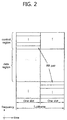
- FIG. 2 shows a structure of a UL subframe in 3GPP LTE.
- a UL subframe can be divided into a control region and a data region.
- the control region is a region to which a physical uplink control channel (PUCCH) carrying UL control information is allocated.
- a data region is a region to which a physical uplink shared channel (PUSCH) carrying user data is allocated.
- PUCCH physical uplink control channel
- PUSCH physical uplink shared channel
- the PUCCH is allocated in an RB pair in a subframe. RBs belonging to the RB pair occupy different subcarriers in each of a 1 st slot and a 2 nd slot. m is a location index indicating a logical frequency-domain location of the RB pair allocated to the PUCCH in the subframe.
- the PUSCH is allocated by a UL grant on a PDCCH.
- a 4 th OFDM symbol of each slot of a normal CP is used in transmission of a demodulation reference signal (DM RS).
- DM RS demodulation reference signal
- Uplink control information includes at least any one of HARQ ACK/NACK, channel state information (CSI), and scheduling request (SR).
- the CSI may include at least any one of a channel quality indicator (CQI) and a precoding matrix indicator (PMI).
- PUCCH formats are defined as below in order to represent combinations of UCI and PUCCH and various PUCCH transmissions.
- Table 1 PUCCH format UCI to be transmitted PUCCH format 1 Positive SR PUCCH format 1a/1b 1 bit or 2 bits HARQ ACK/NACK PUCCH format 2 CSI reporting PUCCH format 2a/2b CSI reporting and 1 bit or 2 bits HARQ ACK/NACK PUCCH format 3 HARQ ACK/NACK, SR, CSI
- a PUCCH format 3 carries 48 bits encoded UCI.
- the PUCCH format 3 may carry HARQ ACK/NACKs for a plurality of serving cells and CSI for one serving cell.
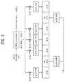
- FIG. 3 shows an example of a structure of a PUCCH format 3 in a normal CP case.
- One slot includes 7 OFDM symbols.
- I denotes an OFDM symbol number in the slot, and has a value in the range of 0 to 6.
- the symbol sequence d can be regarded as a set of modulation symbols.
- the number of bits of the UCI or a modulation scheme is for exemplary purposes only, and thus the present invention is not limited thereto.
- One PUCCH uses one RB, and one subframe includes a first slot and a second slot.
- the first sequence d1 is transmitted in the first slot
- the second sequence d2 is transmitted in the second slot.
- the first sequence d1 is transmitted in the first slot.
- the symbol sequence is spread with an orthogonal sequence w i .
- Symbol sequences are mapped to respective data OFDM symbols.
- An orthogonal sequence is used to identify a PUCCH (or UE) by spreading the symbol sequence across the data OFDM symbols.
- Two RS OFDM symbols are transmitted by mapping an RS sequence used for demodulation of UCI.
- CSI rank indicator (RI)
- HARQ ACK/NACK are coded independently
- CSI o 0 , o 1 , ..., o O-1 (where O is the number of bits of the CSI) is subjected to channel coding to generate a control information bit sequence q 0 , q 1 , ..., q NL QCQI-1 .
- N L denotes the number of layers to which a UL transport block is mapped, and
- Q CQI denotes the number of bits for each layer that can be used for the CSI.
- a (32, O) block code also referred to as a Reed-Muller (RM) code
- RM Reed-Muller
- b 0 , b 1 , ..., b 31 denote an intermediate sequence for CQI channel coding and can be generated by the following equation.
- M i,n is a basis sequence for the (32, O) block code, and may be defined as the following table.
- the control information bit sequence q 0 , q 1 , ..., q Q-1 is generated by circularly repeating the intermediate sequence b 0 , b 1 , ..., b 31 according to the following equation.
- q i b i mod 32
- i 0,1, ...,N L Q CQI- 1.
- a data bit sequence f 0 , f 1 ,..., f G-1 is multiplexed together with the CSI bit sequence into a multiplexed sequence go, g 1 , ..., g H-1 .
- the CSI may be first arranged, and thereafter a UL transport block may be arranged.
- UCI e.g., CSI
- A is the number of bits of the UCI
- M i,n is a basis sequence for a (20, A) block code, and may be defined as the following table.
- UCI e.g., RI or HARQ ACK/NACK
- A is the number of bits of the UCI
- the PUCCH format 3 may transmit up to 48 bits, but channel coding uses a basis sequence for a (32, A) block code of Table 2. Therefore, according to whether the number A of UCI bits is greater than the number of RM bases (or also referred to as a basis sequence), coding is achieved as follows. According to Table 2, the number of RM bases is 11.
- An intermediary sequence b 0 , b 1 , ..., b 31 for channel coding is generated as follows.
- M i,n is a basis sequence for the (32, 0) block code of Table 1.
- a control information bit sequence q 0 , q 1 , ..., q B-1 is generated by circularly repeating the intermediary sequence b 0 , b 1 , ..., b 31 as follows.
- q i b i mod 32
- i 0,1,... ,B-1.
- b 1 i and b 2 i Two intermediary sequences b 1 i and b 2 i are generated as follows.
- i 0,1,...,23.
- the control information bit sequence q 0 , q 1 , ..., q B-1 is obtained by concatenating the intermediary sequences.
- the CSI reporting is classified into aperiodic CSI reporting and periodic CSI reporting.
- the aperiodic CSI reporting is that a wireless device reports CSI at a request of a BS.
- the periodic CSI reporting is that the wireless device reports CSI in a periodicity predetermined by the BS.
- One or more reporting modes may be configured for the wireless device.
- reporting Type Contents Type 1 subband CQI type 1a subband CQI and second PMI Type 2/2b/2c wideband CQI and PMI Type 2a wideband PMI Type 3 RI Type 4 wideband CQI Type 5 RI and wideband PMI Type 6 RI and PTI
- the reporting mode which CSI will be reported is determined.
- Information included in the CSI is determined according to the report type in a specific reporting mode. That is, the CSI may include at least one of the followings.
- a payload size of information included in each reporting type varies as shown in the following table according to a reporting mode and a mode state.
- L> 0
- AP is an acronym of'antenna port'
- SM is an acronym of'spatial multiplexing'.
- a payload of CSI may vary for every subframe according to a transmission state and a report type. If a previously transmitted RI and/or PTI are incorrect, an error may occur between the BS and the wireless device as to a subsequent CSI payload size, which may cause a CSI decoding error or reliability deterioration.
- the number of bits of a wideband CQI/PMI currently reported is 11.
- CSI may be classified into RI CSI and non-RI CSI.
- the RI CSI denotes CSI including an RI
- non-RI denotes CSI not including the RI.
- the reporting types 1, 1a, 2, 2a, 2b, 2c, 4 of Table 5 correspond to the non-RI CSI
- the remaining reporting types correspond to the RI CSI.
- the non-RI CSI may include a CQI and/or a PMI whose value and the number of bits are determined according to an RI or a PTI.
- the CQI may include a subband CQI and/or a wideband CQI.
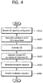
- FIG. 4 is a flowchart showing a CSI reporting method according to an embodiment of the present invention. This method may be performed by a wireless device.
- the wireless device receives a CSI reporting configuration from a BS.
- the CSI reporting configuration may include information indicating a periodicity and offset for periodic CSI reporting.
- step S420 the wireless device determines a subframe for transmitting CSI among a plurality of subframes on the basis of the CSI reporting configuration.
- the wireless device In step S430, the wireless device generates CSI for one or more serving cells according to a reporting mode.
- the CSI may include RI CSI of a 1 st serving cell and non-RI CSI of a 2 nd serving cell.
- An example of configuring a bit of the CSI for each serving cell is described below.
- the wireless device codes UCI including the CSI to generate encoded UCI.
- the UCI may further include HARQ ACK/NACK bits for one or more serving cells and/or a scheduling request (SR) bit.
- SR scheduling request
- Channel coding may include RM coding using a (32, A) block code of Table 2. Single RM or dual RM for the aforementioned PUCCH format 3 may be used. The total number of bits of the encoded UCI may be 48 bits.
- step S450 the wireless device modulates the UCI to generate a modulation sequence.
- a modulation scheme There is no restriction on a modulation scheme, and a well-known scheme such as BPSK, QPSK, 8-QAM, 16-QAM, etc., may be used.
- step S460 the wireless device transmits the modulation sequence through an uplink channel.
- the uplink channel may be a PUCCH.
- a payload size of non-RI CSI may be defined to a specific value.
- the payload size of the non-RI CSI may be fixed to 11 bits.
- a payload size of RI CSI may vary depending on a transmission state and a reporting type as shown in the example of Table 6.
- the payload size of the non-RI CSI may be pre-defined according to the number of reporting types or antenna ports.
- the following table shows an example of the payload size of the non-RI CSI according to the number of antenna ports. [Table 7] The number of antenna ports Non-RI CSI with wideband CQI Non-RI CSI with subband CQI Wideband PMI 2 8 7+L - 4 11 7+L - 8 11 11 11
- a maximum value may be selected in all reporting types.
- a payload size of CSI may be determined as a sum of a total sum of the maximum number of bits of a CQI and a total sum of the maximum number of bits of information other than the CQI.
- the total sum of the maximum number of bits of the CQI may be defined to 7.
- the information other than the CQI may be limited to a PMI. If the sum of the total sum of the maximum number of bits of the CQI and the total sum of the maximum number of bits of information other than the CQI exceeds a specific value (e.g., 11), it may be limited to the specific value.
- the following table shows an example of a payload size of non-RI CSI according to the number of antenna ports.
- Table 8 The number of antenna ports Non-RI CSI with wideband CQI Non-RI CSI with subband CQI Wideband PMI 2 9 7+L - 4 11 7+L - 8 11 11 11
- the payload size of non-RI CSI may be determined by the BS according to corresponding information.
- the determined payload size may be used as a criterion of a coding scheme and/or resource mapping, when HARQ ACK/NACK and CSI are transmitted as one piece of UCI.
- padding bits or reserved bits may be attached to the CSI to adjust a size. For example, although a payload size of non-RI CSI with a wideband CQI is set to 11 bits, if the number of bits of the wideband CQI is 8 bits, a 3-bit padding bit or reserved bit may be attached.
- the BS may decode the non-RI CSI by considering a fixed payload size.
- a Euclidean distance between code vectors may become relatively close due to a reserved bit, which may result in a deterioration of a UCI detection performance.
- a power adjustment parameter may be determined as follows.
- n CSI is a specific value (e.g., 11) in case of CSI which varies depending on a recently transmitted RI/PTI, and is the number of corresponding bits in case of CSI having a payload size fixed or predetermined according to the aforementioned embodiment (e.g., Table 7 or Table 8).
- CSI transmitted on an uplink channel may include a CSI report for one or more serving cells.
- the number of CSI reports may be limited to one or two.
- a padding bit may be attached.
- the following is a detailed example of attaching the padding bit.
- a padding bit may be attached after a least significant bit (LSB) of actual CSI.
- the actual CSI is encoded based on an RM basis having a low index.
- CSI may be divided into 2 parts, and a padding bit may be attached according to a type of the CSI.
- Information included in the CSI is divided into CQI and non-CQI (e.g., a PMI, a subband index, etc.), and a padding bit is attached to each of them.
- FIG. 5 shows an example of attaching a padding bit.
- the target number of bits of CSI is 11
- the target number of bits of a CQI is 7
- the target number of bits of a non-CQI is 4.
- the number of bits is for exemplary purposes only.
- Case (A) shows that a 3-bit padding bit is attached to a 4-bit wideband CQI, and a 2-bit padding bit is attached to a 2-bit wideband PMI.
- Case (B) shows that a 3-bit padding bit is attached to a 4-bit subband CQI, and a 3-bit padding bit is attached to a 1-bit subband index.
- Case (C) shows that 7 bits are all filled with padding bits when a CQI is absent.
- transmit power P PUCCH (i) for PUCCH transmission at a subframe i is defined as follows.
- P PUCCH i min P CMAX , P 0 _PUCCH + PL + h n CQI n HARQ n SR + ⁇ F_PUCCH F + ⁇ T ⁇ D F ′ + g i
- P PUCCH i min P CMAX , P 0 _PUCCH + PL + h n CQI n HARQ n SR + ⁇ F_PUCCH F + ⁇ T ⁇ D F ′ + g i
- h(n CQI , n HARQ , n SR ) is determined as follows.
- the UCI of the PUCCH format 3 may include HARQ ACK/NACK and CSI.
- an error rate requirement for the HARQ ACK/NACK is set to be higher than a block error rate requirement for the CSI. For example, it is known that a probability that HARQ NACK is incorrectly detected as HARQ ACK is set to be less than 10 -3 , and a block error rate for the CSI is set to be less than 10 -2 .
- the UCI includes a bit sequence which is not yet encoded and which is transmitted on an uplink channel (e.g., a PUCCH format 3).
- the UCI may include HARQ ACK/NACK for one or more serving cells and/or CSI for one or more serving cells.
- the embodiment of FIG. 4 may be applied.
- the UCI includes only the HARQ ACK/NACK, it is called UCI1. If the UCI includes both the HARQ ACK/NACK and the CSI, it is called UCI2. If the UCI includes only the CSI, it is called UCI3.
- the UCI1 includes only HARQ ACK/NACK
- transmit power may be controlled on the basis of a case where an error protection level for entire information bits is lowest.
- the UCI2 includes HARQ ACK/NACK and CSI
- the transmit power may be controlled on the basis of a case where the error protection level for an information bit corresponding to the HARQ ACK/NACK is lowest.
- the transmit power saving may be increased.
- transmit power of a PUCCH is dependent on a function h(n CQI , N HARQ , n SR ) of an information bit of UCI.
- a required signal-to-noise ratio (SNR) for satisfying an error requirement may be lower in the UCI3 than in the UCI1 and the UCI2.
- P may be a parameter obtained on the basis of a required SNR of the UCI1 and a required SNR of the UCI3.
- ⁇ may be defined based on a difference value between the required SNR of the UCI1 and the required SNR of the UCI3.
- h(n CQI , n HARQ , n SR ) may be determined as follows.
- the PUCCH format 3 may also be transmitted together with a sounding reference signal (SRS) in one subframe.
- SRS sounding reference signal
- a code rate difference between the normal PUCCH format 3 and the shortened PUCCH format is increased linearly.
- a required SNR for satisfying an error requirement of the UCI may be increased. Therefore, the shortened PUCCH format requires a more accurate power control than the normal PUCCH format 3.
- P PUCCH (i) transmit power P PUCCH (i) for PUCCH transmission at a subframe i according to an exemplary embodiment of the present invention.
- P PUCCH i min P CMAX , P 0 _PUCCH + PL + h n CQI n HARQ n SR + ⁇ F_PUCCH F + ⁇ T ⁇ D F ′ + g i + ⁇ s F "
- ⁇ s (F) is an offset parameter for a shortened PUCCH format.
- PUCCH transmission power may be acquired as follows.
- P PUCCH i min P CMAX , P 0 _PUCCH + PL + h ′ n CQI n HARQ n SR + ⁇ F_PUCCH F + ⁇ T ⁇ D F ′ + g i
- h'(n CQI , n HARQ , n SR ) may be determined by Equation 16 or Equation 17 below.
- ⁇ may be set to a value predefined or given by the BS.
- h'(n CQI , n HARQ , n SR ) may be the same as in the existing 3GPP LTE, or may be defined by Equation 11 to Equation 13.
- the modified transmit power may be applied in all subframes in which a shortened PUCCH format is transmitted or a subframe in which the shortened PUCCH format is transmitted for periodic CSI. Whether to apply the modified transmit power may be reported by the BS to the wireless device.
- FIG. 6 is a block diagram of a wireless device according to an embodiment of the present invention.
- a wireless device 50 includes a processor 51, a memory 52, and a radio frequency (RF) unit 53.
- RF radio frequency
- the memory 52 is coupled with the processor 51, and stores instructions executed by the processor 51.
- an instruction for executing the software may be stored in the memory 52.
- the RF unit 53 is coupled with the processor 51, and transmits and/or receives a radio signal.
- UCI may be transmitted on a PUCCH or a PUSCH by the RF unit 53.
- the processor 51 implements the proposed functions, procedures, and/or methods. In the aforementioned embodiment, an operation of the wireless device 50 may be implemented by the processor 51.
- the processor may include an application-specific integrated circuit (ASIC), a separate chipset, a logic circuit, and/or a data processing unit.
- the memory may include a read-only memory (ROM), a random access memory (RAM), a flash memory, a memory card, a storage medium, and/or other equivalent storage devices.
- the RF unit may include a base-band circuit for processing a radio signal.
- the aforementioned methods can be implemented with a module (i.e., process, function, etc.) for performing the aforementioned functions.
- the module may be stored in the memory and may be performed by the processor.
- the memory may be located inside or outside the processor, and may be coupled to the processor by using various well-known means.
Description
- The present invention relates to wireless communications, and more particularly, to a method and apparatus for reporting channel state information in a wireless communication system.
- 3rd generation partnership project (3GPP) long term evolution (LTE) evolved from a universal mobile telecommunications system (UMTS) is introduced as the 3GPP release 8. The 3GPP LTE uses orthogonal frequency division multiple access (OFDMA) in a downlink, and uses single carrier-frequency division multiple access (SC-FDMA) in an uplink. The 3GPP LTE employs multiple input multiple output (MIMO) having up to four antennas. In recent years, there is an ongoing discussion on 3GPP LTE-advanced (LTE-A) evolved from the 3GPP LTE.
- As disclosed in 3GPP TS 36.211 V10.4.0 (2011-12) "Evolved Universal Terrestrial Radio Access (E-UTRA); Physical Channels and Modulation (Release 10)", a physical channel of the LTE can be classified into a downlink channel, i.e., a physical downlink shared channel (PDSCH) and a physical downlink control channel (PDCCH), and an uplink channel, i.e., a physical uplink shared channel (PUSCH) and a physical uplink control channel (PUCCH).
- The uplink channel is used to transmit a variety of uplink control information such as hybrid automatic repeat request (HARQ) positive-acknowledgement (ACK)/negative-acknowledgement (NACK), channel state information (CSI), and scheduling request (SR).
- With the introduction of a scheme of increasing channel capacity such as multiple input multiple output (MIMO) and carrier aggregation (CA), an amount of uplink control information is also increased. A radio resource for an uplink channel may be more restrictive than a radio resource for a downlink channel, and a transmission error of the uplink control information may aggravate service quality.
US 2011/0 249 643 discloses techniques for periodically reporting CSI on protected and unprotected resources. - There is a need to design a coding and power control for an uplink channel according to an increasing amount of the uplink control information.
- The present invention provides a method of reporting channel state information and a wireless device using the method.
- In an aspect, a method of reporting channel state information (CSI) in a wireless communication system is provided. The method includes receiving a configuration for CSI reporting, the configuration including a periodicity and an offset, determining a subframe in which the CSI is reported among a plurality of subframes according to the configuration, generating the CSI, coding uplink control information (UCI) containing the CSI to generate encoded UCI, modulating the encoded UCI to generate a modulation sequence, and transmitting the modulation sequence in the determined subframe on an uplink channel. If the CSI includes a rank indicator (RI), a payload size of the CSI is determined according to the RI. If the CSI does not include the RI, the payload size of the CSI is fixed.
- If the CSI does not include the RI, the CSI may include at least one padding bit.
- If the CSI does not include the RI, the CSI may include a channel quality indicator (CQI) and a precoding matrix indicator (PMI).
- The at least one padding bit may be attached to a least significant bit (LSB) of the CSI.
- The at least one padding bit may include a first padding bit and a second padding bit. The first padding bit may be attached to the CQI, and the second padding bit may be attached to the PMI.
- In another aspect, a wireless device for reporting channel state information (CSI) in a wireless communication system includes a memory, and a processor operatively coupled to the memory. The processor is configured to receive a configuration for CSI reporting, the configuration including a periodicity and an offset, determine a subframe in which the CSI is reported among a plurality of subframes according to the configuration, generate the CSI, code uplink control information (UCI) containing the CSI to generate encoded UCI, modulate the encoded UCI to generate a modulation sequence, and transmit the modulation sequence in the determined subframe on an uplink channel. If the CSI includes a rank indicator (RI), a payload size of the CSI is determined according to the RI. If the CSI does not include the RI, the payload size of the CSI is fixed.
- A variety of types and an increased amount of uplink control information can be transmitted, and a transmission error can be decreased.
-
-
FIG. 1 shows a structure of a downlink (DL) radio frame in 3rd generation partnership project (3GPP) long term evolution (LTE). -
FIG. 2 shows a structure of an uplink (UL) subframe in 3GPP LTE. -
FIG. 3 shows an example of a structure of a physical uplink control channel (PUCCH)format 3 in a normal cyclic prefix (CP) case. -
FIG. 4 is a flowchart showing a channel state information (CSI) reporting method according to an embodiment of the present invention. -
FIG. 5 shows an example of attaching a padding bit. -
FIG. 6 is a block diagram of a wireless device according to an embodiment of the present invention. - A wireless device may be fixed or mobile, and may be referred to as another terminology, such as a user equipment (UE), a mobile station (MS), a user terminal (UT), a subscriber station (SS), a mobile terminal (MT), etc. A base station (BS) is generally a fixed station that communicates with the wireless device and may be referred to as another terminology, such as an evolved node-B (eNB), a base transceiver system (BTS), an access point, etc.
- Hereinafter, the present invention is applied based on a 3rd generation partnership project (3GPP) long term evolution (LTE) or a 3GPP LTE-Advanced (LTE-A). This is for exemplary purposes only, and thus the present invention is applicable to various communication systems. In the following description, LTE and/or LTE-A are collectively referred to as LTE.
- The wireless device may be served by a plurality of serving cells. Each serving cell may be defined with a downlink (DL) component carrier (CC) or a pair of a DL CC and an uplink (UL) CC.
- The serving cell may be classified into a primary cell and a secondary cell. The primary cell operates at a primary frequency, and is a cell designated as the primary cell when an initial network entry process is performed or when a network re-entry process starts or in a handover process. The primary cell is also called a reference cell. The secondary cell operates at a secondary frequency. The secondary cell may be configured after a radio resource control (RRC) connection is established, and may be used to provide an additional radio resource. At least one primary cell is configured always. The secondary cell may be added/modified/released by using higher-layer signaling (e.g., an RRC message).
- A cell index (CI) of the primary cell may be fixed. For example, a lowest CI may be designated as a CI of the primary cell. It is assumed hereinafter that the CI of the primary cell is 0 and a CI of the secondary cell is allocated sequentially starting from 1.
-
FIG. 1 shows a structure of a DL radio frame in 3GPP LTE. Reference is made to thesection 4 of 3GPP TS 36.211 V10.4.0 (2011-12) "Evolved Universal Terrestrial Radio Access (E-UTRA), Physical Channels and Modulation (Release 10)".". - A radio frame includes 10 subframes indexed with 0 to 9. One subframe includes 2 consecutive slots. A time required for transmitting one subframe is defined as a transmission time interval (TTI). For example, one subframe may have a length of 1 millisecond (ms), and one slot may have a length of 0.5 ms.
- One slot may include a plurality of orthogonal frequency division multiplexing (OFDM) symbols in a time domain. Since the 3GPP LTE uses orthogonal frequency division multiple access (OFDMA) in a downlink (DL), the OFDM symbol is only for expressing one symbol period in the time domain, and there is no limitation in a multiple access scheme or terminologies. For example, the OFDM symbol may also be referred to as another terminology such as a single carrier frequency division multiple access (SC-FDMA) symbol, a symbol period, etc.
- Although it is described that one slot includes 7 OFDM symbols for example, the number of OFDM symbols included in one slot may vary depending on a length of a cyclic prefix (CP). According to 3GPP TS 36.211 V10.4.0, in case of a normal CP, one slot includes 7 OFDM symbols, and in case of an extended CP, one slot includes 6 OFDM symbols.
- A resource block (RB) is a resource allocation unit, and includes a plurality of subcarriers in one slot. For example, if one slot includes 7 OFDM symbols in a time domain and the RB includes 12 subcarriers in a frequency domain, one RB can include 7x 12 resource elements (REs).
- A DL subframe is divided into a control region and a data region in the time domain. The control region includes up to first four OFDM symbols of a first slot in the subframe. However, the number of OFDM symbols included in the control region may vary. A physical downlink control channel (PDCCH) and other control channels are allocated to the control region, and a physical downlink shared channel (PDSCH) is allocated to the data region.
- As described in 3GPP TS 36.211 V10.4.0, in 3GPP LTE, a physical channel may be divided into a data channel and a control channel. The data channel may be a physical downlink shared channel (PDSCH) and a physical uplink shared channel (PUSCH). The control channel may be a physical downlink control channel (PDCCH), a physical control format indicator channel (PCFICH), a physical hybrid-ARQ indicator channel (PHICH), and a physical uplink control channel (PUCCH).
- The PCFICH transmitted in a first OFDM symbol of the subframe carries a control format indicator (CFI) regarding the number of OFDM symbols (i.e., a size of the control region) used for transmission of control channels in the subframe. A wireless device first receives the CFI on the PCFICH, and thereafter monitors the PDCCH.
- Unlike the PDCCH, the PCFICH does not use blind decoding, and is transmitted by using a fixed PCFICH resource of the subframe.
- The PHICH carries a positive-acknowledgement (ACK)/negative-acknowledgement (NACK) signal for an uplink hybrid automatic repeat request (HARQ). The ACK/NACK signal for uplink (UL) data on a PUSCH transmitted by the wireless device is transmitted on the PHICH.
- A physical broadcast channel (PBCH) is transmitted in first four OFDM symbols in a second slot of a first subframe of a radio frame. The PBCH carries system information necessary for communication between the wireless device and a BS. The system information transmitted through the PBCH is referred to as a master information block (MIB). In comparison thereto, system information transmitted on the PDCCH is referred to as a system information block (SIB).
- Control information transmitted through the PDCCH is referred to as downlink control information (DCI). The DCI may include resource allocation of the PDSCH (this is referred to as a downlink (DL) grant), resource allocation of a PUSCH (this is referred to as an uplink (UL) grant), a set of transmit power control commands for individual UEs in any UE group, and/or activation of a voice over Internet protocol (VoIP).
- In 3GPP LTE, blind decoding is used to detect a PDCCH. The blind decoding is a scheme in which a desired identifier is de-masked from a cyclic redundancy check (CRC) of a received PDCCH (referred to as a candidate PDCCH) to determine whether the PDCCH is its own control channel by performing CRC error checking. A BS determines a PDCCH format according to DCI to be transmitted to a wireless device, attaches a cyclic redundancy check (CRC) to control information, and masks a unique identifier (referred to as a radio network temporary identifier (RNTI)) to the CRC according to an owner or usage of the PDCCH.
- According to 3GPP TS 36.211 V10.4.0, an uplink channel includes a PUSCH, a PUCCH, a sounding reference signal (SRS), and a physical random access channel (PRACH).
-
FIG. 2 shows a structure of a UL subframe in 3GPP LTE. - A UL subframe can be divided into a control region and a data region. The control region is a region to which a physical uplink control channel (PUCCH) carrying UL control information is allocated. A data region is a region to which a physical uplink shared channel (PUSCH) carrying user data is allocated.
- The PUCCH is allocated in an RB pair in a subframe. RBs belonging to the RB pair occupy different subcarriers in each of a 1st slot and a 2nd slot. m is a location index indicating a logical frequency-domain location of the RB pair allocated to the PUCCH in the subframe.
- It shows that RBs having the same value m occupy different subcarriers in the two slots.
- The PUSCH is allocated by a UL grant on a PDCCH. Although not shown, a 4th OFDM symbol of each slot of a normal CP is used in transmission of a demodulation reference signal (DM RS).
- Uplink control information (UCI) includes at least any one of HARQ ACK/NACK, channel state information (CSI), and scheduling request (SR). Hereinafter, as an index of indicating a state of a DL channel, the CSI may include at least any one of a channel quality indicator (CQI) and a precoding matrix indicator (PMI).
- PUCCH formats are defined as below in order to represent combinations of UCI and PUCCH and various PUCCH transmissions.
[Table 1] PUCCH format UCI to be transmitted PUCCH format 1Positive SR PUCCH format 1a/ 1b 1 bit or 2 bits HARQ ACK/ NACK PUCCH format 2 CSI reporting PUCCH format 2a/2b CSI reporting and 1 bit or 2 bits HARQ ACK/ NACK PUCCH format 3 HARQ ACK/NACK, SR, CSI - A
PUCCH format 3 carries 48 bits encoded UCI. ThePUCCH format 3 may carry HARQ ACK/NACKs for a plurality of serving cells and CSI for one serving cell. -
FIG. 3 shows an example of a structure of aPUCCH format 3 in a normal CP case. - One slot includes 7 OFDM symbols. I denotes an OFDM symbol number in the slot, and has a value in the range of 0 to 6. Two OFDM symbols with l=1, 5 are used as RS OFDM symbols for a reference signal, and the remaining OFDM symbols are used as data OFDM symbols for a UCI signal.
- A symbol sequence d={d(0), d(1), ..., d(23)} is generated by performing QPSK modulation on a 48-bit encoded UCI (e.g., encoded ACK/NACK). d(n)( n=0,1,...,23) is a complex-valued modulation symbol. The symbol sequence d can be regarded as a set of modulation symbols. The number of bits of the UCI or a modulation scheme is for exemplary purposes only, and thus the present invention is not limited thereto.
- One PUCCH uses one RB, and one subframe includes a first slot and a second slot. A symbol sequence d={d(0), d(1), ..., d(23)} is divided into two sequences d1={d(0),..., d(11)} and d2={d(12),...,d(23)}, each having a length of 12. The first sequence d1 is transmitted in the first slot, and the second sequence d2 is transmitted in the second slot. In
FIG. 4 , the first sequence d1 is transmitted in the first slot. - The symbol sequence is spread with an orthogonal sequence wi. Symbol sequences are mapped to respective data OFDM symbols. An orthogonal sequence is used to identify a PUCCH (or UE) by spreading the symbol sequence across the data OFDM symbols.
- Two RS OFDM symbols are transmitted by mapping an RS sequence used for demodulation of UCI.
- Now, UCI coding in 3GPP LTE is described with reference to the
section 5 of 3GPP TS 36.212 V10.4.0 (2011-12) "Evolved Universal Terrestrial Radio Access (E-UTRA); Multiplexing and channel coding (Release 10)". - CSI, rank indicator (RI), and HARQ ACK/NACK are coded independently
- First, CSI coding for a PUSCH is described.
- CSI o0, o1, ..., oO-1 (where O is the number of bits of the CSI) is subjected to channel coding to generate a control information bit sequence q0, q1, ..., qNL QCQI-1. NL denotes the number of layers to which a UL transport block is mapped, and QCQI denotes the number of bits for each layer that can be used for the CSI.
- For example, a (32, O) block code (also referred to as a Reed-Muller (RM) code) may be used as channel coding for the CSI.
- b0, b1, ..., b31 denote an intermediate sequence for CQI channel coding and can be generated by the following equation.

- Herein, i=0,1,...,31. Mi,n is a basis sequence for the (32, O) block code, and may be defined as the following table.
[Table 2] i Mi,0 Mi,1 Mi,2 Mi,3 Mi,4 Mi.5 Mi,6 Mi,7 Mi,8 Mi.9 Mi.10 0 1 1 0 0 0 0 0 0 0 0 1 1 1 1 1 0 0 0 0 0 0 1 1 2 1 0 0 1 0 0 1 0 1 1 1 3 1 0 1 1 0 0 0 0 1 0 1 4 1 1 1 1 0 0 0 1 0 0 1 5 1 1 0 0 1 0 1 1 1 0 1 6 1 0 1 0 1 0 1 0 1 1 1 7 1 0 0 1 1 0 0 1 1 0 1 8 1 1 0 1 1 0 0 1 0 1 1 9 1 0 1 1 1 0 1 0 0 1 1 10 1 0 1 0 0 1 1 1 0 1 1 11 1 1 1 0 0 1 1 0 1 0 1 12 1 0 0 1 0 1 0 1 1 1 1 13 1 1 0 1 0 1 0 1 0 1 1 14 1 0 0 0 1 1 0 1 0 0 1 15 1 1 0 0 1 1 1 1 0 1 1 16 1 1 1 0 1 1 1 0 0 1 0 17 1 0 0 1 1 1 0 0 1 0 0 18 1 1 0 1 1 1 1 1 0 0 0 19 1 0 0 0 0 1 1 0 0 0 0 20 1 0 1 0 0 0 1 0 0 0 1 21 1 1 0 1 0 0 0 0 0 1 1 22 1 0 0 0 1 0 0 1 1 0 1 23 1 1 1 0 1 0 0 0 1 1 1 24 1 1 1 1 1 0 1 1 1 1 0 25 1 1 0 0 0 1 1 1 0 0 1 26 1 0 1 1 0 1 0 0 1 1 0 27 1 1 1 1 0 1 0 1 1 1 0 28 1 0 1 0 1 1 1 0 1 0 0 29 1 0 1 1 1 1 1 1 1 0 0 30 1 1 1 1 1 1 1 1 1 1 1 31 1 0 0 0 0 0 0 0 0 0 0 - The control information bit sequence q0, q1, ..., qQ-1 is generated by circularly repeating the intermediate sequence b0, b1, ..., b31 according to the following equation.

- Herein, i=0,1, ...,NLQCQI-1.
- A data bit sequence f0, f1,..., fG-1 is multiplexed together with the CSI bit sequence into a multiplexed sequence go, g1, ..., gH-1. In the multiplexed symbol sequence, the CSI may be first arranged, and thereafter a UL transport block may be arranged. H denotes the total number of bits allocated to the PUSCH, and is defined as H=G+NLQCQI. Herein, q; is a modulation symbol on constellation, and H'=H/Qm. Qm denotes the number of bits for each modulation symbol of a modulation scheme. For example, when quadrature phase shift keying (QPSK) is used as the modulation scheme, Qm=2.
- Now, CSI coding for a
PUCCH format 2 is described. - UCI (e.g., CSI) u0, u1,..., uA-1 (where A is the number of bits of the UCI) is subjected to channel coding to generate an encoded bit sequence b0, b1, ..., bB-1. B is the number of bits capable of transmitting a corresponding PUCCH. Since the
PUCCH format 2 can transmit 20-bit coded UCI, B=20. - A (20, A) block code (or also referred to as a Reed-Muller (RM) code) may be used as channel coding for the
PUCCH format 2. This can be expressed as follows.
- Herein, i=0,1,...,B-1. Mi,n is a basis sequence for a (20, A) block code, and may be defined as the following table.
[Table 3] i Mi,0 Mi,1 Mi,2 Mi,3 Mi,4 Mi.5 Mi,6 Mi,7 Mi,8 Mi,9 Mi,10 Mi,11 Mi,12 0 1 1 0 0 0 0 0 0 0 0 1 1 0 1 1 1 1 0 0 0 0 0 0 1 1 1 0 2 1 0 0 1 0 0 1 0 1 1 1 1 1 3 1 0 1 1 0 0 0 0 1 0 1 1 1 4 1 1 1 1 0 0 0 1 0 0 1 1 1 5 1 1 0 0 1 0 1 1 1 0 1 1 1 6 1 0 1 0 1 0 1 0 1 1 1 1 1 7 1 0 0 1 1 0 0 1 1 0 1 1 1 8 1 1 0 1 1 0 0 1 0 1 1 1 1 9 1 0 1 1 1 0 1 0 0 1 1 1 1 10 1 0 1 0 0 1 1 1 0 1 1 1 1 11 1 1 1 0 0 1 1 0 1 0 1 1 1 12 1 0 0 1 0 1 0 1 1 1 1 1 1 13 1 1 0 1 0 1 0 1 0 1 1 1 1 14 1 0 0 0 1 1 0 1 0 0 1 0 1 15 1 1 0 0 1 1 1 1 0 1 1 0 I 16 1 1 1 0 1 1 1 0 0 1 0 1 1 17 1 0 0 1 1 1 0 0 1 0 0 1 1 18 1 1 0 1 1 1 1 1 0 0 0 0 0 19 1 0 0 0 0 1 1 0 0 0 0 0 0 - Now, RI or HARQ ACK/NACK coding is described.
- UCI (e.g., RI or HARQ ACK/NACK) u0, u1, ..., uA-1 (where A is the number of bits of the UCI) is subjected to channel coding to generate an encoded bit sequence qo, q1, ..., qB-1. B is the number of bits capable of transmitting a corresponding PUCCH. Since the
PUCCH format 3 can transmit coded UCI of 48 bits, B=48. - The
PUCCH format 3 may transmit up to 48 bits, but channel coding uses a basis sequence for a (32, A) block code of Table 2. Therefore, according to whether the number A of UCI bits is greater than the number of RM bases (or also referred to as a basis sequence), coding is achieved as follows. According to Table 2, the number of RM bases is 11. - If A <= 11, the following is satisfied.
- An intermediary sequence b0, b1, ..., b31 for channel coding is generated as follows.

- Herein, i=0,1,...,31, and Mi,n is a basis sequence for the (32, 0) block code of Table 1.
- A control information bit sequence q0, q1, ..., qB-1 is generated by circularly repeating the intermediary sequence b0, b1, ..., b31 as follows.

- Herein, i=0,1,... ,B-1.
- If 11 < A <= 21, the following is satisfied.
- Two intermediary sequences b1 i and b2 i are generated as follows.

- Herein, i=0,1,...,23.
- The control information bit sequence q0, q1, ..., qB-1 is obtained by concatenating the intermediary sequences.

- If A <=1 11, since one RM block code (or one RM encoder) is used, this is called single RM. If A > 11, since two RM block codes (or two RM encoders) are used, this is called dual RM.
- Now, CSI reporting in 3GPP LTE is described with reference to the section 7.2 of 3GPP TS 36.213 V10.4.0 (2011-12) "Evolved Universal Terrestrial Radio Access (E-UTRA); Physical layer procedures (Release 10)".
- The CSI reporting is classified into aperiodic CSI reporting and periodic CSI reporting. The aperiodic CSI reporting is that a wireless device reports CSI at a request of a BS. The periodic CSI reporting is that the wireless device reports CSI in a periodicity predetermined by the BS.
- Since various transmission modes such as single antenna transmission, multiple antenna transmission, etc., are supported by the wireless device, various CSI reporting modes are provided. The following table is an example of a reporting mode for periodic CSI reporting.
[Table 4] PMI Feedback Type PMI Feedback Type NoPMI No PMI Wideband CQI Mode 1-0 Mode 1-0 subband CQI Mode 2-0 Mode 2-0 - One or more reporting modes may be configured for the wireless device.
- In addition to the reporting mode, a reporting type shown in the following table is also defined.
[Table 5] Reporting Type Contents Type 1 subband CQI type 1a subband CQI and second PMI Type 2/2b/2c wideband CQI and PMI Type 2a wideband PMI Type 3 RI Type 4 wideband CQI Type 5 RI and wideband PMI Type 6 RI and PTI - In the reporting mode, which CSI will be reported is determined. Information included in the CSI is determined according to the report type in a specific reporting mode. That is, the CSI may include at least one of the followings.
- Rank indicator (RI)
- Subband CQI: A CQI for any one of S (S>1) subbands. A size of the subband may vary depending on a size of a system band.
- Wideband CQI: A CQI for S subbands.
- Wideband PMI: A PMI for S subbands.
- Precoding type indicator (PTI): Type for a PMI.
- A payload size of information included in each reporting type varies as shown in the following table according to a reporting mode and a mode state. Herein, L>=0, and AP is an acronym of'antenna port', and SM is an acronym of'spatial multiplexing'.
[Table 6] Repor ting Type Reported Mode State Reporting Modes Mode1-1 (bits/BP) Mode2-1 (bits/BP) Mode1-0 (bits/BP) Mode2-0 (bits/BP) 1 Subband CQI RI = 1 NA 4+L NA 4+L RI > 1 NA 7+L NA 4+L 1a Subband CQI / second PMI 8 APs RI = 1 NA 8+L NA NA 8 APs 1 < RI < 5 NA 9+L NA NA 8 APs RI > 4 NA 7+L NA NA 2 Wideband CQI/PMI 2 APs RI = 1 6 6 NA NA 4 APs RI = 1 8 8 NA NA 2 APs RI > 1 8 8 NA NA 4 APs RI > 1 11 11 NA NA 2a Wideband first PMI 8 APs RI < 3 NA 4 NA NA 8 APs 2 < RI < 8 NA 2 NA NA 8 APs RI = 8 NA 0 NA NA 2b Wideband CQI / second PMI 8 APs RI = 1 8 8 NA NA 8 APs 1 < RI < 4 11 11 NA NA 8 APs RI = 4 10 10 NA NA 8 APs RI > 4 7 7 NA NA 2c Wideband CQI / first PMI / second PMI 8 APs RI = 1 8 NA NA NA 8 APs 1 < RI ≤ 4 11 NA NA NA 8 APs 4 < RI < 7 9 NA NA NA 8 APs RI = 8 7 NA NA NA 3 RI 2/4 APs, 2-layer SM 1 1 1 1 8 APs, 2-layer SM 1 NA NA NA 4 APs 4-layer SM 2 2 2 2 8 APs, 4-layer SM 2 NA NA NA 8-layer SM 3 NA NA NA 4 Wideband RI = 1 or RI>1 NA NA 4 4 5 RI/ first PMI 8 APs, 2-layers 4 NA NA NA 8 APs, 4 and 8-layer SM 5 6 RI/PTI 8 APs, 2-layer SM NA 2 NA NA 8 APs, 4-layer SM NA 3 NA NA 8 APs, 8-layer SM NA 4 NA NA - Accordingly, when periodic CSI is sent, a payload of CSI may vary for every subframe according to a transmission state and a report type. If a previously transmitted RI and/or PTI are incorrect, an error may occur between the BS and the wireless device as to a subsequent CSI payload size, which may cause a CSI decoding error or reliability deterioration.
- For example, it is assumed that RI=2 is previously reported when the mode 2-1 and the 8 APs are configured. According to Table 6, the number of bits of a wideband CQI/PMI currently reported is 11. However, if the BS fails to receive RI=2 previously reported, the BS does not exactly know the number of bits of the wideband CQI/PMI currently reported.
- Hereinafter, a method of decreasing a reception error of UCI is proposed according to an embodiment of the present invention.
- CSI may be classified into RI CSI and non-RI CSI. The RI CSI denotes CSI including an RI, and non-RI denotes CSI not including the RI. For example, the
reporting types - The non-RI CSI may include a CQI and/or a PMI whose value and the number of bits are determined according to an RI or a PTI. The CQI may include a subband CQI and/or a wideband CQI.
-
FIG. 4 is a flowchart showing a CSI reporting method according to an embodiment of the present invention. This method may be performed by a wireless device. - In step S410, the wireless device receives a CSI reporting configuration from a BS. The CSI reporting configuration may include information indicating a periodicity and offset for periodic CSI reporting.
- In step S420, the wireless device determines a subframe for transmitting CSI among a plurality of subframes on the basis of the CSI reporting configuration.
- In step S430, the wireless device generates CSI for one or more serving cells according to a reporting mode. For example, the CSI may include RI CSI of a 1st serving cell and non-RI CSI of a 2nd serving cell. An example of configuring a bit of the CSI for each serving cell is described below.
- In step S440, the wireless device codes UCI including the CSI to generate encoded UCI. The UCI may further include HARQ ACK/NACK bits for one or more serving cells and/or a scheduling request (SR) bit.
- Channel coding may include RM coding using a (32, A) block code of Table 2. Single RM or dual RM for the
aforementioned PUCCH format 3 may be used. The total number of bits of the encoded UCI may be 48 bits. - In step S450, the wireless device modulates the UCI to generate a modulation sequence. There is no restriction on a modulation scheme, and a well-known scheme such as BPSK, QPSK, 8-QAM, 16-QAM, etc., may be used.
- In step S460, the wireless device transmits the modulation sequence through an uplink channel. The uplink channel may be a PUCCH.
- Now, an example of configuring bits of CSI is described.
- In one embodiment, a payload size of non-RI CSI may be defined to a specific value. For example, the payload size of the non-RI CSI may be fixed to 11 bits. A payload size of RI CSI may vary depending on a transmission state and a reporting type as shown in the example of Table 6.
- In another embodiment, the payload size of the non-RI CSI may be pre-defined according to the number of reporting types or antenna ports. The following table shows an example of the payload size of the non-RI CSI according to the number of antenna ports.
[Table 7] The number of antenna ports Non-RI CSI with wideband CQI Non-RI CSI with subband CQI Wideband PMI 2 8 7+L - 4 11 7+L - 8 11 11 11 - For each piece of CSI, a maximum value may be selected in all reporting types.
- In another embodiment, a payload size of CSI may be determined as a sum of a total sum of the maximum number of bits of a CQI and a total sum of the maximum number of bits of information other than the CQI. The total sum of the maximum number of bits of the CQI may be defined to 7. In addition, the information other than the CQI may be limited to a PMI. If the sum of the total sum of the maximum number of bits of the CQI and the total sum of the maximum number of bits of information other than the CQI exceeds a specific value (e.g., 11), it may be limited to the specific value.
- The following table shows an example of a payload size of non-RI CSI according to the number of antenna ports.
[Table 8] The number of antenna ports Non-RI CSI with wideband CQI Non-RI CSI with subband CQI Wideband PMI 2 9 7+L - 4 11 7+L - 8 11 11 11 - The payload size of non-RI CSI may be determined by the BS according to corresponding information.
- The determined payload size may be used as a criterion of a coding scheme and/or resource mapping, when HARQ ACK/NACK and CSI are transmitted as one piece of UCI.
- If the payload size is fixed as shown in Table 7 or Table 8 above, and if the number of bits of corresponding CSI is small, padding bits or reserved bits may be attached to the CSI to adjust a size. For example, although a payload size of non-RI CSI with a wideband CQI is set to 11 bits, if the number of bits of the wideband CQI is 8 bits, a 3-bit padding bit or reserved bit may be attached.
- The BS may decode the non-RI CSI by considering a fixed payload size. In this case, a Euclidean distance between code vectors may become relatively close due to a reserved bit, which may result in a deterioration of a UCI detection performance. To reduce this, a power adjustment parameter may be determined as follows.
- If the transmit diversity is not applied or the number of bits of information to be encoded is less than or equal to 11, the power adjustment parameter is as follows.

- If the transmit diversity is applied or the number of bits of information to be encoded is greater than 11, the power adjustment parameter is as follows.

- In Equations 8 and 9, nCSI is a specific value (e.g., 11) in case of CSI which varies depending on a recently transmitted RI/PTI, and is the number of corresponding bits in case of CSI having a payload size fixed or predetermined according to the aforementioned embodiment (e.g., Table 7 or Table 8).
- CSI transmitted on an uplink channel may include a CSI report for one or more serving cells. In this case, the number of CSI reports may be limited to one or two.
- As described above, if the number of bits of actual CSI is less than the target number of bits, a padding bit may be attached. The following is a detailed example of attaching the padding bit.
- In one embodiment, a padding bit may be attached after a least significant bit (LSB) of actual CSI. The actual CSI is encoded based on an RM basis having a low index.
- In another embodiment, CSI may be divided into 2 parts, and a padding bit may be attached according to a type of the CSI. Information included in the CSI is divided into CQI and non-CQI (e.g., a PMI, a subband index, etc.), and a padding bit is attached to each of them.
-
FIG. 5 shows an example of attaching a padding bit. - It is assumed that the target number of bits of CSI is 11, the target number of bits of a CQI is 7, and the target number of bits of a non-CQI is 4. The number of bits is for exemplary purposes only.
- Case (A) shows that a 3-bit padding bit is attached to a 4-bit wideband CQI, and a 2-bit padding bit is attached to a 2-bit wideband PMI.
- Case (B) shows that a 3-bit padding bit is attached to a 4-bit subband CQI, and a 3-bit padding bit is attached to a 1-bit subband index.
- Case (C) shows that 7 bits are all filled with padding bits when a CQI is absent.
- Now, a power control of an uplink channel is described according to an embodiment of the present invention.
- Referring to the
section 5 of 3GPP TS 36.213 V10.4.0, transmit power PPUCCH(i) for PUCCH transmission at a subframe i is defined as follows.
Herein, - PCMAX is transmit power configured for a UE,
- PO_PUCCH(j) is a parameter determined as a sum of PO_NOMINAL_PUCCH(j) which is a cell-specific element given by a higher layer and PO_UE_PUCCH(j) which is a UE-specific element,
- PL is a DL pathloss estimation calculated by a wireless device,
- h(nCQI, nHARQ, nSR) is a value dependent on a PUCCH format, where nCQI is the number of bits of CSI, nHARQ is the number of bits of HARQ ACK/NACK, and nSR is the number of bits of SR,
- ΔF_UCCH(F) is a parameter given by the higher layer,
- ΔTxD(F') is a parameter given by the higher layer, and
- g(i) is a UE-specific value acquired from TPC.
- More specifically, h(nCQI, nHARQ, nSR) is determined as follows.
- i) For a
PUCCH format 3 without periodic CSI reporting,
if thePUCCH format 3 is configured with 2-antenna port transmission or if UCI is greater than 11,

otherwise,

- ii) For a
PUCCH format 3 with periodic CSI reporting,
if thePUCCH format 3 is configured with 2-antenna port transmission or if UCI is greater than 11,

otherwise,

- The UCI of the
PUCCH format 3 may include HARQ ACK/NACK and CSI. In general, an error rate requirement for the HARQ ACK/NACK is set to be higher than a block error rate requirement for the CSI. For example, it is known that a probability that HARQ NACK is incorrectly detected as HARQ ACK is set to be less than 10-3, and a block error rate for the CSI is set to be less than 10-2. - It is proposed to control transmit power by considering various error rate requirements when UCI having two or more types of information is transmitted on one uplink channel.
- Hereinafter, the UCI includes a bit sequence which is not yet encoded and which is transmitted on an uplink channel (e.g., a PUCCH format 3). The UCI may include HARQ ACK/NACK for one or more serving cells and/or CSI for one or more serving cells. To configure the CSI, the embodiment of
FIG. 4 may be applied. - For clarity of the explanation, if the UCI includes only the HARQ ACK/NACK, it is called UCI1. If the UCI includes both the HARQ ACK/NACK and the CSI, it is called UCI2. If the UCI includes only the CSI, it is called UCI3.
- Since channel coding is performed based on an RM code in the
PUCCH format 3, single RM or dual RM is determined according to a payload size of the UCI. Therefore, a bit experiences a different error protection according to mapping with respect to an RM basis. Since the UCI1 includes only HARQ ACK/NACK, transmit power may be controlled on the basis of a case where an error protection level for entire information bits is lowest. Since the UCI2 includes HARQ ACK/NACK and CSI, the transmit power may be controlled on the basis of a case where the error protection level for an information bit corresponding to the HARQ ACK/NACK is lowest. - If the UCI1 and the UCI2 have the same payload size, it is possible that transmit power of the UCI2 can be more saved than the UCI1. When the error protection level of the HARQ ACK/NACK is set relatively higher than the error protection level of the CSI, the transmit power saving may be increased.
- As described above, transmit power of a PUCCH is dependent on a function h(nCQI, NHARQ, nSR) of an information bit of UCI.
- A detailed example of determining h(nCQI, nHARQ, nSR) is proposed hereinafter.
- This is a case where only CSI is transmitted in a
PUCCH format 3. A required signal-to-noise ratio (SNR) for satisfying an error requirement may be lower in the UCI3 than in the UCI1 and the UCI2. - The following is an equation for determining h(nCQI, nHARQ, nSR) for the UCI3.

- Herein, 0<α<=1. Alternatively, it be fixed such as α=0.8. When coding is performed using single RM and transmit diversity is used, l=2, and otherwise l=3. P may be a parameter obtained on the basis of a required SNR of the UCI1 and a required SNR of the UCI3. For example, β may be defined based on a difference value between the required SNR of the UCI1 and the required SNR of the UCI3.
- When joint coding is performed on HACK ACK/NACK and CSI, a required SNR is dominated by the HARQ ACK/NACK. h(nCQI, nHARQ, nSR) may be determined as follows.
- The following equation is for a case where power control is performed so that an error requirement is satisfied according to HARQ ACK/NACK.

- The following equation is for a case where power control is performed so that an error requirement is satisfied according to both HARQ ACK/NACK and CSI.

- Meanwhile, the
PUCCH format 3 may also be transmitted together with a sounding reference signal (SRS) in one subframe. In this case, after mapping the PUCCH to OFDM symbols of the subframe, a last OFDM symbol of the subframe is punctured, and the SRS is transmitted in the punctured OFDM symbol. This implies that thePUCCH format 3 is transmitted except for the last OFDM symbol of the subframe, which is called a shortened PUCCH format. - When the PUCCH and the SRS are transmitted simultaneously, due to the OFDM symbol to be punctured, effective code rates of corresponding UCI are increased, which may cause a deterioration of an error correction performance. For example, although the total number of modulation symbols is 120 in case of a
normal PUCCH format 3, the number thereof is decreased to 108 in case of the shortened PUCCH format. - With an increase in the number of bits of the UCI, a code rate difference between the
normal PUCCH format 3 and the shortened PUCCH format is increased linearly. In addition, with the increase in the number of bits of the UCI, a required SNR for satisfying an error requirement of the UCI may be increased. Therefore, the shortened PUCCH format requires a more accurate power control than thenormal PUCCH format 3. - The following equation indicates transmit power PPUCCH(i) for PUCCH transmission at a subframe i according to an exemplary embodiment of the present invention.

- Herein, Δs(F") is an offset parameter for a shortened PUCCH format. The offset parameter may be predefined or may be given by the BS. For a normal PUCCCH format, it may be set to Δs(F")=0.
- The offset parameter may be determined based on a code rate. Alternatively, it may be set to Δs(F")>=10log(10/9).
- Alternatively, similarly to the existing PUCCH transmit power of Equation 10, PUCCH transmission power may be acquired as follows.

- Herein, h'(nCQI, nHARQ, nSR) may be determined by Equation 16 or Equation 17 below.


- Herein, it may be set to γ=0 for a normal PUCCH format, and otherwise, γ may be set to a value predefined or given by the BS. h'(nCQI, nHARQ, nSR) may be the same as in the existing 3GPP LTE, or may be defined by
Equation 11 to Equation 13. - The modified transmit power may be applied in all subframes in which a shortened PUCCH format is transmitted or a subframe in which the shortened PUCCH format is transmitted for periodic CSI. Whether to apply the modified transmit power may be reported by the BS to the wireless device.
-
FIG. 6 is a block diagram of a wireless device according to an embodiment of the present invention. - A
wireless device 50 includes aprocessor 51, amemory 52, and a radio frequency (RF)unit 53. - The
memory 52 is coupled with theprocessor 51, and stores instructions executed by theprocessor 51. When the aforementioned embodiment is implemented with software, an instruction for executing the software may be stored in thememory 52. - The
RF unit 53 is coupled with theprocessor 51, and transmits and/or receives a radio signal. UCI may be transmitted on a PUCCH or a PUSCH by theRF unit 53. - The
processor 51 implements the proposed functions, procedures, and/or methods. In the aforementioned embodiment, an operation of thewireless device 50 may be implemented by theprocessor 51. - The processor may include an application-specific integrated circuit (ASIC), a separate chipset, a logic circuit, and/or a data processing unit. The memory may include a read-only memory (ROM), a random access memory (RAM), a flash memory, a memory card, a storage medium, and/or other equivalent storage devices. The RF unit may include a base-band circuit for processing a radio signal. When the embodiment of the present invention is implemented in software, the aforementioned methods can be implemented with a module (i.e., process, function, etc.) for performing the aforementioned functions. The module may be stored in the memory and may be performed by the processor. The memory may be located inside or outside the processor, and may be coupled to the processor by using various well-known means.
- Although the aforementioned exemplary system has been described on the basis of a flowchart in which steps or blocks are listed in sequence, the steps of the present invention are not limited to a certain order. Therefore, a certain step may be performed in a different step or in a different order or concurrently with respect to that described above. Further, it will be understood by those ordinary skilled in the art that the steps of the flowcharts are not exclusive. Rather, another step may be included therein or one or more steps may be deleted within the scope of the present invention.
Claims (12)
- A method of reporting channel state information (CSI) in a wireless communication system, the method comprising:receiving a configuration for CSI reporting, the configuration including a periodicity and an offset;determining a subframe in which the CSI is reported among a plurality of subframes according to the configuration;generating the CSI;coding uplink control information (UCI) containing the CSI to generate encoded UCI;modulating the encoded UCI to generate a modulation sequence; andtransmitting the modulation sequence in the determined subframe on an uplink channel,wherein, if the CSI includes a rank indicator (RI), a payload size of the CSI is determined according to the RI, and
wherein, if the CSI does not include the RI, the payload size of the CSI is fixed. - The method of claim 1, wherein if the CSI does not include the RI, the CSI includes at least one padding bit.
- The method of claim 2, wherein if the CSI does not include the RI, the CSI includes a channel quality indicator (CQI) and a precoding matrix indicator (PMI).
- The method of claim 3, wherein the at least one padding bit is attached to a least significant bit (LSB) of the CSI.
- The method of claim 3,
wherein the at least one padding bit includes a first padding bit and a second padding bit, and
wherein the first padding bit is attached to the CQI, and the second padding bit is attached to the PMI. - The method of claim 1, wherein the UCI is encoded based on a Reed-Muller (RM) code.
- The method of claim 3, wherein the UCI is encoded based on a (20, A) RM code or a (32, A) RM code.
- The method of claim 7, wherein the uplink channel is a physical uplink control channel (PUCCH).
- A wireless device for reporting channel state information (CSI) in a wireless communication system, the wireless device comprising:a memory; anda processor operatively coupled to the memory and configured to:receive a configuration for CSI reporting, the configuration including a periodicity and an offset;determine a subframe in which the CSI is reported among a plurality of subframes according to the configuration;generate the CSI;code uplink control information (UCI) containing the CSI to generate encoded UCI;modulate the encoded UCI to generate a modulation sequence; andtransmit the modulation sequence in the determined subframe on an uplink channel,wherein, if the CSI includes a rank indicator (RI), a payload size of the CSI is determined according to the RI, and
wherein, if the CSI does not include the RI, the payload size of the CSI is fixed. - The wireless device of claim 9, wherein if the CSI does not include the RI, the CSI includes at least one padding bit.
- The wireless device of claim 10, wherein if the CSI does not include the RI, the CSI includes a channel quality indicator (CQI) and a precoding matrix indicator (PMI).
- The wireless device of claim 11,
wherein the at least one padding bit includes a first padding bit and a second padding bit, and
wherein the first padding bit is attached to the CQI, and the second padding bit is attached to the PMI.
Applications Claiming Priority (6)
| Application Number | Priority Date | Filing Date | Title |
|---|---|---|---|
| US201261648577P | 2012-05-17 | 2012-05-17 | |
| US201261682304P | 2012-08-12 | 2012-08-12 | |
| US201261683722P | 2012-08-16 | 2012-08-16 | |
| US201261684145P | 2012-08-17 | 2012-08-17 | |
| US201261699240P | 2012-09-10 | 2012-09-10 | |
| PCT/KR2013/004364 WO2013172674A1 (en) | 2012-05-17 | 2013-05-16 | Method and device for reporting channel state information |
Publications (3)
| Publication Number | Publication Date |
|---|---|
| EP2852075A1 EP2852075A1 (en) | 2015-03-25 |
| EP2852075A4 EP2852075A4 (en) | 2015-12-23 |
| EP2852075B1 true EP2852075B1 (en) | 2016-09-21 |
Family
ID=49584012
Family Applications (1)
| Application Number | Title | Priority Date | Filing Date |
|---|---|---|---|
| EP13790340.7A Active EP2852075B1 (en) | 2012-05-17 | 2013-05-16 | Method and device for reporting channel state information |
Country Status (3)
| Country | Link |
|---|---|
| US (1) | US9692573B2 (en) |
| EP (1) | EP2852075B1 (en) |
| WO (1) | WO2013172674A1 (en) |
Families Citing this family (28)
| Publication number | Priority date | Publication date | Assignee | Title |
|---|---|---|---|---|
| US9680607B2 (en) | 2012-09-28 | 2017-06-13 | Telefonaktiebolaget Lm Ericsson (Publ) | Channel quality reporting in a multi-antenna wireless communication system |
| CN103929800B (en) * | 2013-01-11 | 2017-09-29 | 电信科学技术研究院 | A kind of PUCCH Poewr control methods and device |
| CN105099604B (en) * | 2014-05-07 | 2018-11-20 | 中兴通讯股份有限公司 | channel state feedback information feedback method, terminal, base station and communication system |
| WO2016010354A1 (en) * | 2014-07-16 | 2016-01-21 | 엘지전자(주) | Method for transmitting/receiving channel state information in wireless communication system and device therefor |
| US20170181022A1 (en) * | 2014-07-28 | 2017-06-22 | Lg Electronics Inc. | Method and apparatus for reporting channel state in wireless communication system |
| CN112615707B (en) | 2015-06-19 | 2024-04-23 | 北京三星通信技术研究有限公司 | Method for transmitting uplink control information |
| CN106257856B (en) * | 2015-06-19 | 2021-02-02 | 北京三星通信技术研究有限公司 | Method for transmitting uplink control information |
| CN106470089B (en) * | 2015-08-14 | 2021-05-11 | 中兴通讯股份有限公司 | Method and device for sending uplink control information |
| KR102585493B1 (en) | 2015-09-11 | 2023-10-06 | 엘지전자 주식회사 | Method for determining bit size of rank indicator in wireless communication system and device for the same |
| WO2017048215A1 (en) * | 2015-09-17 | 2017-03-23 | Intel IP Corporation | Transmission of uplink control information in wireless systems |
| US10615941B2 (en) * | 2015-09-20 | 2020-04-07 | Lg Electronics Inc. | Method for reporting channel state in wireless communication system, and device therefor |
| CN106612132B (en) | 2015-10-16 | 2021-05-18 | 电信科学技术研究院 | Method and device for transmitting channel state information |
| EP3411997A4 (en) * | 2016-02-03 | 2019-09-11 | INTEL Corporation | Multi-shot aperiodic channel state information report for full dimension-multiple input multiple output systems |
| EP3429288B1 (en) | 2016-03-31 | 2021-05-05 | Huawei Technologies Co., Ltd. | Data transmission method, base station, and user equipment |
| CN112702099B (en) * | 2016-09-30 | 2023-01-06 | 华为技术有限公司 | Rate matching method, device, network equipment and storage medium |
| US10873439B2 (en) * | 2016-12-16 | 2020-12-22 | Samsung Electronics Co., Ltd. | Method and apparatus for multiplexing channel state information |
| PL3485597T3 (en) * | 2017-01-09 | 2020-08-24 | Telefonaktiebolaget Lm Ericsson (Publ) | Systems and methods for reliable dynamic indication for semi-persistent csi-rs |
| CN115664618A (en) * | 2017-08-11 | 2023-01-31 | 苹果公司 | Physical downlink shared channel transmission for multiple points |
| CN109495972A (en) * | 2017-09-10 | 2019-03-19 | 株式会社Ntt都科摩 | Send the method and mobile station of ascending control information |
| WO2019068211A1 (en) * | 2017-10-02 | 2019-04-11 | Qualcomm Incorporated | Single packet encoded channel state information (csi) design for new radio (nr) multiple input-multiple output (mimo) |
| US10644828B2 (en) * | 2018-02-09 | 2020-05-05 | Samsung Electronics Co., Ltd. | Method and apparatus for wideband CSI reporting in an advanced wireless communication system |
| CN110166170A (en) * | 2018-02-13 | 2019-08-23 | 华为技术有限公司 | A kind of information uploading method and device |
| US10819410B2 (en) | 2018-04-06 | 2020-10-27 | Qualcomm Incorporated | Selecting physical uplink control channel (PUCCH) resources for channel state information |
| BR112020021480A2 (en) | 2018-05-07 | 2021-01-26 | Guangdong Oppo Mobile Telecommunications Corp., Ltd. | method for determining a resource location implemented by a terminal device, terminal device in a communication system and computer storage media |
| JP6987336B2 (en) * | 2018-09-14 | 2021-12-22 | シャープ株式会社 | Base station equipment, terminal equipment and communication method |
| EP3780412A1 (en) * | 2019-08-16 | 2021-02-17 | INTEL Corporation | Methods and devices for transmit beamsweeping with payload data |
| US11871476B2 (en) * | 2019-10-02 | 2024-01-09 | Qualcomm Incorporated | Configuring discontinuous reception for different groups of cells |
| CN114614959A (en) * | 2022-01-18 | 2022-06-10 | 锐捷网络股份有限公司 | Signal demodulation method, signal demodulation device, computer-readable storage medium and electronic equipment |
Family Cites Families (12)
| Publication number | Priority date | Publication date | Assignee | Title |
|---|---|---|---|---|
| WO2010123304A2 (en) * | 2009-04-24 | 2010-10-28 | Samsung Electronics Co., Ltd. | Multiplexing large payloads of control information from user equipments |
| WO2011074923A2 (en) * | 2009-12-17 | 2011-06-23 | 엘지전자 주식회사 | Method and apparatus for transmitting channel status information efficiently in a multi-carrier wireless communication system |
| MY162196A (en) * | 2010-01-08 | 2017-05-31 | Interdigital Patent Holdings Inc | Channel state information transmission for multiple carriers |
| KR101782645B1 (en) | 2010-01-17 | 2017-09-28 | 엘지전자 주식회사 | Method and apparatus for transmitting uplink conrtol information in wireless communication system |
| US9515773B2 (en) * | 2010-04-13 | 2016-12-06 | Qualcomm Incorporated | Channel state information reporting in a wireless communication network |
| US8582638B2 (en) | 2010-04-30 | 2013-11-12 | Blackberry Limited | System and method for channel state feedback in carrier aggregation |
| US9237580B2 (en) | 2010-07-19 | 2016-01-12 | Lg Electronics Inc. | Method and device for transmitting control information in wireless communication system |
| WO2012011657A2 (en) | 2010-07-21 | 2012-01-26 | 엘지전자 주식회사 | Method and apparatus for transmitting and receiving feedback on channel state information |
| KR101875609B1 (en) | 2010-09-26 | 2018-08-02 | 엘지전자 주식회사 | Method and apparatus for efficient feedback in a wireless communication system supporting multiple antenna |
| EP2637319B1 (en) * | 2010-11-02 | 2017-09-06 | LG Electronics Inc. | Method and apparatus for efficient feedback in wireless communication system supporting multiple antennas |
| US20120127869A1 (en) * | 2010-11-22 | 2012-05-24 | Sharp Laboratories Of America, Inc. | Multiple channel state information (csi) reporting on the physical uplink shared channel (pusch) with carrier aggregation |
| CN107196691B (en) * | 2012-05-11 | 2021-01-12 | 太阳专利信托公司 | Wireless communication method for reporting channel state information and user equipment |
-
2013
- 2013-05-16 EP EP13790340.7A patent/EP2852075B1/en active Active
- 2013-05-16 US US14/401,425 patent/US9692573B2/en active Active
- 2013-05-16 WO PCT/KR2013/004364 patent/WO2013172674A1/en active Application Filing
Also Published As
| Publication number | Publication date |
|---|---|
| WO2013172674A1 (en) | 2013-11-21 |
| US20150146634A1 (en) | 2015-05-28 |
| EP2852075A4 (en) | 2015-12-23 |
| US9692573B2 (en) | 2017-06-27 |
| EP2852075A1 (en) | 2015-03-25 |
Similar Documents
| Publication | Publication Date | Title |
|---|---|---|
| EP2852075B1 (en) | Method and device for reporting channel state information | |
| EP3522471B1 (en) | Method for transmitting or receiving signal in wireless communication system and device therefor | |
| EP3413496B1 (en) | Method for mapping and transmitting uplink control information in wireless communication system and device for same | |
| US11647515B2 (en) | Method and apparatus for transmitting or receiving signal in wireless communication system | |
| EP3485596B1 (en) | Method for receiving control information for reference signal related to phase noise estimation and user equipment therefor | |
| US11082165B2 (en) | Method and apparatus for transmitting or receiving sub-frame length information in wireless access system supporting non-licensed band | |
| EP3637878B1 (en) | Method for transmitting uplink signal in wireless communication system and device therefor | |
| US10798664B2 (en) | Method and apparatus for reporting power headroom in wireless communication system | |
| EP3125456B1 (en) | Method and apparatus for reporting channel state information for supporting 256qam in wireless access system | |
| EP2704342B1 (en) | Channel state information transmission in a wireless access system supporting multiple cells. | |
| US9503224B2 (en) | Method and wireless equipment for performing HARQ | |
| EP2538732B1 (en) | Terminal device for controlling uplink transmission power and method therefor | |
| US9326299B2 (en) | Method for receiving data and wireless device | |
| US9473267B2 (en) | Method and apparatus for transmitting uplink control information | |
| EP2765730A2 (en) | Channel state information transmission for multiple carriers | |
| US20190150097A1 (en) | Method for transmitting or receiving signal in wireless communication system and apparatus therefor | |
| US9414367B2 (en) | Method and apparatus for transmitting uplink control information | |
| EP3579478B1 (en) | Method for supporting multiple transmission time intervals, multiple subcarrier intervals, or multiple processing time intervals in wireless communication system, and apparatus therefor | |
| WO2015050416A1 (en) | Method and device for transmitting and receiving channel state information for supporting 256 qam in wireless access system | |
| US9674822B2 (en) | Method and apparatus for transmitting control information | |
| US20190327750A1 (en) | Method and lc device for transmitting scheduling request | |
| US11153775B2 (en) | Method and apparatus for performing network cooperative communication to distribute traffic in a wireless communication system | |
| WO2014168410A1 (en) | Method and device for transmitting channel status information in wireless access system | |
| EP3637882B1 (en) | Method for controlling transmit power in wireless communication system and apparatus therefor | |
| US20160218790A1 (en) | Method and user equipment for transmitting channel quality indicator feedback |
Legal Events
| Date | Code | Title | Description |
|---|---|---|---|
| PUAI | Public reference made under article 153(3) epc to a published international application that has entered the european phase |
Free format text: ORIGINAL CODE: 0009012 |
|
| 17P | Request for examination filed |
Effective date: 20141114 |
|
| AK | Designated contracting states |
Kind code of ref document: A1 Designated state(s): AL AT BE BG CH CY CZ DE DK EE ES FI FR GB GR HR HU IE IS IT LI LT LU LV MC MK MT NL NO PL PT RO RS SE SI SK SM TR |
|
| AX | Request for extension of the european patent |
Extension state: BA ME |
|
| DAX | Request for extension of the european patent (deleted) | ||
| REG | Reference to a national code |
Ref country code: DE Ref legal event code: R079 Ref document number: 602013011959 Country of ref document: DE Free format text: PREVIOUS MAIN CLASS: H04B0007260000 Ipc: H04L0001000000 |
|
| RA4 | Supplementary search report drawn up and despatched (corrected) |
Effective date: 20151120 |
|
| RIC1 | Information provided on ipc code assigned before grant |
Ipc: H04J 11/00 20060101ALI20151116BHEP Ipc: H04L 5/00 20060101ALI20151116BHEP Ipc: H04L 1/00 20060101AFI20151116BHEP Ipc: H04B 7/26 20060101ALI20151116BHEP |
|
| GRAP | Despatch of communication of intention to grant a patent |
Free format text: ORIGINAL CODE: EPIDOSNIGR1 |
|
| INTG | Intention to grant announced |
Effective date: 20160408 |
|
| GRAS | Grant fee paid |
Free format text: ORIGINAL CODE: EPIDOSNIGR3 |
|
| GRAA | (expected) grant |
Free format text: ORIGINAL CODE: 0009210 |
|
| AK | Designated contracting states |
Kind code of ref document: B1 Designated state(s): AL AT BE BG CH CY CZ DE DK EE ES FI FR GB GR HR HU IE IS IT LI LT LU LV MC MK MT NL NO PL PT RO RS SE SI SK SM TR |
|
| REG | Reference to a national code |
Ref country code: GB Ref legal event code: FG4D |
|
| REG | Reference to a national code |
Ref country code: CH Ref legal event code: EP |
|
| REG | Reference to a national code |
Ref country code: AT Ref legal event code: REF Ref document number: 831793 Country of ref document: AT Kind code of ref document: T Effective date: 20161015 |
|
| REG | Reference to a national code |
Ref country code: IE Ref legal event code: FG4D |
|
| REG | Reference to a national code |
Ref country code: DE Ref legal event code: R096 Ref document number: 602013011959 Country of ref document: DE |
|
| REG | Reference to a national code |
Ref country code: NL Ref legal event code: FP |
|
| REG | Reference to a national code |
Ref country code: LT Ref legal event code: MG4D |
|
| PG25 | Lapsed in a contracting state [announced via postgrant information from national office to epo] |
Ref country code: LT Free format text: LAPSE BECAUSE OF FAILURE TO SUBMIT A TRANSLATION OF THE DESCRIPTION OR TO PAY THE FEE WITHIN THE PRESCRIBED TIME-LIMIT Effective date: 20160921 Ref country code: NO Free format text: LAPSE BECAUSE OF FAILURE TO SUBMIT A TRANSLATION OF THE DESCRIPTION OR TO PAY THE FEE WITHIN THE PRESCRIBED TIME-LIMIT Effective date: 20161221 Ref country code: FI Free format text: LAPSE BECAUSE OF FAILURE TO SUBMIT A TRANSLATION OF THE DESCRIPTION OR TO PAY THE FEE WITHIN THE PRESCRIBED TIME-LIMIT Effective date: 20160921 Ref country code: RS Free format text: LAPSE BECAUSE OF FAILURE TO SUBMIT A TRANSLATION OF THE DESCRIPTION OR TO PAY THE FEE WITHIN THE PRESCRIBED TIME-LIMIT Effective date: 20160921 |
|
| REG | Reference to a national code |
Ref country code: AT Ref legal event code: MK05 Ref document number: 831793 Country of ref document: AT Kind code of ref document: T Effective date: 20160921 |
|
| PG25 | Lapsed in a contracting state [announced via postgrant information from national office to epo] |
Ref country code: LV Free format text: LAPSE BECAUSE OF FAILURE TO SUBMIT A TRANSLATION OF THE DESCRIPTION OR TO PAY THE FEE WITHIN THE PRESCRIBED TIME-LIMIT Effective date: 20160921 Ref country code: GR Free format text: LAPSE BECAUSE OF FAILURE TO SUBMIT A TRANSLATION OF THE DESCRIPTION OR TO PAY THE FEE WITHIN THE PRESCRIBED TIME-LIMIT Effective date: 20161222 Ref country code: SE Free format text: LAPSE BECAUSE OF FAILURE TO SUBMIT A TRANSLATION OF THE DESCRIPTION OR TO PAY THE FEE WITHIN THE PRESCRIBED TIME-LIMIT Effective date: 20160921 |
|
| REG | Reference to a national code |
Ref country code: FR Ref legal event code: PLFP Year of fee payment: 5 |
|
| PG25 | Lapsed in a contracting state [announced via postgrant information from national office to epo] |
Ref country code: EE Free format text: LAPSE BECAUSE OF FAILURE TO SUBMIT A TRANSLATION OF THE DESCRIPTION OR TO PAY THE FEE WITHIN THE PRESCRIBED TIME-LIMIT Effective date: 20160921 Ref country code: RO Free format text: LAPSE BECAUSE OF FAILURE TO SUBMIT A TRANSLATION OF THE DESCRIPTION OR TO PAY THE FEE WITHIN THE PRESCRIBED TIME-LIMIT Effective date: 20160921 |
|
| PG25 | Lapsed in a contracting state [announced via postgrant information from national office to epo] |
Ref country code: SM Free format text: LAPSE BECAUSE OF FAILURE TO SUBMIT A TRANSLATION OF THE DESCRIPTION OR TO PAY THE FEE WITHIN THE PRESCRIBED TIME-LIMIT Effective date: 20160921 Ref country code: AT Free format text: LAPSE BECAUSE OF FAILURE TO SUBMIT A TRANSLATION OF THE DESCRIPTION OR TO PAY THE FEE WITHIN THE PRESCRIBED TIME-LIMIT Effective date: 20160921 Ref country code: PT Free format text: LAPSE BECAUSE OF FAILURE TO SUBMIT A TRANSLATION OF THE DESCRIPTION OR TO PAY THE FEE WITHIN THE PRESCRIBED TIME-LIMIT Effective date: 20170123 Ref country code: SK Free format text: LAPSE BECAUSE OF FAILURE TO SUBMIT A TRANSLATION OF THE DESCRIPTION OR TO PAY THE FEE WITHIN THE PRESCRIBED TIME-LIMIT Effective date: 20160921 Ref country code: ES Free format text: LAPSE BECAUSE OF FAILURE TO SUBMIT A TRANSLATION OF THE DESCRIPTION OR TO PAY THE FEE WITHIN THE PRESCRIBED TIME-LIMIT Effective date: 20160921 Ref country code: BE Free format text: LAPSE BECAUSE OF FAILURE TO SUBMIT A TRANSLATION OF THE DESCRIPTION OR TO PAY THE FEE WITHIN THE PRESCRIBED TIME-LIMIT Effective date: 20160921 Ref country code: CZ Free format text: LAPSE BECAUSE OF FAILURE TO SUBMIT A TRANSLATION OF THE DESCRIPTION OR TO PAY THE FEE WITHIN THE PRESCRIBED TIME-LIMIT Effective date: 20160921 Ref country code: BG Free format text: LAPSE BECAUSE OF FAILURE TO SUBMIT A TRANSLATION OF THE DESCRIPTION OR TO PAY THE FEE WITHIN THE PRESCRIBED TIME-LIMIT Effective date: 20161221 Ref country code: IS Free format text: LAPSE BECAUSE OF FAILURE TO SUBMIT A TRANSLATION OF THE DESCRIPTION OR TO PAY THE FEE WITHIN THE PRESCRIBED TIME-LIMIT Effective date: 20170121 Ref country code: PL Free format text: LAPSE BECAUSE OF FAILURE TO SUBMIT A TRANSLATION OF THE DESCRIPTION OR TO PAY THE FEE WITHIN THE PRESCRIBED TIME-LIMIT Effective date: 20160921 |
|
| REG | Reference to a national code |
Ref country code: DE Ref legal event code: R097 Ref document number: 602013011959 Country of ref document: DE |
|
| PLBE | No opposition filed within time limit |
Free format text: ORIGINAL CODE: 0009261 |
|
| STAA | Information on the status of an ep patent application or granted ep patent |
Free format text: STATUS: NO OPPOSITION FILED WITHIN TIME LIMIT |
|
| PG25 | Lapsed in a contracting state [announced via postgrant information from national office to epo] |
Ref country code: DK Free format text: LAPSE BECAUSE OF FAILURE TO SUBMIT A TRANSLATION OF THE DESCRIPTION OR TO PAY THE FEE WITHIN THE PRESCRIBED TIME-LIMIT Effective date: 20160921 |
|
| 26N | No opposition filed |
Effective date: 20170622 |
|
| PG25 | Lapsed in a contracting state [announced via postgrant information from national office to epo] |
Ref country code: LU Free format text: LAPSE BECAUSE OF NON-PAYMENT OF DUE FEES Effective date: 20170531 |
|
| PG25 | Lapsed in a contracting state [announced via postgrant information from national office to epo] |
Ref country code: SI Free format text: LAPSE BECAUSE OF FAILURE TO SUBMIT A TRANSLATION OF THE DESCRIPTION OR TO PAY THE FEE WITHIN THE PRESCRIBED TIME-LIMIT Effective date: 20160921 |
|
| REG | Reference to a national code |
Ref country code: DE Ref legal event code: R119 Ref document number: 602013011959 Country of ref document: DE |
|
| REG | Reference to a national code |
Ref country code: CH Ref legal event code: PL |
|
| GBPC | Gb: european patent ceased through non-payment of renewal fee |
Effective date: 20170516 |
|
| PG25 | Lapsed in a contracting state [announced via postgrant information from national office to epo] |
Ref country code: MC Free format text: LAPSE BECAUSE OF FAILURE TO SUBMIT A TRANSLATION OF THE DESCRIPTION OR TO PAY THE FEE WITHIN THE PRESCRIBED TIME-LIMIT Effective date: 20160921 |
|
| REG | Reference to a national code |
Ref country code: IE Ref legal event code: MM4A |
|
| PG25 | Lapsed in a contracting state [announced via postgrant information from national office to epo] |
Ref country code: CH Free format text: LAPSE BECAUSE OF NON-PAYMENT OF DUE FEES Effective date: 20170531 Ref country code: LI Free format text: LAPSE BECAUSE OF NON-PAYMENT OF DUE FEES Effective date: 20170531 |
|
| PG25 | Lapsed in a contracting state [announced via postgrant information from national office to epo] |
Ref country code: LU Free format text: LAPSE BECAUSE OF NON-PAYMENT OF DUE FEES Effective date: 20170516 |
|
| REG | Reference to a national code |
Ref country code: FR Ref legal event code: PLFP Year of fee payment: 6 |
|
| PG25 | Lapsed in a contracting state [announced via postgrant information from national office to epo] |
Ref country code: DE Free format text: LAPSE BECAUSE OF NON-PAYMENT OF DUE FEES Effective date: 20171201 Ref country code: GB Free format text: LAPSE BECAUSE OF NON-PAYMENT OF DUE FEES Effective date: 20170516 Ref country code: IE Free format text: LAPSE BECAUSE OF NON-PAYMENT OF DUE FEES Effective date: 20170516 |
|
| PG25 | Lapsed in a contracting state [announced via postgrant information from national office to epo] |
Ref country code: MT Free format text: LAPSE BECAUSE OF NON-PAYMENT OF DUE FEES Effective date: 20170516 |
|
| PG25 | Lapsed in a contracting state [announced via postgrant information from national office to epo] |
Ref country code: AL Free format text: LAPSE BECAUSE OF FAILURE TO SUBMIT A TRANSLATION OF THE DESCRIPTION OR TO PAY THE FEE WITHIN THE PRESCRIBED TIME-LIMIT Effective date: 20160921 |
|
| PG25 | Lapsed in a contracting state [announced via postgrant information from national office to epo] |
Ref country code: HU Free format text: LAPSE BECAUSE OF FAILURE TO SUBMIT A TRANSLATION OF THE DESCRIPTION OR TO PAY THE FEE WITHIN THE PRESCRIBED TIME-LIMIT; INVALID AB INITIO Effective date: 20130516 |
|
| PG25 | Lapsed in a contracting state [announced via postgrant information from national office to epo] |
Ref country code: CY Free format text: LAPSE BECAUSE OF FAILURE TO SUBMIT A TRANSLATION OF THE DESCRIPTION OR TO PAY THE FEE WITHIN THE PRESCRIBED TIME-LIMIT Effective date: 20160921 |
|
| PG25 | Lapsed in a contracting state [announced via postgrant information from national office to epo] |
Ref country code: MK Free format text: LAPSE BECAUSE OF FAILURE TO SUBMIT A TRANSLATION OF THE DESCRIPTION OR TO PAY THE FEE WITHIN THE PRESCRIBED TIME-LIMIT Effective date: 20160921 |
|
| PG25 | Lapsed in a contracting state [announced via postgrant information from national office to epo] |
Ref country code: TR Free format text: LAPSE BECAUSE OF FAILURE TO SUBMIT A TRANSLATION OF THE DESCRIPTION OR TO PAY THE FEE WITHIN THE PRESCRIBED TIME-LIMIT Effective date: 20160921 |
|
| PG25 | Lapsed in a contracting state [announced via postgrant information from national office to epo] |
Ref country code: HR Free format text: LAPSE BECAUSE OF FAILURE TO SUBMIT A TRANSLATION OF THE DESCRIPTION OR TO PAY THE FEE WITHIN THE PRESCRIBED TIME-LIMIT Effective date: 20160921 |
|
| PGFP | Annual fee paid to national office [announced via postgrant information from national office to epo] |
Ref country code: NL Payment date: 20220406 Year of fee payment: 10 |
|
| PGFP | Annual fee paid to national office [announced via postgrant information from national office to epo] |
Ref country code: IT Payment date: 20220406 Year of fee payment: 10 Ref country code: FR Payment date: 20220413 Year of fee payment: 10 |
|
| REG | Reference to a national code |
Ref country code: NL Ref legal event code: MM Effective date: 20230601 |
|
| PG25 | Lapsed in a contracting state [announced via postgrant information from national office to epo] |
Ref country code: NL Free format text: LAPSE BECAUSE OF NON-PAYMENT OF DUE FEES Effective date: 20230601 |