JP6987336B2 - Base station equipment, terminal equipment and communication method - Google Patents
Base station equipment, terminal equipment and communication method Download PDFInfo
- Publication number
- JP6987336B2 JP6987336B2 JP2018172520A JP2018172520A JP6987336B2 JP 6987336 B2 JP6987336 B2 JP 6987336B2 JP 2018172520 A JP2018172520 A JP 2018172520A JP 2018172520 A JP2018172520 A JP 2018172520A JP 6987336 B2 JP6987336 B2 JP 6987336B2
- Authority
- JP
- Japan
- Prior art keywords
- base station
- terminal device
- value
- csi
- information
- Prior art date
- Legal status (The legal status is an assumption and is not a legal conclusion. Google has not performed a legal analysis and makes no representation as to the accuracy of the status listed.)
- Active
Links
- 238000004891 communication Methods 0.000 title claims description 59
- 238000000034 method Methods 0.000 title claims description 49
- 239000013598 vector Substances 0.000 claims description 70
- 239000011159 matrix material Substances 0.000 claims description 31
- 230000011664 signaling Effects 0.000 claims description 28
- 230000005540 biological transmission Effects 0.000 description 125
- 238000005259 measurement Methods 0.000 description 44
- 238000012545 processing Methods 0.000 description 31
- 238000003491 array Methods 0.000 description 20
- 230000006870 function Effects 0.000 description 20
- 230000009467 reduction Effects 0.000 description 14
- 230000008859 change Effects 0.000 description 12
- 238000013507 mapping Methods 0.000 description 12
- 238000000926 separation method Methods 0.000 description 12
- 101000741965 Homo sapiens Inactive tyrosine-protein kinase PRAG1 Proteins 0.000 description 10
- 102100038659 Inactive tyrosine-protein kinase PRAG1 Human genes 0.000 description 10
- 230000007274 generation of a signal involved in cell-cell signaling Effects 0.000 description 8
- 230000000737 periodic effect Effects 0.000 description 7
- 238000013468 resource allocation Methods 0.000 description 7
- 238000001514 detection method Methods 0.000 description 6
- 101100113998 Mus musculus Cnbd2 gene Proteins 0.000 description 5
- 238000010586 diagram Methods 0.000 description 5
- 238000005516 engineering process Methods 0.000 description 5
- 239000002245 particle Substances 0.000 description 5
- 230000010287 polarization Effects 0.000 description 4
- 238000011084 recovery Methods 0.000 description 4
- 230000001360 synchronised effect Effects 0.000 description 4
- 101001018494 Homo sapiens Pro-MCH Proteins 0.000 description 3
- 102100033721 Pro-MCH Human genes 0.000 description 3
- 230000002776 aggregation Effects 0.000 description 3
- 238000004220 aggregation Methods 0.000 description 3
- 238000006243 chemical reaction Methods 0.000 description 3
- 201000003803 Inflammatory myofibroblastic tumor Diseases 0.000 description 2
- 102100025022 Mannose-6-phosphate isomerase Human genes 0.000 description 2
- 230000004913 activation Effects 0.000 description 2
- 238000004364 calculation method Methods 0.000 description 2
- 125000004122 cyclic group Chemical group 0.000 description 2
- 230000009849 deactivation Effects 0.000 description 2
- 230000009977 dual effect Effects 0.000 description 2
- 230000000694 effects Effects 0.000 description 2
- 239000000284 extract Substances 0.000 description 2
- 230000010363 phase shift Effects 0.000 description 2
- 239000004065 semiconductor Substances 0.000 description 2
- 230000001629 suppression Effects 0.000 description 2
- 230000002194 synthesizing effect Effects 0.000 description 2
- 101000577063 Arabidopsis thaliana Mannose-6-phosphate isomerase 1 Proteins 0.000 description 1
- 101000577065 Arabidopsis thaliana Mannose-6-phosphate isomerase 2 Proteins 0.000 description 1
- 101001094831 Homo sapiens Phosphomannomutase 2 Proteins 0.000 description 1
- 108091022912 Mannose-6-Phosphate Isomerase Proteins 0.000 description 1
- 238000007476 Maximum Likelihood Methods 0.000 description 1
- QLBALZYOTXGTDQ-VFFCLECNSA-N PGI2-EA Chemical compound O1\C(=C/CCCC(=O)NCCO)C[C@@H]2[C@@H](/C=C/[C@@H](O)CCCCC)[C@H](O)C[C@@H]21 QLBALZYOTXGTDQ-VFFCLECNSA-N 0.000 description 1
- 229920006934 PMI Polymers 0.000 description 1
- 238000004378 air conditioning Methods 0.000 description 1
- 230000006399 behavior Effects 0.000 description 1
- 239000000969 carrier Substances 0.000 description 1
- 238000004140 cleaning Methods 0.000 description 1
- 239000000470 constituent Substances 0.000 description 1
- 230000001934 delay Effects 0.000 description 1
- 238000013461 design Methods 0.000 description 1
- 238000011161 development Methods 0.000 description 1
- 230000008030 elimination Effects 0.000 description 1
- 238000003379 elimination reaction Methods 0.000 description 1
- 238000001914 filtration Methods 0.000 description 1
- 230000010354 integration Effects 0.000 description 1
- 230000002452 interceptive effect Effects 0.000 description 1
- 230000001788 irregular Effects 0.000 description 1
- 230000007774 longterm Effects 0.000 description 1
- 238000007726 management method Methods 0.000 description 1
- 238000012544 monitoring process Methods 0.000 description 1
- 230000003287 optical effect Effects 0.000 description 1
- 230000002093 peripheral effect Effects 0.000 description 1
- 238000012827 research and development Methods 0.000 description 1
- 238000001228 spectrum Methods 0.000 description 1
- 238000010561 standard procedure Methods 0.000 description 1
- 238000012360 testing method Methods 0.000 description 1
- 238000005406 washing Methods 0.000 description 1
Images


Classifications
-
- H—ELECTRICITY
- H04—ELECTRIC COMMUNICATION TECHNIQUE
- H04B—TRANSMISSION
- H04B7/00—Radio transmission systems, i.e. using radiation field
- H04B7/02—Diversity systems; Multi-antenna system, i.e. transmission or reception using multiple antennas
- H04B7/04—Diversity systems; Multi-antenna system, i.e. transmission or reception using multiple antennas using two or more spaced independent antennas
- H04B7/06—Diversity systems; Multi-antenna system, i.e. transmission or reception using multiple antennas using two or more spaced independent antennas at the transmitting station
- H04B7/0613—Diversity systems; Multi-antenna system, i.e. transmission or reception using multiple antennas using two or more spaced independent antennas at the transmitting station using simultaneous transmission
- H04B7/0615—Diversity systems; Multi-antenna system, i.e. transmission or reception using multiple antennas using two or more spaced independent antennas at the transmitting station using simultaneous transmission of weighted versions of same signal
- H04B7/0619—Diversity systems; Multi-antenna system, i.e. transmission or reception using multiple antennas using two or more spaced independent antennas at the transmitting station using simultaneous transmission of weighted versions of same signal using feedback from receiving side
- H04B7/0621—Feedback content
- H04B7/063—Parameters other than those covered in groups H04B7/0623 - H04B7/0634, e.g. channel matrix rank or transmit mode selection
-
- H—ELECTRICITY
- H04—ELECTRIC COMMUNICATION TECHNIQUE
- H04L—TRANSMISSION OF DIGITAL INFORMATION, e.g. TELEGRAPHIC COMMUNICATION
- H04L5/00—Arrangements affording multiple use of the transmission path
- H04L5/003—Arrangements for allocating sub-channels of the transmission path
- H04L5/0048—Allocation of pilot signals, i.e. of signals known to the receiver
-
- H—ELECTRICITY
- H04—ELECTRIC COMMUNICATION TECHNIQUE
- H04B—TRANSMISSION
- H04B7/00—Radio transmission systems, i.e. using radiation field
- H04B7/02—Diversity systems; Multi-antenna system, i.e. transmission or reception using multiple antennas
- H04B7/04—Diversity systems; Multi-antenna system, i.e. transmission or reception using multiple antennas using two or more spaced independent antennas
- H04B7/0413—MIMO systems
- H04B7/0417—Feedback systems
-
- H—ELECTRICITY
- H04—ELECTRIC COMMUNICATION TECHNIQUE
- H04B—TRANSMISSION
- H04B7/00—Radio transmission systems, i.e. using radiation field
- H04B7/02—Diversity systems; Multi-antenna system, i.e. transmission or reception using multiple antennas
- H04B7/04—Diversity systems; Multi-antenna system, i.e. transmission or reception using multiple antennas using two or more spaced independent antennas
- H04B7/06—Diversity systems; Multi-antenna system, i.e. transmission or reception using multiple antennas using two or more spaced independent antennas at the transmitting station
- H04B7/0613—Diversity systems; Multi-antenna system, i.e. transmission or reception using multiple antennas using two or more spaced independent antennas at the transmitting station using simultaneous transmission
- H04B7/0615—Diversity systems; Multi-antenna system, i.e. transmission or reception using multiple antennas using two or more spaced independent antennas at the transmitting station using simultaneous transmission of weighted versions of same signal
- H04B7/0619—Diversity systems; Multi-antenna system, i.e. transmission or reception using multiple antennas using two or more spaced independent antennas at the transmitting station using simultaneous transmission of weighted versions of same signal using feedback from receiving side
- H04B7/0636—Feedback format
- H04B7/0639—Using selective indices, e.g. of a codebook, e.g. pre-distortion matrix index [PMI] or for beam selection
-
- H—ELECTRICITY
- H04—ELECTRIC COMMUNICATION TECHNIQUE
- H04B—TRANSMISSION
- H04B7/00—Radio transmission systems, i.e. using radiation field
- H04B7/02—Diversity systems; Multi-antenna system, i.e. transmission or reception using multiple antennas
- H04B7/04—Diversity systems; Multi-antenna system, i.e. transmission or reception using multiple antennas using two or more spaced independent antennas
- H04B7/06—Diversity systems; Multi-antenna system, i.e. transmission or reception using multiple antennas using two or more spaced independent antennas at the transmitting station
- H04B7/0613—Diversity systems; Multi-antenna system, i.e. transmission or reception using multiple antennas using two or more spaced independent antennas at the transmitting station using simultaneous transmission
- H04B7/0615—Diversity systems; Multi-antenna system, i.e. transmission or reception using multiple antennas using two or more spaced independent antennas at the transmitting station using simultaneous transmission of weighted versions of same signal
- H04B7/0665—Feed forward of transmit weights to the receiver
Description
本発明は、基地局装置、端末装置および通信方法に関する。 The present invention relates to a base station device, a terminal device, and a communication method.
2020年頃の商業サービス開始を目指し、第5世代移動無線通信システム(5Gシステム)に関する研究・開発活動が盛んに行なわれている。最近、国際標準化機関である国際電気通信連合 無線通信部門(International Telecommunication Union Radio communications Sector:ITU−R)より、5Gシステムの標準方式(International mobile telecommunication - 2020 and beyond:IMT-2020)に関するビジョン勧告が報告された(
非特許文献1参照)。
Aiming to start commercial services around 2020, research and development activities related to the 5th generation mobile wireless communication system (5G system) are being actively carried out. Recently, the International Telecommunication Union Radiocommunication Sector (ITU-R), an international standardization body, has issued a vision recommendation regarding the standard method (International mobile telecommunication --2020 and beyond: IMT-2020) for 5G systems. Reported (
See Non-Patent Document 1).
通信システムがデータトラフィックの急増に対処していく上で、周波数資源の確保は重要な課題である。そこで5Gでは、LTE(Long term evolution)で用いられた周波数
バンド(周波数帯域)よりも高周波数帯を用いて超大容量通信を実現することがターゲットの1つとなっている。
Securing frequency resources is an important issue for communication systems to cope with the rapid increase in data traffic. Therefore, in 5G, one of the targets is to realize ultra-large capacity communication by using a frequency band higher than the frequency band (frequency band) used in LTE (Long term evolution).
スループットを改善する上で、空間リソースを活用することが重要である。5Gシステムにおいても、複数のアンテナを送信および受信に用いる多入力多出力(Multiple-input
Multiple-output:MIMO)技術の活用が期待されている(非特許文献2参照)。また、基地局装置が、端末装置との間の伝搬路状態情報(Channel state information:CS
I)を把握することができれば、MIMO技術の効率は、より一層高まる。
It is important to utilize spatial resources to improve throughput. Even in 5G systems, multiple-inputs that use multiple antennas for transmission and reception
Utilization of Multiple-output (MIMO) technology is expected (see Non-Patent Document 2). In addition, the base station device has channel state information (CS) with the terminal device.
If I) can be grasped, the efficiency of MIMO technology will be further enhanced.
基地局装置がCSIを取得する方法として、端末装置が測定したCSIを基地局装置にフィードバックすることが考えられる。例えば、基地局装置と端末装置とが、予め、伝搬路の状態を示すベクトルを複数備えたコードブックを共有し、端末装置が測定したCSIに最も近いベクトルを該コードブックから選択し、基地局装置にフィードバックすることで、基地局装置は伝搬路の状態を把握することが可能である。この場合、基地局装置が把握できるCSIの精度は、該コードブックの精度に依存し、簡単に考えると、該コードブックに記載されるベクトルの数に比例して、CSIの精度は増加する。 As a method for the base station device to acquire the CSI, it is conceivable to feed back the CSI measured by the terminal device to the base station device. For example, the base station device and the terminal device share a codebook having a plurality of vectors indicating the state of the propagation path in advance, select the vector closest to the CSI measured by the terminal device from the codebook, and select the base station. By feeding back to the device, the base station device can grasp the state of the propagation path. In this case, the accuracy of the CSI that can be grasped by the base station apparatus depends on the accuracy of the codebook, and simply considered, the accuracy of the CSI increases in proportion to the number of vectors described in the codebook.
以上説明してきたように、基地局装置が取得できるCSIの精度は、端末装置が参照するコードブックの精度に大きく依存する。しかしながら、このことは、高精度なCSIを基地局装置が取得するためには、端末装置からのフィードバックに係るオーバーヘッドが増加してしまうことを意味している。また、端末装置の移動や、周辺環境の変化に伴い、伝搬環境は時々刻々と変化してしまうが、フィードバックに係る遅延が増大してしまうと、基地局装置が取得するCSIが、伝搬環境の変化に追随できない問題がある。 As described above, the accuracy of the CSI that can be acquired by the base station apparatus largely depends on the accuracy of the codebook referred to by the terminal apparatus. However, this means that the overhead related to the feedback from the terminal device increases in order for the base station device to acquire the highly accurate CSI. In addition, the propagation environment changes from moment to moment due to the movement of the terminal device and changes in the surrounding environment, but if the delay related to feedback increases, the CSI acquired by the base station device becomes the propagation environment. There is a problem that cannot keep up with change.
本発明はこのような事情を鑑みてなされたものであり、その目的は、基地局装置が高精
度なCSIを取得する際の端末装置からのフィードバックに係るオーバーヘッドを抑圧することにより、周波数利用効率又はスループットを向上することが可能な基地局装置、端末装置及び通信方法を提供することにある。
The present invention has been made in view of such circumstances, and an object of the present invention is to suppress the overhead related to feedback from a terminal device when a base station device acquires a highly accurate CSI, thereby achieving frequency utilization efficiency. Alternatively, it is an object of the present invention to provide a base station device, a terminal device, and a communication method capable of improving throughput.
上述した課題を解決するための本発明の一態様に係る基地局装置、端末装置及び通信方法の構成は、次の通りである。 The configuration of the base station device, the terminal device, and the communication method according to one aspect of the present invention for solving the above-mentioned problems is as follows.
(1)すなわち、本発明の一態様に係る端末装置は、基地局装置と通信する端末装置であって、少なくとも1つのNZP CSI−RSを受信する受信部と、少なくとも1つのCSIを含む信号を送信する送信部と、を備え、前記CSIは少なくともRIとPMIを含み、前記受信部は、前記PMIが指定するベクトルの数を設定する第1の値を取得し、前記RIの値が所定の値を上回る場合、前記第1の値以下の値となる第2の値によって、前記ベクトルの数を設定する。 (1) That is, the terminal device according to one aspect of the present invention is a terminal device that communicates with the base station device, and includes a receiving unit that receives at least one NZP CSI-RS and a signal including at least one CSI. The CSI includes at least RI and PMI, and the receiver acquires a first value that sets the number of vectors specified by the PMI, the RI value being predetermined. If it exceeds the value, the number of the vectors is set by the second value that is equal to or less than the first value.
(2)また、本発明の一態様に係る端末装置は、上記(1)に記載され、前記受信部は、前記RIの候補を制限するRI制限情報を受信し、前記RI制限情報に基づいて、前記PMIが指定するベクトルの数を設定する。 (2) Further, the terminal device according to one aspect of the present invention is described in (1) above, and the receiving unit receives RI limiting information that limits the RI candidates, and is based on the RI limiting information. , Sets the number of vectors specified by the PMI.
(3)また、本発明の一態様に係る端末装置は、上記(1)に記載され、前記PMIは、振幅係数を指定するPMI14を更に含み、前記RIの値が所定の値を上回る場合、前記振幅係数の候補の数が、前記RIの値が所定の値以下である場合より少ない。 (3) Further, the terminal device according to one aspect of the present invention is described in (1) above, and the PMI further includes a PMI 14 that specifies an amplitude coefficient, and the RI value exceeds a predetermined value. The number of candidates for the amplitude coefficient is smaller than when the value of the RI is equal to or less than a predetermined value.
(4)また、本発明の一態様に係る端末装置は、上記(1)に記載され、前記PMIは、位相係数を指定するPMI21を更に含み、前記受信部は、前記位相係数の候補を制限するビットマップを受信する。 (4) Further, the terminal device according to one aspect of the present invention is described in (1) above, the PMI further includes a PMI 21 for designating a phase coefficient, and the receiving unit limits candidates for the phase coefficient. Receive a bitmap.
(5)また、本発明の一態様に係る端末装置は、上記(1)に記載され、前記受信部は、前記CSIを要求するトリガ情報を含むDCIを受信し、前記DCIには前記CSIに含まれる要素を指定する情報が含まれる。 (5) Further, the terminal device according to one aspect of the present invention is described in the above (1), the receiving unit receives the DCI including the trigger information requesting the CSI, and the DCI is the CSI. Contains information that specifies the elements to be included.
(6)また、本発明の一態様に係る基地局装置は、端末装置と通信する基地局装置であって、少なくとも1つのNZP CSI−RSを送信する受信部と、少なくとも1つのCSIを含む信号を送信する受信部と、を備え、前記CSIは少なくともRIとPMIを含み、前記送信部は、前記PMIが指定するベクトルの数を設定する第1の値を含む信号を送信し、前記RIの値が所定の値を上回る場合、前記第1の値以下の値となる第2の値によって、前記ベクトルの数を指定すると解釈する。 (6) Further, the base station device according to one aspect of the present invention is a base station device that communicates with a terminal device, and includes a receiving unit that transmits at least one NZP CSI-RS and a signal including at least one CSI. The CSI comprises at least RI and PMI, and the transmitter transmits a signal comprising a first value that sets the number of vectors specified by the PMI. When the value exceeds a predetermined value, it is interpreted that the number of the vectors is specified by the second value which is a value equal to or less than the first value.
(7)また、本発明の一態様に係る通信方法は、基地局装置と通信する端末装置の通信方法であって、少なくとも1つのNZP CSI−RSを受信するステップと、少なくともRIとPMIを含むCSIを含む信号を送信するステップと、を備え、前記PMIが指定するベクトルの数を設定する第1の値を取得するステップと、前記RIの値が所定の値を上回る場合、前記第1の値以下の値となる第2の値によって、前記ベクトルの数を設定するステップと、を備える。 (7) Further, the communication method according to one aspect of the present invention is a communication method of a terminal device that communicates with a base station device, and includes a step of receiving at least one NZP CSI-RS, and at least RI and PMI. A step of transmitting a signal including CSI, a step of acquiring a first value for setting the number of vectors specified by the PMI, and a step of acquiring the first value when the value of the RI exceeds a predetermined value, the first step. It comprises a step of setting the number of the vectors by a second value that is less than or equal to the value.
本発明によれば、基地局装置が高精度なCSIを取得する際の端末装置からのフィードバックに係るオーバーヘッドを抑圧することができるから、周波数利用効率又はスループットを向上することが可能となる。 According to the present invention, it is possible to suppress the overhead related to the feedback from the terminal device when the base station device acquires the high-precision CSI, so that the frequency utilization efficiency or the throughput can be improved.
本実施形態における通信システムは、基地局装置(送信装置、セル、送信点、送信アンテナ群、送信アンテナポート群、コンポーネントキャリア、eNodeB、送信ポイント、送受信ポイント、送信パネル、アクセスポイント)および端末装置(端末、移動端末、受信点、受信端末、受信装置、受信アンテナ群、受信アンテナポート群、UE、受信ポイント、受信パネル、ステーション)を備える。また端末装置と接続している(無線リンクを確立している)基地局装置をサービングセルと呼ぶ。 The communication system in the present embodiment includes a base station device (transmission device, cell, transmission point, transmission antenna group, transmission antenna port group, component carrier, eNodeB, transmission point, transmission / reception point, transmission panel, access point) and a terminal device ( It includes a terminal, a mobile terminal, a receiving point, a receiving terminal, a receiving device, a receiving antenna group, a receiving antenna port group, a UE, a receiving point, a receiving panel, and a station). A base station device connected to a terminal device (establishing a wireless link) is called a serving cell.
本実施形態における基地局装置及び端末装置を、総じて通信装置とも呼称する。本実施形態において基地局装置が実施する通信方法の少なくとも一部は、端末装置も実施することができる。同様に、本実施形態において端末装置が実施する通信方法の少なくとも一部は、基地局装置も実施することができる。 The base station device and the terminal device in the present embodiment are also collectively referred to as a communication device. At least a part of the communication method implemented by the base station apparatus in the present embodiment can also be implemented by the terminal apparatus. Similarly, at least a part of the communication method implemented by the terminal apparatus in the present embodiment can also be implemented by the base station apparatus.
本実施形態における基地局装置及び端末装置は、免許が必要な周波数帯域(ライセンスバンド)及び/又は免許不要の周波数帯域(アンライセンスバンド)で通信することができる。 The base station device and the terminal device in the present embodiment can communicate in a frequency band requiring a license (license band) and / or a frequency band not requiring a license (unlicensed band).
本実施形態において、“X/Y”は、“XまたはY”の意味を含む。本実施形態において、“X/Y”は、“XおよびY”の意味を含む。本実施形態において、“X/Y”は、“Xおよび/またはY”の意味を含む。 In this embodiment, "X / Y" includes the meaning of "X or Y". In this embodiment, "X / Y" includes the meaning of "X and Y". In this embodiment, "X / Y" includes the meaning of "X and / or Y".
[1.第1の実施形態]
図1は、本実施形態に係る通信システムの例を示す図である。図1に示すように、本実施形態における通信システムは、基地局装置1A、端末装置2Aを備える。また、カバレッジ1−1は、基地局装置1Aが端末装置と接続可能な範囲(通信エリア)である。また基地局装置1Aを単に基地局装置とも呼ぶ。また端末装置2Aを単に端末装置とも呼ぶ。
[1. First Embodiment]
FIG. 1 is a diagram showing an example of a communication system according to the present embodiment. As shown in FIG. 1, the communication system in this embodiment includes a base station device 1A and a
図1において、端末装置2Aから基地局装置1Aへの上りリンクの無線通信では、以下の上りリンク物理チャネルが用いられる。上りリンク物理チャネルは、上位層から出力された情報を送信するために使用される。
・PUCCH(Physical Uplink Control Channel)
・PUSCH(Physical Uplink Shared Channel)
・PRACH(Physical Random Access Channel)
In FIG. 1, the following uplink physical channels are used in the uplink wireless communication from the
・ PUCCH (Physical Uplink Control Channel)
・ PUSCH (Physical Uplink Shared Channel)
・ PRACH (Physical Random Access Channel)
PUCCHは、上りリンク制御情報(Uplink Control Information: UCI)を送信する
ために用いられる。ここで、上りリンク制御情報は、下りリンクデータ(下りリンクトランスポートブロック、Downlink-Shared Channel: DL-SCH)に対するACK(a positive acknowledgement)またはNACK(a negative acknowledgement)(ACK/NACK
)を含む。下りリンクデータに対するACK/NACKを、HARQ−ACK、HARQフィードバックとも称する。
The PUCCH is used to transmit Uplink Control Information (UCI). Here, the uplink control information is ACK (a positive acknowledgment) or NACK (a negative acknowledgment) (ACK / NACK) for the downlink data (downlink transport block, Downlink-Shared Channel: DL-SCH).
)including. ACK / NACK for downlink data is also referred to as HARQ-ACK or HARQ feedback.
また、上りリンク制御情報は、下りリンクに対するチャネル状態情報(Channel State Information: CSI)を含む。また、上りリンク制御情報は、上りリンク共用チャネル(Up
link-Shared Channel: UL-SCH)のリソースを要求するために用いられるスケジューリン
グ要求(Scheduling Request: SR)を含む。前記チャネル状態情報は、好適な空間多重数を指定するランク指標RI(Rank Indicator)、好適なプレコーダを指定するプレコーディング行列指標PMI(Precoding Matrix Indicator)、好適な伝送レートを指定するチャネル品質指標CQI(Channel Quality Indicator)、好適なCSI−RSリソースを
示すCSI−RS(Reference Signal、参照信号)リソース指標CRI(CSI-RS Resource Indicator)、CSI−RS又はSS(Synchronization Signal; 同期信号)により測
定されたRSRP(Reference Signal Received Power)などが該当する。
In addition, the uplink control information includes channel state information (CSI) for the downlink. In addition, the uplink control information is the uplink shared channel (Up).
Contains a Scheduling Request (SR) used to request resources for the link-Shared Channel (UL-SCH). The channel state information includes a rank index RI (Rank Indicator) that specifies a suitable spatial multiplex, a precoding matrix index PMI (Precoding Matrix Indicator) that specifies a suitable precoder, and a channel quality index CQI that specifies a suitable transmission rate. (Channel Quality Indicator), CSI-RS (Reference Signal) indicating suitable CSI-RS resource, resource index CRI (CSI-RS Resource Indicator), CSI-RS or SS (Synchronization Signal) measured by RSRP (Reference Signal Received Power), etc. are applicable.
前記チャネル品質指標CQIは(以下、CQI値)、所定の帯域(詳細は後述)における好適な変調方式(例えば、QPSK、16QAM、64QAM、256QAMなど)、符号化率(coding rate)とすることができる。CQI値は、前記変更方式や符号化率に
より定められたインデックス(CQI Index)とすることができる。前記CQI値は、予め
当該システムで定めたものをすることができる。
The channel quality index CQI (hereinafter, CQI value) may be a suitable modulation method (for example, QPSK, 16QAM, 64QAM, 256QAM, etc.) in a predetermined band (details will be described later), and a coding rate. can. The CQI value can be an index (CQI Index) determined by the change method or the coding rate. The CQI value can be set in advance by the system.
前記CRIは、複数のCSI−RSリソースから受信電力/受信品質が好適なCSI−RSリソースを示す。 The CRI indicates a CSI-RS resource in which received power / reception quality is suitable from a plurality of CSI-RS resources.
なお、前記ランク指標、前記プレコーディング品質指標は、予めシステムで定めたものとすることができる。前記ランク指標や前記プレコーディング行列指標は、空間多重数やプレコーディング行列情報により定められたインデックスとすることができる。なお、前記CQI値、PMI値、RI値及びCRI値の一部又は全部をCSI値とも総称する。 The rank index and the recording quality index may be determined in advance by the system. The rank index and the pre-recording matrix index can be an index determined by the spatial multiplex and the pre-recording matrix information. The CQI value, PMI value, RI value, and a part or all of the CRI value are also collectively referred to as a CSI value.
PUSCHは、上りリンクデータ(上りリンクトランスポートブロック、UL-SCH)を送信するために用いられる。また、PUSCHは、上りリンクデータと共に、ACK/NACKおよび/またはチャネル状態情報を送信するために用いられても良い。また、PUSCHは、上りリンク制御情報のみを送信するために用いられても良い。 PUSCH is used to transmit uplink data (uplink transport block, UL-SCH). The PUSCH may also be used to transmit ACK / NACK and / or channel state information along with uplink data. Further, the PUSCH may be used to transmit only the uplink control information.
また、PUSCHは、RRCメッセージを送信するために用いられる。RRCメッセージは、無線リソース制御(Radio Resource Control: RRC)層において処理される情報/
信号である。また、PUSCHは、MAC CE(Control Element)を送信するために
用いられる。ここで、MAC CEは、媒体アクセス制御(MAC: Medium Access Control)層において処理(送信)される情報/信号である。
PUSCH is also used to send RRC messages. RRC messages are information / processed in the Radio Resource Control (RRC) layer.
It is a signal. In addition, PUSCH is used to transmit MAC CE (Control Element). Here, the MAC CE is information / signal processed (transmitted) in the medium access control (MAC) layer.
例えば、パワーヘッドルームは、MAC CEに含まれ、PUSCHを経由して報告されても良い。すなわち、MAC CEのフィールドが、パワーヘッドルームのレベルを示すために用いられても良い。 For example, the power headroom may be included in the MAC CE and reported via PUSCH. That is, the MAC CE field may be used to indicate the level of power headroom.
PRACHは、ランダムアクセスプリアンブルを送信するために用いられる。 PRACH is used to send a random access preamble.
また、上りリンクの無線通信では、上りリンク物理信号として上りリンク参照信号(Uplink Reference Signal: UL RS)が用いられる。上りリンク物理信号は、上位層から出力された情報を送信するためには使用されないが、物理層によって使用される。ここで、上りリンク参照信号には、DMRS(Demodulation Reference Signal)、SRS(Sounding Reference Signal)、PT−RS(Phase-Tracking reference signal)が含まれる。 Further, in uplink wireless communication, an uplink reference signal (UL RS) is used as an uplink physical signal. The uplink physical signal is not used to transmit the information output from the upper layer, but is used by the physical layer. Here, the uplink reference signal includes DMRS (Demodulation Reference Signal), SRS (Sounding Reference Signal), and PT-RS (Phase-Tracking reference signal).
DMRSは、PUSCHまたはPUCCHの送信に関連する。例えば、基地局装置1Aは、PUSCHまたはPUCCHの伝搬路補正を行なうためにDMRSを使用する。例えば、基地局装置1Aは、上りリンクのチャネル状態を測定するためにSRSを使用する。またSRSは上りリンクの観測(サウンディング)に用いられる。またPT−RSは位相
雑音を補償するために用いられる。なお、上りリンクのDMRSを上りリンクDMRSとも呼ぶ。
DMRS is associated with the transmission of PUSCH or PUCCH. For example, the base station apparatus 1A uses DMRS to correct the propagation path of PUSCH or PUCCH. For example, the base station apparatus 1A uses the SRS to measure the uplink channel state. SRS is also used for uplink observation (sounding). PT-RS is also used to compensate for phase noise. The uplink DMRS is also referred to as an uplink DMRS.
図1において、基地局装置1Aから端末装置2Aへの下りリンクの無線通信では、以下の下りリンク物理チャネルが用いられる。下りリンク物理チャネルは、上位層から出力された情報を送信するために使用される。
・PBCH(Physical Broadcast Channel;報知チャネル)
・PCFICH(Physical Control Format Indicator Channel;制御フォーマット指示
チャネル)
・PHICH(Physical Hybrid automatic repeat request Indicator Channel;HARQ指示チャネル)
・PDCCH(Physical Downlink Control Channel;下りリンク制御チャネル)
・EPDCCH(Enhanced Physical Downlink Control Channel;拡張下りリンク制御チャネル)
・PDSCH(Physical Downlink Shared Channel;下りリンク共有チャネル)
In FIG. 1, the following downlink physical channels are used in the downlink wireless communication from the base station device 1A to the
・ PBCH (Physical Broadcast Channel)
・ PCFICH (Physical Control Format Indicator Channel)
・ PHICH (Physical Hybrid automatic repeat request Indicator Channel)
・ PDCCH (Physical Downlink Control Channel)
-EPDCCH (Enhanced Physical Downlink Control Channel)
・ PDSCH (Physical Downlink Shared Channel)
PBCHは、端末装置で共通に用いられるマスターインフォメーションブロック(Master Information Block: MIB, Broadcast Channel: BCH)を報知するために用いられる。
PCFICHは、PDCCHの送信に用いられる領域(例えば、OFDM(Orthogonal Frequency Division Multiplexing;直交周波数分割多重)シンボルの数)を指示する情報
を送信するために用いられる。なお、MIBは最小システムインフォメーションとも呼ぶ。
PBCH is used to notify a master information block (MIB, Broadcast Channel: BCH) commonly used in terminal devices.
PCFICH is used to transmit information indicating a region used for transmission of PDCCH (for example, the number of OFDM (Orthogonal Frequency Division Multiplexing) symbols). The MIB is also called the minimum system information.
PHICHは、基地局装置1Aが受信した上りリンクデータ(トランスポートブロック、コードワード)に対するACK/NACKを送信するために用いられる。すなわち、PHICHは、上りリンクデータに対するACK/NACKを示すHARQインディケータ(HARQフィードバック)を送信するために用いられる。また、ACK/NACKは、HARQ−ACKとも呼称する。端末装置2Aは、受信したACK/NACKを上位レイヤに通知する。ACK/NACKは、正しく受信されたことを示すACK、正しく受信しなかったことを示すNACK、対応するデータがなかったことを示すDTXである。また、上りリンクデータに対するPHICHが存在しない場合、端末装置2AはACKを上位レイヤに通知する。
PHICH is used to transmit ACK / NACK for uplink data (transport block, codeword) received by the base station apparatus 1A. That is, PHICH is used to transmit a HARQ indicator (HARQ feedback) indicating ACK / NACK for uplink data. ACK / NACK is also referred to as HARQ-ACK. The
PDCCHおよびEPDCCHは、下りリンク制御情報(Downlink Control Information: DCI)を送信するために用いられる。ここで、下りリンク制御情報の送信に対して、
複数のDCIフォーマットが定義される。すなわち、下りリンク制御情報に対するフィールドがDCIフォーマットに定義され、情報ビットへマップされる。
PDCCH and EPDCCH are used to transmit Downlink Control Information (DCI). Here, for the transmission of downlink control information,
Multiple DCI formats are defined. That is, the fields for the downlink control information are defined in the DCI format and mapped to the information bits.
例えば、下りリンクに対するDCIフォーマットとして、1つのセルにおける1つのPDSCH(1つの下りリンクトランスポートブロックの送信)のスケジューリングに使用されるDCIフォーマット1Aが定義される。 For example, as the DCI format for the downlink, the DCI format 1A used for scheduling one PDSCH (transmission of one downlink transport block) in one cell is defined.
例えば、下りリンクに対するDCIフォーマットには、PDSCHのリソース割り当てに関する情報、PDSCHに対するMCS(Modulation and Coding Scheme)に関する情報、PUCCHに対するTPCコマンドなどの下りリンク制御情報が含まれる。ここで、下りリンクに対するDCIフォーマットを、下りリンクグラント(または、下りリンクアサインメント)とも称する。 For example, the DCI format for the downlink includes information on the resource allocation of the PDSCH, information on the MCS (Modulation and Coding Scheme) for the PDSCH, and downlink control information such as a TPC command for the PUCCH. Here, the DCI format for the downlink is also referred to as a downlink grant (or downlink assignment).
また、例えば、上りリンクに対するDCIフォーマットとして、1つのセルにおける1つのPUSCH(1つの上りリンクトランスポートブロックの送信)のスケジューリング
に使用されるDCIフォーマット0が定義される。
Also, for example, as the DCI format for the uplink, the DCI format 0 used for scheduling one PUSCH (transmission of one uplink transport block) in one cell is defined.
例えば、上りリンクに対するDCIフォーマットには、PUSCHのリソース割り当てに関する情報、PUSCHに対するMCSに関する情報、PUSCHに対するTPCコマンドなど上りリンク制御情報が含まれる。上りリンクに対するDCIフォーマットを、上りリンクグラント(または、上りリンクアサインメント)とも称する。 For example, the DCI format for the uplink includes uplink control information such as information about the resource allocation of the PUSCH, information about the MCS for the PUSCH, and a TPC command for the PUSCH. The DCI format for the uplink is also referred to as an uplink grant (or uplink assignment).
また、上りリンクに対するDCIフォーマットは、下りリンクのチャネル状態情報(CSI;Channel State Information。受信品質情報とも称する。)を要求(CSI request)するために用いることができる。 Further, the DCI format for the uplink can be used to request the channel state information (CSI; Channel State Information; also referred to as reception quality information) of the downlink.
また、上りリンクに対するDCIフォーマットは、端末装置が基地局装置にフィードバックするチャネル状態情報報告(CSI feedback report)をマップする上りリンクリソース
を示す設定のために用いることができる。例えば、チャネル状態情報報告は、定期的にチャネル状態情報(Periodic CSI)を報告する上りリンクリソースを示す設定のために用いることができる。チャネル状態情報報告は、定期的にチャネル状態情報を報告するモード設定(CSI report mode)のために用いることができる。
The DCI format for the uplink can also be used to indicate the uplink resource that maps the channel state information report (CSI feedback report) that the terminal device feeds back to the base station device. For example, channel state information reporting can be used to indicate an uplink resource that periodically reports channel state information (Periodic CSI). The channel status information report can be used to set the mode (CSI report mode) for periodically reporting the channel status information.
例えば、チャネル状態情報報告は、不定期なチャネル状態情報(Aperiodic CSI)を報
告する上りリンクリソースを示す設定のために用いることができる。チャネル状態情報報告は、不定期的にチャネル状態情報を報告するモード設定(CSI report mode)のために
用いることができる。
For example, channel state information reporting can be used to indicate an uplink resource that reports irregular channel state information (Aperiodic CSI). The channel status information report can be used for setting a mode (CSI report mode) in which channel status information is reported irregularly.
例えば、チャネル状態情報報告は、半永続的なチャネル状態情報(semi-persistent CSI)を報告する上りリンクリソースを示す設定のために用いることができる。チャネル状
態情報報告は、半永続的にチャネル状態情報を報告するモード設定(CSI report mode)
のために用いることができる。なお、半永続的なCSI報告は、上位層の信号又は下りリンク制御情報でアクティベーションされてからデアクティベーションされる期間に、周期的にCSI報告ことである。
For example, channel state information reporting can be used to indicate an uplink resource that reports semi-persistent CSI. Channel status information report is a mode setting (CSI report mode) that reports channel status information semi-permanently.
Can be used for. The semi-permanent CSI report is a periodic CSI report during the period of activation and deactivation by the signal of the upper layer or the downlink control information.
また、上りリンクに対するDCIフォーマットは、端末装置が基地局装置にフィードバックするチャネル状態情報報告の種類を示す設定のために用いることができる。チャネル状態情報報告の種類は、広帯域CSI(例えばWideband CQI)と狭帯域CSI(例えば、Subband CQI)などがある。 The DCI format for the uplink can also be used to indicate the type of channel state information report that the terminal device feeds back to the base station device. Types of channel state information reporting include wideband CSI (eg Wideband CQI) and narrowband CSI (eg Subband CQI).
端末装置は、下りリンクアサインメントを用いてPDSCHのリソースがスケジュールされた場合、スケジュールされたPDSCHで下りリンクデータを受信する。また、端末装置は、上りリンクグラントを用いてPUSCHのリソースがスケジュールされた場合、スケジュールされたPUSCHで上りリンクデータおよび/または上りリンク制御情報を送信する。 When the PDSCH resource is scheduled using the downlink assignment, the terminal device receives the downlink data on the scheduled PDSCH. Further, when the resource of the PUSCH is scheduled by using the uplink grant, the terminal device transmits the uplink data and / or the uplink control information by the scheduled PUSCH.
PDSCHは、下りリンクデータ(下りリンクトランスポートブロック、DL-SCH)を送信するために用いられる。また、PDSCHは、システムインフォメーションブロックタイプ1メッセージを送信するために用いられる。システムインフォメーションブロックタイプ1メッセージは、セルスペシフィック(セル固有)な情報である。 The PDSCH is used to transmit downlink data (downlink transport block, DL-SCH). The PDSCH is also used to send a system information block type 1 message. The system information block type 1 message is cell-specific (cell-specific) information.
また、PDSCHは、システムインフォメーションメッセージを送信するために用いられる。システムインフォメーションメッセージは、システムインフォメーションブロックタイプ1以外のシステムインフォメーションブロックXを含む。システムインフォメーションメッセージは、セルスペシフィック(セル固有)な情報である。 The PDSCH is also used to send system information messages. The system information message includes a system information block X other than the system information block type 1. System information messages are cell-specific information.
また、PDSCHは、RRCメッセージを送信するために用いられる。ここで、基地局装置から送信されるRRCメッセージは、セル内における複数の端末装置に対して共通であっても良い。また、基地局装置1Aから送信されるRRCメッセージは、ある端末装置2Aに対して専用のメッセージ(dedicated signalingとも称する)であっても良い。す
なわち、ユーザ装置スペシフィック(ユーザ装置固有)な情報は、ある端末装置に対して専用のメッセージを使用して送信される。また、PDSCHは、MAC CEを送信するために用いられる。
The PDSCH is also used to send RRC messages. Here, the RRC message transmitted from the base station device may be common to a plurality of terminal devices in the cell. Further, the RRC message transmitted from the base station device 1A may be a message dedicated to a certain
ここで、RRCメッセージおよび/またはMAC CEを、上位層の信号(higher layer signaling)とも称する。 Here, the RRC message and / or MAC CE is also referred to as a higher layer signaling.
また、PDSCHは、下りリンクのチャネル状態情報を要求するために用いることができる。また、PDSCHは、端末装置が基地局装置にフィードバックするチャネル状態情報報告(CSI feedback report)をマップする上りリンクリソースを送信するために用いる
ことができる。例えば、チャネル状態情報報告は、定期的にチャネル状態情報(Periodic
CSI)を報告する上りリンクリソースを示す設定のために用いることができる。チャネル状態情報報告は、定期的にチャネル状態情報を報告するモード設定(CSI report mode)
のために用いることができる。
The PDSCH can also be used to request downlink channel state information. The PDSCH can also be used to transmit an uplink resource that maps a channel state information report (CSI feedback report) that the terminal device feeds back to the base station device. For example, channel state information reports are periodically channel state information (Periodic).
It can be used to set up an uplink resource that reports CSI). Channel status information report is a mode setting that periodically reports channel status information (CSI report mode).
Can be used for.
下りリンクのチャネル状態情報報告の種類は広帯域CSI(例えばWideband CSI)と狭帯域CSI(例えば、Subband CSI)がある。広帯域CSIは、セルのシステム帯域に対
して1つのチャネル状態情報を算出する。狭帯域CSIは、システム帯域を所定の単位に区分し、その区分に対して1つのチャネル状態情報を算出する。
There are two types of downlink channel state information reporting: wideband CSI (eg Wideband CSI) and narrowband CSI (eg Subband CSI). Ultra-wideband CSI calculates one channel state information for the system band of the cell. The narrowband CSI divides the system band into predetermined units and calculates one channel state information for the division.
また、下りリンクの無線通信では、下りリンク物理信号として同期信号(Synchronization signal: SS)、下りリンク参照信号(Downlink Reference Signal: DL RS)が用いられる。下りリンク物理信号は、上位層から出力された情報を送信するためには使用されないが、物理層によって使用される。なお、同期信号には、プライマリ同期信号(Primary Synchronization Signal: PSS)とセカンダリ同期信号(Secondary Synchronization Signal: SSS)がある。 Further, in the downlink wireless communication, a synchronization signal (SS) and a downlink reference signal (DL RS) are used as the downlink physical signal. The downlink physical signal is not used to transmit the information output from the upper layer, but is used by the physical layer. The synchronization signal includes a primary synchronization signal (PSS) and a secondary synchronization signal (SSS).
同期信号は、端末装置が、下りリンクの周波数領域および時間領域の同期を取るために用いられる。また、同期信号は受信電力、受信品質又は信号対干渉雑音電力比(Signal-to-Interference and Noise power Ratio: SINR)を測定するために用いられる。なお、同期信号で測定した受信電力をSS−RSRP(Synchronization Signal - Reference Signal Received Power)、同期信号で測定した受信品質をSS−RSRQ(Reference Signal Received Quality)、同期信号で測定したSINRをSS−SINRとも呼ぶ。なお
、SS−RSRQはSS−RSRPとRSSIの比である。RSSI(Received Signal Strength Indicator)はある観測期間におけるトータルの平均受信電力である。また、同期信号/下りリンク参照信号は、端末装置が、下りリンク物理チャネルの伝搬路補正を行なうために用いられる。例えば、同期信号/下りリンク参照信号は、端末装置が、下りリンクのチャネル状態情報を算出するために用いられる。
The synchronization signal is used by the terminal device to synchronize the frequency domain and the time domain of the downlink. Synchronous signals are also used to measure received power, reception quality or signal-to-interference and noise power ratio (SINR). The received power measured by the synchronization signal is SS-RSRP (Synchronization Signal --Reference Signal Received Power), the reception quality measured by the synchronization signal is SS-RSRQ (Reference Signal Received Quality), and the SINR measured by the synchronization signal is SS-. Also called SINR. SS-RSRQ is the ratio of SS-RSRP and RSSI. RSSI (Received Signal Strength Indicator) is the total average received power in a certain observation period. Further, the synchronization signal / downlink reference signal is used by the terminal device to correct the propagation path of the downlink physical channel. For example, the sync signal / downlink reference signal is used by the terminal device to calculate the downlink channel state information.
ここで、下りリンク参照信号には、DMRS(Demodulation Reference Signal;復調
参照信号)、NZP CSI−RS(Non-Zero Power Channel State Information - Reference Signal)、ZP CSI−RS(Zero Power Channel State Information - Reference Signal)、PT−RS、TRS(Tracking Reference Signal)が含まれる。なお
、下りリンクのDMRSを下りリンクDMRSとも呼ぶ。なお、以降の実施形態で、単にCSI−RSといった場合、NZP CSI−RS及び/又はZP CSI−RSを含む
。
Here, the downlink reference signal includes DMRS (Demodulation Reference Signal), NZP CSI-RS (Non-Zero Power Channel State Information --Reference Signal), and ZP CSI-RS (Zero Power Channel State Information --Reference). Signal), PT-RS, TRS (Tracking Reference Signal) are included. The downlink DMRS is also referred to as a downlink DMRS. In the following embodiments, when simply referred to as CSI-RS, NZP CSI-RS and / or ZP CSI-RS are included.
DMRSは、DMRSが関連するPDSCH/PBCH/PDCCH/EPDCCHの送信に用いられるサブフレームおよび帯域で送信され、DMRSが関連するPDSCH/PBCH/PDCCH/EPDCCHの復調を行なうために用いられる。 The DMRS is transmitted in the subframes and bands used to transmit the PDSCH / PBCH / PDCCH / EPDCCH associated with the DMRS and is used to demodulate the PDSCH / PBCH / PDCCH / EPDCCH associated with the DMRS.
NZP CSI−RSのリソースは、基地局装置1Aによって設定される。例えば、端末装置2Aは、NZP CSI−RSを用いて信号の測定(チャネルの測定)又は干渉の測定を行なう。またNZP CSI−RSは、好適なビーム方向を探索するビーム走査やビーム方向の受信電力/受信品質が劣化した際にリカバリするビームリカバリ等に用いられる。ZP CSI−RSのリソースは、基地局装置1Aによって設定される。基地局装置1Aは、ZP CSI−RSをゼロ出力で送信する。例えば、端末装置2Aは、ZP CSI−RSが対応するリソースにおいて干渉の測定を行なう。なお、ZP CSI−RSが対応する干渉測定するためのリソースをCSI−IM(Interference Measurement)リソースとも呼ぶ
The resources of the NZP CSI-RS are set by the base station apparatus 1A. For example, the
基地局装置1Aは、NZP CSI−RSのリソースのためにNZP CSI−RSリソース設定を送信(設定)する。NZP CSI−RSリソース設定は、1又は複数のNZP CSI−RSリソースマッピング、各々のNZP CSI−RSリソースのCSI−RSリソース設定ID、アンテナポート数の一部又は全部を含む。CSI−RSリソースマッピングは、CSI−RSリソースが配置されるスロット内のOFDMシンボル、サブキャリアを示す情報(例えばリソースエレメント)である。CSI−RSリソース設定IDは、NZP CSI−RSリソースを特定するために用いられる。 The base station apparatus 1A transmits (sets) the NZP CSI-RS resource setting for the resource of the NZP CSI-RS. The NZP CSI-RS resource configuration includes one or more NZP CSI-RS resource mappings, a CSI-RS resource configuration ID for each NZP CSI-RS resource, and some or all of the number of antenna ports. The CSI-RS resource mapping is information (for example, a resource element) indicating an OFDM symbol and a subcarrier in the slot in which the CSI-RS resource is arranged. The CSI-RS resource configuration ID is used to identify the NZP CSI-RS resource.
基地局装置1Aは、CSI−IMリソース設定を送信(設定)する。CSI−IMリソース設定は、1又は複数のCSI−IMリソースマッピング、各々のCSI−IMリソースに対するCSI−IMリソース設定IDを含む。CSI−IMリソースマッピングは、CSI−IMリソースが配置されるスロット内のOFDMシンボル、サブキャリアを示す情報(例えばリソースエレメント)である。CSI−IMリソース設定IDは、CSI−IM設定リソースを特定するために用いられる。 The base station apparatus 1A transmits (sets) the CSI-IM resource setting. The CSI-IM resource configuration includes one or more CSI-IM resource mappings, a CSI-IM resource configuration ID for each CSI-IM resource. The CSI-IM resource mapping is information (for example, a resource element) indicating an OFDM symbol and a subcarrier in the slot in which the CSI-IM resource is arranged. The CSI-IM resource setting ID is used to identify the CSI-IM setting resource.
またCSI−RSは、受信電力、受信品質、又はSINRの測定に用いられる。CSI−RSで測定した受信電力をCSI−RSRP、CSI−RSで測定した受信品質をCSI−RSRQ、CSI−RSで測定したSINRをCSI−SINRとも呼ぶ。なお、CSI−RSRQは、CSI−RSRPとRSSIとの比である。 CSI-RS is also used to measure received power, received quality, or SINR. The received power measured by CSI-RS is also called CSI-RSRP, the reception quality measured by CSI-RS is also called CSI-RSRQ, and the SINR measured by CSI-RS is also called CSI-SINR. CSI-RSRQ is the ratio of CSI-RSRP to RSSI.
またCSI−RSは、定期的/非定期的/半永続的に送信される。 CSI-RS is also transmitted periodically / irregularly / semi-permanently.
CSIに関して、端末装置は上位層で設定される。例えば、CSIレポートの設定であるレポート設定、CSIを測定するためのリソースの設定であるリソース設定、CSI測定のためにレポート設定とリソース設定をリンクさせる測定リンク設定がある。また、レポート設定、リソース設定及び測定リンク設定は、1又は複数設定される。 With respect to CSI, the terminal device is set in the upper layer. For example, there are a report setting which is a CSI report setting, a resource setting which is a resource setting for measuring CSI, and a measurement link setting which links a report setting and a resource setting for CSI measurement. In addition, one or more report settings, resource settings, and measurement link settings are set.
レポート設定は、レポート設定ID、レポート設定タイプ、コードブック設定、CSIレポート量、CQIテーブル、グループベースドビームレポーティング、レポート毎のCQI数、低ランクにおけるレポート毎のCQI数の一部又は全部を含む。レポート設定IDはレポート設定を特定するために用いられる。レポート設定タイプは、定期的/非定期的/半永続的なCSIレポートを示す。CSIレポート量は、報告する量(値、タイプ)を示し、例えばCRI、RI、PMI、CQI、又はRSRPの一部又は全部である。CQIテーブルは、CQIを計算するときのCQIテーブルを指示する。グループベースド
ビームレポーティングは、ON/OFF(有効/無効)が設定される。レポート毎のCQI数はCSIレポート毎のCSIの最大数を示す。RIが4以下の場合におけるレポート毎のCQI数の最大数を示す。なお、低ランクにおけるレポート毎のCQI数は、レポート毎のCQI数が2のときに適用されてもよい。コードブック設定は、コードブックタイプ及びそのコードブックの設定を含む。コードブックタイプはタイプ1コードブック又はタイプ2コードブックを示す。また、コードブック設定は、タイプ1コードブック又はタイプ2コードブックの設定を含む。
Report settings include report setting IDs, report setting types, codebook settings, CSI report volumes, CQI tables, group-based beam reporting, number of CQIs per report, and some or all of the number of CQIs per report in the lower ranks. The report setting ID is used to identify the report setting. The report setting type indicates a periodic / non-regular / semi-permanent CSI report. The CSI report amount indicates the amount (value, type) to report, eg, part or all of CRI, RI, PMI, CQI, or RSRP. The CQI table indicates the CQI table when calculating the CQI. Group-based beam reporting is set to ON / OFF (enabled / disabled). The number of CQIs per report indicates the maximum number of CSIs per CSI report. The maximum number of CQIs for each report when the RI is 4 or less is shown. The number of CQIs for each report in the low rank may be applied when the number of CQIs for each report is 2. Codebook settings include codebook types and their codebook settings. The codebook type indicates a type 1 codebook or a type 2 codebook. Also, the codebook settings include settings for type 1 codebooks or type 2 codebooks.
リソース設定は、リソース設定ID、同期信号ブロックリソース測定リスト、リソース設定タイプ、1又は複数のリソースセット設定の一部又は全部を含む。リソース設定IDはリソース設定を特定するために用いられる。同期信号ブロックリソース設定リストは、同期信号を用いた測定が行われるリソースのリストである。リソース設定タイプは、CSI−RSが定期的、非定期的又は半永続的に送信されるかを示す。なお、半永続的にCSI−RSを送信する設定の場合、上位層の信号又は下りリンク制御情報でアクティベーションされてからデアクティベーションされるまでの期間に、周期的にCSI−RSが送信される。 The resource setting includes a resource setting ID, a synchronization signal block resource measurement list, a resource setting type, and a part or all of one or more resource set settings. The resource setting ID is used to specify the resource setting. The synchronization signal block resource setting list is a list of resources for which measurement is performed using the synchronization signal. The resource setting type indicates whether the CSI-RS is transmitted periodically, irregularly, or semi-permanently. In the case of setting to transmit CSI-RS semi-permanently, CSI-RS is transmitted periodically during the period from activation by the signal of the upper layer or downlink control information to deactivation. ..
リソースセット設定は、リソースセット設定ID、リソース繰返し、1又は複数のCSI−RSリソースを示す情報の一部又は全部を含む。リソースセット設定IDは、リソースセット設定を特定するために用いられる。リソース繰返しは、リソースセット内で、リソース繰返しのON/OFFを示す。リソース繰返しがONの場合、基地局装置はリソースセット内の複数のCSI−RSリソースの各々で固定(同一)の送信ビームを用いることを意味する。言い換えると、リソース繰返しがONの場合、端末装置は基地局装置がリソースセット内の複数のCSI−RSリソースの各々で固定(同一)の送信ビームを用いていることを想定する。リソース繰返しがOFFの場合、基地局装置はリソースセット内の複数のCSI−RSリソースの各々で固定(同一)の送信ビームを用いないことを意味する。言い換えると、リソース繰返しがOFFの場合、端末装置は基地局装置がリソースセット内の複数のCSI−RSリソースの各々で固定(同一)の送信ビームを用いていないことを想定する。CSI−RSリソースを示す情報は、1又は複数のCSI−RSリソース設定ID、1又は複数のCSI−IMリソース設定IDを含む。 The resource set setting includes a resource set setting ID, a resource repetition, and a part or all of information indicating one or more CSI-RS resources. The resource set setting ID is used to specify the resource set setting. Resource repetition indicates ON / OFF of resource repetition in the resource set. When resource repetition is ON, it means that the base station apparatus uses a fixed (same) transmission beam for each of the plurality of CSI-RS resources in the resource set. In other words, when resource repetition is ON, the terminal device assumes that the base station device uses a fixed (same) transmit beam for each of the plurality of CSI-RS resources in the resource set. When resource repetition is OFF, it means that the base station apparatus does not use a fixed (same) transmission beam for each of the plurality of CSI-RS resources in the resource set. In other words, when resource repetition is OFF, the terminal device assumes that the base station device does not use a fixed (same) transmit beam for each of the plurality of CSI-RS resources in the resource set. The information indicating the CSI-RS resource includes one or more CSI-RS resource setting IDs and one or more CSI-IM resource setting IDs.
測定リンク設定は、測定リンク設定ID、レポート設定ID、リソース設定IDの一部又は全部を含み、レポート設定とリソース設定がリンクされる。測定リンク設定IDは測定リンク設定を特定するために用いられる。 The measurement link setting includes a part or all of the measurement link setting ID, the report setting ID, and the resource setting ID, and the report setting and the resource setting are linked. The measurement link setting ID is used to specify the measurement link setting.
MBSFN(Multimedia Broadcast multicast service Single Frequency Network)
RSは、PMCHの送信に用いられるサブフレームの全帯域で送信される。MBSFN
RSは、PMCHの復調を行なうために用いられる。PMCHは、MBSFN RSの送信に用いられるアンテナポートで送信される。
MBSFN (Multimedia Broadcast multicast service Single Frequency Network)
The RS is transmitted over the entire band of the subframe used to transmit the PMCH. MBSFN
RS is used to demodulate the PMCH. The PMCH is transmitted on the antenna port used to transmit the MBSFN RS.
ここで、下りリンク物理チャネルおよび下りリンク物理信号を総称して、下りリンク信号とも称する。また、上りリンク物理チャネルおよび上りリンク物理信号を総称して、上りリンク信号とも称する。また、下りリンク物理チャネルおよび上りリンク物理チャネルを総称して、物理チャネルとも称する。また、下りリンク物理信号および上りリンク物理信号を総称して、物理信号とも称する。 Here, the downlink physical channel and the downlink physical signal are generically referred to as a downlink physical signal. Further, the uplink physical channel and the uplink physical signal are generically referred to as an uplink signal. Further, the downlink physical channel and the uplink physical channel are collectively referred to as a physical channel. Further, the downlink physical signal and the uplink physical signal are collectively referred to as a physical signal.
また、BCH、UL−SCHおよびDL−SCHは、トランスポートチャネルである。MAC層で用いられるチャネルを、トランスポートチャネルと称する。また、MAC層で用いられるトランスポートチャネルの単位を、トランスポートブロック(Transport Block: TB)、または、MAC PDU(Protocol Data Unit)とも称する。トランスポート
ブロックは、MAC層が物理層に渡す(deliverする)データの単位である。物理層にお
いて、トランスポートブロックはコードワードにマップされ、コードワード毎に符号化処理などが行なわれる。
Further, BCH, UL-SCH and DL-SCH are transport channels. The channel used in the MAC layer is called a transport channel. Further, the unit of the transport channel used in the MAC layer is also referred to as a transport block (TB) or a MAC PDU (Protocol Data Unit). A transport block is a unit of data that the MAC layer delivers to the physical layer. In the physical layer, the transport block is mapped to a code word, and coding processing or the like is performed for each code word.
また、キャリアアグリゲーション(CA; Carrier Aggregation)をサポートしている端
末装置に対して、基地局装置は、より広帯域伝送のため複数のコンポーネントキャリア(CC; Component Carrier)を統合して通信することができる。キャリアアグリゲーション
では、1つのプライマリセル(PCell;Primary Cell)及び1または複数のセカンダリセル(SCell;Secondary Cell)がサービングセルの集合として設定される。
Further, for a terminal device that supports carrier aggregation (CA), the base station device can integrate and communicate with a plurality of component carriers (CC) for wider band transmission. .. In carrier aggregation, one primary cell (PCell; Primary Cell) and one or more secondary cells (SCell; Secondary Cell) are set as a set of serving cells.
また、デュアルコネクティビティ(DC; Dual Connectivity)では、サービングセルの
グループとして、マスターセルグループ(MCG; Master Cell Group)とセカンダリセルグループ(SCG; Secondary Cell Group)が設定される。MCGはPCellとオプション
で1又は複数のSCellから構成される。またSCGはプライマリSCell(PSCell)とオプションで1又は複数のSCellから構成される。
In dual connectivity (DC), a master cell group (MCG; Master Cell Group) and a secondary cell group (SCG; Secondary Cell Group) are set as serving cell groups. The MCG consists of a PCell and optionally one or more SCells. The SCG is composed of a primary SCell (PSCell) and optionally one or more SCells.
基地局装置は無線フレームを用いて通信することができる。無線フレームは複数のサブフレーム(サブ区間)から構成される。フレーム長を時間で表現する場合、例えば、無線フレーム長は10ミリ秒(ms)、サブフレーム長は1msとすることができる。この例では無線フレームは10個のサブフレームで構成される。 The base station device can communicate using a wireless frame. A radio frame is composed of a plurality of subframes (subsections). When the frame length is expressed in time, for example, the radio frame length can be 10 milliseconds (ms) and the subframe length can be 1 ms. In this example, the radio frame is composed of 10 subframes.
またスロットは、14個のOFDMシンボルで構成される。OFDMシンボル長はサブキャリア間隔によって変わり得るため、サブキャリア間隔でスロット長も代わり得る。またミニスロットは、スロットよりも少ないOFDMシンボルで構成される。スロット/ミニスロットは、スケジューリング単位になることができる。なお端末装置は、スロットベーススケジューリング/ミニスロットベーススケジューリングは、最初の下りリンクDMRSの位置(配置)によって知ることができる。スロットベーススケジューリングでは、スロットの3番目又は4番目のシンボルに最初の下りリンクDMRSが配置される。またミニスロットベーススケジューリングでは、スケジューリングされたデータ(リソース、PDSCH)の最初のシンボルに最初の下りリンクDMRSが配置される。 The slot is composed of 14 OFDM symbols. Since the OFDM symbol length can change depending on the subcarrier interval, the slot length can also change depending on the subcarrier interval. Also, the minislot is composed of fewer OFDM symbols than the slot. Slots / minislots can be scheduling units. The terminal device can know the slot-based scheduling / mini-slot-based scheduling by the position (arrangement) of the first downlink DMRS. In slot-based scheduling, the first downlink DMRS is placed on the third or fourth symbol of the slot. In minislot-based scheduling, the first downlink DMRS is placed on the first symbol of the scheduled data (resource, PDSCH).
またリソースブロックは、12個の連続するサブキャリアで定義される。またリソースエレメントは、周波数領域のインデックス(例えばサブキャリアインデックス)と時間領域のインデックス(例えばOFDMシンボルインデックス)で定義される。リソースエレメントは、上りリンクリソースエレメント、下りリンクエレメント、フレキシブルリソースエレメント、予約されたリソースエレメントとして分類される。予約されたリソースエレメントでは、端末装置は、上りリンク信号を送信しないし、下りリンク信号を受信しない。 A resource block is defined by 12 consecutive subcarriers. The resource element is defined by an index in the frequency domain (for example, a subcarrier index) and an index in the time domain (for example, an OFDM symbol index). Resource elements are classified as uplink resource elements, downlink elements, flexible resource elements, and reserved resource elements. In the reserved resource element, the terminal device does not transmit the uplink signal and does not receive the downlink signal.
また複数のサブキャリア間隔(Subcarrier spacing: SCS)がサポートされる。例えば
SCSは、15/30/60/120/240/480 kHzである。
It also supports multiple Subcarrier spacings (SCS). For example, the SCS is 15/30/60/120/240/480 kHz.
基地局装置/端末装置はライセンスバンド又はアンライセンスバンドで通信することができる。基地局装置/端末装置は、ライセンスバンドがPCellとなり、アンライセンスバンドで動作する少なくとも1つのSCellとキャリアアグリゲーションで通信することができる。また、基地局装置/端末装置は、マスターセルグループがライセンスバンドで通信し、セカンダリセルグループがアンライセンスバンドで通信する、デュアルコネクティビティで通信することができる。また、基地局装置/端末装置は、アンライセンスバンドにおいて、PCellのみで通信することができる。また、基地局装置/端末装置は、アンライセンスバンドのみでCA又はDCで通信することができる。なお、ライセン
スバンドがPCellとなり、アンライセンスバンドのセル(SCell、PSCell)を、例えばCA、DCなどでアシストして通信することを、LAA(Licensed-Assisted Access)とも呼ぶ。また、基地局装置/端末装置がアンライセンスバンドのみで通信することを、アンライセンススタンドアロンアクセス(ULSA;Unlicensed-standalone access)とも呼ぶ。また、基地局装置/端末装置がライセンスバンドのみで通信することを、ライセンスアクセス(LA;Licensed Access)とも呼ぶ。
The base station device / terminal device can communicate in a licensed band or an unlicensed band. The base station device / terminal device has a license band of PCell and can communicate with at least one SCell operating in the unlicensed band by carrier aggregation. Further, the base station apparatus / terminal apparatus can communicate in the dual connectivity, in which the master cell group communicates in the license band and the secondary cell group communicates in the unlicensed band. Further, the base station device / terminal device can communicate only with the PCell in the unlicensed band. Further, the base station device / terminal device can communicate by CA or DC only in the unlicensed band. In addition, it is also called LAA (Licensed-Assisted Access) that the licensed band becomes PCell and the cells (SCell, PSCell) of the unlicensed band are assisted and communicated by, for example, CA, DC or the like. Further, the communication between the base station device / terminal device only in the unlicensed band is also referred to as unlicensed-standalone access (ULSA). Further, the communication between the base station device / terminal device only in the license band is also referred to as licensed access (LA).
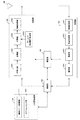
図2は、本実施形態における基地局装置の構成を示す概略ブロック図である。図2に示すように、基地局装置は、上位層処理部(上位層処理ステップ)101、制御部(制御ステップ)102、送信部(送信ステップ)103、受信部(受信ステップ)104と送受信アンテナ105、測定部(測定ステップ)106を含んで構成される。また、上位層処理部101は、無線リソース制御部(無線リソース制御ステップ)1011、スケジューリング部(スケジューリングステップ)1012を含んで構成される。また、送信部103は、符号化部(符号化ステップ)1031、変調部(変調ステップ)1032、下りリンク参照信号生成部(下りリンク参照信号生成ステップ)1033、多重部(多重ステップ)1034、無線送信部(無線送信ステップ)1035を含んで構成される。また、受信部104は、無線受信部(無線受信ステップ)1041、多重分離部(多重分離ステップ)1042、復調部(復調ステップ)1043、復号部(復号ステップ)1044を含んで構成される。
FIG. 2 is a schematic block diagram showing the configuration of the base station apparatus according to the present embodiment. As shown in FIG. 2, the base station apparatus includes an upper layer processing unit (upper layer processing step) 101, a control unit (control step) 102, a transmission unit (transmission step) 103, a reception unit (reception step) 104, and a transmission / reception antenna. It includes 105 and a measuring unit (measurement step) 106. Further, the upper
上位層処理部101は、媒体アクセス制御(Medium Access Control: MAC)層、パケットデータ統合プロトコル(Packet Data Convergence Protocol: PDCP)層、無線リンク制御(Radio Link Control: RLC)層、無線リソース制御(Radio Resource Control: RRC)層の処理を行なう。また、上位層処理部101は、送信部103および受信部104の制御を行なうために必要な情報を生成し、制御部102に出力する。
The upper
上位層処理部101は、端末装置の機能(UE capability)等、端末装置に関する情報
を端末装置から受信する。言い換えると、端末装置は、自身の機能を基地局装置に上位層の信号で送信する。
The upper
なお、以下の説明において、端末装置に関する情報は、その端末装置が所定の機能をサポートするかどうかを示す情報、または、その端末装置が所定の機能に対する導入およびテストの完了を示す情報を含む。なお、以下の説明において、所定の機能をサポートするかどうかは、所定の機能に対する導入およびテストを完了しているかどうかを含む。 In the following description, the information about the terminal device includes information indicating whether or not the terminal device supports a predetermined function, or information indicating that the terminal device has been introduced and tested for the predetermined function. In the following description, whether or not a predetermined function is supported includes whether or not the introduction and testing for the predetermined function have been completed.
例えば、端末装置が所定の機能をサポートする場合、その端末装置はその所定の機能をサポートするかどうかを示す情報(パラメータ)を送信する。端末装置が所定の機能をサポートしない場合、その端末装置はその所定の機能をサポートするかどうかを示す情報(パラメータ)を送信しない。すなわち、その所定の機能をサポートするかどうかは、その所定の機能をサポートするかどうかを示す情報(パラメータ)を送信するかどうかによって通知される。なお、所定の機能をサポートするかどうかを示す情報(パラメータ)は、1または0の1ビットを用いて通知してもよい。 For example, when the terminal device supports a predetermined function, the terminal device transmits information (parameter) indicating whether or not the predetermined function is supported. If the terminal device does not support a predetermined function, the terminal device does not send information (parameter) indicating whether or not the predetermined function is supported. That is, whether or not to support the predetermined function is notified by whether or not to send information (parameter) indicating whether or not to support the predetermined function. Information (parameter) indicating whether or not a predetermined function is supported may be notified using 1 bit of 1 or 0.
無線リソース制御部1011は、下りリンクのPDSCHに配置される下りリンクデータ(トランスポートブロック)、システムインフォメーション、RRCメッセージ、MAC CEなどを生成、又は上位ノードから取得する。無線リソース制御部1011は、下りリンクデータを送信部103に出力し、他の情報を制御部102に出力する。また、無線リソース制御部1011は、端末装置の各種設定情報の管理をする。
The radio
スケジューリング部1012は、物理チャネル(PDSCHおよびPUSCH)を割り
当てる周波数およびサブフレーム、物理チャネル(PDSCHおよびPUSCH)の符号化率および変調方式(あるいはMCS)および送信電力などを決定する。スケジューリング部1012は、決定した情報を制御部102に出力する。
The
スケジューリング部1012は、スケジューリング結果に基づき、物理チャネル(PDSCHおよびPUSCH)のスケジューリングに用いられる情報を生成する。スケジューリング部1012は、生成した情報を制御部102に出力する。
The
制御部102は、上位層処理部101から入力された情報に基づいて、送信部103および受信部104の制御を行なう制御信号を生成する。制御部102は、上位層処理部101から入力された情報に基づいて、下りリンク制御情報を生成し、送信部103に出力する。
The
送信部103は、制御部102から入力された制御信号に従って、下りリンク参照信号を生成し、上位層処理部101から入力されたHARQインディケータ、下りリンク制御情報、および、下りリンクデータを、符号化および変調し、PHICH、PDCCH、EPDCCH、PDSCH、および下りリンク参照信号を多重して、送受信アンテナ105を介して端末装置2Aに信号を送信する。
The
符号化部1031は、上位層処理部101から入力されたHARQインディケータ、下りリンク制御情報、および下りリンクデータを、ブロック符号化、畳み込み符号化、ターボ符号化、LDPC(低密度パリティチェック:Low density parity check)符号化、Polar符号化等の予め定められた符号化方式を用いて符号化を行なう、または無線リソース
制御部1011が決定した符号化方式を用いて符号化を行なう。変調部1032は、符号化部1031から入力された符号化ビットをBPSK(Binary Phase Shift Keying)、
QPSK(quadrature Phase Shift Keying)、16QAM(quadrature amplitude modulation)、64QAM、256QAM等の予め定められた、または無線リソース制御部1011が決定した変調方式で変調する。
The
Modulation is performed by a predetermined modulation method such as QPSK (quadrature Phase Shift Keying), 16QAM (quadrature amplitude modulation), 64QAM, 256QAM, or a modulation method determined by the radio
下りリンク参照信号生成部1033は、基地局装置1Aを識別するための物理セル識別子(PCI、セルID)などを基に予め定められた規則で求まる、端末装置2Aが既知の系列を下りリンク参照信号として生成する。
The downlink reference
多重部1034は、変調された各チャネルの変調シンボルと生成された下りリンク参照信号と下りリンク制御情報とを多重する。つまり、多重部1034は、変調された各チャネルの変調シンボルと生成された下りリンク参照信号と下りリンク制御情報とをリソースエレメントに配置する。
The
無線送信部1035は、多重された変調シンボルなどを逆高速フーリエ変換(Inverse Fast Fourier Transform: IFFT)してOFDMシンボルを生成し、OFDMシンボルにサイクリックプレフィックス(cyclic prefix: CP)を付加してベースバンドのディジタル
信号を生成し、ベースバンドのディジタル信号をアナログ信号に変換し、フィルタリングにより余分な周波数成分を除去し、搬送周波数にアップコンバートし、電力増幅し、送受信アンテナ105に出力して送信する。この時の送信電力は制御部102経由で設定された情報に基づく。
The
受信部104は、制御部102から入力された制御信号に従って、送受信アンテナ105を介して端末装置2Aから受信した受信信号を分離、復調、復号し、復号した情報を上位層処理部101に出力する。なお、受信部104はキャリアセンスを実施する機能(ステップ)も備える。
The receiving
無線受信部1041は、送受信アンテナ105を介して受信された上りリンクの信号を、ダウンコンバートによりベースバンド信号に変換し、不要な周波数成分を除去し、信号レベルが適切に維持されるように増幅レベルを制御し、受信された信号の同相成分および直交成分に基づいて、直交復調し、直交復調されたアナログ信号をディジタル信号に変換する。
The
無線受信部1041は、変換したディジタル信号からCPに相当する部分を除去する。無線受信部1041は、CPを除去した信号に対して高速フーリエ変換(Fast Fourier Transform: FFT)を行い、周波数領域の信号を抽出し多重分離部1042に出力する。
The
多重分離部1042は、無線受信部1041から入力された信号をPUCCH、PUSCH、上りリンク参照信号などの信号に分離する。なお、この分離は、予め基地局装置1Aが無線リソース制御部1011で決定し、各端末装置2Aに通知した上りリンクグラントに含まれる無線リソースの割り当て情報に基づいて行なわれる。
The
また、多重分離部1042は、PUCCHとPUSCHの伝搬路の補償を行なう。また、多重分離部1042は、上りリンク参照信号を分離する。
Further, the
復調部1043は、PUSCHを逆離散フーリエ変換(Inverse Discrete Fourier Transform: IDFT)し、変調シンボルを取得し、PUCCHとPUSCHの変調シンボルそれぞれに対して、BPSK、QPSK、16QAM、64QAM、256QAM等の予め定められた、または自装置が端末装置2Aに上りリンクグラントで予め通知した変調方式を用いて受信信号の復調を行なう。
The
復号部1044は、復調されたPUCCHとPUSCHの符号化ビットを、予め定められた符号化方式の、予め定められた、又は自装置が端末装置2Aに上りリンクグラントで予め通知した符号化率で復号を行ない、復号した上りリンクデータと、上りリンク制御情報を上位層処理部101へ出力する。PUSCHが再送信の場合は、復号部1044は、上位層処理部101から入力されるHARQバッファに保持している符号化ビットと、復調された符号化ビットを用いて復号を行なう。
The
測定部106は、受信信号を観測し、RSRP/RSRQ/RSSIなどの様々な測定値を求める。また測定部106は、端末装置から送信されたSRSから受信電力、受信品質、好適なSRSリソースインデックスを求める。
The measuring
図3は、本実施形態における端末装置の構成を示す概略ブロック図である。図3に示すように、端末装置は、上位層処理部(上位層処理ステップ)201、制御部(制御ステップ)202、送信部(送信ステップ)203、受信部(受信ステップ)204、測定部(測定ステップ)205と送受信アンテナ206を含んで構成される。また、上位層処理部201は、無線リソース制御部(無線リソース制御ステップ)2011、スケジューリング情報解釈部(スケジューリング情報解釈ステップ)2012を含んで構成される。また、送信部203は、符号化部(符号化ステップ)2031、変調部(変調ステップ)2032、上りリンク参照信号生成部(上りリンク参照信号生成ステップ)2033、多重部(多重ステップ)2034、無線送信部(無線送信ステップ)2035を含んで構成される。また、受信部204は、無線受信部(無線受信ステップ)2041、多重分離部(多重分離ステップ)2042、信号検出部(信号検出ステップ)2043を含んで構成される。
FIG. 3 is a schematic block diagram showing the configuration of the terminal device according to the present embodiment. As shown in FIG. 3, the terminal device includes an upper layer processing unit (upper layer processing step) 201, a control unit (control step) 202, a transmission unit (transmission step) 203, a reception unit (reception step) 204, and a measurement unit ( Measurement step) 205 and transmission /
上位層処理部201は、ユーザの操作等によって生成された上りリンクデータ(トラン
スポートブロック)を、送信部203に出力する。また、上位層処理部201は、媒体アクセス制御(Medium Access Control: MAC)層、パケットデータ統合プロトコル(Packet
Data Convergence Protocol: PDCP)層、無線リンク制御(Radio Link Control: RLC)
層、無線リソース制御(Radio Resource Control: RRC)層の処理を行なう。
The upper layer processing unit 201 outputs the uplink data (transport block) generated by the user's operation or the like to the
Data Convergence Protocol (PDCP) layer, Radio Link Control (RLC)
Layers and radio resource control (RRC) layer processing is performed.
上位層処理部201は、自端末装置がサポートしている端末装置の機能を示す情報を、送信部203に出力する。
The upper layer processing unit 201 outputs information indicating the function of the terminal device supported by the own terminal device to the
無線リソース制御部2011は、自端末装置の各種設定情報の管理をする。また、無線リソース制御部2011は、上りリンクの各チャネルに配置される情報を生成し、送信部203に出力する。
The wireless
無線リソース制御部2011は、基地局装置から送信された設定情報を取得し、制御部202に出力する。
The radio
スケジューリング情報解釈部2012は、受信部204を介して受信した下りリンク制御情報を解釈し、スケジューリング情報を判定する。また、スケジューリング情報解釈部2012は、スケジューリング情報に基づき、受信部204、および送信部203の制御を行なうために制御情報を生成し、制御部202に出力する。
The scheduling
制御部202は、上位層処理部201から入力された情報に基づいて、受信部204、測定部205および送信部203の制御を行なう制御信号を生成する。制御部202は、生成した制御信号を受信部204、測定部205および送信部203に出力して受信部204、および送信部203の制御を行なう。
The
制御部202は、測定部205が生成したCSI/RSRP/RSRQ/RSSIを基地局装置に送信するように送信部203を制御する。
The
受信部204は、制御部202から入力された制御信号に従って、送受信アンテナ206を介して基地局装置から受信した受信信号を、分離、復調、復号し、復号した情報を上位層処理部201に出力する。なお、受信部204はキャリアセンスを実施する機能(ステップ)も備える。
The receiving
無線受信部2041は、送受信アンテナ206を介して受信した下りリンクの信号を、ダウンコンバートによりベースバンド信号に変換し、不要な周波数成分を除去し、信号レベルが適切に維持されるように増幅レベルを制御し、受信した信号の同相成分および直交成分に基づいて、直交復調し、直交復調されたアナログ信号をディジタル信号に変換する。
The
また、無線受信部2041は、変換したディジタル信号からCPに相当する部分を除去し、CPを除去した信号に対して高速フーリエ変換を行い、周波数領域の信号を抽出する。
Further, the
多重分離部2042は、抽出した信号をPHICH、PDCCH、EPDCCH、PDSCH、および下りリンク参照信号に、それぞれ分離する。また、多重分離部2042は、チャネル測定から得られた所望信号のチャネルの推定値に基づいて、PHICH、PDCCH、およびEPDCCHのチャネルの補償を行ない、下りリンク制御情報を検出し、制御部202に出力する。また、制御部202は、PDSCHおよび所望信号のチャネル推定値を信号検出部2043に出力する。
The
信号検出部2043は、PDSCH、チャネル推定値を用いて、信号検出し、上位層処理部201に出力する。
The
測定部205は、CSI測定、RRM(Radio Resource Management)測定、RLM(Radio Link Monitoring)測定などの各種測定を行い、CSI/RSRP/RSRQ/RSSIなどを求める。
The measuring
送信部203は、制御部202から入力された制御信号に従って、上りリンク参照信号を生成し、上位層処理部201から入力された上りリンクデータ(トランスポートブロック)を符号化および変調し、PUCCH、PUSCH、および生成した上りリンク参照信号を多重し、送受信アンテナ206を介して基地局装置に送信する。
The
符号化部2031は、上位層処理部201から入力された上りリンク制御情報又は上りリンクデータを畳み込み符号化、ブロック符号化、ターボ符号化、LDPC符号化、Polar符号化等の符号化を行う。
The
変調部2032は、符号化部2031から入力された符号化ビットをBPSK、QPSK、16QAM、64QAM等の下りリンク制御情報で通知された変調方式または、チャネル毎に予め定められた変調方式で変調する。
The
上りリンク参照信号生成部2033は、基地局装置を識別するための物理セル識別子(physical cell identity: PCI、Cell IDなどと称される)、上りリンク参照信号を配置する帯域幅、上りリンクグラントで通知されたサイクリックシフト、DMRSシーケンスの生成に対するパラメータの値などを基に、予め定められた規則(式)で求まる系列を生成する。
The uplink reference
多重部2034は、PUCCHとPUSCHの信号と生成した上りリンク参照信号を送信アンテナポート毎に多重する。つまり、多重部2034は、PUCCHとPUSCHの信号と生成した上りリンク参照信号を送信アンテナポート毎にリソースエレメントに配置する。
The
無線送信部2035は、多重された信号を逆高速フーリエ変換(Inverse Fast Fourier
Transform: IFFT)して、OFDM方式の変調を行い、OFDMAシンボルを生成し、生成されたOFDMAシンボルにCPを付加し、ベースバンドのディジタル信号を生成し、ベースバンドのディジタル信号をアナログ信号に変換し、余分な周波数成分を除去し、アップコンバートにより搬送周波数に変換し、電力増幅し、送受信アンテナ206に出力して送信する。
The
Transform: IFFT) to perform OFDM modulation, generate an OFDMA symbol, add CP to the generated OFDMA symbol, generate a baseband digital signal, and convert the baseband digital signal to an analog signal. Then, the excess frequency component is removed, the frequency is converted to the carrier frequency by up-conversion, the power is amplified, and the signal is output to the transmission /
なお、端末装置はOFDMA方式に限らず、SC−FDMA方式の変調を行うことができる。 The terminal device is not limited to the OFDMA system, and can perform modulation of the SC-FDMA system.
超高精細映像伝送など、超大容量通信が要求される場合、高周波数帯を活用した超広帯域伝送が望まれる。高周波数帯における伝送は、パスロスを補償することが必要であり、ビームフォーミングが重要となる。また、ある限定されたエリアに複数の端末装置が存在する環境において、各端末装置に対して超大容量通信が要求される場合、基地局装置を高密度に配置した超高密度ネットワーク(Ultra-dense network)が有効である。しかしな
がら、基地局装置を高密度に配置した場合、SNR(信号対雑音電力比:Signal to noise
power ratio)は大きく改善するものの、ビームフォーミングによる強い干渉が到来する
可能性がある。従って、限定エリア内のあらゆる端末装置に対して、超大容量通信を実現するためには、ビームフォーミングを考慮した干渉制御(回避、抑圧、除去)、及び/又
は、複数の基地局の協調通信が必要となる。
When ultra-large capacity communication is required, such as ultra-high-definition video transmission, ultra-wideband transmission utilizing the high frequency band is desired. Transmission in the high frequency band needs to compensate for path loss, and beamforming is important. Further, in an environment where a plurality of terminal devices exist in a limited area, when ultra-large capacity communication is required for each terminal device, an ultra-dense network in which base station devices are arranged at high density (Ultra-dense). network) is valid. However, when the base station equipment is arranged at high density, SNR (Signal to Noise)
Although the power ratio) is greatly improved, strong interference due to beamforming may arrive. Therefore, in order to realize ultra-large capacity communication for all terminal devices in a limited area, interference control (avoidance, suppression, elimination) considering beamforming and / or coordinated communication of a plurality of base stations is performed. You will need it.
図4は、本実施形態に係る下りリンクの通信システムの例を示す。図4に示す通信システムは基地局装置3A、基地局装置5A、端末装置4Aを備える。端末装置4Aは、基地局装置3A及び/又は基地局装置5Aをサービングセルとすることができる。また基地局装置3A又は基地局装置5Aが多数のアンテナを備えている場合、多数のアンテナを複数のサブアレー(パネル、サブパネル)に分けることができ、サブアレー毎に送信/受信ビームフォーミングを適用できる。この場合、各サブアレーは通信装置を備えることができ、通信装置の構成は特に断りがない限り、図2で示した基地局装置構成と同様である。また端末装置4Aが複数のアンテナを備えている場合、端末装置4Aはビームフォーミングにより送信又は受信することができる。また、端末装置4Aが多数のアンテナを備えている場合、多数のアンテナを複数のサブアレー(パネル、サブパネル)に分けることができ、サブアレー毎に異なる送信/受信ビームフォーミングを適用できる。各サブアレーは通信装置を備えることができ、通信装置の構成は特に断りがない限り、図3で示した端末装置構成と同様である。なお、基地局装置3A、基地局装置5Aを単に基地局装置とも呼ぶ。なお、端末装置4Aを単に端末装置とも呼ぶ。
FIG. 4 shows an example of a downlink communication system according to the present embodiment. The communication system shown in FIG. 4 includes a
基地局装置の好適な送信ビーム、端末装置の好適な受信ビームを決定するために、同期信号が用いられる。基地局装置は、PSS、PBCH、SSSで構成される同期信号ブロック(SS block、SSB)を送信する。なお、基地局装置が設定する同期信号ブロックバーストセット周期内で、同期信号ブロックは、時間領域に1又は複数個送信され、各々の同期信号ブロックには、時間インデックスが設定される。端末装置は、同期信号ブロックバーストセット周期内で同じ時間インデックスの同期信号ブロックは、遅延スプレッド、ドップラースプレッド、ドップラーシフト、平均利得、平均遅延、空間的な受信パラメータ、及び/又は空間的な送信パラメータが同じとみなせるような、ある程度同じ位置(quasi co-located: QCL)から送信されたと見なしてよい。なお、空間的な受信パ
ラメータは、例えば、チャネルの空間相関、到来角(Angle of Arrival)などである。また空間的な送信パラメータは、例えば、チャネルの空間相関、送信角(Angle of Departure)などである。つまり端末装置は、同期信号ブロックバーストセット周期内で同じ時間インデックスの同期信号ブロックは同じ送信ビームで送信され、異なる時間インデックスの同期信号ブロックは異なるビームで送信されたと想定することができる。従って、端末装置が同期信号ブロックバーストセット周期内の好適な同期信号ブロックの時間インデックスを示す情報を基地局装置に報告すれば、基地局装置は端末装置に好適な送信ビームを知ることができる。また、端末装置は、異なる同期信号ブロックバーストセット周期で同じ時間インデックスの同期信号ブロックを用いて端末装置に好適な受信ビームを求めることができる。このため、端末装置は、同期信号ブロックの時間インデックスと受信ビーム方向及び/又はサブアレーを関連付けることができる。なお、端末装置は、複数のサブアレーを備えている場合、異なるセルと接続するときは、異なるサブアレーを用いるとしてもよい。
Synchronous signals are used to determine a suitable transmit beam for a base station device and a suitable receive beam for a terminal device. The base station apparatus transmits a synchronization signal block (SS block, SSB) composed of PSS, PBCH, and SSS. Within the synchronization signal block burst set cycle set by the base station apparatus, one or more synchronization signal blocks are transmitted in the time domain, and a time index is set for each synchronization signal block. The terminal device has the same time index sync signal block within the sync signal block burst set cycle, delay spread, Doppler spread, Doppler shift, average gain, average delay, spatial receive parameters, and / or spatial transmit parameters. Can be considered to have been sent from the same location (quasi co-located: QCL) to some extent so that they can be considered the same. The spatial reception parameters are, for example, the spatial correlation of the channel, the angle of arrival, and the like. The spatial transmission parameters are, for example, the spatial correlation of the channel, the transmission angle (Angle of Departure), and the like. That is, the terminal device can assume that the synchronization signal blocks of the same time index are transmitted by the same transmission beam and the synchronization signal blocks of different time indexes are transmitted by different beams within the synchronization signal block burst set cycle. Therefore, if the terminal device reports to the base station device the information indicating the time index of the suitable sync signal block within the sync signal block burst set cycle, the base station device can know the transmission beam suitable for the terminal device. Further, the terminal device can obtain a reception beam suitable for the terminal device by using the synchronization signal blocks having the same time index in different synchronization signal block burst set cycles. Therefore, the terminal device can associate the time index of the synchronization signal block with the received beam direction and / or the sub-array. When the terminal device includes a plurality of sub-arrays, different sub-arrays may be used when connecting to different cells.
また、好適な基地局装置の送信ビームと好適な端末装置の受信ビームを決定するために、CSI−RSを用いることができる。基地局装置は、上位層の信号で設定情報を設定することができる。例えば、設定情報は、リソース設定、報告設定の一部又は全部を含む。 In addition, CSI-RS can be used to determine the transmit beam of a suitable base station apparatus and the receive beam of a suitable terminal apparatus. The base station device can set the setting information by the signal of the upper layer. For example, the configuration information includes some or all of the resource settings, reporting settings.
リソース設定は、リソース設定ID、リソース設定タイプ、及び/又は、1又は複数のCSI−RSリソースセット設定を含む。リソース設定IDは、リソース設定を特定するために用いられる。リソース設定タイプは、リソース設定の時間領域の動作を示す。具体的には、リソース設定が非周期的(aperiodic)にCSI−RSを送信する設定、周期的
(periodic)にCSI−RSを送信する設定、又は半永続的(semi-persistent)にCS
I−RSを送信する設定であるかを示す。CSI−RSリソースセット設定は、CSI−
RSリソースセット設定ID、及び/又は、1又は複数のCSI−RSリソース設定を含む。CSI−RSリソースセット設定IDは、CSI−RSリソースセット設定を特定するために用いられる。CSI−RSリソース設定は、CSI−RSリソース設定ID、リソース設定タイプ、アンテナポート数、CSI−RSリソースマッピング、CSI−RSとPDSCHの電力オフセットの一部又は全部を含む。CSI−RSリソース設定IDは、CSI−RSリソース設定を特定するために用いられ、CSI−RSリソース設定IDでCSI−RSリソースが関連付けられる。CSI−RSリソースマッピングは、スロット内のCSI−RSが配置されるリソースエレメント(OFDMシンボル、サブキャリア)を示す。
Resource settings include a resource setting ID, a resource setting type, and / or one or more CSI-RS resource set settings. The resource setting ID is used to specify the resource setting. The resource setting type indicates the behavior of the resource setting in the time domain. Specifically, the resource setting is a setting to send CSI-RS aperiodically, a setting to send CSI-RS periodically (periodic), or a semi-persistent CS.
Indicates whether it is set to transmit I-RS. CSI-RS resource set settings are CSI-
Includes RS resource set configuration ID and / or one or more CSI-RS resource configurations. The CSI-RS resource set setting ID is used to identify the CSI-RS resource set setting. The CSI-RS resource configuration includes a CSI-RS resource configuration ID, a resource configuration type, the number of antenna ports, a CSI-RS resource mapping, and some or all of the CSI-RS and PDSCH power offsets. The CSI-RS resource setting ID is used to identify the CSI-RS resource setting, and the CSI-RS resource setting ID is associated with the CSI-RS resource. The CSI-RS resource mapping indicates a resource element (OFDM symbol, subcarrier) in which the CSI-RS in the slot is placed.
リソース設定は、CSI測定又はRRM測定に用いられる。端末装置は、設定されたリソースでCSI−RSを受信し、CSI−RSからCSIを算出し、基地局装置に報告する。また、CSI−RSリソースセット設定が複数のCSI−RSリソース設定を含む場合、端末装置は、各々のCSI−RSリソースで同じ受信ビームでCSI−RSを受信し、CRIを計算する。例えば、CSI−RSリソースセット設定がK(Kは2以上の整数)個のCSI−RSリソース設定を含む場合、CRIはK個のCSI−RSリソースから好適なN個のCSI−RSリソースを示す。ただし、NはK未満の正の整数である。またCRIが複数のCSI−RSリソースを示す場合、どのCSI−RSリソースの品質が良いかを示すために、端末装置は各CSI−RSリソースで測定したCSI−RSRPを基地局装置に報告することができる。基地局装置は、複数設定したCSI−RSリソースで各々異なるビーム方向でCSI−RSをビームフォーミング(プリコーディング)して送信すれば、端末装置から報告されたCRIにより端末装置に好適な基地局装置の送信ビーム方向を知ることができる。一方、好適な端末装置の受信ビーム方向は、基地局装置の送信ビームが固定されたCSI−RSリソースを用いて決定できる。例えば、基地局装置は、あるCSI−RSリソースに対して、基地局装置の送信ビームが固定されているか否かを示す情報、及び/又は、送信ビームが固定されている期間を送信する。端末装置は、送信ビームが固定されているCSI−RSリソースにおいて、各々異なる受信ビーム方向で受信したCSI−RSから好適な受信ビーム方向を求めることができる。なお、端末装置は、好適な受信ビーム方向を決定した後、CSI−RSRPを報告してもよい。なお、端末装置が複数のサブアレーを備えている場合、端末装置は、好適な受信ビーム方向を求める際に、好適なサブアレーを選択することができる。なお、端末装置の好適な受信ビーム方向は、CRIと関連付けられても良い。また端末装置が複数のCRIを報告した場合、基地局装置は、各CRIと関連付けられたCSI−RSリソースで送信ビームを固定することができる。このとき、端末装置は、CRI毎に、好適な受信ビーム方向を決定することができる。例えば、基地局装置は下りリンク信号/チャネルとCRIを関連付けて送信することができる。このとき、端末装置は、CRIと関連付けられた受信ビームで受信しなければならない。また、設定された複数のCSI−RSリソースにおいて、異なる基地局装置がCSI−RSを送信することができる。この場合、CRIによりどの基地局装置からの通信品質が良いかをネットワーク側が知ることができる。また、端末装置が複数のサブアレーを備えている場合、同じタイミングで複数のサブアレーで受信することができる。従って、基地局装置が下りリンク制御情報などで複数レイヤ(コードワード、トランスポートブロック)の各々にCRIを関連付けて送信すれば、端末装置は、各CRIに対応するサブアレー、受信ビームを用いて、複数レイヤを受信することができる。ただし、アナログビームを用いる場合、1つのサブアレーで同じタイミングで用いられる受信ビーム方向が1つであるとき、端末装置の1つのサブアレーに対応する2つのCRIが同時に設定された場合に、端末装置は複数の受信ビームで受信することができない可能性がある。この問題を回避するために、例えば、基地局装置は設定した複数のCSI−RSリソースをグループ分けし、グループ内は、同じサブアレーを用いてCRIを求める。またグループ間で異なるサブアレーを用いれば、基地局装置は同じタイミングで設定することができる複数のCRIを知ることができる。なお、CSI−RSリソースのグループは、CS
I−RSリソースセットでもよい。なお、同じタイミングで設定できるCRIをQCLであるとしてもよい。このとき、端末装置は、QCL情報と関連付けてCRIを送信することができる。例えば、端末装置は、QCLであるCRIとQCLではないCRIを区別して報告すれば、基地局装置はQCLであるCRIは同じタイミングに設定せず、QCLではないCRIは同じタイミングに設定する、ことができる。また、基地局装置は、端末装置のサブアレー毎にCSIを要求してもよい。この場合、端末装置は、サブアレー毎にCSIを報告する。なお、端末装置は複数のCRIを基地局装置に報告する場合、QCLでないCRIのみを報告しても良い。
Resource settings are used for CSI or RRM measurements. The terminal device receives the CSI-RS with the set resource, calculates the CSI from the CSI-RS, and reports it to the base station device. Further, when the CSI-RS resource set setting includes a plurality of CSI-RS resource settings, the terminal device receives the CSI-RS with the same reception beam for each CSI-RS resource and calculates the CRI. For example, if the CSI-RS resource set setting includes K (K is an integer greater than or equal to 2) CSI-RS resource settings, the CRI indicates from K CSI-RS resources to suitable N CSI-RS resources. .. However, N is a positive integer less than K. If the CRI indicates multiple CSI-RS resources, the terminal device should report the CSI-RSRP measured by each CSI-RS resource to the base station device in order to indicate which CSI-RS resource is of good quality. Can be done. If the base station apparatus beamforms (precodes) CSI-RS in different beam directions with a plurality of set CSI-RS resources and transmits the CSI-RS, the base station apparatus suitable for the terminal apparatus by the CRI reported from the terminal apparatus. You can know the transmission beam direction of. On the other hand, the reception beam direction of a suitable terminal device can be determined by using a CSI-RS resource in which the transmission beam of the base station device is fixed. For example, the base station apparatus transmits information indicating whether or not the transmission beam of the base station apparatus is fixed, and / or a period during which the transmission beam is fixed, to a certain CSI-RS resource. The terminal device can obtain a suitable reception beam direction from the CSI-RS received in different reception beam directions in the CSI-RS resource in which the transmission beam is fixed. The terminal device may report CSI-RSRP after determining a suitable receiving beam direction. When the terminal device includes a plurality of sub-arrays, the terminal device can select a suitable sub-array when determining a suitable reception beam direction. It should be noted that the preferred receiving beam direction of the terminal device may be associated with the CRI. Also, if the terminal device reports multiple CRIs, the base station device can fix the transmit beam with the CSI-RS resource associated with each CRI. At this time, the terminal device can determine a suitable reception beam direction for each CRI. For example, the base station device can transmit the downlink signal / channel in association with the CRI. At this time, the terminal device must receive with the reception beam associated with the CRI. Further, different base station devices can transmit CSI-RS in a plurality of set CSI-RS resources. In this case, the network side can know from which base station device the communication quality is good by CRI. Further, when the terminal device has a plurality of sub-arrays, it is possible to receive the signals in the plurality of sub-arrays at the same timing. Therefore, if the base station device transmits the CRI in association with each of the plurality of layers (codeword, transport block) by the downlink control information or the like, the terminal device uses the sub-array and the received beam corresponding to each CRI. Can receive multiple layers. However, when using an analog beam, when one sub-array uses one receiving beam direction at the same timing, and two CRIs corresponding to one sub-array of the terminal device are set at the same time, the terminal device is used. It may not be possible to receive with multiple receive beams. In order to avoid this problem, for example, the base station apparatus groups a plurality of set CSI-RS resources, and within the group, the same sub-array is used to obtain CRI. Further, if different sub-arrays are used between groups, the base station apparatus can know a plurality of CRIs that can be set at the same timing. The CSI-RS resource group is CS.
It may be an I-RS resource set. The CRI that can be set at the same timing may be a QCL. At this time, the terminal device can transmit the CRI in association with the QCL information. For example, if the terminal device reports a CRI that is a QCL and a CRI that is not a QCL separately, the base station device does not set the CRI that is a QCL at the same timing, and the CRI that is not a QCL is set at the same timing. Can be done. Further, the base station apparatus may request CSI for each sub-array of the terminal apparatus. In this case, the terminal device reports the CSI for each sub-array. When the terminal device reports a plurality of CRIs to the base station device, it may report only the CRIs that are not QCLs.
報告設定は、CSI報告に関する設定であり、報告設定ID、報告設定タイプ、及び/又は報告値(量)を含む。報告設定IDは、報告設定を特定するために用いられる。報告値(量)は報告するCSI値(量)である。報告設定タイプは、報告設定が、非周期的(aperiodic)にCSI値(量)を報告する設定、周期的(periodic)にCSI値(量)を
報告する設定、又は半永続的(semi-persistent)にCSI値(量)を報告する設定であ
る。
The reporting settings are settings for CSI reporting and include a reporting setting ID, a reporting setting type, and / or a reporting value (quantity). The report setting ID is used to identify the report setting. The reported value (quantity) is the CSI value (quantity) to be reported. The reporting setting type is a setting in which the reporting setting reports the CSI value (quantity) aperiodically, the CSI value (quantity) in a periodic manner, or semi-persistent. ) Is set to report the CSI value (quantity).
非周期的もしくは半永続的にCSIを報告する場合、基地局装置は端末装置に対して、当該CSIの報告を開始させるトリガ(トリガ情報)を送信する。該トリガは、DCIであることが出来るし、上位レイヤのシグナリングであることができる。 When reporting a CSI aperiodically or semi-permanently, the base station device sends a trigger (trigger information) to start reporting the CSI to the terminal device. The trigger can be DCI or can be higher layer signaling.
また、好適な基地局装置の送信ビームを決定するために、所定のプリコーディング(ビームフォーミング)行列(ベクトル)の候補が規定されたコードブックが用いられる。基地局装置はCSI−RSを送信し、端末装置はコードブックの中から好適なプリコーディング(ビームフォーミング)行列を求め、PMIとして基地局装置に報告する。これにより、基地局装置は、端末装置にとって好適な送信ビーム方向を知ることができる。なお、コードブックにはアンテナポートを合成するプリコーディング(ビームフォーミング)行列と、アンテナポートを選択するプリコーディング(ビームフォーミング)行列がある。アンテナポートを選択するコードブックを用いる場合、基地局装置はアンテナポート毎に異なる送信ビーム方向を用いることができる。従って、端末装置がPMIとして好適なアンテナポートを報告すれば、基地局装置は好適な送信ビーム方向を知ることができる。なお、端末装置の好適な受信ビームは、CRIに関連付けられた受信ビーム方向でもよいし、再度好適な受信ビーム方向を決定しても良い。アンテナポートを選択するコードブックを用いる場合に、端末装置の好適な受信ビーム方向がCRIに関連付けられた受信ビーム方向とする場合、CSI−RSを受信する受信ビーム方向はCRIに関連付けられた受信ビーム方向で受信することが望ましい。なお、端末装置は、CRIに関連付けられた受信ビーム方向を用いる場合でも、PMIと受信ビーム方向を関連付けることができる。また、アンテナポートを選択するコードブックを用いる場合、各々のアンテナポートは異なる基地局装置(セル)から送信されても良い。この場合、端末装置がPMIを報告すれば、基地局装置はどの基地局装置(セル)との通信品質が好適かを知ることができる。なお、この場合、異なる基地局装置(セル)のアンテナポートはQCLではないとすることができる。 Further, in order to determine a suitable transmission beam of the base station apparatus, a codebook in which candidates for a predetermined precoding (beamforming) matrix (vector) are defined is used. The base station apparatus transmits CSI-RS, and the terminal apparatus obtains a suitable precoding (beamforming) matrix from the codebook and reports it to the base station apparatus as PMI. Thereby, the base station apparatus can know the transmission beam direction suitable for the terminal apparatus. The codebook has a precoding (beamforming) matrix for synthesizing antenna ports and a precoding (beamforming) matrix for selecting antenna ports. When using a codebook for selecting antenna ports, the base station device can use different transmission beam directions for each antenna port. Therefore, if the terminal device reports an antenna port suitable for PMI, the base station device can know the suitable transmission beam direction. The suitable reception beam of the terminal device may be the reception beam direction associated with the CRI, or the suitable reception beam direction may be determined again. When using a codebook that selects an antenna port, if the preferred receive beam direction of the terminal device is the receive beam direction associated with the CRI, then the receive beam direction that receives the CSI-RS is the receive beam associated with the CRI. It is desirable to receive in the direction. It should be noted that the terminal device can associate the PMI with the received beam direction even when the received beam direction associated with the CRI is used. Further, when a codebook for selecting an antenna port is used, each antenna port may be transmitted from a different base station device (cell). In this case, if the terminal device reports the PMI, the base station device can know which base station device (cell) the communication quality is suitable for. In this case, it can be said that the antenna ports of different base station devices (cells) are not QCLs.
PUSCHでCSIが報告される場合、又はPUCCHでサブバンドCSIが報告される場合、CSIは2つのパートに分割されて報告される。また、CSI報告は、タイプ1CSI報告とタイプ2CSI報告がある。タイプ1CSI報告では、タイプ1コードブックに基づくCSI(タイプ1CSIとも呼ぶ)が報告される。タイプ2CSI報告では、タイプ2コードブックに基づくCSI(タイプ2CSIとも呼ぶ)が報告される。また、2つのパートを第1のパート(パート1、CSIパート1)、第2のパート(パート2、CSIパート2)とも呼ぶ。なお、第1のパートは第2のパートよりもCSI報告の優先度は高い。例えば、RIが4以下の場合、第1のパートは第1のRIと第2のRIの合計
(又は第2のRI)、第2のCRI、第1のCRI及び第2のCRIに基づくCQI(又は第2のCQI)の一部又は全部を含む。第2のパートは第1のCRI、第1のRI、第1のCQI、第1のPMI、第2のPMIの一部又は全部を含む。RIが4よりも大きい場合、第1のパートは、第1のRIと第2のRIの合計(又は第2のRI)、第2のCRI、第2のCQIの一部又は全部を含む。第2のパートは、第1のCRI、第1のRI、第1のCQI、第1のPMI、第2のPMIの一部又は全部を含む。なお、CSIを3つに分割しても良い。3つ目のパートを第3のパート(パート3、CSIパート3)とも呼ぶ。第3のパートは第2のパートよりも優先度は低い。このとき、第1のパートは第1のRIと第2のRIの合計(又は第2のRI)、第2のCRI、第1のCRI及び第2のCRIに基づくCQI(又は第2のCQI)の一部又は全部を含む。第2のパートは第1のCRI、第1のRI、第1のCQIの一部又は全部を含む。第3のパートは、第1のPMI、第2のPMIの一部又は全部を含む。
If the CSI is reported on the PUSCH, or if the subband CSI is reported on the PUCCH, the CSI is reported in two parts. In addition, CSI reports include type 1 CSI reports and type 2 CSI reports. In the Type 1 CSI report, the CSI based on the Type 1 codebook (also referred to as the Type 1 CSI) is reported. In the Type 2 CSI report, the CSI based on the Type 2 codebook (also referred to as the Type 2 CSI) is reported. The two parts are also referred to as a first part (part 1, CSI part 1) and a second part (part 2, CSI part 2). The first part has a higher priority for CSI reporting than the second part. For example, if the RI is 4 or less, the first part is the sum of the first RI and the second RI (or the second RI), the second CRI, the first CRI and the CQI based on the second CRI. Includes part or all of (or the second CQI). The second part includes a first CRI, a first RI, a first CQI, a first PMI, a part or all of a second PMI. If the RI is greater than 4, the first part includes the sum of the first RI and the second RI (or the second RI), the second CRI, and some or all of the second CQI. The second part includes a first CRI, a first RI, a first CQI, a first PMI, a part or all of the second PMI. The CSI may be divided into three. The third part is also called the third part (part 3, CSI part 3). The third part has a lower priority than the second part. At this time, the first part is the sum of the first RI and the second RI (or the second RI), the second CRI, the first CRI and the CQI based on the second CRI (or the second CQI). ) Including part or all. The second part includes a part or all of the first CRI, the first RI, and the first CQI. The third part includes a first PMI, a part or all of the second PMI.
なお、端末装置は、第1のCRIに基づくCSIと第2のCRIに基づくCSIの各々で2つのパートに分割して報告しても良い。なお、第1のCRIに基づくCSIの2つのパートを第1のパート1、第1のパート2とも呼ぶ。また、第2のCRIに基づくCSIの2つのパートを第2のパート1、第2のパート2とも呼ぶ。なお、第1のパート1は、第1のCRI、第1のRI、第1のCQIの一部又は全部を含む。また、第1のパート2は、第1のPMIを含む。また、第2のパート1は、第2のCRI、第2のRI、第2のCQIの一部又は全部を含む。また、第2のパート2は、第2のPMIを含む。なお、CSIの優先度は、第2のパート1、第1のパート1、第2のパート2、第1のパート2の順に高く設定することができる。このとき、端末装置は第2のCRI及び第1のCRIで長周期(変化の少ない)なCSIを報告することになり、基地局装置及び端末装置は第1のCRI及び第2のCRIに関する最低限のパラメータを用いて通信することができる。また、CSIの優先度は、第2のパート1、第2のパート2、第1のパート1、第1のパート2の順に高く設定することができる。このとき、端末装置は第2のCRIにおける完全なCSIを優先的に報告することで、基地局装置及び端末装置は第2のCRIに関する詳細なパラメータを用いて通信することができる。 The terminal device may be divided into two parts for each of the CSI based on the first CRI and the CSI based on the second CRI and reported. The two parts of CSI based on the first CRI are also referred to as the first part 1 and the first part 2. Further, the two parts of CSI based on the second CRI are also referred to as the second part 1 and the second part 2. The first part 1 includes a part or all of the first CRI, the first RI, and the first CQI. Also, the first part 2 includes the first PMI. Also, the second part 1 includes a part or all of the second CRI, the second RI, and the second CQI. The second part 2 also includes a second PMI. The priority of CSI can be set higher in the order of the second part 1, the first part 1, the second part 2, and the first part 2. At this time, the terminal device will report a long-period (small change) CSI in the second CRI and the first CRI, and the base station device and the terminal device will report the minimum regarding the first CRI and the second CRI. It is possible to communicate using the parameters of the limit. Further, the priority of CSI can be set higher in the order of the second part 1, the second part 2, the first part 1, and the first part 2. At this time, the terminal device preferentially reports the complete CSI in the second CRI, so that the base station device and the terminal device can communicate using detailed parameters related to the second CRI.
端末装置4Aは、サービングセルに加え、隣接セルからの干渉信号(隣接セル干渉)を受信する可能性がある。干渉信号は、隣接セルのPDSCH、PDCCH、又は参照信号である。この場合、端末装置における干渉信号の除去又は抑圧が有効である。干渉信号を除去又は抑圧する方式として、干渉信号のチャネルを推定して線形ウェイトにより抑圧するE−MMSE(Enhanced - Minimum Mean Square Error)、干渉信号のレプリカを生成して除去する干渉キャンセラ、所望信号と干渉信号の送信信号候補を全探索して所望信号を検出するMLD(Maximum Likelihood Detection)、送信信号候補を削減してMLDよりも低演算量にしたR−MLD(Reduced complexity - MLD)などが適用できる。これらの方式を適用するためには、干渉信号のチャネル推定、干渉信号の復調、又は干渉信号の復号が必要となる。そのため、効率的に干渉信号を除去又は抑圧するために、端末装置は干渉信号(隣接セル)のパラメータを知る必要がある。そこで、基地局装置は、端末装置による干渉信号の除去又は抑圧を支援するために、干渉信号(隣接セル)のパラメータを含むアシスト情報を端末装置に送信(設定)することができる。アシスト情報は1又は複数設定される。アシスト情報は、例えば、物理セルID、仮想セルID、参照信号とPDSCHの電力比(電力オフセット)、参照信号のスクランブリングアイデンティティ、QCL情報(quasi co-location information)、CSI−RSリソース設定、CSI−R
Sアンテナポート数、サブキャリア間隔、リソース割当て粒度、リソース割当て情報、DMRS設定、DMRSアンテナポート番号、レイヤ数、TDD DL/UL構成、PMI、RI、変調方式、MCS(Modulation and coding scheme)の一部又は全部を含む。なお、仮想セルIDはセルに仮想的に割当てられたIDであり、物理セルIDは同じで仮想セルIDは異なるセルがあり得る。QCL情報は、所定のアンテナポート、所定の信号、
又は所定のチャネルに対するQCLに関する情報である。2つのアンテナポートにおいて、一方のアンテナポート上のシンボルが搬送されるチャネルの長区間特性が、もう一方のアンテナポート上のシンボルが搬送されるチャネルから推測できる場合、それらのアンテナポートはQCLであると呼称される。長区間特性は、遅延スプレッド、ドップラースプレッド、ドップラーシフト、平均利得、平均遅延、空間的な受信パラメータ、及び/又は空間的な送信パラメータを含む。すなわち、2つのアンテナポートがQCLである場合、端末装置はそれらのアンテナポートにおける長区間特性が同じであると見なすことができる。サブキャリア間隔は、干渉信号のサブキャリア間隔、又はそのバンドで使用する可能性のあるサブキャリア間隔の候補を示す。なお、アシスト情報に含まれるサブキャリア間隔とサービングセルとの通信で用いるサブキャリア間隔が異なる場合は、端末装置は干渉信号を除去又は抑圧しなくてもよい。そのバンドで使用する可能性のあるサブキャリア間隔の候補は、通常用いられるサブキャリア間隔を示しても良い。例えば、通常用いられるサブキャリア間隔には、高信頼・低遅延通信(緊急通信)に用いられるような低頻度のサブキャリア間隔は含まなくても良い。リソース割当て粒度は、プリコーディング(ビームフォーミング)が変わらないリソースブロック数を示す。DMRS設定は、PDSCHマッピングタイプ、DMRSの追加配置を示す。PDSCHマッピングタイプによってDMRSリソース割当ては変わる。例えば、PDSCHマッピングタイプAは、スロットの第3シンボルにDMRSはマッピングされる。また、例えば、PDSCHマッピングタイプBは割当てられたPDSCHリソースの最初のOFDMシンボルにマッピングされる。DMRSの追加配置は、追加のDMRS配置があるか否か、又は追加される配置を示す。なお、アシスト情報に含まれる一部又は全部のパラメータは上位層の信号で送信(設定)される。また、アシスト情報に含まれる一部又は全部のパラメータは下りリンク制御情報で送信される。また、アシスト情報に含まれる各々のパラメータが複数の候補を示す場合、端末装置は候補の中から好適なものをブラインド検出する。また、アシスト情報に含まれないパラメータは、端末装置がブラインド検出する。
The
One of S antenna port number, subcarrier interval, resource allocation particle size, resource allocation information, DMRS setting, DMRS antenna port number, number of layers, TDD DL / UL configuration, PMI, RI, modulation method, MCS (Modulation and coding scheme) Including part or all. The virtual cell ID is an ID virtually assigned to the cell, and there may be cells having the same physical cell ID but different virtual cell IDs. QCL information is a predetermined antenna port, a predetermined signal,
Or information about the QCL for a given channel. In two antenna ports, if the long section characteristics of the channel carrying the symbol on one antenna port can be inferred from the channel carrying the symbol on the other antenna port, then those antenna ports are QCL. Is called. Long interval characteristics include delay spreads, Doppler spreads, Doppler shifts, average gains, average delays, spatial receive parameters, and / or spatial transmit parameters. That is, if the two antenna ports are QCLs, the terminal device can be considered to have the same long section characteristics at those antenna ports. The subcarrier spacing indicates a candidate for the subcarrier spacing of the interfering signal, or the subcarrier spacing that may be used in that band. If the subcarrier interval included in the assist information and the subcarrier interval used for communication with the serving cell are different, the terminal device may not remove or suppress the interference signal. Candidates for subcarrier spacing that may be used in that band may indicate commonly used subcarrier spacing. For example, the normally used subcarrier interval does not have to include the low frequency subcarrier interval used for high reliability and low delay communication (emergency communication). The resource allocation particle size indicates the number of resource blocks whose precoding (beamforming) does not change. The DMRS setting indicates the PDSCH mapping type, additional placement of DMRS. DMRS resource allocation varies depending on the PDSCH mapping type. For example, in PDSCH mapping type A, DMRS is mapped to the third symbol of the slot. Also, for example, the PDSCH mapping type B is mapped to the first OFDM symbol of the allocated PDSCH resource. The additional arrangement of DMRS indicates whether or not there is an additional DMRS arrangement, or the arrangement to be added. Some or all the parameters included in the assist information are transmitted (set) by the signal of the upper layer. In addition, some or all parameters included in the assist information are transmitted as downlink control information. Further, when each parameter included in the assist information indicates a plurality of candidates, the terminal device blindly detects a suitable candidate from the candidates. Further, the terminal device blindly detects the parameters not included in the assist information.
端末装置は複数の受信ビーム方向を用いて通信する場合、受信ビーム方向によって、周囲の干渉状況は大きく変化する。例えば、ある受信ビーム方向では強かった干渉信号が別の受信ビーム方向では弱くなることがあり得る。強い干渉になる可能性が低いセルのアシスト情報は、意味がないだけではなく、強い干渉信号を受信しているか否かを判断する際に無駄な計算をしてしまう可能性がある。従って、上記アシスト情報は受信ビーム方向ごとに設定されることが望ましい。ただし、基地局装置は端末装置の受信方向を必ずしも知らないため、受信ビーム方向に関連する情報とアシスト情報を関連付ければよい。例えば、端末装置は、CRIと受信ビーム方向を関連付けることができるため、基地局装置はCRI毎に1又は複数のアシスト情報を送信(設定)することができる。また、端末装置は同期信号ブロックの時間インデックスと受信ビーム方向を関連付けることができるため、基地局装置は、同期信号ブロックの時間インデックスごとに1又は複数のアシスト情報を送信(設定)することができる。また、端末装置は、PMI(アンテナポート番号)と受信ビーム方向を関連付けることができるため、基地局装置はPMI(アンテナポート番号)毎に1又は複数のアシスト情報を送信(設定)することができる。また、端末装置が複数のサブアレーを備える場合、サブアレー毎に受信ビーム方向が変わる可能性が高いため、基地局装置は端末装置のサブアレーと関連するインデックス毎に1又は複数のアシスト情報を送信(設定)することができる。また、複数の基地局装置(送受信ポイント)と端末装置が通信する場合、端末装置は各々の基地局装置(送受信ポイント)と異なる受信ビーム方向で通信する可能性が高い。そのため、基地局装置は、基地局装置(送受信ポイント)を示す情報ごとに1又は複数のアシスト情報を送信(設定)する。基地局装置(送受信ポイント)を示す情報は、物理セルID又は仮想セルIDとしてもよい。また、基地局装置(送受信ポイント)で異なるDMRSアンテナポート番号を用いる場合、DMRSアンテナポート番号やDMRSアンテナグループを示す情報が基地局装置(送受信ポイント)を示す情報となる。 When the terminal device communicates using a plurality of reception beam directions, the surrounding interference situation changes greatly depending on the reception beam direction. For example, an interference signal that was strong in one receive beam direction may weaken in another receive beam direction. The assist information of the cell, which is unlikely to cause strong interference, is not only meaningless, but also may cause unnecessary calculation when determining whether or not a strong interference signal is received. Therefore, it is desirable that the assist information is set for each received beam direction. However, since the base station device does not necessarily know the reception direction of the terminal device, it is sufficient to associate the information related to the reception beam direction with the assist information. For example, since the terminal device can associate the CRI with the received beam direction, the base station device can transmit (set) one or more assist information for each CRI. Further, since the terminal device can associate the time index of the synchronization signal block with the reception beam direction, the base station device can transmit (set) one or more assist information for each time index of the synchronization signal block. .. Further, since the terminal device can associate the PMI (antenna port number) with the reception beam direction, the base station device can transmit (set) one or more assist information for each PMI (antenna port number). .. Further, when the terminal device has a plurality of sub-arrays, the receiving beam direction is likely to change for each sub-array, so that the base station device transmits (sets) one or more assist information for each index related to the sub-array of the terminal device. )can do. Further, when a plurality of base station devices (transmission / reception points) and a terminal device communicate with each other, the terminal device is likely to communicate with each base station device (transmission / reception point) in a different reception beam direction. Therefore, the base station apparatus transmits (sets) one or a plurality of assist information for each information indicating the base station apparatus (transmission / reception point). The information indicating the base station device (transmission / reception point) may be a physical cell ID or a virtual cell ID. When different DMRS antenna port numbers are used for the base station device (transmission / reception point), the information indicating the DMRS antenna port number and the DMRS antenna group becomes the information indicating the base station device (transmission / reception point).
なお、基地局装置がCRI毎に設定するアシスト情報の数は、共通とすることができる。ここで、アシスト情報の数は、アシスト情報の種類や、各アシスト情報の要素数(例えば、セルIDの候補数)等を指す。また、基地局装置がCRI毎に設定するアシスト情報の数は、最大値が設定され、基地局装置は該最大値の範囲内で該アシスト情報を各CRIに設定することができる。 The number of assist information set by the base station device for each CRI can be the same. Here, the number of assist information refers to the type of assist information, the number of elements of each assist information (for example, the number of cell ID candidates), and the like. Further, a maximum value is set for the number of assist information set by the base station apparatus for each CRI, and the base station apparatus can set the assist information in each CRI within the range of the maximum value.
なお、端末装置の受信ビーム方向が変わる場合、送信アンテナはQCLではない可能性が高い。従って、上記アシスト情報はQCL情報と関連付けることができる。例えば、基地局装置が複数セルのアシスト情報を送信(設定)した場合、QCLであるセル(又はQCLでないセル)を端末装置に指示することができる。 If the receiving beam direction of the terminal device changes, it is highly possible that the transmitting antenna is not a QCL. Therefore, the assist information can be associated with the QCL information. For example, when the base station apparatus transmits (sets) assist information of a plurality of cells, a cell that is a QCL (or a cell that is not a QCL) can be instructed to the terminal apparatus.
なお、端末装置はサービングセルとの通信に用いるCRIと関連付けられているアシスト情報を用いて、干渉信号を除去又は抑圧する。 The terminal device removes or suppresses the interference signal by using the assist information associated with the CRI used for communication with the serving cell.
また基地局装置は、受信ビーム方向(CRI/同期信号ブロックの時間インデックス/PMI/アンテナポート番号/サブアレー)に関連付けられたアシスト情報と、受信ビーム方向(CRI/同期信号ブロックの時間インデックス/PMI/アンテナポート番号/サブアレー)に関連付けられないアシスト情報を設定しても良い。また、受信ビーム方向に関連付けられたアシスト情報と、受信ビーム方向に関連付けられないアシスト情報は、端末装置のケーパビリティやカテゴリで選択的に用いられても良い。端末装置のケーパビリティやカテゴリは、端末装置が受信ビームフォーミングをサポートしているか否かを示しても良い。また、受信ビーム方向に関連付けられたアシスト情報と、受信ビーム方向に関連付けられないアシスト情報は、周波数バンドで選択的に用いられても良い。例えば、基地局装置は、6GHzよりも低い周波数では、受信ビーム方向に関連付けられたアシスト情報を設定しない。また、例えば、基地局装置は、6GHzよりも高い周波数でのみ受信ビーム方向に関連付けられたアシスト情報を設定する。 Further, the base station apparatus has assist information associated with the received beam direction (CRI / synchronous signal block time index / PMI / antenna port number / sub-array) and the received beam direction (CRI / synchronous signal block time index / PMI / Assist information that is not associated with the antenna port number / sub-array) may be set. Further, the assist information associated with the reception beam direction and the assist information not associated with the reception beam direction may be selectively used in the capabilities and categories of the terminal device. The capabilities and categories of the terminal device may indicate whether the terminal device supports receive beamforming. Further, the assist information associated with the reception beam direction and the assist information not associated with the reception beam direction may be selectively used in the frequency band. For example, the base station apparatus does not set the assist information associated with the received beam direction at frequencies below 6 GHz. Further, for example, the base station apparatus sets the assist information associated with the received beam direction only at a frequency higher than 6 GHz.
なお、CRIはCSIリソースセット設定IDと関連付けられても良い。基地局装置は、CRIを端末装置に指示する場合、CSIリソースセット設定IDと共にCRIを指示してもよい。なお、CSIリソースセット設定IDが1つのCRI又は1つの受信ビーム方向と関連付けられる場合、基地局装置はCSIリソースセット設定ID毎にアシスト情報を設定してもよい。 The CRI may be associated with the CSI resource set setting ID. When instructing the terminal apparatus to CRI, the base station apparatus may instruct CRI together with the CSI resource set setting ID. When the CSI resource set setting ID is associated with one CRI or one received beam direction, the base station apparatus may set assist information for each CSI resource set setting ID.
基地局装置は、端末装置の受信ビーム方向に関連する隣接セルを知るために、端末装置に隣接セル測定を要求する。隣接セル測定要求は、端末装置の受信ビーム方向に関連する情報とセルIDを含む。端末装置は、隣接セル測定要求を受信した場合、隣接セルのRSRP/RSRQ/RSSIを測定し、端末装置の受信ビーム方向に関連する情報と共に基地局装置に報告する。なお、端末装置の受信ビーム方向に関連する情報は、CRI、同期信号ブロックの時間インデックス、端末装置のサブアレー、又は基地局装置(送受信ポイント)を示す情報である。 The base station device requests the terminal device to measure the adjacent cell in order to know the adjacent cell related to the reception beam direction of the terminal device. The adjacent cell measurement request includes information related to the received beam direction of the terminal device and the cell ID. When the terminal device receives the adjacent cell measurement request, it measures RSRP / RSRQ / RSSI of the adjacent cell and reports it to the base station device together with the information related to the reception beam direction of the terminal device. The information related to the reception beam direction of the terminal device is information indicating the CRI, the time index of the synchronization signal block, the sub-array of the terminal device, or the base station device (transmission / reception point).
また、端末装置が移動する場合、周囲の環境は時々刻々と変わる可能性がある。従って、端末装置は、所定のタイミングで周囲のチャネル状況、干渉状況などを観測し、基地局装置に報告することが望ましい。報告結果は、定期的な報告かイベントによる報告で報告される。定期的な報告の場合、端末装置は、定期的に同期信号又はCSI−RSによるRSRP/RSRQを測定して報告する。イベントによる報告の場合、イベントIDと報告に係る条件が関連付けられる。イベントIDは、例えば、次のようなものがあり、条件の計算に必要な閾値(必要な場合は、閾値1、閾値2)やオフセット値も設定される。
イベントA1:サービングセルの測定結果が設定された閾値よりも良くなった場合。
イベントA2:サービングセルの測定結果が設定された閾値よりも悪くなった場合。
イベントA3:隣接セルの測定結果がPCell/PSCellの測定結果よりも設定されたオフセット値以上に良くなった場合。
イベントA4:隣接セルの測定結果が設定された閾値よりも良くなった場合。
イベントA5:PCell/PSCellの測定結果が設定された閾値1よりも悪くなり、隣接セルの測定結果が設定された閾値2よりも良くなった場合。
イベントA6:隣接セルの測定結果がSCellの測定結果よりも設定されたオフセット値以上に良くなった場合。
イベントC1:CSI−RSリソースでの測定結果が、設定された閾値よりも良くなった場合。
イベントC2:CSI−RSリソースでの測定結果が、設定された参照CSI−RSリソースでの測定結果よりもオフセット量以上に良くなった場合。
イベントD1:CRIとは異なるCSI−RSリソースの測定結果が設定された閾値よりも良くなった場合。
イベントD2:CRIと関連するCSI−RSリソースの測定結果が設定された閾値よりも悪くなった場合。
イベントD3:CRIと関連していない受信ビーム方向の測定結果が設定された閾値よりも良くなった場合。
イベントD4:同期に用いているSSブロックインデックスの測定結果が設定された閾値よりも悪くなった場合。
イベントD5:同期に用いていないSSブロックインデックスの測定結果が設定された閾値よりも悪くなった場合。
イベントE1:基地局装置がビームを決定してから経過した時間が、閾値を超えた場合。イベントE2:端末装置がビームを決定してから経過した時間が、閾値を超えた場合。
Also, when the terminal device moves, the surrounding environment may change from moment to moment. Therefore, it is desirable that the terminal device observes the surrounding channel status, interference status, etc. at a predetermined timing and reports it to the base station device. Report results will be reported as regular reports or event reports. In the case of periodic reporting, the terminal device periodically measures and reports the synchronization signal or RSRP / RSRQ by CSI-RS. In the case of reporting by event, the event ID and the condition related to the report are associated. The event ID includes, for example, the following, and a threshold value (threshold value 1, threshold value 2 if necessary) and an offset value necessary for calculating the condition are also set.
Event A1: When the measurement result of the serving cell becomes better than the set threshold value.
Event A2: When the measurement result of the serving cell becomes worse than the set threshold value.
Event A3: When the measurement result of the adjacent cell is better than the set offset value than the measurement result of PCell / PSCell.
Event A4: When the measurement result of the adjacent cell becomes better than the set threshold value.
Event A5: When the measurement result of PCell / PSCell becomes worse than the set threshold value 1 and the measurement result of the adjacent cell becomes better than the set threshold value 2.
Event A6: When the measurement result of the adjacent cell is better than the set offset value than the measurement result of SCell.
Event C1: When the measurement result of the CSI-RS resource becomes better than the set threshold value.
Event C2: When the measurement result on the CSI-RS resource is better than the measurement result on the set reference CSI-RS resource by an offset amount or more.
Event D1: When the measurement result of the CSI-RS resource different from CRI becomes better than the set threshold.
Event D2: When the measurement result of the CSI-RS resource associated with CRI becomes worse than the set threshold.
Event D3: When the measurement result of the received beam direction not related to CRI becomes better than the set threshold value.
Event D4: When the measurement result of the SS block index used for synchronization becomes worse than the set threshold value.
Event D5: When the measurement result of the SS block index not used for synchronization becomes worse than the set threshold value.
Event E1: When the time elapsed since the base station device determines the beam exceeds the threshold value. Event E2: When the time elapsed since the terminal device determines the beam exceeds the threshold value.
端末装置は、報告設定に基づいて報告する場合、測定結果として、SS−RSRP/SS−RSRQ/CSI−RSRP/CSI−RSRQ/RSSIを報告する。 When reporting based on the reporting settings, the terminal device reports SS-RSRP / SS-RSRQ / CSI-RSRP / CSI-RSRQ / RSSI as the measurement result.
図5は、本実施形態に係る上りリンクの通信システムの例を示す。図5に示す通信システムは、基地局装置7A、基地局装置9A、端末装置6Aを備える。端末装置6Aは、基地局装置7A及び/又は基地局装置9Aをサービングセルとすることができる。また基地局装置7A又は基地局装置9Aが多数のアンテナを備えている場合、多数のアンテナを複数のサブアレー(パネル、サブパネル)に分けることができ、サブアレー毎に送信/受信ビームフォーミングを適用できる。この場合、各サブアレーは通信装置を備えることができ、通信装置の構成は特に断りがない限り、図2で示した基地局装置構成と同様である。また端末装置6Aが複数のアンテナを備えている場合、端末装置6Aはビームフォーミングにより送信又は受信することができる。また、端末装置6Aが多数のアンテナを備えている場合、多数のアンテナを複数のサブアレー(パネル、サブパネル)に分けることができ、サブアレー毎に異なる送信/受信ビームフォーミングを適用できる。各サブアレーは通信装置を備えることができ、通信装置の構成は特に断りがない限り、図3で示した端末装置構成と同様である。なお、基地局装置7A、基地局装置9Aを単に基地局装置とも呼ぶ。なお、端末装置6Aを単に端末装置とも呼ぶ。
FIG. 5 shows an example of an uplink communication system according to the present embodiment. The communication system shown in FIG. 5 includes a
上りリンクにおいて、端末装置の好適な送信ビームと基地局装置の好適な受信ビームを決定するために、SRSが用いられる。基地局装置は上位層の信号でSRSに関する設定情報を送信(設定)することができる。設定情報は、1又は複数のSRSリソースセット設定を含む。SRSリソースセット設定は、SRSリソースセット設定ID、及び/又は、1又は複数のSRSリソース設定、を含む。SRSリソースセット設定IDは、SRSリソースセット設定を特定するために用いられる。SRSリソース設定は、SRSリソース設定ID、SRSアンテナポート数、SRS送信コーム(Comb)、SRSリソースマッ
ピング、SRS周波数ホッピング、SRSリソース設定タイプ、を含む。SRSリソース設定IDは、SRSリソース設定を特定するために用いられる。SRS送信コームは、櫛の歯状スペクトルの周波数間隔及び周波数間隔内の位置(オフセット)を示す。SRSリソースマッピングは、スロット内でSRSが配置されるOFDMシンボル位置及びOFDMシンボル数を示す。SRS周波数ホッピングは、SRSの周波数ホッピングを示す情報である。SRSリソース設定タイプは、SRSリソース設定の時間領域での動作を示す。具体的には、SRSリソース設定が非周期的(aperiodic)にSRSを送信する設定、周
期的(periodic)にSRSを送信する設定、又は半永続的(semi-persistent)にSRS
を送信する設定であるかを示す。
In the uplink, SRS is used to determine a suitable transmit beam for the terminal device and a suitable receive beam for the base station device. The base station device can transmit (set) the setting information related to SRS by the signal of the upper layer. The setting information includes one or more SRS resource set settings. The SRS resource set setting includes an SRS resource set setting ID and / or one or more SRS resource settings. The SRS resource set setting ID is used to specify the SRS resource set setting. The SRS resource setting includes the SRS resource setting ID, the number of SRS antenna ports, the SRS transmission comb (Comb), the SRS resource mapping, the SRS frequency hopping, and the SRS resource setting type. The SRS resource setting ID is used to specify the SRS resource setting. The SRS transmission comb indicates the frequency interval of the tooth spectrum of the comb and the position (offset) within the frequency interval. The SRS resource mapping indicates the OFDM symbol position and the number of OFDM symbols in which the SRS is placed in the slot. SRS frequency hopping is information indicating SRS frequency hopping. The SRS resource setting type indicates the operation of the SRS resource setting in the time domain. Specifically, the SRS resource setting is a setting to send SRS aperiodically, a setting to send SRS periodically, or a semi-persistent SRS.
Indicates whether it is set to send.
端末装置は、複数のSRSリソースが設定された場合、各々のSRSリソースで異なる送信ビーム方向で送信すれば、基地局装置は好適なSRSリソースを判定できる。基地局装置は、そのSRSリソースを示す情報であるSRSリソース指標(SRS Resource Indicator: SRI)を端末装置に送信(指示)すれば、端末装置はそのSRSリソースで送信し
た送信ビーム方向が好適であると知ることができる。なお、基地局装置は、基地局装置の好適な受信ビームを求めるために、所定の期間同じ送信ビームで送信することを端末装置に要求することができる。端末装置は、基地局装置からの要求に従い、指示された期間、指示されたSRSリソースで、指示されたSRIで送信したものと同じ送信ビーム方向で送信する。
When a plurality of SRS resources are set, the terminal device can determine a suitable SRS resource by transmitting each SRS resource in a different transmission beam direction. If the base station apparatus transmits (instructs) the SRS resource indicator (SRI), which is information indicating the SRS resource, to the terminal apparatus, the terminal apparatus is preferably in the direction of the transmission beam transmitted by the SRS resource. Can be known. In addition, the base station apparatus can request the terminal apparatus to transmit with the same transmission beam for a predetermined period in order to obtain a suitable reception beam of the base station apparatus. The terminal device transmits in the same transmission beam direction as that transmitted by the specified SRI with the specified SRS resource for the specified period according to the request from the base station device.
端末装置は、複数のサブアレーを備えている場合、複数の基地局装置(送受信ポイント)と通信することができる。図5の例では、端末装置6Aは、基地局装置7A及び基地局装置9Aをサービングセルとすることができる。この場合、端末装置6Aにとって、基地局装置7Aとの通信に好適な送信ビーム方向と基地局装置9Aとの通信に好適な送信ビーム方向は異なる可能性が高い。従って、端末装置6Aは異なるサブアレーで各々異なる送信ビーム方向で送信すれば、同じタイミングで基地局装置7Aと基地局装置9Aと通信することができる。
When the terminal device includes a plurality of sub-arrays, the terminal device can communicate with a plurality of base station devices (transmission / reception points). In the example of FIG. 5, the
端末装置は、あるSRSリソースにおいて、複数アンテナポートでSRSを送信する場合、各々のアンテナポートで異なる送信ビーム方向を用いることができる。この場合、基地局装置は好適なアンテナポート番号での送信を端末装置に指示すれば、端末装置は好適な送信ビーム方向を知ることができる。なお、基地局装置は、アンテナポートを選択するコードブックを用いて、端末装置に送信PMI(TPMI)を指示することもできる。基地局装置は、どのコードブックを参照するかを端末装置に指示することができる。端末装置は、指示されたコードブックを参照して、TPMIで示されたアンテナポート番号に対応する送信ビーム方向を用いることができる。 When transmitting SRS through a plurality of antenna ports in a certain SRS resource, the terminal device can use different transmission beam directions for each antenna port. In this case, if the base station apparatus instructs the terminal apparatus to transmit at a suitable antenna port number, the terminal apparatus can know the suitable transmission beam direction. The base station device can also instruct the terminal device to transmit PMI (TPMI) by using a codebook for selecting an antenna port. The base station device can instruct the terminal device which codebook to refer to. The terminal device can refer to the indicated codebook and use the transmit beam direction corresponding to the antenna port number indicated by TPMI.
端末装置は、複数のサブアレーを備える場合で、複数のサブアレーで同じタイミングで送信できる場合、サブアレー間で異なるアンテナポート番号を付けることができる。このとき、端末装置がサブアレーの異なるアンテナポートから送信ビームを用いてSRSを送信し、基地局装置からTPMIを受信すれば、端末装置は好適なサブアレー及び送信ビーム方向を知ることができる。従って、端末装置は、TPMIとサブアレー及び送信ビーム方向を関連付けることができる。 When the terminal device includes a plurality of sub-arrays and can transmit at the same timing in the plurality of sub-arrays, different antenna port numbers can be assigned to the sub-arrays. At this time, if the terminal device transmits SRS from antenna ports having different sub-arrays and receives TPMI from the base station device, the terminal device can know a suitable sub-array and transmission beam direction. Therefore, the terminal device can associate the TPMI with the sub-array and the transmission beam direction.
なお、端末装置が複数の基地局装置(送受信ポイント)と通信する場合、各々の基地局装置(送受信ポイント)に対して同じ信号(データ)を送信することができるし、異なる信号(データ)を送信することができる。端末装置が同じ信号(データ)を用いて複数の基地局装置(送受信ポイント)と通信する場合、複数の基地局装置(送受信ポイント)で受信した信号は、合成することで受信品質を向上させることができるため、複数の基地局装置(送受信ポイント)で協調して受信処理をすることが望ましい。 When the terminal device communicates with a plurality of base station devices (transmission / reception points), the same signal (data) can be transmitted to each base station device (transmission / reception point), and different signals (data) can be transmitted. Can be sent. When the terminal device communicates with multiple base station devices (transmission / reception points) using the same signal (data), the signals received by the multiple base station devices (transmission / reception points) should be combined to improve the reception quality. Therefore, it is desirable that multiple base station devices (transmission / reception points) cooperate in receiving processing.
基地局装置はPUSCHのスケジューリングのためにDCIを用いることができる。端末装置が複数の基地局装置と通信する場合、各基地局装置がPUSCHのスケジューリングのためのDCIを送信することができる。DCIは、SRI及び/又はTPMIを含み、端末装置はその基地局装置にとって好適な送信ビームを知ることができる。また、端末装置が複数の基地局装置と通信する場合、1つの基地局装置からのDCIで複数の基地局装置にPUSCHを送信することができる。例えば、DCIは複数レイヤ(コードワード、トランスポートブロック)に対する制御情報が含まれていて、各レイヤに対してSRI及び/又はTPMIが指示(設定)されている場合、各レイヤは各基地局装置に好適な送信ビームで送信される。これにより、端末装置は、1つのDCIを受信した場合に、複数の基地局装置に対して、異なる信号(データ)を送信することができる。また、DCIは1レイヤの制御情報が含まれていて、1レイヤに対して複数のSRI及び/又はTPMIが指示(設定)されている場合、端末装置は異なる送信ビームを用いて1レイヤ(同じデータ)を送信する。これにより、端末装置は、1つのDCIを受信した場合に、複数の基地局装置に対して、同じ信号(データ)を送信することができる。 The base station apparatus can use DCI for scheduling PUSCH. When the terminal device communicates with a plurality of base station devices, each base station device can transmit a DCI for scheduling PUSCH. The DCI includes SRI and / or TPMI, and the terminal device can know the transmission beam suitable for the base station device. Further, when the terminal device communicates with a plurality of base station devices, PUSCH can be transmitted to the plurality of base station devices by DCI from one base station device. For example, when DCI contains control information for a plurality of layers (codeword, transport block) and SRI and / or TPMI is specified (set) for each layer, each layer is a base station device. It is transmitted with a transmission beam suitable for. Thereby, when the terminal device receives one DCI, it can transmit different signals (data) to a plurality of base station devices. Further, when the DCI contains the control information of one layer and a plurality of SRIs and / or TPMIs are instructed (set) for one layer, the terminal device uses different transmission beams for one layer (same). Data) is sent. As a result, when one DCI is received, the terminal device can transmit the same signal (data) to a plurality of base station devices.
端末装置が複数の基地局装置に対して、同じタイミングで送信する場合、各基地局装置は端末装置との間の通信品質を同じタイミングで知ることが望ましい。このため、基地局装置は、1つのDCIで複数のSRI及び各々のSRIに対応するSRSリソースを指示(トリガ)することができる。つまり、端末装置は、同じタイミングで各々のSRIに対応する送信ビーム方向でSRSを送信すれば、各基地局装置は同じタイミングで端末装置との間の通信品質を知ることができる。 When the terminal device transmits to a plurality of base station devices at the same timing, it is desirable that each base station device knows the communication quality with the terminal device at the same timing. Therefore, the base station apparatus can instruct (trigger) a plurality of SRIs and SRS resources corresponding to each SRI with one DCI. That is, if the terminal device transmits the SRS in the transmission beam direction corresponding to each SRI at the same timing, each base station device can know the communication quality with the terminal device at the same timing.
端末装置が備えるサブアレーが、同じタイミングで1つの送信ビーム方向のみを用いられる場合、複数の基地局装置に対して異なるサブアレーで同じタイミングで送信する。このとき、基地局装置から1つのDCIで2つのSRIが指示(設定)されたとき、2つのSRIが同じサブアレーに関連付けられている場合、端末装置は同じタイミングで2つのSRIに対応する送信が実行できない可能性がある。この問題を回避するために、例えば、基地局装置は複数のSRSリソースをグループ分けして設定し、グループ内は、同じサブアレーを用いてSRSを送信するように端末装置に要求することができる。またグループ間で異なるサブアレーを用いれば、基地局装置は同じタイミングで設定することができる複数のSRIを知ることができる。なお、SRSリソースのグループは、SRSリソースセットでもよい。なお、同じタイミングで設定できるSRS(SRSリソース)はQCLではないとしてもよい。このとき、端末装置は、QCL情報と関連付けてSRSを送信することができる。例えば、端末装置は、QCLであるSRSとQCLではないSRSを区別して送信すれば、基地局装置はQCLであるSRIは同じタイミングに設定せず、QCLではないSRIは同じタイミングに設定する、ことができる。また、基地局装置は、端末装置のサブアレー毎にSRSを要求してもよい。この場合、端末装置は、サブアレー毎にSRSを送信する。 When the sub-array provided in the terminal device uses only one transmission beam direction at the same timing, transmission is performed at the same timing in different sub-arrays to a plurality of base station devices. At this time, when two SRIs are instructed (set) by one DCI from the base station device, if the two SRIs are associated with the same sub-array, the terminal device sends transmissions corresponding to the two SRIs at the same timing. It may not be possible to execute. In order to avoid this problem, for example, the base station device may set a plurality of SRS resources in a group, and within the group, the terminal device may be requested to transmit the SRS using the same sub-array. Further, if different sub-arrays are used between groups, the base station apparatus can know a plurality of SRIs that can be set at the same timing. The group of SRS resources may be an SRS resource set. The SRS (SRS resource) that can be set at the same timing may not be a QCL. At this time, the terminal device can transmit the SRS in association with the QCL information. For example, if the terminal device distinguishes between an SRS that is a QCL and an SRS that is not a QCL, the base station device does not set the SRI that is a QCL at the same timing, and the SRI that is not a QCL is set at the same timing. Can be done. Further, the base station apparatus may request SRS for each sub-array of the terminal apparatus. In this case, the terminal device transmits SRS for each sub-array.
なお、端末装置は、基地局装置より同じタイミングで送信することが出来ない2つのSRIが指示された場合、端末装置は、基地局装置に対して、再び送信ビーム選択を行なうビームリカバリの手続きを要求することができる。該ビームリカバリ手続きは、端末装置が基地局装置との間で送受信ビームのトラッキングが外れてしまい、通信品質が著しく低下した場合に行われる手続きであり、端末装置は、予め新たな接続先(基地局装置の送信ビーム)を取得している必要がある。本実施形態に係る端末装置は、送信ビーム自体は確保している状態であるが、同じタイミングで送信することが出来ない2つのSRIが設定されている状態を解消するために、ビームリカバリの手続きを用いることができる。 When two SRIs that the terminal device cannot transmit at the same timing are instructed by the base station device, the terminal device performs a beam recovery procedure for selecting the transmission beam again for the base station device. Can be requested. The beam recovery procedure is a procedure performed when the tracking of the transmission / reception beam is deviated from the terminal device to the base station device and the communication quality is significantly deteriorated. The terminal device is connected to a new connection destination (base) in advance. It is necessary to acquire the transmission beam of the station equipment. In the terminal device according to the present embodiment, the transmission beam itself is secured, but the beam recovery procedure is performed in order to eliminate the state in which two SRIs that cannot be transmitted at the same timing are set. Can be used.
本実施形態に係る端末装置は、独立なビームフォーミングが設定された複数のアンテナ
(アンテナパネル)を備えることができる。本実施形態に係る端末装置は、複数のアンテナパネルを用いることができる。当然、端末装置は、該複数のアンテナパネルを切り替えて用いることができるが、アンテナパネルの選択を適切に行わない場合、特に高周波伝送においては、伝送品質が著しく低下してしまう。そこで、端末装置は該アンテナに設定されるビームフォーミングを選択するために、基地局装置との間でビーム走査(探査)を行なうことができる。本実施形態に係る端末装置は、該ビーム走査を行なうために、SRSを送信することができる。
The terminal device according to the present embodiment can include a plurality of antennas (antenna panels) in which independent beamforming is set. The terminal device according to this embodiment can use a plurality of antenna panels. Of course, the terminal device can be used by switching the plurality of antenna panels, but if the antenna panels are not properly selected, the transmission quality is significantly deteriorated, especially in high frequency transmission. Therefore, the terminal device can perform beam scanning (exploration) with the base station device in order to select the beamforming set for the antenna. The terminal device according to the present embodiment can transmit SRS in order to perform the beam scanning.
本実施形態に係る基地局装置は、端末装置に対して、下りリンクと上りリンクの伝搬(チャネル)特性に関する双対性(関係性、相反性)を示す情報を通知することができる。伝搬特性に関する情報として、基地局装置はビーム対応(Beam Correspondence、空間関
連(Spatial relation)、空間関連情報(Spatial relation information)、受信パラメータ)を示す情報を端末装置に通知することができる。ここで、ビーム対応は、端末装置が下りリンク信号を受信する際に用いる受信ビームフォーミング(空間領域受信フィルタ、受信重み、受信パラメータ、受信空間パラメータ)と、上りリンク信号を送信する際に用いる送信ビームフォーミング(空間領域送信フィルタ、送信重み、送信パラメータ、送信空間パラメータ)との間の関連性を示す情報を含む。
The base station apparatus according to the present embodiment can notify the terminal apparatus of information indicating duality (relationship, reciprocity) regarding the propagation (channel) characteristics of the downlink and the uplink. As information on the propagation characteristics, the base station apparatus can notify the terminal apparatus of information indicating beam correspondence (Beam Correspondence, spatial relation, spatial relation information, reception parameter). Here, beam correspondence includes reception beam forming (spatial area reception filter, reception weight, reception parameter, reception space parameter) used when the terminal device receives the downlink signal, and transmission used when transmitting the uplink signal. Contains information indicating the relationship with beam forming (spatial region transmit filter, transmit weight, transmit parameter, transmit spatial parameter).
基地局装置はビーム対応を端末装置が送信する信号毎に設定することができる。例えば、基地局装置は、端末装置が送信するSRSに対するビーム対応を示す情報を、端末装置に通知することができる。基地局装置は、端末装置に対してSRS空間関連情報(SRS−SpatialRelationInfo)を通知することができる。該SRS空間関連情報が所定の信号(値、状態)を示す場合、端末装置は該所定の信号に関連付けられたビームフォーミングを用いて、SRSの送信を行なうことができる。例えば、SRS空間関連情報が同期信号(SSBおよびPBCH)を指定している場合、端末装置は、該同期信号を受信する際に用いた受信ビームフォーミングを用いてSRSを送信することができる。同様に、基地局装置は、端末装置が送信する他の信号(例えば、PUCCH/PUSCH/RS/RACH等)や端末装置が受信する他の信号(例えば、PDCCH/PDSCH/RS)に関する空間関連情報を通知できる。すなわち、基地局装置は、第1の信号と第2の信号の空間関連情報を端末装置に通知できる。端末装置は第1の信号と第2の信号の空間関連情報を受信し、該空間関連情報が第1の信号と第2の信号との間で空間関連が保証されていることを認識した場合、第1の信号を受信した受信パラメータ(もしくは第1の信号を送信した送信パラメータ)を用いて、第2の信号を送信する(もしくは第2の信号を受信する)ことが可能となる。 The base station device can set beam correspondence for each signal transmitted by the terminal device. For example, the base station apparatus can notify the terminal apparatus of information indicating beam correspondence to the SRS transmitted by the terminal apparatus. The base station apparatus can notify the terminal apparatus of SRS space-related information (SRS-SpatialRelationInfo). When the SRS space-related information indicates a predetermined signal (value, state), the terminal device can transmit the SRS by using the beamforming associated with the predetermined signal. For example, if the SRS space-related information specifies a sync signal (SSB and PBCH), the terminal device can transmit the SRS using the receive beamforming used to receive the sync signal. Similarly, the base station apparatus has space-related information regarding other signals transmitted by the terminal apparatus (eg, PUCCH / PUSCH / RS / RACH, etc.) and other signals received by the terminal apparatus (eg, PDCCH / PDSCH / RS). Can be notified. That is, the base station apparatus can notify the terminal apparatus of the space-related information of the first signal and the second signal. When the terminal device receives the space-related information of the first signal and the second signal, and recognizes that the space-related information guarantees the space-related information between the first signal and the second signal. , The second signal can be transmitted (or the second signal is received) by using the reception parameter that received the first signal (or the transmission parameter that transmitted the first signal).
QCLは少なくとも以下の4つのタイプを含み、それぞれ同じとみなせるパラメータが異なる。基地局装置および端末装置は、アンテナポート間(もしくはアンテナポートに関連付けられる信号)に対して、以下の何れか1つのQCLタイプを設定することができるし、複数のQCLタイプを同時に設定することもできる。
QCL type A:Doppler shift、Doppler spread、average delay、delay spread
QCL type B:Doppler shift、Doppler spread
QCL type C:Doppler shift、average delay
QCL type D:Spatial Rx
The QCL includes at least the following four types, each of which has different parameters that can be regarded as the same. The base station device and the terminal device can set any one of the following QCL types for each antenna port (or the signal associated with the antenna port), or can set a plurality of QCL types at the same time. can.
QCL type A: Doppler shift, Doppler spread, average delay, delay spread
QCL type B: Doppler shift, Doppler spread
QCL type C: Doppler shift, average delay
QCL type D: Spatial Rx
端末装置は、下りリンクアサインメントを用いてPDSCHのリソースがスケジュールされた場合、該PDSCHを受信するための受信ビームフォーミングを設定することができる。このとき、端末装置は該下りリンクアサインメントが記載されているDCIから該受信ビームフォーミングに関連付けられた情報を取得することができる。例えば、端末装置は送信設定指示(transmission configuration indication (TCI))を該DCIより取
得することができる。TCIはPDSCHが送信されたアンテナポートに係るQCLに関連付けられた情報を示す。端末装置は、TCIを読み取ることで、PDSCH(もしくはPDSCHに関連付けられたDMRS)を受信するための受信ビームフォーミングを設定することができる。例えば、TCIにSSBとPDSCHに関連付けられたDMRSが受信パラメータに関してQCLと設定されている場合、端末装置は基地局装置にフィードバックしたインデックスのSSBを受信する際に用いた受信ビームを、PDSCHの受信に用いることができる。なお、端末装置がPDSCHの受信を開始する前に(PDSCHを含むフレームが端末装置に受信される前に)DCIの取得が間に合わない場合(スケジューリング情報とPDSCHとの時間差を示すスケジューリングオフセットの値が所定の値未満であった場合)、端末装置はデフォルト設定であるTCI defaultに従って、PDSCHを受信することができる。なお、TCI−defaultは、8個設定されるTCIの1つである。また、端末装置は、PDCCHを受信する場合はTCI defaultの設定に基づいて、受信ビームフォーミングを設定することができる。
The terminal device can set the receive beamforming to receive the PDSCH when the PDSCH resource is scheduled using the downlink assignment. At this time, the terminal device can acquire the information associated with the received beamforming from the DCI in which the downlink assignment is described. For example, the terminal device can acquire a transmission configuration indication (TCI) from the DCI. The TCI indicates the information associated with the QCL for the antenna port to which the PDSCH was transmitted. The terminal device can set the receive beamforming for receiving the PDSCH (or DMRS associated with the PDSCH) by reading the TCI. For example, if the TCI has an SSB and a DMRS associated with the PDSCH set to QCL with respect to the receive parameters, the terminal device receives the PDSCH with the receive beam used to receive the SSB of the index fed back to the base station device. Can be used for. If the DCI cannot be acquired in time before the terminal device starts receiving the PDSCH (before the frame including the PDSCH is received by the terminal device), the scheduling offset value indicating the time difference between the scheduling information and the PDSCH is (If it is less than a predetermined value), the terminal device can receive the PDSCH according to the TCI offset which is the default setting. In addition, TCI-defoult is one of eight TCIs set. Further, when receiving the PDCCH, the terminal device can set the received beamforming based on the setting of the TCI default.
また、好適な基地局装置の送信ビームを決定するために、所定のプリコーディング(ビームフォーミング)行列(ベクトル)の候補が規定されたコードブックが用いられる。基地局装置はCSI−RSを送信し、端末装置はコードブックの中から好適なプリコーディング(ビームフォーミング)行列を求め、PMIとして基地局装置に報告する。これにより、基地局装置は、端末装置にとって好適な送信ビーム方向を知ることができる。なお、コードブックにはアンテナポートを合成するプリコーディング(ビームフォーミング)行列と、アンテナポートを選択するプリコーディング(ビームフォーミング)行列がある。アンテナポートを選択するコードブックを用いる場合、基地局装置はアンテナポート毎に異なる送信ビーム方向を用いることができる。従って、端末装置がPMIとして好適なアンテナポートを報告すれば、基地局装置は好適な送信ビーム方向を知ることができる。なお、端末装置の好適な受信ビームは、CRIに関連付けられた受信ビーム方向でもよいし、再度好適な受信ビーム方向を決定しても良い。アンテナポートを選択するコードブックを用いる場合に、端末装置の好適な受信ビーム方向がCRIに関連付けられた受信ビーム方向とする場合、CSI−RSを受信する受信ビーム方向はCRIに関連付けられた受信ビーム方向で受信することが望ましい。なお、端末装置は、CRIに関連付けられた受信ビーム方向を用いる場合でも、PMIと受信ビーム方向を関連付けることができる。また、アンテナポートを選択するコードブックを用いる場合、各々のアンテナポートは異なる基地局装置(セル)から送信されても良い。この場合、端末装置がPMIを報告すれば、基地局装置はどの基地局装置(セル)との通信品質が好適かを知ることができる。なお、この場合、異なる基地局装置(セル)のアンテナポートはQCLではないとすることができる。 Further, in order to determine a suitable transmission beam of the base station apparatus, a codebook in which candidates for a predetermined precoding (beamforming) matrix (vector) are defined is used. The base station apparatus transmits CSI-RS, and the terminal apparatus obtains a suitable precoding (beamforming) matrix from the codebook and reports it to the base station apparatus as PMI. Thereby, the base station apparatus can know the transmission beam direction suitable for the terminal apparatus. The codebook has a precoding (beamforming) matrix for synthesizing antenna ports and a precoding (beamforming) matrix for selecting antenna ports. When using a codebook for selecting antenna ports, the base station device can use different transmission beam directions for each antenna port. Therefore, if the terminal device reports an antenna port suitable for PMI, the base station device can know the suitable transmission beam direction. The suitable reception beam of the terminal device may be the reception beam direction associated with the CRI, or the suitable reception beam direction may be determined again. When using a codebook that selects an antenna port, if the preferred receive beam direction of the terminal device is the receive beam direction associated with the CRI, then the receive beam direction that receives the CSI-RS is the receive beam associated with the CRI. It is desirable to receive in the direction. It should be noted that the terminal device can associate the PMI with the received beam direction even when the received beam direction associated with the CRI is used. Further, when a codebook for selecting an antenna port is used, each antenna port may be transmitted from a different base station device (cell). In this case, if the terminal device reports the PMI, the base station device can know which base station device (cell) the communication quality is suitable for. In this case, it can be said that the antenna ports of different base station devices (cells) are not QCLs.
本実施形態に係る端末装置は、基地局装置に対して、複数のPMIを通知する。本実施形態に係る端末装置は第1のPMIであるPMI1と、第2のPMIであるPMI2を基地局装置に通知することができる。 The terminal device according to the present embodiment notifies the base station device of a plurality of PMIs. The terminal device according to the present embodiment can notify the base station device of PMI1 which is the first PMI and PMI2 which is the second PMI.
PMI1は、更に第11のPMIであるPMI11と、第12のPMIであるPMI12と、第13のPMIであるPMI13と、第14のPMIであるPMI14であることができる。 The PMI 1 can be a PMI 11 which is the eleventh PMI, a PMI 12 which is the twelfth PMI, a PMI 13 which is the thirteenth PMI, and a PMI 14 which is the fourteenth PMI.
PMI11は、更に第1の次元に関する要素であるq1(第111のPMI、PMI111)と第2の次元に関する要素であるq2(第112のPMI、PMI112)で構成されることができる。q1は第1の次元のベクトルであるvが参照する直交行列を示すことができる。vが参照する直交行列は、基地局装置が備える第1の次元のCSI−RSポートの数N1で与えられるDFT行列となるが、基地局装置は該DFT行列に対して、第1の次元に対するオーバーサンプリング数O1だけオーバーサンプリングを行なうことが
できる。このことは、vが参照する直交行列はO1個だけ存在することになるから、q1は、O1個の直交行列のうち、vが参照する直交行列を示す指標である。一方で、q2は、第2の次元のベクトルであるuが参照する直交行列に関する指標である。基地局装置は、第2の次元のCSI−RSポートの数N2で与えられるDFT行列に対して、第2の次元に対するオーバーサンプリング数O2だけオーバーサンプリングを行なうことができる。q2は、O2個の直交行列のうち、vが参照する直交行列を示す指標である。なお、端末装置が複数のレイヤを想定したフィードバックを行なう場合、PMI11が示す直交行列はレイヤ間で共通とすることができる。なお、本実施形態に係る端末装置は、レイヤ毎にPMI11を通知することも可能である。
The PMI 11 can be further composed of q1 (111st PMI, PMI111) which is an element related to the first dimension and q2 (PMI, PMI112) which is an element related to the second dimension. q1 can indicate an orthogonal matrix referenced by v, which is a vector of the first dimension. The orthogonal matrix referred to by v is a DFT matrix given by the number N1 of CSI-RS ports of the first dimension provided in the base station apparatus, and the base station apparatus has the DFT matrix with respect to the first dimension. Oversampling can be performed by the number of oversamplings O1. This means that there is only one O1 orthogonal matrix referenced by v, so q1 is an index indicating the orthogonal matrix referred to by v among the orthogonal matrices of O1. On the other hand, q2 is an index related to the orthogonal matrix referred to by u, which is a vector of the second dimension. The base station apparatus can oversample the DFT matrix given by the number N2 of CSI-RS ports in the second dimension by the oversampling number O2 for the second dimension. q2 is an index indicating the orthogonal matrix referred to by v among the orthogonal matrices of O2. When the terminal device provides feedback assuming a plurality of layers, the orthogonal matrix indicated by the PMI 11 can be shared among the layers. The terminal device according to the present embodiment can also notify the PMI 11 for each layer.
PMI12は、PMI11によって選択される行列が備える複数のベクトルの少なくとも1つを示す指標であることができる。端末装置は、第1の次元のベクトルであるvと第2の次元のベクトルであるuとのクロネッカ積で与えられるベクトルを基地局装置に通知することができる。uおよびvは、それぞれサイズN1およびサイズN2のDFT行列から選択されるベクトルであるから、vとuのクロネッカ積で与えられるベクトルの候補はN1×N2だけ存在する。更に、本実施形態に係る端末装置は、vとuのクロネッカ積で与えられるベクトルを複数個、基地局装置にフィードバックすることが可能である。端末装置がフィードバックできるベクトルの個数は第1のベクトル数を示すL1(L1、第1の値)によって基地局装置によって設定される。L1は上位レイヤのシグナリングによって端末装置に通知されることができる。よって、端末装置が基地局装置にフィードバックするベクトルの組み合わせの候補は、C(x、y)を母集団xからy個だけ選択する際の組み合わせ数を示すコンビネーション関数とした場合に、C(N1N1、L)だけ存在することにある。PMI12は、C(N1N1、L)だけ存在するベクトルの組み合わせの候補の何れか1つを示す指標であることができる。なお、本実施形態に係る基地局装置は偏波アンテナを備えることができるが、PMI12で選択されるベクトルは共通とすることができる。また、PMI11と同様に、PMI12についても、端末装置はレイヤ間で共通とすることができる。また、端末装置はPMI12をレイヤ間でそれぞれ通知することもできる。 The PMI 12 can be an index indicating at least one of a plurality of vectors included in the matrix selected by the PMI 11. The terminal device can notify the base station device of the vector given by the Kronecker product of v, which is a vector of the first dimension, and u, which is a vector of the second dimension. Since u and v are vectors selected from DFT matrices of size N1 and size N2, respectively, there are only N1 × N2 vector candidates given by the Kronecker product of v and u. Further, the terminal device according to the present embodiment can feed back a plurality of vectors given by the Kronecker product of v and u to the base station device. The number of vectors that can be fed back by the terminal device is set by the base station device by L1 (L1, first value) indicating the number of first vectors. L1 can be notified to the terminal device by signaling in the upper layer. Therefore, the candidate for the combination of vectors that the terminal device feeds back to the base station device is C (N1N1) when C (n1N1) is a combination function indicating the number of combinations when only y C (x, y) are selected from the population x. , L) only exist. PMI12 can be an index indicating any one of the vector combination candidates existing only in C (N1N1, L). The base station apparatus according to the present embodiment may be provided with a polarization antenna, but the vector selected by the PMI 12 can be common. Further, as with the PMI 11, the terminal device can be shared between the layers for the PMI 12. The terminal device can also notify the PMI 12 between the layers.
基地局装置はL1の値を、CSI−RSのポート数に基づいて設定することができる。後述するが、基地局装置はL1の値をCSI−RSのポート数以外の情報に基づいて設定することもできる。 The base station apparatus can set the value of L1 based on the number of ports of CSI-RS. As will be described later, the base station apparatus can also set the value of L1 based on information other than the number of ports of CSI-RS.
PMI13は、PMI12によって通知されているL1個のベクトルのうち、端末装置にとって、最も強いベクトルを示す指標であることができる。また、基地局装置が偏波アンテナを備えている場合、偏波間も含めて、2×L1個のベクトルのうち、最も強いベクトルを示す指標である。端末装置は、PMI13をレイヤ毎に基地局装置に通知することができる。本実施形態に係る端末装置は、1つのレイヤを選択して、当該レイヤで最も強いベクトルを通知することもできる。この場合、端末装置は選択したレイヤも基地局装置に通知することができる。また、端末装置は常にレイヤ1において、最も強いベクトルを通知することもできる。 The PMI 13 can be an index showing the strongest vector for the terminal device among the L1 vectors notified by the PMI 12. Further, when the base station device is provided with a polarization antenna, it is an index indicating the strongest vector among the 2 × L1 vectors including the polarization interval. The terminal device can notify the base station device of the PMI 13 for each layer. The terminal device according to the present embodiment can also select one layer and notify the strongest vector in the layer. In this case, the terminal device can also notify the base station device of the selected layer. In addition, the terminal device can always notify the strongest vector in layer 1.
PMI14は、PMI12によって指定されたL1個のベクトルに対して、乗算することのできる振幅係数を示す指標である。なお、PMI14は、偏波毎に振幅係数を算出することもできるから、この場合、PMI14は(2×L1)個のベクトルに対して、乗算される振幅係数を示す指標となる。 The PMI 14 is an index indicating an amplitude coefficient that can be multiplied with respect to the L1 vector specified by the PMI 12. Since the PMI 14 can also calculate the amplitude coefficient for each polarization, in this case, the PMI 14 is an index indicating the amplitude coefficient to be multiplied with respect to (2 × L1) vectors.
振幅係数は0から1の間を所定の粒度の分割した値とされることができる。例えば、本実施形態に係る端末装置は3ビットの情報を用いて、0、64−1/2、32−1/2、16−1/2、8−1/2、4−1/2、2−1/2、1の何れかを、PMI12が示す
(2×L1)個のベクトルに関する振幅係数として、基地局装置に通知することができる。端末装置はPMI14をレイヤ毎に、それぞれ通知することができる。また、本実施形態に係る端末装置は、PMI14をレイヤ間で共通の値として通知することができる。PMI14は、PMI12が示す各ベクトルの振幅係数を示す(2L−1)個の要素(k(1) 0(第14(0)のPMI、PMI14(0))、k(1) 1(第14(1)のPMI、PMI14(1)、...、k(1) 2L−1(第14(2L−1)のPMI、PMI14(2L−1))で構成されることができる。また、各要素はレイヤ毎に定義されることができる。
The amplitude coefficient can be a divided value of a predetermined particle size between 0 and 1. For example, the terminal device according to the present embodiment with reference to the 3-bit information, 0,64 -1/2, 32 -1/2 16 -1/2, 8 -1/2, 4 -1/2, Any of 2-1 / 2 and 1 can be notified to the base station apparatus as an amplitude coefficient for (2 × L1) vectors indicated by PMI12. The terminal device can notify the PMI 14 for each layer. Further, the terminal device according to the present embodiment can notify the PMI 14 as a common value among the layers. The PMI 14 has (2L-1) elements (k (1) 0 (PMI of the 14th (0), PMI 14 (0)), k (1) 1 (14th) indicating the amplitude coefficient of each vector indicated by the PMI 12. It can also be composed of the PMI of (1), PMI14 (1), ..., k (1) 2L-1 (PMI of the 14th (2L-1), PMI14 (2L-1)). Each element can be defined for each layer.
PMI21は、PMI12が示す(2×L1)個のベクトルに対する位相係数を示すことができる。位相係数は360°の角度を所定の粒度に分割して得られる角度とされることができる。例えば、360°を4分割した場合、0°、90°、180°、270°の4つの角度を示す位相係数の何れか1つを端末装置は位相係数として基地局装置に通知することができる。基地局装置は位相係数の粒度を示す値としてNPSKを端末装置に通知することができる。基地局装置はNPSKとして2、4および8の何れか1つを通知することができる。端末装置はPMI21をレイヤ毎に基地局装置に通知することができる。また、端末装置はPMI21をレイヤ間で共通の値を基地局装置に通知することができる。 The PMI 21 can indicate the phase coefficients for the (2 × L1) vectors indicated by the PMI 12. The phase coefficient can be an angle obtained by dividing an angle of 360 ° into a predetermined particle size. For example, when 360 ° is divided into four, the terminal device can notify the base station device of any one of the phase coefficients indicating the four angles of 0 °, 90 °, 180 °, and 270 ° as the phase coefficient. .. The base station device can notify the terminal device of NPSK as a value indicating the particle size of the phase coefficient. The base station apparatus can notify any one of 2, 4 and 8 as NPSK. The terminal device can notify the base station device of the PMI 21 for each layer. Further, the terminal device can notify the base station device of a value common to the layers of the PMI 21.
PMI22は、PMI12が示す(2×L1)個のベクトルに対する振幅係数を表すことができる。PMI14も振幅係数を示すことができるが、PMI22では、サブバンド毎に振幅係数を示すことができる。よって、端末装置は基地局装置からサブバンド毎のCSIのフィードバックが要求された場合に、PMI22をフィードバックすることができる。端末装置はPMI22をレイヤ毎に基地局装置に通知することができる。また、端末装置はPMI22をレイヤ間で共通の値を基地局装置に通知することができる。PMI22は、PMI12が示す各ベクトルの位相係数を示す(2L−1)個の要素(k(2) 0(第22(0)のPMI、PMI22(0))、k(2) 1(第22(1)のPMI、PMI22(1)、...、k(1) 2L−1(第22(2L−1)のPMI、PMI22(2L−1))で構成されることができる。PMI22を構成する各要素はレイヤ毎に定義されることができる。 The PMI 22 can represent the amplitude coefficients for the (2 × L1) vectors indicated by the PMI 12. The PMI 14 can also show the amplitude coefficient, but the PMI 22 can show the amplitude coefficient for each subband. Therefore, the terminal device can feed back the PMI 22 when the feedback of the CSI for each subband is requested from the base station device. The terminal device can notify the base station device of the PMI 22 layer by layer. Further, the terminal device can notify the base station device of a value common to the layers of the PMI 22. The PMI 22 has (2L-1) elements (k (2) 0 (PMI of the 22nd (0), PMI 22 (0)), k (2) 1 (22nd) indicating the phase coefficient of each vector indicated by the PMI 12. (1) PMI, PMI22 (1), ..., k (1) 2L-1 (PMI of 22nd (2L-1), PMI22 (2L-1)) can be composed of PMI22. Each constituent element can be defined for each layer.
本実施形態に係る端末装置は、CSIとして、自装置にとって望ましいレイヤ数を示すランク指標(RI)を基地局装置に通知することができる。本実施形態に係る端末装置は基地局装置に通知するRIの値に基づいて、PMIのフィードバックを変更することができる。 As a CSI, the terminal device according to the present embodiment can notify the base station device of a rank index (RI) indicating a desirable number of layers for the own device. The terminal device according to the present embodiment can change the feedback of the PMI based on the value of RI notified to the base station device.
端末装置は、NZP−CSI−RS等の参照信号に基づいて、自装置にとって好適なRI/CQI/PMIを通知する。端末装置がRI>1となるRIを基地局装置にフィードバックする場合、端末装置はRIの数に応じたPMIを基地局装置にフィードバックすることになる。なお、PMIをフィードバックしない設定の場合は、RI>1の場合でもPMIはフィードバックしなくてよい。端末装置がRI>1となるRIを基地局装置にフィードバックすることは、伝搬環境が高スループットを期待できる環境であることを示唆しているが、同時にPMIやCQIのフィードバックに係るオーバーヘッドが増加してしまう可能性があることを意味している。 The terminal device notifies RI / CQI / PMI suitable for its own device based on a reference signal such as NZP-CSI-RS. When the terminal device feeds back the RI for which RI> 1, the terminal device feeds back the PMI corresponding to the number of RIs to the base station device. If the PMI is not fed back, the PMI does not have to be fed back even when RI> 1. The feedback of RI such that RI> 1 by the terminal device to the base station device suggests that the propagation environment is an environment where high throughput can be expected, but at the same time, the overhead related to the feedback of PMI and CQI increases. It means that there is a possibility that it will end up.
そこで、本実施形態に係る基地局装置および端末装置は、端末装置がフィードバックするRIに基づいて、フィードバックに係る情報を制御することができる。 Therefore, the base station device and the terminal device according to the present embodiment can control the information related to the feedback based on the RI fed back by the terminal device.
本実施形態に係る基地局装置は、端末装置に対して、端末装置がフィードバックする際に考慮するランク数を制限することができる。基地局装置は上位レイヤのシグナリング(
例えばtypeII-RI■Restriction(以降RI制限、RI制限情報とも呼ぶ))によって、端末装置が考慮するランク数を制限することができる。一方で、基地局装置はL1をRRC等の上位レイヤのシグナリングによって端末装置に通知できる。
The base station apparatus according to the present embodiment can limit the number of ranks to be considered when the terminal apparatus gives feedback to the terminal apparatus. Base station equipment is the signaling of the upper layer (
For example, typeII-RI Restriction (hereinafter also referred to as RI restriction or RI restriction information) can limit the number of ranks considered by the terminal device. On the other hand, the base station apparatus can notify the terminal apparatus of L1 by signaling of an upper layer such as RRC.
そこで、本実施形態に係る基地局装置は、コードブック設定がタイプ2コードブックを示す場合に、端末装置が考慮するランク数の上限によって、L1の値を設定することができる。つまり、端末装置が考慮するランク数が所定の値を超えるか否かで、基地局装置が通知できるL1の値の上限が変化する。例えば、基地局装置が上位レイヤのシグナリング(例えばコードブック設定)によって、端末装置が考慮するランク数の上限を2に設定した場合、基地局装置はL1の値の上限を4に設定することが出来る。基地局装置が上位レイヤのシグナリング(コードブック設定)によって、端末装置が考慮するランク数の上限を4に設定した場合、基地局装置はL1の値の上限を2に設定することが出来る。 Therefore, in the base station apparatus according to the present embodiment, when the codebook setting indicates a type 2 codebook, the value of L1 can be set by the upper limit of the number of ranks considered by the terminal apparatus. That is, the upper limit of the value of L1 that can be notified by the base station device changes depending on whether or not the number of ranks considered by the terminal device exceeds a predetermined value. For example, if the base station device sets the upper limit of the number of ranks considered by the terminal device to 2 by signaling of the upper layer (for example, codebook setting), the base station device may set the upper limit of the value of L1 to 4. You can. When the base station device sets the upper limit of the number of ranks considered by the terminal device to 4 by the signaling (codebook setting) of the upper layer, the base station device can set the upper limit of the value of L1 to 2.
また、端末装置は、基地局装置から上位レイヤのシグナリングによって、L1の値を取得(判断)することができる。本実施形態に係る端末装置は、フィードバックするRIの値に応じて、L1の値を読み替えることができる。すなわち、端末装置はフィードバックするRIの値が所定の値を超えるか否かに基づいて、考慮するL1の値を、基地局装置より通知された値そのものを使うか、基地局装置より通知された値より小さい値(第2のLの値、第2の値)を使うかを決定することができる。例えば、端末装置が基地局装置より、L1の値として4が設定されている場合を考える。そして該所定の値が2であった場合、端末装置はRIとしてRI<3となる値をフィードバックする場合は、L1の値を参照して他のフィードバックの値を計算するが、端末装置はRIとしてRI>2となる値をフィードバックする場合は、第2のLの値(すなわち基地局装置より通知されたL1の値より小さい値)として、他のフィードバックの値を計算することができる。 Further, the terminal device can acquire (determine) the value of L1 from the base station device by signaling in the upper layer. The terminal device according to the present embodiment can read the value of L1 according to the value of RI to be fed back. That is, the terminal device uses the value itself notified by the base station device or is notified by the base station device of the value of L1 to be considered based on whether the value of RI to be fed back exceeds a predetermined value. It is possible to determine whether to use a value smaller than the value (second L value, second value). For example, consider a case where the terminal device is set to 4 as the value of L1 from the base station device. When the predetermined value is 2, when the terminal device feeds back a value such that RI <3 as RI, the other feedback values are calculated with reference to the value of L1, but the terminal device performs RI. When feeding back a value such that RI> 2, other feedback values can be calculated as a second L value (that is, a value smaller than the L1 value notified by the base station apparatus).
上記RIの値によって、Lの値を制限する手法は、RIの最大値もしくはL1の値の最大値によって設定するか否かが選択されることができる。以下、本実施形態において説明される手法の何れに対しても同様とすることができる。 Whether or not the method of limiting the value of L by the value of RI is set by the maximum value of RI or the maximum value of L1 can be selected. Hereinafter, the same can be applied to any of the methods described in the present embodiment.
端末装置はPMI11をフィードバックすることによって、基地局装置に対して、端末装置が参照している情報を通知することができる。例えば、PMI11は、複数のベクトルで構成されている行列を基地局装置に通知することができる。基地局装置は、上位レイヤのシグナリングによってPMI11が参照する情報を制限することができる。例えば、PMI11を構成するPMI111の候補(すなわち行列の候補)が4パターンあった場合に、基地局装置は端末装置に対して、当該の4パターンのうち、考慮しなくてもよい候補をビットマップによって通知することができる。 By feeding back the PMI 11, the terminal device can notify the base station device of the information referred to by the terminal device. For example, the PMI 11 can notify the base station apparatus of a matrix composed of a plurality of vectors. The base station apparatus can limit the information referred to by the PMI 11 by signaling in the upper layer. For example, when there are four patterns of PMI 111 candidates (that is, matrix candidates) constituting PMI 11, the base station apparatus bitmaps the terminal apparatus with the candidates that do not need to be considered among the four patterns. Can be notified by.
本実施形態に係る基地局装置は、更にPMI11が通知している情報そのものを制限することができる。例えば、PMI11が、複数のベクトルで構成されている行列を示している場合に、基地局装置は、上位レイヤのシグナリング(もしくはDCI等の制御信号)によって、行列を構成している複数のベクトルのうち、端末装置が考慮しなくてもよい候補をビットマップによって通知することができる。例えば、PMI11が示す情報が4つのベクトルを示す場合、基地局装置は端末装置に対して、当該の4つのベクトルのうち、考慮しなくてもよいベクトルの候補をビットマップによって通知することができる。なお、端末装置が考慮しなくてもよいベクトルが発生した場合、それに基づいて、端末装置がフィードバックする情報量が少なくなることが可能であることは言うまでもない。 The base station apparatus according to the present embodiment can further limit the information itself notified by the PMI 11. For example, when the PMI 11 indicates a matrix composed of a plurality of vectors, the base station apparatus uses signaling (or a control signal such as DCI) in the upper layer to form the matrix of the plurality of vectors. Among them, candidates that the terminal device does not need to consider can be notified by a bitmap. For example, when the information indicated by the PMI 11 indicates four vectors, the base station apparatus can notify the terminal apparatus of the vector candidates that do not need to be considered among the four vectors by means of a bitmap. .. Needless to say, when a vector that does not need to be considered by the terminal device is generated, the amount of information fed back by the terminal device can be reduced based on the vector.
なお、上述してきたPMI11の情報量の制限に係る手法は、端末装置がフィードバックするRIの値、もしくは基地局装置が端末装置に通知するフィードバック可能なRIの上限の値によって、設定するか否かが決定されてもよいし、RI毎に設定されてもよい。
例えば、端末装置は、PMI11に係る上記制限が基地局装置より設定された場合、端末装置が通知するRIの値が所定の値(例えば2)を上回る場合に、上記情報量の制限を考慮してPMI11をフィードバックすることができる。また、基地局装置がRI制限を設定している場合、該RI制限によって設定されるRIの最大値が所定の値を上回る場合に、上記情報量の制限を考慮してPMI11をフィードバックすることができる。
Whether or not the method related to the limitation of the amount of information of the PMI 11 described above is set by the value of the RI fed back by the terminal device or the upper limit value of the RI that can be fed back by the base station device to notify the terminal device. May be determined or may be set for each RI.
For example, the terminal device considers the limitation on the amount of information when the limitation relating to PMI 11 is set by the base station apparatus and the RI value notified by the terminal apparatus exceeds a predetermined value (for example, 2). The PMI 11 can be fed back. Further, when the base station apparatus sets the RI limit, when the maximum value of RI set by the RI limit exceeds a predetermined value, the PMI 11 may be fed back in consideration of the limitation of the amount of information. can.
また、基地局装置は、やはり上位レイヤのシグナリングによって、PMI14の候補を制限することができる。PMI14は、PMI12によって選択された各ベクトルに設定する係数(振幅係数、振幅重み)を示すことができるが、基地局装置は上位レイヤのシグナリングによって、当該係数の最大値を設定することができる。 Further, the base station apparatus can also limit the candidates of PMI 14 by the signaling of the upper layer. The PMI 14 can indicate a coefficient (amplitude coefficient, amplitude weight) to be set for each vector selected by the PMI 12, and the base station apparatus can set the maximum value of the coefficient by signaling in the upper layer.
本実施形態に係る端末装置は、通知するRIの値によって、当該係数の最大値を変更することができる。例えば、基地局装置から上位レイヤのシグナリングによって、当該係数の最大値が1と設定されている場合、端末装置は、通知するRIの値が所定の値を上回る場合、当該係数の最大値を1より小さい値(例えば2−(1/2))として、PMI14を計算することができるし、また基地局装置にフィードバックすることができる。 The terminal device according to the present embodiment can change the maximum value of the coefficient depending on the value of RI to be notified. For example, when the maximum value of the coefficient is set to 1 by the signaling of the upper layer from the base station device, the terminal device sets the maximum value of the coefficient to 1 when the value of RI to be notified exceeds a predetermined value. The PMI 14 can be calculated as a smaller value (eg 2- (1/2) ) and can be fed back to the base station apparatus.
また、基地局装置は、振幅係数の最大値を制限するのではなく、端末装置がフィードバック可能な振幅係数の候補値を制限することができる。例えば、端末装置がフィードバック可能な振幅係数の候補が8個設定されていた場合、基地局装置は8ビットのビットマップによって、端末装置が考慮する振幅係数の候補値を制限することができる。 Further, the base station device can limit the candidate value of the amplitude coefficient that can be fed back by the terminal device, instead of limiting the maximum value of the amplitude coefficient. For example, when eight candidate amplitude coefficients that can be fed back by the terminal device are set, the base station device can limit the candidate values of the amplitude coefficient considered by the terminal device by the 8-bit bit map.
端末装置がPMI21でフィードバックされる位相係数の候補は、基地局装置が通知するNPSKによって決定される。基地局装置はNPSKの候補として、{2、4、8}を考慮することができる。NPSKの値によって、端末装置がフィードバックする位相係数の候補値同士の位相差(角度差)は変化し、360°/NPSKが位相差となる。 Candidate phase factor assistance is feedback PMI21 is determined by the N PSK the base station apparatus notifies. The base station apparatus as a candidate for N PSK, can be considered {2,4,8}. Depending on the value of N PSK , the phase difference (angle difference) between the candidate values of the phase coefficient fed back by the terminal device changes, and 360 ° / N PSK becomes the phase difference.
基地局装置は、PMI21で考慮する位相係数について、その候補を制限することができる。本実施形態に係る基地局装置は、RI制限によって、端末装置が考慮するRIの値の上限が所定の値を上回る場合、NPSKの値を制限することができる。例えば、基地局装置はRI制限が2を上回る値であった場合、NPSKの値を4以下に設定することができる。また、端末装置は、フィードバックするRIの値が所定の値を上回る場合、考慮するNPSKの値を変更することができる。例えば、基地局装置よりRRCで通知されているNPSKの値が8であった場合、端末装置がフィードバックするRIの値が所定の値(例えば2)を上回る値(例えば3)であった場合、NPSKの値を4(すなわちRRCで通知されている値より小さい値)として、PMI21を計算およびフィードバックすることができる。 The base station apparatus can limit the candidates for the phase coefficient considered in the PMI 21. The base station apparatus according to this embodiment, the RI restriction, if the upper limit value of the terminal device is considered RI is above a predetermined value, it is possible to limit the value of N PSK. For example, the base station apparatus can set the NPSK value to 4 or less when the RI limit is greater than 2. Further, the terminal device can change the value of NPSK to be considered when the value of RI to be fed back exceeds a predetermined value. For example, when the value of NPSK notified by RRC from the base station device is 8, the value of RI fed back by the terminal device is a value exceeding a predetermined value (for example, 2) (for example, 3). , N PSK can be calculated and fed back with a value of 4 (ie, a value smaller than the value notified by RRC).
また、基地局装置はPMI21で考慮する位相係数について、ビットマップによって候補を制限することもできる。例えば、基地局装置がNPSK=8としている場合、8ビットのビットマップによって、端末装置がPMI21で考慮する位相係数を制限することもできる。 Further, the base station apparatus can also limit the candidates for the phase coefficient considered in the PMI 21 by the bitmap. For example, when the base station device is a N PSK = 8, the 8-bit bitmap, it may be the terminal device to limit the consideration phase coefficients PMI21.
また、位相係数をフィードバックするサブバンドが制限されてもよい。例えば、基地局装置は上位レイヤのシグナリング(例えばコードブック設定)で、位相係数をフィードバックする周波数密度を設定することができる。例えば、周波数密度は1、2、3である。周波数密度が1の場合、端末装置は、すべてのサブバンドで位相係数をフィードバックする。周波数密度が2の場合、2サブバンドに1つの割合で位相係数をフィードバックする。周波数密度が3の場合、3サブバンドに1つの割合で位相係数をフィードバックする。このため、周波数密度によってフィードバックするサブバンドが減少すれば、フィードバ
ック情報量は低減する。
Further, the sub-band that feeds back the phase coefficient may be limited. For example, the base station apparatus can set the frequency density for feeding back the phase coefficient by signaling in the upper layer (for example, a codebook setting). For example, the frequency densities are 1, 2, and 3. When the frequency density is 1, the terminal device feeds back the phase coefficient in all subbands. When the frequency density is 2, the phase coefficient is fed back at a rate of 1 in 2 subbands. When the frequency density is 3, the phase coefficient is fed back at a rate of 1 in 3 subbands. Therefore, if the number of subbands to be fed back is reduced by the frequency density, the amount of feedback information is reduced.
端末装置はPMI22によって、サブバンド毎の振幅係数(サブバンド振幅係数とも呼ぶ)を通知することができる。ただし、サブバンド毎のフィードバックになるため、当該のフィードバックに係るオーバーヘッドは極めて大きい。そこで、本実施形態に係る基地局装置は、端末装置が通知するRIの値によって、サブバンド毎のフィードバックを許可するか否かを設定することができる。すなわち、基地局装置は端末装置が通知するRIの値が所定の値以下であった場合のみ、端末装置に対して、サブバンド毎の振幅係数の通知を許可することができる。 The terminal device can notify the amplitude coefficient for each subband (also referred to as a subband amplitude coefficient) by the PMI 22. However, since the feedback is for each subband, the overhead related to the feedback is extremely large. Therefore, in the base station apparatus according to the present embodiment, it is possible to set whether or not to allow feedback for each subband according to the value of RI notified by the terminal apparatus. That is, the base station apparatus can allow the terminal apparatus to notify the amplitude coefficient for each subband only when the RI value notified by the terminal apparatus is equal to or less than a predetermined value.
また、サブバンド振幅係数をフィードバックするサブバンドが制限されてもよい。例えば、基地局装置は上位レイヤのシグナリング(例えばコードブック設定)で、サブバンド振幅係数をフィードバックする周波数密度を設定することができる。例えば、周波数密度は1、2、3である。周波数密度が1の場合、端末装置は、すべてのサブバンドで振幅係数をフィードバックする。周波数密度が2の場合、2サブバンドに1つの割合で振幅係数をフィードバックする。周波数密度が3の場合、3サブバンドに1つの割合で振幅係数をフィードバックする。このため、周波数密度によってフィードバックするサブバンドが減少すれば、フィードバック情報量は低減する。なお、上述の位相係数とサブバンド振幅係数の周波数密度は同じでも良いし、異なっても良い。また、サブバンド振幅係数の周波数密度は、上位レイヤのシグナリング(例えばコードブック設定)で、サブバンド振幅係数がONの場合に用いられる。サブバンド振幅係数がOFFの場合、すべてのサブバンドで振幅係数は考慮されない。 Further, the subband that feeds back the subband amplitude coefficient may be limited. For example, the base station apparatus can set the frequency density for feeding back the subband amplitude coefficient by signaling in the upper layer (for example, a codebook setting). For example, the frequency densities are 1, 2, and 3. When the frequency density is 1, the terminal device feeds back the amplitude coefficient in all subbands. When the frequency density is 2, the amplitude coefficient is fed back at a rate of 1 in 2 subbands. When the frequency density is 3, the amplitude coefficient is fed back at a rate of 1 in 3 subbands. Therefore, if the number of subbands to be fed back is reduced by the frequency density, the amount of feedback information is reduced. The frequency densities of the above-mentioned phase coefficient and subband amplitude coefficient may be the same or different. Further, the frequency density of the subband amplitude coefficient is used when the subband amplitude coefficient is ON in the signaling of the upper layer (for example, codebook setting). When the subband amplitude coefficient is OFF, the amplitude coefficient is not considered in all subbands.
また、情報量削減のために、振幅係数(ワイドバンドの振幅係数、又はサブバンド振幅係数)は空間レイヤ間で共通でもよい。例えば、基地局装置が、上位レイヤのシグナリング(例えばコードブック設定)で、振幅係数を空間レイヤ間で共通とする情報を設定した場合、端末装置は、1回のCSIレポート(但しCSIパート1、CSIパート2は含む)で1つの振幅係数を報告する。 Further, in order to reduce the amount of information, the amplitude coefficient (wideband amplitude coefficient or subband amplitude coefficient) may be common among the spatial layers. For example, if the base station device sets the information that the amplitude coefficient is common between the spatial layers in the signaling of the upper layer (for example, the codebook setting), the terminal device receives one CSI report (however, CSI part 1, CSI part 1, CSI Part 2 is included) reports one amplitude factor.
なお、前述してきた情報量削減手法は、基本的には基地局装置が上位レイヤのシグナリングによって準静的に設定する、もしくは、予め端末装置との間で取り決めておく、すなわち、固定的に設定することができる。本実施形態に係る基地局装置は情報量削減手法に係る情報を動的に端末装置に通知するも可能である。 The information amount reduction method described above is basically set by the base station device quasi-statically by signaling in the upper layer, or is set in advance with the terminal device, that is, is fixedly set. can do. The base station apparatus according to the present embodiment can dynamically notify the terminal apparatus of the information related to the information amount reduction method.
本実施形態に係る基地局装置はCSIのフィードバックを端末装置に要求するトリガに、情報量削減手法に係る情報を記載することができる。すなわち、CSIフィードバックを要求するトリガとなるDCIに情報量削減手法に係る情報を記載することができる。また、基地局装置は、端末装置に対して、予め複数の情報量削減手法を設定しておき、CSIフィードバックを要求するトリガとなるDCIに対して、予め設定された複数の情報量削減手法のうち、何れを関連するCSIフィードバックで考慮するかを示す情報を記載することができる。 The base station apparatus according to the present embodiment can describe the information related to the information amount reduction method in the trigger for requesting the feedback of CSI from the terminal apparatus. That is, information related to the information amount reduction method can be described in the DCI that is the trigger for requesting CSI feedback. Further, the base station apparatus sets a plurality of information amount reduction methods in advance for the terminal device, and sets a plurality of information amount reduction methods preset for DCI which is a trigger for requesting CSI feedback. Of these, information indicating which should be considered in the relevant CSI feedback can be provided.
本実施形態に係る基地局装置は、CSIフィードバックに要求する要素を端末装置に通知することができる。例えば、基地局装置は、第1のPMIおよび第2のPMIを構成する各PMIのうち、何れをCSIフィードバックに含めるかを示す情報を端末装置にDCIもしくは上位レイヤのシグナリングによって通知することができる。 The base station apparatus according to the present embodiment can notify the terminal apparatus of the elements required for CSI feedback. For example, the base station apparatus can notify the terminal apparatus of information indicating which of the first PMI and each PMI constituting the second PMI is included in the CSI feedback by DCI or higher layer signaling. ..
なお、前述してきた情報量削減手法について、基地局装置は端末装置に対して、レイヤ間で共通として設定することができるし、レイヤ毎に設定することもできる。すなわち、端末装置がRI=3としてCSIフィードバックを行なう場合に、レイヤ1およびレイヤ
2に対応するPMIについては情報量削減手法を行なわず、レイヤ3に対応するPMIについては情報量削減手法を行なうといった設定が可能である。基地局装置は端末装置に対して、レイヤ毎に情報量削減手法を設定するか否かを設定することができるし、情報量削減手法の考慮を開始する最大のレイヤ数を端末装置に通知することができる。情報量削減手法の考慮を開始する最大のレイヤ数が例えば3と設定された場合、端末装置はレイヤ1およびレイヤ2に対応するPMIについて、情報量削減手法は行わず、レイヤ3に対応するPMIについては情報量削減手法を行なうといった設定が可能である。
Regarding the information amount reduction method described above, the base station device can be set to be common among the layers for the terminal device, or can be set for each layer. That is, when the terminal device performs CSI feedback with RI = 3, the information amount reduction method is not performed for the PMI corresponding to layer 1 and layer 2, and the information amount reduction method is performed for the PMI corresponding to layer 3. It can be set. The base station device can set whether or not to set the information amount reduction method for each layer for the terminal device, and notifies the terminal device of the maximum number of layers to start considering the information amount reduction method. be able to. When the maximum number of layers for starting consideration of the information amount reduction method is set to, for example, 3, the terminal device does not perform the information amount reduction method for the PMI corresponding to the layer 1 and the layer 2, and the PMI corresponding to the layer 3 is not performed. It is possible to set the information amount reduction method.
基地局装置は端末装置に対してL1を通知することができる。L1の値が大きいことは合成可能なベクトル数が増加することを意味しているため、精度の高いCSIのフィードバックが可能となるが、当然、CSIのフィードバックに係るオーバーヘッドも増加してしまう。そのため、本実施形態に係る基地局装置はL1の値について、他のCSIフィードバックに関連付けられた値に関連付けて設定することができる。例えば、基地局装置は、PMI111(PMI112)で考慮するO1(O2)の値やPMI12で考慮するN1およびN2の値に応じて、L1の値を設定することができる。例えば、基地局装置はN1およびN2の何れか、もしくは両方が所定の値を上回るか否かに基づいて、設定可能なL1の最大値を決定することができる。 The base station device can notify the terminal device of L1. A large value of L1 means that the number of vectors that can be synthesized increases, so that highly accurate CSI feedback is possible, but of course, the overhead related to CSI feedback also increases. Therefore, the base station apparatus according to the present embodiment can set the value of L1 in association with the value associated with other CSI feedback. For example, the base station apparatus can set the value of L1 according to the value of O 1 (O 2 ) considered by PMI 111 (PMI 112) and the values of N 1 and N 2 considered by PMI 12. For example, the base station apparatus can determine the maximum value of L1 that can be set based on whether either or both of N 1 and N 2 exceeds a predetermined value.
なお、PMI12で選択可能なベクトルの候補数はN1とN2の積で与えられることになるから、L1の値は、N1とN2の積の値以下であることができる。また、本実施形態に係る基地局装置は、L1の値として、N1とN2の積の値を上回る値とすることもできる。このことは、端末装置はPMI12によって同じベクトルを選択可能であることを意味している。このように設定されることで、端末装置はPMI14でフィードバックする振幅係数の候補値が少ない場合でも、柔軟にPMI12で選択するベクトルに設定可能な振幅係数を変更することができる(単純に考えて、同じベクトルを選択し、単純加算することは、当該ベクトルに振幅係数2を乗算することに対応する)。よって、PMI14の係るフィードバック量の削減(例えばビットマップによる候補値の削減)を行なったとしても、フィードバック精度の低下を最小限とすることが可能となる。
[2.全実施形態共通]
Incidentally, the number of candidates of selectable vector PMI12 is because would be given by the product of N 1 and N 2, the value of L1 may be equal to or less than the value of the product of N 1 and N 2. The base station apparatus according to this embodiment, as the value of L1, can be a value exceeding the value of the product of N 1 and N 2. This means that the terminal device can select the same vector by PMI12. By setting in this way, the terminal device can flexibly change the amplitude coefficient that can be set for the vector selected by PMI 12 even when the candidate value of the amplitude coefficient fed back by PMI 14 is small (simply think). , Selecting the same vector and simply adding it corresponds to multiplying the vector by the amplitude factor 2). Therefore, even if the feedback amount of the PMI 14 is reduced (for example, the candidate value is reduced by the bitmap), it is possible to minimize the decrease in the feedback accuracy.
[2. Common to all embodiments]
本発明に関わる装置で動作するプログラムは、本発明に関わる実施形態の機能を実現するように、Central Processing Unit(CPU)等を制御してコンピュータを機能させるプログラムであっても良い。プログラムあるいはプログラムによって取り扱われる情報は、一時的にRandom Access Memory(RAM)などの揮発性メモリあるいはフラッシュメモリなどの不揮発性メモリやHard Disk Drive(HDD)、あるいはその他の記憶装置システムに格納される。 The program that operates in the apparatus according to the present invention may be a program that controls a Central Processing Unit (CPU) or the like to operate a computer so as to realize the functions of the embodiments according to the present invention. The program or the information handled by the program is temporarily stored in a volatile memory such as Random Access Memory (RAM), a non-volatile memory such as a flash memory, a Hard Disk Drive (HDD), or other storage device system.
尚、本発明に関わる実施形態の機能を実現するためのプログラムをコンピュータが読み取り可能な記録媒体に記録しても良い。この記録媒体に記録されたプログラムをコンピュータシステムに読み込ませ、実行することによって実現しても良い。ここでいう「コンピュータシステム」とは、装置に内蔵されたコンピュータシステムであって、オペレーティングシステムや周辺機器等のハードウェアを含むものとする。また、「コンピュータが読み取り可能な記録媒体」とは、半導体記録媒体、光記録媒体、磁気記録媒体、短時間動的にプログラムを保持する媒体、あるいはコンピュータが読み取り可能なその他の記録媒体であっても良い。 The program for realizing the functions of the embodiments according to the present invention may be recorded on a computer-readable recording medium. It may be realized by loading a program recorded on this recording medium into a computer system and executing the program. The term "computer system" as used herein is a computer system built into a device and includes hardware such as an operating system and peripheral devices. Further, the "computer-readable recording medium" is a semiconductor recording medium, an optical recording medium, a magnetic recording medium, a medium that dynamically holds a program for a short time, or another recording medium that can be read by a computer. Is also good.
また、上述した実施形態に用いた装置の各機能ブロック、または諸特徴は、電気回路、たとえば、集積回路あるいは複数の集積回路で実装または実行され得る。本明細書で述べられた機能を実行するように設計された電気回路は、汎用用途プロセッサ、デジタルシグナルプロセッサ(DSP)、特定用途向け集積回路(ASIC)、フィールドプログラマ
ブルゲートアレイ(FPGA)、またはその他のプログラマブル論理デバイス、ディスクリートゲートまたはトランジスタロジック、ディスクリートハードウェア部品、またはこれらを組み合わせたものを含んでよい。汎用用途プロセッサは、マイクロプロセッサであってもよいし、従来型のプロセッサ、コントローラ、マイクロコントローラ、またはステートマシンであっても良い。前述した電気回路は、デジタル回路で構成されていてもよいし、アナログ回路で構成されていてもよい。また、半導体技術の進歩により現在の集積回路に代替する集積回路化の技術が出現した場合、本発明の一又は複数の態様は当該技術による新たな集積回路を用いることも可能である。
Also, each functional block, or feature of the device used in the embodiments described above, may be implemented or implemented in an electric circuit, eg, an integrated circuit or a plurality of integrated circuits. Electrical circuits designed to perform the functions described herein are general purpose processors, digital signal processors (DSPs), application specific integrated circuits (ASICs), field programmable gate arrays (FPGAs), or others. Programmable Logic Devices, Discrete Gate or Transistor Logic, Discrete Hardware Components, or Combinations thereof. The general purpose processor may be a microprocessor, a conventional processor, a controller, a microcontroller, or a state machine. The electric circuit described above may be composed of a digital circuit or an analog circuit. Further, when an integrated circuit technology that replaces the current integrated circuit appears due to advances in semiconductor technology, one or more aspects of the present invention can also use a new integrated circuit according to the technology.
なお、本願発明は上述の実施形態に限定されるものではない。実施形態では、装置の一例を記載したが、本願発明は、これに限定されるものではなく、屋内外に設置される据え置き型、または非可動型の電子機器、たとえば、AV機器、キッチン機器、掃除・洗濯機器、空調機器、オフィス機器、自動販売機、その他生活機器などの端末装置もしくは通信装置に適用出来る。 The invention of the present application is not limited to the above-described embodiment. In the embodiment, an example of the device has been described, but the present invention is not limited to this, and the present invention is not limited to this, and the stationary or non-movable electronic device installed indoors or outdoors, for example, an AV device, a kitchen device, and the like. It can be applied to terminal devices or communication devices such as cleaning / washing equipment, air conditioning equipment, office equipment, vending machines, and other living equipment.
以上、この発明の実施形態に関して図面を参照して詳述してきたが、具体的な構成はこの実施形態に限られるものではなく、この発明の要旨を逸脱しない範囲の設計変更等も含まれる。また、本発明は、請求項に示した範囲で種々の変更が可能であり、異なる実施形態にそれぞれ開示された技術的手段を適宜組み合わせて得られる実施形態についても本発明の技術的範囲に含まれる。また、上記各実施形態に記載された要素であり、同様の効果を奏する要素同士を置換した構成も含まれる。 Although the embodiment of the present invention has been described in detail with reference to the drawings, the specific configuration is not limited to this embodiment and includes design changes and the like within a range not deviating from the gist of the present invention. Further, the present invention can be variously modified within the scope of the claims, and the technical scope of the present invention also includes embodiments obtained by appropriately combining the technical means disclosed in the different embodiments. Will be. Further, the elements described in each of the above-described embodiments are included, and a configuration in which elements having the same effect are replaced with each other is also included.
本発明は、基地局装置、端末装置および通信方法に用いて好適である。 The present invention is suitable for use in base station equipment, terminal equipment and communication methods.
1A、3A、5A、7A、9A 基地局装置
2A、4A、6A 端末装置
101 上位層処理部
102 制御部
103 送信部
104 受信部
105 送受信アンテナ
106 測定部
1011 無線リソース制御部
1012 スケジューリング部
1031 符号化部
1032 変調部
1033 下りリンク参照信号生成部
1034 多重部
1035 無線送信部
1041 無線受信部
1042 多重分離部
1043 復調部
1044 復号部
201 上位層処理部
202 制御部
203 送信部
204 受信部
205 測定部
206 送受信アンテナ
2011 無線リソース制御部
2012 スケジューリング情報解釈部
2031 符号化部
2032 変調部
2033 上りリンク参照信号生成部
2034 多重部
2035 無線送信部
2041 無線受信部
2042 多重分離部
2043 信号検出部
1A, 3A, 5A, 7A, 9A
Claims (4)
少なくとも1つのNon-Zero Power Channel State Information - Reference Signal(NZP CSI-RS)と、Radio Resource Control(RRC)シグナリングとを送信する送信部と、
前記NZP CSI-RSに対応する少なくとも1つのChannel State Information(CSI)を含む信号を受信する受信部と、を備え、
前記CSIは少なくともRank Indicator(RI)と、複数の指標が含まれるPrecoding Matrix Indicator(PMI)とを含み、前記複数の指標は複数のベクトルを示し、
前記複数のベクトルの数は、第1の値又は第2の値に基づいて決定され、前記第1の値は、前記RRCシグナリングによって示され、
前記RIの値が2以下の場合、前記複数のベクトルの数は前記第1の値に基づいて決定され、前記RIの値が2を上回る場合、前記複数のベクトルの数は前記第2の値に基づいて決定され、前記第2の値は前記第1の値以下である
基地局装置。 A base station device that communicates with a terminal device
A transmitter that sends at least one Non-Zero Power Channel State Information --Reference Signal (NZP CSI-RS) and Radio Resource Control (RRC) signaling,
A receiver that receives a signal containing at least one Channel State Information (CSI) corresponding to the NZP CSI-RS is provided.
The CSI includes at least a Rank Indicator (RI) and a Precoding Matrix Indicator (PMI) containing a plurality of indicators, wherein the plurality of indicators represent multiple vectors.
The number of the plurality of vectors is determined based on the first value or the second value, and the first value is indicated by the RRC signaling.
If the RI value is 2 or less, the number of the plurality of vectors is determined based on the first value, and if the RI value is greater than 2, the number of the plurality of vectors is the second value. The second value is less than or equal to the first value.
少なくとも1つのNon-Zero Power Channel State Information - Reference Signal(NZP CSI-RS)と、Radio Resource Control(RRC)シグナリングとを受信する受信部と、
前記NZP CSI-RSに対応する少なくとも1つのChannel State Information(CSI)を含む信号を送信する送信部と、を備え、
前記CSIは少なくともRank Indicator(RI)と、複数の指標が含まれるPrecoding Matrix Indicator(PMI)とを含み、前記複数の指標は複数のベクトルを示し、
前記複数のベクトルの数は、第1の値又は第2の値に基づいて決定され、前記第1の値は、前記RRCシグナリングによって示され、
前記RIの値が2以下の場合、前記複数のベクトルの数は前記第1の値に基づいて決定され、前記RIの値が2を上回る場合、前記複数のベクトルの数は前記第2の値に基づいて決定され、前記第2の値は前記第1の値以下である
端末装置。 A terminal device that communicates with a base station device.
A receiver that receives at least one Non-Zero Power Channel State Information --Reference Signal (NZP CSI-RS) and Radio Resource Control (RRC) signaling,
A transmitter that transmits a signal including at least one Channel State Information (CSI) corresponding to the NZP CSI-RS.
The CSI includes at least a Rank Indicator (RI) and a Precoding Matrix Indicator (PMI) containing a plurality of indicators, wherein the plurality of indicators represent multiple vectors.
The number of the plurality of vectors is determined based on the first value or the second value, and the first value is indicated by the RRC signaling.
If the RI value is 2 or less, the number of the plurality of vectors is determined based on the first value, and if the RI value is greater than 2, the number of the plurality of vectors is the second value. The terminal device is determined based on the above, and the second value is equal to or less than the first value.
少なくとも1つのNon-Zero Power Channel State Information - Reference Signal(NZP CSI-RS)と、Radio Resource Control(RRC)シグナリングとを送信するステップと、
前記NZP CSI-RSに対応する少なくとも1つのChannel State Information(CSI)を含む信号を受信するステップと、を有し、
前記CSIは少なくともRank Indicator(RI)と、複数の指標が含まれるPrecoding Matrix Indicator(PMI)とを含み、前記複数の指標は複数のベクトルを示し、
前記複数のベクトルの数は、第1の値又は第2の値に基づいて決定され、前記第1の値は、前記RRCシグナリングによって示され、
前記RIの値が2以下の場合、前記複数のベクトルの数は前記第1の値に基づいて決定され、前記RIの値が2を上回る場合、前記複数のベクトルの数は前記第2の値に基づいて決定され、前記第2の値は前記第1の値以下である
通信方法。 A communication method used for a base station device that communicates with a terminal device.
Steps to send at least one Non-Zero Power Channel State Information --Reference Signal (NZP CSI-RS) and Radio Resource Control (RRC) signaling,
With a step of receiving a signal containing at least one Channel State Information (CSI) corresponding to the NZP CSI-RS.
The CSI includes at least a Rank Indicator (RI) and a Precoding Matrix Indicator (PMI) containing a plurality of indicators, wherein the plurality of indicators represent multiple vectors.
The number of the plurality of vectors is determined based on the first value or the second value, and the first value is indicated by the RRC signaling.
If the RI value is 2 or less, the number of the plurality of vectors is determined based on the first value, and if the RI value is greater than 2, the number of the plurality of vectors is the second value. The communication method, which is determined based on the above, and the second value is equal to or less than the first value.
少なくとも1つのNon-Zero Power Channel State Information - Reference Signal(NZP CSI-RS)と、Radio Resource Control(RRC)シグナリングとを受信するステップと、
前記NZP CSI-RSに対応する少なくとも1つのChannel State Information(CSI)を含む信号を送信するステップと、を有し、
前記CSIは少なくともRank Indicator(RI)と、複数の指標が含まれるPrecoding Matrix Indicator(PMI)とを含み、前記複数の指標は複数のベクトルを示し、
前記複数のベクトルの数は、第1の値又は第2の値に基づいて決定され、前記第1の値は、前記RRCシグナリングによって示され、
前記RIの値が2以下の場合、前記複数のベクトルの数は前記第1の値に基づいて決定され、前記RIの値が2を上回る場合、前記複数のベクトルの数は前記第2の値に基づいて決定され、前記第2の値は前記第1の値以下である
通信方法。 A communication method used for terminal devices that communicate with base station devices.
Steps to receive at least one Non-Zero Power Channel State Information --Reference Signal (NZP CSI-RS) and Radio Resource Control (RRC) signaling,
It has a step of transmitting a signal containing at least one Channel State Information (CSI) corresponding to the NZP CSI-RS.
The CSI includes at least a Rank Indicator (RI) and a Precoding Matrix Indicator (PMI) containing a plurality of indicators, wherein the plurality of indicators represent multiple vectors.
The number of the plurality of vectors is determined based on the first value or the second value, and the first value is indicated by the RRC signaling.
If the RI value is 2 or less, the number of the plurality of vectors is determined based on the first value, and if the RI value is greater than 2, the number of the plurality of vectors is the second value. The communication method, which is determined based on the above, and the second value is equal to or less than the first value.
Priority Applications (5)
| Application Number | Priority Date | Filing Date | Title |
|---|---|---|---|
| JP2018172520A JP6987336B2 (en) | 2018-09-14 | 2018-09-14 | Base station equipment, terminal equipment and communication method |
| CN201980059796.9A CN112690017B (en) | 2018-09-14 | 2019-09-06 | Base station device, terminal device, and communication method |
| EP19858838.6A EP3852429B1 (en) | 2018-09-14 | 2019-09-06 | Base station device, terminal device, and communications method |
| US17/275,001 US11968141B2 (en) | 2018-09-14 | 2019-09-06 | Base station apparatus, terminal apparatus, and communication method |
| PCT/JP2019/035161 WO2020054606A1 (en) | 2018-09-14 | 2019-09-06 | Base station device, terminal device, and communications method |
Applications Claiming Priority (1)
| Application Number | Priority Date | Filing Date | Title |
|---|---|---|---|
| JP2018172520A JP6987336B2 (en) | 2018-09-14 | 2018-09-14 | Base station equipment, terminal equipment and communication method |
Publications (3)
| Publication Number | Publication Date |
|---|---|
| JP2020047982A JP2020047982A (en) | 2020-03-26 |
| JP2020047982A5 JP2020047982A5 (en) | 2021-04-08 |
| JP6987336B2 true JP6987336B2 (en) | 2021-12-22 |
Family
ID=69778348
Family Applications (1)
| Application Number | Title | Priority Date | Filing Date |
|---|---|---|---|
| JP2018172520A Active JP6987336B2 (en) | 2018-09-14 | 2018-09-14 | Base station equipment, terminal equipment and communication method |
Country Status (5)
| Country | Link |
|---|---|
| US (1) | US11968141B2 (en) |
| EP (1) | EP3852429B1 (en) |
| JP (1) | JP6987336B2 (en) |
| CN (1) | CN112690017B (en) |
| WO (1) | WO2020054606A1 (en) |
Families Citing this family (4)
| Publication number | Priority date | Publication date | Assignee | Title |
|---|---|---|---|---|
| JP6987336B2 (en) * | 2018-09-14 | 2021-12-22 | シャープ株式会社 | Base station equipment, terminal equipment and communication method |
| US11637669B2 (en) * | 2019-11-25 | 2023-04-25 | Qualcomm Incorporated | Single frequency network transmission procedure based on sounding reference signals |
| US11658850B2 (en) * | 2021-05-10 | 2023-05-23 | Qualcomm Incorporated | Phase tracking reference signal activation based on repetition indication or demodulation reference signal bundling indication |
| CN116709370B (en) * | 2022-10-27 | 2024-03-08 | 荣耀终端有限公司 | Filtering coefficient adjustment method and device and user equipment |
Family Cites Families (29)
| Publication number | Priority date | Publication date | Assignee | Title |
|---|---|---|---|---|
| EP2484038A2 (en) * | 2009-09-30 | 2012-08-08 | InterDigital Patent Holdings, Inc. | Method and apparatus for multi-antenna transmission in uplink |
| US8526519B2 (en) * | 2009-12-14 | 2013-09-03 | Texas Instruments Incorporated | Multi-rank precoding matrix indicator (PMI) feedback in a multiple-input multiple-output (MIMO) system |
| CN101877627B (en) * | 2010-06-21 | 2015-09-16 | 中兴通讯股份有限公司 | The feedback method of channel condition information and terminal |
| JP5189144B2 (en) * | 2010-08-16 | 2013-04-24 | 株式会社エヌ・ティ・ティ・ドコモ | COMMUNICATION CONTROL METHOD, BASE STATION DEVICE, AND MOBILE STATION DEVICE |
| WO2013172674A1 (en) * | 2012-05-17 | 2013-11-21 | 엘지전자 주식회사 | Method and device for reporting channel state information |
| US11121834B2 (en) * | 2012-06-18 | 2021-09-14 | Samsung Electronics Co., Ltd. | Aperiodic and periodic CSI feedback modes for coordinated multi-point transmission |
| WO2014021677A1 (en) * | 2012-08-02 | 2014-02-06 | 엘지전자 주식회사 | Method and apparatus for feeding back channel state information in wireless communication system |
| US9036608B2 (en) * | 2012-11-09 | 2015-05-19 | Telefonaktiebolaget L M Ericsson (Publ) | Adaptive transmission mode switching |
| US9294172B2 (en) * | 2013-01-25 | 2016-03-22 | Lg Electronics Inc. | Method and apparatus for reporting downlink channel state |
| WO2014129858A1 (en) * | 2013-02-24 | 2014-08-28 | 엘지전자 주식회사 | Method for reporting channel state information for 3-dimensional beam forming in wireless communications system |
| WO2014148782A1 (en) * | 2013-03-18 | 2014-09-25 | 에스케이텔레콤 주식회사 | Method for operating terminal in multi carrier system |
| KR101851093B1 (en) * | 2014-03-06 | 2018-04-20 | 후아웨이 테크놀러지 컴퍼니 리미티드 | Method for reporting channel state information, user equipment, and base station |
| US10110286B2 (en) * | 2015-03-30 | 2018-10-23 | Samsung Electronics Co., Ltd. | Method and apparatus for codebook design and signaling |
| JPWO2017006826A1 (en) * | 2015-07-08 | 2018-04-19 | シャープ株式会社 | TERMINAL DEVICE, BASE STATION DEVICE, COMMUNICATION METHOD, AND INTEGRATED CIRCUIT |
| JP6899326B2 (en) * | 2015-09-25 | 2021-07-07 | シャープ株式会社 | Base station equipment, terminal equipment and communication methods |
| KR20180061394A (en) * | 2015-10-23 | 2018-06-07 | 삼성전자주식회사 | Method and apparatus for transmitting and receiving channel state information in a mobile communication system |
| CN108352875B (en) * | 2015-11-06 | 2019-11-05 | 华为技术有限公司 | A kind of transmission method and device of pre-coding matrix index |
| EP3382903B1 (en) | 2015-11-23 | 2020-12-30 | LG Electronics Inc. -1- | Method for transmitting and receiving channel state information in wireless communication system, and apparatus therefor |
| WO2017122965A1 (en) * | 2016-01-13 | 2017-07-20 | 엘지전자 주식회사 | Method for reporting channel state information for must transmission in wireless communication system, and device therefor |
| US10298300B2 (en) * | 2016-07-27 | 2019-05-21 | Samsung Electronics Co., Ltd. | Linear combination codebook for CSI reporting in advanced wireless communication systems |
| CN107743042A (en) * | 2016-08-11 | 2018-02-27 | 华为技术有限公司 | A kind of method and device of channel state feedback |
| KR102383685B1 (en) * | 2016-09-29 | 2022-04-07 | 샤프 가부시키가이샤 | Base station apparatus, terminal apparatus and communication method |
| CN107888249A (en) * | 2016-09-30 | 2018-04-06 | 北京信威通信技术股份有限公司 | The method and device that a kind of Beam Domain reference signal is sent |
| US10200103B2 (en) * | 2016-11-23 | 2019-02-05 | Samsung Electronics Co., Ltd. | Method and apparatus to enable multi-resolution CSI reporting in advanced wireless communication systems |
| JP2018172520A (en) | 2017-03-31 | 2018-11-08 | ナガセケムテックス株式会社 | Epoxy resin composition, and hydrophilic coating agent |
| EP3493425B1 (en) * | 2017-06-14 | 2021-04-14 | LG Electronics Inc. | Method for transmitting and receiving channel state information in wireless communication system and device therefor |
| JP6987336B2 (en) * | 2018-09-14 | 2021-12-22 | シャープ株式会社 | Base station equipment, terminal equipment and communication method |
| US11929805B2 (en) * | 2019-07-26 | 2024-03-12 | Ofinno, Llc | Channel state information reporting for non-coherent joint transmission |
| US11012857B1 (en) * | 2020-04-13 | 2021-05-18 | Sprint Communications Company L.P. | Fifth generation core (5GC) authentication for long term evolution (LTE) data service |
-
2018
- 2018-09-14 JP JP2018172520A patent/JP6987336B2/en active Active
-
2019
- 2019-09-06 US US17/275,001 patent/US11968141B2/en active Active
- 2019-09-06 EP EP19858838.6A patent/EP3852429B1/en active Active
- 2019-09-06 WO PCT/JP2019/035161 patent/WO2020054606A1/en unknown
- 2019-09-06 CN CN201980059796.9A patent/CN112690017B/en active Active
Also Published As
| Publication number | Publication date |
|---|---|
| JP2020047982A (en) | 2020-03-26 |
| CN112690017A (en) | 2021-04-20 |
| EP3852429B1 (en) | 2023-11-08 |
| WO2020054606A1 (en) | 2020-03-19 |
| EP3852429A1 (en) | 2021-07-21 |
| US11968141B2 (en) | 2024-04-23 |
| EP3852429A4 (en) | 2022-03-30 |
| US20220060297A1 (en) | 2022-02-24 |
| CN112690017B (en) | 2024-03-26 |
Similar Documents
| Publication | Publication Date | Title |
|---|---|---|
| WO2019111619A1 (en) | Terminal device, base station device and communication method | |
| JP6843110B2 (en) | Terminal equipment, base station equipment and communication method | |
| WO2019130938A1 (en) | Base station device, terminal device and communication method | |
| JP6904938B2 (en) | Terminal device and communication method | |
| WO2019130810A1 (en) | Base station device, terminal device, and communication method | |
| JP7085347B2 (en) | Base station equipment, terminal equipment and communication method | |
| WO2019065189A1 (en) | Base station device, terminal device, and communication method | |
| JP6987336B2 (en) | Base station equipment, terminal equipment and communication method | |
| WO2019156082A1 (en) | Communication device and communication method | |
| JP2020005127A (en) | Base station device, terminal device, and communication method | |
| JP6933785B2 (en) | Terminal device and communication method | |
| WO2020054607A1 (en) | Base station device, terminal device, and communications method | |
| WO2019065191A1 (en) | Base station device, terminal device, and communication method | |
| WO2020050000A1 (en) | Base station device, terminal device, and communication method | |
| JP2020137085A (en) | Base station device, terminal device, and communication method | |
| JP2020107951A (en) | Base station device, terminal device, and communication method | |
| RU2773243C2 (en) | Base station device, terminal device and communication method | |
| JP2020137086A (en) | Base station device, terminal device, and communication method | |
| JP2020137087A (en) | Base station device, terminal device, and communication method |
Legal Events
| Date | Code | Title | Description |
|---|---|---|---|
| RD03 | Notification of appointment of power of attorney |
Free format text: JAPANESE INTERMEDIATE CODE: A7423 Effective date: 20200826 |
|
| A521 | Request for written amendment filed |
Free format text: JAPANESE INTERMEDIATE CODE: A523 Effective date: 20210217 |
|
| A621 | Written request for application examination |
Free format text: JAPANESE INTERMEDIATE CODE: A621 Effective date: 20210217 |
|
| A871 | Explanation of circumstances concerning accelerated examination |
Free format text: JAPANESE INTERMEDIATE CODE: A871 Effective date: 20210217 |
|
| A975 | Report on accelerated examination |
Free format text: JAPANESE INTERMEDIATE CODE: A971005 Effective date: 20210308 |
|
| A131 | Notification of reasons for refusal |
Free format text: JAPANESE INTERMEDIATE CODE: A131 Effective date: 20210326 |
|
| A521 | Request for written amendment filed |
Free format text: JAPANESE INTERMEDIATE CODE: A523 Effective date: 20210520 |
|
| A131 | Notification of reasons for refusal |
Free format text: JAPANESE INTERMEDIATE CODE: A131 Effective date: 20210622 |
|
| A521 | Request for written amendment filed |
Free format text: JAPANESE INTERMEDIATE CODE: A523 Effective date: 20210728 |
|
| TRDD | Decision of grant or rejection written | ||
| A01 | Written decision to grant a patent or to grant a registration (utility model) |
Free format text: JAPANESE INTERMEDIATE CODE: A01 Effective date: 20210817 |
|
| A711 | Notification of change in applicant |
Free format text: JAPANESE INTERMEDIATE CODE: A711 Effective date: 20210914 |
|
| A61 | First payment of annual fees (during grant procedure) |
Free format text: JAPANESE INTERMEDIATE CODE: A61 Effective date: 20210914 |
|
| R150 | Certificate of patent or registration of utility model |
Ref document number: 6987336 Country of ref document: JP Free format text: JAPANESE INTERMEDIATE CODE: R150 |
|
| S111 | Request for change of ownership or part of ownership |
Free format text: JAPANESE INTERMEDIATE CODE: R313117 |
|
| R350 | Written notification of registration of transfer |
Free format text: JAPANESE INTERMEDIATE CODE: R350 |