EP4170919A1 - Method for feeding back channel state information, user equipment, and base station - Google Patents
Method for feeding back channel state information, user equipment, and base station Download PDFInfo
- Publication number
- EP4170919A1 EP4170919A1 EP22197640.0A EP22197640A EP4170919A1 EP 4170919 A1 EP4170919 A1 EP 4170919A1 EP 22197640 A EP22197640 A EP 22197640A EP 4170919 A1 EP4170919 A1 EP 4170919A1
- Authority
- EP
- European Patent Office
- Prior art keywords
- precoding matrix
- matrix
- base station
- precoding
- indicates
- Prior art date
- Legal status (The legal status is an assumption and is not a legal conclusion. Google has not performed a legal analysis and makes no representation as to the accuracy of the status listed.)
- Pending
Links
Images

Classifications
-
- H—ELECTRICITY
- H04—ELECTRIC COMMUNICATION TECHNIQUE
- H04B—TRANSMISSION
- H04B7/00—Radio transmission systems, i.e. using radiation field
- H04B7/02—Diversity systems; Multi-antenna system, i.e. transmission or reception using multiple antennas
- H04B7/04—Diversity systems; Multi-antenna system, i.e. transmission or reception using multiple antennas using two or more spaced independent antennas
- H04B7/06—Diversity systems; Multi-antenna system, i.e. transmission or reception using multiple antennas using two or more spaced independent antennas at the transmitting station
- H04B7/0613—Diversity systems; Multi-antenna system, i.e. transmission or reception using multiple antennas using two or more spaced independent antennas at the transmitting station using simultaneous transmission
- H04B7/0615—Diversity systems; Multi-antenna system, i.e. transmission or reception using multiple antennas using two or more spaced independent antennas at the transmitting station using simultaneous transmission of weighted versions of same signal
- H04B7/0619—Diversity systems; Multi-antenna system, i.e. transmission or reception using multiple antennas using two or more spaced independent antennas at the transmitting station using simultaneous transmission of weighted versions of same signal using feedback from receiving side
- H04B7/0621—Feedback content
- H04B7/0626—Channel coefficients, e.g. channel state information [CSI]
-
- H—ELECTRICITY
- H04—ELECTRIC COMMUNICATION TECHNIQUE
- H04B—TRANSMISSION
- H04B7/00—Radio transmission systems, i.e. using radiation field
- H04B7/02—Diversity systems; Multi-antenna system, i.e. transmission or reception using multiple antennas
- H04B7/04—Diversity systems; Multi-antenna system, i.e. transmission or reception using multiple antennas using two or more spaced independent antennas
- H04B7/0413—MIMO systems
- H04B7/0417—Feedback systems
-
- H—ELECTRICITY
- H04—ELECTRIC COMMUNICATION TECHNIQUE
- H04B—TRANSMISSION
- H04B7/00—Radio transmission systems, i.e. using radiation field
- H04B7/02—Diversity systems; Multi-antenna system, i.e. transmission or reception using multiple antennas
- H04B7/04—Diversity systems; Multi-antenna system, i.e. transmission or reception using multiple antennas using two or more spaced independent antennas
- H04B7/0413—MIMO systems
- H04B7/0456—Selection of precoding matrices or codebooks, e.g. using matrices antenna weighting
-
- H—ELECTRICITY
- H04—ELECTRIC COMMUNICATION TECHNIQUE
- H04B—TRANSMISSION
- H04B7/00—Radio transmission systems, i.e. using radiation field
- H04B7/02—Diversity systems; Multi-antenna system, i.e. transmission or reception using multiple antennas
- H04B7/04—Diversity systems; Multi-antenna system, i.e. transmission or reception using multiple antennas using two or more spaced independent antennas
- H04B7/06—Diversity systems; Multi-antenna system, i.e. transmission or reception using multiple antennas using two or more spaced independent antennas at the transmitting station
- H04B7/0613—Diversity systems; Multi-antenna system, i.e. transmission or reception using multiple antennas using two or more spaced independent antennas at the transmitting station using simultaneous transmission
- H04B7/0615—Diversity systems; Multi-antenna system, i.e. transmission or reception using multiple antennas using two or more spaced independent antennas at the transmitting station using simultaneous transmission of weighted versions of same signal
- H04B7/0619—Diversity systems; Multi-antenna system, i.e. transmission or reception using multiple antennas using two or more spaced independent antennas at the transmitting station using simultaneous transmission of weighted versions of same signal using feedback from receiving side
- H04B7/0636—Feedback format
- H04B7/0639—Using selective indices, e.g. of a codebook, e.g. pre-distortion matrix index [PMI] or for beam selection
-
- G—PHYSICS
- G06—COMPUTING; CALCULATING OR COUNTING
- G06F—ELECTRIC DIGITAL DATA PROCESSING
- G06F17/00—Digital computing or data processing equipment or methods, specially adapted for specific functions
- G06F17/10—Complex mathematical operations
- G06F17/16—Matrix or vector computation, e.g. matrix-matrix or matrix-vector multiplication, matrix factorization
-
- H—ELECTRICITY
- H04—ELECTRIC COMMUNICATION TECHNIQUE
- H04B—TRANSMISSION
- H04B7/00—Radio transmission systems, i.e. using radiation field
- H04B7/02—Diversity systems; Multi-antenna system, i.e. transmission or reception using multiple antennas
- H04B7/04—Diversity systems; Multi-antenna system, i.e. transmission or reception using multiple antennas using two or more spaced independent antennas
- H04B7/0413—MIMO systems
-
- H—ELECTRICITY
- H04—ELECTRIC COMMUNICATION TECHNIQUE
- H04B—TRANSMISSION
- H04B7/00—Radio transmission systems, i.e. using radiation field
- H04B7/02—Diversity systems; Multi-antenna system, i.e. transmission or reception using multiple antennas
- H04B7/04—Diversity systems; Multi-antenna system, i.e. transmission or reception using multiple antennas using two or more spaced independent antennas
- H04B7/06—Diversity systems; Multi-antenna system, i.e. transmission or reception using multiple antennas using two or more spaced independent antennas at the transmitting station
- H04B7/0613—Diversity systems; Multi-antenna system, i.e. transmission or reception using multiple antennas using two or more spaced independent antennas at the transmitting station using simultaneous transmission
- H04B7/0615—Diversity systems; Multi-antenna system, i.e. transmission or reception using multiple antennas using two or more spaced independent antennas at the transmitting station using simultaneous transmission of weighted versions of same signal
- H04B7/0619—Diversity systems; Multi-antenna system, i.e. transmission or reception using multiple antennas using two or more spaced independent antennas at the transmitting station using simultaneous transmission of weighted versions of same signal using feedback from receiving side
- H04B7/0621—Feedback content
- H04B7/0634—Antenna weights or vector/matrix coefficients
-
- H—ELECTRICITY
- H04—ELECTRIC COMMUNICATION TECHNIQUE
- H04N—PICTORIAL COMMUNICATION, e.g. TELEVISION
- H04N19/00—Methods or arrangements for coding, decoding, compressing or decompressing digital video signals
- H04N19/10—Methods or arrangements for coding, decoding, compressing or decompressing digital video signals using adaptive coding
- H04N19/102—Methods or arrangements for coding, decoding, compressing or decompressing digital video signals using adaptive coding characterised by the element, parameter or selection affected or controlled by the adaptive coding
- H04N19/124—Quantisation
Definitions
- the present invention relates to the field of mobile communications, and in particular, to a method for feeding back channel state information, a user equipment, and a base station.
- a multiple-input multiple-output (Multiple Input Multiple Output, MIMO) wireless communication system may obtain diversity and array gains by using beam forming (BF, Beam Forming) and receive signal combination, or by using precoding and receive signal combination.
- CSI Channel State Information
- UE User Equipment
- CSI fed back by an existing Long Term Evolution Release 8 (Long Term Evolution Release 8, LTE R8) system includes a rank indicator (Rank Indicator, RI), a precoding matrix indicator (Precoding Matrix Indicator, PMI), a channel quality indicator (Channel Quality Indicator, CQI), and the like, where the RI and the PMI respectively indicate the number of used layers and a precoding matrix.
- RI rank Indicator
- PMI precoding Matrix Indicator
- CQI Channel Quality Indicator
- a codebook of LTE R8 is mainly designed for single user multiple-input multiple-output (Single User Multiple Input Multiple Output, SU-MIMO), where a precoding matrix or a code word is restrained by 8 phase shift keying (8 Phase Shift Keying, 8PSK), and precision of spatial quantization is limited.
- SU-MIMO single User Multiple Input Multiple Output
- 8PSK Phase Shift Keying
- precision of spatial quantization is limited.
- performance of the transmission manner is severely limited by the codebook of LTE R8.
- a 3rd Generation Partnership Project (the 3rd Generation Partnership Project, 3GPP) LTE system needs to further enhance performance of MU-MIMO.
- a coordinated multiple-points Coordinatd Multiple-Points, CoMP
- CoMP Coordinatd Multiple-Points
- BP Bandwidth Part
- Embodiments of the present invention provide a method for feeding back channel state information, a user equipment, and a base station, to improve feedback precision of channel state information.
- an embodiment of the present invention provides a method for feeding back channel state information, where the method includes:
- an embodiment of the present invention further provides a method for feeding back channel state information, where the method includes:
- Another embodiment of the present invention provides a user equipment, where the user equipment includes:
- an embodiment of the present invention further provides a base station, where the base station includes:
- another embodiment of the present invention provides a computer storage medium, where the computer storage medium may store a program, and when the program is executed, a step in the foregoing method embodiments is performed.
- the foregoing codebook structure may match actually deployed antenna configuration, for example, configuration of a four-port dual-polarized antenna or a uniform linear array antenna; phases ⁇ and ⁇ are flexibly selected, which cannot only further improve quantization precision as required, but also achieve balance between overheads and the quantization precision.
- column vectors of the precoding matrix W are orthogonal to each other, which further reduces inter-layer interference.
- FIG 1 is a schematic flowchart of a method for feeding back channel state information according to an embodiment of the present invention
- an execution body of the method may be a user equipment (User Equipment, UE) of an LTE system, for example, may be a user equipment (User Equipment, UE), a mobile station (Mobile Station, MS), or a relay (Relay) (hereinafter referred to as a UE).
- UE User Equipment
- UE User Equipment
- UE User Equipment
- MS Mobile Station
- Relay relay
- step S101 mainly includes step S101, step S102, and step S103.
- Step S101 Receive a reference signal sent by a base station.
- the reference signal sent by the base station may include a channel state information reference signal (Channel State Information Reference Signal, CSI RS), a demodulation reference signal (DeModulation RS, DM RS), a cell-specific reference signal (Cell-specific RS, CRS), or the like.
- the user equipment may obtain the reference signal by receiving an eNB notification, for example, by receiving radio resource control (Radio Resource Control, RRC) signaling or downlink control information (Down Control Information, DCI); or the user equipment obtains resource configuration of the reference signal based on a cell identity ID and then obtains the reference signal from a corresponding resource or subframe.
- RRC Radio Resource Control
- DCI Down Control Information
- the foregoing reference signal is corresponding to an antenna port; the reference signal may be corresponding to a physical antenna or an antenna array element, or may be corresponding to a virtual antenna, where the virtual antenna is a weighted combination of a physical antenna or an antenna array element.
- values of phases ⁇ and ⁇ may be flexibly selected according to a requirement of quantization precision.
- the foregoing structure divides antenna ports into two groups; a vector v may match channel characteristics corresponding to each antenna group of the two groups, and a phase between the two antenna port groups may be expressed by ⁇ .
- the foregoing structure may match actually deployed antenna configuration, for example, configuration of a four-port dual-polarized antenna or a uniform linear array antenna. Phases ⁇ and ⁇ are flexibly selected, which cannot only further improve quantization precision as required, but also achieve balance between overheads and the quantization precision.
- Column vectors of the precoding matrix W are orthogonal to each other, which further reduces inter-layer interference, thereby improving a transmission rate and spectral efficiency of a system.
- a codebook in this embodiment of the present invention may be a codebook subset.
- the codebook subset may be predefined; the codebook subset may be reported by a user equipment to a base station (eNB), and then the base station (eNB) determines the codebook subset based on reporting of the user equipment and notifies the user equipment of the determined codebook subset; or the codebook subset may be a codebook subset determined and reported by a user equipment, for example, a recently reported codebook subset.
- the selecting a precoding matrix from a codebook based on the reference signal may include: acquiring, by a UE, a channel estimation value based on the reference signal; and selecting, by the UE, a precoding matrix from a codebook based on the channel estimation value.
- this embodiment of the present invention sets no limitation on a specific manner of selecting a precoding matrix.
- a precoding matrix is selected from the codebook according to a predefined criterion, such as a criterion of channel capacity or throughput maximization, or a criterion of chordal distance minimization. Selecting a precoding matrix based on a predefined criterion is an existing technology, and details are not described herein again.
- the precoding matrix W is at least one matrix in the following matrix set: 1 2 1 e j ⁇ 1 e j ⁇ , 1 2 1 e j ⁇ j je j ⁇ , 1 2 1 e j ⁇ ⁇ 1 ⁇ e j ⁇ , 1 2 1 e j ⁇ ⁇ j ⁇ je j ⁇
- ⁇ ⁇ 16 2 i 1 + ⁇ i 2 / 4 ⁇
- the foregoing precoding matrix W may match actually deployed antenna configuration.
- a granularity of a value of ⁇ is ⁇ 16 , which may achieve more precise spatial quantization, and therefore feedback precision of CSI can be improved.
- the precoding matrix W is at least one matrix in the following matrix set: 1 8 1 1 1 e j ⁇ e j ⁇ 1 ⁇ 1 e j ⁇ ⁇ e j ⁇ , 1 8 1 1 1 e j ⁇ e j ⁇ j ⁇ j je j ⁇ ⁇ je j ⁇ or 1 8 1 1 e j ⁇ e j ⁇ + ⁇ 1 ⁇ 1 e j ⁇ ⁇ e j ⁇ + ⁇ , 1 8 1 1 e j ⁇ e j ⁇ + ⁇ j ⁇ j je j ⁇ ⁇ je j ⁇ + ⁇
- ⁇ ⁇ 16 2 i 1 + ⁇ i 2 / 4 ⁇
- ⁇ i 2 / 4 ⁇ indicates that its value is the greatest integer not greater than i 2 /4.
- the foregoing precoding matrix W may match actually deployed antenna configuration. Because a granularity of a value of ⁇ is ⁇ 16 , more precise spatial quantization is achieved, and feedback precision of CSI can be improved. In addition, two columns of the precoding matrix W are orthogonal to each other, which can reduce inter-layer interference.
- the precoding matrix W is at least one matrix in the following matrix set: 1 12 1 1 1 1 e j ⁇ e j ⁇ e j ⁇ 1 ⁇ 1 ⁇ 1 e j ⁇ ⁇ e j ⁇ e j ⁇ , 1 12 1 1 1 1 ⁇ e j ⁇ e j ⁇ ⁇ e j ⁇ 1 ⁇ 1 ⁇ 1 ⁇ e j ⁇ ⁇ e j ⁇ e j ⁇ , 1 12 1 1 1 1 1 e j ⁇ ⁇ e j ⁇ ⁇ e j ⁇ 1 1 ⁇ 1 e j ⁇ ⁇ e j ⁇ e j ⁇ , 1 12 1 1 1 1 ⁇ e j ⁇ e j ⁇ e j ⁇ 1 1 ⁇ 1 ⁇ e j ⁇ ⁇ e j ⁇ e j ⁇ , 1 12 1 1 1 1 ⁇ e j ⁇ e j ⁇ e j ⁇ 1 1 ⁇ 1 ⁇ e j ⁇ e j
- the foregoing precoding matrix W may match actually deployed antenna configuration. Because a granularity of a value of ⁇ is ⁇ 16 , more precise spatial quantization is achieved, and feedback precision of CSI can be improved. In addition, two columns of the precoding matrix W are orthogonal to each other, which can reduce inter-layer interference.
- the precoding matrix W is at least one matrix in the following matrix set: 1 4 1 1 1 1 1 1 e j ⁇ ⁇ e j ⁇ e j ⁇ ⁇ e j ⁇ 1 1 ⁇ 1 ⁇ 1 e j ⁇ ⁇ e j ⁇ ⁇ e j ⁇ e j ⁇ , 1 4 1 1 1 1 1 e j ⁇ ⁇ e j ⁇ e j ⁇ ⁇ e j ⁇ j ⁇ j ⁇ j je j ⁇ ⁇ je j ⁇ je j ⁇ or 1 4 1 1 1 1 1 1 e j ⁇ e j ⁇ ⁇ e j ⁇ ⁇ e j ⁇ 1 ⁇ 1 1 ⁇ 1 e j ⁇ ⁇ e j ⁇ ⁇ e j ⁇ e j ⁇ , 1 4 1 1 1 1 1 1 e j ⁇ e j ⁇ ⁇ e j ⁇ ⁇ e j ⁇ ⁇ j ⁇ j ⁇ , 1 4 1 1 1 1 1 e
- the foregoing precoding matrix W may match actually deployed antenna configuration. Because a granularity of a value of ⁇ is ⁇ 4 , more precise spatial quantization is achieved, and feedback precision of CSI can be improved. In addition, two columns of the precoding matrix W are orthogonal to each other, which can reduce inter-layer interference.
- Step S103 Send a precoding matrix indicator PMI to the base station, where the PMI is corresponding to the selected precoding matrix W.
- the index values i 1 and i 2 can uniquely determine a precoding matrix W
- a precoding matrix indicator PMI is sent to the base station and the PMI is corresponding to the selected precoding matrix
- a first precoding matrix indicator PMI 1 and a first precoding matrix indicator PMI 2 may be sent to the base station, and are respectively corresponding to the index values i 1 and i 2 that are associated with the selected precoding matrix.
- the base station may obtain, according to the first precoding matrix indicator PMI 1 and the first precoding matrix indicator PMI 2 , a precoding matrix selected by a UE from the codebook.
- a precoding matrix indicator PMI 1 and a precoding matrix indicator PMI 2 are respectively used to indicate corresponding precoding matrix indicators indicated by i 1 and i 2 .
- the PMI 1 and the PMI 2 have different time domain or frequency domain granularities, or are obtained based on different subframe periods or sub-band sizes.
- the precoding matrix indicator PMI 1 and the precoding matrix indicator PMI 2 respectively indicate channel characteristics with different periods or bandwidth, or are obtained based on different subframe periods or sub-band sizes. Further, the precoding matrix indicator PMI 1 and the precoding matrix indicator PMI 2 are sent to the base station in different time periods.
- the precoding matrix indicator PMI When a precoding matrix indicator PMI is sent to a base station, the precoding matrix indicator PMI may be sent to the base station by a user equipment through a physical uplink control channel (Physical Uplink Control Channel, PUCCH) or a physical uplink shared channel (Physical Uplink Shared Channel, PUSCH).
- PUCCH Physical Uplink Control Channel
- PUSCH Physical Uplink Shared Channel
- the precoding matrix W in this embodiment of the present invention may be a precoding matrix obtained after row or column displacement. For example, different antenna numbers correspondingly lead to row displacement of the precoding matrix.
- a user equipment may select a precoding matrix from a codebook based on a received reference signal, and send a precoding matrix indicator corresponding to the selected precoding matrix to the base station.
- the foregoing codebook structure may match actually deployed antenna configuration, for example, configuration of a four-port dual-polarized antenna or a uniform linear array antenna; phases ⁇ and ⁇ are flexibly selected, which cannot only further improve quantization precision as required, but also achieve balance between overheads and the quantization precision.
- column vectors of the precoding matrix W are orthogonal to each other, which further reduces inter-layer interference.
- the foregoing embodiment describes in detail a method for feeding back channel state information according to the embodiment of the present invention from a perspective of a UE; with reference to FIG 2 , the following describes a method for feeding back channel state information according to an embodiment of the present invention from a perspective of a base station.
- FIG 2 is a method for feeding back channel state information according to another embodiment of the present invention.
- the method in FIG 2 is implemented by a base station, which, for example, may be a node B (NodeB), an access point (Access Point, AP), a transmission point (Transmission Point, TP), an evolved node B (Evolved Node B, eNB), or a relay (Relay).
- NodeB node B
- AP access point
- TP Transmission Point
- eNB evolved node B
- Relay relay
- step 5201 mainly includes step 5201 and step S202.
- step S202 Detailed description is as follows:
- Step S201 Send a reference signal to a user equipment UE.
- the reference signal may include a CSI RS, a DM RS, a CRS, or the like.
- the base station may instruct the UE to receive the reference signal through higher layer signaling such as RRC signaling or downlink control information DCI; or the base station sends the reference signal over a resource or a subframe of a corresponding reference signal based on a cell identity ID.
- This embodiment of the present invention sets no limitation on a specific manner of sending a reference signal.
- values of phases ⁇ and ⁇ may be flexibly selected according to a requirement of quantization precision.
- the foregoing structure divides antenna ports into two groups; a vector v may match channel characteristics corresponding to each antenna group of the two groups, and a phase between the two antenna port groups may be expressed by .
- the foregoing matrix structure may match actually deployed antenna configuration, for example, configuration of a four-port dual-polarized antenna or a uniform linear array antenna.
- Phases ⁇ and ⁇ are flexibly selected, which cannot only further improve quantization precision as required, but also achieve balance between overheads and the quantization precision.
- Column vectors of the precoding matrix W are orthogonal to each other, which further reduces inter-layer interference, thereby improving a transmission rate and spectral efficiency of a system.
- the base station may obtain, according to the PMI, the precoding matrix selected by the UE from the codebook.
- the precoding matrix indicator PMI may include two indexes, that is, a first precoding matrix indicator PMI 1 and a first precoding matrix indicator PMI 2 , where the PMI 1 and the PMI 2 are respectively corresponding to index values i 1 and i 2 that are associated with the selected precoding matrix.
- the base station may obtain, according to the PMI 1 and the PMI 2 , the precoding matrix selected by the UE from the codebook.
- the PMI may be received by a base station through a PUCCH or a PUSCH.
- the precoding matrix W in this embodiment of the present invention may be a precoding matrix obtained after row or column displacement. For example, different antenna numbers correspondingly lead to row displacement of the precoding matrix.
- a base station sends a reference signal and receives a precoding matrix indicator PMI sent by a UE, where the PMI is corresponding to a precoding matrix that is selected by the UE from a codebook based on the reference signal.
- the foregoing codebook structure may match actually deployed antenna configuration, for example, configuration of a four-port dual-polarized antenna or a uniform linear array antenna; phases ⁇ and ⁇ are flexibly selected, which cannot only further improve quantization precision as required, but also achieve balance between overheads and the quantization precision.
- column vectors of the precoding matrix W are orthogonal to each other, which further reduces inter-layer interference.
- FIG 3 is a schematic diagram of structural composition of a system for feeding back channel state information according to an embodiment of the present invention.
- the system according to this embodiment of the present invention includes a user equipment 30 and a base station 40.
- a structure of the user equipment 30 is shown in FIG 4
- a structure of the base station 40 is shown in FIG 5 .
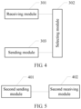
- FIG 4 is a schematic structural diagram of the user equipment 30 according to the embodiment of the present invention, and the user equipment 30 includes a receiving module 301, a selecting module 302, and a sending module 303, where the receiving module 301 may be implemented by a receiver in the user equipment 30 or a software module/unit or a hardware module/unit of the receiver of the user equipment 30, the selecting module 302 may be implemented by a processor in the user equipment 30 or a software module/unit or a hardware module/unit of the processor of the user equipment 30, and the sending module 303 may be implemented by a transmitter in the user equipment 30 or a software module/unit or a hardware module/unit of the transmitter of the user equipment 30.
- the receiving module 301 may be implemented by a receiver in the user equipment 30 or a software module/unit or a hardware module/unit of the receiver of the user equipment 30
- the selecting module 302 may be implemented by a processor in the user equipment 30 or a software module/unit or a hardware module/unit of the processor of the user equipment 30
- the receiving module 301 is configured to receive a reference signal sent by a base station.
- the reference signal sent by the base station may include a channel state information reference signal (Channel State Information Reference Signal, CSI RS), a demodulation reference signal (DeModulation RS, DM RS), a cell-specific reference signal (Cell-specific RS, CRS), or the like.
- the user equipment may obtain the reference signal by receiving an eNB notification, for example, by receiving radio resource control (Radio Resource Control, RRC) signaling or downlink control information (Down Control Information, DCI); or the user equipment obtains resource configuration of the reference signal based on a cell identity ID and then obtains the reference signal from a corresponding resource or subframe.
- RRC Radio Resource Control
- DCI Down Control Information
- the foregoing reference signal is corresponding to an antenna port; the reference signal may be corresponding to a physical antenna or an antenna array element, or may be corresponding to a virtual antenna, where the virtual antenna is a weighted combination of a physical antenna or an antenna array element.
- values of phases ⁇ and ⁇ may be flexibly selected according to a requirement of quantization precision.
- the foregoing structure divides antenna ports into two groups; a vector v may match channel characteristics corresponding to each antenna group of the two groups, and a phase between the two antenna port groups may be expressed by ⁇ .
- the foregoing structure may match actually deployed antenna configuration, for example, configuration of a four-port dual-polarized antenna or a uniform linear array antenna. Phases ⁇ and ⁇ are flexibly selected, which cannot only further improve quantization precision as required, but also achieve balance between overheads and the quantization precision.
- Column vectors of the precoding matrix W are orthogonal to each other, which further reduces inter-layer interference, thereby improving a transmission rate and spectral efficiency of a system.
- the foregoing codebook structure may match actually deployed antenna configuration, for example, configuration of a four-port dual-polarized antenna or a uniform linear array antenna; phases ⁇ and ⁇ are flexibly selected, which cannot only further improve quantization precision as required, but also achieve balance between overheads and the quantization precision.
- column vectors of the precoding matrix W are orthogonal to each other, which further reduces inter-layer interference.
- the selecting module 302 shown in FIG 4 may be specifically configured to acquire a channel estimation value based on the reference signal, and select a precoding matrix from a codebook according to the channel estimation value.
- this embodiment of the present invention sets no limitation on a specific manner of selecting a precoding matrix.
- a precoding matrix is selected from the codebook according to a predefined criterion, such as a criterion of channel capacity or throughput maximization, or a criterion of chordal distance minimization. Selecting a precoding matrix based on a predefined criterion is an existing technology, and details are not described herein again.
- the foregoing matrix structure may match actually deployed antenna configuration, for example, configuration of a four-port dual-polarized antenna or a uniform linear array antenna.
- Phases ⁇ and ⁇ are flexibly selected, which cannot only further improve quantization precision as required, but also achieve balance between overheads and the quantization precision.
- Column vectors of the precoding matrix W are orthogonal to each other, which further reduces inter-layer interference, thereby improving a transmission rate and spectral efficiency of a system.
- the sending module 303 is configured to send a precoding matrix indicator PMI to the base station, where the PMI is corresponding to the precoding matrix W selected by the selecting module 302.
- the user equipment may send the precoding matrix indicator PMI to the base station through a PUCCH or a PUSCH.
- the precoding matrix indicator PMI may include two indexes, that is, a first precoding matrix indicator PMI 1 and a first precoding matrix indicator PMI 2 , where the PMI 1 and the PMI 2 are respectively corresponding to index values i 1 and i 2 that are associated with the selected precoding matrix.
- the base station may obtain, according to the first precoding matrix indicator PMI 1 and the first precoding matrix indicator PMI 2 , the precoding matrix selected by the UE from the codebook.
- the PMI 1 and the PMI 2 have different time domain or frequency domain granularities, or are obtained based on different subframe periods or sub-band sizes.
- the precoding matrix indicator PMI 1 and the precoding matrix indicator PMI 2 respectively indicate channel characteristics with different periods or bandwidth, or are obtained based on different subframe periods or sub-band sizes. Further, the precoding matrix indicator PMI 1 and the precoding matrix indicator PMI 2 are sent to the base station in different time periods.
- the precoding matrix indicator PMI When a precoding matrix indicator PMI is sent to a base station, the precoding matrix indicator PMI may be sent to the base station by a user equipment through a PUCCH or a PUSCH.
- the precoding matrix W in this embodiment of the present invention may be a precoding matrix obtained after row or column displacement. For example, different antenna numbers correspondingly lead to row displacement of the precoding matrix.
- the user equipment may select a precoding matrix from a codebook based on a received reference signal, and send a precoding matrix indicator corresponding to the selected precoding matrix to the base station.
- the foregoing codebook structure may match actually deployed antenna configuration, for example, configuration of a four-port dual-polarized antenna or a uniform linear array antenna; phases ⁇ and ⁇ are flexibly selected, which cannot only further improve quantization precision as required, but also achieve balance between overheads and the quantization precision.
- column vectors of the precoding matrix W are orthogonal to each other, which further reduces inter-layer interference.
- division of functional modules is merely used as an example, and the foregoing functions may be allocated to different functional modules according to an actual requirement, for example, according to a corresponding hardware configuration requirement or for ease of software implementation; that is, an internal structure of the user equipment is divided into different functional modules, to complete all or some of the functions described above.
- corresponding functional modules in this embodiment may be implemented by corresponding hardware, or may be implemented by corresponding hardware by implementing corresponding software.
- the foregoing receiving module may be hardware that has a function of implementing the foregoing receiving a reference signal sent by a base station, such as a receiver, or may be a universal processor or another hardware device that can execute a corresponding computer program to complete the foregoing functions.
- the foregoing selecting module may be hardware that has a function of executing the foregoing selecting a precoding matrix W from a codebook based on a reference signal received by the receiving module (or receiver), such as a precoding matrix determiner, or may be a universal processor or another hardware device that can execute a corresponding computer program to complete the foregoing functions. (The principle of the foregoing description may be applicable to each embodiment provided in this specification.)
- FIG 5 is a schematic structural diagram of a base station according to an embodiment of the present invention.
- the base station includes a second sending module 401 and a second receiving module 402, where the second sending module 401 may be implemented by a transmitter in a base station 40 or a software module/unit or a hardware module/unit of the transmitter in the base station 40; the second receiving module 402 may be implemented by a receiver in the base station 40 or a software module/unit or a hardware module/unit of the receiver in the base station 40; or the second sending module 401 and the second receiving module 402 may be implemented by a processor in the base station 40 or a software module/unit or a hardware module/unit of the processor in the base station 40.
- the second sending module 401 is configured to send a reference signal to a user equipment UE.
- the reference signal may include a CSI RS, a DM RS, a CRS, or the like.
- the base station may instruct the UE to receive the reference signal through higher layer signaling such as RRC signaling or downlink control information DCI; or the base station sends the reference signal over a resource or a subframe of a corresponding reference signal based on a cell identity ID.
- This embodiment of the present invention sets no limitation on a specific manner of sending a reference signal.
- the foregoing reference signal is corresponding to an antenna port; the reference signal may be corresponding to a physical antenna or an antenna array element, or may be corresponding to a virtual antenna, where the virtual antenna is a weighted combination of a physical antenna or an antenna array element.
- values of phases ⁇ and ⁇ may be flexibly selected according to a requirement of quantization precision.
- the foregoing structure divides antenna ports into two groups; a vector v may match channel characteristics corresponding to each antenna group of the two groups, and a phase between the two antenna port groups may be expressed by ⁇ .
- the foregoing structure may match actually deployed antenna configuration, for example, configuration of a four-port dual-polarized antenna or a uniform linear array antenna. Phases ⁇ and ⁇ are flexibly selected, which cannot only further improve quantization precision as required, but also achieve balance between overheads and the quantization precision.
- Column vectors of the precoding matrix W are orthogonal to each other, which further reduces inter-layer interference, thereby improving a transmission rate and spectral efficiency of a system.
- the foregoing matrix structure may match actually deployed antenna configuration, for example, configuration of a four-port dual-polarized antenna or a uniform linear array antenna.
- Phases ⁇ and ⁇ are flexibly selected, which cannot only further improve quantization precision as required, but also achieve balance between overheads and the quantization precision.
- Column vectors of the precoding matrix W are orthogonal to each other, which further reduces inter-layer interference, thereby improving a transmission rate and spectral efficiency of a system.
- the base station may obtain, according to the PMI, the precoding matrix selected by the UE from the codebook.
- the precoding matrix indicator PMI may include two indexes, that is, a first precoding matrix indicator PMI 1 and a first precoding matrix indicator PMI 2 , where the PMI 1 and the PMI 2 are respectively corresponding to index values i 1 and i 2 that are associated with the selected precoding matrix.
- the base station may obtain, according to the PMI 1 and the PMI 2 , the precoding matrix selected by the UE from the codebook.
- the PMI may be received by a base station through a PUCCH or a PUSCH.
- the precoding matrix W in this embodiment of the present invention may be a precoding matrix obtained after row or column displacement. For example, different antenna numbers correspondingly lead to row displacement of the precoding matrix.
- the base station sends a reference signal and receives a precoding matrix indicator PMI sent by a UE, where the PMI is corresponding to a precoding matrix that is selected by the UE from a codebook based on the reference signal.
- the foregoing codebook structure may match actually deployed antenna configuration, for example, configuration of a four-port dual-polarized antenna or a uniform linear array antenna; phases ⁇ and ⁇ are flexibly selected, which cannot only further improve quantization precision as required, but also achieve balance between overheads and the quantization precision.
- column vectors of the precoding matrix W are orthogonal to each other, which further reduces inter-layer interference.
- An embodiment of the present invention further provides a computer storage medium, where the computer storage medium may store a program, and when the program is executed, the steps illustrated in FIG 1 or FIG 2 are performed.
- the program may be stored in a computer readable storage medium.
- the storage medium may include: a read-only memory (Read-Only Memory, ROM), a random access memory (Random Access Memory, RAM), a magnetic disk, or an optical disc.
- Embodiment 1 A method for feeding back channel state information, wherein the method comprises:
- Embodiment 4 The method according to embodiment 1, wherein the precoding matrix W is at least one matrix in the following matrix set: 1 12 1 1 1 1 e j ⁇ e j ⁇ ⁇ e j ⁇ 1 ⁇ 1 ⁇ 1 e j ⁇ ⁇ e j ⁇ e j ⁇ , 1 12 1 1 1 1 ⁇ e j ⁇ e j ⁇ ⁇ e j ⁇ 1 ⁇ 1 ⁇ 1 ⁇ e j ⁇ ⁇ e j ⁇ e j ⁇ , 1 12 1 1 1 1 e j ⁇ ⁇ e j ⁇ ⁇ e j ⁇ 1 1 ⁇ 1 e j ⁇ ⁇ e j ⁇ e j ⁇ , 1 12 1 1 1 1 ⁇ e j ⁇ e j ⁇ e j ⁇ e j ⁇ , 1 1 1 1 ⁇ e j ⁇ e j ⁇ e j ⁇ , 1 1 1 1 ⁇ e j ⁇ e j ⁇ e j ⁇
- Embodiment 5 The method according to embodiment 1, wherein the precoding matrix W is at least one matrix in the following matrix set: 1 4 1 1 1 1 1 1 e j ⁇ ⁇ e j ⁇ e j ⁇ ⁇ e j ⁇ 1 1 ⁇ 1 ⁇ 1 e j ⁇ ⁇ e j ⁇ ⁇ e j ⁇ e j ⁇ , 1 4 1 1 1 1 1 e j ⁇ ⁇ e j ⁇ e j ⁇ ⁇ e j ⁇ j ⁇ j ⁇ j je j ⁇ ⁇ je j ⁇ je j ⁇ or 1 4 1 1 1 1 1 1 e j ⁇ e j ⁇ ⁇ e j ⁇ ⁇ e j ⁇ 1 ⁇ 1 1 ⁇ 1 e j ⁇ ⁇ e j ⁇ ⁇ e j ⁇ e j ⁇ , 1 4 1 1 1 1 1 e j ⁇ e j ⁇ ⁇ e j ⁇ ⁇ e j ⁇ ⁇ j ⁇ j
- Embodiment 6 The method according to any one of embodiments 2 to 5, wherein the sending a precoding matrix indicator PMI to the base station comprises: sending a first precoding matrix indicator PMI 1 and a second precoding matrix indicator PMI 2 to the base station, wherein the first precoding matrix indicator PMI 1 and the second precoding matrix indicator PMI 2 are respectively used to indicate indexes i 1 and i 2 corresponding to the selected precoding matrix W.
- Embodiment 7 A method for feeding back channel state information, wherein the method comprises:
- Embodiment 10 The method according to embodiment 7, wherein the precoding matrix W is at least one matrix in the following matrix set: 1 12 1 1 1 1 e j ⁇ e j ⁇ ⁇ e j ⁇ 1 ⁇ 1 ⁇ 1 e j ⁇ ⁇ e j ⁇ e j ⁇ , 1 12 1 1 1 1 ⁇ e j ⁇ e j ⁇ ⁇ e j ⁇ 1 ⁇ 1 ⁇ 1 ⁇ e j ⁇ ⁇ e j ⁇ e j ⁇ , 1 12 1 1 1 1 e j ⁇ ⁇ e j ⁇ ⁇ e j ⁇ 1 1 ⁇ 1 e j ⁇ ⁇ e j ⁇ e j ⁇ , 1 12 1 1 1 1 ⁇ e j ⁇ e j ⁇ e j ⁇ e j ⁇ , 1 1 1 1 ⁇ e j ⁇ e j ⁇ e j ⁇ , 1 1 1 1 ⁇ e j ⁇ e j ⁇ e j ⁇
- Embodiment 11 The method according to embodiment 7, wherein the precoding matrix W is at least one matrix in the following matrix set: 1 4 1 1 1 1 1 1 e j ⁇ ⁇ e j ⁇ e j ⁇ ⁇ e j ⁇ 1 1 ⁇ 1 ⁇ 1 e j ⁇ ⁇ e j ⁇ ⁇ e j ⁇ e j ⁇ , 1 4 1 1 1 1 1 e j ⁇ ⁇ e j ⁇ e j ⁇ ⁇ e j ⁇ j ⁇ j ⁇ j je j ⁇ ⁇ je j ⁇ je j ⁇ or 1 4 1 1 1 1 1 1 e j ⁇ e j ⁇ ⁇ e j ⁇ ⁇ e j ⁇ 1 ⁇ 1 1 ⁇ 1 e j ⁇ ⁇ e j ⁇ ⁇ e j ⁇ e j ⁇ , 1 4 1 1 1 1 1 e j ⁇ e j ⁇ ⁇ e j ⁇ ⁇ e j ⁇ ⁇ j ⁇ ⁇
- Embodiment 12 The method according to any one of embodiments 8 to 11, wherein the receiving a precoding matrix indicator PMI sent by the UE comprises: receiving a first precoding matrix indicator PMI 1 and a second precoding matrix indicator PMI 2 that are sent by the UE, wherein the first precoding matrix indicator PMI 1 and the second precoding matrix indicator PMI 2 are respectively used to indicate indexes i 1 and i 2 corresponding to the selected precoding matrix.
- Embodiment 13 A user equipment, wherein the apparatus comprises:
- Embodiment 16 The user equipment according to embodiment 13, wherein the precoding matrix W is at least one matrix in the following matrix set: 1 12 1 1 1 1 e j ⁇ e j ⁇ ⁇ e j ⁇ 1 ⁇ 1 ⁇ 1 e j ⁇ ⁇ e j ⁇ e j ⁇ , 1 12 1 1 1 1 ⁇ e j ⁇ e j ⁇ ⁇ e j ⁇ 1 ⁇ 1 ⁇ 1 ⁇ e j ⁇ ⁇ e j ⁇ , 1 12 1 1 1 1 1 e j ⁇ ⁇ e j ⁇ ⁇ e j ⁇ 1 1 ⁇ 1 e j ⁇ ⁇ e j ⁇ e j ⁇ , 1 12 1 1 1 1 ⁇ e j ⁇ e j ⁇ e j ⁇ e j ⁇ , 1 1 1 1 ⁇ e j ⁇ e j ⁇ e j ⁇ , 1 1 1 1 ⁇ e j ⁇ e j ⁇ e j ⁇ , 1
- Embodiment 17 The user equipment according to embodiment 13, wherein the precoding matrix W is at least one matrix in the following matrix set: 1 4 1 1 1 1 1 1 e j ⁇ ⁇ e j ⁇ e j ⁇ ⁇ e j ⁇ 1 1 ⁇ 1 ⁇ 1 e j ⁇ ⁇ e j ⁇ ⁇ e j ⁇ e j ⁇ , 1 4 1 1 1 1 1 e j ⁇ ⁇ e j ⁇ e j ⁇ ⁇ e j ⁇ j ⁇ j ⁇ j je j ⁇ j ⁇ je j ⁇ or 1 4 1 1 1 1 1 1 e j ⁇ e j ⁇ ⁇ e j ⁇ ⁇ e j ⁇ 1 ⁇ 1 1 ⁇ 1 e j ⁇ ⁇ e j ⁇ ⁇ e j ⁇ e j ⁇ , 1 4 1 1 1 1 1 e j ⁇ e j ⁇ ⁇ e j ⁇ ⁇ e j ⁇ ⁇ j ⁇ ⁇ j
- Embodiment 18 The user equipment according to any one of embodiments 14 to 17, wherein the sending module is specifically configured to: send a first precoding matrix indicator PMI 1 and a second precoding matrix indicator PMI 2 to the base station, wherein the first precoding matrix indicator PMI 1 and the second precoding matrix indicator PMI 2 are respectively used to indicate indexes i 1 and i 2 corresponding to the selected precoding matrix.
- Embodiment 19 A base station, wherein the base station comprises:
- Embodiment 22 The base station according to embodiment 19, wherein the precoding matrix W is at least one matrix in the following matrix set: 1 12 1 1 1 1 e j ⁇ e j ⁇ ⁇ e j ⁇ 1 ⁇ 1 ⁇ 1 e j ⁇ ⁇ e j ⁇ e j ⁇ , 1 12 1 1 1 1 ⁇ e j ⁇ e j ⁇ ⁇ e j ⁇ 1 ⁇ 1 ⁇ 1 ⁇ e j ⁇ ⁇ e j ⁇ , 1 12 1 1 1 1 e j ⁇ ⁇ e j ⁇ ⁇ e j ⁇ 1 1 ⁇ 1 e j ⁇ ⁇ e j ⁇ e j ⁇ , 1 12 1 1 1 1 ⁇ e j ⁇ e j ⁇ e j ⁇ , 1 1 1 1 ⁇ e j ⁇ e j ⁇ e j ⁇ , 1 1 1 1 ⁇ e j ⁇ e j ⁇ e j ⁇ , 1 1 1 1 ⁇
- Embodiment 23 The base station according to embodiment 19, wherein the precoding matrix W is at least one matrix in the following matrix set: 1 4 1 1 1 1 1 1 e j ⁇ ⁇ e j ⁇ e j ⁇ ⁇ e j ⁇ 1 1 ⁇ 1 ⁇ 1 e j ⁇ ⁇ e j ⁇ ⁇ e j ⁇ e j ⁇ , 1 4 1 1 1 1 1 e j ⁇ ⁇ e j ⁇ e j ⁇ ⁇ e j ⁇ j ⁇ j ⁇ j je j ⁇ j ⁇ je j ⁇ or 1 4 1 1 1 1 1 1 e j ⁇ e j ⁇ ⁇ e j ⁇ ⁇ e j ⁇ 1 ⁇ 1 1 ⁇ 1 e j ⁇ ⁇ e j ⁇ ⁇ e j ⁇ e j ⁇ , 1 4 1 1 1 1 1 e j ⁇ e j ⁇ ⁇ e j ⁇ ⁇ e j ⁇ , 1 4 1 1 1 1
- Embodiment 24 The base station according to any one of embodiments 20 to 23, wherein the second receiving module is specifically configured to: receive a first precoding matrix indicator PMI 1 and a second precoding matrix indicator PMI 2 that are sent by a user equipment to the base station, wherein the first precoding matrix indicator PMI 1 and the second precoding matrix indicator PMI 2 are respectively used to indicate indexes i 1 and i 2 corresponding to the selected precoding matrix.
- the second receiving module is specifically configured to: receive a first precoding matrix indicator PMI 1 and a second precoding matrix indicator PMI 2 that are sent by a user equipment to the base station, wherein the first precoding matrix indicator PMI 1 and the second precoding matrix indicator PMI 2 are respectively used to indicate indexes i 1 and i 2 corresponding to the selected precoding matrix.
- Embodiment 25 A computer storage medium, wherein the computer storage medium may store a program, and when the program is executed, a step in any one of embodiments 1 to 7 or a step in any one of embodiments 8 to 12 is performed.
Abstract
Description
- The present invention relates to the field of mobile communications, and in particular, to a method for feeding back channel state information, a user equipment, and a base station.
- A multiple-input multiple-output (Multiple Input Multiple Output, MIMO) wireless communication system may obtain diversity and array gains by using beam forming (BF, Beam Forming) and receive signal combination, or by using precoding and receive signal combination. Typically, a wireless communication system using BF or precoding may be generally expressed as y = H V s + n , where y is a received signal vector, H is a channel matrix, V is a precoding matrix, s is a transmitted symbol vector, and n is measurement noise. Generally, optimal precoding requires that channel state information (Channel State Information, CSI) is fully known to a transmitter, and a commonly used method is that a user equipment (User Equipment, UE) performs quantization on instantaneous CSI and feeds back the quantized instantaneous CSI to a node B (NodeB). CSI fed back by an existing Long Term Evolution Release 8 (Long Term Evolution Release 8, LTE R8) system includes a rank indicator (Rank Indicator, RI), a precoding matrix indicator (Precoding Matrix Indicator, PMI), a channel quality indicator (Channel Quality Indicator, CQI), and the like, where the RI and the PMI respectively indicate the number of used layers and a precoding matrix. Generally, a set of used precoding matrices is called a codebook, and each precoding matrix in the codebook is called a code word. A codebook of LTE R8 is mainly designed for single user multiple-input multiple-output (Single User Multiple Input Multiple Output, SU-MIMO), where a precoding matrix or a code word is restrained by 8 phase shift keying (8 Phase Shift Keying, 8PSK), and precision of spatial quantization is limited. For a transmission manner in which precision of spatial quantization is sensitive, such as multiple user multiple-input multiple-output (Multiple User Multiple Input Multiple Output, MU-MIMO), performance of the transmission manner is severely limited by the codebook of LTE R8. To meet a higher system requirement, a 3rd Generation Partnership Project (the 3rd Generation Partnership Project, 3GPP) LTE system needs to further enhance performance of MU-MIMO. In addition, a coordinated multiple-points (Coordinated Multiple-Points, CoMP) transmission technology is introduced (currently, CoMP is based on a single-cell feedback). The foregoing two technologies both have a higher requirement on feedback performance.
- In the prior art, a single codebook is used to feed back RIs and PMIs. By using four antennas as an example, a correspondence between an RI, a PMI, and each code word in the codebook is shown in the following Table 1:
Table 1 PMI un RI 1 2 3 4 0 
W 0 {1} 


1 
W 1 {1} 


2 
W 2 {1} 


3 
W 3 {1} 


4 
W 4 {1} 


5 
W 5 {1} 


6 
W 6 {1} 


7 
W 6 {1} 


8 
W 8 {1} 


9 
W 6 {1} 


10 


11 


12 


13 


14 


15 


- Wn {s} indicates a matrix that includes a column set {s} of a matrix

- It can be learned from thorough investigation on the foregoing Table 1 that, in a precoding matrix obtained based on

- Embodiments of the present invention provide a method for feeding back channel state information, a user equipment, and a base station, to improve feedback precision of channel state information.
- According to one aspect, an embodiment of the present invention provides a method for feeding back channel state information, where the method includes:
- receiving a reference signal sent by a base station;
- selecting a precoding matrix W from a codebook according to the reference signal, where a column vector of the precoding matrix W may be expressed as α[v e jφ v] T , v = [1 ejθ ], where α is a constant, θ and φ are phases, and [ ] T indicates transposing of a matrix or vector; and
- sending a precoding matrix indicator PMI to the base station, where the PMI is corresponding to the selected precoding matrix W.
- According to another aspect, an embodiment of the present invention further provides a method for feeding back channel state information, where the method includes:
- sending a reference signal to a user equipment UE;
- receiving a precoding matrix indicator PMI sent by the UE, where the PMI is corresponding to a precoding matrix W that is selected by the UE from a codebook based on the reference signal, and a column vector of the precoding matrix W may be expressed as α[v e jφ v] T , v = [1 ejθ ], where α is a constant, θ and φ are phases, and [ ] T indicates transposing of a matrix or vector.
- Another embodiment of the present invention provides a user equipment, where the user equipment includes:
- a receiving module, configured to receive a reference signal sent by a base station;
- a selecting module, configured to select a precoding matrix W from a codebook based on the reference signal received by the receiving module, where a column vector of the precoding matrix W may be expressed as α[v ejφ v] T , v = [1 ejθ ], where α is a constant, θ and φ are phases, and [ ] T indicates transposing of a matrix or vector; and
- a sending module, configured to send a precoding matrix indicator PMI to the base station, where the PMI is corresponding to the precoding matrix W selected by the selecting module.
- Correspondingly, an embodiment of the present invention further provides a base station, where the base station includes:
- a second sending module, configured to send a reference signal to a user equipment UE;
- a second receiving module, configured to receive a precoding matrix indicator PMI sent by the UE, where the PMI is corresponding to a precoding matrix W that is selected by the UE from a codebook based on the reference signal, and a column vector of the precoding matrix W may be expressed as α[v ejφ v] T , v = [1 ejθ ], where α is a constant, θ and φ are phases, and [ ] T indicates transposing of a matrix or vector.
- Correspondingly, another embodiment of the present invention provides a computer storage medium, where the computer storage medium may store a program, and when the program is executed, a step in the foregoing method embodiments is performed.
- It can be learned from the foregoing embodiments of the present invention that, a user equipment may select a precoding matrix from a codebook based on a received reference signal, and send a precoding matrix indicator corresponding to the selected precoding matrix W to the base station, where the codebook includes at least one precoding matrix W, and a column vector of the precoding matrix W may be expressed as α[v ejφ v] T , v = [1 ejθ ], where α is a constant, θ and φ are phases, and [ ] T indicates transposing of a matrix or vector. The foregoing codebook structure may match actually deployed antenna configuration, for example, configuration of a four-port dual-polarized antenna or a uniform linear array antenna; phases θ and φ are flexibly selected, which cannot only further improve quantization precision as required, but also achieve balance between overheads and the quantization precision. In addition, column vectors of the precoding matrix W are orthogonal to each other, which further reduces inter-layer interference. After the user equipment feeds back the precoding matrix indicator corresponding to the precoding matrix W to the base station, the base station performs precoding on a sent signal according to the fed back precoding matrix indicator, which can improve precoding precision, thereby improving a data transmission rate and system throughput.
- To describe the technical solutions in the embodiments of the present invention more clearly, the following briefly introduces the accompanying drawings required for describing the prior art or the embodiments. Apparently, the accompanying drawings in the following description show merely some embodiments of the present invention, and a person skilled in the art may still derive other drawings from these accompanying drawings.
-
FIG 1 is a schematic flowchart of a method for feeding back channel state information according to an embodiment of the present invention; -
FIG 2 is a schematic flowchart of a method for feeding back channel state information according to another embodiment of the present invention; -
FIG 3 is a schematic structural diagram of a system for feeding back channel state information according to an embodiment of the present invention; -
FIG 4 is a schematic structural diagram of a user equipment according to an embodiment of the present invention; and -
FIG 5 is a schematic structural diagram of a base station according to an embodiment of the present invention. - The following clearly and completely describes the technical solutions in the embodiments of the present invention with reference to the accompanying drawings in the embodiments of the present invention. Apparently, the described embodiments are merely some but not all of the embodiments of the present invention. All other embodiments obtained by a person skilled in the art based on the embodiments of the present invention shall fall within the protection scope of the present invention.
- Referring to
FIG 1, FIG 1 is a schematic flowchart of a method for feeding back channel state information according to an embodiment of the present invention, and an execution body of the method may be a user equipment (User Equipment, UE) of an LTE system, for example, may be a user equipment (User Equipment, UE), a mobile station (Mobile Station, MS), or a relay (Relay) (hereinafter referred to as a UE). - The following describes the method illustrated in
FIG 1 , which mainly includes step S101, step S102, and step S103. - Step S101: Receive a reference signal sent by a base station.
- In this embodiment of the present invention, the reference signal sent by the base station may include a channel state information reference signal (Channel State Information Reference Signal, CSI RS), a demodulation reference signal (DeModulation RS, DM RS), a cell-specific reference signal (Cell-specific RS, CRS), or the like. The user equipment may obtain the reference signal by receiving an eNB notification, for example, by receiving radio resource control (Radio Resource Control, RRC) signaling or downlink control information (Down Control Information, DCI); or the user equipment obtains resource configuration of the reference signal based on a cell identity ID and then obtains the reference signal from a corresponding resource or subframe. This embodiment of the present invention sets no limitation on a specific manner of receiving a reference signal.
- It should be understood that the foregoing reference signal is corresponding to an antenna port; the reference signal may be corresponding to a physical antenna or an antenna array element, or may be corresponding to a virtual antenna, where the virtual antenna is a weighted combination of a physical antenna or an antenna array element.
- Step S102: Select a precoding matrix W from a codebook based on the reference signal, where a column vector of the precoding matrix W may be expressed as α[v e jφ v] T , v = [1 ejθ ], where α is a constant, θ and φ are phases, and [ ] T indicates transposing of a matrix or vector.
- Specifically, values of phases θ and φ may be flexibly selected according to a requirement of quantization precision.
- Further, column vectors of the precoding matrix W may be orthogonal to each other, that is, W meets W H W = α 2 I, where W H indicates a conjugate transpose of the matrix W, and I is an identity matrix. The foregoing structure divides antenna ports into two groups; a vector v may match channel characteristics corresponding to each antenna group of the two groups, and a phase between the two antenna port groups may be expressed by φ. The foregoing structure may match actually deployed antenna configuration, for example, configuration of a four-port dual-polarized antenna or a uniform linear array antenna. Phases θ and φ are flexibly selected, which cannot only further improve quantization precision as required, but also achieve balance between overheads and the quantization precision. Column vectors of the precoding matrix W are orthogonal to each other, which further reduces inter-layer interference, thereby improving a transmission rate and spectral efficiency of a system.
- It should be noted that, a codebook in this embodiment of the present invention may be a codebook subset. The codebook subset may be predefined; the codebook subset may be reported by a user equipment to a base station (eNB), and then the base station (eNB) determines the codebook subset based on reporting of the user equipment and notifies the user equipment of the determined codebook subset; or the codebook subset may be a codebook subset determined and reported by a user equipment, for example, a recently reported codebook subset.
- Specifically, in step 102, the selecting a precoding matrix from a codebook based on the reference signal may include: acquiring, by a UE, a channel estimation value based on the reference signal; and selecting, by the UE, a precoding matrix from a codebook based on the channel estimation value.
- It should be noted that, this embodiment of the present invention sets no limitation on a specific manner of selecting a precoding matrix. Optionally, a precoding matrix is selected from the codebook according to a predefined criterion, such as a criterion of channel capacity or throughput maximization, or a criterion of chordal distance minimization. Selecting a precoding matrix based on a predefined criterion is an existing technology, and details are not described herein again.
- As an embodiment of the present invention, the precoding matrix W is at least one matrix in the following matrix set:


- It can be learned from investigation on the matrix set (1) to which the foregoing precoding matrix W belongs that, the foregoing precoding matrix W may match actually deployed antenna configuration. In addition, a granularity of a value of θ is

- As another embodiment of the present invention, the precoding matrix W is at least one matrix in the following matrix set:


- It can be learned from investigation on the matrix set (2) or (2') to which the foregoing precoding matrix W belongs that, the foregoing precoding matrix W may match actually deployed antenna configuration. Because a granularity of a value of θ is

- As another embodiment of the present invention, the precoding matrix W is at least one matrix in the following matrix set:


- Similarly, it can be learned from investigation on the matrix set (3) to which the foregoing precoding matrix W belongs that, the foregoing precoding matrix W may match actually deployed antenna configuration. Because a granularity of a value of θ is

- As another embodiment of the present invention, the precoding matrix W is at least one matrix in the following matrix set:


- Similarly, it can be learned from investigation on the matrix set (4) or (5) to which the foregoing precoding matrix W belongs that, the foregoing precoding matrix W may match actually deployed antenna configuration. Because a granularity of a value of θ is

- Step S103: Send a precoding matrix indicator PMI to the base station, where the PMI is corresponding to the selected precoding matrix W.
- In this embodiment of the present invention, the precoding matrix indicator PMI may include only one specific value, and the PMI directly indicates the selected precoding matrix. For example, altogether 256 different precoding matrices may be selected from the matrix set (1) or (2), and then PMI = 0, ..., 255 may be used to respectively indicate the precoding matrices whose index values are 0, 1, .. , 255. Therefore, as an embodiment of the present invention in which a precoding matrix indicator PMI is sent to the base station and the PMI is corresponding to the selected precoding matrix, the precoding matrix indicator PMI may be an index value corresponding to a precoding matrix W in a codebook. Because a base station side also has the codebook, the base station may obtain, according to the PMI, a precoding matrix selected by a UE from the codebook.
- According to another aspect, because the index values i 1 and i 2 can uniquely determine a precoding matrix W, as another embodiment of the present invention in which a precoding matrix indicator PMI is sent to the base station and the PMI is corresponding to the selected precoding matrix, a first precoding matrix indicator PMI1 and a first precoding matrix indicator PMI2 may be sent to the base station, and are respectively corresponding to the index values i 1 and i 2 that are associated with the selected precoding matrix. Because a base station side also has the codebook, the base station may obtain, according to the first precoding matrix indicator PMI1 and the first precoding matrix indicator PMI2, a precoding matrix selected by a UE from the codebook. For ease of the following description, a precoding matrix indicator PMI1 and a precoding matrix indicator PMI2 are respectively used to indicate corresponding precoding matrix indicators indicated by i 1 and i 2. In this embodiment of the present invention, the PMI1 and the PMI2 have different time domain or frequency domain granularities, or are obtained based on different subframe periods or sub-band sizes. For example, the precoding matrix indicator PMI1 and the precoding matrix indicator PMI2 respectively indicate channel characteristics with different periods or bandwidth, or are obtained based on different subframe periods or sub-band sizes. Further, the precoding matrix indicator PMI1 and the precoding matrix indicator PMI2 are sent to the base station in different time periods.
- When a precoding matrix indicator PMI is sent to a base station, the precoding matrix indicator PMI may be sent to the base station by a user equipment through a physical uplink control channel (Physical Uplink Control Channel, PUCCH) or a physical uplink shared channel (Physical Uplink Shared Channel, PUSCH). It should be noted that, the precoding matrix W in this embodiment of the present invention may be a precoding matrix obtained after row or column displacement. For example, different antenna numbers correspondingly lead to row displacement of the precoding matrix.
- It can be learned from the foregoing method for feeding back channel state information according to this embodiment of the present invention that, a user equipment may select a precoding matrix from a codebook based on a received reference signal, and send a precoding matrix indicator corresponding to the selected precoding matrix to the base station. The codebook includes at least one precoding matrix W, and a column vector of the precoding matrix W may be expressed as α[v e jφ v] T , v = [1 ejθ ], where α is a constant, θ and φ are phases, and [ ] T indicates transposing of a matrix or vector. The foregoing codebook structure may match actually deployed antenna configuration, for example, configuration of a four-port dual-polarized antenna or a uniform linear array antenna; phases θ and φ are flexibly selected, which cannot only further improve quantization precision as required, but also achieve balance between overheads and the quantization precision. In addition, column vectors of the precoding matrix W are orthogonal to each other, which further reduces inter-layer interference. After the user equipment feeds back the precoding matrix indicator corresponding to the precoding matrix W to the base station, the base station performs precoding on a sent signal according to the fed back precoding matrix indicator, which improves system throughput.
- With reference to
FIG 1 , the foregoing embodiment describes in detail a method for feeding back channel state information according to the embodiment of the present invention from a perspective of a UE; with reference toFIG 2 , the following describes a method for feeding back channel state information according to an embodiment of the present invention from a perspective of a base station. -
FIG 2 is a method for feeding back channel state information according to another embodiment of the present invention. The method inFIG 2 is implemented by a base station, which, for example, may be a node B (NodeB), an access point (Access Point, AP), a transmission point (Transmission Point, TP), an evolved node B (Evolved Node B, eNB), or a relay (Relay). - It should be understood that description about a UE side in interaction between a UE and a base station, and related characteristics and functions of the UE and the base station is corresponding to description about a base station side. For brevity, details are not described herein again.
- The following describes a method illustrated in
FIG 2 , which mainly includes step 5201 and step S202. Detailed description is as follows: - Step S201: Send a reference signal to a user equipment UE.
- Specifically, the reference signal may include a CSI RS, a DM RS, a CRS, or the like. The base station may instruct the UE to receive the reference signal through higher layer signaling such as RRC signaling or downlink control information DCI; or the base station sends the reference signal over a resource or a subframe of a corresponding reference signal based on a cell identity ID. This embodiment of the present invention sets no limitation on a specific manner of sending a reference signal.
- Step S202: Receive a precoding matrix indicator PMI sent by the UE, where the PMI is corresponding to a precoding matrix W that is selected by the UE from a codebook based on the reference signal, and a column vector of the precoding matrix W may be expressed as α[v e jφ v] T , v = [1 ejθ ], where α is a constant, θ and φ are phases, and [ ] T indicates transposing of a matrix or vector.
- Specifically, values of phases θ and φ may be flexibly selected according to a requirement of quantization precision.
- Further, column vectors of the precoding matrix W may be orthogonal to each other, that is, W meets W H W = α 2 I, , where W H indicates a conjugate transpose of the matrix W, and I is an identity matrix. The foregoing structure divides antenna ports into two groups; a vector v may match channel characteristics corresponding to each antenna group of the two groups, and a phase between the two antenna port groups may be expressed by .
- As an embodiment of the present invention, the precoding matrix W is at least one matrix in the matrix set shown in the expression (1), where


- As another embodiment of the present invention, the precoding matrix W is at least one matrix in the matrix set shown in the expression (2) or (2'), where


- As another embodiment of the present invention, the precoding matrix W is at least one matrix in the matrix set shown in the expression (3), where


- As another embodiment of the present invention, the precoding matrix W is at least one matrix in the matrix set shown in the expression (4) or (5), where


- It can be learned from investigation on the foregoing precoding matrix W that, the foregoing matrix structure may match actually deployed antenna configuration, for example, configuration of a four-port dual-polarized antenna or a uniform linear array antenna. Phases θ and φ are flexibly selected, which cannot only further improve quantization precision as required, but also achieve balance between overheads and the quantization precision. Column vectors of the precoding matrix W are orthogonal to each other, which further reduces inter-layer interference, thereby improving a transmission rate and spectral efficiency of a system.
- The codebook is known to both the base station and the UE. As another embodiment of the present invention, the precoding matrix indicator PMI may include only one specific value, and the PMI directly indicates the selected precoding matrix. For example, altogether 256 different precoding matrices may be selected from the matrix set (1) or (2), and then PMI = 0, .. , 255 may be used to respectively indicate the precoding matrices whose index values are 0, 1, ..., 255. In this case, the base station may obtain, according to the PMI, the precoding matrix selected by the UE from the codebook.
- As another embodiment of the present invention, the precoding matrix indicator PMI may include two indexes, that is, a first precoding matrix indicator PMI1 and a first precoding matrix indicator PMI2, where the PMI1 and the PMI2 are respectively corresponding to index values i 1 and i 2 that are associated with the selected precoding matrix. The base station may obtain, according to the PMI1 and the PMI2, the precoding matrix selected by the UE from the codebook.
- When a precoding matrix indicator PMI sent by a user equipment UE is received, the PMI may be received by a base station through a PUCCH or a PUSCH. It should be noted that, the precoding matrix W in this embodiment of the present invention may be a precoding matrix obtained after row or column displacement. For example, different antenna numbers correspondingly lead to row displacement of the precoding matrix.
- It can be learned from the foregoing method for feeding back channel state information according to this embodiment of the present invention that, a base station sends a reference signal and receives a precoding matrix indicator PMI sent by a UE, where the PMI is corresponding to a precoding matrix that is selected by the UE from a codebook based on the reference signal. The codebook includes at least one precoding matrix W, and a column vector of the precoding matrix W may be expressed as α[v e jφ v] T , v = [1 ejθ ], where α is a constant, θ and φ are phases, and [ ] T indicates transposing of a matrix or vector. The foregoing codebook structure may match actually deployed antenna configuration, for example, configuration of a four-port dual-polarized antenna or a uniform linear array antenna; phases θ and φ are flexibly selected, which cannot only further improve quantization precision as required, but also achieve balance between overheads and the quantization precision. In addition, column vectors of the precoding matrix W are orthogonal to each other, which further reduces inter-layer interference. After the user equipment feeds back the precoding matrix indicator corresponding to the precoding matrix W to the base station, the base station performs precoding on a sent signal according to the fed back precoding matrix indicator, which improves system throughput.
- The following describes in detail a system for feeding back channel state information, a user equipment, and a base station according to the present invention. Referring to
FIG 3, FIG 3 is a schematic diagram of structural composition of a system for feeding back channel state information according to an embodiment of the present invention. The system according to this embodiment of the present invention includes auser equipment 30 and abase station 40. A structure of theuser equipment 30 is shown inFIG 4 , and a structure of thebase station 40 is shown inFIG 5 . - Referring to
FIG 4, FIG 4 is a schematic structural diagram of theuser equipment 30 according to the embodiment of the present invention, and theuser equipment 30 includes a receivingmodule 301, a selectingmodule 302, and a sendingmodule 303, where the receivingmodule 301 may be implemented by a receiver in theuser equipment 30 or a software module/unit or a hardware module/unit of the receiver of theuser equipment 30, the selectingmodule 302 may be implemented by a processor in theuser equipment 30 or a software module/unit or a hardware module/unit of the processor of theuser equipment 30, and the sendingmodule 303 may be implemented by a transmitter in theuser equipment 30 or a software module/unit or a hardware module/unit of the transmitter of theuser equipment 30. - The receiving
module 301 is configured to receive a reference signal sent by a base station. The reference signal sent by the base station may include a channel state information reference signal (Channel State Information Reference Signal, CSI RS), a demodulation reference signal (DeModulation RS, DM RS), a cell-specific reference signal (Cell-specific RS, CRS), or the like. The user equipment may obtain the reference signal by receiving an eNB notification, for example, by receiving radio resource control (Radio Resource Control, RRC) signaling or downlink control information (Down Control Information, DCI); or the user equipment obtains resource configuration of the reference signal based on a cell identity ID and then obtains the reference signal from a corresponding resource or subframe. This embodiment of the present invention sets no limitation on a specific manner of receiving a reference signal. - It should be understood that the foregoing reference signal is corresponding to an antenna port; the reference signal may be corresponding to a physical antenna or an antenna array element, or may be corresponding to a virtual antenna, where the virtual antenna is a weighted combination of a physical antenna or an antenna array element.
- The selecting
module 302 is configured to select a precoding matrix W from a codebook based on the reference signal received by the receivingmodule 301, where a column vector of the precoding matrix W may be expressed as α[v e jφ v] T , v = [1 ejθ ], where α is a constant, θ and φ are phases, and [ ] T indicates transposing of a matrix or vector. - Specifically, values of phases θ and φ may be flexibly selected according to a requirement of quantization precision.
- Further, column vectors of the precoding matrix W may be orthogonal to each other, that is, W meets W H W = α 2 I, , where W H indicates a conjugate transpose of the matrix W, and I is an identity matrix. The foregoing structure divides antenna ports into two groups; a vector v may match channel characteristics corresponding to each antenna group of the two groups, and a phase between the two antenna port groups may be expressed by φ. The foregoing structure may match actually deployed antenna configuration, for example, configuration of a four-port dual-polarized antenna or a uniform linear array antenna. Phases θ and φ are flexibly selected, which cannot only further improve quantization precision as required, but also achieve balance between overheads and the quantization precision. Column vectors of the precoding matrix W are orthogonal to each other, which further reduces inter-layer interference, thereby improving a transmission rate and spectral efficiency of a system.
- It can be learned from the foregoing embodiment of the present invention that, a user equipment may select a precoding matrix from a codebook based on a received reference signal, and send a precoding matrix indicator corresponding to the selected precoding matrix W to the base station, where the codebook includes at least one precoding matrix W, and a column vector of the precoding matrix W may be expressed as α[v ejφ v] T , v = [1 ejθ ], where α is a constant, θ and φ are phases, and [ ] T indicates transposing of a matrix or vector. The foregoing codebook structure may match actually deployed antenna configuration, for example, configuration of a four-port dual-polarized antenna or a uniform linear array antenna; phases θ and φ are flexibly selected, which cannot only further improve quantization precision as required, but also achieve balance between overheads and the quantization precision. In addition, column vectors of the precoding matrix W are orthogonal to each other, which further reduces inter-layer interference. After the user equipment feeds back the precoding matrix indicator corresponding to the precoding matrix W to the base station, the base station performs precoding on a sent signal according to the fed back precoding matrix indicator, which can improve precoding precision, thereby improving a data transmission rate and system throughput.
- The selecting
module 302 shown inFIG 4 may be specifically configured to acquire a channel estimation value based on the reference signal, and select a precoding matrix from a codebook according to the channel estimation value. - It should be noted that, this embodiment of the present invention sets no limitation on a specific manner of selecting a precoding matrix. Optionally, a precoding matrix is selected from the codebook according to a predefined criterion, such as a criterion of channel capacity or throughput maximization, or a criterion of chordal distance minimization. Selecting a precoding matrix based on a predefined criterion is an existing technology, and details are not described herein again.
- As an embodiment of the present invention, the precoding matrix W is at least one matrix in the matrix set shown in the expression (1), where


- As another embodiment of the present invention, the precoding matrix W is at least one matrix in the matrix set shown in the expression (2) or (2'), where


- As another embodiment of the present invention, the precoding matrix W is at least one matrix in the matrix set shown in the expression (3), where


- As another embodiment of the present invention, the precoding matrix W is at least one matrix in the matrix set shown in the expression (4) or (5), where


- It can be learned from investigation on the foregoing precoding matrix W that, the foregoing matrix structure may match actually deployed antenna configuration, for example, configuration of a four-port dual-polarized antenna or a uniform linear array antenna. Phases θ and φ are flexibly selected, which cannot only further improve quantization precision as required, but also achieve balance between overheads and the quantization precision. Column vectors of the precoding matrix W are orthogonal to each other, which further reduces inter-layer interference, thereby improving a transmission rate and spectral efficiency of a system.
- The sending
module 303 is configured to send a precoding matrix indicator PMI to the base station, where the PMI is corresponding to the precoding matrix W selected by the selectingmodule 302. The user equipment may send the precoding matrix indicator PMI to the base station through a PUCCH or a PUSCH. - As an embodiment of the present invention, the precoding matrix indicator PMI may include only one specific value, and the PMI directly indicates the selected precoding matrix. For example, altogether 256 different precoding matrices may be selected from the matrix set (1) or (2), and then PMI = 0, ..., 255 may be used to respectively indicate the precoding matrices whose index values are 0, 1, ..., 255. Therefore, as an embodiment of the present invention in which a precoding matrix indicator PMI is sent to the base station and the PMI is corresponding to the selected precoding matrix, the precoding matrix indicator PMI may be an index value corresponding to a precoding matrix W in a codebook. Because a base station side also has the codebook, the base station may obtain, according to the PMI, the precoding matrix selected by the UE from the codebook.
- As another embodiment of the present invention, the precoding matrix indicator PMI may include two indexes, that is, a first precoding matrix indicator PMI1 and a first precoding matrix indicator PMI2, where the PMI1 and the PMI2 are respectively corresponding to index values i 1 and i 2 that are associated with the selected precoding matrix. The base station may obtain, according to the first precoding matrix indicator PMI1 and the first precoding matrix indicator PMI2, the precoding matrix selected by the UE from the codebook.
- In this embodiment of the present invention, the PMI1 and the PMI2 have different time domain or frequency domain granularities, or are obtained based on different subframe periods or sub-band sizes. For example, the precoding matrix indicator PMI1 and the precoding matrix indicator PMI2 respectively indicate channel characteristics with different periods or bandwidth, or are obtained based on different subframe periods or sub-band sizes. Further, the precoding matrix indicator PMI1 and the precoding matrix indicator PMI2 are sent to the base station in different time periods.
- When a precoding matrix indicator PMI is sent to a base station, the precoding matrix indicator PMI may be sent to the base station by a user equipment through a PUCCH or a PUSCH. It should be noted that, the precoding matrix W in this embodiment of the present invention may be a precoding matrix obtained after row or column displacement. For example, different antenna numbers correspondingly lead to row displacement of the precoding matrix.
- It can be learned from the foregoing user equipment according to this embodiment of the present invention that, the user equipment may select a precoding matrix from a codebook based on a received reference signal, and send a precoding matrix indicator corresponding to the selected precoding matrix to the base station. The codebook includes at least one precoding matrix W, and a column vector of the precoding matrix W may be expressed as α[v e jφ v] T , v = [1 ejθ ], where α is a constant, θ and φ are phases, and [ ] T indicates transposing of a matrix or vector.
- The foregoing codebook structure may match actually deployed antenna configuration, for example, configuration of a four-port dual-polarized antenna or a uniform linear array antenna; phases θ and φ are flexibly selected, which cannot only further improve quantization precision as required, but also achieve balance between overheads and the quantization precision. In addition, column vectors of the precoding matrix W are orthogonal to each other, which further reduces inter-layer interference. After the user equipment feeds back the precoding matrix indicator corresponding to the precoding matrix W to the base station, the base station performs precoding on a sent signal according to the fed back precoding matrix indicator, which improves system throughput.
- It should be noted that, in the foregoing implementation manner of the user equipment, division of functional modules is merely used as an example, and the foregoing functions may be allocated to different functional modules according to an actual requirement, for example, according to a corresponding hardware configuration requirement or for ease of software implementation; that is, an internal structure of the user equipment is divided into different functional modules, to complete all or some of the functions described above. In addition, in an actual application, corresponding functional modules in this embodiment may be implemented by corresponding hardware, or may be implemented by corresponding hardware by implementing corresponding software. For example, the foregoing receiving module may be hardware that has a function of implementing the foregoing receiving a reference signal sent by a base station, such as a receiver, or may be a universal processor or another hardware device that can execute a corresponding computer program to complete the foregoing functions. For another example, the foregoing selecting module may be hardware that has a function of executing the foregoing selecting a precoding matrix W from a codebook based on a reference signal received by the receiving module (or receiver), such as a precoding matrix determiner, or may be a universal processor or another hardware device that can execute a corresponding computer program to complete the foregoing functions. (The principle of the foregoing description may be applicable to each embodiment provided in this specification.)
- Referring to
FIG 5, FIG 5 is a schematic structural diagram of a base station according to an embodiment of the present invention. The base station includes asecond sending module 401 and asecond receiving module 402, where thesecond sending module 401 may be implemented by a transmitter in abase station 40 or a software module/unit or a hardware module/unit of the transmitter in thebase station 40; thesecond receiving module 402 may be implemented by a receiver in thebase station 40 or a software module/unit or a hardware module/unit of the receiver in thebase station 40; or thesecond sending module 401 and thesecond receiving module 402 may be implemented by a processor in thebase station 40 or a software module/unit or a hardware module/unit of the processor in thebase station 40. - The
second sending module 401 is configured to send a reference signal to a user equipment UE. - Specifically, the reference signal may include a CSI RS, a DM RS, a CRS, or the like. The base station may instruct the UE to receive the reference signal through higher layer signaling such as RRC signaling or downlink control information DCI; or the base station sends the reference signal over a resource or a subframe of a corresponding reference signal based on a cell identity ID. This embodiment of the present invention sets no limitation on a specific manner of sending a reference signal.
- It should be understood that the foregoing reference signal is corresponding to an antenna port; the reference signal may be corresponding to a physical antenna or an antenna array element, or may be corresponding to a virtual antenna, where the virtual antenna is a weighted combination of a physical antenna or an antenna array element.
- The
second receiving module 402 is configured to receive a precoding matrix indicator PMI sent by the user equipment UE, where the PMI is corresponding to a precoding matrix W that is selected by the UE from a codebook based on the reference signal, and a column vector of the precoding matrix W may be expressed as α[v ejφ v] T , v = [1 ejθ ], where α is a constant, θ and φ are phases, and [ ] T indicates transposing of a matrix or vector. - Specifically, values of phases θ and φ may be flexibly selected according to a requirement of quantization precision.
- Further, column vectors of the precoding matrix W may be orthogonal to each other, that is, W meets W H W = α 2 I, , where W H indicates a conjugate transpose of the matrix W, and I is an identity matrix. The foregoing structure divides antenna ports into two groups; a vector v may match channel characteristics corresponding to each antenna group of the two groups, and a phase between the two antenna port groups may be expressed by φ. The foregoing structure may match actually deployed antenna configuration, for example, configuration of a four-port dual-polarized antenna or a uniform linear array antenna. Phases θ and φ are flexibly selected, which cannot only further improve quantization precision as required, but also achieve balance between overheads and the quantization precision. Column vectors of the precoding matrix W are orthogonal to each other, which further reduces inter-layer interference, thereby improving a transmission rate and spectral efficiency of a system.
- As an embodiment of the present invention, the precoding matrix W is at least one matrix in the matrix set shown in the expression (1), where


- As another embodiment of the present invention, the precoding matrix W is at least one matrix in the matrix set shown in the expression (2) or (2'), where


- As another embodiment of the present invention, the precoding matrix W is at least one matrix in the matrix set shown in the expression (3), where


- As another embodiment of the present invention, the precoding matrix W is at least one matrix in the matrix set shown in the expression (4) or (5), where


- It can be learned from investigation on the foregoing precoding matrix W that, the foregoing matrix structure may match actually deployed antenna configuration, for example, configuration of a four-port dual-polarized antenna or a uniform linear array antenna. Phases θ and φ are flexibly selected, which cannot only further improve quantization precision as required, but also achieve balance between overheads and the quantization precision. Column vectors of the precoding matrix W are orthogonal to each other, which further reduces inter-layer interference, thereby improving a transmission rate and spectral efficiency of a system.
- It can be learned from investigation on the foregoing precoding matrix W that, the foregoing matrix structure may match actually deployed antenna configuration, for example, configuration of a four-port dual-polarized antenna or a uniform linear array antenna. Phases θ and φ are flexibly selected, which cannot only further improve quantization precision as required, but also achieve balance between overheads and the quantization precision. Column vectors of the precoding matrix W are orthogonal to each other, which further reduces inter-layer interference, thereby improving a transmission rate and spectral efficiency of a system.
- The codebook is known to both the base station and the UE. As another embodiment of the present invention, the precoding matrix indicator PMI may include only one specific value, and the PMI directly indicates the selected precoding matrix. For example, altogether 256 different precoding matrices may be selected from the matrix set (1) or (2), and then PMI = 0, ..., 255 may be used to respectively indicate the precoding matrices whose index values are 0, 1, ..., 255. In this case, the base station may obtain, according to the PMI, the precoding matrix selected by the UE from the codebook.
- As another embodiment of the present invention, the precoding matrix indicator PMI may include two indexes, that is, a first precoding matrix indicator PMI1 and a first precoding matrix indicator PMI2, where the PMI1 and the PMI2 are respectively corresponding to index values i 1 and i 2 that are associated with the selected precoding matrix. The base station may obtain, according to the PMI1 and the PMI2, the precoding matrix selected by the UE from the codebook.
- When a precoding matrix indicator PMI sent by a user equipment UE is received, the PMI may be received by a base station through a PUCCH or a PUSCH. It should be noted that, the precoding matrix W in this embodiment of the present invention may be a precoding matrix obtained after row or column displacement. For example, different antenna numbers correspondingly lead to row displacement of the precoding matrix.
- It can be learned from the foregoing base station for feeding back channel state information according to this embodiment of the present invention that, the base station sends a reference signal and receives a precoding matrix indicator PMI sent by a UE, where the PMI is corresponding to a precoding matrix that is selected by the UE from a codebook based on the reference signal. The codebook includes at least one precoding matrix W, and a column vector of the precoding matrix W may be expressed as α[v e jφ v] T , v = [1 ejθ ], where α is a constant, θ and φ are phases, and [ ] T indicates transposing of a matrix or vector. The foregoing codebook structure may match actually deployed antenna configuration, for example, configuration of a four-port dual-polarized antenna or a uniform linear array antenna; phases θ and φ are flexibly selected, which cannot only further improve quantization precision as required, but also achieve balance between overheads and the quantization precision. In addition, column vectors of the precoding matrix W are orthogonal to each other, which further reduces inter-layer interference. After the user equipment feeds back the precoding matrix indicator corresponding to the precoding matrix W to the base station, the base station performs precoding on a sent signal according to the fed back precoding matrix indicator, which improves system throughput.
- An embodiment of the present invention further provides a computer storage medium, where the computer storage medium may store a program, and when the program is executed, the steps illustrated in
FIG 1 or FIG 2 are performed. - It should be noted that content such as information exchange between the modules/units of the foregoing apparatus and the execution processes thereof is based on the same idea as the method embodiments of the present invention, and produces the same technical effects as the method embodiments of the present invention. For the specific content, refer to the description in the method embodiments of the present invention, and the details are not described herein again.
- A person of ordinary skill in the art may understand that all or some of the steps of the foregoing embodiments may be implemented by a program that instructs related hardware, for example, one or more or all of the following methods:
- Method 1: receiving a reference signal sent by a base station; selecting a precoding matrix W from a codebook according to the reference signal, where a column vector of the precoding matrix W is expressed as α[v ejφ v] T , v = [1 ejθ ], where α is a constant, θ and φ are phases, and [ ] T indicates transposing of a matrix or vector; and sending a precoding matrix indicator PMI corresponding to the selected precoding matrix to the base station.
- Method 2: sending a reference signal to a user equipment UE; receiving a precoding matrix indicator PMI sent by the UE, where the PMI is corresponding to a precoding matrix W that is selected by the UE from a codebook based on the reference signal, and a column vector of the precoding matrix W is expressed as α[v ejφ v] T , v = [1 ejθ ], where α is a constant, θ and φ are phases, and [ ] T indicates transposing of a matrix or vector.
- A person of ordinary skill in the art may understand that all or a part of the steps of the methods in the embodiments may be implemented by a program instructing related hardware. The program may be stored in a computer readable storage medium. The storage medium may include: a read-only memory (Read-Only Memory, ROM), a random access memory (Random Access Memory, RAM), a magnetic disk, or an optical disc.
- The foregoing has described a method for feeding back channel state information, a user equipment, and a base station according to the embodiments of the present invention in detail. Specific examples are used in this specification to expound the principles and implementation manners of the present invention. The description of the embodiments is merely intended to help understand the method of the present invention and core ideas thereof. In addition, persons of ordinary skill in the art can make various modifications and variations to the invention with respect to specific implementation manners and application scopes according to the ideas of the invention. In conclusion, the content of the specification shall not be construed as a limitation on the present invention.
- Further embodiments of the present invention are provided in the following. It should be noted that the numbering used in the following section does not necessarily need to comply with the numbering used in the previous sections.
- Embodiment 1. A method for feeding back channel state information, wherein the method comprises:
- receiving a reference signal sent by a base station;
- selecting a precoding matrix W from a codebook based on the reference signal, wherein a column vector of the precoding matrix W is expressed as α[v e jφ v] T , v = [1 ejθ ], wherein α is a constant, θ and φ are phases, and [ ] T indicates transposing of a matrix or vector; and
- sending a precoding matrix indicator PMI to the base station, wherein the PMI is corresponding to the selected precoding matrix W.
- Embodiment 2. The method according to embodiment 1, wherein the precoding matrix W is at least one matrix in the following matrix set:


- Embodiment 3. The method according to embodiment 1, wherein the precoding matrix W is at least one matrix in the following matrix set:


- Embodiment 4. The method according to embodiment 1, wherein the precoding matrix W is at least one matrix in the following matrix set:


- Embodiment 5. The method according to embodiment 1, wherein the precoding matrix W is at least one matrix in the following matrix set:


- Embodiment 6. The method according to any one of embodiments 2 to 5, wherein the sending a precoding matrix indicator PMI to the base station comprises:
sending a first precoding matrix indicator PMI1 and a second precoding matrix indicator PMI2 to the base station, wherein the first precoding matrix indicator PMI1 and the second precoding matrix indicator PMI2 are respectively used to indicate indexes i 1 and i 2 corresponding to the selected precoding matrix W. - Embodiment 7. A method for feeding back channel state information, wherein the method comprises:
- sending a reference signal to a user equipment UE;
- receiving a precoding matrix indicator PMI sent by the UE, wherein the PMI is corresponding to a precoding matrix W that is selected by the UE from a codebook based on the reference signal, and a column vector of the precoding matrix W is expressed as α[v ejφ v] T , v = [1 ejθ ], wherein α is a constant, θ and φ are phases, and [ ] T indicates transposing of a matrix or vector.
- Embodiment 8. The method according to embodiment 7, wherein the precoding matrix W is at least one matrix in the following matrix set:


- Embodiment 9. The method according to embodiment 7, wherein the precoding matrix W is at least one matrix in the following matrix set:


- Embodiment 10. The method according to embodiment 7, wherein the precoding matrix W is at least one matrix in the following matrix set:


- Embodiment 11. The method according to embodiment 7, wherein the precoding matrix W is at least one matrix in the following matrix set:


- Embodiment 12. The method according to any one of embodiments 8 to 11, wherein the receiving a precoding matrix indicator PMI sent by the UE comprises:
receiving a first precoding matrix indicator PMI1 and a second precoding matrix indicator PMI2 that are sent by the UE, wherein the first precoding matrix indicator PMI1 and the second precoding matrix indicator PMI2 are respectively used to indicate indexes i 1 and i 2 corresponding to the selected precoding matrix. - Embodiment 13. A user equipment, wherein the apparatus comprises:
- a receiving module, configured to receive a reference signal sent by a base station;
- a selecting module, configured to select a precoding matrix W from a codebook based on the reference signal received by the receiving module, wherein a column vector of the precoding matrix W is expressed as α[v ejφ v] T , v = [1 ejθ ], wherein α is a constant, θ and φ are phases, and [ ] T indicates transposing of a matrix or vector; and
- a sending module, configured to send a precoding matrix indicator PMI to the base station, wherein the PMI is corresponding to the precoding matrix W selected by the selecting module.
- Embodiment 14. The user equipment according to embodiment 13, wherein the precoding matrix W is at least one matrix in the following matrix set:


- Embodiment 15. The user equipment according to embodiment 13, wherein the precoding matrix W is at least one matrix in the following matrix set:


- Embodiment 16. The user equipment according to embodiment 13, wherein the precoding matrix W is at least one matrix in the following matrix set:


- Embodiment 17. The user equipment according to embodiment 13, wherein the precoding matrix W is at least one matrix in the following matrix set:


- Embodiment 18. The user equipment according to any one of embodiments 14 to 17, wherein the sending module is specifically configured to:
send a first precoding matrix indicator PMI1 and a second precoding matrix indicator PMI2 to the base station, wherein the first precoding matrix indicator PMI1 and the second precoding matrix indicator PMI2 are respectively used to indicate indexes i 1 and i 2 corresponding to the selected precoding matrix. - Embodiment 19. A base station, wherein the base station comprises:
- a second sending module, configured to send a reference signal to a user equipment UE;
- a second receiving module, configured to receive a precoding matrix indicator PMI sent by the UE, wherein the PMI is corresponding to a precoding matrix W that is selected by the UE from a codebook based on the reference signal, and a column vector of the precoding matrix W is expressed as α[v e jφ v] T , v = [1 ejθ ], wherein α is a constant, θ and φ are phases, and [ ] T indicates transposing of a matrix or vector.
- Embodiment 20. The base station according to embodiment 19, wherein the precoding matrix W is at least one matrix in the following matrix set:


- Embodiment 21. The base station according to embodiment 19, wherein the precoding matrix W is at least one matrix in the following matrix set:


- Embodiment 22. The base station according to embodiment 19, wherein the precoding matrix W is at least one matrix in the following matrix set:


- Embodiment 23. The base station according to embodiment 19, wherein the precoding matrix W is at least one matrix in the following matrix set:


- Embodiment 24. The base station according to any one of embodiments 20 to 23, wherein the second receiving module is specifically configured to:
receive a first precoding matrix indicator PMI1 and a second precoding matrix indicator PMI2 that are sent by a user equipment to the base station, wherein the first precoding matrix indicator PMI1 and the second precoding matrix indicator PMI2 are respectively used to indicate indexes i 1 and i 2 corresponding to the selected precoding matrix. - Embodiment 25. A computer storage medium, wherein the computer storage medium may store a program, and when the program is executed, a step in any one of embodiments 1 to 7 or a step in any one of embodiments 8 to 12 is performed.
Claims (29)
- A method for feeding back channel state information, wherein the method comprises:receiving a reference signal sent by a base station;selecting a precoding matrix W from a codebook based on the reference signal, wherein a column vector of the precoding matrix W is expressed as α[v ejφ v] T , v = [1 ejθ ], wherein α is a constant, θ and φ are phases, and [ ] T indicates transposing of a matrix or vector; andsending a precoding matrix indicator PMI to the base station, wherein the PMI is corresponding to the selected precoding matrix W.
- The method according to claim 1, wherein the precoding matrix W is at least one matrix in the following matrix set:


- The method according to claim 1, wherein the precoding matrix W is at least one matrix in the following matrix set:


- The method according to claim 1, wherein the precoding matrix W is at least one matrix in the following matrix set:


- The method according to claim 1, wherein the precoding matrix W is at least one matrix in the following matrix set:


- The method according to any one of claims 2 to 5, wherein the sending a precoding matrix indicator PMI to the base station comprises:
sending a first precoding matrix indicator PMI1 and a second precoding matrix indicator PMI2 to the base station, wherein the first precoding matrix indicator PMI1 and the second precoding matrix indicator PMI2 are respectively used to indicate indexes i 1 and i 2 corresponding to the selected precoding matrix W. - The method according to claim 1, wherein the precoding matrix W is a precoding matrix obtained after row or column permutation from the matrix set.
- A method for feeding back channel state information, wherein the method comprises:sending a reference signal to a user equipment UE;receiving a precoding matrix indicator PMI sent by the UE, wherein the PMI is corresponding to a precoding matrix W that is selected by the UE from a codebook based on the reference signal, and a column vector of the precoding matrix W is expressed as α[v ejφ v] T , v = [1 ejθ ], wherein α is a constant, θ and φ are phases, and [ ] T indicates transposing of a matrix or vector.
- The method according to claim 8, wherein the precoding matrix W is at least one matrix in the following matrix set:


- The method according to claim 8, wherein the precoding matrix W is at least one matrix in the following matrix set:


- The method according to claim 8, wherein the precoding matrix W is at least one matrix in the following matrix set:


- The method according to claim 8, wherein the precoding matrix W is at least one matrix in the following matrix set:


- The method according to any one of claims 9 to 12, wherein the receiving a precoding matrix indicator PMI sent by the UE comprises:
receiving a first precoding matrix indicator PMI1 and a second precoding matrix indicator PMI2 that are sent by the UE, wherein the first precoding matrix indicator PMI1 and the second precoding matrix indicator PMI2 are respectively used to indicate indexes i 1 and i 2 corresponding to the selected precoding matrix. - The method according to claim 8, wherein the precoding matrix W is a precoding matrix obtained after row or column permutation from the matrix set.
- A user equipment, wherein the apparatus comprises:a receiving module, configured to receive a reference signal sent by a base station;a selecting module, configured to select a precoding matrix W from a codebook based on the reference signal received by the receiving module, wherein a column vector of the precoding matrix W is expressed as α[v ejφ v] T , v=[1 ejθ ], wherein α is a constant, θ and φ are phases, and [ ] T indicates transposing of a matrix or vector; anda sending module, configured to send a precoding matrix indicator PMI to the base station, wherein the PMI is corresponding to the precoding matrix W selected by the selecting module.
- The user equipment according to claim 15, wherein the precoding matrix W is at least one matrix in the following matrix set:


- The user equipment according to claim 15, wherein the precoding matrix W is at least one matrix in the following matrix set:


- The user equipment according to claim 15, wherein the precoding matrix W is at least one matrix in the following matrix set:


- The user equipment according to claim 15, wherein the precoding matrix W is at least one matrix in the following matrix set:


- The user equipment according to any one of claims 16 to 19, wherein the sending module is specifically configured to:
send a first precoding matrix indicator PMI1 and a second precoding matrix indicator PMI2 to the base station, wherein the first precoding matrix indicator PMI1 and the second precoding matrix indicator PMI2 are respectively used to indicate indexes i 1 and i 2 corresponding to the selected precoding matrix. - The method according to claim 15, wherein the precoding matrix W is a precoding matrix obtained after row or column permutation from the matrix set.
- Abase station, wherein the base station comprises:a second sending module, configured to send a reference signal to a user equipment UE;a second receiving module, configured to receive a precoding matrix indicator PMI sent by the UE, wherein the PMI is corresponding to a precoding matrix W that is selected by the UE from a codebook based on the reference signal, and a column vector of the precoding matrix W is expressed as α[v ejφ v] T , v=[1 ejθ ], wherein α is a constant, θ and φ are phases, and [ ] T indicates transposing of a matrix or vector.
- The base station according to claim 22, wherein the precoding matrix W is at least one matrix in the following matrix set:


- The base station according to claim 22, wherein the precoding matrix W is at least one matrix in the following matrix set:


- The base station according to claim 22, wherein the precoding matrix W is at least one matrix in the following matrix set:


- The base station according to claim 22, wherein the precoding matrix W is at least one matrix in the following matrix set:


- The base station according to any one of claims 23 to 26, wherein the second receiving module is specifically configured to:
receive a first precoding matrix indicator PMI1 and a second precoding matrix indicator PMI2 that are sent by a user equipment to the base station, wherein the first precoding matrix indicator PMI1 and the second precoding matrix indicator PMI2 are respectively used to indicate indexes i 1 and i 2 corresponding to the selected precoding matrix. - The method according to claim 22, wherein the precoding matrix W is a precoding matrix obtained after row or column permutation from the matrix set.
- A computer storage medium, wherein the computer storage medium may store a program, and when the program is executed, a step in any one of claims 1 to 8 or a step in any one of claims 9 to 14 is performed.
Priority Applications (1)
| Application Number | Priority Date | Filing Date | Title |
|---|---|---|---|
| EP22197640.0A EP4170919A1 (en) | 2012-12-27 | 2012-12-27 | Method for feeding back channel state information, user equipment, and base station |
Applications Claiming Priority (6)
| Application Number | Priority Date | Filing Date | Title |
|---|---|---|---|
| EP16195533.1A EP3197070B1 (en) | 2012-12-27 | 2012-12-27 | Method for feeding back channel state information, user equipment, and base station |
| PCT/CN2012/087699 WO2014101055A1 (en) | 2012-12-27 | 2012-12-27 | Method for feeding back channel state information, user equipment, and base station |
| EP19162446.9A EP3588801B1 (en) | 2012-12-27 | 2012-12-27 | Method for feeding back channel state information, user equipment, and base station |
| EP12891145.0A EP2947787B1 (en) | 2012-12-27 | 2012-12-27 | Method for feeding back channel state information, user equipment, and base station |
| EP20214431.7A EP3855638B1 (en) | 2012-12-27 | 2012-12-27 | Method for feeding back channel state information, user equipment, and base station |
| EP22197640.0A EP4170919A1 (en) | 2012-12-27 | 2012-12-27 | Method for feeding back channel state information, user equipment, and base station |
Related Parent Applications (4)
| Application Number | Title | Priority Date | Filing Date |
|---|---|---|---|
| EP12891145.0A Division EP2947787B1 (en) | 2012-12-27 | 2012-12-27 | Method for feeding back channel state information, user equipment, and base station |
| EP16195533.1A Division EP3197070B1 (en) | 2012-12-27 | 2012-12-27 | Method for feeding back channel state information, user equipment, and base station |
| EP20214431.7A Division EP3855638B1 (en) | 2012-12-27 | 2012-12-27 | Method for feeding back channel state information, user equipment, and base station |
| EP19162446.9A Division EP3588801B1 (en) | 2012-12-27 | 2012-12-27 | Method for feeding back channel state information, user equipment, and base station |
Publications (1)
| Publication Number | Publication Date |
|---|---|
| EP4170919A1 true EP4170919A1 (en) | 2023-04-26 |
Family
ID=51019704
Family Applications (5)
| Application Number | Title | Priority Date | Filing Date |
|---|---|---|---|
| EP20214431.7A Active EP3855638B1 (en) | 2012-12-27 | 2012-12-27 | Method for feeding back channel state information, user equipment, and base station |
| EP12891145.0A Active EP2947787B1 (en) | 2012-12-27 | 2012-12-27 | Method for feeding back channel state information, user equipment, and base station |
| EP19162446.9A Active EP3588801B1 (en) | 2012-12-27 | 2012-12-27 | Method for feeding back channel state information, user equipment, and base station |
| EP22197640.0A Pending EP4170919A1 (en) | 2012-12-27 | 2012-12-27 | Method for feeding back channel state information, user equipment, and base station |
| EP16195533.1A Active EP3197070B1 (en) | 2012-12-27 | 2012-12-27 | Method for feeding back channel state information, user equipment, and base station |
Family Applications Before (3)
| Application Number | Title | Priority Date | Filing Date |
|---|---|---|---|
| EP20214431.7A Active EP3855638B1 (en) | 2012-12-27 | 2012-12-27 | Method for feeding back channel state information, user equipment, and base station |
| EP12891145.0A Active EP2947787B1 (en) | 2012-12-27 | 2012-12-27 | Method for feeding back channel state information, user equipment, and base station |
| EP19162446.9A Active EP3588801B1 (en) | 2012-12-27 | 2012-12-27 | Method for feeding back channel state information, user equipment, and base station |
Family Applications After (1)
| Application Number | Title | Priority Date | Filing Date |
|---|---|---|---|
| EP16195533.1A Active EP3197070B1 (en) | 2012-12-27 | 2012-12-27 | Method for feeding back channel state information, user equipment, and base station |
Country Status (11)
| Country | Link |
|---|---|
| US (7) | US9438328B2 (en) |
| EP (5) | EP3855638B1 (en) |
| JP (1) | JP6118423B2 (en) |
| CN (2) | CN104067533B (en) |
| BR (1) | BR112015015418B1 (en) |
| MX (1) | MX344041B (en) |
| MY (1) | MY161041A (en) |
| RU (1) | RU2618508C2 (en) |
| SG (1) | SG11201505013UA (en) |
| WO (1) | WO2014101055A1 (en) |
| ZA (1) | ZA201504716B (en) |
Families Citing this family (17)
| Publication number | Priority date | Publication date | Assignee | Title |
|---|---|---|---|---|
| EP3855638B1 (en) * | 2012-12-27 | 2022-09-28 | Huawei Technologies Co., Ltd. | Method for feeding back channel state information, user equipment, and base station |
| CN104065448B (en) * | 2013-03-22 | 2017-11-14 | 电信科学技术研究院 | A kind of method, system and equipment for determining pre-coding matrix |
| WO2014162567A1 (en) * | 2013-04-04 | 2014-10-09 | 富士通株式会社 | Mobile station, base station, and communication control method |
| US11095342B2 (en) | 2015-10-04 | 2021-08-17 | Lg Electronics Inc. | Method for transmitting and receiving channel state information in wireless communication system, and apparatus therefor |
| CN106685598B (en) * | 2015-11-06 | 2019-06-14 | 电信科学技术研究院 | A kind of CSI back method, terminal and base station |
| CN106953672B (en) * | 2016-01-07 | 2020-04-14 | 中兴通讯股份有限公司 | Method and terminal for feeding back channel information in multi-antenna system |
| CN107404342A (en) * | 2016-05-19 | 2017-11-28 | 北京信威通信技术股份有限公司 | A kind of descending multiple antennas method for precoding and system |
| CN107733494B (en) * | 2016-08-12 | 2021-06-29 | 大唐移动通信设备有限公司 | Precoding method, and channel state information determining method and device |
| WO2018137208A1 (en) * | 2017-01-25 | 2018-08-02 | 华为技术有限公司 | Method for transmitting channel state information, access network device, and terminal device |
| CN108631847B (en) * | 2017-03-24 | 2021-06-01 | 华为技术有限公司 | Method for transmitting channel state information, terminal equipment and network equipment |
| BR112019026710A2 (en) * | 2017-06-16 | 2020-06-30 | Telefonaktiebolaget Lm Ericsson (Publ) | uplink polling of multiple resources and transmission in antenna subsets |
| US10879973B2 (en) * | 2017-10-02 | 2020-12-29 | Lenovo (Singapore) Pte. Ltd. | Method and apparatus for using a determined compression matrix to form a set of composite beams |
| CN111837432B (en) * | 2018-07-03 | 2022-02-01 | Oppo广东移动通信有限公司 | Method for determining channel state information, terminal device and storage medium |
| CN110535512B (en) * | 2018-10-31 | 2023-06-30 | 中兴通讯股份有限公司 | Method, device and system for reporting antenna port weighting vector |
| CN111436080B (en) * | 2019-01-11 | 2023-05-05 | 大唐移动通信设备有限公司 | Information sending method, terminal equipment and network equipment |
| GB202008299D0 (en) * | 2020-06-02 | 2020-07-15 | Imagination Tech Ltd | Manipulation of data in a memory |
| CN113364494B (en) * | 2021-05-06 | 2022-08-16 | 西安交通大学 | IRS (inter-Range instrumentation System) assisted MISO (multiple input single output) system performance optimization method for hardware distortion |
Family Cites Families (31)
| Publication number | Priority date | Publication date | Assignee | Title |
|---|---|---|---|---|
| KR20080040543A (en) | 2006-11-02 | 2008-05-08 | 엘지전자 주식회사 | Method for transmitting data using phase shift based precoding and tranceiver supporting the same |
| US8259824B2 (en) | 2007-05-23 | 2012-09-04 | Texas Instruments Incorporated | Nested precoding codebook structures for MIMO systems |
| US8798183B2 (en) | 2007-08-13 | 2014-08-05 | Qualcomm Incorporated | Feedback and rate adaptation for MIMO transmission in a time division duplexed (TDD) communication system |
| US7680621B2 (en) | 2007-08-15 | 2010-03-16 | Keithley Instruments, Inc. | Test instrument network |
| CN101867463B (en) * | 2007-09-18 | 2012-12-19 | 中兴通讯股份有限公司 | Precoding method based on codebook mode and construction method of codebook |
| CN101394216B (en) * | 2007-09-18 | 2013-01-16 | 中兴通讯股份有限公司 | Pre-coding method and codebook constructing method based on code book mode |
| KR100912226B1 (en) * | 2008-06-27 | 2009-08-14 | 삼성전자주식회사 | Codebook design method for multiple input multiple output system and method for using the codebook |
| KR20100013251A (en) * | 2008-07-30 | 2010-02-09 | 엘지전자 주식회사 | Method for transmitting data in multiple antenna system |
| KR101027237B1 (en) * | 2008-07-30 | 2011-04-06 | 엘지전자 주식회사 | Method for transmitting data in multiple antenna system |
| US8451932B2 (en) * | 2009-02-23 | 2013-05-28 | Texas Instruments Incorporated | Precoding codebook design for single user MIMO |
| KR101549024B1 (en) * | 2009-04-22 | 2015-09-01 | 엘지전자 주식회사 | The apparatus and method for transmitting feedback information and data using a codebook for precoder for multi-cell cooperative transmission in a wireless communication system |
| US8750205B2 (en) * | 2009-08-07 | 2014-06-10 | Texas Instruments Incorporated | Multiple rank CQI feedback for cellular networks |
| CN102035625A (en) * | 2009-09-29 | 2011-04-27 | 松下电器产业株式会社 | Method for optimizing precoder of communication system, base station and terminal |
| US20110170623A1 (en) | 2010-01-12 | 2011-07-14 | Pantech Co., Ltd. | Apparatus and method for channel information feedback, base station receiving the channel information, and communication method of the base station |
| JP5258002B2 (en) * | 2010-02-10 | 2013-08-07 | マーベル ワールド トレード リミテッド | Device, mobile communication terminal, chipset, and method in MIMO communication system |
| KR101871707B1 (en) * | 2010-04-02 | 2018-06-27 | 엘지전자 주식회사 | User equipment apparatus and method for feedback channel state information in wireless communication system |
| CN104980204B (en) | 2010-04-08 | 2018-07-17 | Lg电子株式会社 | The method for transmitting signals and device of code book are used in the wireless communication system for supporting multiple antennas |
| US8848817B2 (en) * | 2010-04-30 | 2014-09-30 | Texas Instruments Incorporated | Transmission modes and signaling for uplink MIMO support or single TB dual-layer transmission in LTE uplink |
| KR101817724B1 (en) * | 2010-04-30 | 2018-02-21 | 삼성전자주식회사 | Multiple input multiple output communication system using codebook corresopding to each reporting mode |
| US8630311B2 (en) * | 2010-05-10 | 2014-01-14 | Futurewei Technologies, Inc. | System and method for reporting quantized feedback information for adaptive codebooks |
| CN101902312B (en) * | 2010-06-21 | 2016-02-10 | 中兴通讯股份有限公司 | A kind of channel information acquisition method of many precision and system |
| EP2590338B1 (en) * | 2010-07-02 | 2020-03-11 | LG Electronics Inc. | Method and apparatus for transmitting signals using codebooks in a wireless communication system that supports multiple antennas |
| US8537658B2 (en) * | 2010-08-16 | 2013-09-17 | Motorola Mobility Llc | Method of codebook design and precoder feedback in wireless communication systems |
| KR101875609B1 (en) * | 2010-09-26 | 2018-08-02 | 엘지전자 주식회사 | Method and apparatus for efficient feedback in a wireless communication system supporting multiple antenna |
| US8711907B2 (en) * | 2010-10-01 | 2014-04-29 | Intel Corporation | PMI feedback with codebook interpolation |
| KR101891114B1 (en) * | 2010-11-02 | 2018-08-23 | 엘지전자 주식회사 | Method and device for feeding back precoding matrix indicator using interpolation |
| EP2702700A4 (en) * | 2011-04-29 | 2015-12-16 | Intel Corp | Technology for csi feedback in a mimo communication system |
| DK2777198T3 (en) * | 2011-11-09 | 2016-03-21 | Ericsson Telefon Ab L M | CSI reporting for a set of CSI-RS resources |
| CN102368698B (en) * | 2011-11-10 | 2014-04-16 | 电信科学技术研究院 | Precoding matrix indicator (PMI) information transmission method and apparatus thereof |
| EP2820773B1 (en) * | 2012-03-02 | 2017-12-27 | Telefonaktiebolaget LM Ericsson (publ) | Radio base station and method therein for transforming a data transmission signal |
| EP3855638B1 (en) * | 2012-12-27 | 2022-09-28 | Huawei Technologies Co., Ltd. | Method for feeding back channel state information, user equipment, and base station |
-
2012
- 2012-12-27 EP EP20214431.7A patent/EP3855638B1/en active Active
- 2012-12-27 JP JP2015549920A patent/JP6118423B2/en active Active
- 2012-12-27 SG SG11201505013UA patent/SG11201505013UA/en unknown
- 2012-12-27 EP EP12891145.0A patent/EP2947787B1/en active Active
- 2012-12-27 EP EP19162446.9A patent/EP3588801B1/en active Active
- 2012-12-27 EP EP22197640.0A patent/EP4170919A1/en active Pending
- 2012-12-27 EP EP16195533.1A patent/EP3197070B1/en active Active
- 2012-12-27 CN CN201280020417.3A patent/CN104067533B/en active Active
- 2012-12-27 CN CN201710943699.9A patent/CN107689823B/en active Active
- 2012-12-27 BR BR112015015418-2A patent/BR112015015418B1/en active IP Right Grant
- 2012-12-27 RU RU2015130998A patent/RU2618508C2/en active
- 2012-12-27 WO PCT/CN2012/087699 patent/WO2014101055A1/en active Application Filing
- 2012-12-27 MX MX2015008407A patent/MX344041B/en active IP Right Grant
- 2012-12-27 MY MYPI2015001646A patent/MY161041A/en unknown
-
2015
- 2015-06-29 US US14/753,490 patent/US9438328B2/en active Active
- 2015-06-30 ZA ZA2015/04716A patent/ZA201504716B/en unknown
-
2016
- 2016-08-05 US US15/229,576 patent/US9729222B2/en active Active
-
2017
- 2017-08-03 US US15/668,531 patent/US10230443B2/en active Active
-
2019
- 2019-02-05 US US16/268,284 patent/US10484069B2/en active Active
- 2019-10-11 US US16/599,877 patent/US10715239B2/en active Active
-
2020
- 2020-06-18 US US16/904,999 patent/US11431392B2/en active Active
-
2022
- 2022-07-26 US US17/873,580 patent/US11831379B2/en active Active
Non-Patent Citations (2)
| Title |
|---|
| ERICSSON ET AL: "Design and Evaluation of Precoder Codebooks for CSI Feedback", 3GPP DRAFT; R1-103839_PRECODER_CB_DESIGN, 3RD GENERATION PARTNERSHIP PROJECT (3GPP), MOBILE COMPETENCE CENTRE ; 650, ROUTE DES LUCIOLES ; F-06921 SOPHIA-ANTIPOLIS CEDEX ; FRANCE, vol. RAN WG1, no. Dresden, Germany; 20100628, 24 June 2010 (2010-06-24), XP050449505 * |
| LU WU ET AL: "Codebook Design for LTE-A Downlink System", VEHICULAR TECHNOLOGY CONFERENCE (VTC FALL), 2011 IEEE, IEEE, 5 September 2011 (2011-09-05), pages 1 - 5, XP032029477, ISBN: 978-1-4244-8328-0, DOI: 10.1109/VETECF.2011.6092993 * |
Also Published As
Similar Documents
| Publication | Publication Date | Title |
|---|---|---|
| US11431392B2 (en) | Method for feeding backchannel state information, user equipment, and base station | |
| EP3522384B1 (en) | Method and apparatus for determining pre-coding matrix | |
| US11538568B2 (en) | Methods and systems for CSI-RS port selection for CSI-reporting | |
| EP2993805B1 (en) | Method and apparatus for transmitting channel state information in wireless communication system | |
| EP2981014B1 (en) | Precoding matrix indicator feedback method, receiving end and transmitting end | |
| US8938020B2 (en) | Method and device for transmitting/receiving a signal by using a code book in a wireless communication system | |
| EP3910815A1 (en) | Method and apparatus for codebook design and signaling | |
| EP3455992A1 (en) | Mechanisms for reduced density csi-rs | |
| EP3444960B1 (en) | Two-stage precoding method and device | |
| US20170331541A1 (en) | Method for configuring channel state information using polarization characteristics of antenna in wireless communication system and device therefor | |
| KR20150137048A (en) | Method and device for transmitting and receiving signals by using codebook in wireless communication system |
Legal Events
| Date | Code | Title | Description |
|---|---|---|---|
| PUAI | Public reference made under article 153(3) epc to a published international application that has entered the european phase |
Free format text: ORIGINAL CODE: 0009012 |
|
| STAA | Information on the status of an ep patent application or granted ep patent |
Free format text: STATUS: REQUEST FOR EXAMINATION WAS MADE |
|
| 17P | Request for examination filed |
Effective date: 20220926 |
|
| AC | Divisional application: reference to earlier application |
Ref document number: 2947787 Country of ref document: EP Kind code of ref document: P Ref document number: 3197070 Country of ref document: EP Kind code of ref document: P Ref document number: 3588801 Country of ref document: EP Kind code of ref document: P Ref document number: 3855638 Country of ref document: EP Kind code of ref document: P |
|
| AK | Designated contracting states |
Kind code of ref document: A1 Designated state(s): AL AT BE BG CH CY CZ DE DK EE ES FI FR GB GR HR HU IE IS IT LI LT LU LV MC MK MT NL NO PL PT RO RS SE SI SK SM TR |