JP5497008B2 - Sensing device - Google Patents
Sensing device Download PDFInfo
- Publication number
- JP5497008B2 JP5497008B2 JP2011509039A JP2011509039A JP5497008B2 JP 5497008 B2 JP5497008 B2 JP 5497008B2 JP 2011509039 A JP2011509039 A JP 2011509039A JP 2011509039 A JP2011509039 A JP 2011509039A JP 5497008 B2 JP5497008 B2 JP 5497008B2
- Authority
- JP
- Japan
- Prior art keywords
- sensing device
- emitter
- blood vessel
- detector
- detectors
- Prior art date
- Legal status (The legal status is an assumption and is not a legal conclusion. Google has not performed a legal analysis and makes no representation as to the accuracy of the status listed.)
- Expired - Fee Related
Links
Images


Classifications
-
- A—HUMAN NECESSITIES
- A61—MEDICAL OR VETERINARY SCIENCE; HYGIENE
- A61B—DIAGNOSIS; SURGERY; IDENTIFICATION
- A61B5/00—Measuring for diagnostic purposes; Identification of persons
- A61B5/145—Measuring characteristics of blood in vivo, e.g. gas concentration, pH value; Measuring characteristics of body fluids or tissues, e.g. interstitial fluid, cerebral tissue
- A61B5/1455—Measuring characteristics of blood in vivo, e.g. gas concentration, pH value; Measuring characteristics of body fluids or tissues, e.g. interstitial fluid, cerebral tissue using optical sensors, e.g. spectral photometrical oximeters
- A61B5/1459—Measuring characteristics of blood in vivo, e.g. gas concentration, pH value; Measuring characteristics of body fluids or tissues, e.g. interstitial fluid, cerebral tissue using optical sensors, e.g. spectral photometrical oximeters invasive, e.g. introduced into the body by a catheter
-
- A—HUMAN NECESSITIES
- A61—MEDICAL OR VETERINARY SCIENCE; HYGIENE
- A61B—DIAGNOSIS; SURGERY; IDENTIFICATION
- A61B5/00—Measuring for diagnostic purposes; Identification of persons
- A61B5/02—Detecting, measuring or recording pulse, heart rate, blood pressure or blood flow; Combined pulse/heart-rate/blood pressure determination; Evaluating a cardiovascular condition not otherwise provided for, e.g. using combinations of techniques provided for in this group with electrocardiography or electroauscultation; Heart catheters for measuring blood pressure
- A61B5/02007—Evaluating blood vessel condition, e.g. elasticity, compliance
-
- A—HUMAN NECESSITIES
- A61—MEDICAL OR VETERINARY SCIENCE; HYGIENE
- A61B—DIAGNOSIS; SURGERY; IDENTIFICATION
- A61B5/00—Measuring for diagnostic purposes; Identification of persons
- A61B5/145—Measuring characteristics of blood in vivo, e.g. gas concentration, pH value; Measuring characteristics of body fluids or tissues, e.g. interstitial fluid, cerebral tissue
- A61B5/14542—Measuring characteristics of blood in vivo, e.g. gas concentration, pH value; Measuring characteristics of body fluids or tissues, e.g. interstitial fluid, cerebral tissue for measuring blood gases
-
- A—HUMAN NECESSITIES
- A61—MEDICAL OR VETERINARY SCIENCE; HYGIENE
- A61B—DIAGNOSIS; SURGERY; IDENTIFICATION
- A61B5/00—Measuring for diagnostic purposes; Identification of persons
- A61B5/48—Other medical applications
- A61B5/4887—Locating particular structures in or on the body
- A61B5/489—Blood vessels
-
- A—HUMAN NECESSITIES
- A61—MEDICAL OR VETERINARY SCIENCE; HYGIENE
- A61B—DIAGNOSIS; SURGERY; IDENTIFICATION
- A61B8/00—Diagnosis using ultrasonic, sonic or infrasonic waves
- A61B8/04—Measuring blood pressure
-
- A—HUMAN NECESSITIES
- A61—MEDICAL OR VETERINARY SCIENCE; HYGIENE
- A61B—DIAGNOSIS; SURGERY; IDENTIFICATION
- A61B8/00—Diagnosis using ultrasonic, sonic or infrasonic waves
- A61B8/06—Measuring blood flow
-
- A—HUMAN NECESSITIES
- A61—MEDICAL OR VETERINARY SCIENCE; HYGIENE
- A61B—DIAGNOSIS; SURGERY; IDENTIFICATION
- A61B8/00—Diagnosis using ultrasonic, sonic or infrasonic waves
- A61B8/12—Diagnosis using ultrasonic, sonic or infrasonic waves in body cavities or body tracts, e.g. by using catheters
-
- A—HUMAN NECESSITIES
- A61—MEDICAL OR VETERINARY SCIENCE; HYGIENE
- A61B—DIAGNOSIS; SURGERY; IDENTIFICATION
- A61B8/00—Diagnosis using ultrasonic, sonic or infrasonic waves
- A61B8/44—Constructional features of the ultrasonic, sonic or infrasonic diagnostic device
- A61B8/4483—Constructional features of the ultrasonic, sonic or infrasonic diagnostic device characterised by features of the ultrasound transducer
- A61B8/4494—Constructional features of the ultrasonic, sonic or infrasonic diagnostic device characterised by features of the ultrasound transducer characterised by the arrangement of the transducer elements
Landscapes
- Health & Medical Sciences (AREA)
- Life Sciences & Earth Sciences (AREA)
- Physics & Mathematics (AREA)
- Pathology (AREA)
- Biophysics (AREA)
- Public Health (AREA)
- General Health & Medical Sciences (AREA)
- Veterinary Medicine (AREA)
- Engineering & Computer Science (AREA)
- Biomedical Technology (AREA)
- Heart & Thoracic Surgery (AREA)
- Medical Informatics (AREA)
- Molecular Biology (AREA)
- Surgery (AREA)
- Animal Behavior & Ethology (AREA)
- Radiology & Medical Imaging (AREA)
- Nuclear Medicine, Radiotherapy & Molecular Imaging (AREA)
- Hematology (AREA)
- Vascular Medicine (AREA)
- Optics & Photonics (AREA)
- Spectroscopy & Molecular Physics (AREA)
- Physiology (AREA)
- Cardiology (AREA)
- Gynecology & Obstetrics (AREA)
- Measuring Pulse, Heart Rate, Blood Pressure Or Blood Flow (AREA)
- Measuring And Recording Apparatus For Diagnosis (AREA)
- Measurement Of The Respiration, Hearing Ability, Form, And Blood Characteristics Of Living Organisms (AREA)
- Ultra Sonic Daignosis Equipment (AREA)
- Investigating Or Analysing Materials By Optical Means (AREA)
- Investigating Or Analyzing Materials By The Use Of Ultrasonic Waves (AREA)
- Optical Measuring Cells (AREA)
Description
〔優先権主張〕
本出願は、名称を「OPTICAL SENSOR APPARATUS AND METHOD OF USING SAME」とする米国特許出願第12/119,315号、名称を「DOPPLER MOTION SENSOR APPARATUS AND METHOD OF USING SAME」とする米国特許出願第12/119,339号、名称を「INTEGRATED HEART MONITORING DEVICE AND METHOD OF USING SAME」とする米国特許出願第12/119,325号、名称を「METHOD AND SYSTEM FOR MONITORING A HEALTH CONDITION」とする米国特許出願第12/119,462号(全て2008年5月12日出願)、および名称を「DOPPLER MOTION SENSOR APPARATUS AND METHOD OF USING SAME」とする米国特許出願第12/206,885号(2008年9月9日出願)の優先権を主張する。これらは全て本出願と同じ発明者によるものであり、全出願は参照により全体として本明細書に組み込まれる。
[Priority claim]
This application is a US patent application No. 12 / 119,315 with the name “OPTICAL SENSOR APPARATUS AND METHOD OF USING SAME”, and US Patent Application No. 12/119 with the name “DOPPLER MOTION SENSOR APPARATUS AND METHOD OF USING SAME”. No. 119,339, US Patent Application No. 12 / 119,325 with the name “INTEGRATED HEART MONITORING DEVICE AND METHOD OF USING SAME”, US Patent Application No. 12 with the name “METHOD AND SYSTEM FOR MONITORING A HEALTH CONDITION” No. 119,462 (all filed on May 12, 2008) and US Patent Application No. 12 / 206,885 (filed September 9, 2008) with the name “DOPPLER MOTION SENSOR APPARATUS AND METHOD OF USING SAME” ) Claim priority. These are all due to the same inventor as the present application, and all applications are incorporated herein by reference in their entirety.
〔発明の分野〕
本発明は、感知装置に関し、より具体的には、物体の位置を突き止め、かつ/または物体を測定するための感知装置に関する。
(Field of the Invention)
The present invention relates to a sensing device, and more particularly to a sensing device for locating an object and / or measuring an object.
〔発明の背景および概要〕
医学的理由から、患者のin vivoパラメータは、ある期間にわたり監視されることを必要とする場合がある。心臓の不整脈は、心臓に血液を全身に送り出させる電気インパルスの正常なシーケンスの変化である。不整脈を検出するのに連続的な監視が必要とされることがある。これは、異常な心臓のインパルス変化が、散発的に起こるに過ぎない場合があるためである。連続的な監視により、医療関係者は、心臓の状態を特徴づけ、また、適切な治療過程を確立することができる。
BACKGROUND AND SUMMARY OF THE INVENTION
For medical reasons, the patient's in vivo parameters may need to be monitored over a period of time. Cardiac arrhythmias are changes in the normal sequence of electrical impulses that cause the heart to pump blood systemically. Continuous monitoring may be required to detect arrhythmias. This is because abnormal heart impulse changes may only occur sporadically. With continuous monitoring, medical personnel can characterize the condition of the heart and establish an appropriate course of treatment.
心拍数を測定する先行技術の1装置は、Medtronic(米国ミネソタ州ミネアポリス)による「Reveal」モニターである。この装置は、例えば患者の失神(卒倒)が心臓の鼓動の問題に関係しているかどうかを判断する際に使用される、植え込み型心臓モニターを含む。Revealモニターは、最大14ヶ月間、心拍数および心臓の鼓動を連続して監視する。卒倒症状の発現から目覚めた後、患者は、植え込まれたRevealモニターの上で皮膚の外側に記録装置を置き、ボタンを押して、モニターから記録装置にデータを移す。記録装置は、医師に提供され、医師は、記録装置に記憶された情報を分析して、異常な心臓の鼓動が記録されているかどうかを判断する。記録装置の使用は、自動的でも自発的(autonomic)でもなく、したがって、モニターから記録装置に情報を移すため、患者に意識があること、または別の人間の介入が必要とされる。 One prior art device for measuring heart rate is the “Reveal” monitor by Medtronic (Minneapolis, MN, USA). This device includes, for example, an implantable heart monitor that is used in determining whether a patient's fainting (falling) is associated with a heartbeat problem. The Reveal monitor continuously monitors heart rate and heartbeat for up to 14 months. After waking up from the onset of symptoms, the patient places the recording device outside the skin on the implanted Reveal monitor and pushes a button to transfer data from the monitor to the recording device. A recording device is provided to the doctor, who analyzes the information stored in the recording device to determine if an abnormal heartbeat is recorded. The use of the recording device is neither automatic nor autonomic and therefore requires patient awareness or another human intervention to transfer information from the monitor to the recording device.
別の既知のタイプの植え込み型監視装置は、トランスポンダー型装置であり、この装置では、トランスポンダーが患者に植え込まれて、その後、ハンドヘルドの電磁式読取装置で、非侵襲的にアクセスされる。後者のタイプの装置の例は、米国特許第5,833,603号に記載されている。 Another known type of implantable monitoring device is a transponder-type device in which the transponder is implanted in a patient and subsequently accessed non-invasively with a handheld electromagnetic reader. An example of the latter type of device is described in US Pat. No. 5,833,603.
第1の例示的な実施形態では、信号を取得し測定値を算出する感知装置が提供され、この感知装置は、複数のエミッターおよび複数の検出器を含んで複数の信号を生成するセンサー組立体であって、エミッターおよび検出器は、血管の片側に面する、センサー組立体と、複数のエミッターおよび検出器を操作し、複数の信号を処理して測定値を得る、算出装置と、センサー組立体および算出装置を取り囲むハウジングと、を含む。 In a first exemplary embodiment, a sensing device is provided for acquiring a signal and calculating a measurement, the sensing device including a plurality of emitters and a plurality of detectors to generate a plurality of signals. An emitter and a detector that face one side of a blood vessel, operate a plurality of emitters and detectors, process a plurality of signals to obtain measured values, and a sensor assembly. And a housing surrounding the solid and the calculation device.
感知装置の1つのバリエーションでは、算出装置は、パラメータ値を算出するアルゴリズムを含む。その一例では、パラメータ値は、センサー組立体から血管までの距離、および血管の直径を含む。その別の例では、パラメータ値は、血管により運ばれる流体のパラメータを含む。例示的な流体は血液を含む。その別の例では、パラメータ値は、大動脈の場所、大動脈の直径、酸素飽和度、および心臓の鼓動のうち少なくとも1つを含む。 In one variation of the sensing device, the calculation device includes an algorithm that calculates a parameter value. In one example, the parameter value includes the distance from the sensor assembly to the blood vessel and the diameter of the blood vessel. In another example thereof, the parameter value includes a parameter of fluid carried by the blood vessel. Exemplary fluids include blood. In another example, the parameter value includes at least one of aortic location, aortic diameter, oxygen saturation, and heartbeat.
感知装置の別のバリエーションでは、ハウジングは、皮下に植え込まれるように構成される。 In another variation of the sensing device, the housing is configured to be implanted subcutaneously.
感知装置のさらなるバリエーションでは、複数のエミッターは、マトリックス状に(in a matrix)配列される。一例では、複数の検出器は、マトリックス状に配列される。一例では、エミッターマトリックスは、4つのエミッターを4列含み、検出器マトリックスは、4つの検出器を4列含む。 In a further variation of the sensing device, the plurality of emitters are arranged in a matrix. In one example, the plurality of detectors are arranged in a matrix. In one example, the emitter matrix includes 4 rows of 4 emitters, and the detector matrix includes 4 rows of 4 detectors.
感知装置のさらに別のバリエーションでは、各検出器は、異なるエミッターと操作的に対にされる。 In yet another variation of the sensing device, each detector is operably paired with a different emitter.
感知装置のさらなるバリエーションでは、複数のエミッターにおけるエミッターの数は、複数の検出器における検出器の数とは異なる。 In a further variation of the sensing device, the number of emitters in the plurality of emitters is different from the number of detectors in the plurality of detectors.
感知装置のなおさらなるバリエーションでは、感知装置は、25セント硬貨を2枚積み重ねたものとほぼ同じ寸法である。 In yet a further variation of the sensing device, the sensing device is approximately the same size as a stack of two 25 cent coins.
感知装置の別のバリエーションでは、センサー組立体および算出装置は、一部品に(in a single piece)統合される。 In another variation of the sensing device, the sensor assembly and the computing device are integrated in a single piece.
感知装置のなおさらなるバリエーションでは、感知装置は、通信信号を送受信する1つまたは複数の通信装置をさらに含む。その一例では、通信装置は、無線通信信号を送受信する。その別の例では、通信装置は、ドッキングステーションおよび第2の感知装置のうち1つまたは複数に動作可能に連結するように構成された、コネクタを含む。一例では、センサー組立体、算出装置、および1つまたは複数の通信装置は、一部品に統合される。 In yet a further variation of the sensing device, the sensing device further includes one or more communication devices that transmit and receive communication signals. In one example, the communication device transmits and receives a wireless communication signal. In another example, the communication device includes a connector configured to operably couple to one or more of the docking station and the second sensing device. In one example, the sensor assembly, the computing device, and the one or more communication devices are integrated into one part.
感知装置の別のバリエーションでは、感知装置は、エネルギーを貯蔵し、かつ算出装置およびセンサーに動力を供給するエネルギー貯蔵装置をさらに含む。その一例では、エネルギー貯蔵装置は、エネルギー貯蔵装置を再充電するためにエネルギーを受け取るエネルギーカプラーを含む。 In another variation of the sensing device, the sensing device further includes an energy storage device that stores energy and powers the computing device and the sensor. In one example, the energy storage device includes an energy coupler that receives energy to recharge the energy storage device.
第2の例示的な実施形態では、信号を取得し、測定値を算出する方法が提供される。この方法は、感知装置を提供することであって、感知装置は、複数の光子エミッターおよび検出器であって、エミッターはビームを放射し、検出器は、ビームを検出し、その検出したビームに対応する複数の信号を生成し、エミッターおよび検出器は、血管の片側を向く、複数の光子エミッターおよび検出器、ならびに、複数のエミッターおよび検出器を操作する算出装置を含む、提供することと、複数の信号を入手するために複数のエミッターおよび検出器を操作することと、測定値を入手するために複数の信号を処理することと、血管および流体のうち少なくとも一方の特性を示すパラメータ値を入手するために測定値を分析することと、を含む。 In a second exemplary embodiment, a method is provided for acquiring a signal and calculating a measurement. The method provides a sensing device, wherein the sensing device is a plurality of photon emitters and detectors, where the emitter emits a beam, the detector detects the beam, and detects the detected beam. Providing a corresponding plurality of signals, the emitter and detector comprising a plurality of photon emitters and detectors facing one side of the blood vessel, and a computing device for operating the plurality of emitters and detectors; Manipulating multiple emitters and detectors to obtain multiple signals, processing multiple signals to obtain measured values, and parameter values indicating characteristics of at least one of blood vessels and fluids Analyzing the measurements to obtain.
第2の例示的な実施形態のバリエーションでは、感知装置は、通信装置をさらに含み、方法は、パラメータ値のうち少なくとも1つを用いて状態を診断する工程と、診断工程に応答して機能を実行する工程と、をさらに含む。一例では、状態は、異常な状態である。別の例では、機能は、警報を伝達することである。さらなる例では、機能は、治療を開始することである。例示的な治療は、電気ショックである。別の例示的な治療は、薬剤を送達することである。別の例示的な機能は、定期的に情報を通信することである。 In a variation of the second exemplary embodiment, the sensing device further includes a communication device, the method diagnosing a condition using at least one of the parameter values, and functioning in response to the diagnostic step. And a step of executing. In one example, the state is an abnormal state. In another example, the function is to communicate an alarm. In a further example, the function is to initiate treatment. An exemplary treatment is electric shock. Another exemplary treatment is delivering a drug. Another exemplary function is to communicate information periodically.
第2の例示的な実施形態の別のバリエーションでは、操作する工程は、測定値を入手するために、対になったエミッターおよび検出器を操作することを含む。その一例では、エミッターおよび検出器の対は、連続して操作される。その別の例では、エミッターおよび検出器の対は、同時に操作される。そのさらに別の例では、操作する工程は、第1のパラメータ値に対応する第1の複数の信号を入手するため、エミッターおよび検出器の対を連続して操作する工程と、第1のパラメータ値を入手する工程と、第1のパラメータ値に基づいて複数のエミッターおよび検出器の対を選択する工程と、第2のパラメータ値に対応する第2の複数の信号を入手するため、選択されたエミッターおよび検出器の対を同時に操作する工程と、を含む。例示的な第2のパラメータ値は、酸素飽和度値である。 In another variation of the second exemplary embodiment, the step of manipulating includes manipulating the paired emitter and detector to obtain measurements. In one example, the emitter and detector pair is operated sequentially. In another example, the emitter and detector pair are operated simultaneously. In yet another example thereof, the step of manipulating includes sequentially manipulating the emitter and detector pair to obtain a first plurality of signals corresponding to the first parameter value; Obtaining a value; selecting a plurality of emitter and detector pairs based on the first parameter value; and obtaining a second plurality of signals corresponding to the second parameter value. Simultaneously operating a pair of emitters and detectors. An exemplary second parameter value is an oxygen saturation value.
第3の例示的な実施形態では、血管およびその血管を通って流れる血液のうち少なくとも一方の特性を光学的に測定する装置が提供される。この装置は、第1の側および第2の側を有するハウジングと、ハウジングに取り付けられるセンサー組立体であって、センサー組立体は、ハウジングの第1の側を通して光子を放出する複数のエミッター、および放出された光子の少なくとも一部を、ハウジングの第1の側を通して受け取る複数の検出器を含み、各エミッターは、別個の検出器と操作的に対にされており、センサー組立体に隣接した血管に当たる、エミッターから放射された光子のビームが、対をなす検出器に向かって部分的に反射するように向けられており、各検出器は、検出器により受け取られる放射光子を表す信号を生成するように構成される、センサー組立体と、複数のエミッターを作動させ、検出器からの信号を解釈して特性を決定するように構成された、算出装置と、を含む。 In a third exemplary embodiment, an apparatus is provided for optically measuring the characteristics of at least one of a blood vessel and blood flowing through the blood vessel. The apparatus includes a housing having a first side and a second side, and a sensor assembly attached to the housing, wherein the sensor assembly emits photons through the first side of the housing; and A plurality of detectors that receive at least a portion of the emitted photons through the first side of the housing, each emitter being operably paired with a separate detector, and a blood vessel adjacent to the sensor assembly The beam of photons emitted from the emitter is directed to partially reflect towards the paired detectors, each detector generating a signal representative of the emitted photons received by the detector A calculation assembly configured to activate a sensor assembly and a plurality of emitters and to interpret the signal from the detector to determine characteristics. And, including the.
第3の例示的な実施形態のバリエーションでは、特性は、血管の直径である。 In a variation of the third exemplary embodiment, the characteristic is the diameter of the blood vessel.
第3の例示的な実施形態の別のバリエーションでは、特性は、血液の酸素飽和度である。 In another variation of the third exemplary embodiment, the characteristic is blood oxygen saturation.
第3の例示的な実施形態のさらなるバリエーションでは、エミッターおよび検出器の各対は、互いに対して角度をなして位置付けられる。その角度は、全てのエミッターおよび検出器の対について、同じである。 In a further variation of the third exemplary embodiment, each pair of emitter and detector is positioned at an angle relative to each other. The angle is the same for all emitter and detector pairs.
第3の例示的な実施形態のさらに別のバリエーションでは、算出装置は、複数のエミッターそれぞれを連続して個々に作動させて、血管の直径を決定する。その例では、算出装置は、複数のエミッター全てを同時に作動させ、血液の酸素飽和度を決定する。 In yet another variation of the third exemplary embodiment, the computing device activates each of the plurality of emitters individually and sequentially to determine the diameter of the blood vessel. In that example, the calculation device activates all of the plurality of emitters simultaneously to determine the oxygen saturation of the blood.
添付図面と共に理解される本発明の実施形態に関する以下の説明を参照することにより、本発明の特徴およびそれらの特徴を得る方法がさらに明らかとなり、本発明自体が、よりよく理解されるであろう。 The features of the present invention and the manner of obtaining those features will become more apparent and the invention itself will be better understood by reference to the following description of embodiments of the invention understood in conjunction with the accompanying drawings. .
対応する参照符号は、いくつかの図面にわたって、対応する部品を示す。図面は、本発明の実施形態を表すが、これらの図面は、必ずしも縮尺どおりではなく、ある特徴部は、本発明をよりよく例示および説明するために、強調されているかもしれない。本明細書で述べる例示は、本発明の実施形態をいくつかの形態で例示しており、そのような例示は、いかなる方法によっても、本発明の範囲を制限するものと解釈されるものではない。 Corresponding reference characters indicate corresponding parts throughout the several views. Although the drawings represent embodiments of the present invention, the drawings are not necessarily to scale and certain features may be emphasized in order to better illustrate and explain the present invention. The illustrations set forth in this specification illustrate embodiments of the invention in several forms, and such illustration is not to be construed as limiting the scope of the invention in any way. .
〔発明の実施形態の詳細な説明〕
以下に論じる実施形態は、包括的であること、または、以下の詳細な説明に開示される正確な形態に本発明を限定することを意図したものではない。むしろ、実施形態は、当業者がそれらの教示を利用できるように、選択され説明されている。
Detailed Description of Embodiments of the Invention
The embodiments discussed below are not intended to be exhaustive or to limit the invention to the precise forms disclosed in the following detailed description. Rather, the embodiments have been chosen and described so that others skilled in the art can utilize their teachings.
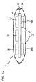
図1Aは、本発明の一実施形態による感知装置1を示す。感知装置1は、概して、センサー組立体2、算出装置20、通信装置30、およびエネルギー貯蔵装置40を含む複数の構成要素を含み、これらの構成要素はそれぞれ、ボード80に取り付けられ、算出装置20と電子通信している。構成要素は、ハウジング90で囲まれている。センサー組立体2は、複数のエミッターを有するエミッターアレイ100と、複数の検出器を有する検出器アレイ200と、を含む。
FIG. 1A shows a sensing device 1 according to one embodiment of the present invention. The sensing device 1 generally includes a plurality of components including a
本発明による一実施形態では、感知装置1は、患者の生理学的状態を決定するように構成される。「患者」とは、生理学的状態が感知装置1により測定される人間または動物を意味する。本明細書に開示する発明は、医学的状況で説明されるが、本明細書に開示する教示は、経時的に測定を行うために小型のデータ取得組立体が望ましい、他の状況で等しく適用可能である。例えば、本発明によるセンサー組立体は、水没するかまたは到達が困難な適用(submersed or difficult to reach applications)、危険な環境、重量およびサイズ制限を有する適用、実地調査活動などで、望ましい場合がある。 In one embodiment according to the invention, the sensing device 1 is configured to determine the physiological state of the patient. “Patient” means a human or animal whose physiological state is measured by the sensing device 1. Although the invention disclosed herein is described in a medical context, the teachings disclosed herein are equally applicable in other situations where a small data acquisition assembly is desirable for taking measurements over time. Is possible. For example, sensor assemblies according to the present invention may be desirable in submerged or difficult to reach applications, hazardous environments, applications with weight and size restrictions, fieldwork activities, etc. .
本発明による一実施形態では、感知装置1は、患者の身体において皮下に植え込まれる。しかしながら、感知装置1は、様々な植え込み技術を用いて異なる場所に植え込まれ得ることが理解されるべきである。例えば、感知装置1は、胸郭の下で胸腔内に植え込まれてよい。ハウジング90は、円形または楕円形のディスクの形状に形成されてよく、寸法は、25セント硬貨を2枚重ねたのとおおよそ同じである。当然のことながら、ハウジング90は、適用に応じて、様々な他の形状で構成されてよい。ハウジングは、患者の身体内部で皮下に組立体を固定するために、縫合糸を受容するよう、図1Bおよび図1Cに示す、外側に突出する4つのループ92を含むことができる。ハウジング90の形状に応じて、より多いかまたはより少ないループ92が設けられてよい。そのように固定されると、センサー組立体2は内側を向いて位置付けられ、一方、以下で詳細に説明するエネルギーカプラーは、外側を向く。
In one embodiment according to the present invention, the sensing device 1 is implanted subcutaneously in the patient's body. However, it should be understood that the sensing device 1 can be implanted at different locations using various implantation techniques. For example, the sensing device 1 may be implanted in the thoracic cavity under the thorax. The
別の実施形態では、感知装置1は、患者の身体の外側に位置付けられる。支持部材が、身体の外側で感知装置1を支持するために設けられる。支持部材は、永続的または一時的に感知装置1に連結されることができる。一実施形態では、支持部材は、支持部材を患者の身体に接着連結する接着層を含む。別の実施形態では、支持部材は、患者の身体に対して感知装置1を保持するための、弾性であってよいベルトを含む。 In another embodiment, the sensing device 1 is positioned outside the patient's body. A support member is provided for supporting the sensing device 1 outside the body. The support member can be permanently or temporarily connected to the sensing device 1. In one embodiment, the support member includes an adhesive layer that adhesively connects the support member to the patient's body. In another embodiment, the support member includes a belt that may be elastic to hold the sensing device 1 against the patient's body.
感知装置1は、超音波機器などの外部マッピングシステムの助けを借りて、皮下に植え込まれるか、または患者の上に位置付けられることができる。適切に設置することで、目的の血管が、感知装置1の感知範囲内に確実に位置する。目的の血管が大動脈である場合、感知装置1は、患者の胸部または背中の上で、本明細書に記載する方法で取得される測定値の、肋骨による干渉を減少させる場所に、位置付けられてよい。 The sensing device 1 can be implanted subcutaneously or positioned on a patient with the aid of an external mapping system such as an ultrasound device. By appropriately installing, the target blood vessel is surely positioned within the sensing range of the sensing device 1. If the blood vessel of interest is the aorta, the sensing device 1 is positioned on the patient's chest or back at a location that reduces the interference caused by the ribs of the measurements obtained by the methods described herein. Good.
本発明による一実施形態では、感知装置1は、他の装置に接続し、かつ他の装置と情報交換するための通信ポートを有する。コネクタ85が図示される。ボード80を通じて感知装置1の他の構成要素に接続されるコネクタ85の働きは、図6Aおよび図6Bを参照して、以下でさらに詳細に説明する。
In one embodiment according to the present invention, the sensing device 1 has a communication port for connecting to and exchanging information with other devices. A
1.血管検出器
本発明による一実施形態では、感知装置1は、静脈または動脈などの血管中で運ばれる患者の血液のパラメータを感知する。例示的な実施形態では、感知装置1は、電磁スペクトルの赤外(IR)領域で電磁エネルギーのビームを放射し、血管中を循環する血液から反射されたIR信号を検出する。しかしながら、本発明の教示に一致する他のタイプの電磁エネルギーが利用され得ることが理解されるべきである。感知装置1は、患者の身体による最小限の干渉または吸収でその身体を通過する能力と、所望の血液パラメータ値を伝達する能力に合わせて選択された特定の血液成分から反射する能力と、に合わせて選択された1つまたは複数の周波数でIRビームを放射することができる。例示的な実施形態では、感知装置1は、赤血球中の、鉄を含有し酸素を運ぶ金属タンパク質である、ヘモグロビンから反射するように選択された、赤外線ビームを放射する。
1. Blood vessel detector In one embodiment according to the present invention, the sensing device 1 senses parameters of a patient's blood carried in a blood vessel such as a vein or artery. In an exemplary embodiment, sensing device 1 emits a beam of electromagnetic energy in the infrared (IR) region of the electromagnetic spectrum and detects an IR signal reflected from blood circulating in the blood vessel. However, it should be understood that other types of electromagnetic energy consistent with the teachings of the present invention may be utilized. The sensing device 1 has the ability to pass through the body with minimal interference or absorption by the patient's body and to reflect from a particular blood component selected for the ability to transmit a desired blood parameter value. The IR beam can be emitted at one or more frequencies selected together. In an exemplary embodiment, sensing device 1 emits an infrared beam selected to reflect from hemoglobin, a metallic protein that contains iron and carries oxygen in red blood cells.
光セルアレイを用いて、IRビームを放射および検出することができる。以下に詳細に開示するように、各アレイは、4つのセルをそれぞれ備える4つの列の格子状に配列された16個の光セルを有するものとして表示される。以下に記載する特定の操作条件下で、エミッターアレイ100の光セルは全て、同時にビームを放射するが、他の操作条件下では、各光セルは、選択された時間にビームを放射して、特定の情報を入手し、かつ/またはエネルギーを節約する。さらに別の実施形態では、光セルは、エミッターおよび検出器が、エミッターおよび検出器の互い違いの横列もしくは縦列をなして(in alternating rows or columns)、間隔を置いて配置され、かつ/または分散される配列を含む、あらゆる方法で、感知装置の表面上に分散される。
An optical cell array can be used to emit and detect IR beams. As disclosed in detail below, each array is displayed as having 16 light cells arranged in a grid of 4 columns, each with 4 cells. Under certain operating conditions described below, all of the light cells of the
図2は、赤血球5中にヘモグロビンを有する血液4を運ぶ血管3と、一対の光セル、エミッター101および検出器201、すなわちセンサー組立体2、との間の関係を示す。センサー組立体2は、Motorolaにより製造された8572系の光センサーから選択されてよい。エミッター101は、光子101’を含む光子のビームを放射する。図3を参照して以下でさらに詳細に説明するように、ビーム中の光子の一部は、血管3を通過し、一部は、この例では光子101’を含む、反射ビームとして反射される。受信機201が反射ビームを受け取る。算出装置20は、ビームを放射するようにエミッター101を向け、セル201が反射ビームを検出するのに必要な時間を測定する。ビームは、既知の一定の速度で組織の中を移動する。矢印9で示す、中心線8上の光セル101と光セル201との間の中間点から血管3までの距離は、放射と検出との間の移動時間、および光セル101と光セル201との間の幾何学的関係から計算され得る。
FIG. 2 shows the relationship between a
一実施形態では、エミッター101により放射されるビームを少なくとも部分的に焦点に集める(focus)ために1つまたは複数のレンズが含まれてよく、ビームの断面寸法は、ビームの移動距離にわたり、ビームの元の寸法のほんのわずかな割合以内で、一定のままである。各エミッターにより生成されるビームを焦点に集めるために、コリメーターが含まれてよい。次にエミッタービームは、検出器により生成される信号と相互に関連付けられ、血管に関する追加情報を提供することができる。
In one embodiment, one or more lenses may be included to at least partially focus the beam emitted by the
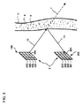
図3および図4は、エミッターアレイ100および検出器アレイ200それぞれに位置付けられた送信機および受信機を含む、センサー組立体2の一実施形態を示す。エミッターアレイ100は、マトリックス状に配された16個のエミッター101〜116を含み、算出装置20により方向付けられる16本のビームを放射することができる。単純にするために、図3では、エミッター104からの放射ビーム10のみが図示される。ビーム10の一部が、反射ビーム11として血管3から反射される。数字7は、ヘモグロビンにより反射されなかった、ビーム10の一部を表す。検出器アレイ200は、マトリックス状に配された16個の検出器201〜216を含む。検出器アレイ200は、反射ビーム11中の光子を受け取る。さらに具体的には、この例では、検出器204が、反射ビーム11中の光子を受け取る。
3 and 4 illustrate one embodiment of a
それぞれ4個のセルからなる4つの横列を含む例示的な正方形のマトリックスが図示されるが、セルのサイズ、所望の測定精度、およびセンサー組立体2と標的血管との間の距離に応じて、より多いかまたはより少ないセルが、センサー組立体2に配されてもよい。その意図する目的に適した反射ビームを提供するため、十分な光子が放射されなければならない。別の実施形態では、各アレイは、25個のセルを含む。さらに別の実施形態では、各アレイは、12個のセルを含む。エミッターおよび検出器アレイ中のセルの数、ならびに各セルのサイズを等しくする必要はない。追加の検出器を検出器アレイに加えて、さらに以下に説明するように、血管のマッピングの解像度を増大させることができる。一実施形態では、検出器アレイ200における検出器は、正方形であり、各辺の長さは、1mmである。別の実施形態では、各辺は、2.5mmである。放射ビームの幅は、距離と共にわずかに広くすることができる。例えば、2.5mmのビームは、そのビームが10cmの距離に位置する血管に当たるときに約3.5mmまで広くされてよい。
An exemplary square matrix comprising four rows of four cells each is illustrated, depending on the cell size, the desired measurement accuracy, and the distance between the
図4は、図3に示されたセンサー組立体2の概略的表示の側面図を示す。エミッターアレイ100の各エミッターが、検出器アレイ200の対応する検出器と対にされることが理解されるべきである。さらに具体的には、エミッター101は検出器201と対にされ、エミッター105は検出器205と対にされ、エミッター109は検出器209と対にされ、エミッター113は検出器213と対にされる。残りのエミッターおよび検出器(不図示)は、同様に対にされる。本発明の一実施形態では、エミッターと、その対を成す検出器との間の角度は、各対について同じである。図示のように、放射ビーム113Eは、血管3の方に向けられ、そのビームが血管3に当たると、反射ビーム113Rが検出器213により受け取られる。各センサー組立体2について、放射ビーム113Eおよび反射ビーム113Rにより形成される角度は、その他のエミッターセル/検出器セル対の放射ビームおよび反射ビームにより形成される角度と同じである。この角度は、本明細書では共通角と呼ぶ。
FIG. 4 shows a side view of a schematic representation of the
しかしながら、それぞれのエミッターおよび検出器対の間で異なる共通角を有する、様々な異なるセンサー組立体2を構築し得ることが理解されるべきである。例えば、図4のエミッターアレイ100のセルと、検出器アレイ200の対をなすセルとの間の共通角は、45°であってよい。患者の身体内にさらに入り込むように構成された別のセンサー組立体2では、それらの対間の共通角は、30°であってよい。患者の解剖学的構造が、使用するのに適切なセンサー組立体2を決定し得る。例えば、感知装置1が、非常にやせた患者または非常に小柄な患者において皮下に植え込まれる場合、センサー組立体2と目的の血管3との間の距離は、非常に太った患者または非常に大柄な患者における対応する距離に比べて、小さくなり得る。したがって、エミッターと、対をなす検出器との間により大きな共通角を有するセンサー組立体2が、やせた患者に適切であり、一方、より小さな共通角を有するセンサー組立体2が、太った患者に適切であろう。
However, it should be understood that a variety of
いくつかの実施形態では、エミッターアレイ100および検出器アレイ200は、互いに対して角度をなして、感知装置1に取り付けられてよいことがさらに理解されるべきである。図4では、エミッターアレイ100および検出器アレイ200は、共面である(すなわち、互いに対してゼロの角度にある)。エミッターアレイ100および検出器アレイ200に関するサイズの制約または所望の取り付け場所の結果、これらのアレイは、この図面に点線で示すように、互いに向かって傾斜されてよい。
It should be further understood that in some embodiments,
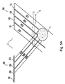
図5A〜図5Cは、図4に示すセンサー組立体2の概略的表示であり、血管3に対して垂直に方向付けられた小血管12が追加されている。図5Aでは、エミッターアレイ100および検出器アレイ200の外縁に沿ったセルのみが図示されている。各エミッターセル101、105、109、113は、IRビーム101E、105E、109E、113Eをそれぞれ放射する。血管12は、図面中さらに遠くにあり、また放射ビーム101E、105E、109E、113Eのいずれも血管12に当たらないので、透視図で示されている。図示のとおり、放射ビーム101Eは、血管3および12に完全に達し損なう。したがって、検出器201によって検出される反射ビームはない。放射ビーム105Eの一部が血管3に当たる。血管3に当たる光子の一部が、反射ビーム105Rとして検出器205において反射および検出される。放射ビーム109Eは全て、血管3に当たる。血管3中のヘモグロビンにより反射される放射ビーム109Eの光子の部分は、反射ビーム109Rとして検出器209において検出される。放射ビーム101Eと同様に、放射ビーム113Eの一部のみが、血管3に当たり、検出器213において反射ビーム113Rをもたらす。
5A-5C are schematic representations of the
図5Aに比べ、図5Bは、第2の縦列のエミッター102、106、110、114および第2の縦列の検出器202、206、210、214を通る平面の、本質的にページ内にさらに遠くまで入り込む図(view farther into the page)である。この図では、血管12は、エミッター102、106、110および114から放射されるビームにより照らされるエリアに位置するので、実線で図示されている。作動されると、エミッター102は、放射ビーム102Eを放射し、放射ビーム102Eは、完全に血管3に届き損なう。しかしながら、放射ビーム102Eの一部が、血管12に当たり、当たる光子の一部が、反射ビーム102R’として反射される。この例では、反射ビーム102R’のいずれも、血管12の場所のために、検出器202により検出されない。図5Aの放射ビーム105Eと同様に、放射ビーム106Eの一部が血管3に当たる。しかしながら、ここでは、放射ビーム106Eの別の部分が、血管3に到達する前に血管12に当たる。血管12に当たる光子のうちいくつかは、反射ビーム106R’として反射され、反射ビーム106’は、検出器206により検出されない。したがって、血管3に当たる放射ビーム106Eの部分は、血管12の干渉のため、血管3に当たった放射ビーム105Eの部分よりも小さい。したがって、検出器206において検出される反射ビーム106Rは、検出器205において検出される反射ビーム105Rより低い強度を有する。同様に、血管12の干渉は、反射ビーム110R’および反射ビーム114R’を結果として生じ、これらにより、検出器210および214それぞれで検出される反射ビーム110Rおよび114Rにおける光子の数が減少する。
Compared to FIG. 5A, FIG. 5B shows that the plane through the second column of emitters 102, 106, 110, 114 and the second column of
図5Cは、第3の縦列のエミッター103、107、111、115および第3の縦列の検出器203、207、211、213を通る平面の、本質的にページ内にさらに遠くに入り込む図である。図5Cでは、血管12は、放射ビーム103E、107E、111E、115Eにより照らされるエリアを占めていないので、再び透視図で示されている。血管12が放射ビームに干渉せず、血管3の場所が図5Aに図示されるものと同じであるので、放射ビーム103E、107E、111E、115Eの移動経路、および結果として生じる反射ビーム107R、111R、115Rの特性は、図5Aに関して説明した対応するビームと同じである。
FIG. 5C shows a plane that passes through the
本発明の一実施形態によると、算出装置20は、検出器アレイ200から受信した信号をフィルタリング、スケーリング、および調節することによって、それらの信号を処理し、検出器アレイ200により受信されたビームの強度すなわち動力に対応する測定値を計算する。一実施形態では、算出装置20は、検出器アレイ200により生成されたアナログ信号をデジタル化する。以下の表1および表2では、1の値は、全動力の100%を示す。言い換えれば、1の値は、対応するエミッターセルが目的の血管3の最大干渉(したがって血管3による反射)に遭遇する波を発する場合に検出器セルにより受け取られると予測される動力に等しい。代替的な実施形態では、電子回路(不図示)を使用して、検出器アレイ200から受信される信号をフィルタリング、スケーリング、および調節し、電子回路の出力が、処理のため算出装置20に与えられる。別の工程では、算出装置20は、以下でさらに説明するように、測定値を評価およびマッピングして、血管3の場所および直径を決定する。
According to one embodiment of the present invention, the
本発明による一実施形態では、0.7cmの幅を有する血管部分に等しくなるように、全動力信号(full power signal)をスケーリングする。全動力の各断片は、0.7cm幅の断片を直線的に表す。血管の幅すなわち直径は、場合によっては、検出器セルの横列または縦列における測定値を加えることにより計算される。血管の直径は、縦列の値を加えたときの2つまたは3つ以上の横列または縦列における測定値が、10%未満だけ異なる場合に、識別される。別の実施形態では、血管の直径は、2つまたは3つ以上の横列または縦列における測定値が、5%未満だけ異なる場合に、識別される。 In one embodiment according to the invention, the full power signal is scaled to be equal to a vessel portion having a width of 0.7 cm. Each piece of total power represents a 0.7 cm wide piece linearly. The width or diameter of the vessel is optionally calculated by adding measurements in the detector cell row or column. A vessel diameter is identified if the measured values in two or more rows or columns when adding column values differ by less than 10%. In another embodiment, the vessel diameter is identified if the measurements in two or more rows or columns differ by less than 5%.
表1は、図4に示す血管3の描写に対応する測定値の概念的表示を示す。これらの値は、エミッター101〜104から放射されたビーム中の光子はいずれも、アレイ200の、対をなす検出器201〜204によって反射されず、かつその後検出されなかったことを示す。第2の横列(検出器205〜208)および第4の横列(検出器213〜216)のセルによりさらに多くの光子が検出され、第3の横列(検出器209〜212)のセルにより、いっそう多くの光子が検出された。表1から明らかであるが、検出器の各縦列で検出された信号は同じである。全動力信号が0.7cmに等しい、前記に開示した実施形態によると、血管3の幅すなわち直径は、縦列の各検出器の信号に0.7cmを掛け合わせ、結果として生じる積を足すことにより、算出されることができる。さらに具体的には、この例の血管3の直径は、0.0*0.7+0.8*0.7+1.0*0.7+0.8*0.7、すなわち1.82cmである。

表2は、図1と同様であるが、図5A〜図5Cに示す血管3および12の描写に対応する、処理値の概念表示を示す。検出器206、210および214に対応する縦列2の減少した値は、図5Bに示すように血管12により生じる干渉を表す。縦列1、3および4の値は、5%未満だけ異なる(実際には、図示のとおりそれらは同一である)。したがって、算出装置20は、縦列2の信号を無視し、前述したように、縦列1、3または4のいずれかの信号を用いて血管2の直径を算出することができる。
本発明による一実施形態では、所定のサイズより小さい直径を有する血管の存在を示す測定値は、削除されるか、または除去されて、目的の血管の、より明確な表示を得る。一実施形態では、1cm未満の血管直径に対応する測定値は、削除される。そのような実施形態では、目的の血管は、感知装置1の取り付け場所付近のほぼあらゆる他の血管よりも実質的に大きい、既知のおおよその直径(患者の身体特性による)を有する、大動脈である。 In one embodiment according to the present invention, measurements indicative of the presence of blood vessels having a diameter smaller than a predetermined size are deleted or removed to obtain a clearer indication of the target blood vessel. In one embodiment, measurements corresponding to vessel diameters less than 1 cm are deleted. In such embodiments, the vessel of interest is an aorta having a known approximate diameter (depending on the patient's physical characteristics) that is substantially larger than almost any other vessel near the attachment location of the sensing device 1. .
前述したように血管の直径を決定し、その場所をマッピングする際に、各エミッター101〜116は、立て続けに個々に作動されることが理解されるべきである。様々な図面でいくつかの放射ビームが同時に図示されているが、1回にただ1つのビームが放射されて、ビームの重ね合わせを避け、そのような重ね合わせにより混同されない信号を生成する。1つのビームを放射し、対をなす検出器において1つの反射ビームを受け取ることにより、各信号は、血管に関する、混同されない情報(un-confounded information)を与える。各信号は、単一のビームが経験する干渉および拡散を表す。本発明の一実施形態では、ビームは、エミッター101から始めて、横列ごとにスキャンする形で個々に放射され、これは、エミッター116が作動されるまで連続的に追随された(followed)。他の実施形態では、他のシーケンスが追随された。
It should be understood that in determining the vessel diameter and mapping its location as described above, each emitter 101-116 is actuated individually in a row. Although several radiation beams are shown simultaneously in the various drawings, only one beam is emitted at a time, avoiding beam superposition and generating signals that are not confused by such superposition. By emitting one beam and receiving one reflected beam at a pair of detectors, each signal provides un-confounded information about the blood vessel. Each signal represents the interference and spread experienced by a single beam. In one embodiment of the invention, the beams were emitted individually starting from
アレイの検出器がスキャンされると、各検出器により生じた信号は、各ビームが経験する干渉および拡散を表す。概して、スキャンは、血管の場所および直径のマッピングについて情報を与える。血管内の血液が十分に酸素添加されている場合、血液は、より多くの鉄を含有し、検出器は、全動力(full power)を表す信号を生成する。血液が十分に酸素添加されていない場合、検出器は、全動力未満を示す信号を生成する。しかしながら、スキャンは迅速に行われるので、酸素添加レベルは、各スキャンサイクル中、一定であり、したがって、各検出器により受け取られるビームの動力差は、酸素添加レベルに関係なく、血管の位置および直径をマッピングするのに使用されることができる。 As the array detectors are scanned, the signal produced by each detector represents the interference and spread experienced by each beam. In general, a scan provides information about the location and diameter mapping of a blood vessel. If the blood in the blood vessel is sufficiently oxygenated, the blood will contain more iron and the detector will generate a signal that represents full power. If the blood is not fully oxygenated, the detector generates a signal indicating less than total power. However, since the scan is performed quickly, the oxygenation level is constant during each scan cycle, and therefore the beam power difference received by each detector is independent of the oxygenation level, regardless of the oxygenation level. Can be used to map.
大動脈付近にある肺動脈の直径は、大動脈の直径と同様である。したがって、大動脈の直径を識別および測定するためには、感知装置1は、肺動脈と大動脈とを見分けなければならない。これは、肺動脈および大動脈双方が所定の直径閾値を超える直径を有するためである。感知装置1は、それぞれの酸素飽和度を測定し、最も高い酸素飽和度を有する血管(肺動脈は脱酸素化血液を心臓(heat)から肺へ運ぶので、これは常に大動脈である)を選択することによって、2つの血管を見分ける。 The diameter of the pulmonary artery in the vicinity of the aorta is similar to the diameter of the aorta. Therefore, in order to identify and measure the diameter of the aorta, the sensing device 1 must distinguish between the pulmonary artery and the aorta. This is because both the pulmonary artery and the aorta have a diameter that exceeds a predetermined diameter threshold. The sensing device 1 measures each oxygen saturation and selects the blood vessel with the highest oxygen saturation (this is always the aorta because the pulmonary artery carries deoxygenated blood from the heart to the lung) Differentiate the two blood vessels.
酸素飽和度を測定する際、感知装置1は、エミッターアレイ100の全エミッター101〜116を同時に作動させる。まず、感知装置1は、既に述べたスキャン法によって、大動脈などの目的の血管の位置および直径を算出する。血管の寸法、エミッターアレイおよび検出器アレイと血管との間の幾何学的関係、ならびにエミッターアレイおよび検出器アレイの物理的特性、例えば、アレイのサイズ、エミッタービームの幅、エミッターおよび送信機の配置、に基づいて、感知装置1は、既知の光子拡散等式に従って、潜在的な最大酸素飽和度値を算出する。各患者の生理学的特性は異なるので、感知装置1は、算出装置20のメモリに記憶された基準値を用いて、各患者について、潜在的な最大値を較正することができる。感知装置1はその後、エミッターアレイからビームを同時に放射し、検出器アレイにおいて反射ビームを検出し、反射ビームを動力信号に変換する。一実施形態では、感知装置1は、血管により反射された光子を受け取る検出器から生成される信号をまとめ、総計値を潜在的な最大値で割って、飽和比率を得る。飽和比率は、血管を通って流れる血液中の飽和度を表す。別の実施形態では、感知装置1は、血管に当たるであろうビームを生成すると予測されるエミッターを作動させるにすぎず、ビームが血管に当たらないであろうエミッターは作動させずに、エネルギーを節約する。別の実施形態では、感知装置1は、その血管に当たり、他の血管には当たらないであろうビームを生成すると予測されるエミッターを作動させるのみで、エネルギーを節約し、光子拡散計算を単純化する。さらなる実施形態では、感知装置1は、エミッターおよび検出器の対を選択的に作動させて、作動する対の数を最小限にし、動力を節約することができる。
When measuring oxygen saturation, the sensing device 1 operates all the
通常の操作条件下で、感知装置1は、酸素飽和度測定を1日当たり1回または2回行うことができる。異常な状態が検出された場合、または、以下に説明するような鼓動検出器として機能する場合、感知装置1は、短い期間中に、複数回の酸素飽和度測定を行うことができる。非常に頻繁に測定を行う場合はかなりの電力が消費されるが、取得されるデータは、患者の健康にとって重要である場合がある。 Under normal operating conditions, the sensing device 1 can perform oxygen saturation measurements once or twice per day. When an abnormal state is detected, or when functioning as a heartbeat detector as described below, the sensing device 1 can perform a plurality of oxygen saturation measurements during a short period. While taking very frequent measurements consumes considerable power, the data acquired can be important to the patient's health.
一実施形態では、感知装置1は、心臓の鼓動も計算する。先に論じたように、検出器は、血液中の鉄含有量を表す動力信号(power signals)を生成する。心臓は、大動脈を通じて酸素添加された血液を送り出すので、動力信号は変動する。複数の動力信号を立て続けに入手して、動力測定変動をとらえることができる。さらに具体的には、ある期間にわたり(例えば15秒)多数の酸素飽和度測定(例えば1秒当たり10回)を行うことによって、飽和度測定は、心臓の鼓動を表すパターンまたは周期性を示す。算出装置20は、飽和度測定値に合う曲線、例えば正弦曲線、を定めることができ、この曲線は、心臓周期に直接対応している。算出装置20は、曲線のピーク値の周波数を決定して、その期間を決定することができる。各期間は心臓周期を表す。サンプル期間(例えば、15秒)における心臓周期の数に、適切な因子を掛け合わせることにより、算出装置20は、1分当たりの心臓周期に関して、脈拍数を決定することができる。一実施形態では、算出装置20は、正常な基準値として心臓の鼓動値を記憶し、心臓の鼓動値を基準値と比較することにより、異常または不規則な心律動を検出する。
In one embodiment, the sensing device 1 also calculates the heartbeat. As discussed above, the detector generates power signals that represent iron content in the blood. As the heart pumps oxygenated blood through the aorta, the power signal fluctuates. Multiple power signals can be obtained in quick succession to capture power measurement variations. More specifically, by performing a number of oxygen saturation measurements (eg, 10 times per second) over a period of time (eg, 15 seconds), the saturation measurement exhibits a pattern or periodicity that represents the heartbeat. The
本発明による感知装置1の別の実施形態では、センサー組立体2、および感知装置1の他の特徴部は、ペースメーカー、心臓再同期療法(CRT)装置、植え込み型除細動器(ICD)などといった、植え込み型心臓装置と統合される。
In another embodiment of the sensing device 1 according to the present invention, the
2.算出装置
算出装置20は、複数の構成要素を含む。構成要素は、独立した構成要素であるかのように本明細書で説明されるが、これらの構成要素は、特定用途向け集積回路などの単一の装置に組み合わせられてよい。算出装置20は、プロセッサ、メモリ、プログラム、入力および出力を含む。メモリは、RAM、ROM、EEPROM、フラッシュメモリまたは他のメモリテクノロジーを含んでよいが、これらに限定されない。プロセッサおよびメモリは、集積回路の中に構築されてよい。集積回路は、エミッターアレイ100、検出器アレイ200、および通信装置30を含むことができる。さらに、算出装置20は、集積回路上にA/Dおよび/またはD/A変換器を含んでよい。代わりに、A/Dおよび/またはD/A変換器が別個に設けられてもよい。
2. Calculation device The
プログラムは、データに応答してタスクを実行するようプロセッサに指示する、コンピュータ命令を表す。プログラムは、メモリ中に存在する。基準データおよび測定データを含むデータもメモリ中に存在する。基準データは、外部入力に応答して、または経時的に収集された測定データの特性に応答して、ROMに記憶されてよく、または経時的に変更され得るようRAMに記憶されてもよい。測定値に応答するプロトコルも設けられてよい。プロトコルは、持続性メモリに記憶されてよく、または、RAMなど非持続性メモリに記憶されてもよい。 A program represents computer instructions that instruct a processor to perform a task in response to data. The program exists in memory. Data including reference data and measurement data is also present in the memory. The reference data may be stored in ROM in response to external input or in response to characteristics of measurement data collected over time, or may be stored in RAM so that it can be changed over time. A protocol that responds to the measurement may also be provided. The protocol may be stored in persistent memory or may be stored in non-persistent memory such as RAM.
算出装置20は、入力および出力を通じてセンサー組立体2および通信装置30を制御する。算出装置20は、エミッター101〜116により放射された複数のビームの数、周波数、動力レベル、および放射順序(emission sequence)を制御して、最小量のエネルギーを用いて所望の測定値を得ることができる。
The
図6Aは、感知装置1と情報を交換するシステム300を開示する。システム300は、通信装置30を有する感知装置1と、オプションとしてコネクタ85と、を含む。システム300は、コンピュータ302、ケーブル303によりコンピュータ302に動作可能に連結されたドッキングステーション304、電話306も含んでよい。本発明の一実施形態では、システム300は、算出装置20により実行される処理に基づいて、感知装置1に/感知装置1から、無線で通信信号312を送受信する。
FIG. 6A discloses a
コネクタ85は、ドッキングステーション304に差し込まれるように構成される。ドッキングステーション304上にドッキングされた感知装置1が図示される。ドッキングされている間、感知装置1は、エネルギー貯蔵装置40を充電することができる。ドッキングステーションは、コンピュータ302に動作可能に連結されて、患者の上または中に感知装置1を置く前に算出装置20のメモリに記憶されたプログラムおよび基準値を更新する。別の実施形態では、感知装置2は、患者の外部に位置付けられ、コネクタ85は、エネルギー源に操作上連結されて、感知装置2に動力を与え、エネルギー貯蔵装置40の消耗を防ぐ。
本発明によるさらなる実施形態では、追加のセンサーおよび装置が、コネクタ85を通じて感知装置1に連結されることができる。他のセンサーおよび装置は、追加のセンサー組立体2、温度センサー、圧力センサー、および加速度計を含んでよいが、これらに限定されない。その他の装置は、算出装置を含んでも含まなくてもよい。他の装置はまた、ハウジング90内で感知装置1と組み合わせられてよい。統合感知装置が、名称を「INTEGRATED HEART MONITORING DEVICE AND METHOD OF USING SAME」とする、前記に参照した関連の米国実用新案出願に開示されている。感知装置1の働きは、追加のセンサーおよび装置を操作するように構成された修正プログラムを、算出装置20のメモリにダウンロードすることによって、追加のセンサーおよび装置を操作するように構成されてよい。ダウンロードは、算出装置20がドッキングステーションにドッキングされている間に行われてよい。あるいは、新しいプログラムが、算出装置40を通じて無線でダウンロードされてもよい。
In a further embodiment according to the present invention, additional sensors and devices can be coupled to the sensing device 1 through the
図7は、本発明の一実施形態による算出装置20によって実行されるプログラムの1つのルーチンを示すフローチャートである。工程400で、算出装置20がセンサー組立体2を作動させ、前述したように実行されている測定に応じて、全エミッター101〜116がビームを放射するか、またはエミッターが連続的に個々のビームを放射する。工程400は、反射ビームを表す、検出器201〜216における信号を生成する手順も表す。
FIG. 7 is a flowchart showing one routine of a program executed by the
工程402で、算出装置20は、信号を処理して測定値を得る。処理には、固有の信号ノイズを除去すること、信号をアナログ形態からデジタル形態に、光学形態からデジタル形態に(optical to digital form)変換すること、検出した信号をスケーリングし、また別様に調節することを含んでよい。代わりに、いくつかの処理機能を、A/D変換器などの回路によって行ってもよい。処理後、測定値は、メモリに記憶されてよく、またはその値を記憶させるべきかどうか決定するために分析されてよい。工程400および402は、前記の開示に従って所望のパラメータを計算するため十分な測定値を得るように、必要に応じて繰り返されてよい。工程400および402は、同時に行われてよい。
In
工程404で、算出装置20は測定値を分析する。分析は、パラメータデータの計算、および/または診断を含み得る。パラメータデータは、血管の直径および場所、酸素飽和度、心律動などといった計算値を指す。診断は、患者の異常な状態を検出するため、パラメータ値を基準値と比較することを指す。基準データは、患者の正常な状態に対応する。異常な状態が検出された場合、算出装置20は、測定値が収集されたときにそれらを通信する(不要な動力を消費する)か、または、メモリがいっぱいになるかもしくは所定の送信時間に達するまで測定値を送信するのを待つ(患者を待機期間中に不要な危険に曝す)のではなく、警報を伝達することができる。
In
基準値は、標的の値、および許容可能な変動範囲もしくは限界を含むことができる。パラメータ値は、それらが標的の基準値または範囲外である場合に、異常を示すことができる。いくつかの実施形態では、パラメータ値は、例えば移動平均などの統計値を生成でき、パラメータの統計値が、予測量を超えて、基準の統計値と異なる場合に、異常が検出される。 The reference value can include a target value and an acceptable variation range or limit. Parameter values can indicate an anomaly if they are outside the target reference value or range. In some embodiments, the parameter value can generate a statistical value, such as a moving average, for example, and an anomaly is detected when the statistical value of the parameter exceeds the predicted amount and differs from the baseline statistical value.
パラメータデータが、所定量を超えて、予測値と異なる場合、算出装置20は、新しい測定サイクルを開始し、異常を診断する前にパラメータデータを確認することができる。一実施形態では、算出装置20は、測定値が予測値と10%超異なる場合に、大動脈の場所および直径を再びマッピングする。別の実施形態では、算出装置20は、測定値が予測値と5%超異なる場合に、大動脈の位置および直径を再びマッピングする。
If the parameter data exceeds the predetermined amount and is different from the predicted value, the
1つの異常な医学的状態は、低酸素飽和度である。算出装置20は、例えば酸素飽和度値が低すぎるかどうかを決定するために、測定値の分析を実行するよう構成されていてよい。「正常な」酸素飽和度の値は、患者ごとに様々であり、患者の状態次第であるが、概して、90%未満の酸素飽和度測定値は、低いとみなされる。別の異常な医学的状態は、前述した方法で検出され得る不規則な心律動である。
One abnormal medical condition is hypoxia saturation. The
さらなる異常な医学的状態は、外部で、または追加のセンサーから得られた値を使用して検出されることができる。感知装置1に含まれ得る追加のセンサーは、名称を「DOPPLER MOTION SENSOR APPARATUS AND METHOD OF USING SAME」および「INTEGRATED HEART MONITORING DEVICE AND METHOD OF USING SAME」とする、前記に参照した、関連の米国実用新案出願に開示される。 Further abnormal medical conditions can be detected externally or using values obtained from additional sensors. Additional sensors that can be included in the sensing device 1 are related US utility models referred to above, named “DOPPLER MOTION SENSOR APPARATUS AND METHOD OF USING SAME” and “INTEGRATED HEART MONITORING DEVICE AND METHOD OF USING SAME”. Disclosed in the application.
感知装置1がドップラーセンサーを含む実施形態では、血管の直径および場所は、流体の速度およびポンプ速度(pumping rate)を計算するのに使用されてよい。血管が大動脈である場合、これらのパラメータは、心臓出力に関係する異常な状態を計算および診断するのに使用されてよい。大動脈パラメータは、ドップラーセンサーで得られた収縮期および拡張期の血液速度値と組み合わせられて、収縮期および拡張期の血圧を計算することができる。他のセンサーは、ECGセンサーおよび温度センサーを含み得る。 In embodiments where the sensing device 1 includes a Doppler sensor, the vessel diameter and location may be used to calculate fluid velocity and pumping rate. If the blood vessel is an aorta, these parameters may be used to calculate and diagnose abnormal conditions related to cardiac output. Aortic parameters can be combined with systolic and diastolic blood velocity values obtained with a Doppler sensor to calculate systolic and diastolic blood pressure. Other sensors can include ECG sensors and temperature sensors.
工程406で、算出装置20は、異常な状態、特に、定められたプロトコルに従って重篤または危険な状態と判断される状態、が検出されると、警報を送信する。警報は、警報装置を始動させるか、または治療行為を行うよう患者に警告するために使用されることができる。治療行為は、身体活動を終了させるか、または低減させる場合がある。警報は、全地球測位(GPS)情報を救急施設(emergency service)に与えることもできる。図6Aを参照すると、異常な状態は、存在することが発見されると、コンピュータ302に表示され、かつ/または、通信装置30(例えば、NokiaモデムKNL 1147-V)によって介護者に送信されることもできる。警報は、状態に対応するテキストメッセージまたはコードを含むことができる。算出装置20はまた、異常な状態の検出に応答して連続的に、新しい測定サイクルおよび測定を開始することもできる。
In
工程408で、算出装置20は、治療を開始することができる。感知装置1は、通信装置30を通じて、警報に応じて治療を実行せよという外部コマンドを受信することができる。オプションとして、プロトコルに基づいて、異常な状態は、治療を施すように構成された装置に、そのような治療を実行する(deliver)よう指示するために、用いられてもよい。治療には、例えば電気ショックまたは薬剤送達が含まれ得る。
In
工程410で、パラメータ値または他の情報が、外部装置に伝達される。工程410は、前記工程のいずれとも同時に実行されてよい。パラメータ値は、メモリに記憶され、また通信装置30によって無線で送信されることができる。通信装置30からの通信信号は、異常な状態に応答して、外部で受信したコマンドに応答して、メモリの使用が所定量を超えるたびに、またはエネルギー貯蔵レベルが低いと判断されるたびに(後者の2つの状態は、メモリのオーバーフローの結果としてのデータロス、もしくはエネルギーロスを防ぐために確立された)、定期的に作動されることができる。感知装置1が通信装置30に加えて通信装置を含み得ることも理解されるべきである。例えば、通信装置30がセルラーモデムである場合、感知装置1は、バックアップブルートゥースまたはRF通信装置も含むことができる。このようなバックアップ装置は、セルラーモデムが(例えば、利用可能な動力が低い、セルラー信号または他の通信信号の受信が不良、ネットワーク範囲が不良などのため)情報を送信できない状況で、代替的な通信手段を提供するために望ましい場合がある。このような状況では、算出装置20は、バックアップ通信装置を作動させて、情報または警報を、代替的な外部受信装置に送信することができる。
In
工程410は、実質的にリアルタイムで介護者に最新情報を与えるように、例えばいったん異常な状態が検出されると実行されることができる。工程410は、1日に1回、1週間に1回、1ヶ月に1回などといった、規則的な間隔で行われてもよい。代わりに、またはこれらの送信に加えて、算出装置20は、要求されたデータ、または要求されたデータを表す情報を通信装置30に送信させることによって、(例えばヘルスケア提供者から)通信装置30により受信されたデータの要求に応答するよう、プログラムされることができる。
Step 410 can be performed, for example, once an abnormal condition is detected, so as to provide the caregiver with up-to-date information in substantially real time. Step 410 may be performed at regular intervals, such as once a day, once a week, once a month, or the like. Alternatively, or in addition to these transmissions, the
通信信号は、状態への注意を患者に喚起するように、患者の近くの設備により受信されるか、またはヘルスケア提供者、親族、もしくは他の所定のレシピエントによって、遠隔的に(例えばネットワークを介して)受信されることができる。 The communication signal may be received by equipment near the patient, to alert the patient to the condition, or remotely (e.g., networked by a healthcare provider, relative, or other predetermined recipient) Can be received).
3.通信装置
再び図6Bを参照すると、本発明の一実施形態による、通信信号を送受信するように構成されたシステムが示されている。通信装置30は、例えば携帯電話システムおよび/またはGPS衛星システムを介する、双方向通信装置である。通信装置30は、通信信号を送受信するアンテナ32を含む。数字312で識別される通信信号は、オプションの複数の外部通信装置のうち1つに、かつ、そこから、無線で移動する。
3. Communication Device Referring again to FIG. 6B, a system configured to send and receive communication signals according to one embodiment of the present invention is shown. The
外部通信装置は、コンピュータ302、または本明細書では携帯電話として具現化される、通信信号を無線で受信できる任意の電子装置、例えば電話306であってよい。電話306は、救急施設の配電盤、または病院もしくは医療センターの配電盤であってもよい。通信信号は、信号の情報をコード化するように設定または変更された、その特性のうち1つまたは複数を有する信号を意味する。限定ではなく一例として、通信信号は、音響媒体、RF媒体、赤外媒体、他の無線媒体、および前記のうちいずれかの組み合わせを含む。外部通信装置はまた、患者の身体の外側に位置する、例えば患者のベルトにクリップで留められた、リレーユニットであってもよい。リレーユニットは、通信装置30からの送信を受信する受信機、および、通信信号を別の外部通信装置に再送信する送信機を含むことができる。リレーユニットはまた、インターネットへ接続されるか、またはヘルスケア提供者のコンピュータに直接接続されるように、固定され、かつ配線で接続されていてもよい。同様に、リレーユニットは、ヘルスケア提供者から通信信号を受信し、その信号を通信装置30に送信することができる。
The external communication device may be a
通信装置30からの通信信号は、音声メッセージ、テキストメッセージ、および/または測定データを含むことができる。通信装置30により受信された通信は、更新された基準データなどのデータ、またはコマンドを含むことができる。コマンドは、例えば、患者に治療を施す、追加データを収集および送信する、または基準データを更新するなどのタスクを実行するための、算出装置20への命令を含むことができる。本発明による情報を通信する方法のさらなる実施形態は、名称を「METHOD AND SYSTEM FOR MONITORING A HEALTH CONDITION」とする、前記に参照した、関連の米国実用新案出願に開示されている。
The communication signal from the
4.エネルギー貯蔵装置
再び図1B、図1Cおよび図6を参照すると、エネルギー貯蔵装置40を再充電するシステムが、本発明による一実施形態で提供され得る。算出装置20は、エネルギー貯蔵装置40からエネルギーを受け取る。エネルギー貯蔵装置40は、バッテリなどのエネルギー貯蔵構成要素を含む。オプションとして、感知装置1はまた、エネルギー貯蔵装置40を充電するために外部供給源からエネルギーを受け取るエネルギーカプラーを含んでもよい。
4). Energy Storage Device Referring again to FIGS. 1B, 1C, and 6, a system for recharging the
エネルギーカプラーの一例は、外部の電磁信号310を受信し、そのような信号を電気エネルギーに変換してエネルギー貯蔵構成要素を再充電する、誘導コイル308などの電磁装置である。外部電磁装置308が、電磁信号310を生成し、この電磁信号は、エネルギー貯蔵装置40によって受信され、電気信号に変換される。エネルギー貯蔵装置40は、算出装置20に充電信号(charge signal)を提供することができる。算出装置20は、充電信号を基準充電信号と比較し、低充電通信信号(low charge communication signal)を開始し、患者および/またはヘルスケア提供者に警告することができる。代わりに、電圧センサーなどの検出器は、エネルギー貯蔵装置40の充電を監視し、充電が閾値より低くなると算出装置20に信号を与えるために使用されてよい。電磁装置308は、感知装置1の近くに置かれて、エネルギー貯蔵装置40を充電することができる。
An example of an energy coupler is an electromagnetic device, such as an
代わりに、またはさらに、エネルギーは、超音波振動の形で与えられてよい。例えば、圧電性トランスデューサーが感知装置1に含まれてよい。超音波振動が、外部から与えられてよい。トランスデューサーは、超音波振動により駆動されると電気を生成する。 Alternatively or additionally, energy may be provided in the form of ultrasonic vibrations. For example, a piezoelectric transducer may be included in the sensing device 1. Ultrasonic vibration may be applied from the outside. The transducer generates electricity when driven by ultrasonic vibration.
本発明は、例示的なデザインを有するものとして説明されてきたが、本発明は、本開示の趣旨および範囲内で、さらに改変されてよい。したがって、本出願は、本発明の全体的な原理を用いた、本発明のあらゆるバリエーション、使用法、または改造を含むことを意図している。さらに、本出願は、本発明が属する技術分野で既知のまたは習慣的な慣例に入る、本開示からの新発展(departures)を含むことを意図している。 While this invention has been described as having an exemplary design, the present invention may be further modified within the spirit and scope of this disclosure. This application is therefore intended to cover any variations, uses, or adaptations of the invention using its general principles. Furthermore, this application is intended to cover departures from the present disclosure that fall within known or customary practice in the art to which this invention belongs.
〔実施の態様〕
(1) 信号を取得し、測定値を算出する感知装置において、
複数の信号を生成するため複数のエミッターおよび複数の検出器を含むセンサー組立体であって、前記エミッターおよび検出器は、血管の片側を向き、各エミッターは、血管に当たる前記エミッターから放射された光子のビームが前記複数の検出器に向かって部分的に反射するように向けられ、各検出器は、前記検出器により受け取られる前記放射光子を表す前記複数の信号のそれぞれを生成するように構成される、センサー組立体と、
前記複数のエミッターおよび検出器を操作し、前記複数の検出器により生成された前記複数の信号を処理して、前記血管の少なくとも1つの特性の測定値を得る、算出装置と、
前記センサー組立体および前記算出装置を取り囲むハウジングと、
を含む、感知装置。
(2) 血管、および前記血管を通って流れる血液のうち少なくとも一方の特性を光学的に測定する感知装置において、
第1の側および第2の側を有するハウジングと、
前記ハウジングに取り付けられたセンサー組立体であって、前記センサー組立体は、前記ハウジングの前記第1の側を通して光子を放射する複数のエミッター、および前記ハウジングの前記第1の側を通して前記放射光子の少なくとも一部を受け取る複数の検出器を含み、各エミッターは、別個の検出器と操作上対にされ、また、前記センサー組立体に隣接した血管に当たる前記エミッターから放射された光子のビームが前記対をなす検出器に向かって部分的に反射するように向けられ、各検出器は、前記検出器により受け取られた前記放射光子を表す信号を生成するように構成される、センサー組立体と、
前記ハウジングに取り付けられており、前記複数のエミッターを作動させ、前記検出器からの前記信号を解釈して前記特性を決定するように構成された、算出装置と、
を含む、感知装置。
(3) 信号を取得し、測定値を算出する方法において、
感知装置を提供することであって、前記感知装置は、
複数の光子エミッターおよび検出器であって、前記エミッターは、ビームを放射し、前記検出器は、ビームを検出し、前記検出されたビームに対応する複数の信号を生成し、前記エミッターおよび検出器は、血管の片側を向く、複数の光子エミッターおよび検出器、ならびに、
前記複数のエミッターおよび検出器を操作する算出装置、
を含む、提供することと、
複数の信号を得るために前記複数のエミッターおよび検出器を操作することと、
測定値を得るために前記複数の信号を処理することと、
前記血管および前記流体のうち少なくとも一方の特性を示すパラメータ値を得るために前記測定値を分析することと、
を含む、方法。
Embodiment
(1) In a sensing device that acquires a signal and calculates a measured value,
A sensor assembly including a plurality of emitters and a plurality of detectors for generating a plurality of signals, the emitters and detectors facing one side of a blood vessel, each emitter emitting a photon from the emitter impinging on a blood vessel Are directed to partially reflect toward the plurality of detectors, each detector configured to generate each of the plurality of signals representative of the emitted photons received by the detector. A sensor assembly;
A calculator for operating the plurality of emitters and detectors and processing the plurality of signals generated by the plurality of detectors to obtain a measurement of at least one characteristic of the blood vessel;
A housing surrounding the sensor assembly and the calculation device;
A sensing device.
(2) In a sensing device that optically measures at least one characteristic of a blood vessel and blood flowing through the blood vessel,
A housing having a first side and a second side;
A sensor assembly attached to the housing, the sensor assembly including a plurality of emitters that emit photons through the first side of the housing, and the emitted photons through the first side of the housing. A plurality of detectors for receiving at least a portion, each emitter operatively paired with a separate detector, and a beam of photons emitted from the emitter impinging on a blood vessel adjacent to the sensor assembly; A sensor assembly that is directed to partially reflect toward a detector comprising: each detector configured to generate a signal representative of the emitted photons received by the detector;
A computing device attached to the housing and configured to activate the plurality of emitters and interpret the signal from the detector to determine the characteristic;
A sensing device.
(3) In a method of acquiring a signal and calculating a measurement value,
Providing a sensing device, the sensing device comprising:
A plurality of photon emitters and detectors, wherein the emitters emit a beam, the detector detects the beam and generates a plurality of signals corresponding to the detected beams, the emitter and detector A plurality of photon emitters and detectors facing one side of the blood vessel, and
A calculation device for operating the plurality of emitters and detectors;
Including, providing,
Operating the plurality of emitters and detectors to obtain a plurality of signals;
Processing the plurality of signals to obtain measured values;
Analyzing the measured value to obtain a parameter value indicative of a characteristic of at least one of the blood vessel and the fluid;
Including a method.
Claims (12)
複数の信号を生成するための複数の検出器および複数のエミッターを含むセンサー組立体であって、各エミッターは、血管に当たる前記エミッターから放射された光子のビームが前記複数の検出器に向かって部分的に反射するように向けられ、各検出器は、前記検出器により受け取られる前記反射されたビームの光子を表す前記複数の信号のそれぞれを生成するように構成される、センサー組立体と、
前記エミッターが前記光子のビームを放射するように前記エミッターを操作し、前記複数の検出器により生成された前記複数の信号を処理する、算出装置と、
エネルギーを貯蔵し、前記算出装置および前記センサー組立体に動力を供給するエネルギー貯蔵装置と、
前記センサー組立体、前記エネルギー貯蔵装置、および前記算出装置を取り囲むハウジングと、
を含み、
前記感知装置は、患者に植え込まれるように構成され、
前記エミッターおよび前記検出器は、植え込まれた際に血管の片側を向くように前記ハウジング内に配列され、
前記複数の検出器のそれぞれは、対応する前記エミッターから放射され、前記血管から反射された前記光子のビームを受け取るように、対応する前記複数のエミッターのそれぞれと対にされ、
前記処理は、前記センサー組立体から前記血管までの距離、前記血管の直径、および前記血管を流れる血液の酸素飽和度値を、植え込み後に算出することを含む、感知装置。 In the sensing device that acquires the signal and calculates the measured value,
A sensor assembly including a plurality of detectors and a plurality of emitters for generating a plurality of signals, each emitter having a beam of photons emitted from the emitter impinging on a blood vessel partially directed toward the plurality of detectors A sensor assembly, wherein each detector is configured to generate each of the plurality of signals representative of photons of the reflected beam received by the detector;
A computing device for manipulating the emitter such that the emitter emits a beam of photons and processing the plurality of signals generated by the plurality of detectors;
An energy storage device for storing energy and supplying power to the calculating device and the sensor assembly;
A housing surrounding the sensor assembly, the energy storage device, and the computing device;
Including
The sensing device is configured to be implanted in a patient;
The emitter and the detector are arranged in the housing to face one side of a blood vessel when implanted,
Each of the plurality of detectors is paired with each of the corresponding plurality of emitters to receive the beam of photons emitted from the corresponding emitter and reflected from the blood vessel ,
The process includes calculating a distance from the sensor assembly to the blood vessel, a diameter of the blood vessel, and an oxygen saturation value of blood flowing through the blood vessel after implantation.
前記算出装置は、エミッターおよび検出器の対を選択的に作動させて、作動する対の数を最小限にし、エネルギーを節約する、感知装置。 The sensing device according to claim 1.
The computing device selectively activates emitter and detector pairs to minimize the number of activated pairs and save energy.
前記算出装置は、スキャン法によって、前記血管の位置および直径を算出し、その後、前記血管に当たるであろうビームを生成すると予測されるエミッターを同時に作動させる、感知装置。 The sensing device according to claim 1 or 2,
The sensing device calculates the position and diameter of the blood vessel by a scanning method, and then simultaneously activates an emitter that is predicted to generate a beam that will hit the blood vessel.
前記算出装置は、大動脈の場所、大動脈の直径、酸素飽和度、および心律動のうち少なくとも1つを算出する、感知装置。 The sensing device according to any one of claims 1 to 3,
The sensing device calculates at least one of aortic location, aortic diameter, oxygen saturation, and cardiac rhythm.
前記複数のエミッターは、エミッターマトリックス状に配列され、前記複数の検出器は、検出器マトリックス状に配列される、感知装置。 The sensing device according to any one of claims 1 to 4,
The sensing device, wherein the plurality of emitters are arranged in an emitter matrix, and the plurality of detectors are arranged in a detector matrix.
前記センサー組立体および前記算出装置は、一部品に統合され、
前記装置は、25セント硬貨を2枚重ねたのと同じ寸法である、感知装置。 The sensing device according to any one of claims 1 to 5,
The sensor assembly and the calculation device are integrated into one part,
The device is the same size as the overlapped two sheets of 25 cent coins, the sensing device.
通信信号を無線で送受信する1つまたは複数の通信装置をさらに含む、感知装置。 The sensing device according to any one of claims 1 to 6,
A sensing device further comprising one or more communication devices for wirelessly transmitting and receiving communication signals.
前記算出装置は、前記酸素飽和度および前記心律動のうち少なくとも1つに基づいて、患者の状態が正常であるかまたは異常であるかを判断する、感知装置。 The sensing device according to claim 4 .
The calculating device, based on said at least one of oxygen saturation and said heart rhythm to determine whether or abnormal patient's condition is normal, the sensing device.
前記状態が異常であるという前記判断に応答して、前記算出装置は、警報を伝達すること、治療を開始すること、薬剤を送達すること、定期的に情報を通信すること、および電気ショックを引き起こすことから選択される機能を実行する、感知装置。 The sensing device according to claim 8.
In response to the determination that the condition is abnormal, the computing device transmits an alarm, initiates treatment, delivers a medication, communicates information periodically, and an electric shock. A sensing device that performs a function selected from causing.
前記算出装置は、前記検出器によって生成された前記信号に基づいて第1のパラメータ値を算出し、
エミッターおよび検出器の対が、前記第1のパラメータ値に基づいて選択され、
前記選択されたエミッターおよび検出器の対が前記酸素飽和度値の測定に使用される、感知装置。 The sensing device according to claim 9 ,
The calculation device calculates a first parameter value based on the signal generated by the detector;
An emitter and detector pair is selected based on the first parameter value;
A sensing device, wherein the selected emitter and detector pair is used to measure the oxygen saturation value .
前記第1のパラメータ値は、前記血管の直径を含む、感知装置。 The sensing device according to claim 10 .
The sensing device, wherein the first parameter value includes a diameter of the blood vessel.
前記エネルギー貯蔵装置は、前記エネルギー貯蔵装置を再充電するためにエネルギーを受け取るエネルギーカプラーを含む、感知装置。 The sensing device according to any one of claims 1 to 11 ,
The sensing device, wherein the energy storage device includes an energy coupler that receives energy to recharge the energy storage device.
Applications Claiming Priority (11)
| Application Number | Priority Date | Filing Date | Title |
|---|---|---|---|
| US12/119,462 US9037208B2 (en) | 2005-12-08 | 2008-05-12 | Method and system for monitoring a health condition |
| US12/119,462 | 2008-05-12 | ||
| US12/119,325 US8298148B2 (en) | 2005-12-08 | 2008-05-12 | Integrated heart monitoring device and method of using same |
| US12/119,339 | 2008-05-12 | ||
| US12/119,315 US8442606B2 (en) | 2006-12-10 | 2008-05-12 | Optical sensor apparatus and method of using same |
| US12/119,339 US20080287800A1 (en) | 2006-12-10 | 2008-05-12 | Doppler motion sensor apparatus and method of using same |
| US12/119,325 | 2008-05-12 | ||
| US12/119,315 | 2008-05-12 | ||
| US12/206,885 | 2008-09-09 | ||
| US12/206,885 US20090048518A1 (en) | 2006-12-10 | 2008-09-09 | Doppler motion sensor apparatus and method of using same |
| PCT/IB2009/006078 WO2009138880A2 (en) | 2008-05-12 | 2009-05-12 | Optical sensor apparatus and method of using same |
Publications (3)
| Publication Number | Publication Date |
|---|---|
| JP2011519703A JP2011519703A (en) | 2011-07-14 |
| JP2011519703A5 JP2011519703A5 (en) | 2013-06-20 |
| JP5497008B2 true JP5497008B2 (en) | 2014-05-21 |
Family
ID=41170098
Family Applications (4)
| Application Number | Title | Priority Date | Filing Date |
|---|---|---|---|
| JP2011509040A Expired - Fee Related JP5650104B2 (en) | 2008-05-12 | 2009-05-12 | Device and system for monitoring health status |
| JP2011509042A Expired - Fee Related JP5591794B2 (en) | 2008-05-12 | 2009-05-12 | Device for monitoring a patient's heart |
| JP2011509039A Expired - Fee Related JP5497008B2 (en) | 2008-05-12 | 2009-05-12 | Sensing device |
| JP2011509041A Expired - Fee Related JP5405564B2 (en) | 2008-05-12 | 2009-05-12 | Doppler motion sensor device and method of use thereof |
Family Applications Before (2)
| Application Number | Title | Priority Date | Filing Date |
|---|---|---|---|
| JP2011509040A Expired - Fee Related JP5650104B2 (en) | 2008-05-12 | 2009-05-12 | Device and system for monitoring health status |
| JP2011509042A Expired - Fee Related JP5591794B2 (en) | 2008-05-12 | 2009-05-12 | Device for monitoring a patient's heart |
Family Applications After (1)
| Application Number | Title | Priority Date | Filing Date |
|---|---|---|---|
| JP2011509041A Expired - Fee Related JP5405564B2 (en) | 2008-05-12 | 2009-05-12 | Doppler motion sensor device and method of use thereof |
Country Status (6)
| Country | Link |
|---|---|
| EP (4) | EP2282671A4 (en) |
| JP (4) | JP5650104B2 (en) |
| CN (4) | CN102046085B (en) |
| CA (4) | CA2722662A1 (en) |
| IL (4) | IL209213A (en) |
| WO (4) | WO2009138883A2 (en) |
Families Citing this family (44)
| Publication number | Priority date | Publication date | Assignee | Title |
|---|---|---|---|---|
| CN102958448B (en) * | 2010-08-06 | 2015-01-21 | 株式会社日立医疗器械 | Medical image diagnostic device and cardiac measurement value display method |
| CN102755151A (en) * | 2011-04-27 | 2012-10-31 | 深圳市迈迪加科技发展有限公司 | Heart function monitoring method |
| CN102755152A (en) * | 2011-04-27 | 2012-10-31 | 深圳市迈迪加科技发展有限公司 | Cardiac function monitoring instrument |
| CN102293643B (en) * | 2011-05-23 | 2014-07-02 | 陕西鸿远科技有限公司 | Implanted physiological data measurement device |
| EP2526856A1 (en) * | 2011-05-26 | 2012-11-28 | Koninklijke Philips Electronics N.V. | Fever detection apparatus |
| US9949677B2 (en) * | 2011-10-21 | 2018-04-24 | Incube Labs, Llc | Implantable oximetric measurement apparatus and method of use |
| CN102564857B (en) * | 2012-01-18 | 2015-07-29 | 复旦大学 | Device for measuring nonlinear mechanical property of blood vessel |
| WO2013161074A1 (en) * | 2012-04-27 | 2013-10-31 | パイオニア株式会社 | Physical condition monitoring device and method |
| JP5946904B2 (en) * | 2012-04-27 | 2016-07-06 | パイオニア株式会社 | Physical condition monitoring apparatus and method |
| JP2013252423A (en) * | 2012-05-08 | 2013-12-19 | Seiko Epson Corp | Cardiac output monitor device and cardiac output measurement method |
| WO2014006506A2 (en) * | 2012-07-05 | 2014-01-09 | Microtech Medical Technologies Ltd. | Direct deployment system and method |
| WO2014027347A1 (en) | 2012-08-13 | 2014-02-20 | Mor Research Applications Ltd. | Radial artery device |
| AU2013316101B2 (en) * | 2012-09-17 | 2018-03-08 | Donald A. Rhodes | Technique for determining optimum treatment parameters |
| CN110013240A (en) | 2013-01-28 | 2019-07-16 | 瓦伦赛尔公司 | Physiological monitoring device with the sensing element disengaged with body kinematics |
| JP6115629B2 (en) | 2013-03-12 | 2017-04-19 | 富士通株式会社 | Wireless communication system, wireless communication method, transmission apparatus, control method, and control program |
| US9636070B2 (en) * | 2013-03-14 | 2017-05-02 | DePuy Synthes Products, Inc. | Methods, systems, and devices for monitoring and displaying medical parameters for a patient |
| CN103932737A (en) * | 2014-04-28 | 2014-07-23 | 刘树英 | Cardiovascular blood flow velocity sensor |
| JP6580863B2 (en) | 2014-05-22 | 2019-09-25 | 株式会社半導体エネルギー研究所 | Semiconductor devices, health management systems |
| CN104013389B (en) * | 2014-06-18 | 2016-01-20 | 香港应用科技研究院有限公司 | For searching for the method and apparatus of artery position |
| AU2015346054B2 (en) * | 2014-11-13 | 2020-04-09 | Vanderbilt University | Device and method for hemorrhage detection and guided resuscitation and applications of same |
| GB2563155A (en) * | 2015-02-12 | 2018-12-05 | Foundry Innovation & Res 1 Ltd | Implantable devices and related methods for heart failure monitoring |
| US9696199B2 (en) | 2015-02-13 | 2017-07-04 | Taiwan Biophotonic Corporation | Optical sensor |
| US20160317050A1 (en) * | 2015-04-28 | 2016-11-03 | Federico Perego Costa | Hemodynamic parameter (Hdp) monitoring system for diagnosis of a health condition of a patient |
| WO2016198413A1 (en) * | 2015-06-10 | 2016-12-15 | Koninklijke Philips N.V. | Ultrasound imaging apparatus |
| KR101653502B1 (en) * | 2015-06-12 | 2016-09-09 | 한국 한의학 연구원 | Computing apparatus and method for providing classifying of mibyoug |
| JP2018519047A (en) | 2015-06-19 | 2018-07-19 | ニューラル アナリティクス、インコーポレイテッド | Intracranial Doppler probe |
| CN108601529B (en) * | 2015-12-31 | 2022-02-25 | 威尔图比有限公司 | Apparatus, system and method for non-invasive monitoring of physiological measurements |
| EP3399920B1 (en) | 2016-01-05 | 2020-11-04 | Neural Analytics, Inc. | Integrated probe structure |
| US11589836B2 (en) | 2016-01-05 | 2023-02-28 | Novasignal Corp. | Systems and methods for detecting neurological conditions |
| WO2017120388A1 (en) * | 2016-01-05 | 2017-07-13 | Neural Analytics, Inc. | Systems and methods for determining clinical indications |
| EP3422929B1 (en) * | 2016-03-04 | 2019-09-11 | Koninklijke Philips N.V. | Apparatus for vessel characterization |
| CN106073754A (en) * | 2016-05-16 | 2016-11-09 | 天津工业大学 | A kind of portable cardiac monitoring device of low-power consumption |
| CN106037643A (en) * | 2016-05-19 | 2016-10-26 | 上海应特宠企业管理有限公司 | Implanted chip and system for continuously detecting mammal signs |
| CN105994004A (en) * | 2016-05-19 | 2016-10-12 | 上海应特宠企业管理有限公司 | Pet real-time monitor system |
| WO2017208645A1 (en) * | 2016-05-31 | 2017-12-07 | 国立大学法人九州大学 | Flow volume measuring device, flow volume measuring method, pressure measuring device, and pressure measuring method |
| US10182729B2 (en) * | 2016-08-31 | 2019-01-22 | Medtronics, Inc. | Systems and methods for monitoring hemodynamic status |
| CN108332780B (en) * | 2017-01-10 | 2020-11-10 | 派克汉尼芬公司 | Optically powered sensor calibration data storage module |
| CA3096680A1 (en) | 2018-04-10 | 2019-10-17 | Cerenetex, Inc. | Systems and methods for the identification of medical conditions, and determination of appropriate therapies, by passively detecting acoustic signals |
| JP2021535818A (en) * | 2018-08-24 | 2021-12-23 | マルセロ・マリーニ・ラメゴ | Monitoring devices and methods |
| CN109431485A (en) * | 2018-11-06 | 2019-03-08 | 天津大学 | A kind of velocity of blood flow detection device applied in foley's tube |
| WO2020106890A1 (en) * | 2018-11-20 | 2020-05-28 | Oncodisc, Inc. | Vascular access devices for monitoring patient health |
| US11464440B2 (en) | 2019-04-10 | 2022-10-11 | Autem Medical, Llc | System for prognosticating patient outcomes and methods of using the same |
| CN110339427B (en) * | 2019-05-30 | 2021-12-14 | 努比亚技术有限公司 | Infusion monitoring method, wearable device and computer-readable storage medium |
| CN110495864B (en) * | 2019-08-02 | 2022-04-05 | 深圳市德胜医疗科技有限公司 | Method and device for measuring human blood vessel blood flow contraction force and relaxation force |
Family Cites Families (48)
| Publication number | Priority date | Publication date | Assignee | Title |
|---|---|---|---|---|
| US4770177A (en) * | 1986-02-18 | 1988-09-13 | Telectronics N.V. | Apparatus and method for adjusting heart/pacer relative to changes in venous diameter during exercise to obtain a required cardiac output. |
| US5115133A (en) * | 1990-04-19 | 1992-05-19 | Inomet, Inc. | Testing of body fluid constituents through measuring light reflected from tympanic membrane |
| US5218962A (en) * | 1991-04-15 | 1993-06-15 | Nellcor Incorporated | Multiple region pulse oximetry probe and oximeter |
| DE69229554T2 (en) * | 1991-05-16 | 2000-02-10 | Non Invasive Technology Inc | HEMOGLOBIN MEASUREMENT FOR DETERMINING THE METABOLISM SIZE OF A PERSON |
| US5370114A (en) * | 1992-03-12 | 1994-12-06 | Wong; Jacob Y. | Non-invasive blood chemistry measurement by stimulated infrared relaxation emission |
| US5544649A (en) * | 1992-03-25 | 1996-08-13 | Cardiomedix, Inc. | Ambulatory patient health monitoring techniques utilizing interactive visual communication |
| US5558092A (en) * | 1995-06-06 | 1996-09-24 | Imarx Pharmaceutical Corp. | Methods and apparatus for performing diagnostic and therapeutic ultrasound simultaneously |
| US5995860A (en) * | 1995-07-06 | 1999-11-30 | Thomas Jefferson University | Implantable sensor and system for measurement and control of blood constituent levels |
| US5606972A (en) * | 1995-08-10 | 1997-03-04 | Advanced Technology Laboratories, Inc. | Ultrasonic doppler measurement of blood flow velocities by array transducers |
| US5833603A (en) | 1996-03-13 | 1998-11-10 | Lipomatrix, Inc. | Implantable biosensing transponder |
| US6511426B1 (en) * | 1998-06-02 | 2003-01-28 | Acuson Corporation | Medical diagnostic ultrasound system and method for versatile processing |
| WO2001019239A1 (en) * | 1999-09-17 | 2001-03-22 | Endoluminal Therapeutics, Inc. | Sensing, interrogating, storing, telemetering and responding medical implants |
| JP2001087249A (en) * | 1999-09-27 | 2001-04-03 | Sanyo Electric Co Ltd | Blood component measuring device |
| JP4607308B2 (en) * | 2000-10-03 | 2011-01-05 | シスメックス株式会社 | Noninvasive living body measurement apparatus and method |
| US20060100530A1 (en) * | 2000-11-28 | 2006-05-11 | Allez Physionix Limited | Systems and methods for non-invasive detection and monitoring of cardiac and blood parameters |
| JP2002172095A (en) * | 2000-12-06 | 2002-06-18 | K & S:Kk | Pulse measurement device |
| US6953435B2 (en) * | 2001-12-10 | 2005-10-11 | Kabushiki Gaisha K -And- S | Biological data observation apparatus |
| US6985771B2 (en) * | 2002-01-22 | 2006-01-10 | Angel Medical Systems, Inc. | Rapid response system for the detection and treatment of cardiac events |
| JP2003218805A (en) * | 2002-01-25 | 2003-07-31 | Tama Tlo Kk | Power and signal transmission device using ultrasonic waves |
| US6609023B1 (en) * | 2002-09-20 | 2003-08-19 | Angel Medical Systems, Inc. | System for the detection of cardiac events |
| WO2004033036A2 (en) * | 2002-10-04 | 2004-04-22 | Microchips, Inc. | Medical device for controlled drug delivery and cardiac monitoring and/or stimulation |
| US7010337B2 (en) * | 2002-10-24 | 2006-03-07 | Furnary Anthony P | Method and apparatus for monitoring blood condition and cardiopulmonary function |
| JP2004148070A (en) * | 2002-10-29 | 2004-05-27 | Tse:Kk | Detector of a pluralty of components in blood |
| US6931328B2 (en) * | 2002-11-08 | 2005-08-16 | Optiscan Biomedical Corp. | Analyte detection system with software download capabilities |
| US7035684B2 (en) * | 2003-02-26 | 2006-04-25 | Medtronic, Inc. | Method and apparatus for monitoring heart function in a subcutaneously implanted device |
| US6944488B2 (en) * | 2003-04-30 | 2005-09-13 | Medtronic, Inc. | Normalization method for a chronically implanted optical sensor |
| US7303530B2 (en) * | 2003-05-22 | 2007-12-04 | Siemens Medical Solutions Usa, Inc. | Transducer arrays with an integrated sensor and methods of use |
| JP4272024B2 (en) * | 2003-09-16 | 2009-06-03 | 浜松ホトニクス株式会社 | Optical biological measurement device |
| JP4412644B2 (en) * | 2003-10-29 | 2010-02-10 | セイコーインスツル株式会社 | Cardiodynamic measurement device |
| JP4460316B2 (en) * | 2004-01-27 | 2010-05-12 | 日本電信電話株式会社 | Biological information measuring device and health management system |
| US7637871B2 (en) * | 2004-02-26 | 2009-12-29 | Siemens Medical Solutions Usa, Inc. | Steered continuous wave doppler methods and systems for two-dimensional ultrasound transducer arrays |
| JP2006026394A (en) * | 2004-06-15 | 2006-02-02 | Sysmex Corp | Noninvasive organism measuring apparatus |
| US20060129038A1 (en) * | 2004-12-14 | 2006-06-15 | Zelenchuk Alex R | Optical determination of in vivo properties |
| JP4641809B2 (en) * | 2005-01-26 | 2011-03-02 | セイコーインスツル株式会社 | Biological information measuring device |
| JP4767551B2 (en) * | 2005-02-14 | 2011-09-07 | セイコーインスツル株式会社 | Blood rheology measurement device and blood rheology measurement method |
| US7747301B2 (en) * | 2005-03-30 | 2010-06-29 | Skyline Biomedical, Inc. | Apparatus and method for non-invasive and minimally-invasive sensing of parameters relating to blood |
| JP2008540017A (en) * | 2005-05-18 | 2008-11-20 | コーニンクレッカ フィリップス エレクトロニクス エヌ ヴィ | Cannula insertion system |
| JP2006325766A (en) * | 2005-05-24 | 2006-12-07 | Sharp Corp | Biological signal measuring instrument |
| JP2007020735A (en) * | 2005-07-13 | 2007-02-01 | Toshiba Corp | Biological light measuring device |
| CN100445488C (en) * | 2005-08-01 | 2008-12-24 | 邱则有 | Hollow member for cast-in-situ concrete moulding |
| US20070088214A1 (en) * | 2005-10-14 | 2007-04-19 | Cardiac Pacemakers Inc. | Implantable physiologic monitoring system |
| US20090221882A1 (en) * | 2005-12-08 | 2009-09-03 | Dan Gur Furman | Implantable Biosensor Assembly and Health Monitoring system and Method including same |
| US20070142727A1 (en) * | 2005-12-15 | 2007-06-21 | Cardiac Pacemakers, Inc. | System and method for analyzing cardiovascular pressure measurements made within a human body |
| US8078278B2 (en) * | 2006-01-10 | 2011-12-13 | Remon Medical Technologies Ltd. | Body attachable unit in wireless communication with implantable devices |
| GB0607270D0 (en) * | 2006-04-11 | 2006-05-17 | Univ Nottingham | The pulsing blood supply |
| US7559899B2 (en) * | 2006-04-12 | 2009-07-14 | Salutron, Inc. | Power saving techniques for continuous heart rate monitoring |
| US7539532B2 (en) * | 2006-05-12 | 2009-05-26 | Bao Tran | Cuffless blood pressure monitoring appliance |
| TW200744529A (en) * | 2006-06-09 | 2007-12-16 | Avita Corp | Medical measuring device with long distant transmission function |
-
2009
- 2009-05-12 CA CA2722662A patent/CA2722662A1/en not_active Abandoned
- 2009-05-12 CA CA2722659A patent/CA2722659A1/en not_active Abandoned
- 2009-05-12 EP EP09746178A patent/EP2282671A4/en not_active Withdrawn
- 2009-05-12 JP JP2011509040A patent/JP5650104B2/en not_active Expired - Fee Related
- 2009-05-12 CN CN2009801203104A patent/CN102046085B/en not_active Expired - Fee Related
- 2009-05-12 EP EP09746176A patent/EP2282667A4/en not_active Withdrawn
- 2009-05-12 WO PCT/IB2009/006088 patent/WO2009138883A2/en active Application Filing
- 2009-05-12 CN CN200980122318.4A patent/CN102065773B/en not_active Expired - Fee Related
- 2009-05-12 CA CA2722593A patent/CA2722593A1/en not_active Abandoned
- 2009-05-12 JP JP2011509042A patent/JP5591794B2/en not_active Expired - Fee Related
- 2009-05-12 CN CN2009801223131A patent/CN102202568A/en active Pending
- 2009-05-12 EP EP09746175A patent/EP2282673A2/en not_active Withdrawn
- 2009-05-12 WO PCT/IB2009/006082 patent/WO2009138882A2/en active Application Filing
- 2009-05-12 CA CA2722616A patent/CA2722616A1/en not_active Abandoned
- 2009-05-12 EP EP09746177A patent/EP2285288A4/en not_active Withdrawn
- 2009-05-12 WO PCT/IB2009/006081 patent/WO2009138881A2/en active Application Filing
- 2009-05-12 CN CN2009801189249A patent/CN102046069A/en active Pending
- 2009-05-12 WO PCT/IB2009/006078 patent/WO2009138880A2/en active Application Filing
- 2009-05-12 JP JP2011509039A patent/JP5497008B2/en not_active Expired - Fee Related
- 2009-05-12 JP JP2011509041A patent/JP5405564B2/en not_active Expired - Fee Related
-
2010
- 2010-11-09 IL IL209213A patent/IL209213A/en not_active IP Right Cessation
- 2010-11-09 IL IL209211A patent/IL209211A/en not_active IP Right Cessation
- 2010-11-09 IL IL209212A patent/IL209212A/en not_active IP Right Cessation
- 2010-11-09 IL IL209210A patent/IL209210A/en not_active IP Right Cessation
Also Published As
Similar Documents
| Publication | Publication Date | Title |
|---|---|---|
| JP5497008B2 (en) | Sensing device | |
| US8442606B2 (en) | Optical sensor apparatus and method of using same | |
| US11957504B2 (en) | Patient monitoring and treatment systems and methods | |
| CN108024790B (en) | Ultrasound device and method for medical examination of an object | |
| US20090048518A1 (en) | Doppler motion sensor apparatus and method of using same | |
| US9031641B2 (en) | Quantifying laser-doppler perfusion signal for arrhythmia detection and disease monitoring | |
| WO2018136135A1 (en) | Non-invasive blood pressure measurement using ultrasound | |
| US11925510B2 (en) | Diagnostic ultrasound monitoring system and method | |
| US20200337680A1 (en) | Systems and methods for locating and monitoring a subcutaneous target site |
Legal Events
| Date | Code | Title | Description |
|---|---|---|---|
| A521 | Request for written amendment filed |
Free format text: JAPANESE INTERMEDIATE CODE: A523 Effective date: 20101117 |
|
| A521 | Request for written amendment filed |
Free format text: JAPANESE INTERMEDIATE CODE: A523 Effective date: 20120511 |
|
| A621 | Written request for application examination |
Free format text: JAPANESE INTERMEDIATE CODE: A621 Effective date: 20120511 |
|
| A521 | Request for written amendment filed |
Free format text: JAPANESE INTERMEDIATE CODE: A523 Effective date: 20130425 |
|
| A977 | Report on retrieval |
Free format text: JAPANESE INTERMEDIATE CODE: A971007 Effective date: 20130920 |
|
| A131 | Notification of reasons for refusal |
Free format text: JAPANESE INTERMEDIATE CODE: A131 Effective date: 20131008 |
|
| A521 | Request for written amendment filed |
Free format text: JAPANESE INTERMEDIATE CODE: A523 Effective date: 20140107 |
|
| TRDD | Decision of grant or rejection written | ||
| A01 | Written decision to grant a patent or to grant a registration (utility model) |
Free format text: JAPANESE INTERMEDIATE CODE: A01 Effective date: 20140204 |
|
| A61 | First payment of annual fees (during grant procedure) |
Free format text: JAPANESE INTERMEDIATE CODE: A61 Effective date: 20140305 |
|
| R150 | Certificate of patent or registration of utility model |
Ref document number: 5497008 Country of ref document: JP Free format text: JAPANESE INTERMEDIATE CODE: R150 |
|
| LAPS | Cancellation because of no payment of annual fees |