JP5436210B2 - Thermal glue applicator and control and monitoring method for thermal glue applicator - Google Patents
Thermal glue applicator and control and monitoring method for thermal glue applicator Download PDFInfo
- Publication number
- JP5436210B2 JP5436210B2 JP2009524927A JP2009524927A JP5436210B2 JP 5436210 B2 JP5436210 B2 JP 5436210B2 JP 2009524927 A JP2009524927 A JP 2009524927A JP 2009524927 A JP2009524927 A JP 2009524927A JP 5436210 B2 JP5436210 B2 JP 5436210B2
- Authority
- JP
- Japan
- Prior art keywords
- data
- hot glue
- data carrier
- application device
- glue applicator
- Prior art date
- Legal status (The legal status is an assumption and is not a legal conclusion. Google has not performed a legal analysis and makes no representation as to the accuracy of the status listed.)
- Expired - Fee Related
Links
Images


Classifications
-
- C—CHEMISTRY; METALLURGY
- C09—DYES; PAINTS; POLISHES; NATURAL RESINS; ADHESIVES; COMPOSITIONS NOT OTHERWISE PROVIDED FOR; APPLICATIONS OF MATERIALS NOT OTHERWISE PROVIDED FOR
- C09J—ADHESIVES; NON-MECHANICAL ASPECTS OF ADHESIVE PROCESSES IN GENERAL; ADHESIVE PROCESSES NOT PROVIDED FOR ELSEWHERE; USE OF MATERIALS AS ADHESIVES
- C09J5/00—Adhesive processes in general; Adhesive processes not provided for elsewhere, e.g. relating to primers
-
- B—PERFORMING OPERATIONS; TRANSPORTING
- B05—SPRAYING OR ATOMISING IN GENERAL; APPLYING FLUENT MATERIALS TO SURFACES, IN GENERAL
- B05C—APPARATUS FOR APPLYING FLUENT MATERIALS TO SURFACES, IN GENERAL
- B05C11/00—Component parts, details or accessories not specifically provided for in groups B05C1/00 - B05C9/00
- B05C11/10—Storage, supply or control of liquid or other fluent material; Recovery of excess liquid or other fluent material
- B05C11/1002—Means for controlling supply, i.e. flow or pressure, of liquid or other fluent material to the applying apparatus, e.g. valves
- B05C11/1007—Means for controlling supply, i.e. flow or pressure, of liquid or other fluent material to the applying apparatus, e.g. valves responsive to condition of liquid or other fluent material
-
- B—PERFORMING OPERATIONS; TRANSPORTING
- B05—SPRAYING OR ATOMISING IN GENERAL; APPLYING FLUENT MATERIALS TO SURFACES, IN GENERAL
- B05C—APPARATUS FOR APPLYING FLUENT MATERIALS TO SURFACES, IN GENERAL
- B05C11/00—Component parts, details or accessories not specifically provided for in groups B05C1/00 - B05C9/00
- B05C11/10—Storage, supply or control of liquid or other fluent material; Recovery of excess liquid or other fluent material
- B05C11/1042—Storage, supply or control of liquid or other fluent material; Recovery of excess liquid or other fluent material provided with means for heating or cooling the liquid or other fluent material in the supplying means upstream of the applying apparatus
-
- B—PERFORMING OPERATIONS; TRANSPORTING
- B05—SPRAYING OR ATOMISING IN GENERAL; APPLYING FLUENT MATERIALS TO SURFACES, IN GENERAL
- B05C—APPARATUS FOR APPLYING FLUENT MATERIALS TO SURFACES, IN GENERAL
- B05C5/00—Apparatus in which liquid or other fluent material is projected, poured or allowed to flow on to the surface of the work
- B05C5/001—Apparatus in which liquid or other fluent material is projected, poured or allowed to flow on to the surface of the work incorporating means for heating or cooling the liquid or other fluent material
-
- B—PERFORMING OPERATIONS; TRANSPORTING
- B05—SPRAYING OR ATOMISING IN GENERAL; APPLYING FLUENT MATERIALS TO SURFACES, IN GENERAL
- B05C—APPARATUS FOR APPLYING FLUENT MATERIALS TO SURFACES, IN GENERAL
- B05C5/00—Apparatus in which liquid or other fluent material is projected, poured or allowed to flow on to the surface of the work
- B05C5/02—Apparatus in which liquid or other fluent material is projected, poured or allowed to flow on to the surface of the work the liquid or other fluent material being discharged through an outlet orifice by pressure, e.g. from an outlet device in contact or almost in contact, with the work
- B05C5/0245—Apparatus in which liquid or other fluent material is projected, poured or allowed to flow on to the surface of the work the liquid or other fluent material being discharged through an outlet orifice by pressure, e.g. from an outlet device in contact or almost in contact, with the work for applying liquid or other fluent material to a moving work of indefinite length, e.g. to a moving web
Landscapes
- Chemical & Material Sciences (AREA)
- Organic Chemistry (AREA)
- Coating Apparatus (AREA)
- Testing And Monitoring For Control Systems (AREA)
- Application Of Or Painting With Fluid Materials (AREA)
Description
本発明は、熱糊塗布装置、および熱糊塗布装置の制御および監視方法に関する。 The present invention relates to a thermal glue application device and a method for controlling and monitoring the thermal glue application device.
熱糊は溶解接着剤またはホットメルトとしても知られており、種々異なる分野の産業で、材料または製品を相互に接着するために使用される。 Hot glue, also known as melt adhesive or hot melt, is used in various industries to bond materials or products together.
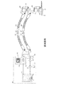
従来技術に属する熱糊塗布装置(図1参照)は、一般的に溶解装置100、1つまたは複数の加熱可能な搬送ホ―ス、および1つまたは複数の加熱可能な塗布弁300を有する。
A hot glue applicator (see FIG. 1) belonging to the prior art generally comprises a
溶解装置100は次のコンポーネントを有する:
・加熱可能なタンク100。このタンクには、熱糊が固体の凝集状態で粒状物として、またはブロックで供給される。このタンクは、熱糊の備蓄と液化のために用いられる。1つまたは複数の加熱ゾーンを有するヒータ111によって、タンクは熱糊が液化するまで加熱される。運転温度を維持するために、加熱ゾーンの数に応じて1つまたは複数の温度センサ112により実際温度が制御のために検出される。
・ポンプ120。このポンプは溶解した熱糊を接続された負荷に搬送する。
・過圧弁130。この過圧弁は作動圧が過剰のときに負荷側の圧力を軽減し、熱糊をタンク110に戻す。
・フィルタ140。このフィルタは、塗布弁を詰らせる危険性のある大きさの粒子が負荷側に達するのを阻止する。
・分配器150。この分配器は複数の油圧接続部を有し、この油圧接続部には加熱可能な搬送ホースを熱糊の供給のために接続することができる。
・複数ゾーンの温度制御および監視部171と操作および表示装置172とを備える電子制御部170。複数ゾーンの温度制御および監視部は、タンク加熱ゾーンが目標温度に達し、これを維持するようにし、複数の外部接続部を有し、接続された加熱可能な搬送ホースおよび加熱可能な塗布弁が目標温度に達し、これを維持するようにし、それを監視する。
The
-
-
An
A
-
An
加熱可能な搬送ホース200は、塗布弁300に液状熱糊を供給するために用いる。搬送ホース200はヒータ210により加熱され、溶解装置100から供給された熱糊を液状に維持する。運転温度を維持するために、温度センサ112によって実際温度が検出され、制御のため制御部170に通知される。
The
加熱可能な塗布弁300は、電気式または電子油圧式に操作される閉鎖機構とノズルを有し、接着すべき製品に塗布される熱糊部分20を調量および位置決めする。塗布弁300はヒータ310により加熱され、溶解装置100から加熱可能な搬送ホース200を介して供給された熱糊を十分に液状にする。そして熱糊を、適用に応じて所要の粘度と温度でノズルを介して塗布することができる。運転温度を維持するために、温度センサ320によって実際温度が検出され、制御のため制御部170に通知される。
The
適用に応じて溶解装置100には、加熱出力および制御特性が可変である加熱可能な搬送ホース200および加熱可能な塗布弁を所要の数だけ接続することができる。熱糊塗布装置の構成は、最初の設置後にも、接着される製品が異なる場合、熱糊が変更される場合、またはコンポーネントの1つが故障して交換部品を接続するときに、その特性が故障したコンポーネントとは異なる場合にはしばしば変更することができる。
Depending on the application, a required number of
熱糊塗布装置の加熱時間と、個々の加熱回路における目標値からの運転温度の制御偏差は、この種の装置の生産性および運転安全性を調整するための重要な適用パラメータである。制御特性を最適化するためには複数ゾーンの温度制御および監視部171が、例えばデッドタイムおよび増幅係数等の制御パラメータの他に、接続されたすべてのコンポーネントの加熱出力および最大温度等の別の技術的データを得ることが必要である。
The heating time of the hot glue applicator and the control deviation of the operating temperature from the target value in each heating circuit are important application parameters for adjusting the productivity and operating safety of this type of device. In order to optimize the control characteristics, the multi-zone temperature control and
複数ゾーン温度制御および監視部171を、接続された種々異なるコンポーネントに対する制御パラメータが手動で入力できるように構成することは公知である。
It is known to configure the multi-zone temperature control and
しかし制御パラメータを手動で入力することは、コンポーネント、熱糊、または接着すべき製品を頻繁に交換する際には面倒であり、エラーの原因となる。 However, manually entering control parameters can be cumbersome and cause errors when frequently changing components, thermal glue, or products to be bonded.
デジタル制御器における自己最適化アルゴリズムは公知である。このアルゴリズムは、手動で、または周期的に、または制御の初期化時にスタートされ、テストプロシージャにより制御パラメータを自動的に検出する。しかしこのアルゴリズムは、加熱回路を接続する際に、目下の値からの制御パラメータの偏差が自動的に識別されるか、または新たな接続の際に最適化サイクルがそれぞれ手動でトリガされる場合にだけ上手くいく。加熱出力および運転温度に対する限界値を、この方法によって求めることはできない。このことはとりわけ、運転中に加熱回路に故障が発生する場合、または故障したコンポーネントが接続される場合にクリティカルである。なぜなら制御部は、警報をトリガせずに制御特性を新たに検出されたパラメータに適合するからである。このことは熱糊塗布の品質に不利に作用し、最大温度を越えると、安全上の重大な危険性を引き起こすことがある。さらにこのアルゴリズムは、接続されたコンポーネントに関するさらなる技術的データなしには、熱糊塗布装置の全体特性、例えばエネルギー消費または全体加熱時間を最適化するための手段を提供しない。 Self-optimizing algorithms in digital controllers are well known. The algorithm is started manually, periodically, or at control initialization, and automatically detects control parameters through a test procedure. However, this algorithm is used when the control circuit deviation from the current value is automatically identified when connecting the heating circuit, or when each optimization cycle is triggered manually during a new connection. Just goes well. Limit values for heating power and operating temperature cannot be determined by this method. This is particularly critical if a failure occurs in the heating circuit during operation or if a failed component is connected. This is because the control unit adapts the control characteristics to the newly detected parameters without triggering an alarm. This adversely affects the quality of the hot glue application and can cause a significant safety hazard if the maximum temperature is exceeded. Furthermore, this algorithm does not provide a means for optimizing the overall properties of the hot glue applicator, such as energy consumption or overall heating time, without further technical data regarding the connected components.
したがって公知の熱糊塗布装置では電子制御部170が、固定的に調整された平均制御パラメータと加熱出力と運転温度に対する最大値によって、または手動でトリガされる自己最適化によって動作する。
Thus, in known thermal glue applicators, the
さらに公知の熱糊塗布装置では、温度センサが短絡とセンサ破損についてしか監視されない。なぜなら、データが固定的に制御部にファイルされている形式のものしか制御に使用されないからである。加熱の監視は行われない。なぜなら加熱パラメータの手動入力は面倒であり、例えば電流センサのようなセンサの付加的な組み込みはコストを上昇させるからである。しかし故障した加熱部の代用として別の特性を備えるものが使用される場合には問題となる。 Furthermore, in known thermal glue applicators, temperature sensors are only monitored for short circuits and sensor breakage. This is because only data in a form in which data is fixedly filed in the control unit is used for control. There is no monitoring of heating. This is because manual input of heating parameters is cumbersome and the additional incorporation of a sensor such as a current sensor increases costs. However, it becomes a problem when a device having other characteristics is used as a substitute for the failed heating unit.
さらなる問題は、使用されるコンポーネントが全体では制限された1つの寿命しか有しておらず、1つだけのコンポーネントの故障が、熱糊塗布装置全体の故障を引き起こすことである。 A further problem is that the components used have only a limited lifetime overall, and failure of only one component causes failure of the entire hot glue applicator.
自動製造装置の使用性を向上させるための公知の方法は、このような装置のコンポーネントを予防的に保守することである。ここでは、統計的評価または実際の実験により得られた、障害なしでの予想運転持続期間でコンポーネントの予防的修理または予防的交換を行うことが前提である。予防的保守を実施するための前提は、個々のコンポーネントの目下の運転持続期間を記録すること、および目下の運転持続期間が得られることである。このためにはログブックに、個別のコンポーネントの運転持続期間が装置全体の運転持続期間と異なることとなるすべてのイベントを手動で記録しなければならず、このことは面倒であり、間違えの原因ともなる。したがって公知の熱糊塗布装置では、溶解装置100の運転持続期間だけが監視される。接続されたコンポーネントの運転持続期間の自動監視は行われない。
A known method for improving the usability of automated manufacturing equipment is to preventively maintain the components of such equipment. Here, it is assumed that the preventive repair or replacement of components is carried out with the expected operation duration without failure, obtained by statistical evaluation or actual experiments. The premise for performing preventive maintenance is to record the current operational duration of the individual components and to obtain the current operational duration. To do this, the logbook must be manually recorded for all events that cause the operating duration of the individual components to differ from the operating duration of the entire system, which is cumbersome and causes the mistakes. It also becomes. Thus, in known hot glue applicators, only the operating duration of the
とりわけ公知の熱糊塗布装置では、コンポーネントにおいて限界温度を超過したことを記録しない。そのためこの情報は診断に使用されない。 In particular, known hot glue applicators do not record that the critical temperature has been exceeded in a component. This information is therefore not used for diagnosis.
発明の基礎とする課題は、コンポーネントを交換した後でも、接着すべき製品の確実な接着を保証し、その運転確実性が高められた熱糊塗布方法および熱糊塗布装置を提供することである。 The problem underlying the invention is to provide a hot glue application method and a hot glue application device that guarantees reliable adhesion of the products to be adhered even after replacement of the components and has improved operational reliability. .
の課題は、請求項1の熱糊塗布装置および独立請求項の熱糊塗布方法によって解決される。本発明の方法および装置の有利な構成は従属請求項に記載されている。 This problem is solved by the hot glue application device of claim 1 and the hot glue application method of the independent claim. Advantageous configurations of the method and device according to the invention are described in the dependent claims.
発明の熱糊塗布装置は、溶解装置と、これに接続されたコンポーネントとして、1つまたは複数の加熱可能な搬送ホースと、1つまたは複数の加熱可能な塗布弁とを有し、これらのコンポーネントは機械により読み取り可能であり、有利には機械により書き込み可能なデータ担体を有している。これによって制御パラメータを自動適合するために、複数ゾーン温度制御および監視部によって必要な技術データがコンポーネント自体に記憶される。この手段に基づき、1つまたは複数のコンポーネントの交換後に制御パラメータが、複数ゾーン温度制御および監視部によって自動適合される。これにより、熱糊塗布装置のすべてのコンポーネントが常に最適の温度で運転される。熱糊塗布装置の改善形態では、温度制御および監視部に接続された加熱回路の運転監視が行われる。制御部170は、接続されたすべてのコンポーネントの制御パラメータおよび技術データを使用するから、付加的なセンサ系なしで、コンポーネントの機能性について推定することができる。このようにして種々異なる形式の温度センサを短絡およびセンサ破損について監視することができ、キャリブレーションを自動的に調整することができる。また温度勾配を評価することによって、公称値が制御部にファイルされていれば、加熱回路の全制御の際に加熱フィラメントまたは加熱カートリッジの部分的短絡を識別することができ、熱損失が過剰である塗布弁が組み込まれたことを識別することができる。
The inventive hot glue applicator comprises a melting device and, as components connected thereto, one or more heatable transport hoses and one or more heatable applicator valves, these components Comprises a machine-readable data carrier, preferably a machine-writable data carrier. In this way, the necessary technical data is stored in the component itself by the multi-zone temperature control and monitoring unit in order to automatically adapt the control parameters. Based on this measure, the control parameters are automatically adapted by the multi-zone temperature control and monitoring unit after replacement of one or more components. This ensures that all components of the hot glue applicator are always operated at the optimum temperature. In the improved form of the hot glue applicator, the operation of the heating circuit connected to the temperature control and monitoring unit is monitored. Since the
保守状態を評価し、熱糊装置を診断するためには、制御部170が運転持続期間に関する情報、溶解装置100の限界温度超過についての情報、および接続された加熱可能な搬送ホース200と加熱可能な塗布弁300についての情報を有することが必要である。ここでは、これらの情報がホースまたは塗布弁自体にファイルされると有利である。これによりすでに使用されているコンポーネントの修理後および接続時に、これまでに達した運転持続期間と、設定された限界パラメータの超過が自動的に制御部170に通報される。運転中に制御部は、コンポーネントに含まれる運転時間カウンタと、限界パラメータに対するデータメモリを周期的に更新する。これにより運転持続期間とコンポーネントが達した限界パラメータを、コンポーネントが溶解装置100に接続されるときに制御部170により問い合わせることができる。またはコンポーネントが例えば修理のために溶解装置100から分離された後、外部から問い合わせることもできる。このためにデータ担体は有利には機械により書き込み可能でもある。
In order to evaluate the maintenance state and diagnose the hot glue device, the
熱糊装置を監視するためには、制御部170が上位の製造装置の制御部と、または外部の監視および診断装置とデータ交換できると有利である。これによりコンポーネントにあるデータ担体から得られた情報をさらなる処理のために使用することができる。さらに装置は通信のために、種々のフィールドバスシステム用またはインターネット用の接続部を有する。これにより、コンポーネントの故障の際に、例えば遠隔診断をインターネットを介して行うことができる。
In order to monitor the hot glue device, it is advantageous if the
公知の熱糊塗布装置は、フィールドバスを介してデータを他の制御部と交換できる装置を有している。しかしこの情報内容は非常に制限されている。なぜなら接続されたコンポーネントのデータは使用されないからである。 A known hot glue application device has a device capable of exchanging data with another control unit via a field bus. However, this information content is very limited. This is because the data of the connected component is not used.
制御部170は、溶解装置100の加熱回路、接続された加熱可能な搬送ホース200、ならびに接続された加熱可能な塗布弁300を制御および監視するための通常のコンポーネントの他に、有線接続された装置173(図2参照)または無線装置173(図3参照)を、接続されたコンポーネントにあるデータ担体との通信のために有する。搬送ホース200はそれぞれ1つまたは複数の機械により読み出し可能および有利には書き込み可能なデータ担体230を有し、塗布弁300はそれぞれ1つまた複数の機械により読み出し可能および有利には書き込み可能なデータ担体330、例えばマイクロプロセッサシステム、記憶装置、コーディングまたはRFIDを有する。RFIDは、有線または無線で、または光学的に、または他の適切な手段によってデータを装置173に伝送し、有利にはこの装置から受信することができる。データ担体には、コンポーネントの製造または修理の際に外部の書き込みおよび読み出しユニット400によって、形式固有の制御パラメータ、例えばデッドタイムおよび増幅係数、ならびにさらなる技術データ、例えば製造日付、平均寿命、加熱出力および最大温度が書き込まれる。コンポーネントが溶解装置100に接続されていれば、データ担体は初期化の際および/または周期的に、およびシステム構成の変更時に、それらのデータを装置173に通知する。これらのデータを制御部170は、接続されたコンポーネントおよびシステム全体を最適に制御し、監視するために使用する。装置173は、初期化の際および/または周期的に、およびシステム構成の変更時に、例えば最大目標パラメータおよび実際パラメータ、または経過した運転時間等のデータを接続されたコンポーネントのデータ担体に通知する。そしてこれらのデータを有利には診断および予防的保守のために使用することができる。
The
さらに通信装置173は接続部175を有する。この接続部175は、フィールドバスを介して上位の制御部と、またはインターネットを介して外部の監視装置とデータ交換するためのものである。これにより、コンポーネントの故障の際に例えば警報信号を機械の司令所に通知し、遠隔診断をインターネットを介して行うことができる。
Further, the
Claims (12)
前記コンポーネントは、1つまたは複数の加熱可能な搬送ホース(200)と1つまたは複数の加熱可能な塗布弁(300)とを含み、
前記熱糊塗布装置は、前記溶解装置(100)の加熱回路および接続されたコンポーネントの制御および監視のために用いられる制御部(170)を備え、
前記搬送ホース(200)および前記塗布弁(300)は、それぞれ、機械により読み出し可能なデータ担体(230,330)を含み、
該データ担体は、複数ゾーン温度制御および監視部による制御パラメータの自動適合のために必要な技術データを記憶し、
前記制御部(170)は、前記コンポーネントにある前記データ担体(230,330)との通信のための通信装置(173,174)を有する、
ことを特徴とする熱糊塗布装置。 In a hot glue applicator comprising a melting device (100) and components connected to the melting device,
The component includes one or more heatable transfer hoses (200) and one or more heatable application valves (300);
The hot glue applicator comprises a controller (170) used for control and monitoring of the heating circuit and connected components of the melting device (100),
The transfer hose (200) and the application valve (300) each include a data carrier (230, 330) readable by a machine,
The data carrier stores technical data necessary for automatic adaptation of control parameters by a multi-zone temperature control and monitoring unit,
The control unit (170) comprises communication devices (173, 174) for communication with the data carriers (230, 330) in the component,
A hot glue application device characterized by that.
前記データ担体(230,330)は機械により書き込み可能である熱糊塗布装置。 The hot glue application device according to claim 1,
The data carrier (230, 330) is a hot glue applicator that is writable by a machine.
前記機械により読み出し可能なデータ担体(230,330)は、マイクロプロセッサシステムを有する熱糊塗布装置。 The hot glue application device according to claim 1 or 2,
The machine-readable data carrier (230, 330) is a thermal glue applicator having a microprocessor system.
前記機械により読み出し可能なデータ担体(230,330)は、1つまたは複数の半導体メモリを有する熱糊塗布装置。 The hot glue application device according to any one of claims 1 to 3,
The data carrier (230, 330) readable by the machine is a hot glue applicator having one or more semiconductor memories.
前記機械により読み出し可能なデータ担体は、磁気的に読み出し可能および/または書き込み可能なメモリまたは符号担体を有する熱糊塗布装置。 The hot glue application device according to any one of claims 1 to 4,
The data carrier readable by the machine is a hot glue applicator having a magnetically readable and / or writable memory or code carrier.
前記機械により読み出し可能なデータ担体(230,330)は、光学的に読み出し可能および/または書き込み可能な符号担体を有する熱糊塗布装置。 The hot glue application device according to any one of claims 1 to 5,
A thermal glue applicator, wherein the machine-readable data carrier (230, 330) comprises an optically readable and / or writable code carrier.
前記符号担体は、バーコード、2Dコード、または3Dコードを含む熱糊塗布装置。 The hot glue application device according to claim 6,
The code carrier is a hot glue application device including a bar code, 2D code, or 3D code.
前記制御部(170)の通信装置(173,174)と、接続されたコンポーネントにある前記データ担体(230,330)との間の通信は、有線接続で前記溶解装置(100)の接続ソケットを介して、または無線で電磁的、磁気的、音響的、または光学的に行われる熱糊塗布装置。 The hot glue application device according to any one of claims 1 to 7,
Communication between the communication device (173, 174) of the control unit (170) and the data carrier (230, 330) in the connected component is performed by connecting the connection socket of the melting device (100) with a wired connection. A thermal glue applicator that is electromagnetically, magnetically, acoustically or optically performed via or wirelessly.
前記通信装置(173,174)は接続部を有し、該接続部はフィールドバスを介して上位の制御部と、またはインターネットを介して外部の監視装置とデータ交換することができる熱糊塗布装置。 The hot glue application device according to any one of claims 1 to 8,
The communication device (173, 174) has a connection unit, and the connection unit can exchange data with a host control unit via a fieldbus or an external monitoring device via the Internet. .
前記コンポーネントは、1つまたは複数の加熱可能な搬送ホース(200)と1つまたは複数の加熱可能な塗布弁(300)とを含み、
前記溶解装置は制御部(170)を有し、
前記搬送ホースおよび塗布弁はそれぞれ機械により読み出しおよび/または機械により書き込み可能なデータ担体を有し、
該データ担体は、複数ゾーン温度制御および監視部による制御パラメータの自動適合のために必要な技術データを記憶する形式の方法において、
前記制御部(170)は、初期化の際に有線または無線で、前記接続されたコンポーネントにあるデータ担体(230,330)と通信し、および/または
前記制御部(170)は、周期的に有線または無線で、前記接続されたコンポーネントにあるデータ担体(230,330)と通信し、
前記制御部(170)はシステム構成の変更時に有線または無線で、前記接続されたコンポーネントにあるデータ担体(230,330)と通信し、
前記制御部(170)は、接続されたコンポーネントからデータを受信し、該データを前記溶解装置の加熱回路の制御および監視を最適化するために使用することを特徴とする方法。 A method for controlling and monitoring a hot glue applicator comprising a melting apparatus (100) and components connected to the melting apparatus,
The component includes one or more heatable transfer hoses (200) and one or more heatable application valves (300);
The dissolution apparatus has a control unit (170),
The transfer hose and the application valve each have a data carrier which can be read and / or written by a machine;
The data carrier is a method in the form of storing technical data required for automatic adaptation of control parameters by a multi-zone temperature control and monitoring unit,
The controller (170) communicates with the data carriers (230, 330) in the connected components, either wired or wirelessly during initialization, and / or the controller (170) periodically Communicate with the data carrier (230, 330) in the connected component, wired or wireless,
The controller (170) communicates with the data carriers (230, 330) in the connected components in a wired or wireless manner when the system configuration is changed,
Method according to claim 1, characterized in that the controller (170) receives data from connected components and uses the data to optimize the control and monitoring of the heating circuit of the melting apparatus.
前記制御部(170)は、前記データ担体(230,330)にあるデータを前記接続されたコンポーネントに伝送し、該データは該コンポーネントの診断および保守の最適化のために使用される方法。 The method of claim 10, comprising:
The method wherein the controller (170) transmits data on the data carrier (230, 330) to the connected component, which data is used for the diagnosis and maintenance optimization of the component.
前記制御部はフィールドバスを介して上位の制御部と、またはインターネットを介して外部の監視装置とデータを交換し、該データは熱糊塗布装置の監視を最適化し、エラーの場合に遠隔診断を可能にするために使用される方法。 12. A method according to claim 10 or 11, comprising:
The control unit exchanges data with a host control unit via a field bus or an external monitoring device via the Internet, and the data optimizes the monitoring of the hot glue application device, and performs remote diagnosis in case of an error. The method used to make it possible.
Applications Claiming Priority (3)
| Application Number | Priority Date | Filing Date | Title |
|---|---|---|---|
| DE102006039839.4A DE102006039839B4 (en) | 2006-08-25 | 2006-08-25 | Hot glue application system and method for controlling and monitoring the hot glue application system |
| DE102006039839.4 | 2006-08-25 | ||
| PCT/EP2007/006956 WO2008022708A1 (en) | 2006-08-25 | 2007-08-07 | Hot-glue application system and method for controlling and monitoring the hot-glue application system |
Publications (2)
| Publication Number | Publication Date |
|---|---|
| JP2010501324A JP2010501324A (en) | 2010-01-21 |
| JP5436210B2 true JP5436210B2 (en) | 2014-03-05 |
Family
ID=38535427
Family Applications (1)
| Application Number | Title | Priority Date | Filing Date |
|---|---|---|---|
| JP2009524927A Expired - Fee Related JP5436210B2 (en) | 2006-08-25 | 2007-08-07 | Thermal glue applicator and control and monitoring method for thermal glue applicator |
Country Status (7)
| Country | Link |
|---|---|
| US (2) | US9840643B2 (en) |
| EP (1) | EP2054785B1 (en) |
| JP (1) | JP5436210B2 (en) |
| CN (1) | CN101506751B (en) |
| DE (2) | DE202006021238U1 (en) |
| ES (1) | ES2465669T3 (en) |
| WO (1) | WO2008022708A1 (en) |
Families Citing this family (47)
| Publication number | Priority date | Publication date | Assignee | Title |
|---|---|---|---|---|
| DE102009033030A1 (en) * | 2009-07-02 | 2011-01-05 | Krones Ag | Leimaufbereitungsvorrichtung |
| EP2404679B1 (en) * | 2010-07-07 | 2017-08-30 | Henkel AG & Co. KGaA | Delivery unit for an application system |
| DE102011004024A1 (en) | 2011-02-14 | 2012-08-16 | Illinois Tool Works Inc. | Control device for a powder spray coating device |
| EP2532444A1 (en) * | 2011-06-07 | 2012-12-12 | Baumer hhs GmbH | Method and device for applying fluid or viscous media |
| DE102011110281A1 (en) | 2011-06-22 | 2012-12-27 | Baumer Hhs Gmbh | Applicator device for applying of flowable substances, has compressible material, which is arranged on layer for accommodating installation pressure, where compressible layer is made of open-cell, closed-cell or mixed-cell foam |
| CN103826759A (en) * | 2011-09-13 | 2014-05-28 | 格瑞克明尼苏达有限公司 | Method for preventing pack-out in pumping system |
| EP3597309B1 (en) | 2011-10-27 | 2022-03-23 | Graco Minnesota Inc. | Melter |
| IN2014DN03195A (en) | 2011-10-27 | 2015-05-22 | Graco Minnesota Inc | |
| US9061316B2 (en) * | 2011-10-28 | 2015-06-23 | Nordson Corporation | Mountable device for dispensing heated adhesive |
| US10642286B2 (en) | 2012-04-20 | 2020-05-05 | Nordson Corporation | Device, system, and method for tracking the configuration or operational history of a nozzle in a fluid jetting system |
| DE202012004262U1 (en) * | 2012-05-02 | 2013-08-08 | Baumer Hhs Gmbh | hot glue application system |
| DE102012108328B4 (en) | 2012-09-07 | 2019-07-18 | Baumer Hhs Gmbh | hot glue application system |
| US10099242B2 (en) | 2012-09-20 | 2018-10-16 | Nordson Corporation | Adhesive melter having pump mounted into heated housing |
| US9169088B2 (en) | 2012-09-20 | 2015-10-27 | Nordson Corporation | Adhesive dispensing device having optimized cyclonic separator unit |
| US9304028B2 (en) | 2012-09-20 | 2016-04-05 | Nordson Corporation | Adhesive dispensing device having optimized reservoir and capacitive level sensor |
| US9120115B2 (en) | 2012-10-25 | 2015-09-01 | Nordson Corporation | Dispensing systems and methods for monitoring actuation signals for diagnostics |
| US9200741B2 (en) | 2012-10-25 | 2015-12-01 | Nordson Corporation | Adhesive dispensing system and method using smart melt heater control |
| US9243626B2 (en) | 2012-11-19 | 2016-01-26 | Nordson Corporation | Adhesive dispensing system and method including a pump with integrated diagnostics |
| CN104981854A (en) | 2013-02-11 | 2015-10-14 | 格瑞克明尼苏达有限公司 | Remote monitoring for fluid applicator system |
| US10969805B2 (en) | 2013-02-11 | 2021-04-06 | Graco Minnesota Inc. | Paint sprayer distributed control and output volume monitoring architectures |
| US9574714B2 (en) | 2013-07-29 | 2017-02-21 | Nordson Corporation | Adhesive melter and method having predictive maintenance for exhaust air filter |
| DE102013218020A1 (en) * | 2013-09-10 | 2015-03-12 | Krones Ag | Method for the guided conversion of a treatment machine |
| US9615405B2 (en) * | 2013-09-16 | 2017-04-04 | Nordson Corporation | Heat exchange devices, liquid adhesive systems, and related methods |
| US9731486B2 (en) | 2013-09-16 | 2017-08-15 | Nordson Corporation | Heat exchange device with ring shaped thin slit section for use in liquid adhesive systems and related methods |
| DE102013111302A1 (en) | 2013-10-14 | 2015-04-16 | Baumer Hhs Gmbh | Application head, application system and method for producing an application head |
| DE102013112686A1 (en) | 2013-11-18 | 2015-05-21 | Baumer Hhs Gmbh | Hot glue application system and method |
| DE102013112754A1 (en) | 2013-11-19 | 2015-05-21 | Baumer Hhs Gmbh | Apparatus for applying a viscous or fluid coating medium and method for producing such a device |
| DE102014017895A1 (en) | 2014-12-03 | 2016-06-09 | Dürr Systems GmbH | Application system component with transponder and / or wear detection device |
| EP3051373B1 (en) * | 2015-02-02 | 2019-05-08 | Siemens Aktiengesellschaft | Exchange of a defective system component in an automation assembly |
| US9796492B2 (en) | 2015-03-12 | 2017-10-24 | Graco Minnesota Inc. | Manual check valve for priming a collapsible fluid liner for a sprayer |
| USD823912S1 (en) * | 2015-09-25 | 2018-07-24 | Baumer Hhs Gmbh | Glue application device |
| DE102015015292B4 (en) | 2015-11-30 | 2019-02-21 | Baumer Hhs Gmbh | Applicator and method for applying viscous media |
| DE102016006365B3 (en) * | 2016-05-30 | 2017-05-18 | Baumer Hhs Gmbh | Packaging machine and control method of a packaging machine |
| DE102016006364B4 (en) * | 2016-05-30 | 2017-12-14 | Baumer Hhs Gmbh | hot glue application system |
| DE102016006363B3 (en) * | 2016-05-30 | 2017-05-18 | Baumer Hhs Gmbh | Production machine with a hot glue application system and control method of a hot glue application system of a production machine |
| US20180017200A1 (en) | 2016-07-15 | 2018-01-18 | Nordson Corporation | Adhesive transfer hose having a barrier layer and method of use |
| DE102017002724A1 (en) | 2017-03-21 | 2018-09-27 | Baumer Hhs Gmbh | Apparatus and method for collecting consumption data for a hot glue system |
| DE102017003020B4 (en) | 2017-03-29 | 2022-05-25 | Baumer Hhs Gmbh | Method and device for the safe operation of a hot melt system |
| SG11201909169SA (en) * | 2017-04-28 | 2019-10-30 | Musashi Engineering Inc | Cable unit, and liquid material supply device and application device in which said cable unit is used |
| DE102017006459A1 (en) * | 2017-07-07 | 2019-01-10 | Baumer Hhs Gmbh | System, in particular hot glue application system and method, in particular hot glue application method |
| DE102017119439A1 (en) * | 2017-08-24 | 2019-02-28 | Khs Gmbh | A method of controlling the amount of adhesive to be applied to a carrier |
| DE102017010454B3 (en) | 2017-11-13 | 2019-03-21 | Baumer Hhs Gmbh | Apparatus and method for controlling the granule feed of a granule supply system |
| DE102018108273A1 (en) | 2018-04-09 | 2019-10-10 | Baumer Hhs Gmbh | Method for joining two packaging material substrate layers |
| JP2021527245A (en) | 2018-06-04 | 2021-10-11 | ノードソン コーポレーションNordson Corporation | Liquid discharge system Communication system and method |
| US20220234062A1 (en) | 2019-05-31 | 2022-07-28 | Graco Minnesota Inc. | Handheld fluid sprayer |
| CN112676101B (en) * | 2020-12-10 | 2022-04-12 | 哈尔滨工业大学 | Compact high-viscosity engine shell lining throwing and coating device |
| DE102021115091A1 (en) | 2021-06-11 | 2022-12-15 | Baumer Hhs Gmbh | hot glue application system |
Family Cites Families (38)
| Publication number | Priority date | Publication date | Assignee | Title |
|---|---|---|---|---|
| JPS53122762U (en) * | 1977-03-08 | 1978-09-29 | ||
| DE3050226C1 (en) * | 1980-02-07 | 1985-02-14 | Daimler-Benz Ag, 7000 Stuttgart | Device for recognizing the spray nozzle attached when coating cavities and corresponding quantity allocation |
| JPS5968538A (en) | 1982-10-12 | 1984-04-18 | Honda Motor Co Ltd | Slip preventive device for wheel |
| GB2142172B (en) | 1983-06-23 | 1986-12-03 | Oxley Dev Co Ltd | Elapsed time and maintenance monitoring system |
| JPH0754182Y2 (en) * | 1989-02-17 | 1995-12-13 | 株式会社松井製作所 | Pipe identification device |
| DE3912405C1 (en) * | 1989-04-15 | 1990-10-31 | B. Braun Melsungen Ag, 3508 Melsungen, De | |
| JP2527926Y2 (en) * | 1991-09-05 | 1997-03-05 | 徳興 中橋 | Hot melt applicator |
| JPH06313500A (en) * | 1993-04-30 | 1994-11-08 | Suntory Ltd | Connection condition sensing method for piping system |
| JP2713687B2 (en) * | 1993-08-06 | 1998-02-16 | 日立テクノエンジニアリング株式会社 | Paste coating machine |
| CA2131949A1 (en) * | 1993-09-29 | 1995-03-30 | Wesley C. Fort | Continuous hot melt adhesive applicator |
| US5604681A (en) * | 1994-06-03 | 1997-02-18 | Dover Corporation | Coupler identification systems |
| US5718767A (en) | 1994-10-05 | 1998-02-17 | Nordson Corporation | Distributed control system for powder coating system |
| CA2187985A1 (en) | 1995-11-02 | 1997-05-03 | Scott B. Means | Distributed system for controlling application of molten thermoplastic material |
| JP3681815B2 (en) * | 1996-04-25 | 2005-08-10 | 横浜ゴム株式会社 | hose |
| US6272401B1 (en) * | 1997-07-23 | 2001-08-07 | Dresser Industries, Inc. | Valve positioner system |
| ES2161069T3 (en) * | 1997-09-22 | 2001-11-16 | Bartec Componenten & Syst Gmbh | PROCEDURE AND SECURITY SYSTEM TO INSURE A PRODUCT WITH FLUIDITY. |
| JPH11276946A (en) * | 1998-03-24 | 1999-10-12 | Basf Corp | Controller and control of coating equipment and recording medium for controlling coating equipment |
| US6125868A (en) * | 1998-06-18 | 2000-10-03 | Hydra-Stop, Inc. | Method and apparatus for maintaining valves in a water distribution system |
| JP2000048066A (en) | 1998-07-27 | 2000-02-18 | Hitachi Ltd | Life cycle management method, its system and product |
| DE19917222A1 (en) | 1999-04-16 | 2000-11-02 | Schrauben Betzer Gmbh & Co Kg | Screw and device for handling such a screw |
| US6499629B1 (en) | 1999-05-28 | 2002-12-31 | Nordson Corporation | Dispensing apparatus for viscous liquids |
| DE19938405A1 (en) * | 1999-08-13 | 2001-02-22 | Ruetz Technologies | Device and method for applying / applying fragrances |
| US6758423B1 (en) | 1999-09-17 | 2004-07-06 | Nordson Corporation | Spray gun with data device and method of control |
| US6514569B1 (en) * | 2000-01-14 | 2003-02-04 | Kenneth Crouch | Variable volume positive displacement dispensing system and method |
| JP2001246307A (en) * | 2000-03-08 | 2001-09-11 | Suntool Corp | Heating hose in hot melt applying device |
| US20020030581A1 (en) * | 2000-04-14 | 2002-03-14 | Janiak Martin J. | Optical and smart card identification reader |
| JPWO2002061514A1 (en) | 2001-01-30 | 2004-06-03 | 株式会社ニコン | Diagnostic device, information collecting device, diagnostic system and remote maintenance system |
| CN101118030B (en) * | 2001-10-29 | 2013-01-09 | 诺德森公司 | Heat-welding adhesive quantitative dosing device |
| US6812707B2 (en) * | 2001-11-27 | 2004-11-02 | Mitsubishi Materials Corporation | Detection element for objects and detection device using the same |
| JP2003243286A (en) * | 2002-02-14 | 2003-08-29 | Dainippon Screen Mfg Co Ltd | Substrate processing apparatus |
| JP2004025505A (en) * | 2002-06-21 | 2004-01-29 | Seiko Epson Corp | Ejector, ejecting method, ejection control program, medium recording that program, device having basic material, electrooptic device, system and method for fabricating device having substrate |
| SE525187C2 (en) | 2003-03-10 | 2004-12-21 | Atlas Copco Tools Ab | Tool system comprising a multipart cable with an electronic memory |
| DE602004020616D1 (en) | 2003-05-09 | 2009-05-28 | Intellipack Inc | System for controlling and remote monitoring of a foam dispenser |
| DE10335035A1 (en) | 2003-08-01 | 2005-03-03 | Siemens Ag | System and method for identifying automation components |
| US20050095359A1 (en) * | 2003-10-31 | 2005-05-05 | Nordson Corporation | Hot melt adhesive system and method using machine readable information |
| US7460278B2 (en) * | 2004-01-29 | 2008-12-02 | Seiko Epson Corporation | 3-Dimensional dot code for paper storage |
| WO2005075088A2 (en) | 2004-01-30 | 2005-08-18 | Nordson Corporation | Material application system having component with wireless identification capabilities |
| DE102004050383A1 (en) | 2004-10-15 | 2006-04-27 | Siemens Ag | Transfer of data to and from automation components |
-
2006
- 2006-08-25 DE DE202006021238.8U patent/DE202006021238U1/en not_active Expired - Lifetime
- 2006-08-25 DE DE102006039839.4A patent/DE102006039839B4/en not_active Expired - Fee Related
-
2007
- 2007-08-07 WO PCT/EP2007/006956 patent/WO2008022708A1/en active Application Filing
- 2007-08-07 EP EP07786592.1A patent/EP2054785B1/en not_active Revoked
- 2007-08-07 CN CN2007800316604A patent/CN101506751B/en not_active Expired - Fee Related
- 2007-08-07 US US12/310,453 patent/US9840643B2/en active Active
- 2007-08-07 ES ES07786592.1T patent/ES2465669T3/en active Active
- 2007-08-07 JP JP2009524927A patent/JP5436210B2/en not_active Expired - Fee Related
-
2013
- 2013-12-11 US US14/102,527 patent/US20140100685A1/en not_active Abandoned
Also Published As
| Publication number | Publication date |
|---|---|
| ES2465669T3 (en) | 2014-06-06 |
| EP2054785B1 (en) | 2014-03-26 |
| CN101506751B (en) | 2013-01-09 |
| JP2010501324A (en) | 2010-01-21 |
| CN101506751A (en) | 2009-08-12 |
| DE202006021238U1 (en) | 2014-01-29 |
| DE102006039839B4 (en) | 2019-11-28 |
| US9840643B2 (en) | 2017-12-12 |
| US20140100685A1 (en) | 2014-04-10 |
| DE102006039839A1 (en) | 2008-03-13 |
| WO2008022708A1 (en) | 2008-02-28 |
| US20090285983A1 (en) | 2009-11-19 |
| EP2054785A1 (en) | 2009-05-06 |
Similar Documents
| Publication | Publication Date | Title |
|---|---|---|
| JP5436210B2 (en) | Thermal glue applicator and control and monitoring method for thermal glue applicator | |
| EP1877875B1 (en) | Redundant control circuit for hot melt adhesive hose assembly heater circuits and temperature sensors | |
| US8097836B2 (en) | Inferential temperature control system | |
| US8784935B2 (en) | Hot melt adhesive system and method using machine readable information | |
| JP6332936B2 (en) | Adhesive dispensing system and method for operating the system | |
| JP5143741B2 (en) | Process field device temperature control | |
| US20060289566A1 (en) | Control circuits for hot melt adhesive heater circuits and applicator heads | |
| US7084377B2 (en) | Heated device and method of redundant temperature sensing | |
| EP1880256B1 (en) | Redundant control circuit for hot melt adhesive hose assembly heater circuits and temperature sensors | |
| JP3687511B2 (en) | Water heater system | |
| US11268592B2 (en) | Automatic control panel for vulcanizing press and method of using thereof | |
| JP2002366683A (en) | Maintenance system and equipment |
Legal Events
| Date | Code | Title | Description |
|---|---|---|---|
| RD04 | Notification of resignation of power of attorney |
Free format text: JAPANESE INTERMEDIATE CODE: A7424 Effective date: 20101228 Free format text: JAPANESE INTERMEDIATE CODE: A7424 Effective date: 20101227 |
|
| A131 | Notification of reasons for refusal |
Free format text: JAPANESE INTERMEDIATE CODE: A131 Effective date: 20120203 |
|
| A601 | Written request for extension of time |
Free format text: JAPANESE INTERMEDIATE CODE: A601 Effective date: 20120502 |
|
| A602 | Written permission of extension of time |
Free format text: JAPANESE INTERMEDIATE CODE: A602 Effective date: 20120511 |
|
| A521 | Request for written amendment filed |
Free format text: JAPANESE INTERMEDIATE CODE: A523 Effective date: 20120621 |
|
| A02 | Decision of refusal |
Free format text: JAPANESE INTERMEDIATE CODE: A02 Effective date: 20130327 |
|
| A521 | Request for written amendment filed |
Free format text: JAPANESE INTERMEDIATE CODE: A523 Effective date: 20130719 |
|
| A911 | Transfer to examiner for re-examination before appeal (zenchi) |
Free format text: JAPANESE INTERMEDIATE CODE: A911 Effective date: 20130726 |
|
| RD13 | Notification of appointment of power of sub attorney |
Free format text: JAPANESE INTERMEDIATE CODE: A7433 Effective date: 20130905 |
|
| A521 | Request for written amendment filed |
Free format text: JAPANESE INTERMEDIATE CODE: A821 Effective date: 20130905 |
|
| A131 | Notification of reasons for refusal |
Free format text: JAPANESE INTERMEDIATE CODE: A131 Effective date: 20131015 |
|
| A521 | Request for written amendment filed |
Free format text: JAPANESE INTERMEDIATE CODE: A523 Effective date: 20131018 |
|
| TRDD | Decision of grant or rejection written | ||
| A01 | Written decision to grant a patent or to grant a registration (utility model) |
Free format text: JAPANESE INTERMEDIATE CODE: A01 Effective date: 20131111 |
|
| A61 | First payment of annual fees (during grant procedure) |
Free format text: JAPANESE INTERMEDIATE CODE: A61 Effective date: 20131210 |
|
| R150 | Certificate of patent or registration of utility model |
Ref document number: 5436210 Country of ref document: JP Free format text: JAPANESE INTERMEDIATE CODE: R150 Free format text: JAPANESE INTERMEDIATE CODE: R150 |
|
| R250 | Receipt of annual fees |
Free format text: JAPANESE INTERMEDIATE CODE: R250 |
|
| R250 | Receipt of annual fees |
Free format text: JAPANESE INTERMEDIATE CODE: R250 |
|
| R250 | Receipt of annual fees |
Free format text: JAPANESE INTERMEDIATE CODE: R250 |
|
| R250 | Receipt of annual fees |
Free format text: JAPANESE INTERMEDIATE CODE: R250 |
|
| R250 | Receipt of annual fees |
Free format text: JAPANESE INTERMEDIATE CODE: R250 |
|
| R250 | Receipt of annual fees |
Free format text: JAPANESE INTERMEDIATE CODE: R250 |
|
| LAPS | Cancellation because of no payment of annual fees |