JP4664676B2 - System for automatically containing and distributing individual elements - Google Patents
System for automatically containing and distributing individual elements Download PDFInfo
- Publication number
- JP4664676B2 JP4664676B2 JP2004532991A JP2004532991A JP4664676B2 JP 4664676 B2 JP4664676 B2 JP 4664676B2 JP 2004532991 A JP2004532991 A JP 2004532991A JP 2004532991 A JP2004532991 A JP 2004532991A JP 4664676 B2 JP4664676 B2 JP 4664676B2
- Authority
- JP
- Japan
- Prior art keywords
- conveyor
- elements
- item
- drum
- assembly
- Prior art date
- Legal status (The legal status is an assumption and is not a legal conclusion. Google has not performed a legal analysis and makes no representation as to the accuracy of the status listed.)
- Expired - Lifetime
Links
- 230000007246 mechanism Effects 0.000 claims abstract description 26
- 229940079593 drug Drugs 0.000 abstract description 19
- 239000003814 drug Substances 0.000 abstract description 19
- 238000012546 transfer Methods 0.000 abstract description 6
- 238000002483 medication Methods 0.000 abstract description 5
- 230000000712 assembly Effects 0.000 description 7
- 238000000429 assembly Methods 0.000 description 7
- 238000000034 method Methods 0.000 description 6
- 238000010586 diagram Methods 0.000 description 5
- 230000009471 action Effects 0.000 description 4
- 230000008569 process Effects 0.000 description 4
- 239000007788 liquid Substances 0.000 description 3
- 239000002184 metal Substances 0.000 description 3
- 238000012986 modification Methods 0.000 description 3
- 230000004048 modification Effects 0.000 description 3
- 238000012545 processing Methods 0.000 description 3
- 230000004308 accommodation Effects 0.000 description 2
- 210000005069 ears Anatomy 0.000 description 2
- 239000000463 material Substances 0.000 description 2
- 229910001220 stainless steel Inorganic materials 0.000 description 2
- 239000010935 stainless steel Substances 0.000 description 2
- 229920002972 Acrylic fiber Polymers 0.000 description 1
- 230000008859 change Effects 0.000 description 1
- 238000013461 design Methods 0.000 description 1
- 238000009513 drug distribution Methods 0.000 description 1
- 230000007717 exclusion Effects 0.000 description 1
- 230000000977 initiatory effect Effects 0.000 description 1
- 238000007689 inspection Methods 0.000 description 1
- 230000005389 magnetism Effects 0.000 description 1
- 238000007726 management method Methods 0.000 description 1
- 229940126701 oral medication Drugs 0.000 description 1
- 238000004806 packaging method and process Methods 0.000 description 1
- 238000003825 pressing Methods 0.000 description 1
- 238000000926 separation method Methods 0.000 description 1
- 239000007787 solid Substances 0.000 description 1
- 238000006467 substitution reaction Methods 0.000 description 1
- 230000000007 visual effect Effects 0.000 description 1
Images


Classifications
-
- G—PHYSICS
- G07—CHECKING-DEVICES
- G07F—COIN-FREED OR LIKE APPARATUS
- G07F17/00—Coin-freed apparatus for hiring articles; Coin-freed facilities or services
- G07F17/0092—Coin-freed apparatus for hiring articles; Coin-freed facilities or services for assembling and dispensing of pharmaceutical articles
-
- B—PERFORMING OPERATIONS; TRANSPORTING
- B65—CONVEYING; PACKING; STORING; HANDLING THIN OR FILAMENTARY MATERIAL
- B65G—TRANSPORT OR STORAGE DEVICES, e.g. CONVEYORS FOR LOADING OR TIPPING, SHOP CONVEYOR SYSTEMS OR PNEUMATIC TUBE CONVEYORS
- B65G1/00—Storing articles, individually or in orderly arrangement, in warehouses or magazines
- B65G1/02—Storage devices
- B65G1/04—Storage devices mechanical
- B65G1/0407—Storage devices mechanical using stacker cranes
- B65G1/0435—Storage devices mechanical using stacker cranes with pulling or pushing means on either stacking crane or stacking area
-
- B—PERFORMING OPERATIONS; TRANSPORTING
- B65—CONVEYING; PACKING; STORING; HANDLING THIN OR FILAMENTARY MATERIAL
- B65G—TRANSPORT OR STORAGE DEVICES, e.g. CONVEYORS FOR LOADING OR TIPPING, SHOP CONVEYOR SYSTEMS OR PNEUMATIC TUBE CONVEYORS
- B65G1/00—Storing articles, individually or in orderly arrangement, in warehouses or magazines
- B65G1/02—Storage devices
- B65G1/04—Storage devices mechanical
- B65G1/137—Storage devices mechanical with arrangements or automatic control means for selecting which articles are to be removed
- B65G1/1373—Storage devices mechanical with arrangements or automatic control means for selecting which articles are to be removed for fulfilling orders in warehouses
- B65G1/1378—Storage devices mechanical with arrangements or automatic control means for selecting which articles are to be removed for fulfilling orders in warehouses the orders being assembled on fixed commissioning areas remote from the storage areas
-
- B—PERFORMING OPERATIONS; TRANSPORTING
- B65—CONVEYING; PACKING; STORING; HANDLING THIN OR FILAMENTARY MATERIAL
- B65G—TRANSPORT OR STORAGE DEVICES, e.g. CONVEYORS FOR LOADING OR TIPPING, SHOP CONVEYOR SYSTEMS OR PNEUMATIC TUBE CONVEYORS
- B65G25/00—Conveyors comprising a cyclically-moving, e.g. reciprocating, carrier or impeller which is disengaged from the load during the return part of its movement
- B65G25/02—Conveyors comprising a cyclically-moving, e.g. reciprocating, carrier or impeller which is disengaged from the load during the return part of its movement the carrier or impeller having different forward and return paths of movement, e.g. walking beam conveyors
-
- G—PHYSICS
- G07—CHECKING-DEVICES
- G07F—COIN-FREED OR LIKE APPARATUS
- G07F11/00—Coin-freed apparatus for dispensing, or the like, discrete articles
- G07F11/02—Coin-freed apparatus for dispensing, or the like, discrete articles from non-movable magazines
- G07F11/04—Coin-freed apparatus for dispensing, or the like, discrete articles from non-movable magazines in which magazines the articles are stored one vertically above the other
- G07F11/16—Delivery means
- G07F11/24—Rotary or oscillatory members
-
- G—PHYSICS
- G07—CHECKING-DEVICES
- G07F—COIN-FREED OR LIKE APPARATUS
- G07F11/00—Coin-freed apparatus for dispensing, or the like, discrete articles
- G07F11/02—Coin-freed apparatus for dispensing, or the like, discrete articles from non-movable magazines
- G07F11/04—Coin-freed apparatus for dispensing, or the like, discrete articles from non-movable magazines in which magazines the articles are stored one vertically above the other
- G07F11/16—Delivery means
- G07F11/26—Endless bands
-
- G—PHYSICS
- G07—CHECKING-DEVICES
- G07F—COIN-FREED OR LIKE APPARATUS
- G07F11/00—Coin-freed apparatus for dispensing, or the like, discrete articles
- G07F11/02—Coin-freed apparatus for dispensing, or the like, discrete articles from non-movable magazines
- G07F11/44—Coin-freed apparatus for dispensing, or the like, discrete articles from non-movable magazines in which magazines the articles are stored in bulk
-
- G—PHYSICS
- G07—CHECKING-DEVICES
- G07F—COIN-FREED OR LIKE APPARATUS
- G07F11/00—Coin-freed apparatus for dispensing, or the like, discrete articles
- G07F11/46—Coin-freed apparatus for dispensing, or the like, discrete articles from movable storage containers or supports
- G07F11/50—Coin-freed apparatus for dispensing, or the like, discrete articles from movable storage containers or supports the storage containers or supports being rotatably mounted
- G07F11/54—Coin-freed apparatus for dispensing, or the like, discrete articles from movable storage containers or supports the storage containers or supports being rotatably mounted about vertical axes
-
- G—PHYSICS
- G07—CHECKING-DEVICES
- G07F—COIN-FREED OR LIKE APPARATUS
- G07F11/00—Coin-freed apparatus for dispensing, or the like, discrete articles
- G07F11/46—Coin-freed apparatus for dispensing, or the like, discrete articles from movable storage containers or supports
- G07F11/58—Coin-freed apparatus for dispensing, or the like, discrete articles from movable storage containers or supports the articles being supported on or by endless belts or like conveyors
-
- G—PHYSICS
- G07—CHECKING-DEVICES
- G07F—COIN-FREED OR LIKE APPARATUS
- G07F11/00—Coin-freed apparatus for dispensing, or the like, discrete articles
- G07F11/62—Coin-freed apparatus for dispensing, or the like, discrete articles in which the articles are stored in compartments in fixed receptacles
Landscapes
- Physics & Mathematics (AREA)
- General Physics & Mathematics (AREA)
- Engineering & Computer Science (AREA)
- Mechanical Engineering (AREA)
- Container Filling Or Packaging Operations (AREA)
- Warehouses Or Storage Devices (AREA)
- Vending Machines For Individual Products (AREA)
- Specific Conveyance Elements (AREA)
Abstract
Description
本発明は、全体として、例えば薬剤等の個々にパッケージした医療用エレメントを自動的に受け入れ、エレメントを収容容器から一個化(singulate)し、大量収容容器の個々にアクセスできる位置に収容するためにエレメントに作用を及ぼし、指令時に収容されたエレメントを大量収容容器から個々に取り出すための装置に関する。 The present invention as a whole is to automatically receive individually packaged medical elements, such as drugs, for example, to singulate the elements from the receiving container and store them in individually accessible locations on the bulk container. The present invention relates to an apparatus for acting on an element and individually taking out the element accommodated at the time of command from a large-volume container.
薬剤及び他の小さなエレメントを収容し分配するための多くの周知のシステムがある。これらのシステムの多くは、全体に機械式であり、使用者が手作業で選択を行う。他の更に最近のシステムは半自動式又は自動式のいずれかであり、電子式制御装置を備えている。このような装置の例は、ブハラージに付与された米国特許第4,546,901号、及びリフト等に付与された米国特許第5,797,515号に示されている。別の装置が、本発明の譲受人に譲渡された米国特許第6,219,587号に示されている。
従来の自動式分配システムの一つの顕著な欠点は、これらのシステムが、代表的には、手作業で装荷しなければならないということである。幾つかのシステムは、複数の一種類のアイテムを収容するチューブ又は収容スリーブを含むが、これらを手作業で定期的に交換しなければならない。他のシステムでは、分配されるべき個々のアイテム/エレメントを手作業でラックに装荷しなければならず、又は手作業でビンに入れなければならない。 One significant drawback of conventional automated dispensing systems is that these systems typically must be loaded manually. Some systems include tubes or storage sleeves that contain a plurality of one type of items, which must be manually replaced periodically. In other systems, individual items / elements to be dispensed must be manually loaded into a rack or manually binned.
更に、多くの分配システムは、一つの又は比較的少数のパッケージ形体に限定される。これは、エレメントが元来の製造者のパッケージに入っている場合に代表的である。他の場合には、元々のエレメントは、システムによって受け入れられるように再パッケージされるか或いは重ねてパッケージされるかのいずれかである。特定のシステムによって収容できる大きさが異なる箱の数が少ないということが作動上の重要な配慮である。しかしながら、再パッケージすること及び重ねてパッケージすることは、小さなパッケージ済エレメントを使用するヘルスケア設備又は他の設備で行われた場合でも、不便であり、費用が掛かり、時間が掛かる。代表的には、例えば使用者の設備で重ねてパッケージするのが嫌でなければ、大きな両義性がある。 Furthermore, many dispensing systems are limited to one or a relatively small number of package features. This is typical when the element is in the original manufacturer's package. In other cases, the original element is either repackaged to be accepted by the system or packaged in layers. An important operational consideration is that the number of boxes of different sizes that can be accommodated by a particular system is small. However, repackaging and repackaging is inconvenient, expensive and time consuming even when performed in a healthcare facility or other facility that uses small packaged elements. Typically, there is great ambiguity, for example, unless you don't want to package with user equipment.
最後に、全ての薬剤分配システムにおいて、並びに他のパッケージ済エレメントについて、使用されなかった返却されたエレメントの問題が存在する。これらの返却物は、代表的には、検査した後、手作業で再度装荷しなければならない。場合によっては、返却物は完全に別個に取り扱われ、返却物は主分配システムとは別個の収容装置に供給される。 Finally, there is a problem of returned elements not used in all drug dispensing systems, as well as for other packaged elements. These returned items must typically be reloaded manually after inspection. In some cases, the returned items are handled completely separately and the returned items are supplied to a receiving device separate from the main distribution system.
返却物を製造者からの元来のアイテムと一緒に受け入れ、作用を及ぼし、全てのアイテムを自動的に収容し、次いで指令があったときにこれらのアイテムを自動的に分配する単一の装置、即ち、薬剤及び他の医療用エレメントを含むがこれらに限定されないエレメントを収容し、その後、これらのエレメントを患者又は他の使用者が使用するために個々に分配する性能を持つ単一の装置を提供するのが便利であり、費用に関して効果的である。 A single device that accepts return items along with original items from the manufacturer, acts, automatically accommodates all items, and then automatically distributes these items when ordered That is, a single device capable of containing elements including but not limited to drugs and other medical elements, and then individually dispensing these elements for use by a patient or other user Is convenient and cost effective.
従って、本発明は、個々のエレメントを自動的に収容し分配するためのシステムにおいて、複数の個々のエレメントを一時的に収容し、これらのエレメントを、作動時にエレメントを装荷機構まで移動するシステムコンベア部材上に一つづつ置くためのビン;アイテムをコンベアから取り出してこれをいつでも収容できるように位置決めするための装荷機構;前記エレメントを収容するための個々にアドレス可能な複数の収容位置を含む大量収容装置;位置決めされたエレメントを個々に順次移動し、各エレメントを大量収容装置の予め選択された位置決めに収容するためのアッセンブリ;及び選択された個々のエレメントを大量収容装置の周知の位置から取り出し、分配されたエレメントをシステムの外に移動するための少なくとも一つの分配アッセンブリを含むシステムである。 Accordingly, the present invention provides a system conveyor for automatically receiving and distributing individual elements in a system for temporarily receiving a plurality of individual elements and moving these elements to a loading mechanism during operation. Bins for placing one by one on a member; loading mechanism for positioning items so that they can be removed from the conveyor and accommodated at any time; a mass that includes a plurality of individually addressable receiving positions for receiving the elements A receiving device; an assembly for sequentially moving the positioned elements individually and receiving each element in a preselected positioning of the mass receiving device; and removing the selected individual elements from a known position of the mass receiving device; At least one for moving the distributed element out of the system A system comprising a distribution assembly.
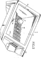
本発明のシステムは、全体に参照番号10を付した、小さいパッケージ済エレメント用の自動収容−分配装置である。この装置は、薬剤等の小パッケージエレメントを受け入れ、処理し、次いでこれらのエレメントをドラム型収容アッセンブリ14を含むシステムの大量収容部分内に移動するための入力ホッパとも呼ばれる入力容器12を含む。
The system of the present invention is an automatic containment-dispensing device for small packaged elements, generally designated by
個々のエレメントは、装置に導入された後、先ず最初に一個にされ、次いで装荷アッセンブリまで移動し、このアッセンブリで配向され、グリッパアッセンブリ16によって取り上げられ、ドラム型収容アッセンブリ14内の選択された位置に移動される。図示の実施例は、四つのドラム型収容アッセンブリを備えており、各アッセンブリは、個々にパッケージされたエレメントを収容するため、個々にアドレス可能/アクセス可能な複数のスロットがドラムの外側で開放した円筒体である。ドラム型収容アッセンブリ14は、図示の実施例では、個々のエレメントを収容装置内に移動するグリッパアッセンブリ16と同様に、コンピュータ制御で個々に回転できる。ドラム型収容装置の各スロットは、独特の方法で同定され、アクセスされる。
After the individual elements are introduced into the apparatus, they are first brought together, then moved to the loading assembly, oriented in this assembly, picked up by the
本システムは、更に、二つの取り出し機構18を含む。これらの機構は、図示の実施例では、夫々、二つの隣接したドラム型収容アッセンブリ間に配置されており、これらの機構の各々は、ドラム型収容アッセンブリの回転及び取り出し機構の垂直方向移動によって、これらの取り出し機構が作用する二つのドラム型収容アッセンブリの各隔室にアクセスできる。取り出し機構は、ドラム型収容アッセンブリのアクセスされた隔室内に収容されたエレメントをその開放した中央に向かって押すように作動するプッシャ部材を含む。取り出されたエレメントはドラムアッセンブリの開放中央領域を出口コンベア上に落下し、このコンベアによってシステムの外に、次の段階の装置上に移動される。この装置は、場合によっては、エレメント取り扱いコンベア22であってもよい。このコンベアは、エレメントを薬剤カート内に直接移動し、又は装荷装置に移動する。一杯になったカートは、病棟等で患者に渡す準備ができている。
The system further includes two
次に、添付図面を詳細に参照すると、装置10は、パッケージ済薬剤又は他のエレメントを郵便受けの扉と同様に単一の入口20を通して纏めて受け入れることができる。受け入れられた薬剤/エレメントには全ての種類の返却物が含まれる。装置は、エレメント/返却物を同定する、これを大量収容システムの収容位置に移動するように作動できる。システムは、更に、収容アッセンブリ内の選択されたエレメントを取り出すのが所望である場合、これらの選択されたエレメントにアクセスするように作動できる。
Referring now in detail to the accompanying drawings, the
これらの動作は、図示の実施例により、非常に迅速に、一分間に7回の作業で、確実に行うことができる。本システムの費用は、その大きな作動容量にも拘わらず、商業的に入手できる同様のシステムよりも遙かに低い。 According to the illustrated embodiment, these operations can be carried out very quickly and reliably in seven operations per minute. The cost of this system is much lower than similar commercially available systems, despite its large operating capacity.
入力ホッパ12と呼ばれる本発明のシステムの入力部分は、大きな湾曲した摺動自在の開口部20をその頂端に含む。これは図示の実施例では、長さが約40.64cm(約16インチ)で幅が約20.32cm(約8インチ)である。入力ホッパ12は、パッケージエレメントの大きさに応じて最大750個の個々のアイテムを取り扱うことができ、開口部20を通して一度に多数(250個)を受け入れることができる。
The input portion of the system of the present invention, called
本発明のシステムは、様々なエレメントを取り扱うことができる。薬剤は一つのカテゴリーであり、タブレットや錠剤及び液体エレメント等の経口薬剤並びに注射器等の医療用エレメントを含む。システムは、比較的小さい他のエレメントで使用することもできる。これには、様々なハードウェア部品、様々な種類の宝石類、及び場合によっては食品が含まれる。 The system of the present invention can handle various elements. Drugs are a category and include oral drugs such as tablets and tablets and liquid elements and medical elements such as syringes. The system can also be used with other elements that are relatively small. This includes various hardware parts, various types of jewelry, and in some cases food.
従って、本発明は、特定の種類のエレメントに限定されないが、薬剤型のエレメントに関して有用であることがわかった。
更に、入力は、特に、製造者から来た時点でパッケージ済の(又はパッケージされていない)個々のエレメントが入れられた特定の形体を持つ選択された大きさの箱に入れた、重ねてパッケージされたエレメントの形体であるのが望ましいが、本装置は、更に、エレメントを製造者から受け取ったままの状態で取り扱うことができるということは理解されるべきである。例えば、薬剤及び他のエレメントについて、これらの製造者の製品には、様々な固形薬剤用の様々な形体のブリスターパック及びポーチ、並びにバイアル、注射器、及びバルク薬剤が含まれる。ユークリッドパッケージ、並びにバルク液体の単位投与量を取り扱うための液体カップ、様々な大きさ及び構成のストリップパッケージ、及び製造者が提供する箱が含まれてもよい。様々な構成における本システムの柔軟性により、所望であれば、本システムを使用する病院等の施設は、重ねパッケージ(製造者から受け取った個々のエレメントを、パッケージ済エレメントであっても、新たなパッケージ/箱に入れたもの)、及び/又は再パッケージ(製造者から受け取った個々のエレメントを製造者のパッケージから取り出して新たなパッケージに入れる)を省略できる。
Thus, the present invention has been found useful with respect to drug-type elements, although not limited to a particular type of element.
In addition, the input is packaged in layers, especially in selected size boxes with specific features that contain individual elements that are packaged (or unpackaged) when they come from the manufacturer. Although it is desirable to be in the form of a modified element, it should be understood that the apparatus can further handle the element as received from the manufacturer. For example, for drugs and other elements, these manufacturers' products include various forms of blister packs and pouches for various solid drugs, as well as vials, syringes, and bulk drugs. Euclidean packages as well as liquid cups for handling bulk liquid unit doses, strip packages of various sizes and configurations, and boxes provided by the manufacturer may be included. Due to the flexibility of the system in various configurations, hospitals and other facilities that use the system can, if desired, place a stacked package (individual elements received from the manufacturer, even if the Package / box) and / or repackaging (removing individual elements received from the manufacturer from the manufacturer's package into a new package) can be omitted.
本システムを箱を使用して説明する。上文中に説明した変形例のパッケージは、図1の構造を幾らか変更することを必要とする。変形例の構造は、以下の適切な場所で論じられるであろう。 This system will be described using boxes. The variant package described above requires some modifications to the structure of FIG. Alternative structures will be discussed in the appropriate places below.
図示の実施例の入力ホッパ12は、幅が68.58cm(27インチ)、長さが53.34cm(21インチ)、及び深さが55.88cm(22インチ)の四角形のステンレス鋼製の箱27である。勿論、これらの寸法は変更してもよいけれども、本発明のシステムにはこの大きさが便利であり、上文中に説明したように約700個の小さなパッケージ済アイテムを収容する。これはかなりの数である。図示の実施例では、ホッパ28はステンレス鋼製であるが、この他の材料を使用してもよい。ホッパは、別の形体を備えていてもよい。
The
ホッパの二つの隣接した内壁30及び31は平らであり且つ垂直であるのに対し、他の二つの壁33及び34は、平らであるけれども、壁33の一部は下方に及び内方に約30°で延びており、壁34の一部は内方に約45°で延びている。壁33及び34の角度をなした部分は、各壁の頂縁部のところで又はその直ぐ下で開始する。
The two adjacent
ホッパ20の底部37からホッパの上縁部まで、箱44を上方に移動するための階段機構38が延びている。この機構38は、壁34の開口部40を通ってホッパ28の外に延びる。図示の実施例では、開口部40はほぼ正方形であり、約17.463cm(6・7/8インチ)×17.78cm(7インチ)である。階段機構38は一組の定置プレート42及び一組の可動プレート43を含み、各組は8枚の定置プレート及び8枚の垂直方向に配向された金属製プレートを含む。定置プレートは可動プレートと交互になっている。定置プレート42は固定されたままであるのに対し、これと交互になった可動プレート43をX方向及びY方向の両方向(前方及び上方)に移動する。空気圧シリンダ(図示せず)を使用し、可動プレート43をX方向及びY方向の両方向に駆動する。図示の実施例のプレート42及び43の各段の寸法は、約8.89cm(3・1/2インチ)(垂直方向)×16.51cm(6・1/2インチ)(水平方向)である。可動プレートは、図示の実施例では、移動サイクル毎にX方向(前方)に約75mm移動し、Y方向(上方)に50mm移動する。
A
図示の実施例では、定置プレート組及び可動プレート組の両方の各プレートの厚さは、約9.525mm(3/8インチ)である。図示の実施例では、各プレートには三つの階段が画成されている。階段の数は、特定の用途に応じてこれよりも多くてもよいし少なくてもよい。階段機構は、個々のカートン44を上方に移動し、ホッパ28から出す。
In the illustrated embodiment, the thickness of each plate of both the stationary plate set and the movable plate set is about 3/8 inch. In the illustrated embodiment, each plate is defined with three steps. The number of stairs may be more or less depending on the particular application. The stair mechanism moves the
図3のA乃至Eは、可動プレート43が定置プレート42に対してX方向及びY方向に移動するときの階段機構の順序を示す。上述のように、図示の実施例では、8枚の定置階段プレート42がホッパに亘って位置合わせして設けられている。8枚の可動階段プレート43が定置階段プレートと交互に配置されている。図3のA乃至Eは、三つの個々の階段を画成する3枚の定置プレート組及び可動プレート組を示す。画成される階段の数は変えることができる。更に、ホッパの実際の形体に応じて定置プレート及び可動プレートの実際の物理的寸法を変化させることができる。
3A to 3E show the order of the stair mechanism when the
図3のAは、可動階段プレート43をこれらのプレートの最下作動点で示す。順序の第1作動では、可動プレート43を上方に移動させる。この場合も、図示の実施例では、これは約50mmであり、これを順序の3Bに示す。図3のCでは、可動プレートを前方にX方向に約75mm移動する。この時点で、パッケージ(カートン)44はホッパの底部から階段機構の頂部まで持ち上げられている。図3のDでは、可動プレート43は下方に50mmの距離だけ移動した後、図3のEに示すように水平方向後方に開始位置まで移動する。
FIG. 3A shows the
階段機構38の実際の階段の数は、カバーされるべき距離に応じて変化させることができる。階段機構38は、個々のパッケージの分離を開始するための、及びこれらのパッケージをホッパの外に移動するための信頼性のある構成を提供する。しかしながら、このような結果をもたらすこの他のシステムを使用してもよい。
The actual number of steps of the
本明細書中に詳細に説明するシステムでは、医療用エレメントは全体が箱によって重ねてパッケージされている。しかしながら、システムを幾つか変更して他のパッケージング装置を使用してもよい。これを本発明の概念の範疇に対して簡単に説明する。例えば、箱の他に、上文中に論じたように、様々な大きさの袋、並びにカップ、ブリスターパック、ユークリッドパック、及び注射器を使用できる。 In the system described in detail herein, the medical elements are packaged entirely by boxes. However, other packaging devices may be used with some system modifications. This will be briefly described with respect to the concept of the present invention. For example, in addition to boxes, various sized bags and cups, blister packs, Euclidean packs, and syringes can be used as discussed above.
図4を参照すると、階段機構38はパッケージがこの機構の頂部に来るまで作動し、パッケージが機構の頂部に来たとき、階段を前方に移動することによってパッケージを一個化アッセンブリ構造の第1コンベア部分48上に投げ、このコンベアでパッケージは互いから長さ方向に分離する。一個化アッセンブリは、図示の実施例では、コンベアシステムと呼ばれる一連の連続したコンベアを含む。バッファコンベアとも呼ばれる第1コンベア48は、幅が約15.24cm(約6インチ)であり且つ長さが20.32cm(8インチ)であり、一連の空気式シリンダ(図示せず)によって毎秒25.4cm(10インチ)の速度で移動する。
Referring to FIG. 4, the
第1コンベア48に続き、増速ローラーと呼ばれる円筒形コンベア50が設けられている。増速ローラー50は、各パッケージが搬送システムの次の部分に一度に一つづつ進入するように、コンベア48上に存在する連続した各パッケージ間に隙間を形成するようになっている。増速ローラー50は、長さが15.24cm(6インチ)であり且つ直径が5.08cm(2インチ)であり、毎秒38.1cm(15インチ)の速度で移動する。増速ローラー50は、アイテムを一個化コンベア52に送る。
Following the
一個化コンベア52もまた幅が約15.24cm(約6インチ)であり且つ長さが20.32cm(8インチ)であり、特定の時期にコンピュータ制御で空気圧シリンダによって毎秒50.8cm(20インチ)で作動する。バッファコンベア48、増速ローラー50、及び一個化コンベア52は全て、基本的に同一平面内にあり、水平である。一個化コンベア52は、その末端に位置決めされた垂直コンベア54までアイテムを移動する。垂直コンベア54は、一個化コンベアの末端を横切って一個化コンベアの縁部56を越えて14.605cm(5・3/4インチ)延びる。垂直コンベア54は、図示の実施例では、高さが15.24cm(6インチ)であり且つ長さが約40.64cm(約16インチ)であり、特定の時期にコンピュータの制御下で毎秒25.4cm(10インチ)で作動する。
The
幅が約15.24cm(約6インチ)の一個化コンベア52の縁部56から、短い金属製固定傾斜板58が延びている。図示の実施例では、傾斜板58は長さが約17.78cm(約7インチ)であり且つ幅が8.573cm(3・3/8インチ)であり、下方への傾斜角度が約22°である。この角度は或る程度変化させることができるが、パッケージ済エレメントを、垂直コンベア54の作動の補助により、隣接した傾斜コンベア60上に滑り落とす上で便利であるように設計される。
A short metal fixed
パッケージ一個化プロセスでは、二つのアイテムが一個化コンベア52上に同時に移動した場合、これらの二つのアイテムは、通常は、垂直コンベア54の作動により、一個化コンベアから傾斜板58上への90°の方向変換により、分離される。傾斜コンベア60は、コンベア48及び52に対して180°方向に、即ち逆方向に移動する。傾斜コンベア60は幅が約15.24cm(約6インチ)であり且つ長さが40.64cm(約16インチ)であり、下方に好ましくは約10°の角度で、9°乃至11°の範囲内の角度で配向されている。垂直コンベア54は、傾斜コンベアの幅の約半分まで延びている。傾斜コンベア60は、その末端65に沿って設けられた短い壁64によって、及びその近縁部69の端部に沿った短い壁67によって境界付けられている。
In the package singulation process, if two items move simultaneously on the
角度をなしたプレート70が壁67から延びている。このプレートは、傾斜コンベア60の表面上を短い距離に亘って延びる。角度をなしたプレート70は、傾斜コンベア60から出るパッケージの移動を補助するが、搬送プロセスの作動には不必要である。アイテムは、傾斜コンベア60から主コンベア74上に移動する。この主コンベアは、この実施例では、傾斜コンベアに対して直角であり、システムの次の部分に続く。
An angled plate 70 extends from the
コンベア48、52、54、60、及び増速ローラー50の作動は、全体に図4に示すように配置された一連のセンサ(62−62(各コンベアに一つづつ設けられている)及びコンピュータ制御指令によって制御される。システムの各コンベアは、隣接した下流コンベアのセンサがそのコンベアにパッケージ/エレメントがないことを確認したときに上記速度で作動を開始する。例えば、増速ローラー50のセンサ62がこのローラーにパッケージが存在しないことを確認した場合、その前のコンベア即ちバッファコンベア48を作動し、その通常の速度で作動し、パッケージを増速ローラー50に移動する。このプロセスは、傾斜コンベア60まで下流に順次行われる。システムは、基本的には、待機列システムに基づき、即ち、一つのコンベアに空きがある場合、直前のコンベアを作動させる。これにより、パッケージは、バッファコンベア48上に移動されたときから一個化システムを通して制御下で移動される。箱が傾斜コンベア60に到達したとき、これらの箱は一個にされる。即ち、これらの箱は主コンベア74上に一つづつ移動される。
The operation of the
図示の実施例は、個々の箱を一つにする上で有効であり、注射器や均等なカップに関して有効である。しかしながら、ブリスターパック、ユークリッドパック、及び袋については、個々のユニットを取り出すための二軸線ガントリー真空取り出しシステムが有効である。 The illustrated embodiment is effective in bringing the individual boxes together and is effective with a syringe and an equivalent cup. However, for blister packs, Euclidean packs, and bags, a biaxial gantry vacuum removal system for removing individual units is useful.
パッケージは、主コンベア74上に移動したとき、先ず最初にコンベア上で計測され且つ配向される。主コンベアの縁部76に沿って、一個化壁78が設けられている。図示の実施例の一個化壁78は長さが24.13cm(9・1/2インチ)であり、高さが5.08cm(2インチ)である。シャットルアーム81を持つ一個化装置シャットルアッセンブリ80が傾斜コンベア60の側縁部65に沿って及び主コンベアと隣接した傾斜コンベア端部79に亘って位置決めされている。傾斜コンベア60の端部に亘って延びるシャットルアッセンブリの部分を整合バー区分83と呼ぶ。
When the package moves on the
作動に当たっては、パッケージ/アイテムが整合バー部分83を越えて主コンベア上に落下する。アイテムが主コンベア上に移動したとき、一個化装置シャットルアッセンブリ80を作動し、整合バー83を主コンベア74に亘って掃くように移動する。主コンベアが連続的に作動するため、アイテムは、整合バー83がアイテムを主コンベアに亘って移動するとき、主コンベア上で更に前方に移動され、一個化壁78と接触する。別の態様では、コンベア74は、連続的に搬送するのでなく、選択された時期に搬送を中断するように制御することができる。搬送を中断することは、袋やブリスターパック及びユークリッドパック等の特定の種類のパッケージについては更に効果的である。
In operation, the package / item drops over the
アイテムの前方への移動は一個化装置出口ゲート84によって停止される。このゲートは主コンベアに亘って延びるが、僅かな距離だけ主コンベアの上方に設けられており、これにより主コンベアは何ら干渉を受けることなく作動する。個々のアイテムは、かくして、整合バー83の作用及び前方へ移動する主コンベアにより、一個化壁及び一個化装置出口ゲートに対して配向される。
The forward movement of the item is stopped by the
一個化装置シャットルシステム80は、シャットルアーム81と隣接した延長アームの端部に設けられた電位差計85を含む。この電位差計は空気圧シリンダ87によって制御される。電位差計は、一個化装置シャットルアッセンブリの作用によって壁78に押し付けられたアイテムまで延びる。電位差計は、アイテムとの接触により読み(電位差計の延長距離で決まる)を発生し、次いでこの読みを許容可能な大きさを含む参照表と比較する。パッケージに対する損傷等の何らかの理由により物品の大きさが許容差を外れた場合には、一個化壁78を持ち上げ、整合バー83を更に移動することによりアイテムを一個化装置排除ビン86に押し込む。
The unitized
アイテムがコンベア74上で壁78に対して移動するとき、センサ89がアイテムの高さを計測する。アイテムが高過ぎる場合には、主コンベアの末端76のところで一個化壁78に配置された一個化チッパーピン88を作動させ、水平方向外方に主コンベアを横切って移動し、立ったアイテムをコンベア上に倒す。シャットルアッセンブリを使用し、アイテムをコンベア上で再度整合させる。図示の実施例では、ピン88は長さが約5.72cm(約2・1/4インチ)であり、主コンベア74の表面の上方約3.81cm(約1・1/2インチ)のところに配置されている。
As the item moves relative to the
以上説明した実施例におけるコンベア上でのアイテムの同定及び配向/位置合わせは、基本的には、機械的/電気的手段によって行われる。こうした手段には、一個化装置シャットルゲート及び延長電位差計アッセンブリを使用することが含まれ、アイテムを一個化構造に対して連続的に位置決めする。しかしながら、アイテムを同定しアイテムを確実に特定の標準に適合させ、適切に整合/位置合わせするために他の装置を使用してもよい。このような変形例の一つは、アイテムを撮像するカメラを含む視覚的センサシステムである。アイテムを完全に同定し、大きさを含む特定の標準と確実に合致させるため、周知の画像加工技術を使用できる。大きさを確認するためにアイテムの表面の各々と接触する延長フィンガ型システム等の他の機械的装置を使用することもできる。センサ装置は、袋、ブリスターパック、及びユークリッドパックに特に適している。 The identification and orientation / alignment of items on the conveyor in the embodiment described above is basically performed by mechanical / electrical means. Such means include the use of a monolithic device shuttle gate and an extended potentiometer assembly to continuously position items relative to the monolithic structure. However, other devices may be used to identify the item and ensure that the item conforms to a particular standard and is properly aligned / aligned. One such variation is a visual sensor system that includes a camera that images an item. Well known image processing techniques can be used to fully identify the item and ensure that it meets certain standards, including size. Other mechanical devices such as an extended finger type system that contacts each of the item's surfaces to confirm size can also be used. The sensor device is particularly suitable for bags, blister packs and Euclidean packs.
一個化装置出口ゲート84の直ぐ下流にバーコード走査システム94が設けられている(図8参照)。バーコード走査システム94は、主コンベア74の上方に位置決めされたフレーム97に取り付けられた四つのバーコード読み取り機96−96を含む。これらの四つのバーコード読み取り機はアイテムの四つの側部に設けられたバーコードを読み取る。これらのバーコード読み取り機は、更に、上面も見ることができる。アイテムの底面(コンベアと接触した表面)はバーコードシステム94によって走査されない。底面は、以下に更に詳細に説明するように、本発明の下流部分で底面の走査が行われる。バーコードは、バーコード走査システム94によって認識されたとき、システムの制御部分に伝達される。
A
パッケージ/アイテムは、バーコード走査システム94の下を通過した後、主コンベア74によってディポットステージングゲート100まで搬送される。図示の実施例では、連続的に作動する主コンベアは幅が約15.24cm(約6インチ)であり且つ長さが139.7cm(55インチ)であり、毎秒約25.4cm(約10インチ)で作動する。ディポットステージングゲート100は、一個化装置出口ゲート84の前方約33.02cm(約13インチ)の距離のところに配置されている。主コンベア74は、傾斜コンベアからシステムの出口の近くまで延びている。
After the package / item passes under the
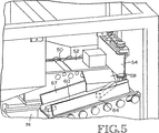
ディポットステージングゲートの下流のシステムの次の部分は、図9乃至図11に示す装荷プラットホームアッセンブリである。装荷プラットホームアッセンブリの全体に参照番号101が付してある。ディポットステージングゲートによって停止されたアイテムがある場合には、先ず最初に、水平方向装荷プラットホーム110が「空」であるかどうか、即ち装荷プラットホーム上にアイテムが存在しないかどうかを装荷プラットホームセンサ(図示せず)が確認する。装荷プラットホーム110が空である場合、ディポットステージングゲート100を持ち上げてアイテムを主コンベアによってディポット停止ゲート104まで移動する。このゲート104は、装荷プラットホームの末端のところで主コンベア74を横切って延びる。移送シャットルアーム106が主コンベアに沿って装荷プラットホームから約19.05cm(約7・1/2インチ)に亘って延びている。アイテムがディポット停止ゲート104によって停止された後、移送シャットル106を作動し、アイテムと接触させる。電位差計107及びエアシリンダ109を使用し、箱/アイテムを再度計測する。レーザー111を使用し、箱の縁部を見つける。箱は、装荷プラットホームアッセンブリのプラットホーム部分110に押し付けられる。図示の実施例では、プラットホーム110はアクリルプラスチック製であり、15.24cm×8.89cm(6インチ×1.1/2インチ)の寸法を有する。
The next part of the system downstream of the depot staging gate is the loading platform assembly shown in FIGS. The entire loading platform assembly is denoted by
プラットホーム110の下には、プレート110とほぼ同じ外部寸法を持つリフトプレート112が配置されている。リフトプレート112には複数のピン113が設けられている(図9参照)。これらのピンは、リフトプラットホームの上面に取り付けられており、そこから上方に延びている。ピンの高さは、図示の実施例では、約10mmである。プラットホーム110には複数の貫通開口部が設けられており、これらの開口部はリフトプレート112のピン113と位置合わせされている。リフトプレート112は、プラットホームを上下に移動する空気式アクチュエータ(図示せず)によって制御される。リフトプレート112がその最下位置にあるとき、装荷プラットホーム110の上面は平らであり、主コンベア表面と同一平面内にあり(図11参照)、アイテムを主コンベアからプラットホーム110に直接的に押し付けることができる。
A
リフトプラットホーム112がその持ち上げ位置(図9及び図10参照)にあるとき、ピン113は装荷プラットホームを通って上方に、装荷プラットホーム110の上面の上方約5mm乃至7mmまで延びる。ピン113は、アイテムをプラットホーム上に信頼性を以て支持できるように、及びアイテムをプラットホーム110の表面の上方に持ち上げることができるように配置される。これにより、以下に更に詳細に説明するグリッパ機構によって、アイテムを最初に把持するための空間を提供する。
When the
上述のように、主コンベア74はアイテムをディポット停止ゲート104まで、連続した移動又は断続した(停止及び開始を含む)移動のいずれかによって下方に移動する。アイテムがディポット停止ゲートでセンサ(図示せず)によって検出されたとき、移送シャットルアーム106が作動され、主コンベア74に亘って移動し、ディポット停止ゲート104に当接した待機列をなしたアイテムをプラットホーム110に押し付ける。バーコードがアイテムについて予め検出されなかった場合、即ちバーコードが底面上にある場合、リフトプラットホーム112は、先ず最初に、行路の外に移送し、その下に位置決めされた従来の走査ヘッド118によってアイテムの底面を読み取ることができるようにする。バーコードが認識されると、これをシステム制御装置と位置合わせし、作動順序を継続する。バーコードが認識されなかった場合には、空気式シリンダ121によって作動される移送バー119によってアイテムをプラットホーム110から取り除き、これによりアイテムを主コンベア上に戻す。次いで、主コンベア74がアイテムをディポット停止ゲート104に対して移動し、このゲートが持ち上がり、次いでアイテムを取り出し傾斜部120が設けられた主コンベアの末端まで移動し、アイテムは取り出し傾斜部を下方に摺動し、アイテムを第2取り出し箱122に入れる。
As described above, the
バーコードが予め認識されて位置合わせされた場合又は装荷プラットホームアッセンブリのバーコード走査装置118によってバーコードが認識された場合には、リフトプラットホーム112を移送してその元の位置に戻す。ドラム型収容エレメント14−14の一つに設けられたスロットの数は、この時点で、システム制御装置によってエレメントに割当てられる。上述のように、リフトプラットホーム112を作動し、このプラットホームがその持ち上げ位置にあるとき、ピン113は装荷プラットホーム110を通って延び、アイテムを持ち上げて装荷プラットホームの表面から離す。ピン113がプラットホーム110を通って延びてアイテムを持ち上げた後、移送シャットル106及びディポット停止ゲート104の両方を引っ込め、把持−収容アッセンブリを所定位置に置くことができるようにし、向き合った把持エレメント148によってアイテムを掴むことができるようにする。
If the bar code has been previously recognized and aligned, or if the bar code has been recognized by the bar code scanning device 118 of the loading platform assembly, the
図9、図10、及び図13、図14は、本発明の把持−収容アッセンブリを示す。図1に関して上文中に説明したように、本発明は、四つのドラム型収容アッセンブリ14−14用の単一の把持−収容アッセンブリを含む。各ドラム型収容アッセンブリは、複数の個々の水平方向スロットを含む。これらのスロットは、その前端及び後端の両方が開放している。各ドラム型収容アッセンブリは、中央が開放した円筒体形状である。この円筒体は、垂直方向に順次積み重ねられた複数のリング部分(棚)を含み、これらのリング部分は垂直壁によって分離される。リング及び壁は個々のスロットを画成する。リングと壁との間の間隔は、様々な大きさ及び形体の収容スロットを画成するために変化させることができる。図示の実施例では、四つの異なる大きさのスロットが図示してある。収容スロットの構成、大きさ、及び形体は、収容されるべきエレメント及び特定のエレメントの大きさに合わせて変化させることができる。例えば、個々のスロットは、収容されるべき特定のパッケージ、例えば、とりわけ、袋、箱、パック、又は注射器に応じて大きさが変わる。 9, 10 and 13, 14 show the grip-accommodation assembly of the present invention. As described above with respect to FIG. 1, the present invention includes a single gripping-receiving assembly for four drum-type receiving assemblies 14-14. Each drum-type receiving assembly includes a plurality of individual horizontal slots. These slots are open at both the front and rear ends. Each drum-type receiving assembly has a cylindrical shape with an open center. The cylinder includes a plurality of ring portions (shelves) that are sequentially stacked in the vertical direction, and these ring portions are separated by vertical walls. Rings and walls define individual slots. The spacing between the ring and the wall can be varied to define receiving slots of various sizes and configurations. In the illustrated embodiment, four different sized slots are shown. The configuration, size and shape of the receiving slot can be varied to accommodate the element to be received and the size of the particular element. For example, the individual slots vary in size depending on the particular package to be accommodated, for example, among other things, a bag, box, pack, or syringe.
箱について図示した実施例では、ドラム型収容装置14の外径は約48.26cm(約19インチ)であるのに対し、内径は約35.56cm(約14インチ)である。図示の実施例では、各ドラム型収容アッセンブリは金属又は同様の剛性材料で形成されている。各ドラム型収容アッセンブリは、モータ120、及び各ドラムの下端に設けられたプーリ(図示せず)に掛けたベルト駆動装置によって回転させることができる。図示の実施例では、モータ120は、把持−収容アッセンブリがドラムの各収容スロットにアクセスできるように各ドラム型収容アッセンブリの正確な回転位置を制御できるサーボモータである。
In the illustrated embodiment for the box, the outer diameter of the drum-
図12及び図13を参照すると、把持−収容アッセンブリは、ほぼ各ドラム型収容アッセンブリ14の高さまで延びる細長いタワーエレメント130を含む。把持−収容アッセンブリは、ギヤボックス134を介して下プーリ(図示せず)を駆動するサーボモータ132を含む。これらは全てタワー130のベースに配置されている。駆動ベルトがベースプーリからタワーを通って上方に、タワーの頂部に配置された上プーリ(図示せず)の周囲に延びている。プーリ136及び137を釣合い重りとともに使用する。釣合い重りは、グリッパ支持アッセンブリ139の移動の制御を補助する。
With reference to FIGS. 12 and 13, the gripping-receiving assembly includes an
グリッパ支持アッセンブリ139は、タワー130から水平方向外方に延びる支持アーム140を含む。アーム140から取り付けプレート142が延びている。取り付けプレート142には把持エレメントアッセンブリ143が回転自在に連結されている。把持エレメントアッセンブリ143は、取り付けプレート142の上面に位置決めされたベルト駆動式プーリ144を含む。ベルト145は、把持エレメントアッセンブリを回転方向にサーボモータ146によって移動できる。
The
把持エレメントアッセンブリは、更に、プレート142の下に配置された二つの向き合った把持アーム148を含む。これらのアームは垂直位置をとり、狭幅の耳部151をその下端に備えている。これらの二つの狭幅の耳部151−151は互いに向かって延びている。把持アーム148は、参照番号150を付したモータ/ベルト装置の制御により互いに近づいたり離れたり移動する。モータ/ベルト装置150の作動により、把持アーム148は、最初に、互いから離れるように移動でき、これにより耳部151−151を装荷プレート上の箱/アイテムの下に位置決めでき、次いで互いに向かって移動でき、アイテムをしっかりと掴む。プレート142の下面には、モータ154又はエアシリンダによって制御される線型アクチュエータ152が取り付けられている。この線型アクチュエータ152は、把持エレメントアッセンブリとともに軸線方向前後に移動する。
The gripping element assembly further includes two opposed gripping
把持エレメントアッセンブリは、更に、空気式アクチュエータによって制御されるプッシャアーム156を含む。プッシャアームは、把持アーム148間に配置されており、作動に当たって前方に移動し、把持アーム148によって保持されたアイテムに当たる。プッシャアーム156の自由端にはプッシュピンエレメント158が位置決めされている。プッシュピン158は、作動時に、プッシャアーム156の端部を越えて外に延び、ドラム型収容装置14の正しく割り当てられた隔室内にアイテムを移動するための最終的な力を提供する。
The gripping element assembly further includes a pusher arm 156 that is controlled by a pneumatic actuator. The pusher arm is disposed between the gripping
作動では、把持−収容アッセンブリは4度の自由度を有する。グリッパ支持アッセンブリは、サーボモータ/ギヤボックス/ベルト/プーリ/釣合い重り構成によってタワー130を上下に(垂直方向に)移動する。グリッパ支持アッセンブリについてのバランスは、上下に移動する釣合い重りによって提供され、これによりグリッパ支持アッセンブリに対する制御を改善できる。把持アーム148は、各パッケージ/アイテムを掴んだり放したりするため、モータ及びベルト構成151によって互いに近づいたり離れたり移動する。把持エレメントアッセンブリは、モータ、ベルト、及びプーリ構成によって回転させることができ、モータ154の作用によって線型アクチュエータ152に沿って軸線方向に移動させることができる。最後に、プッシャアーム及び延長ピン構成がアイテムを把持アーム148からドラム型収容装置14の選択された収容スロット内に移動する。
In operation, the gripping-accommodating assembly has 4 degrees of freedom. The gripper support assembly moves the
図示し且つ説明した把持−収容アッセンブリは、特に重ねてパッケージした薬剤の用途について、又は箱に入れた他のエレメントについて好ましいけれども、他の掴みシステムを使用してもよいということは理解されるべきである。例えば、真空ヘッド部分が装荷プラットホーム上のアイテムと接触し、アイテムを真空(吸引力)の作用で持ち上げる低プロファイルの真空チャックシステムが別の可能性である。このような実施例では持ち上げピンは不要である。同様のシステムが他の用途で周知である。パッケージ又はアイテム自体の一部が磁性を帯びた、磁気等の他の構成を使用することもできる。ロボットフィンガシステムが別の変形例である。薬剤又は他のアイテムをコンベア又は装荷プラットホームから取り出してこれらを収容装置の割当てられた位置に置くための様々な方法及び機構がある。 It should be understood that the gripping-accommodating assembly shown and described is particularly preferred for over-packaged drug applications or other elements in a box, although other gripping systems may be used. It is. For example, another possibility is a low profile vacuum chuck system where the vacuum head portion contacts an item on the loading platform and lifts the item under the action of a vacuum (suction force). In such an embodiment, no lifting pin is required. Similar systems are well known for other applications. Other configurations, such as magnetism, where a portion of the package or item itself is magnetic can also be used. A robot finger system is another variation. There are various methods and mechanisms for removing medications or other items from a conveyor or loading platform and placing them in assigned locations on the containment device.
本発明のシステムは、図14に詳細に示す二つの取り出しアッセンブリ18を更に含む。これらの取り出しアッセンブリは、システムの両縁部近くに、二つの隣接したドラム型収容エレメント間に配置されている。図示の実施例の各取り出しアッセンブリは、二つのドラム型収容ユニットに対して作用する。しかしながら、これを代えてもよい。各取り出しアッセンブリ18はタワー162を含み、このタワーには、サーボモータ164及びプーリシステム166によって駆動されるベルト163が取り付けられている。各取り出しアッセンブリは二つの取り出しユニット168及び170を含み、各取り出しユニットは二つの固定取り出しアーム172を有し、これらのアームは、図示の実施例では、互いに対して30°の角度で配置されている。取り出しユニット168及び170は、タワーの全高に亘って上下に移動し、ユニット170はタワーの上部分をカバーし、ユニット168は残りの部分をカバーする。
The system of the present invention further includes two
各アームの端部には、取り出されるべき所望のアイテムがドラム型収容アッセンブリの選択されたスロットに存在することを確認するセンサ173が設けられている。そうでない場合には、制御システムに在庫管理エラーが記録される。アイテムが存在する場合には、指令が提供され、取り出しシリンダがアーム172を延ばし、このアームがアイテムを取り出しアッセンブリからドラム型収容装置の中央に押し込み、ここで出力コンベア174に落下する。単一の取り出しアッセンブリが作用する図示の実施例のドラム型収容アッセンブリの各対の下に、アイテムをシステムの外に搬送するための出力コンベアが設けられている。アーム172に設けられた取り出しセンサ173は、選択されたアイテムが取り出されたことを認識する。次いで、取り出しシリンダを引っ込める。
At the end of each arm is a
作動では、選択されたアイテムを装置から取り出すため、先ず最初に、取り出されるべきアイテムを収容したドラム型収容装置の隔室が取り出しアッセンブリの取り出しアームと一直線上に並ぶようにドラム型収容アッセンブリを回転する。次いで取り出しシリンダを作動し、アイテムをドラム型収容装置の中央に押し込む。下方にあるコンベアを作動させ、放出されたアイテムをシステムから容器に、又は恐らくは別のコンベア(図1で参照番号22を付したコンベア)上に移動し、これによりアイテムを薬剤カートに入れるといった処理を更に行うために別の位置にアイテムを移動する。 In operation, in order to remove a selected item from the device, the drum-type receiving assembly is first rotated so that the compartment of the drum-type receiving device containing the item to be removed is aligned with the pick-up arm of the pick-up assembly. To do. The take-off cylinder is then actuated to push the item into the center of the drum-type storage device. A process that activates the lower conveyor and moves the released items from the system to containers, or perhaps onto another conveyor (conveyor labeled with reference numeral 22 in FIG. 1), thereby placing the items in a drug cart. Move the item to another location for further processing.
取り出しアームを含む図14の電気機械的構成に対する変形例は、収容されたアイテムを空気圧で取り出すエアノズル構成である。エアノズル構成は、袋、ブリスターパック、及びユークリッドパックに関して特に有効である。 A variation on the electromechanical arrangement of FIG. 14 that includes a take-out arm is an air nozzle arrangement that takes out the contained items pneumatically. The air nozzle configuration is particularly effective for bags, blister packs, and Euclidean packs.
従って、返却された薬剤を含む束をなした薬剤等のアイテムを受け取り、これらのアイテムを一個にし、次いでこれらのアイテムが許容差内にあることを同定し確認する性能を持つシステムを説明した。次いで、図示の実施例では、アイテムをコンベア上で配向した後、装荷プラットホームに移動し、このプラットホームでグリッパ−収容アッセンブリ又は真空装置がアイテムをバルク収容ユニット内に移動する。かくして、返却物を含む薬剤又は他のエレメントを同時に収容でき、指令がなされたときにこれらのアイテムを装置から容器又はコンベアに出すことを同じシステムで行うことができる。 Thus, a system has been described that has the ability to receive items such as a bundle of medications that contain returned medication, combine these items, and then identify and confirm that these items are within tolerance. In the illustrated embodiment, the items are then oriented on a conveyor and then moved to a loading platform, where a gripper-receiving assembly or vacuum device moves the items into the bulk receiving unit. Thus, medications or other elements, including returned items, can be accommodated simultaneously, and these items can be removed from the device to a container or conveyor in the same system when commanded.
本発明の好ましい実施例を例示の目的で説明したけれども、特許請求の範囲に定義された本発明の精神から逸脱することなく、上文中に説明した変形例の他に変更及び入替えを行うことができるということは理解されるべきである。 While the preferred embodiment of the invention has been described by way of example, modifications and substitutions may be made in addition to the variations described above without departing from the spirit of the invention as defined in the claims. It should be understood that it can.
10 自動収容−分配装置
12 入力ホッパ
14 ドラム型収容アッセンブリ
16 グリッパアッセンブリ
18 取り出し機構
20 入口
22 エレメント取り扱いコンベア
DESCRIPTION OF
Claims (2)
複数の個々のエレメントを一時的に収容するためのビン、
個々のエレメントを一個化するための装置であって、作動に当たり、エレメントを前記システム内の装荷機構に移動するシステムコンベアにこれらのエレメントを一つづつ載せるための装置、
エレメントをコンベアから取り出し、いつでも収容できるようにエレメントを位置決めするための装荷機構、
前記エレメントを収容するための個々にアドレス可能な複数の収容位置を含む大量収容装置、
位置決めされたエレメントを個々に次々に移動し、各エレメントを前記大量収容装置の予め選択された位置に収容するためのアッセンブリ、及び
選択された個々のエレメントを前記大量収容装置の周知の位置から取り出し、分配されたエレメントをシステムの外に移動するための少なくとも一つの分配アッセンブリを含む、システム。In a system for automatically containing and distributing individual elements,
A bin for temporarily accommodating a plurality of individual elements,
An apparatus for unifying the individual elements, the apparatus for placing the elements one by one on a system conveyor which, in operation, moves the elements to a loading mechanism in the system ;
A loading mechanism to position the element so that it can be removed from the conveyor and stored at any time;
A mass storage device including a plurality of individually addressable storage locations for storing the elements;
An assembly for moving the positioned elements individually one after the other and receiving each element in a preselected position of the mass storage device, and removing the selected individual element from a known position of the mass storage device A system comprising at least one dispensing assembly for moving the dispensed element out of the system.
Applications Claiming Priority (2)
| Application Number | Priority Date | Filing Date | Title |
|---|---|---|---|
| US10/232,560 US7100792B2 (en) | 2002-08-30 | 2002-08-30 | Automatic apparatus for storing and dispensing packaged medication and other small elements |
| PCT/US2003/026614 WO2004020294A2 (en) | 2002-08-30 | 2003-08-26 | Apparatus for storing and dispensing packaged medication |
Publications (3)
| Publication Number | Publication Date |
|---|---|
| JP2005537200A JP2005537200A (en) | 2005-12-08 |
| JP2005537200A5 JP2005537200A5 (en) | 2010-04-30 |
| JP4664676B2 true JP4664676B2 (en) | 2011-04-06 |
Family
ID=31977036
Family Applications (1)
| Application Number | Title | Priority Date | Filing Date |
|---|---|---|---|
| JP2004532991A Expired - Lifetime JP4664676B2 (en) | 2002-08-30 | 2003-08-26 | System for automatically containing and distributing individual elements |
Country Status (9)
| Country | Link |
|---|---|
| US (3) | US7100792B2 (en) |
| EP (1) | EP1545983B1 (en) |
| JP (1) | JP4664676B2 (en) |
| AT (1) | ATE475596T1 (en) |
| AU (1) | AU2003268181C1 (en) |
| CA (1) | CA2496614C (en) |
| DE (1) | DE60333574D1 (en) |
| ES (1) | ES2348521T3 (en) |
| WO (1) | WO2004020294A2 (en) |
Families Citing this family (130)
| Publication number | Priority date | Publication date | Assignee | Title |
|---|---|---|---|---|
| US6847861B2 (en) | 2001-11-30 | 2005-01-25 | Mckesson Automation, Inc. | Carousel product for use in integrated restocking and dispensing system |
| US20040133705A1 (en) * | 2002-08-09 | 2004-07-08 | Brian Broussard | Controller for dispensing products |
| US7228198B2 (en) | 2002-08-09 | 2007-06-05 | Mckesson Automation Systems, Inc. | Prescription filling apparatus implementing a pick and place method |
| US7100792B2 (en) * | 2002-08-30 | 2006-09-05 | Omnicell, Inc. | Automatic apparatus for storing and dispensing packaged medication and other small elements |
| CA2452207A1 (en) * | 2002-12-06 | 2004-06-06 | Robert B. Meek, Jr | Inventory management and replenishment system |
| US7052097B2 (en) | 2002-12-06 | 2006-05-30 | Mckesson Automation, Inc. | High capacity drawer with mechanical indicator for a dispensing device |
| US8195328B2 (en) | 2003-09-19 | 2012-06-05 | Vesta Medical, Llc | Combination disposal and dispensing apparatus and method |
| WO2005055116A2 (en) | 2003-11-26 | 2005-06-16 | Mckesson Automation Inc. | Integrated suite of medical tools |
| US9706857B2 (en) | 2004-02-03 | 2017-07-18 | Rtc Industries, Inc. | Product securement and management system |
| US9375100B2 (en) | 2004-02-03 | 2016-06-28 | Rtc Industries, Inc. | Product securement and management system |
| US8047385B2 (en) | 2004-02-03 | 2011-11-01 | Rtc Industries, Inc. | Product securement and management system |
| US8235222B2 (en) | 2004-02-03 | 2012-08-07 | Rtc Industries, Inc. | Product securement and management system |
| US8113601B2 (en) | 2004-02-03 | 2012-02-14 | Rtc Industries, Inc. | Product securement and management system |
| US11375826B2 (en) | 2004-02-03 | 2022-07-05 | Rtc Industries, Inc. | Product securement and management system |
| US20050171813A1 (en) * | 2004-02-04 | 2005-08-04 | Jordan Mchael L. | System for identifying and sorting orders |
| US7395897B2 (en) * | 2004-04-09 | 2008-07-08 | Vecta Oil & Gas, Ltd. | Accelerated weight drop configurable for use as a shear wave seismic energy source and a method of operation thereof |
| US8041453B2 (en) * | 2004-09-27 | 2011-10-18 | Walker Digital, Llc | Method and apparatus for defining and utilizing product location in a vending machine |
| US7146247B2 (en) * | 2004-11-24 | 2006-12-05 | Cerner Innovation, Inc. | Computerized method and system for loading and/or unloading a tray using laser scanning technology |
| US7177721B2 (en) * | 2004-11-24 | 2007-02-13 | Cerner Innovation, Inc. | Computerized method and system for loading and/or unloading a tray having a light grid over a surface thereof |
| EP1839223A2 (en) * | 2004-12-03 | 2007-10-03 | Mckesson Automation Inc. | Mobile point of care system and associated method and computer program product |
| US7783383B2 (en) | 2004-12-22 | 2010-08-24 | Intelligent Hospital Systems Ltd. | Automated pharmacy admixture system (APAS) |
| US7828158B2 (en) * | 2005-07-14 | 2010-11-09 | Displays Plus, Inc. | Merchandise dispensing apparatus providing theft deterrence |
| US7931859B2 (en) | 2005-12-22 | 2011-04-26 | Intelligent Hospital Systems Ltd. | Ultraviolet sanitization in pharmacy environments |
| US7673772B2 (en) * | 2006-02-10 | 2010-03-09 | Cerner Innovation, Inc. | Method for dispensing medications |
| US7673771B2 (en) * | 2006-02-10 | 2010-03-09 | Cerner Innovation, Inc. | Apparatus for dispensing medications |
| US8036773B2 (en) * | 2006-05-10 | 2011-10-11 | Mckesson Automation Inc. | System, method and corresponding apparatus for storing, retrieving and delivering unit dose blisters |
| US20080033596A1 (en) * | 2006-07-06 | 2008-02-07 | Fausak Andrew T | Vision Feedback Detection for Vending Machines and the Like |
| CA2668981C (en) * | 2006-11-09 | 2016-10-04 | Intelligent Hospital Systems Ltd. | Control of fluid transfer operations |
| KR100800285B1 (en) * | 2006-11-20 | 2008-02-01 | (주)제이브이엠 | System for managing pharmaceuticals and method therefor |
| US7974728B2 (en) * | 2007-05-04 | 2011-07-05 | Taiwan Semiconductor Manufacturing Company, Ltd. | System for extraction of key process parameters from fault detection classification to enable wafer prediction |
| US8009913B2 (en) * | 2007-05-29 | 2011-08-30 | Mckesson Automation, Inc. | System, method, apparatus and computer program product for capturing human-readable text displayed on a unit dose package |
| US8738383B2 (en) | 2007-06-07 | 2014-05-27 | Aesynt Incorporated | Remotely and interactively controlling semi-automatic devices |
| US8280550B2 (en) * | 2008-06-17 | 2012-10-02 | Omnicell, Inc. | Cabinet with remote integration |
| US8140186B2 (en) * | 2007-06-19 | 2012-03-20 | Omnicell, Inc. | Bin allocation systems, methods, and devices |
| US8271138B2 (en) | 2007-09-12 | 2012-09-18 | Intelligent Hospital Systems Ltd. | Gripper device |
| US8215543B2 (en) * | 2007-09-21 | 2012-07-10 | Omnicare, Inc. | Methods for filling prescriptions to fulfill a customer order |
| CA2700373C (en) * | 2007-09-21 | 2016-05-24 | Omnicare Inc. | Automated label verify systems and methods for dispensing pharmaceuticals |
| DE202007018436U1 (en) * | 2007-09-25 | 2008-07-24 | Kht Kommissionier- Und Handhabungstechnik Gmbh | System for decoupled storage and system for optimized use of a picking device |
| US8225824B2 (en) * | 2007-11-16 | 2012-07-24 | Intelligent Hospital Systems, Ltd. | Method and apparatus for automated fluid transfer operations |
| US20090169138A1 (en) * | 2007-12-28 | 2009-07-02 | Mckesson Automation Inc. | Medication and medical supply storage package and method |
| US8094028B2 (en) * | 2007-12-28 | 2012-01-10 | Mckesson Automation, Inc. | Radio frequency alignment object, carriage and associated method of storing a product associated therewith |
| US8006903B2 (en) * | 2007-12-28 | 2011-08-30 | Mckesson Automation, Inc. | Proximity-based inventory management system using RFID tags to aid in dispensing and restocking inventory |
| CA2629916A1 (en) * | 2008-01-23 | 2009-07-23 | Jvm Co., Ltd. | Apparatus and method for automatically packing prescription packages and prescription package box |
| US20090194987A1 (en) * | 2008-01-31 | 2009-08-06 | Mckesson Automation Inc. | Method, apparatus and medication storage device for efficiently generating medication labels |
| DE202008001683U1 (en) * | 2008-02-06 | 2008-07-03 | Beils, Dirk Rolf | Automated storage device for a pharmacy warehouse |
| KR101006014B1 (en) * | 2008-08-21 | 2011-01-06 | (주)제이브이엠 | Automatic medicine packing machine with hopper cleaning device |
| US10916340B2 (en) * | 2008-12-05 | 2021-02-09 | Remedi Technology Holdings, Llc | System and methodology for filling prescriptions |
| US9938082B2 (en) * | 2008-12-05 | 2018-04-10 | Remedi Technology Holdings, Llc | Pharmaceutical dispensing system and associated method |
| US7982612B2 (en) | 2009-02-20 | 2011-07-19 | Mckesson Automation Inc. | Methods, apparatuses, and computer program products for monitoring a volume of fluid in a flexible fluid bag |
| US9149405B2 (en) | 2009-03-03 | 2015-10-06 | Aesynt Incorporated | Medication storage and dispensing unit having a vial dispenser |
| US8929641B2 (en) * | 2009-03-17 | 2015-01-06 | Aesynt Incorporated | System and method for determining the orientation of a unit dose package |
| US8386070B2 (en) | 2009-03-18 | 2013-02-26 | Intelligent Hospital Systems, Ltd | Automated pharmacy admixture system |
| US8405875B2 (en) * | 2009-03-23 | 2013-03-26 | Mckesson Automation Inc. | Visibly-coded medication label and associated method, apparatus and computer program product for providing same |
| US20100249997A1 (en) * | 2009-03-25 | 2010-09-30 | Greyshock Shawn T | System, method and corresponding apparatus for detecting perforations on a unit dose blister card |
| US8400277B2 (en) | 2009-03-30 | 2013-03-19 | Mckesson Automation Inc. | Methods, apparatuses, and computer program products for monitoring a transfer of fluid between a syringe and a fluid reservoir |
| US20100263947A1 (en) * | 2009-04-20 | 2010-10-21 | Chris John Reichart | Method for generating electricity from solar panels for an electrical system inside a truck/semi/vehicle |
| KR101620353B1 (en) * | 2009-05-29 | 2016-05-12 | (주)제이브이엠 | tool of the robot in the automatic medication control system |
| EP2256703B1 (en) * | 2009-05-29 | 2015-07-15 | JVM Co., Ltd. | Automated medicine storage and medicine introduction/discharge management system |
| US8644982B2 (en) * | 2009-09-30 | 2014-02-04 | Mckesson Automation Inc. | Unit dose packaging and associated robotic dispensing system and method |
| US8869667B2 (en) | 2009-12-04 | 2014-10-28 | Aesynt Incorporated | System, method and corresponding apparatus for singulating a unit dose blister card |
| US20110161108A1 (en) * | 2009-12-30 | 2011-06-30 | Mckesson Automation Inc. | Systems and methods for detecting diversion in drug dispensing |
| US8640586B2 (en) * | 2010-03-23 | 2014-02-04 | Mckesson Automation Inc. | Method and apparatus for facilitating cutting of a unit dose blister card |
| US8453548B2 (en) | 2010-03-23 | 2013-06-04 | Mckesson Automation Inc. | Apparatuses for cutting a unit dose blister card |
| US8593278B2 (en) * | 2010-03-29 | 2013-11-26 | Mckesson Automation Inc. | Medication storage device usage status notifications |
| US8660687B2 (en) | 2010-03-30 | 2014-02-25 | Mckesson Automation Inc. | Medication bin having an electronic display and an associated method and computer program product |
| US8527090B2 (en) | 2010-03-30 | 2013-09-03 | Mckesson Automation Inc. | Method, computer program product and apparatus for facilitating storage and/or retrieval of unit dose medications |
| US8474691B2 (en) | 2010-03-31 | 2013-07-02 | Mckesson Automation Inc. | System, apparatus, method and computer-readable storage medium for generating medication labels |
| US9056705B2 (en) * | 2010-06-30 | 2015-06-16 | Yuyama Mfg. Co., Ltd. | Medicament dispensing machine and medicament dispensing method |
| WO2012002343A1 (en) * | 2010-06-30 | 2012-01-05 | 株式会社湯山製作所 | Drug dispensing device |
| US20120012606A1 (en) | 2010-07-14 | 2012-01-19 | Mark Longley | Automated pharmacy system for dispensing unit doses of pharmaceuticals and the like |
| JP6016113B2 (en) * | 2010-10-14 | 2016-10-26 | 株式会社湯山製作所 | Medicine box dispensing device |
| US8694162B2 (en) | 2010-12-20 | 2014-04-08 | Mckesson Automation, Inc. | Methods, apparatuses and computer program products for utilizing near field communication to guide robots |
| DE102011010557B4 (en) | 2011-02-07 | 2021-09-30 | Mach4 Automatisierungstechnik Gmbh | Device and method for removing packaging from a shelf |
| US8662606B2 (en) | 2011-03-17 | 2014-03-04 | Mckesson Automation Inc. | Drawer assembly and associated method for controllably limiting the slideable extension of a drawer |
| US8588964B2 (en) | 2011-03-30 | 2013-11-19 | Mckesson Automation Inc. | Storage devices, systems, and methods for dispensing medications |
| US8701931B2 (en) | 2011-03-30 | 2014-04-22 | Aesynt Incorporated | Medication dispensing cabinet and associated drawer assembly having pockets with controllably openable lids |
| US8554365B2 (en) | 2011-03-31 | 2013-10-08 | Mckesson Automation Inc. | Storage devices, systems, and methods for facilitating medication dispensing and restocking |
| US9412217B2 (en) | 2011-03-31 | 2016-08-09 | Aesynt Incorporated | Medication dispensing apparatus having conveyed carriers |
| US9042607B2 (en) | 2011-05-02 | 2015-05-26 | Omnicell, Inc. | System and method for user access of dispensing unit |
| US9910965B2 (en) | 2011-09-16 | 2018-03-06 | Aesynt Incorporated | Systems, methods and computer program product for monitoring interactions with a medication storage device |
| US9471750B2 (en) | 2011-09-23 | 2016-10-18 | Aesynt Incorporated | Systems, methods and computer program product for streamlined medication dispensing |
| US8700210B2 (en) | 2011-09-29 | 2014-04-15 | Aesynt Incorporated | Systems, methods and computer program products for visually emphasizing portions of a medication storage device |
| US8650042B2 (en) | 2011-09-30 | 2014-02-11 | Mckesson Automation Inc. | Case and medication tracking |
| US9067744B2 (en) * | 2011-10-17 | 2015-06-30 | Kabushiki Kaisha Yaskawa Denki | Robot system, robot, and sorted article manufacturing method |
| US9533835B2 (en) | 2011-10-24 | 2017-01-03 | Remedi Technology Holdings, Llc | Packaging system for pharmaceutical dispenser and associated method |
| US8983655B2 (en) | 2012-03-26 | 2015-03-17 | Aesynt Incorporated | Automated dispensing system and method |
| US10045909B2 (en) | 2012-03-30 | 2018-08-14 | Aesynt Incorporated | Storage apparatus with support structures |
| US8755930B2 (en) | 2012-03-30 | 2014-06-17 | Aesynt Incorporated | Method, apparatus, and computer program product for optimization of item location in an automated storage system |
| US8807389B2 (en) | 2012-03-30 | 2014-08-19 | Aesynt Incorporated | Item dispensing unit |
| US10427809B2 (en) * | 2012-06-01 | 2019-10-01 | Rxsafe Llc | Pharmacy packaging system |
| US10427810B2 (en) | 2012-06-01 | 2019-10-01 | Rxsafe Llc | Pharmacy packaging system |
| US8869364B2 (en) | 2012-06-25 | 2014-10-28 | Aesynt Incorporated | Material separating tool |
| US9123195B2 (en) | 2012-06-29 | 2015-09-01 | Aesynt Incorporated | Modular, multi-orientation conveyor |
| US9171246B2 (en) | 2012-06-29 | 2015-10-27 | Aesynt Incorporated | System, methods, apparatuses, and computer program products for detecting that an object has been accessed |
| US9117016B2 (en) | 2012-07-23 | 2015-08-25 | Omnicare, Inc. | Universal label and verification systems and methods for filling customer orders of medical items |
| US9150119B2 (en) | 2013-03-15 | 2015-10-06 | Aesynt Incorporated | Apparatuses, systems, and methods for anticipating and delivering medications from a central pharmacy to a patient using a track based transport system |
| US20140102859A1 (en) | 2012-10-12 | 2014-04-17 | Mckesson Automation Inc. | Apparatuses, systems, and methods for dispensing medications from a central pharmacy to a patient in a healthcare facility |
| FR2997321B1 (en) * | 2012-10-29 | 2014-12-05 | Pharmacie Automatisme | STORAGE AND DELIVERY INSTALLATION OF DRUG BOXES |
| JP6490587B2 (en) | 2012-11-19 | 2019-03-27 | オムニセル, インコーポレイテッド | Storage cabinet with multiple RFID readers |
| ITMI20130103A1 (en) * | 2013-01-24 | 2014-07-25 | A M P Automazioni Meccaniche Pisan I S R L | AUTOMATIC HANDLING SYSTEM, PARTICULARLY FOR PRECIOUS OBJECTS IN SALE POINTS. |
| US9814828B2 (en) | 2013-03-15 | 2017-11-14 | Aesynt Incorporated | Method and apparatus for preparing and monitoring an intravenous fluid bag |
| US9443371B2 (en) | 2013-03-27 | 2016-09-13 | Aesynt Incorporated | Medication dispensing cabinet, computing device and associated method for measuring the force applied to a drawer |
| US9884695B2 (en) | 2013-03-28 | 2018-02-06 | Aesynt Incorporated | Compartment configured for presentation of stored articles |
| US9195803B2 (en) | 2013-03-28 | 2015-11-24 | Aesynt Incorporated | Systems, methods, apparatuses, and computer program products for providing controlled access to intravenous bags |
| US9626817B2 (en) | 2013-03-29 | 2017-04-18 | Aesynt Incorporated | Apparatuses, systems, and methods for storing and dispensing medication proximate a patient |
| ITRE20130046A1 (en) * | 2013-06-20 | 2014-12-21 | Reservice S R L | AUTOMATIC ITEM DISTRIBUTOR |
| CA2823591A1 (en) * | 2013-08-14 | 2015-02-14 | Beaver Machine Corporation | Product singulating system and apparatus |
| US9550619B2 (en) | 2013-10-01 | 2017-01-24 | PharmRight Corporation | Slot adjustment and jam clearance for pharmaceutical dispenser |
| DE102014205532A1 (en) * | 2014-03-25 | 2015-10-01 | MAHLE Behr GmbH & Co. KG | motor vehicle |
| US9944419B2 (en) * | 2014-07-23 | 2018-04-17 | Express Scripts Strategic Development, Inc. | Systems and methods for a unit-of-use wrap seal packing station |
| CA2898372C (en) | 2014-07-23 | 2021-05-18 | Express Scripts, Inc. | Systems and methods for a unit-of-use wrap seal packing station |
| US10383438B2 (en) | 2015-03-16 | 2019-08-20 | Cubex Llc | Devices for controlled dispensing |
| US10280650B2 (en) | 2015-07-17 | 2019-05-07 | Cubex Llc | Device and method for controlling access |
| US10515722B2 (en) | 2015-10-15 | 2019-12-24 | Omnicell, Inc. | Medical equipment with diversion mechanism |
| US10685091B1 (en) | 2016-02-02 | 2020-06-16 | PharmRight Corporation | System and method for dispensing pharmaceutical doses |
| CN106276340B (en) * | 2016-08-31 | 2019-07-09 | 佛山市铭柯智能设备科技有限公司 | A kind of thin slice automatic charging device |
| US20180067511A1 (en) * | 2016-09-06 | 2018-03-08 | Mark R. Gregorek | Remote Power Management Module |
| TWI588074B (en) * | 2016-10-24 | 2017-06-21 | Automatic material storage machine for storage equipment | |
| DE102016124720B4 (en) * | 2016-12-16 | 2019-08-14 | KD Maennel GmbH | Cryogenic storage device for storing samples, in particular for the cryogenic storage of biological samples |
| CN106743041A (en) * | 2016-12-26 | 2017-05-31 | 苏州艾隆科技股份有限公司 | Automatic high speed dispensing system |
| US11348672B2 (en) | 2017-12-29 | 2022-05-31 | Cerner Innovation, Inc. | Medical order entry integration with automated dispensing systems |
| CN108861368B8 (en) * | 2018-05-22 | 2020-12-11 | 汉中市中心医院 | Pharmacy quick dispensing system based on informatization technology |
| CN108910424B (en) * | 2018-07-19 | 2020-04-21 | 张家港智慧清洁技术研究院有限公司 | Full-automatic feeding and output equipment for machining of vernier caliper clamping frame |
| CN109160164B (en) * | 2018-09-17 | 2020-04-10 | 北京建筑大学 | Intelligent multilayer lifting type intelligent control system for goods storage |
| KR20220003602A (en) | 2019-05-03 | 2022-01-10 | 알엑스세이프 엘엘씨 | Pharmaceutical Packaging Systems and Pouches |
| CN110540066A (en) * | 2019-07-24 | 2019-12-06 | 蓝思智能机器人(长沙)有限公司 | stack lift feedway |
| IT202000029798A1 (en) | 2020-12-03 | 2022-06-03 | Bucci Automations S P A | SINGULARIZATION APPARATUS FOR SINGULARIZING ITEMS AND SINGULARIZATION SYSTEM INCLUDING SAME |
| WO2023170680A1 (en) | 2022-03-08 | 2023-09-14 | Equashield Medical Ltd | Fluid transfer station in a robotic pharmaceutical preparation system |
| CN115196078A (en) * | 2022-08-12 | 2022-10-18 | 浙江硕华生命科学研究股份有限公司 | Pipetting tube boxing auxiliary system and pipetting tube boxing method |
| CN117359295B (en) * | 2023-12-08 | 2024-02-06 | 常州市南方驱动技术有限公司 | Split type gearbox machining and assembling tool and assembling method thereof |
Citations (1)
| Publication number | Priority date | Publication date | Assignee | Title |
|---|---|---|---|---|
| JPS51160375U (en) * | 1975-06-13 | 1976-12-20 |
Family Cites Families (18)
| Publication number | Priority date | Publication date | Assignee | Title |
|---|---|---|---|---|
| GB884009A (en) * | 1956-12-19 | 1961-12-06 | Deering Milliken Res Corp | Apparatus for handling objects such as quills |
| US3140009A (en) * | 1961-05-31 | 1964-07-07 | Eastman Kodak Co | Article storage and retrieval device |
| US4546901A (en) | 1984-02-02 | 1985-10-15 | Buttarazzi Patrick J | Apparatus for dispensing medication |
| US5143193A (en) * | 1988-06-30 | 1992-09-01 | Ronald Geraci | Automated library article terminal |
| US5007518A (en) * | 1989-02-13 | 1991-04-16 | Sam Crivello | Apparatus for renting articles |
| US5314243A (en) * | 1992-12-04 | 1994-05-24 | Automated Healthcare, Inc. | Portable nursing center |
| DE4318341B4 (en) * | 1993-04-10 | 2009-02-19 | Christoph Schausten | Method for storing pharmacy articles and device for carrying out such a method |
| US5431299A (en) * | 1994-01-26 | 1995-07-11 | Andrew E. Brewer | Medication dispensing and storing system with dispensing modules |
| DE19509951C2 (en) * | 1995-03-18 | 1997-03-13 | Rudolf M Dipl Ing Wagner | Device for unsorted storage of goods or other objects |
| US5622470A (en) * | 1995-04-28 | 1997-04-22 | Breece Hill Technologies, Inc. | Method and apparatus for adaptive cartridge retrieval and insertion in a storage library subsystem |
| US5797515A (en) * | 1995-10-18 | 1998-08-25 | Adds, Inc. | Method for controlling a drug dispensing system |
| US6006946A (en) * | 1997-12-05 | 1999-12-28 | Automated Prescriptions System, Inc. | Pill dispensing system |
| US6219587B1 (en) | 1998-05-27 | 2001-04-17 | Nextrx Corporation | Automated pharmaceutical management and dispensing system |
| US6170230B1 (en) | 1998-12-04 | 2001-01-09 | Automed Technologies, Inc. | Medication collecting system |
| US6883681B1 (en) * | 1998-12-10 | 2005-04-26 | Scriptpro Llc | Automatic dispensing system for unit medicament packages |
| EP1035046B1 (en) * | 1999-03-12 | 2003-01-22 | Dirk Rolf Beils | Method for operating an automatic shelf store |
| TW522127B (en) * | 2001-02-21 | 2003-03-01 | Daifuku Kk | Cargo storage facility |
| US7100792B2 (en) * | 2002-08-30 | 2006-09-05 | Omnicell, Inc. | Automatic apparatus for storing and dispensing packaged medication and other small elements |
-
2002
- 2002-08-30 US US10/232,560 patent/US7100792B2/en active Active
-
2003
- 2003-08-26 CA CA2496614A patent/CA2496614C/en not_active Expired - Lifetime
- 2003-08-26 ES ES03749130T patent/ES2348521T3/en not_active Expired - Lifetime
- 2003-08-26 WO PCT/US2003/026614 patent/WO2004020294A2/en active Application Filing
- 2003-08-26 DE DE60333574T patent/DE60333574D1/en not_active Expired - Lifetime
- 2003-08-26 JP JP2004532991A patent/JP4664676B2/en not_active Expired - Lifetime
- 2003-08-26 AT AT03749130T patent/ATE475596T1/en active
- 2003-08-26 EP EP03749130A patent/EP1545983B1/en not_active Expired - Lifetime
- 2003-08-26 AU AU2003268181A patent/AU2003268181C1/en not_active Expired
-
2006
- 2006-07-24 US US11/492,676 patent/US7249688B2/en not_active Expired - Lifetime
-
2007
- 2007-07-18 US US11/779,788 patent/US7588167B2/en not_active Expired - Lifetime
Patent Citations (1)
| Publication number | Priority date | Publication date | Assignee | Title |
|---|---|---|---|---|
| JPS51160375U (en) * | 1975-06-13 | 1976-12-20 |
Also Published As
| Publication number | Publication date |
|---|---|
| AU2003268181B2 (en) | 2009-09-24 |
| WO2004020294A2 (en) | 2004-03-11 |
| AU2003268181A1 (en) | 2004-03-19 |
| ES2348521T3 (en) | 2010-12-07 |
| US7249688B2 (en) | 2007-07-31 |
| WO2004020294A3 (en) | 2005-04-28 |
| CA2496614A1 (en) | 2004-03-11 |
| US20080006647A1 (en) | 2008-01-10 |
| EP1545983A4 (en) | 2009-02-18 |
| US20070000937A1 (en) | 2007-01-04 |
| EP1545983A2 (en) | 2005-06-29 |
| CA2496614C (en) | 2012-01-10 |
| ATE475596T1 (en) | 2010-08-15 |
| DE60333574D1 (en) | 2010-09-09 |
| US7100792B2 (en) | 2006-09-05 |
| EP1545983B1 (en) | 2010-07-28 |
| JP2005537200A (en) | 2005-12-08 |
| AU2003268181C1 (en) | 2010-07-15 |
| US20040040975A1 (en) | 2004-03-04 |
| US7588167B2 (en) | 2009-09-15 |
Similar Documents
| Publication | Publication Date | Title |
|---|---|---|
| JP4664676B2 (en) | System for automatically containing and distributing individual elements | |
| EP1294610B1 (en) | Medication dispenser | |
| US6217273B1 (en) | Method and apparatus for transferring objects | |
| US11804096B2 (en) | System for automatic filling of medication organizers | |
| US7194333B2 (en) | Pharmacy envelope dispensing arrangement | |
| US20110170998A1 (en) | Method and Apparatus for picking articles into order load supports in a completely automated and manless manner | |
| CN117255718A (en) | System and method for providing operator-introduced robotic push wall | |
| US7651310B2 (en) | System for singling and transferring objects, and transfer device used in the system | |
| WO2022153312A1 (en) | Product selection system | |
| WO2022224712A1 (en) | Conveyance device and storage device | |
| JP2001527005A (en) | Equipment for automatic commissioning of single items | |
| JP2716896B2 (en) | Article storage and transport system | |
| JPH09192201A (en) | Method for assorting ampoule | |
| CA2448150A1 (en) | Method and apparatus for transferring objects | |
| JPH068923A (en) | Automatic encasing apparatus for coin package |
Legal Events
| Date | Code | Title | Description |
|---|---|---|---|
| A621 | Written request for application examination |
Free format text: JAPANESE INTERMEDIATE CODE: A621 Effective date: 20060823 |
|
| A711 | Notification of change in applicant |
Free format text: JAPANESE INTERMEDIATE CODE: A711 Effective date: 20070530 |
|
| A131 | Notification of reasons for refusal |
Free format text: JAPANESE INTERMEDIATE CODE: A131 Effective date: 20090916 |
|
| A601 | Written request for extension of time |
Free format text: JAPANESE INTERMEDIATE CODE: A601 Effective date: 20091216 |
|
| A602 | Written permission of extension of time |
Free format text: JAPANESE INTERMEDIATE CODE: A602 Effective date: 20091224 |
|
| A524 | Written submission of copy of amendment under article 19 pct |
Free format text: JAPANESE INTERMEDIATE CODE: A524 Effective date: 20100310 |
|
| A131 | Notification of reasons for refusal |
Free format text: JAPANESE INTERMEDIATE CODE: A131 Effective date: 20100402 |
|
| A131 | Notification of reasons for refusal |
Free format text: JAPANESE INTERMEDIATE CODE: A131 Effective date: 20100907 |
|
| A521 | Request for written amendment filed |
Free format text: JAPANESE INTERMEDIATE CODE: A523 Effective date: 20101118 |
|
| TRDD | Decision of grant or rejection written | ||
| A01 | Written decision to grant a patent or to grant a registration (utility model) |
Free format text: JAPANESE INTERMEDIATE CODE: A01 Effective date: 20101209 |
|
| A01 | Written decision to grant a patent or to grant a registration (utility model) |
Free format text: JAPANESE INTERMEDIATE CODE: A01 |
|
| A61 | First payment of annual fees (during grant procedure) |
Free format text: JAPANESE INTERMEDIATE CODE: A61 Effective date: 20110107 |
|
| R150 | Certificate of patent or registration of utility model |
Ref document number: 4664676 Country of ref document: JP Free format text: JAPANESE INTERMEDIATE CODE: R150 Free format text: JAPANESE INTERMEDIATE CODE: R150 |
|
| FPAY | Renewal fee payment (event date is renewal date of database) |
Free format text: PAYMENT UNTIL: 20140114 Year of fee payment: 3 |
|
| R250 | Receipt of annual fees |
Free format text: JAPANESE INTERMEDIATE CODE: R250 |
|
| R250 | Receipt of annual fees |
Free format text: JAPANESE INTERMEDIATE CODE: R250 |
|
| R250 | Receipt of annual fees |
Free format text: JAPANESE INTERMEDIATE CODE: R250 |
|
| R250 | Receipt of annual fees |
Free format text: JAPANESE INTERMEDIATE CODE: R250 |
|
| R250 | Receipt of annual fees |
Free format text: JAPANESE INTERMEDIATE CODE: R250 |
|
| R250 | Receipt of annual fees |
Free format text: JAPANESE INTERMEDIATE CODE: R250 |
|
| R250 | Receipt of annual fees |
Free format text: JAPANESE INTERMEDIATE CODE: R250 |
|
| R250 | Receipt of annual fees |
Free format text: JAPANESE INTERMEDIATE CODE: R250 |
|
| R250 | Receipt of annual fees |
Free format text: JAPANESE INTERMEDIATE CODE: R250 |
|
| R250 | Receipt of annual fees |
Free format text: JAPANESE INTERMEDIATE CODE: R250 |
|
| EXPY | Cancellation because of completion of term |