WO2022224712A1 - Conveyance device and storage device - Google Patents
Conveyance device and storage device Download PDFInfo
- Publication number
- WO2022224712A1 WO2022224712A1 PCT/JP2022/014656 JP2022014656W WO2022224712A1 WO 2022224712 A1 WO2022224712 A1 WO 2022224712A1 JP 2022014656 W JP2022014656 W JP 2022014656W WO 2022224712 A1 WO2022224712 A1 WO 2022224712A1
- Authority
- WO
- WIPO (PCT)
- Prior art keywords
- medicine box
- unit
- medicine
- transport
- conveying
- Prior art date
Links
- 238000003860 storage Methods 0.000 title claims abstract description 640
- 239000003814 drug Substances 0.000 claims abstract description 2116
- 229940079593 drug Drugs 0.000 claims abstract description 327
- 230000032258 transport Effects 0.000 claims description 791
- 238000001514 detection method Methods 0.000 claims description 197
- 230000033001 locomotion Effects 0.000 claims description 27
- 238000010586 diagram Methods 0.000 description 39
- 238000003384 imaging method Methods 0.000 description 37
- 238000001179 sorption measurement Methods 0.000 description 33
- 238000000034 method Methods 0.000 description 23
- 230000006870 function Effects 0.000 description 21
- 238000007599 discharging Methods 0.000 description 19
- 238000007726 management method Methods 0.000 description 19
- 239000007924 injection Substances 0.000 description 14
- 238000002347 injection Methods 0.000 description 14
- 230000008569 process Effects 0.000 description 14
- 230000007246 mechanism Effects 0.000 description 13
- 238000004519 manufacturing process Methods 0.000 description 10
- 238000000605 extraction Methods 0.000 description 9
- 238000012545 processing Methods 0.000 description 6
- 238000011084 recovery Methods 0.000 description 6
- 238000012546 transfer Methods 0.000 description 6
- 238000012986 modification Methods 0.000 description 5
- 230000004048 modification Effects 0.000 description 5
- 238000002474 experimental method Methods 0.000 description 4
- 238000005457 optimization Methods 0.000 description 4
- 238000013473 artificial intelligence Methods 0.000 description 3
- 230000008602 contraction Effects 0.000 description 3
- 230000005484 gravity Effects 0.000 description 3
- 230000007723 transport mechanism Effects 0.000 description 3
- 238000011144 upstream manufacturing Methods 0.000 description 3
- 238000013459 approach Methods 0.000 description 2
- 238000004364 calculation method Methods 0.000 description 2
- 238000006073 displacement reaction Methods 0.000 description 2
- 239000006196 drop Substances 0.000 description 2
- 238000012377 drug delivery Methods 0.000 description 2
- 230000010354 integration Effects 0.000 description 2
- 230000014759 maintenance of location Effects 0.000 description 2
- 241000252254 Catostomidae Species 0.000 description 1
- 230000005856 abnormality Effects 0.000 description 1
- 230000009471 action Effects 0.000 description 1
- 230000001174 ascending effect Effects 0.000 description 1
- 230000005540 biological transmission Effects 0.000 description 1
- 230000008859 change Effects 0.000 description 1
- 238000012790 confirmation Methods 0.000 description 1
- 230000000694 effects Effects 0.000 description 1
- 238000001125 extrusion Methods 0.000 description 1
- 239000003889 eye drop Substances 0.000 description 1
- 229940012356 eye drops Drugs 0.000 description 1
- 230000009191 jumping Effects 0.000 description 1
- 238000012423 maintenance Methods 0.000 description 1
- 239000002674 ointment Substances 0.000 description 1
- 239000000825 pharmaceutical preparation Substances 0.000 description 1
- 229940127557 pharmaceutical product Drugs 0.000 description 1
- 239000000843 powder Substances 0.000 description 1
- 238000003825 pressing Methods 0.000 description 1
- 229940001470 psychoactive drug Drugs 0.000 description 1
- 239000004089 psychotropic agent Substances 0.000 description 1
- 238000012797 qualification Methods 0.000 description 1
- 230000001360 synchronised effect Effects 0.000 description 1
- 238000011179 visual inspection Methods 0.000 description 1
Images


Classifications
-
- A—HUMAN NECESSITIES
- A61—MEDICAL OR VETERINARY SCIENCE; HYGIENE
- A61J—CONTAINERS SPECIALLY ADAPTED FOR MEDICAL OR PHARMACEUTICAL PURPOSES; DEVICES OR METHODS SPECIALLY ADAPTED FOR BRINGING PHARMACEUTICAL PRODUCTS INTO PARTICULAR PHYSICAL OR ADMINISTERING FORMS; DEVICES FOR ADMINISTERING FOOD OR MEDICINES ORALLY; BABY COMFORTERS; DEVICES FOR RECEIVING SPITTLE
- A61J3/00—Devices or methods specially adapted for bringing pharmaceutical products into particular physical or administering forms
-
- B—PERFORMING OPERATIONS; TRANSPORTING
- B65—CONVEYING; PACKING; STORING; HANDLING THIN OR FILAMENTARY MATERIAL
- B65G—TRANSPORT OR STORAGE DEVICES, e.g. CONVEYORS FOR LOADING OR TIPPING, SHOP CONVEYOR SYSTEMS OR PNEUMATIC TUBE CONVEYORS
- B65G1/00—Storing articles, individually or in orderly arrangement, in warehouses or magazines
- B65G1/02—Storage devices
- B65G1/04—Storage devices mechanical
-
- B—PERFORMING OPERATIONS; TRANSPORTING
- B65—CONVEYING; PACKING; STORING; HANDLING THIN OR FILAMENTARY MATERIAL
- B65G—TRANSPORT OR STORAGE DEVICES, e.g. CONVEYORS FOR LOADING OR TIPPING, SHOP CONVEYOR SYSTEMS OR PNEUMATIC TUBE CONVEYORS
- B65G47/00—Article or material-handling devices associated with conveyors; Methods employing such devices
- B65G47/22—Devices influencing the relative position or the attitude of articles during transit by conveyors
- B65G47/24—Devices influencing the relative position or the attitude of articles during transit by conveyors orientating the articles
- B65G47/244—Devices influencing the relative position or the attitude of articles during transit by conveyors orientating the articles by turning them about an axis substantially perpendicular to the conveying plane
-
- B—PERFORMING OPERATIONS; TRANSPORTING
- B65—CONVEYING; PACKING; STORING; HANDLING THIN OR FILAMENTARY MATERIAL
- B65G—TRANSPORT OR STORAGE DEVICES, e.g. CONVEYORS FOR LOADING OR TIPPING, SHOP CONVEYOR SYSTEMS OR PNEUMATIC TUBE CONVEYORS
- B65G47/00—Article or material-handling devices associated with conveyors; Methods employing such devices
- B65G47/22—Devices influencing the relative position or the attitude of articles during transit by conveyors
- B65G47/26—Devices influencing the relative position or the attitude of articles during transit by conveyors arranging the articles, e.g. varying spacing between individual articles
- B65G47/28—Devices influencing the relative position or the attitude of articles during transit by conveyors arranging the articles, e.g. varying spacing between individual articles during transit by a single conveyor
- B65G47/29—Devices influencing the relative position or the attitude of articles during transit by conveyors arranging the articles, e.g. varying spacing between individual articles during transit by a single conveyor by temporarily stopping movement
-
- B—PERFORMING OPERATIONS; TRANSPORTING
- B65—CONVEYING; PACKING; STORING; HANDLING THIN OR FILAMENTARY MATERIAL
- B65G—TRANSPORT OR STORAGE DEVICES, e.g. CONVEYORS FOR LOADING OR TIPPING, SHOP CONVEYOR SYSTEMS OR PNEUMATIC TUBE CONVEYORS
- B65G47/00—Article or material-handling devices associated with conveyors; Methods employing such devices
- B65G47/74—Feeding, transfer, or discharging devices of particular kinds or types
- B65G47/88—Separating or stopping elements, e.g. fingers
Definitions
- the present invention relates to a transport device that transports medicine boxes containing medicines, and a storage device that stores the medicine boxes transported by the transport equipment.
- Patent Literature 1 includes a storage shelf capable of storing pharmaceuticals, an input unit having a belt conveyor, and a robot arm for receiving the pharmaceuticals input from the input unit.
- the user is required to place the medicine at a predetermined position inside the entrance when inserting the medicine from the entrance. This is because the storage device acquires, for example, the size information of the medicine at a predetermined position.
- a label is attached by the label attaching unit to the medicine conveyed by the belt conveyor.
- the label attaching unit is provided corresponding to a position where the medicine is conveyed from a predetermined position to the inside of the storage device by the belt conveyor. From this point of view as well, the user is required to place the medicine at a predetermined position. Therefore, when putting medicines into the storage device of Patent Literature 1, the user may be burdened with placing them in a predetermined position.
- Patent Document 1 does not mention a method for determining the placement position of a drug when arranging a plurality of drugs in the depth direction of the storage shelf.
- a conveying device includes a receiving portion for receiving a drug box containing a drug, and a contact surface with which one side of the drug box received by the receiving portion contacts.
- a side contact portion having a side contact portion;
- a first conveying portion that conveys the medicine box received by the receiving portion to the side contact portion in a state of being placed thereon and brings one side of the medicine box into contact with the contact surface;
- a second conveying unit that grips the medicine box after contacting the surface and conveys it to a storage rack that stores the medicine box.
- a transport device includes a receiving unit that receives a medicine box containing a medicine, a medicine box received by the receiving unit, and a storage unit that stores the medicine box.
- a conveying unit that conveys and stores the drug to a storage shelf that stores the second drug box, and a second drug box having a width equal to or less than the width of the first drug box is newly placed at a position of the storage shelf where the first drug box is stored.
- the transport unit can store the second medicine box side by side in the depth direction of the first medicine box and the storage shelf.
- the present invention it is possible to reduce the burden on the user who stores medicine boxes. Moreover, according to one aspect of the present invention, it is possible to improve the dispensing efficiency of the medicine box.
- FIG. 10 is a diagram showing an example of a process in which the medicine box placed on the first transport section is transported to the 3-1 transport section; It is a figure which shows an example of the process of adjusting direction of the medicine box received by the medicine receiving part.
- FIG. 10 is a diagram showing an operation example when the second transport unit pulls out and grips the drug box on the third transport unit, and an operation example when the drug box gripped by the second transport unit is pushed out and stored in the storage rack; be.
- FIG. 10 is a diagram showing an operation example of the second conveying unit when taking out only the medicine box located on the far side of the storage shelf as a conveying target.
- FIG. 10 is a diagram showing another example of the operation of the second transport section when taking out only the medicine box located on the back side of the storage shelf; It is a perspective view which shows an example of a structure of a 5th conveyance part. It is a figure which shows the example of arrangement
- FIG. 4 is a perspective view showing an example of the configuration of a slide portion; It is a side sectional view of a slide part.
- FIG. 10 is a diagram showing an example of a process in which the medicine box placed on the first transport section is transported to the 3-1 transport section;
- FIG. 11 is a perspective view showing an example of the appearance of a storage device according to still another embodiment; It is a perspective view which shows the figure which shows the state which removed some outer walls of the storage apparatus.
- 3 is a block diagram showing an example of the configuration of a storage device;
- FIG. It is a perspective view which shows an example of a structure of a lift. It is a figure which shows the structure of top surface part vicinity of a storage apparatus.
- FIG. 4 is a side view showing an example of the configuration of a robot arm;
- FIG. 10 is a diagram showing an example of a process in which the medicine box placed on the first transport section is transported to the 3-1 transport section;
- FIG. 11 is a perspective view showing an example of the appearance of a storage device according to still another embodiment; It is a perspective view which shows the figure which shows the state which removed some outer walls of the
- FIG. 10 is a view showing an example of lift operation when pulling out a container that has been thrown into the container receiving section; It is a figure which shows the operation example of a robot arm and a mounting base.
- FIG. 10 is a diagram showing an operation example of the robot arm when causing the reading unit to read the medicine identification information;
- FIG. 10 is a diagram showing an example of the operation of the robot arm when laying down the medicine box on the mounting table; It is a figure which shows the example of the image of the container imaged by the imaging part.
- FIG. 10 is a diagram showing an operation example of the robot arm after reading of drug identification information is completed; It is a figure which shows an example of the reception image which receives the dispensing instruction
- FIG. 10 is a conceptual diagram for explaining the process of determining whether or not the drug boxes to be stored can be stored in one row in the depth direction of the storage shelf with respect to one drug box stored in the storage shelf.
- FIG. 10 is a diagram for explaining an operation example of the gripping section of the second transport section when storing a medicine box to be stored in line with the medicine boxes when a plurality of medicine boxes are stored in the storage shelf; .
- FIG. 10 is a conceptual diagram for explaining the process of determining whether or not a medicine box to be stored can be stored in a row together with a plurality of medicine boxes stored on a storage shelf.
- FIG. 1 is a diagram showing an example of a drug dispensing system 100.
- a drug dispensing system 100 is a system capable of dispensing drugs, and includes a storage device 1 and a drug station 2, as shown in FIG. 1, for example.
- the drug station 2 is a device for storing drugs and for filling and dispensing drugs.
- the drag station 2 has, for example, a main unit 201 and a picking unit 202 .
- the main unit 201 is a unit that stores medicine. Specifically, the main unit 201 functions as a medicine storage shelf capable of storing a plurality of cassettes (not shown) containing medicines.
- the main unit 201 can store types (eg, about 1,500 to 2,000 types) of medicines that are expected to be used in one facility such as a hospital or a pharmacy.
- Drugs include, for example, tablets, powders, external drugs such as ointments and eye drops, and injection drugs.
- the main unit 201 may store any drug regardless of the form of the drug container (eg, PTP (Press Through Package) sheet, bottle, tube, bottle, etc.).
- medicines may be stored in the body unit 201 in the form of medicine boxes containing the medicines described above.
- the picking unit 202 is a device that enables the operator to handle medicines stored in the main unit 201. In order to realize drug dispensing, the picking unit 202 functions as a device for an operator to pick out the required number of drugs from the cassette. The picking unit 202 also functions as a device for a worker to perform a filling operation for filling a cassette stored in the main unit 201 with medicine. In other words, the picking unit 202 functions as a device for the operator to take out drugs from cassettes stored in the main unit 201 or to fill the cassettes with drugs.
- the picking unit 202 is provided on the front side of the main unit 201 along the width direction ( ⁇ X-axis direction) of the main unit 201 .
- the present invention is not limited to this, and one picking unit 202 may be provided, or three or more picking units 202 may be provided.
- the drug station 2 sequentially transfers the cassettes stored in the main unit 201 to the picking unit 202 based on prescription data, for example.
- An operator at the drug station 2 takes out the drug from the cassette transferred to the picking unit 202 and puts it into a carrier tray (not shown). Medicines accommodated in the transport tray are subject to visual inspection by medical professionals such as pharmacists.
- the storage device 1 is a device that stores medicine boxes containing medicines.
- the storage device 1 stores medicine boxes that the operator of the storage device 1 puts into the medicine receiving part 11 (receiving part).
- the storage device 1 stores, for example, drug boxes containing drugs that can be handled at the drug station 2. For example, when a drug of a certain type is out of stock at the drug station 2 , the storage device 1 sends a drug box containing the drug stored in the storage device 1 to the drug station 2 . put out.
- the storage device 1 includes a fifth transport section 19 that transports stored medicine boxes to the drug station 2 .
- the fifth transport section 19 is, for example, a belt conveyor.
- the fifth transport section 19 includes a discharge transport section 192 .
- the discharging/conveying unit 192 is a conveying unit that discharges the medicine boxes stored in the storage device 1 from the storage device 1 .
- the storage device 1 also includes an input box 40 into which the medicine boxes transported by the fifth transport unit 19 are input.
- the discharge transport section 192 and the input box 40 are provided on the front side of the main unit 201 and above the picking unit 202 .
- the input box 40 is provided below the discharge transport section 192 .
- the input box 40 is provided corresponding to each picking unit 202 .
- the medicine box transported by the discharge transport unit 192 is transported to the designated input box 40 and dropped at the input box 40 .
- Designation of the input box 40 to which the medicine box is to be transported is performed by the drug station 2, for example, and the control unit 21 (see FIG. , transports the drug box to the specified input box 40. - ⁇ Note that the delivery destination of the medicine box may be input via the touch panel 20 .
- the operator at the drug station 2 can receive the medicine box transported from the storage device 1. Then, the operator of the drug station 2 can fill the drug station 2 with the received drug box or the drug contained in the drug box in the picking unit 202 . In addition, the operator of the drug station 2 can store the received drug stored in the drug box in the picking unit 202 in a transport tray (not shown) as the drug to be dispensed from the drug station 2 .
- the input box 40 does not necessarily have to be provided corresponding to the picking unit 202 .
- the input box 40 may be provided in common for at least two picking units 202 . Moreover, even when only one picking unit 202 is provided, the input box 40 may not be provided corresponding to the picking unit 202 .
- each picking unit 202 takes out the drug from the cassette transferred to the picking unit 202 or fills the cassette with the drug.
- the operator of the drug station 2 in front of each picking unit 202, takes out the drug from the cassette transferred to the picking unit 202 or fills the cassette with the drug.
- the efficiency of the medicine taking-out operation and the filling operation can be improved.
- the operators of the drug station 2 and the storage device 1 take out drugs from the drug station 2 and are unqualified persons who are not qualified as pharmacists, nurses, doctors, or the like. However, the worker may be a qualified person who has the relevant qualification.
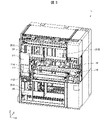
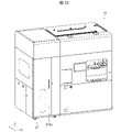
- FIG. 2 is a diagram showing an example of the appearance of the storage device 1.
- Reference numeral 2001 in FIG. 2 indicates an example of the appearance of the storage device 1 when the first door 51 and the second door 52 are closed, and reference numeral 2002 indicates the first door 51 and the second door 52 are open.
- 1 shows an example of the appearance of the storage device 1 in this case.
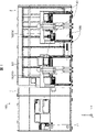
- FIG. 3 is a diagram showing an example of the internal structure of the storage device 1. As shown in FIG.
- the storage device 1 includes a touch panel 20, a first door 51, and a second door 52.
- the touch panel 20 is a display device that displays various information about the storage device 1 and also functions as an input device that receives input operations by the operator.
- the first door 51 is a door that can block the access of the operator to the medicine receiving section 11.
- the first door 51 is a shutter that can slide vertically upward (+Z-axis direction).
- the first door 51 may be locked by a lock mechanism (not shown) when closed.
- the control unit 21 see FIG. 4
- the operator can open the first door 51 .
- the first door 51 By providing the first door 51 , the first door 51 can be closed when the operator does not put the medicine box into the medicine receiving part 11 . Therefore, it is possible to reduce the possibility that the operator carelessly puts his/her hand into the medicine receiving portion 11 . That is, the safety of the storage device 1 can be enhanced. For example, in the later-described storage device 1B, it is possible to reduce the possibility of a worker touching the first transport section 112 in operation when performing automatic filling.
- the second door 52 is a door that allows the worker to access the interior of the storage device 1 .
- the second door 52 is a shutter that can slide vertically downward ( ⁇ Z axis direction).
- the second door 52 may be locked by a lock mechanism (not shown) when closed.
- the control unit 21 receives an input for unlocking the second door 52 via the touch panel 20 when a medicine box transport error occurs inside the storage device 1 (for example, when the medicine box is jammed). is received, the lock by the lock mechanism is released. This allows the operator to open the second door 52 .
- the operator can visually recognize the third transport section 15 and the fifth transport section 19 inside the storage device 1. Therefore, for example, when the medicine boxes are clogged in the third conveying section 15 and the fifth conveying section 19, the operator can remove the medicine boxes to resume filling the storage device 1 with the medicine boxes. It becomes possible.
- the storage device 1 includes a drug receiving section 11, a third transport section 15, a fifth transport section 19, and a storage shelf 30.
- the medicine receiving part 11 is a part that receives the medicine box inserted by the operator.
- the medicine receiving section 11 is provided with a first conveying section 112 and a shutter 114 .
- the first conveying section 112 conveys the medicine box received by the medicine receiving section 11 to the shutter 114 in a state where the medicine box is placed.
- the shutter 114 prevents the medicine box from moving while the first transport section 112 is transporting it toward the second transport section 17 (see FIG. 11).
- the storage shelf 30 is a shelf for storing medicine boxes.
- at least one storage shelf 30 can be installed in a first storage 31A provided on the front side of the storage device 1 and a second storage 31B provided on the back side of the storage device 1.
- the first storage 31A is provided above the fifth transport section 19 and below the drug receiving section 11 and the third transport section 15 .
- the second storage 31B is provided on one surface of the storage device 1 on the back side. 3 shows only the case where one storage shelf 30 is provided above the fifth transport section 19 and one storage shelf 30 is provided below the medicine receiving section 11 and the third transport section 15.
- a plurality of storage racks 30 can be installed in the storage 31A and the second storage 31B.
- a plurality of drug boxes may be arranged in the storage shelf 30 in the depth direction ( ⁇ Y-axis direction) of the storage device 1 .
- at least two of the plurality of medicine boxes may be medicine boxes of the same kind or different kinds.
- the number of medicine boxes stored in a row in the depth direction of the storage device 1 may be determined according to the length of the storage shelf 30 in the depth direction and the length of the medicine boxes.
- a medicine box put into the medicine receiving part 11 is conveyed to the third conveying part 15 by the first conveying part 112 when the shutter 114 is in the open state.
- the third conveying unit 15 sequentially receives the medicine boxes conveyed from the first conveying unit 112, and conveys the received medicine boxes while being spaced apart by a predetermined width.
- the second transport unit 17 grips the medicine box placed on the third transport unit 15 and transports it to the storage shelf 30 .
- the drug box put into the drug receiving section 11 can be stored in the storage shelf 30 .
- the second transport unit 17 grips the medicine box stored in the storage shelf 30 and transports it to the fifth transport unit 19 .
- the medicine boxes stored in the storage shelf 30 can be transported from the storage device 1 to another device (the drug station 2 in this embodiment).
- FIG. 4 is a block diagram showing an example of the configuration of the storage device 1. As shown in FIG. 4 , the white arrows indicate the flow from the medicine box received in the medicine receiving unit 11 until it is stored in the storage shelf 30, and after the medicine box is stored in the storage shelf 30, it is placed in the input box 40. and the flow until it is discharged. FIG. 4 shows only the main configuration for explaining the flow of the medicine box.
- the storage device 1 includes, for example, a medicine receiving portion 11, a width detecting portion 13, a third conveying portion 15, a second conveying portion 17, a fifth conveying portion 19, a control portion 21, a storage portion 23, and a pop-out detecting portion 25.
- a medicine receiving portion 11 includes, for example, a medicine receiving portion 11, a width detecting portion 13, a third conveying portion 15, a second conveying portion 17, a fifth conveying portion 19, a control portion 21, a storage portion 23, and a pop-out detecting portion 25.
- a medicine receiving portion 11 includes, for example, a medicine receiving portion 11, a width detecting portion 13, a third conveying portion 15, a second conveying portion 17, a fifth conveying portion 19, a control portion 21, a storage portion 23, and a pop-out detecting portion 25.
- Specific configurations other than the control unit 21 and the storage unit 23 will be described with reference to drawings other than FIG. 4 .
- the control unit 21 comprehensively controls the storage device 1 (specifically, the transport device 10).
- the storage unit 23 stores information necessary for controlling the storage device 1 (specifically, the transport device 10).
- the control unit 21 includes, for example, a transport control unit 211, a shutter control unit 212, a direction identification unit 213, a storage position management unit 214, and a touch panel control unit 215.
- the transport control unit 211 controls the operations of the first transport unit 112, the third transport unit 15, the second transport unit 17, and the fifth transport unit 19.
- the shutter control unit 212 controls opening and closing operations of the shutter 114 .
- the touch panel control unit 215 controls display on the touch panel 20 .
- the direction specifying unit 213 specifies the direction of the medicine box based on the detection result of the first detection unit 113.
- the orientation identifying unit 213 identifies the orientation of the medicine box based on the detection result of the first detecting unit 113 and the medicine identification information read by the reading unit 111 .
- the direction specifying unit 213 determines whether or not the medicine is oriented in a predetermined direction. In this embodiment, the direction specifying unit 213 determines whether or not the longitudinal direction of the medicine box faces the depth direction of the storage device 1 .
- the transport control unit 211 determines that the medicine box specified by the direction specifying unit 213 is not oriented in the predetermined direction, the transport control unit 211 operates the first transport unit 112 for a predetermined time while the shutter 114 is closed.
- the medicine identification information is information attached to the surface of the medicine box for identifying the medicine contained in the medicine box (eg, information indicating the type of medicine).
- the medicine identification information is an example of information included in the GS1 code, for example, and is attached to the surface of the medicine box in the form of a bar code.
- the medicine identification information may be any information that can identify the medicine contained in the medicine box, and may be realized by information other than the GS1 code.
- the medicine identification information may be in a format readable by the reading unit 111, and may be attached in a format other than a barcode.
- the information attached to the surface of the medicine box may include medicine identification information indicating the type of medicine, as well as information indicating the expiration date, lot number, and number of medicines stored in the medicine box. Note that the expiration date may also be referred to as the expiration date.
- the longitudinal direction of the medicine box is the direction along the longest side of the sides defining the medicine box
- the short direction of the medicine box is the direction along the shortest side of the sides defining the medicine box. direction.
- the shape of the medicine box is a substantially rectangular parallelepiped.
- the storage position management section 214 manages the storage position in the storage shelf 30 of the medicine box received by the medicine receiving section 11 .
- the storage position management unit 214 specifies the size of the medicine box received by the medicine receiving unit 11, for example, by referring to the medicine database stored in the storage unit 23 based on the medicine identification information read by the reading unit 111. do.
- Storage position management unit 214 determines the storage position of the medicine box in storage shelf 30 based on the specified size of the medicine box and the storage position information stored in storage unit 23 .
- a drug database manages information on multiple types of drugs.
- the drug database manages, for example, information indicating the size (eg, length, width, and height) of a drug box containing a drug in association with each of a plurality of types of drugs.
- the storage position information is information indicating the storage position of the drug (specifically, the drug box) in the storage shelf 30 .
- the storage location management unit 214 can identify the empty area in the storage shelf 30 by referring to the storage location information.
- the storage position management unit 214 updates the storage position information, for example, when the storage position of the medicine box is determined and when an instruction to take out the medicine box is received.
- the storage position management section 214 may update the storage position information so as to include the storage position of the medicine box.
- the storage position management unit 214 may update the storage position information so as to delete the storage position of the medicine box (to make it an empty area).
- Storage location information may be updated. For example, when the storage position management unit 214 receives a detection signal indicating that a medicine box has been detected from the passage detection unit 1751 (see FIG. 11) provided in the grip unit 171 of the second transport unit 17, the storage position management unit 214 stores the storage position information. By referring to it, it is determined whether the medicine box has been stored or taken out. The storage location management unit 214 may update the storage location information based on this determination result.
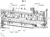
- Reference numerals 5001 and 5002 in FIG. 5 are perspective views showing an example of the configuration of the medicine receiving portion 11 and its surroundings.
- the arrow at reference numeral 5001 in FIG. 5 indicates the transport direction of the medicine box in the third transport section 15 .
- FIG. 6 is a perspective view showing an example of the drug receiving portion 11. As shown in FIG.
- the medicine receiving portion 11 is a space formed by a first side wall portion 116, a second side wall portion 117, a shutter 114, a first conveying portion 112, and a top surface portion 118. Further, the first side wall portion 116 , the shutter 114 , the first conveying portion 112 and the top surface portion 118 form an opening for receiving the medicine box in the medicine receiving portion 11 .
- the first side wall portion 116 is a side wall portion facing the shutter 114 .
- the second side wall portion 117 is a side wall portion facing the opening. Further, the shutter 114 functions as part of the side wall of the drug receiving portion 11 , and the first conveying portion 112 functions as the bottom portion of the drug receiving portion 11 .
- a reading part 111 for reading medicine identification information attached to the surface of the medicine box there is provided a reading part 111 for reading medicine identification information attached to the surface of the medicine box.
- the medicine identification information is attached to the surface of the medicine box in the form of a bar code. Therefore, in this embodiment, the reading unit 111 is a barcode reader.
- the reading unit 111 may be any device capable of reading the medicine identification information attached to the surface of the medicine box.
- the reading unit 111 transmits the read drug identification information to the control unit 21 .
- the control unit 21 causes the notification unit (not shown) to output a sound (eg, BEEP sound). That is, the control unit 21 causes the notification unit to notify that the reading unit 111 has read the medicine identification information.
- a sound eg, BEEP sound
- the control unit 21 causes the notification unit to notify that the reading unit 111 has read the medicine identification information.
- the operator can put the next medicine box into the medicine receiving part 11 and cause the reading part 111 to read the medicine identification information attached to the medicine box. That is, the storage device 1 can continuously receive medicine boxes in the medicine receiving section 11 .
- control unit 21 may drive the reading unit 111 when receiving an input for manual filling via the touch panel 20 .
- a plurality of reading units 111 are provided inside the medicine receiving unit 11 .
- reading units 111A to 111C are provided as shown in FIG.
- the reading portion 111A is provided on the first side wall portion 116 so that the reading direction of the medicine identification information is substantially orthogonal to the second side wall portion 117 .
- the reading portion 111B is provided on the second side wall portion 117 so that the reading direction of the medicine identification information is substantially orthogonal to the first side wall portion 116 .
- Reading unit 111 ⁇ /b>C is provided on top surface 118 so that the medicine identification information can be read in a direction substantially perpendicular to top surface 118 .
- only one reading unit 111 may be provided near the medicine receiving unit 11 in the housing of the storage device 1 . Even in this case, the reading unit 111 can read the medicine identification information attached to the medicine box. However, in this case, in order for the reading unit 111 to read the medicine identification information, the operator confirms where the barcode is attached to the medicine box, and then reads the barcode-attached surface. It is necessary to turn to the 111 side.
- the barcode attached to the medicine box is relatively small compared to the medicine box, and the position of the barcode is different for each manufacturer. Therefore, it may be a burden for the operator to check which position of the medicine box the barcode is attached. In addition, if confirmation takes time, the efficiency of the medicine box storage operation will be reduced accordingly.
- the reading unit 111 can read the drug identification information. Also, as described above, the operator can confirm whether or not the medicine identification information has been read. Therefore, the operator can cause the reading unit 111 to read the medicine identification information simply by rotating the medicine box until a sound is output without being conscious of the position of the barcode on the medicine box. Therefore, it is possible to reduce the burden on the operator and reduce the possibility that the efficiency of the storage work will be lowered.
- the reading units 111A to 111C when the reading units 111A to 111C are provided so that the reading directions of the reading units 111A to 111C are orthogonal to each other, as in the present embodiment, the reading units 111A to 111C read the medicine box inserted inside the medicine receiving unit 11. It is possible to simultaneously irradiate reading light from three mutually orthogonal directions. Therefore, it is possible to further improve the reading efficiency of the medicine identification information. However, if a plurality of reading units 111 are provided in the drug receiving unit 11, the burden on the operator for reading the drug identification information can be reduced.
- the first transport unit 112 transports the medicine box received by the medicine receiving unit 11 to the shutter 114 while it is placed thereon.
- the 1st conveyance part 112 is a belt conveyor.
- the transport control unit 211 causes the first transport unit 112 to forward after receiving the medicine identification information read by the reading unit 111 .
- Forward feeding of the first conveying unit 112 means operating the conveying belt of the first conveying unit 112 to convey the placed medicine box toward the shutter 114 (+X-axis direction).
- the first transport control unit 211 operates the transport belt of the first transport unit 112 to transport the placed medicine box toward the first side wall unit 116 ( ⁇ X axis direction). It is also referred to as reversing the conveying unit 112 .
- the shutter 114 is provided between the first transport section 112 and the third transport section 15 and is opened and closed under the control of the shutter control section 212 .
- the shutter 114 is closed when the medicine receiving portion 11 can receive the medicine box. Further, the shutter 114 prevents movement of the medicine box transported to the third transporting part 15 side by the first transporting part 112 in the closed state.
- the shutter 114 functions as a side contact portion having a side surface 1141 (contact surface) with which one side surface of the medicine box being conveyed by the first conveying portion 112 contacts. That is, in the present embodiment, the first transport section 112 transports the medicine box received by the medicine receiving part 11 so that one side surface of the medicine box is brought into contact with the side surface 1141 .
- the shutter 114 performs opening and closing operations in the vertical direction ( ⁇ Z-axis direction).
- the first detection unit 113 is a detection unit that detects a medicine box that is in contact with or close to the shutter 114 .
- the first detection unit 113 includes a plurality of sensors 1131 that detect the presence or absence of an object by outputting light.
- the plurality of sensors 1131 are provided along one side included in the side surface 1141 of the shutter 114 and capable of contacting the first conveying unit 112, as indicated by reference numeral 5001 in FIG. It is That is, the plurality of sensors 1131 are provided along the ⁇ Y-axis direction at the lower end of the side surface 1141 .
- a plurality of sensors 1131 are provided on the side surface 1141 of the shutter 114 so as to emit light in a direction substantially perpendicular to the side surface 1141 of the shutter 114 .
- the sensor 1131 is a reflective sensor that includes an emitting portion that emits light and a light receiving portion that receives the reflected light after the emitted light is reflected by the object.
- the first detection unit 113 transmits to the control unit 21 a detection signal indicating that the medicine box has been detected. Further, the first detection unit 113 includes information indicating which sensor 1131 among the plurality of sensors 1131 has detected the medicine box in the detection signal and transmits the detection signal to the control unit 21 . Thereby, the control unit 21 can determine whether or not the medicine box is detected. Further, the direction specifying unit 213 compares the arrangement position of the sensor 1131 that detects the medicine box with the size of the medicine box obtained by referring to the medicine database based on the medicine identification information read by the reading unit 111. . Thereby, the direction specifying unit 213 can specify which surface of the medicine box is close to or in contact with the side surface 1141 of the shutter 114 . Therefore, the direction identifying unit 213 can identify whether or not the medicine box that is close to or in contact with the side surface 1141 of the shutter 114 is oriented in a predetermined direction.
- the first detection unit 113 only needs to be able to identify how the medicine box is in contact with the side surface 1141 of the shutter 114 .
- the plurality of sensors 1131 may be provided in a plurality of rows, or may emit electromagnetic waves other than light or sound waves (eg, ultrasonic waves).
- the first detection unit 113 may be an imaging unit provided on the top surface 118 adjacent to the shutter 114 .
- the orientation identification unit 213 can identify the orientation of the medicine box by analyzing the image of the medicine box captured by the imaging unit. That is, the direction specifying unit 213 can specify the direction of the medicine box based on the detection result of the first detection unit 113 as an imaging unit.
- the entrance/exit detector 115 is provided in the medicine receiving part 11 on the front side of the first transport part 112 (on the medicine box receiving side).
- the entrance/exit detection unit 115 includes a plurality of sensors that detect the presence or absence of an object by outputting light.
- the plurality of sensors are arranged in a row in the ⁇ X-axis directions.
- the sensor is a reflective sensor.
- the control unit 21 When the sensor detects an object, it transmits a detection signal indicating that the object has been detected to the control unit 21 . Thereby, the control unit 21 can determine whether or not the operator's hand and arm are inserted into the medicine receiving unit 11 . Therefore, the shutter control unit 212 does not operate the shutter 114 when the operator's hand and arm are inserted into the medicine receiving part 11, and the operator's hand and arm are not inserted into the medicine receiving part 11. The shutter 114 can be operated only when Therefore, it is possible to reduce the possibility of an accident in which the operator's hand and arm are caught in the operation of the shutter 114 .
- the entrance/exit detection unit 115 may be provided so as to be able to determine whether or not the operator's hand and arm are inserted inside the medicine receiving unit 11 .
- the entrance/exit detection unit 115 may be provided on the front side of the shutter 114 , the first side wall portion 116 and/or the top surface portion 118 .
- the entrance/exit detection portion 115 is realized as a transmissive sensor.
- the plurality of sensors included in the entrance/exit detection unit 115 may be arranged in a plurality of rows, and may emit electromagnetic waves other than light or sound waves (eg, ultrasonic waves).
- the third transport unit 15 is controlled by the first transport unit 114 via the shutter 114 so as to sequentially receive the medicine boxes transported from the first transport unit 112 while the shutter 114 is open. Attached to 112.
- the 3rd conveyance part 15 is a belt conveyor.
- the third transport section 15 includes a 3-1 transport section 15A and a 3-2 transport section 15B.
- the 3-1 conveying section 15A conveys the medicine boxes received from the first conveying section 112 while being spaced apart by a predetermined width.
- the 3-1 conveying section 15A is installed side by side with the first conveying section 112 via a shutter 114 so as to sequentially receive the medicine boxes conveyed from the first conveying section 112 .
- the 3-2 conveying section 15B conveys the medicine boxes received from the 3-1 conveying section 15A while being separated by a predetermined width.
- the 3-2 transport unit 15B is installed side by side with the 3-1 transport unit 15A in the depth direction ( ⁇ Y axis direction) of the storage device 1, and transports the medicine box in the opposite direction to the 3-1 transport unit 15A. transport.
- a drug moving section 151 for moving the drug box is provided between the end of the 3-1 conveying section 15A and the opposite end.
- the drug moving unit 151 includes a push plate 1511, a timing belt 1512, and a driving unit 1513.
- a push plate 1511 is fixed to a portion of a timing belt 1512, and the timing belt 1512 is attached to two drive shafts. Also, one drive shaft is connected to the drive section 1513 .
- the transport control unit 211 can operate the timing belt 1512 by driving the drive unit 1513, and can move the ejection plate 1511 in the ⁇ Y-axis direction corresponding to this operation.
- the push plate 1511 pushes the drug box that has reached the end of the 3-1 transport section 15A to the 3-2 transport section 15B, whereby the drug moving section 151 moves the drug box to the 3-2 transport section 15B. It can be moved from the 3-1 transport section 15A to the 3-2 transport section 15B.
- the transport control unit 211 moves the medicine box to the 3-2 transport unit 15B, and then moves the ejector plate 1511 toward the 3-1 transport unit 15A.
- the medicine moving section 151 can sequentially move the medicine boxes from the 3-1 conveying section 15A to the 3-2 conveying section 15B.
- the transport control unit 211 causes the 3-2 transport unit 15B to move from the 3-1 transport unit 15A.
- the mounting surface of the 3-2 conveying section 15B may be moved toward the pushing plate 1511 side. That is, after the 3-2nd transport unit 15B receives the medicine box from the 3-1st transport unit 15A, the transport control unit 211 moves the loading surface of the 3-2nd transport unit 15B in the direction of the arrow shown in FIG. You can move it in the opposite direction.
- the orientation of the medicine box can be adjusted.
- the transport control unit 211 sequentially feeds the first transport unit 112 and the third transport unit 15.
- To feed the third conveying portion 15 forward means to operate the conveying belt of the 3-1 conveying portion 15A to convey the placed medicine box in the direction (+X-axis direction) away from the shutter 114.
- forward feeding of the third conveying section 15 means that the conveying belt of the 3-2 conveying section 15B is conveyed in a direction ( ⁇ X axis direction) toward the shutter 114 side of the placed medicine box. means to operate.
- the transport control unit 211 stops the third transport unit 15 after operating it for a predetermined time.
- the medicine boxes can be conveyed in the third conveying section 15 in a state where the medicine boxes are spaced apart by a predetermined width. That is, the predetermined time for operating the third conveying unit 15 is set to a time during which the adjacent medicine boxes can be spaced apart from each other by a predetermined width.
- the predetermined width may be set to such a width that when gripping portion 171 of second conveying portion 17 grips a medicine box, it does not come into contact with the medicine box adjacent to the medicine box to be gripped. In this embodiment, it is set to 15 mm, for example.
- the transport control unit 211 may stop the first transport unit 112 when the third transport unit 15 is stopped.
- the transport control unit 211 may control the second transport unit 17 to sequentially transport medicine boxes placed on the third transport unit 15 to storage positions determined by the storage position management unit 214 .
- the second transport unit 17 may be controlled to transport the drug box to the storage position.
- the transport control unit 211 causes the second transport unit 17 to move when the number of medicine boxes on the third transport unit 15 matches the maximum number of medicine boxes that can be placed on the third transport unit 15.
- the medicine boxes may be controlled and transported to the storage positions determined by the storage position management unit 214 in order from the first medicine box.
- the transport control unit 211 may sequentially feed the medicine boxes on the third transport unit 15 in accordance with the timing of gripping the medicine boxes by the second transport unit 17 .
- the control part 21 causes the medicine boxes whose medicine identification information is read by the reading part 111 to be placed on the first transport part 112.
- the medicine box can be transported onto the third transport section 15 . That is, after the medicine box is gripped by the second conveying section 17, the shutter control section 212 opens the shutter 114. FIG. Thereafter, the transport control unit 211 drives the first transport unit 112 and the third transport unit 15 so that the medicine box on the first transport unit 112 can be placed on the third transport unit 15 .
- control unit 21 can count the number of medicine boxes placed on the third transport unit 15 by detection of medicine boxes by the width detection unit 13, for example.
- the storage unit 23 also stores information indicating the maximum number of medicine boxes that can be placed on the third transport unit 15 .
- the gripping position of the medicine box by the second transport section 17 may be specified on the third transport section 15 . In this case, the number of medicine boxes that can be placed on the third conveying unit 15 between the shutter 114 and the gripping position is the maximum number.
- the width detection unit 13 detects the width of the medicine box.
- the width detector 13 is, for example, a reflective sensor.
- the width detection unit 13 detects medicine boxes passing in front of the width detection unit 13 .
- the width detection unit 13 is located near the 3-1 conveying unit 15A and the shutter 114, and the detection direction (light emission direction) of the medicine box is the medicine by the 3-1 conveying unit 15A. It is provided at a position substantially perpendicular to the transport direction of the box.
- the orientation of the medicine box is adjusted by the first conveying unit 112 and the shutter 114 so that the longitudinal direction of the medicine box matches the depth direction of the storage device 1 . Therefore, the medicine box passes in front of the width detection part 13 so that the side surface of the medicine box perpendicular to the longitudinal direction faces the width detection part 13 .
- the transport control unit 211 for example, based on the detection time of the medicine box by the width detection unit 13 and the movement speed of the transport belt of the 3-1 transport unit 15A (transportation speed of the medicine box), determines the width of the medicine box (the medicine box transport speed). 3-1
- the width along the ⁇ X-axis direction in the state of being placed on the transport unit 15A can be calculated. Therefore, when the gripping portion 171 of the second transporting portion 17 grips the medicine box, the transport control portion 211 can open the gripping portion 171 in the ⁇ X-axis directions larger than the calculated width of the medicine box.
- the width detection unit 13 may be provided so as to identify the passage of the medicine box.
- the width detection unit 13 may be implemented as a transmissive sensor, or may emit electromagnetic waves other than light or sound waves (eg, ultrasonic waves).
- the width detection unit 13 may be implemented as an imaging unit.
- a detection unit that detects an object may be a reflective or transmissive sensor, may emit electromagnetic waves or sound waves, or may be an imaging unit. may be
- the third transport unit 15 having the 3-1 transport unit 15A and the 3-2 transport unit 15B which is the present embodiment, the 3-1 transport unit 15A and the 3-2 transport unit 15B are operated. It is preferable that the user can set so that the mode can be switched between a mode in which only the 3-1 conveying section 15A is operated. Further, in the present embodiment, the third transport section 15 is implemented by the 3-1 transport section 15A and the 3-2 transport section 15B, but is not limited to this. In other words, the storage device 1 does not need to include a plurality of third transport sections 15, and may be configured to include only one third transport section 15 (3-1 transport section 15A).
- the operator inserts the medicine box into the medicine receiving part 11, causes the reading part 111 to read the medicine identification information, and then places the medicine box on the first transport part 112. By placing it, the medicine box can be transported from the first transport section 112 to the third transport section 15 .
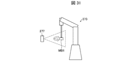
- the storage device 1B of Embodiment 3 for example, after the robot arm 273 (see FIGS. 27 and 28) causes the reading unit 277 (see FIG. 24) to read the drug identification information, A medicine box is placed on the first transport section 112 .
- the automatic refillable storage device 1B may be configured to include one third transport section 15 .
- the storage device 1 has only one third transport unit 15 (here, it is assumed to have the 3-1 transport unit 15A)
- the storage device 1 as indicated by reference numeral 5001 in FIG.
- a detection unit 121 may be provided.
- the position detection unit 121 detects a medicine box that is close to or in contact with the side surface 1141 of the shutter 114 .
- the position detection unit 121 may be, for example, a reflective sensor.
- the position detection section 121 is provided at a position of the second side wall section 117 adjacent to the side surface 1141 of the shutter 114 . Further, the position detection portion 121 is provided at substantially the same height as the first detection portion 113 on the second side wall portion 117 . Like the first detection section 113 , the position detection section 121 may be provided at a position where it can detect the medicine box that is close to or in contact with the side surface 1141 of the shutter 114 .
- the control unit 21 identifies the position of the medicine box in the depth direction of the storage device 1 in the first transport unit 112 based on the detection result of the position detection unit 121 .
- the control unit 21 specifies the position of the medicine box based on the time from when the position detection unit 121 emits light to when the light is reflected by the medicine box and when the reflected light is received. As a result, the control unit 21 can specify the position of the medicine box transported from the first transport unit 112 to the 3-1 transport unit 15A in the depth direction of the storage device 1 in the 3-1 transport unit 15A. .
- the grasping section 171 of the 2nd conveying section 17 takes out the medicine box from the 3-1 conveying section 15A.
- the operator places the medicine box on the first transport section 112 without much awareness of its position on the first transport section 112 . Therefore, there is a high possibility that the positions of the medicine boxes in the depth direction of the storage device 1 in the 3-1 conveying section 15A are different for each medicine box. Therefore, the transport control unit 211 needs to specify the position of the medicine box in order to allow the grasping part 171 to take out the medicine box.
- the grasping unit 171 can accurately grasp the medicine box placed on the 3-1 transport unit 15A even when the positions of the medicine boxes are different.
- the storage apparatus 1 includes a 3-1 transport section 15A and a 3-2 transport section 15B as the third transport section 15, and the drug placed on the 3-1 transport section 15A is The box is conveyed to the 3-2 conveying section 15B by the medicine moving section 151.
- the control unit 21 determines the amount of movement of the medicine moving unit 151 when carrying out this transportation. may be specified. In this case, the positions of the medicine boxes in the depth direction in the 3-2 conveying section 15B can be aligned on the second conveying section 17 side. Therefore, the gripping section 171 can accurately grip the medicine box placed on the 3-2 conveying section 15B.
- the control unit 21 determines which surface of the medicine box corresponds to the side surface 1141 of the shutter 114. It is possible to specify at which position the two are in proximity or contact. Therefore, the position detection portion 121 does not have to be provided on the second side wall portion 117 .
- the position detection section 121 functions as an auxiliary detection section for the first detection section 113 .
- the width detection unit 13 may have the function of the position detection unit 121 . Also in this case, the position detection portion 121 does not need to be provided on the second side wall portion 117 .
- the ejector plate 1511 can be reciprocated between the position on the 3-1 conveying section 15A and the 3-2 conveying section 15B and the position on the housing side where the timing belt 1512 is provided. good.
- the ejector plate 1511 may be provided rotatably around a rotating shaft extending in the movement direction ( ⁇ Y-axis direction) of the ejector plate 1511 and provided in the housing.
- the transport control unit 211 when moving the ejector plate 1511 from the 3-1 transport unit 15A to the 3-2 transport unit 15B, moves the ejector plate 1511 from the 3-1 transport unit 15A to the 3rd -2 Move while positioned on the conveying section 15B.
- the transport control unit 211 moves the ejector plate 1511 from the 3-2 transport unit 15B to the 3-1 transport unit 15A
- the transport control unit 211 moves the ejector plate 1511 in a retracted state toward the housing.
- the operation (returning operation) of moving the ejector plate 1511 from the 3-2nd conveying portion 15B to the 3-1st conveying portion 15A and the operation of conveying the medicine box by the 3-1st conveying portion 15A are performed in parallel. can run.
- FIG. 7 An example of operation for receiving a medicine box into the storage device 1 will be described with reference to FIGS. 7 to 10.
- FIG. 1 the medicine boxes are placed on the storage shelf 30 such that the longitudinal direction of the medicine boxes coincides with the depth direction ( ⁇ Y-axis direction) of the storage device 1 .
- the second transport unit 17 stores the medicine box placed on the third transport unit 15 in the storage rack 30 with the direction unchanged or rotated by 180 degrees. The orientation of the medicine box is not changed in the transportation of the third transportation unit 15 . Therefore, in order to store the medicine box in the storage shelf 30 as described above, the medicine receiving part 11 is adjusted so that the longitudinal direction of the medicine box is oriented in the ⁇ Y-axis direction.
- FIG. 7 is a diagram showing an example of a process in which the medicine box MB1 placed on the first transport section 112 is transported to the 3-1 transport section 15A.
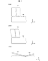
- FIG. 8 is a diagram showing an example of a process for adjusting the orientation of the medicine box MB1 received by the medicine receiving section 11. As shown in FIG.
- the operator puts the medicine box MB1 into the medicine receiving part 11 while holding it.
- the entrance/exit detection unit 115 transmits a detection signal indicating that the object (hand or arm of the operator) has been detected to the control unit 21 .
- the control unit 21 operates the reading unit 111 so that the medicine identification information can be read.
- the control unit 21 When the reading unit 111 reads the medicine identification information attached to the medicine box MB1 put into the medicine receiving unit 11, the control unit 21 outputs a sound for notifying that the medicine identification information has been read from the notification unit. to output Further, when the reading unit 111 reads the medicine identification information, the transport control unit 211 operates the first transport unit 112 to forward the first transport unit 112 as indicated by reference numeral 7001 in FIG. As a result, the medicine box MB1 is transported to the shutter 114, as indicated by reference numeral 7002 in FIG.
- the first detection unit 113 provided on the side surface 1141 of the shutter 114 detects the medicine box MB1.
- the transport control unit 211 receives a detection signal indicating that the medicine box MB1 has been detected from the first detection unit 113, the transport control unit 211 temporarily stops the transport of the medicine box MB1 by the first transport unit 112.
- the direction identification unit 213 determines whether or not the medicine box MB1 detected by the first detection unit 113 is oriented along the side surface 1141 of the shutter 114 ( ⁇ Y-axis direction). judge. In this embodiment, the direction specifying unit 213 determines whether or not the longitudinal direction of the medicine box MB1 is oriented in the ⁇ Y-axis direction.
- the first detection unit 113 also causes the detection signal to include information indicating which sensor 1131 has detected the medicine box. Furthermore, the control unit 21 can acquire information indicating the size of the medicine box by referring to the medicine database based on the medicine identification information read by the reading unit 111 . Therefore, the control unit 21 can specify the size of the medicine box in the direction along the side surface 1141 of the shutter 114 based on these pieces of information. That is, the direction specifying unit 213 can determine whether the longitudinal direction of the medicine box MB1 faces the direction along the side surface 1141 of the shutter 114 and is in proximity to or in contact with the shutter 114 based on these pieces of information.
- the direction specifying unit 213 determines that the longitudinal direction of the medicine box MB1 is oriented along the side surface 1141 of the shutter 114.
- the shutter control unit 212 determines whether or not a detection signal indicating that the object (hand or arm of the worker) has been detected has been received from the entrance/exit detection unit 115 .
- the shutter control unit 212 closes the shutter. 114 is opened. That is, the shutter control section 212 starts the operation of opening the shutter 114 when the operator's hand or arm is not inserted into the medicine receiving section 11 .
- the plurality of sensors 1131 of the first detection unit 113 provided on the shutter 114 are provided along one side of the side surface 1141 of the shutter 114 that can come into contact with the first conveying unit 112. . Moreover, the plurality of sensors 1131 emit light in a direction substantially perpendicular to the side surface 1141 of the shutter 114 . Therefore, when the shutter 114 moves vertically upward, the plurality of sensors 1131 cannot detect the medicine box when the upper end of the medicine box placed on the first transport section 112 is passed.
- the shutter control unit 212 may stop the operation of the shutter 114 after a predetermined distance or a predetermined period of time has elapsed since the plurality of sensors 1131 became unable to detect the medicine box. In this case, every time the shutter 114 is opened, it is not necessary to open the shutter 114 to the highest movable range of the shutter 114, and the shutter 114 can be opened according to the height of the medicine box.
- the shutter control unit 212 sets the position at which the operation of the shutter 114 is stopped, that is, the height of the medicine box detected by the first detection unit 113 with respect to the medicine box whose medicine identification information is read by the reading unit 111. It is determined whether or not the height is equal to or higher than the set value.
- the shutter control unit 212 can acquire the height of the medicine box received by the medicine receiving unit 11 by referring to the medicine database stored in the storage unit 23 based on the medicine identification information read by the reading unit 111.
- the height obtained by adding a predetermined value to the height of each medicine box registered in the medicine database is stored in advance as a setting value set for each medicine box.
- the control unit 21 may calculate the set value by adding the predetermined value when the height of the medicine box received by the medicine receiving unit 11 is acquired.
- a margin (for example, several millimeters) may be set so as not to allow conveyance to the 3-1 conveying section 15A.
- the transport control unit 211 restarts transport of the medicine box MB1 by the first transport unit 112. .
- the transport control unit 211 also forwards the third transport unit 15 .
- the medicine box MB1 can be placed on the 3-1 conveying section 15A so that the interval between the adjacent medicine boxes becomes a predetermined width. That is, the interval W2 between the medicine box MB2 already placed on the 3-1 transport section 15A and the medicine box MB3, and the distance between the medicine box MB2 and the medicine box MB1 transported to the 3-1 transport section 15A.
- the medicine boxes MB1 to MB3 can be placed on the 3-1 conveying section 15A with W1 being substantially the same.
- the transport control unit 211 forwards the first transport unit 112 .
- the first transport unit 112 transports the medicine box MB1 to the shutter 114 side.
- the transport control unit 211 temporarily stops the transport of the medicine box MB1 by the first transport unit 112.
- the first detection unit 113 cannot detect the medicine box MB1 over the entire length of the medicine box MB1 along the longitudinal direction of the medicine box MB1. Therefore, as indicated by reference numeral 8002, the transport control unit 211 restarts transport of the medicine box MB1 by the first transport unit 112 while the shutter 114 remains closed. As a result, since the first conveying unit 112 is sequentially fed while the medicine box MB1 is in contact with the side surface 1141 of the shutter 114, the longitudinal direction of the medicine box MB1 is aligned with the side surface 1141 of the shutter 114 as indicated by reference numeral 8003. can be directed to
- the direction specifying part 213 determines whether or not the longitudinal direction of the medicine box MB1 is along the side surface 1141 of the shutter 114 based on the detection result of the first detecting part 113. judge.
- the control unit 21 controls the shutter 114, the first transport section 112 and the third transport section 15 as described above. That is, as indicated by reference numerals 7002 and 7003, the medicine box MB1 on the first transport section 112 is transported onto the 3-1 transport section 15A after the shutter 114 is opened.
- the longitudinal direction of the medicine box is oriented along the side surface 1141 of the shutter 114 by the first conveying part 112 and the shutter 114 regardless of the orientation of the medicine box placed on the first conveying part 112. can be conveyed to the third conveying unit 15 in this state. Therefore, the medicine boxes received by the medicine receiving part 11 can be continuously placed on the third conveying part 15 in a state in which the directions of the medicine boxes are aligned. Therefore, the second conveying unit 17 can sequentially grip the medicine boxes with a simple mechanism.
- the drug boxes can be stored in the storage shelf 30 with the directions of the drug boxes aligned.
- the medicine box can be stored in the storage shelf 30 so that the longitudinal direction of the medicine box faces the depth direction of the storage device 1 .
- the longitudinal direction of the medicine box received by the medicine receiving part 11 can be oriented along the side surface 1141 of the shutter 114 . That is, the orientation of the medicine box received by the medicine receiving part 11 can be adjusted in the above-described direction by the simple configuration of the first conveying part 112 and the shutter 114 .
- the transport control section 211 can control the first transport section 112 and the third transport section 15 independently. Therefore, when the longitudinal direction of the medicine box is not in the direction along the side surface 1141 of the shutter 114, the transport control unit 211 keeps the shutter 114 closed while the first transport unit 112 is forwarded. The transport section 15 can be stopped. Then, the transport control unit 211 controls the first transport unit 112 and the third transport unit 15 in a state where the drug box is located at the position of the shutter 114 and the longitudinal direction of the drug box faces the direction along the side surface 1141 of the shutter 114 . to drive. As a result, a plurality of medicine boxes can be placed on the third conveying section 15 while maintaining a constant positional interval between the medicine boxes.
- the transport control unit 211 can independently control the first transport unit 112 and the third transport unit 15, the transport amount of the first transport unit 112 and the transport amount of the third transport unit 15 can be set respectively.
- the feed amount is the speed at which the conveying belt of the first conveying unit 112 or the conveying belt of the third conveying unit 15 is forwarded. Therefore, for example, the positional interval between the two medicine boxes can be arbitrarily set according to the feeding amount of the third conveying part 15 after conveying the medicine boxes from the first conveying part 112 to the third conveying part 15 .
- FIG. 9 is a diagram showing an operation example of the first transport section 112 and the shutter 114 when another medicine box MB2 is stacked on top of the medicine box MB1 placed on the first transport section 112.
- FIG. Reference numeral 9001 in FIG. 9 shows a state in which another medicine box MB2 is stacked on top of the medicine box MB1 placed on the first transport section 112 and transported to the shutter 114.
- the direction specifying unit 213 determines that the medicine box MB ⁇ b>1 is oriented along the side surface 1141 of the shutter 114 . Therefore, if a detection signal is received from the entrance/exit detection unit 115, the shutter control unit 212 opens the shutter 114 as indicated by reference numeral 9002 in FIG.
- the shutter control unit 212 when the height of the medicine box detected by the first detection part 113 is equal to or higher than the set value set for the medicine box whose medicine identification information is read by the reading part 111, the shutter control unit 212 , the shutter 114 is closed.
- shutter control unit 212 determines that the height of the medicine box detected by first detection unit 113 is equal to or greater than the set value set for medicine box MB1. , the shutter 114 is closed. In FIG. 9, the medicine box MB2 is placed on the medicine box MB1. Therefore, the shutter control unit 212 determines that the heights of the medicine boxes MB1 and MB2 detected by the first detection unit 113 are equal to or higher than the set value set for the medicine box MB1. The shutter 114 is closed as indicated by reference numeral 9003 . Then, as indicated by reference numeral 9004, the transport control unit 211 causes the first transport unit 112 to feed backward.
- the transport control unit 211 does not transport the medicine box placed on the first transport unit 112 to the third transport unit 15 . Therefore, in the third transport unit 15, the possibility that the medicine box is stacked on another medicine box can be reduced, and the medicine boxes can be placed one by one. Therefore, the second conveying unit 17 can grip the medicine boxes one by one.
- the shutter 114 when the shutter 114 is in an open state, it means that one medicine box whose medicine identification information has been read can pass through, and that a plurality of stacked medicine boxes are not allowed to pass through. indicates a state in which the shutter 114 is open. Further, the closed state of the shutter 114 indicates a state in which one medicine box whose medicine identification information is read cannot pass through.
- the shutter control unit 212 changes the shutter 114 to the closed state. may be maintained. Also, the transport control unit 211 does not have to reverse the first transport unit 112 . Also, the control unit 21 may use the touch panel 20, a lighting member (not shown), or the like to notify that the medicine box cannot be stored.
- FIG. 10 is a diagram showing an operation example of the first conveying section 112 when the longitudinal direction of the medicine box MB faces the forward feeding direction.
- the shutter 114 is opened when the longitudinal direction of the medicine box MB faces the direction along the side surface 1141 of the shutter 114 .
- the first detection unit 113 detects the medicine box MB over the entire length of the medicine box MB along the lateral direction of the medicine box MB.
- the shutter control unit 212 keeps the shutter 114 closed.
- the transport control unit 211 causes the first transport unit 112 to move backward.
- the control unit 21 may use the touch panel 20 or a lighting member (not shown) or the like to notify that the medicine box MB cannot be stored.
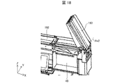
- FIG. 11 is a perspective view showing an example of the configuration of the second conveying section 17. As shown in FIG. In FIG. 11, illustration of the second storage 31B side is omitted.
- the second transport unit 17 is a device for gripping a drug box containing drugs and transporting the drug box to an arbitrary position.
- the second transport unit 17 stores the medicine box in the storage shelf 30 by transporting the medicine box from the third transport unit 15 to the storage position determined by the storage position management unit 214 .
- the second transport unit 17 transports the drug box containing the drug from the storage shelf 30 to the fifth transport unit 19. By doing so, the drug box is ejected to the outside.
- the second conveying section 17 includes a gripping section 171 and a conveying mechanism (lifter) 172 .
- Only one second transportation unit 17 may be provided in the storage device 1, or a plurality of the second transportation units 17 may be provided.
- two second transport units 17 are provided between the first storage 31A and the second storage 31B along the two first storage 31A and the second storage 31B provided in the storage device 1. may be
- the transport mechanism 172 is an action part for moving the grip part 171 to an arbitrary position within the storage device 1 .
- the transport mechanism 172 includes an X-axis rail portion 1721, a post 1722, an X-axis timing belt 1723, a Z-axis driving portion 1724, a Z-axis timing belt 1725, an X-axis driving portion 1726, an auxiliary timing belt 1727, and drive shaft 1728 .
- the X-axis rail portion 1721 is provided along the width direction ( ⁇ X-axis direction) of the storage device 1, and supports the strut 1722 so as to be slidable in the ⁇ X-axis direction. As shown in FIG. 11, the X-axis rail portion 1721 may be provided on both the top surface portion side and the floor surface portion side of the storage device 1 . That is, the column 1722 may be slidably supported in the ⁇ X-axis directions by the X-axis rail portions 1721 at both ends thereof.
- the strut 1722 is provided along the vertical direction ( ⁇ Z-axis direction) and supported by the X-axis rail portion 1721 .
- the strut 1722 is slidable in the ⁇ X-axis directions along the X-axis rail portion 1721 and supports the grip portion 171 .
- the strut 1722 is connected to an X-axis timing belt 1723 arranged along the X-axis rail portion 1721 .
- the X-axis timing belt 1723 on the top surface side of the storage device 1 is connected to one end of the drive shaft 1728 .
- the other end of drive shaft 1728 is connected to X-axis drive section 1726 via auxiliary timing belt 1727 .
- the X-axis timing belt 1723 on the floor side of the storage device 1 is also connected to the X-axis driving section 1726 .
- the X-axis timing belt 1723 can rotate according to the operation of the X-axis drive section 1726 controlled by the transport control section 211 . Therefore, the support 1722 can move along the X-axis rail portion 1721 .
- FIG. 12 is a perspective view showing an example of the configuration of the grip portion 171.
- the grasping unit 171 grasps the medicine box and moves it with the operation of the transport mechanism 172 to move the medicine box to an arbitrary position. Specifically, when the column 1722 moves along the X-axis rail portion 1721 , the gripping portion 171 moves along with the column 1722 in the width direction ( ⁇ X-axis direction) of the storage device 1 .
- the grip part 171 is movable in the vertical direction ( ⁇ Z-axis direction) along the support 1722 .
- the grip part 171 can move along the support 1722 by rotating the Z-axis timing belt 1725 provided on the support 1722 by the operation of the Z-axis driving part 1724 .
- the grasping portion 171 mainly includes a placement portion 1711 , an entrance/exiting portion 1712 and a temporary grasping portion 1713 .
- the placing section 1711 is a table for placing a medicine box.
- the mounting portion 1711 is a plate-shaped member that is larger than a medicine box that can be stored in the storage device 1, for example.
- a drug box pulled out from the storage shelf 30 and held between a pair of holding parts 1715 provided in the loading/unloading part 1712 is placed on the loading part 1711 .
- a plurality of medicine boxes may be placed on the mounting portion 1711 in a state of being aligned in the longitudinal direction of the mounting portion 1711 (extending direction of the pair of holding portions 1715; ⁇ X-axis directions in FIG. 12). In this case, the grip part 171 can simultaneously transport a plurality of medicine boxes.
- the loading/unloading part 1712 is for loading/unloading the medicine box with respect to the placement part 1711 .
- access section 1712 includes a pair of clamping section 1715 and pushing section 1716 .
- the pair of gripping units 1715 operate under the control of the transport control unit 211 to grip the medicine box by gripping the medicine box.
- the pair of holding portions 1715 are a pair of plate-like members extending along the longitudinal direction of the placing portion 1711 .
- the pair of holding portions 1715 operate symmetrically in the width direction of the placing portion 1711 ( ⁇ Y-axis directions in FIG. 12) under the control of the transport control portion 211 .
- the pair of plate-like members can also be referred to as gripping plates 1715a and 1715b, respectively.
- the gripping portion 171 has a pair of gripping portions 1715 on the side opposite to the side where the medicine box enters and exits the placing portion 1711 (the +X-axis direction side in FIG. 12). It has a Y-axis operation unit that operates along the width direction. That is, the grip portion 171 includes a Y-axis operation portion on the side opposite to the tip portion of the mounting portion 1711 (the inner side of the mounting portion 1711).
- the Y-axis motion unit includes, for example, a gear driving unit 1731, a gear 1732, and a pair of moving bodies 1733.
- the gear drive section 1731 rotates the gear 1732 and has a drive shaft along the longitudinal direction of the mounting section 1711 .
- a gear 1732 is connected to the drive shaft of the gear driving portion 1731 , and a pair of moving bodies 1733 extending along the width direction of the mounting portion 1711 are connected to the gear 1732 .
- the pair of moving bodies 1733 move in opposite directions. Gripping plates 1715 a and 1715 b are connected to each of the pair of moving bodies 1733 .
- the pair of holding portions 1715 can be opened and closed along the width direction of the mounting portion 1711 by the operation of the pair of moving bodies 1733 .
- the gripping plates 1715a and 1715b may be configured to move in the width direction of the placing portion 1711.
- the portion 171 can grip a medicine box.
- the Y-axis movement unit widens the gap between the gripping plates 1715a and 1715b so as to be wider than the width of the medicine box, and then widens the width of the medicine box. Narrow the gap until it is the same as
- the transport control unit 211 can specify the width of the medicine box by referring to the medicine database based on the medicine identification information read by the reading unit 111 . Note that the transport control section 211 may specify the width of the medicine box based on the detection result of the width detection section 13 .
- the pair of holding parts 1715 operates in the longitudinal direction of the placing part 1711 (the front-rear direction of the gripping part 171; the ⁇ X-axis direction in FIG. 12) under the control of the transport control part 211 .
- the gripping portion 171 includes an X-axis motion portion that moves a pair of holding portions 1715 along the longitudinal direction of the placing portion 1711 .
- the X-axis motion unit includes, for example, a clamping drive shaft 1741 and a clamping drive unit 1742 .
- the clamping drive shaft 1741 extends in the longitudinal direction of the placement section 1711 and is provided in the grip section 171 .
- a pair of clamping portions 1715 and a clamping support portion 1720 that supports the Y-axis operating portion are connected to the clamping drive shaft 1741 so as to be movable in the longitudinal direction of the mounting portion 1711 .
- the clamping drive section 1742 operates according to the control of the transport control section 211, the clamping drive shaft 1741 rotates about the center axis of the clamping drive shaft 1741 along the extension direction of the clamping drive shaft 1741 as a rotation axis.
- the pinching support portion 1720 can move in the longitudinal direction of the placing portion 1711 along with this rotation. That is, the pair of clamping portions 1715 can move in the longitudinal direction of the mounting portion 1711 due to the rotation of the clamping drive shaft 1741 .
- the grip part 171 When gripping a medicine box located outside the gripping part 171 (eg, a medicine box stored in the storage shelf 30), the grip part 171 operates as follows. That is, the gripping plates 1715a and 1715b in the fully opened state move from the mounting portion 1711 toward the direction of protruding outside the mounting portion 1711 (-X-axis direction in FIG. 12). After that, the width of the gripping plates 1715a and 1715b is narrowed so that the width is approximately the same as that of the medicine box positioned outside the gripping portion 171 . Thereby, the grasping part 171 can grasp the medicine box.
- the pair of gripping portions 1715 move from outside the placing portion 1711 in the direction returning to the placing portion 1711 (the +X-axis direction in FIG. 12), thereby moving out of the grip portion 171.
- a medicine box located can be retracted into the placement section 1711 .
- the pair of clamping portions 1715 are inclined inward from the connection side with the clamping support portion 1720 to the distal end portion (toward the ⁇ X-axis direction in FIG. 12). is doing. In other words, the distance between the gripping plates 1715a and 1715b is narrower on the tip end side than on the connection side with the holding support portion 1720. As shown in FIG. In other words, the pair of holding portions 1715 are inclined inward from the rear side to the front side of the mounting portion 1711 (from the rear side to the front side of the mounting portion 1711).
- the pair of clamping portions 1715 hold the drug box farthest from the grip portion 171.
- the plurality of drug boxes are pulled into the placement section 1711 .
- the gripping plates 1715a and 1715b are provided inclined as described above, the plurality of medicine boxes can be easily pulled into the placement section 1711. As shown in FIG.
- the push-out portion 1716 is a member for pushing out the medicine box from the grip portion 171.
- the pushing portion 1716 is a rod-shaped member that can move in the longitudinal direction of the placing portion 1711 ( ⁇ X-axis directions in FIG. 12).
- the pushing portion 1716 moves in the longitudinal direction of the mounting portion 1711 by the operation of an operation portion (not shown) under the control of the transport control portion 211 .
- the push-out portion 1716 moves from the mounting portion 1711 to the outside of the mounting portion 1711 ( ⁇ X-axis direction in FIG. 12).
- the medicine box can be moved out of the placing section 1711 .
- the pair of holding portions 1715 also function as guides when pushing out the medicine box to the target position.
- the loading/unloading section 1712 pulls the medicine box into the mounting section 1711 from the front of the mounting section 1711 (-X-axis direction in FIG. 12), and loads the medicine box placed on the mounting section 1711. It pushes out to the front of the placing portion 1711 .
- the push-out portion 1716 pushes out the medicine box placed on the placement portion 1711 to the outside of the placement portion 1711 .
- the medicine box placed on the mounting part 1711 is transported out of the mounting part 1711 by performing the operation opposite to that when the pair of holding parts 1715 pulls the medicine box into the mounting part 1711. You may
- the temporary gripping portion 1713 temporarily grips the medicine box placed on the front side of the placement portion 1711 (the -X-axis direction side in FIG. 12). As shown in FIG. 12 , the temporary grip portion 1713 is provided near the tip of the placement portion 1711 and includes a moving portion 1717 and a suction portion 1718 .
- the moving unit 1717 is an operating unit that is connected to the mounting unit 1711, supports the suction unit 1718, and is movable in the vertical direction ( ⁇ Z-axis direction in FIG. 12) under the control of the transport control unit 211. In other words, the moving part 1717 moves the adsorption part 1718 in the vertical direction with respect to the placing part 1711 .
- the suction section 1718 is for suctioning the medicine box placed on the front side of the placement section 1711 .
- the suction unit 1718 is a suction cup that can move in the vertical direction according to the operation of the moving unit 1717 controlled by the transport control unit 211 .
- the suction part 1718 may have a structure in which a plurality of suction cups, for example, three suction cups are arranged.
- the temporary grip part 1713 can stably grip the medicine box to some extent.
- the medicine box can be stably sucked without adjusting the positional relationship between the adjacent suction cups, unlike the case of two suction cups.
- the medicine box When the medicine box is positioned below the suction part 1718, the medicine box is sucked by moving the suction part 1718 vertically downward as the moving part 1717 operates. In addition, when the suction unit 1718 moves vertically upward while the medicine box is sucked, the medicine box is lifted and temporarily gripped. By temporarily gripping a medicine box in temporary grip part 1713 , grip part 171 can grip another medicine box in placing part 1711 .
- the gripping portion 171 grips the medicine box that exists on the near side as viewed from the gripping portion 171
- the temporary gripping portion 1713 temporarily grips the medicine box.
- the gripping portion 171 can grip the medicine box, which is located on the far side when viewed from the gripping portion 171 , on the mounting portion 1711 .
- the temporary gripping section 1713 is provided with the moving section 1717 and the suction section 1718, and can temporarily grip the medicine box placed on the front side of the placing section 1711 with a simple configuration.
- the transport control section 211 moves the adsorption section 1718 vertically downward in accordance with the operation of the moving section 1717 so that the adsorption section 1718 and the placement section 1711 are separated from each other.
- the drug box may be sandwiched between the two.
- the transport control section 211 may transport the grip section 171 to an arbitrary position. That is, the transport control unit 211 transports the grasping unit 171 from the third transport unit 15 to the storage shelf 30 or from the storage shelf 30 to the fifth transport unit 19 in the state where the medicine box is held in this manner. good too.
- transport control unit 211 may transport gripping unit 171 to an arbitrary position while temporarily gripping unit 1713 sucks a medicine box and placing another medicine box on placing unit 1711 .
- the grasping unit 171 includes a grasping detection unit 1714 and a passage detection unit 1751, as shown in FIG.
- the grip detection section 1714 is a sensor arranged outside the pair of holding sections 1715 in the width direction of the placement section 1711 ( ⁇ Y-axis direction in FIG. 12). Specifically, the grip detection unit 1714 is provided outside each of the grip plates 1715a and 1715b of the pinching support unit 1720. As shown in FIG. As an example, the gripping detection unit 1714 includes an emitting unit that emits light toward the front of the gripping unit 171 and a reflected light beam that is the emitted light reflected by the object, substantially parallel to the long sides of the pair of gripping units 1715 . It may be a reflective sensor having a light receiving portion that receives the light.
- the grip detection unit 1714 detects, for example, a medicine box that exists in front of the grip unit 171 .
- the grip detection unit 1714 transmits a detection signal indicating detection of the medicine box to the control unit 21, so that the transport control unit 211 can determine whether the pair of holding units 1715 can be moved.
- the grip detection unit 1714 does not detect the medicine cabinet.
- the transport control section 211 can grip the medicine box by moving the pair of holding sections 1715 forward of the placing section 1711 ( ⁇ X-axis direction in FIG. 12).
- the grip detection section 1714 detects the drug box.
- the pair of clamping portions 1715 moves forward of the mounting portion 1711, there is a possibility that the leading ends of the pair of clamping portions 1715 will collide with the medicine box. Therefore, when the grip detection unit 1714 detects the medicine box, the transport control unit 211 widens the gap between the pair of gripping units 1715 (that is, the gripping plates 1715a and 1715b) a little (eg, several millimeters).
- the transport control unit 211 repeats this operation until the grip detection unit 1714 no longer detects the medicine box.
- the transport control unit 211 moves the pair of clamping units 1715 to the front of the placement unit 1711 . Thereby, the pair of holding portions 1715 can grip the medicine box.
- the control portion 21 uses the touch panel 20 or a lighting member (not shown) to detect the medicine. It may be notified that the box cannot be grasped.
- the passage detection unit 1751 detects a medicine box pulled into the mounting part 1711 or a medicine box pushed out from the mounting part 1711 .
- the passage detection unit 1751 may be a reflective sensor that includes an emitting unit that emits light vertically upward and a light receiving unit that receives the reflected light of the emitted light reflected by an object.
- the passage detection section 1751 is provided below the mounting section 1711 on the front end side of the mounting section 1711 ( ⁇ X-axis direction side in FIG. 12).
- the passage detection unit 1751 transmits a detection signal indicating that the medicine box has been detected to the control unit 21 , whereby the control unit 21 can identify the passage state of the medicine box on the front end side of the placement unit 1711 .
- the control unit 21 specifies whether the grip unit 171 pulled in and gripped the medicine box, or whether the grip unit 171 pushed the medicine box out of the grip unit 171. can. In other words, the control unit 21 can identify the transfer of the medicine box between the gripping unit 171 and the outside of the gripping unit 171 based on the detection result of the passage detection unit 1751 . Further, the control unit 21 determines the width of the medicine box in the longitudinal direction ( ⁇ Y width along the axial direction) can be calculated. Thereby, the control unit 21 can specify whether or not the object to be transferred by the grasping unit 171 is the desired medicine box.
- the gripping portion 171 includes a rotation driving portion 1755 that rotates the gripping portion 171 around the vertical direction (specifically, around the rotation axis Ax1 of the rotation driving portion 1755).
- the rotation driving section 1755 is provided below the mounting section 1711 .
- the rotation drive unit 1755 operates under the control of the transport control unit 211 to move the leading end sides of the pair of clamping units 1715 to the third transport unit 15, the storage shelf 30 of the first storage 31A, and the second storage. 31B storage shelf 30 and the fifth transport section 19, respectively.
- the storage device 1 includes two second transport units 17 .
- the positions of the two gripping portions 171 are controlled so that the gripping portions 171 do not collide with each other when one second transporting portion 17 passes another second transporting portion 17 .
- the transport control unit 211 controls the rotation drive unit 1755 in the two second transport units 17 so that the longitudinal direction of the gripping unit 171 is oriented in the advancing direction (width direction of the storage device 1; ⁇ X-axis direction). Rotate the grip part 171 so that it faces.
- the transport control unit 211 controls the Z-axis driving unit 1724 to adjust the height of the two gripping portions 171 so that the two gripping portions 171 do not collide with each other.
- the transport control unit 211 controls the X-axis driving unit 1726 to move the two gripping portions 171 in the width direction of the storage device 1, thereby causing the two gripping portions 171 to pass each other.
- FIG. 13 shows an operation example when the second transport unit 17 pulls out and grips the medicine box MB1 on the third transport unit 15, and pushes out the gripped medicine box by the second transport unit 17 and stores it in the storage shelf 30.
- FIG. 10 is a diagram showing an operation example when
- figures with reference numeral A such as 13001A, show the gripping portion 171 viewed from the side (+Y-axis direction in FIG. 12).
- 13001B and other figures with reference numeral B show a state in which the grip portion 171 is viewed from the front ( ⁇ X axis direction in FIG. 12).
- the transport control unit 211 causes the second transport unit 17 to operate while the medicine box is placed on the third transport unit 15 . Specifically, as indicated by reference numeral 13001 in FIG. 13 , the transport control unit 211 moves the gripping part 171 so that the gripping part 171 is positioned facing the medicine box MB1 placed on the third transporting part 15 . to move.
- the transport control unit 211 moves the support 1722 along the X-axis rail portion 1721 to align the holding portion 171 and the medicine box MB1 in the width direction of the storage device 1 . Further, the transport control unit 211 moves the gripping part 171 along the support 1722 to align the gripping part 171 and the medicine box MB1 in the Z-axis direction.
- the transport control unit 211 sets the distance between the pair of holding parts 1715 (that is, the gripping plates 1715a and 1715b) to be wider than the width of the medicine box MB1 to be transported.
- a pair of clamping portions 1715 are opened so that Thereafter, as indicated by reference numeral 13003 in FIG. 13, the transport control section 211 moves the pair of holding sections 1715 toward the third transport section 15 side.
- the transport control part 211 narrows the gap between the gripping plates 1715a and 1715b, as indicated by reference numeral 13004 in FIG. Specifically, the transport control unit 211 operates the gripping plates 1715a and 1715b so that the gap between the gripping plates 1715a and 1715b is approximately the same as or slightly narrower than the width of the medicine box MB1.
- the width of the medicine box MB ⁇ b>1 may be specified based on the size of the medicine box MB ⁇ b>1 stored in the storage unit 23 or the width detected by the width detection unit 13 . As a result, the gripping portion 171 grips the medicine box MB1.
- the transport control section 211 moves the pair of holding sections 1715 to the placement section 1711 side.
- the medicine box MB ⁇ b>1 is pulled out from the third transport section 15 and placed on the placement section 1711 .
- transport control portion 211 After moving gripping portion 171 to a position facing another medicine box MB1, transport control portion 211 causes gripping portion 171 to grip a plurality of medicine boxes MB1 by repeatedly executing the above operation. good too.
- the transport control unit 211 causes the second transport unit 17 to grip the medicine box MB1 and then dispense it at the target position. Specifically, the transport control unit 211 moves the gripping unit 171 gripping the medicine box MB1 to the storage position where the medicine box MB1 is stored in the storage shelf 30 .
- the storage location is a location specified by the storage location management unit 214, for example.
- the method of moving the gripping portion 171 to the storage position is the same as the method of moving the gripping portion 171 to the position facing the medicine box MB1.
- the transport control part 211 After moving the gripping part 171 to the storage position, the transport control part 211 widens the pair of holding parts 1715 slightly. After that, the transport control unit 211 moves the grasping unit 171 toward the storage shelf 30, and then causes the pushing unit 1716 to protrude. As a result, the medicine box MB1 placed on the placing portion 1711 is moved to the storage shelf 30.
- the transport control unit 211 may cause the pushing part 1716 to protrude while moving the pair of holding parts 1715 toward the storage shelf 30 side.
- the drug box MB1 is positioned so that the tips of the pair of holding parts 1715 are located on the moving direction side of the pair of holding parts 1715 or the pushing part 1716 from the center of gravity of the drug box MB1 pushed by the pushing part 1716. I wish I could move.
- the pair of clamping parts 1715 can function as guides for guiding the medicine box MB1 to the target position.
- the transport control unit 211 moves the pair of clamping units 1715 toward the placing unit 1711 as indicated by reference numeral 13006 in FIG. is moved to the placement section 1711 side.
- the push-out portion 1716 can fix the position of the medicine box MB1 placed on the storage shelf 30 while the pair of holding portions 1715 is moved toward the placing portion 1711 side. Therefore, it is possible to reduce the possibility of displacement of the medicine box MB1 due to the pair of holding parts 1715 coming into contact with the medicine box MB1 during movement.
- the transport control unit 211 causes the pair of holding parts 1715 to hold the drug box placed on the placing part 1711, and then the pair of holding parts 1715 holding the drug box. 1715 may be moved to the storage shelf 30 . Further, the transport control unit 211 may perform opening/closing control of the pair of clamping units 1715 after the medicine box is stored in the storage shelf 30 . Specifically, the transport control unit 211 may open the pair of clamping units 1715 storing the medicine box in the storage shelf 30, then close them once, and then open them again. Here, in the closing operation, it is preferable to operate the gripping plates 1715a and 1715b such that the gap between the pair of holding portions 1715 is slightly narrower than the width of the medicine box MB1.
- the direction of the medicine box stored in the storage shelf 30 can be adjusted to be in the ⁇ Y-axis direction.
- the speed of the opening/closing operation executed to adjust the orientation of the medicine box may be slower than the speed of the initial opening operation. In this case, it is possible to prevent or reduce the orientation deviation of the medicine box (deviation in the ⁇ Y-axis direction) that accompanies the storage operation on the storage shelf 30 .
- the same operations as those described with reference to the reference numerals 13001 to 13005 may be performed. Further, when dispensing the medicine box MB1 taken out from the storage shelf 30 to the fifth transport section 19, the same operation as the operation described with reference to the reference numeral 13006 may be performed.
- FIG. 14A and 14B are diagrams showing an operation example of the second transport section 17 when only the medicine box MB2 located on the back side of the storage shelf 30 is taken out as a transport target.
- first-in, first-out means that when a plurality of drug boxes of the same type are arranged in the depth direction of the storage device 1 and stored in the storage shelf 30, the drug boxes whose expiration date is close (the order in which the expiration date comes) This means that a medicine box with a later expiration date (medicine box with a later expiration date) is to be dispensed earlier than a medicine box with a later expiration date.
- the expiry date has been described as the standard, the date obtained by adding a predetermined period to the manufacturing date of the drug may be used as the standard.
- the drug box with a farther manufacturing date a drug box with a longer period of time since the manufacturing date
- the drug box with a closer manufacturing date a drug box with a shorter period of time after the manufacturing date. It means that it will be paid out first.
- a drug box MB1 with a long expiration date that is not to be taken out (not to be transported) is stored on the front side of the storage shelf 30, and an effective drug box MB1 that is to be taken out (dispensed) is stored on the back side of the storage shelf 30.
- a case where a medicine box MB2 whose expiration date is near is stored is taken as an example.
- the transport control part 211 moves the grip part 171 to the storage position where the medicine box MB2 is stored in the storage shelf 30. Subsequently, as indicated by reference numeral 14001 in FIG. 14, the transport control section 211 operates the pair of holding sections 1715 to hold the medicine box MB1 stored in the storage shelf 30 by the pair of holding sections 1715. . Subsequently, as indicated by reference numeral 14002 in FIG. 14, the transport control unit 211 moves the pair of clamping units 1715 toward the placement unit 1711, thereby pulling out the medicine box MB1 from the storage shelf 30 and placing it on the placement unit. 1711. The method of gripping and pulling out the medicine box MB1 using the pair of holding portions 1715 is the same as the method described with reference to FIG.
- the transport control unit 211 operates the temporary gripping unit 1713 to temporarily grip the medicine box MB1. Specifically, as indicated by reference numeral 14003 in FIG. 14, the transport control unit 211 operates the moving unit 1717 (see FIG. 12) to move the adsorption unit 1718 vertically downward (in the direction in which the medicine box MB1 exists). ) to cause the adsorption portion 1718 to adsorb the medicine box MB1. Subsequently, as indicated by reference numeral 14004 in FIG. 14, the transport control section 211 operates the moving section 1717 to move the suction section 1718 vertically upward. At this time, as indicated by reference numerals 14003B and 14004B in FIG. 14, the transport control unit 211 widens the gap between the pair of holding portions 1715 to make the medicine box MB1 movable. As a result, the medicine box MB ⁇ b>1 is temporarily gripped by the temporary gripping portion 1713 .
- the transport control unit 211 pulls out the medicine box MB2 to be transported from the storage shelf 30 while the temporary gripping part 1713 is gripping the medicine box MB1. Since the method of pulling out the medicine box MB2 from the storage shelf 30 is the same as the method described using reference numerals 14001 and 14002, the description is omitted. 14, the medicine box MB2 is pulled out so as to be positioned on the far side of the mounting section 1711 relative to the medicine box MB1.
- the transport control section 211 widens the gap between the pair of holding sections 1715 and moves the suction section 1718 vertically downward.
- the transport control part 211 causes the temporary grip part 1713 to release the temporary grip of the medicine box MB1. That is, the transport control unit 211 cancels the adsorption of the medicine box MB1 by the adsorption unit 1718 .
- the transport control unit 211 moves the medicine box MB1 to the storage shelf 30 side by projecting the pushing part 1716 after or while moving the pair of holding parts 1715 to the storage shelf 30 side.
- the transport control part 211 moves the pair of clamping parts 1715 as indicated by reference numeral 17008 in FIG. It is returned to the placement section 1711 side.
- the transport control section 211 returns the pushing section 1716 to the placing section 1711 side.
- the transport control unit 211 causes the pair of gripping units 1715 to operate again, causing the pair of gripping units 1715 to grip the medicine box MB2 located on the gripping unit 171 side, It is placed on the placing portion 1711 .
- the transport control unit 211 operates each part of the second transport unit 17, so that another medicine box MB1 not to be transported is placed in front of the medicine box MB2 to be transported when viewed from the grip unit 171. Even if it is positioned, only the medicine box MB2 can be made to be gripped by the gripping portion 171 .
- the loading/unloading part 1712 may change the order of the two medicine boxes and hold them. Specifically, the temporary gripping portion 1713 temporarily grips the medicine box (first medicine box) first pulled into the placing portion 1711 by the loading/unloading portion 1712 .
- the loading/unloading portion 1712 is located on the rear side (+X-axis in FIG. direction side), another medicine box (second medicine box) to be drawn next to the medicine box may be drawn.
- the medicine box drawn first is positioned on the rear side of the mounting section 1711, and another medicine box drawn next is positioned on the front side of the mounting section 1711.
- the medicine box drawn first can be placed on the front side of the placing section 1711, and the medicine box drawn next can be placed on the rear side of the placing section 1711, respectively. Therefore, the second transport section 17 can reverse the arrangement order of the two medicine boxes on the placement section 1711 from that in the normal retraction operation.
- the temporary gripping part 1713 places the temporarily gripped drug box (first drug box). It may be placed on the portion 1711 .
- the loading/unloading unit 1712 pushes the medicine box placed on the mounting part 1711 from the rear side of the mounting part 1711 to push out the temporarily gripped medicine box to the front of the mounting part 1711 .
- the second conveying unit 17 returns the medicine box positioned on the near side as seen from the gripping part 171 to the storage shelf 30 that is the location from which it was taken in, and returns it to the back side as seen from the gripping part 171 . Only drug boxes that were located in
- FIG. 15A and 15B are diagrams showing another example of the operation of the second conveying section 17 when taking out only the medicine box MB2 located on the far side of the storage shelf 30.
- FIG. 15A and 15B are diagrams showing another example of the operation of the second conveying section 17 when taking out only the medicine box MB2 located on the far side of the storage shelf 30.
- the transport control unit 211 moves the pair of clamping units 1715 forward to narrow the gap between the pair of clamping units 1715, thereby increasing the storage shelf 30.
- a pair of gripping portions 1715 are caused to grip the medicine box MB2 on the back side of the .
- the transport control unit 211 moves the pair of clamping portions 1715 to the rear of the placing portion 1711 while holding the medicine box MB2 between the pair of clamping portions 1715. move towards.
- the medicine box MB2 is pulled into the mounting portion 1711.
- the medicine box MB1 existing on the front side of the storage shelf 30 is also pulled into the placing section 1711 together with the medicine box MB2.
- transport control unit 211 After the medicine box MB2 is pulled in, the transport control unit 211 lowers the suction unit 1718 to suck the medicine box MB2, as indicated by reference numeral 15003 in FIG. Subsequently, as indicated by reference numeral 15004 in FIG. 15, transport control unit 211 raises adsorption unit 1718 and causes temporary gripping unit 1713 to temporarily grip medicine box MB2.
- the transport control section 211 moves the pushing section 1716 forward while widening the gap between the pair of holding sections 1715 .
- the transport control unit 211 moves the pushing unit 1716 to the rear of the placing unit 1711, as indicated by reference numeral 15006 in FIG.
- the transport control section 211 lowers the suction section 1718 to release the temporary grip of the medicine box MB2. Finally, as indicated by reference numeral 15008 in FIG. 15, the transport control unit 211 raises the suction unit 1718 that has released the suction of the medicine box MB2.
- the temporary holding portion 1713 temporarily You can grab it. After that, the loading/unloading section 1712 may push the medicine box placed on the rear side of the placing section 1711 forward of the placing section 1711 .
- the medicine box placed on the front side of the placing section 1711 (the medicine box pulled into the placing section later) is placed on the rear side of the placing section 1711.
- the medicine box (the medicine box first pulled into the mounting part) is pushed forward of the mounting part 1711 .
- the drug box placed on the front side of the placement section 1711 (the drug box pulled into the placement section later) is temporarily held by the temporary holding section 1713.
- the medicine box placed on the rear side of the placing portion 1711 (the medicine box first pulled into the placing portion 1711) can be pushed forward onto the placing portion 1711 first. Therefore, the second conveying unit 17 returns the drug box that was first pulled into the placement unit 1711 to the storage rack 30, which is the location from which it was taken in, and only the drug boxes that were subsequently pulled into the placement unit 1711 are returned. can be transported.
- the transport control unit 211 can cause the gripping unit 171 to simultaneously grip a plurality of medicine boxes by executing the operations indicated by reference numerals 15001 and 15002 in FIG. Further, for example, the transport control unit 211 can move the plurality of medicine boxes out of the placement unit 1711 at the same time by pushing out the plurality of medicine boxes gripped by the gripping part 171 with the pushing part 1716 .
- FIG. 16 is a perspective view showing an example of the configuration of the fifth conveying section 19. As shown in FIG. In FIG. 16, only the portion of the fifth transport section 19 provided inside the storage device 1 is illustrated.
- the fifth conveying unit 19 is a conveying unit for dispensing medicine boxes from the storage device 1 to the outside. In this embodiment, the fifth transport unit 19 dispenses medicine boxes from the storage device 1 to an external device (eg drug station 2). As shown in FIG. 16 , the fifth transport section 19 includes a receiving transport section 191 and a discharge transport section 192 .
- the receiving transport unit 191 is a transport unit that receives the medicine box that has been taken out of the storage shelf 30 by the second transport unit 17 and transported, and transports it toward the discharge transport unit 192 .
- the receiving/conveying section 191 is a belt conveyor capable of conveying medicine boxes placed on the receiving/conveying section 191 from the second conveying section 17 side toward the discharge conveying section 192 side, in other words, in the -Y-axis direction. is.
- a plurality of receiving and transporting units 191 are provided as the receiving and transporting units 191 .
- a first receiving/conveying section 191A, a second receiving/conveying section 191B, a third receiving/conveying section 191C, and a fourth receiving/conveying section 191D are provided as the receiving/conveying section 191 .
- Two belt conveyors are arranged adjacent to each other in the first receiving/conveying section 191A.
- the second receiving/conveying section 191B, the third receiving/conveying section 191C, and the fourth receiving/conveying section 191D are configured by one belt conveyor.
- the number of receiving and transporting units 191 may be determined depending on the scale of the storage apparatus 1, etc., and may be one. Also, the number of belt conveyors in the first receiving/conveying sections 191A to 191D may be determined by an experiment or the like for confirming the conveyance of medicine boxes to the discharging/conveying section 192. FIG.
- the discharging conveying section 192 is, for example, a belt conveyor located downstream of the receiving conveying section 191 in the forward feeding direction.
- the forward direction of the receiving/conveying section 191 means that the conveying belt of the receiving/conveying section 191 is operated so as to convey the placed medicine box toward the discharging/conveying section 192 (-Y axis direction).
- the forward direction of the discharge/conveyance unit 192 means that the conveyance belt of the discharge/conveyance unit 192 is operated so as to convey the placed medicine box to the outside of the storage device 1 (+X-axis direction).
- the discharge transport section 192 further transports the medicine box transported from the receiving transport section 191 and discharges it to the outside of the storage device 1 .
- the output transport 192 extends from the storage device 1 to a picking unit 202 located distally from the storage device 1, located outside the storage device 1.
- an input box 40 into which medicine boxes transported from the discharge transport part 192 are put is provided below the discharge transport part 192 at a position corresponding to the picking unit 202 of the discharge transport part 192 . .
- the medicine box transported by the discharge transport section 192 drops into the input box 40 . Thereby, the operator can retrieve the medicine box from the input box 40 .
- the discharge transport section 192 is provided with a guide section 1921 that guides the medicine box transported from the first reception transport section 191A in the +X-axis direction.
- the guide portion 1921 constitutes the outer wall of the fifth transport portion 19 together with the outer wall 1911 of the first receiving transport portion 191A and the outer wall 1922 of the discharge transport portion 192 .
- the guide portion 1921 connects the outer wall 1911 extending in the ⁇ Y-axis direction and the outer wall 1922 extending in the ⁇ X-axis direction.
- the guide portion 1921 has a curved shape when the fifth conveying portion is viewed from above. As a result, the medicine box conveyed from the first receiving and conveying section 191A can be smoothly conveyed to the discharging and conveying section 192 .
- the first receiving belt conveyor 191Aa has a higher forward feeding speed than the second receiving belt conveyor 191Ab.
- the first receiving belt conveyor 191Aa is a belt conveyor positioned on the outer circumference of the medicine box in the conveying direction
- the second receiving belt conveyor 191Ab is a belt conveyor positioned on the inner circumference of the medicine box in the conveying direction.
- the outer periphery in the transport direction indicates the position outside the central axis when the medicine box turns along the guide portion 1921 when transported from the receiving transport portion 191 to the discharge transport portion 192, and is within the transport direction. Circumference indicates a position inside the central axis.
- the medicine boxes can be smoothly conveyed from the first receiving/conveying section 191A to the discharging/conveying section 192. can.
- the diameter of the pulley that rotates the conveyor belt of the first receiving belt conveyor 191Aa is made larger than the diameter of the pulley that rotates the conveyor belt of the second receiving belt conveyor 191Ab.
- FIG. 17 is a diagram showing an arrangement example of the receiving transport section 191 with respect to the discharging transport section 192.
- the receiving transporter 191 may be arranged substantially perpendicular to the discharging transporter 192 when the fifth transporter 19 is viewed from above.
- the receiving transport section 191 is arranged so that the forward feeding direction of the receiving transport section 191 is inclined with respect to the discharge transport section 192. may be arranged with respect to the discharge transport section 192 .
- one end of the receiving and conveying portion 191 on the side contacting the discharging and conveying portion 192 is positioned downstream of the other end of the receiving and conveying portion 191 in the forward feeding direction of the discharging and conveying portion 192 ( ⁇ X axis direction). ).
- the transport surfaces of the reception transport section 191 and the discharge transport section 192 on which the medicine boxes are transported are substantially horizontal.
- the conveying surface of the receiving conveying portion 191 and the conveying surface of the discharge conveying portion 192 may form an obtuse angle in the cross section.
- the fifth conveying section 19 includes an opening/closing section 193 .
- FIG. 18 is a perspective view showing an example of the configuration of the opening/closing portion 193. As shown in FIG.
- the opening/closing part 193 is a belt conveyor provided above the input box 40 on the downstream side of the discharging/conveying part 192 in the forward feeding direction.
- the opening/closing unit 193 can convey the medicine box in the same direction as the discharging/conveying unit 192 by rotating the conveying belt in the same direction as the discharging/conveying unit 192 under the control of the conveying control unit 211 .
- the opening/closing portion 193 is rotatable about the side located at the downstream end of the opening/closing portion 193 in the forward feed direction as the rotation axis Ax2.
- the opening/closing portion 193 can be opened/closed around the sides.
- the input box 40 is provided corresponding to each picking unit 202 .
- an opening/closing part 193 is provided above the input box 40 provided corresponding to the picking unit 202 provided proximally from the storage device 1 .
- an open/close A section 193 is provided above the input boxes 40 other than the input box 40 provided farthest from the storage device 1 (the input box 40 provided in the middle of the discharge transport section 192).
- the transport control unit 211 controls the opening/closing unit located above the throw-in box 40. 193 is opened.
- the transport control unit 211 operates the opening/closing unit 193 positioned above the input box 40 provided corresponding to at least one picking unit 202 provided closer to the storage device 1 than the picking unit 202 concerned. , remain closed.
- the transport control section 211 opens the input box 40 into which the medicine box is to be input.
- the drug box can be thrown into the throw-in box 40 provided corresponding to the picking unit 202 provided distally from the storage device 1 .
- the transport control unit 211 opens only the opening/closing part 193 located above the input box 40 to which the medicine box is to be transported, and keeps the other opening/closing parts 193 closed. A drug box can be thrown into the previous throw-in box 40. - ⁇
- the fifth transport section 19 may include a slide section 194 instead of the opening/closing section 193 .
- FIG. 19 is a perspective view showing an example of the configuration of the slide portion 194. As shown in FIG. Reference numeral 19001 in FIG. 19 indicates a state in which the slide portion 194 is not extended, and reference numeral 19002 indicates a state in which the slide portion 194 is extended. 20 is a side sectional view of the slide portion 194. As shown in FIG. Reference numeral 20001 in FIG. 20 indicates a state in which the slide portion 194 is not extended, and reference numeral 20002 indicates a state in which the slide portion 194 is extended.
- the discharge transport section 192 includes a slide section 194 .
- the slide section 194 is a belt conveyor connected to a belt conveyor (also referred to as an internal belt conveyor) forming part of the discharge transfer section 192 inside the storage device 1 .
- the slide portion 194 is provided at least partially above the throw-in box 40 and expands and contracts under the control of the control portion 21 .
- the slide portion 194 includes a slide base portion 1941 and a slide movable portion 1942 .
- the slide base portion 1941 and the slide movable portion 1942 suspend the transport belt 1943 so that the medicine box can be transported in the same direction as the internal belt conveyor.
- the slide base 1941 is connected to an internal belt conveyor and has a first base rotation axis 1944 and a second base rotation axis 1945 .
- the first base rotating shaft 1944 suspends the transport belt 1943 at the upstream end of the slide portion 194 in the forward feeding direction, and rotates the transport belt 1943 in the forward feeding direction (clockwise in FIG. 20).
- the position of the first base rotation shaft 1944 defines the position of the upstream end in the forward feeding direction of the surface (conveyance surface) of the conveyor belt 1943 that contacts the medicine box.
- the second base rotation shaft 1945 suspends the conveyor belt 1943 downstream of the first base rotation shaft 1944 in the forward feeding direction, and rotates in the same direction as the first base rotation shaft 1944 .
- the second base rotation shaft 1945 is arranged below the first base rotation shaft 1944 .
- the slide movable part 1942 is provided slidably in the ⁇ X-axis directions with respect to the slide base part 1941 and includes a first movable part rotation shaft 1946 and a second movable part rotation shaft 1947 .
- the first movable part rotating shaft 1946 suspends the conveying belt 1943 at the forward feeding direction downstream end of the slide part 194 and rotates in the same direction as the first base rotating shaft 1944 and the second base rotating shaft 1945 .
- the position of the first movable part rotating shaft 1946 defines the position of the forward feeding direction downstream end of the surface of the conveyor belt 1943 that contacts the medicine box.
- the second movable part rotating shaft 1947 suspends the conveying belt 1943 upstream of the first movable part rotating shaft 1946 in the forward feeding direction, and rotates in the same direction as the first movable part rotating shaft 1946 . Further, as shown in FIG. 20 , the second movable portion rotating shaft 1947 is arranged below the first movable portion rotating shaft 1946 .
- the conveyor belt 1943 is shortened when the slide base portion 1941 and the slide movable portion 1942 are close to each other. In this state, the top surface of the throw-in box 40 is open. Therefore, in this state, by rotating the rotating shaft (the rotating shaft indicated by reference numerals 1944 to 1947), the medicine box conveyed from the internal belt conveyor and delivered on the conveying belt 1943 is put into the input box 40. be.
- the slide base portion 1941 and the slide movable portion 1942 move in the +X-axis direction from the state in which the slide base portion 1941 and the slide movable portion 1942 are close to each other. It extends in the +X-axis direction.
- the upper surface of the input box 40 is blocked by the conveyor belt 1943 . Therefore, in this state, the rotation of the rotating shaft (the rotating shaft indicated by reference numerals 1944 to 1947) causes the medicine box conveyed from the internal belt conveyor and transferred onto the conveying belt 1943 to move downstream from the slide portion 194. transported to
- the movement of the transport belt 1943 in the ⁇ X-axis direction allows the drug boxes to be transported.
- the drug box can be put into the box 40 .
- the movement timing of the conveyor belt 1943 may be the same as the opening/closing timing of the opening/closing portion 193 .
- the fifth transport section 19 may have a configuration in which neither the opening/closing section 193 nor the slide section 194 is provided.
- the delivery box 40 may be provided at the distal end of the discharge/conveyor 192 from the storage device 1 , and the medicine box dropped from the end may be placed into the delivery box 40 .
- FIG. 21 is a diagram showing a throw-in box 40A that is a modification of the throw-in box 40.
- Reference numeral 21001 in FIG. 21 is a cross-sectional view of the input box 40 taken along a horizontal plane.
- Reference numeral 21002 in FIG. 21 is a cross-sectional view of the throw-in box 40A taken along a horizontal plane.
- Reference numerals 21001 and 21002 are cross-sectional views of the input boxes 40 and 40A, respectively, when viewed from above.
- Reference numeral 21003 in FIG. 21 is a cross-sectional view of the throw-in box 40A taken along line X1-X2.
- the input box 40 has a substantially rectangular parallelepiped hollow portion.
- the hollow portion is defined by a first input side wall portion 402, a second input side wall portion 403, a third input side wall portion 404, an input bottom portion 405, and an opening/closing portion 193 (not shown in FIG. 21), as indicated by reference numeral 21001.
- the input opening 401 is defined by the first input side wall 402 , the third input side wall 404 , the input bottom 405 , and the opening/closing portion 193 .
- the second input side wall portion 403 is a side wall portion facing the input opening portion 401 .
- the first input side wall portion 402 and the third input side wall portion 404 are side wall portions extending from both ends of the second input side wall portion 403 .
- the opening/closing portion 193 constituting the top surface portion of the input box 40 is in the open state, the drug boxes input from the ejection transport portion 192 are placed on the input bottom portion 405 . This allows the operator to take out the medicine box from the loading opening 401 .
- the top surface of the throw-in box 40 may be defined by a slide portion 194 instead of the opening/closing portion 193 .
- the input box 40A replaces the first input side wall portion 402, the third input side wall portion 404, and the input bottom portion 405 with the first input side wall portion 402a and the third input side wall portion 402a, respectively. It comprises a portion 404a and an input bottom portion 405a.
- the inner walls of the first throw-in side wall portion 402a and the third throw-in side wall portion 404a are wider than the width of the throw-in opening portion 401 when the throw-in box 40A is viewed from the throw-in opening portion 401 side. It is inclined so that the width of the input side wall part 403 becomes large.
- the “width” here refers to the length in the ⁇ X-axis direction. That is, the hollow portion of the input box 40A is wider on the side of the second input side wall 403 than on the side of the input opening 401 in a cross section of the input box 40A taken along a horizontal plane.
- the medicine box in the injection box 40, as indicated by an arrow 21001, there is a possibility that the medicine box bounces toward the injection opening 401 at the third injection side wall 404 and jumps out of the injection opening 401.
- the inner wall of the third throw-in side wall portion 404a is inclined as described above.
- the medicine box can be bounced back toward the second injection side wall portion 403 at the third injection side wall portion 404a. Therefore, it is possible to reduce the possibility that the medicine box jumps out of the loading opening 401 at the third loading side wall portion 404a.
- the third input side wall portion 404 it is also possible to reduce the possibility that the bounced medicine box will jump out of the loading opening 401 .
- the size of the input box 40 increases. According to the injection box 40A, it is possible to reduce the possibility of the medicine box jumping out of the injection opening 401 without changing the size of the injection box 40.
- the inclination angle ⁇ 1 of the inner walls of the first loading side wall portion 402a and the third loading side wall portion 404a in the horizontal plane is determined by experiments and the like to facilitate the operator to take out the medicine box (the operator does not feel uncomfortable when taking out the medicine box). ) should be taken into account.
- the inner wall of the input bottom portion 405a is located above the height of the input opening 401 when the input box 40A is viewed from the input opening 401 side. It is slanted so that the height of 403 increases. That is, the hollow portion of the input box 40A is wider on the side of the second input side wall 403 than on the side of the input opening 401 in the cross section of the input box 40A taken along the vertical plane.
- the “vertical plane” here refers to a vertical plane perpendicular to the ⁇ X-axis directions.
- the input bottom portion 405a is slanted as described above, the possibility that the medicine box loaded from the discharging/conveying portion 192 and placed on the input bottom portion 405a moves toward the second input side wall portion 403 increases. be able to. Therefore, it is possible to reduce the possibility that the medicine box will pop out from the loading opening 401 .
- the inclination angle ⁇ 2 of the inner wall of the loading bottom portion 405a with respect to the vertical plane is set through experiments, etc., in consideration of the ease with which the operator can take out the medicine box (the operator does not feel uncomfortable when taking out the medicine box). All you have to do is
- the inner wall of the first input side wall portion 402a is inclined.
- the medicine container that has collided with the first loading side wall portion 402a after colliding with the third loading side wall portion 404a can bounce back toward the second loading side wall portion 403 side.
- the inner wall of the first loading side wall portion 402a does not have to be slanted, considering that the possibility of the medicine box colliding with the first loading side wall portion 402a is lower than that of the third loading side wall portion 404a.
- the inner walls of the first input side wall portion 402a and the third input side wall portion 404a and the inner wall of the input bottom portion 405a are respectively inclined.
- at least one of the inner wall of the third throw-in side wall portion 404a and the inner wall of the throw-in bottom portion 405a may be inclined. Even in this case, it is possible to bounce the medicine box toward the second loading side wall portion 403 side.
- the protruding detection unit 25 detects a medicine box that protrudes from the storage shelf 30 toward the side where the second conveying unit 17 is provided.
- a plurality of storages in this embodiment, the first storage 31A and the second storage 31B
- a plurality of pop-out detectors 25 are provided to correspond to each of the plurality of storages. may be Although FIG. 11 shows only the pop-out detection unit 25 provided on the first storage 31A side, the pop-out detection unit 25 is also provided on the second storage 31B side.
- the pop-out detector 25 provided on the side of the first storage 31A will be described as an example.
- the projection detector 25 is slidably supported along the projection rail portion 251 .
- the protruding rail portion 251 is provided near the top surface portion of the storage device 1 along the width direction ( ⁇ X-axis direction) of the storage device 1 .
- the protrusion detector 25 can move from one end of the first storage 31A to the other by moving along the protrusion rail 251 .
- the protruding rail portion 251 is positioned on the boundary between the first storage 31A and the region in which the second transfer portion 17 is provided. Located near the top.
- the protrusion detection unit 25 is a sensor capable of detecting an object, and is provided so that the area capable of detecting the object faces vertically downward.
- the protrusion detection unit 25 may be a reflective sensor having an emission unit that emits light and a light reception unit that receives the reflected light of the emitted light reflected by the object. Under the control of the control unit 21 , the pop-out detection unit 25 moves from one end of the first storage 31A to the other end, and outputs the detection result to the control unit 21 .
- the control section 21 moves the ejection detection section 25 along the ejection rail section 251 and determines whether or not there is a medicine box that has been ejected from the storage shelf 30 .
- the controller 21 determines that there is a medicine box protruding from the storage shelf 30 based on the detection result of the protrusion detection part 25, the controller 21 uses the touch panel 20 or a lighting member (not shown) or the like to detect the medicine box. You may notify that it has jumped out of the storage shelf 30. - ⁇ As a result, the operator can return the medicine box jumped out of the storage shelf 30 to the storage shelf 30. - ⁇
- the pop-out detection unit 25 detects a medicine box that has jumped out of the storage shelf 30, thereby reducing the possibility that the second conveying unit 17 will operate and come into contact with the medicine box.
- the medicine box may be stored in the storage shelf 30 such that the lateral direction of the medicine box faces the depth direction of the storage device 1 .
- the longitudinal direction of the medicine box should be read as the transverse direction of the medicine box, and the transverse direction of the medicine box should be read as the longitudinal direction of the medicine box. Unless otherwise specified, other embodiments can be read similarly.
- the medicine box is conveyed to the third conveying section 15. be. That is, regardless of whether the medicine box is placed vertically or horizontally, the medicine box is conveyed to the third conveying unit 15 as long as the medicine box faces a predetermined direction. Therefore, the medicine box can be stored in the storage shelf 30 without depending on how the medicine box is placed in the medicine receiving section 11 .
- the length of the medicine box in the vertical direction is 1 longer than the length of one side in contact with the conveying unit 112 .
- the vertical length of the medicine box is shorter than the length of one side in contact with the first transport section 112 in the cross section.
- the medicine box When placed vertically, the medicine box can easily become unstable depending on the shape of the medicine box. Therefore, when the vertical length of the medicine box is equal to or greater than a predetermined times the length of one side in contact with the first transport section 112, the shutter control section 212 closes the shutter 114, and the transport control section 211 opens the vertical position.
- the medicine box may not be conveyed to the third conveying section 15 as it is. Whether or not a medicine box placed vertically can be transported is determined for each medicine box (for each type of medicine), and information indicating whether or not the medicine box can be transported may be stored in the storage unit 23 .
- the size (vertical, horizontal, height) of each stored medicine box is determined. may be stored in the storage unit 23 .
- the shutter 114 does not necessarily operate in the vertical direction.
- the shutter 114 may be, for example, a double door.
- the gripping portion 171 of the second conveying portion 17 may not include the temporary gripping portion 1713 .
- a conveying device (10) includes a receiving portion (medicine receiving portion 11) that receives a drug box containing a drug, and a contact surface ( A side contact portion (shutter 114) having a side surface 1141) and a medicine box received in the receiving portion are transported to the side contact portion while being placed thereon, and one side of the medicine box is brought into contact with the contact surface. It comprises a first transport section (112) and a second transport section (17) that grips the medicine box after contact with the contact surface and transports it to a storage shelf (30) that stores the medicine box.
- the conveying device can align the directions of the medicine boxes sequentially received by the receiving part along the contact surface by conveying the medicines by the first conveying part.
- the second transport section can easily grip the medicine box. Therefore, the user (operator) does not need to turn the medicine box in a predetermined direction and throw it into the receiving part so that the second transport part can grip the medicine box. That is, the transport device can transport the medicine box to the storage rack while reducing the burden on the user.
- the first transporting part transports the medicine box after contacting the contact surface to the second transporting part side
- the side contact part is the
- the first transport section is a shutter (114) that prevents movement of the medicine box being transported to the second transport part side
- the contact surface is the side surface (1141) of the shutter with which the medicine box during transport contacts. There may be.
- the conveying device can adjust the direction of the medicine box in the direction along the side surface of the shutter by preventing the movement of the medicine box being conveyed by the first conveying section with the shutter. That is, the conveying device can adjust the orientation of the medicine box received by the receiving portion in the above-described direction with a simple configuration.
- the first conveying section may adjust the longitudinal direction of the medicine box to a direction along the side surface of the shutter by conveying the medicine box.
- the conveying device can align the longitudinal direction of the medicine boxes that are sequentially received by the receiving section in the direction along the side surface of the shutter.
- the conveying device can move the medicine box regardless of how the medicine box is placed in the receiving section (vertically or horizontally).
- the shutter is closed so that the medicine box can be received by the receiving part, and the detection part (first detection 113), and when the detection unit detects the medicine box, the first conveying unit temporarily stops conveying the medicine box, and the medicine box detected by the detection unit moves along the side surface of the shutter.
- the first transport section may start transporting the medicine box again while the shutter is in the closed state.
- the conveying device conveys the medicine box while the shutter is in the closed state. You can adjust the direction of the medicine box in the direction you want.
- the conveying device includes a shutter control section (212) that controls the opening/closing operation of the shutter, and when the medicine box detected by the detection section is oriented along the side surface of the shutter.
- the shutter control section may open the shutter, and the first transport section may start transporting the medicine box again.
- the conveying device opens the shutter and conveys the medicine box to the second conveying part side. It is possible to align the direction of the medicine boxes to be sequentially received in the direction along the side surface of the shutter and convey them to the second conveying part side.
- a conveying device includes a shutter control section (212) that controls opening and closing operations of the shutter, a detection section (first detection section 113) that detects a medicine box that is in contact with or close to the shutter (first detection section 113), a reading unit (111) for reading drug identification information attached to the surface of the drug box for identifying the drug contained in the drug box, wherein the shutter control unit detects When the height of the medicine box is equal to or higher than a preset value for the medicine box from which the reading unit has read the medicine identification information, the shutter may be closed.
- the conveying device when the height of the medicine box received by the receiving unit is equal to or higher than the preset value for the medicine box whose medicine identification information is read by the reading unit, the conveying device performs the second conveying process. Do not allow transportation to the department side. For example, when a plurality of medicine boxes are stacked on top of each other and placed on the first conveying part, the conveying device does not permit the medicine boxes to be conveyed to the second conveying part. Therefore, the second transport section can grip the medicine boxes one by one.
- the detection unit includes a plurality of sensors (1131) that detect the presence or absence of an object by emitting electromagnetic waves or sound waves, and the plurality of sensors are arranged on the side surface of the shutter. It may be provided along one included side and one side that can come into contact with the first conveying section.
- the conveying device can identify the actual length of the medicine box received by the receiving unit along one side of the shutter.
- the plurality of sensors emit the electromagnetic wave or sound wave in a direction perpendicular to the side surface of the shutter, and the shutter performs an opening/closing operation in the vertical direction. good.
- the conveying device can identify the actual height of the medicine box received by the receiving section by opening the shutter.
- the conveying device includes a third conveying unit (15) that sequentially receives the medicine boxes conveyed from the first conveying unit and conveys the received medicine boxes while being separated by a predetermined width,
- the second transport unit may grip the medicine box placed on the third transport unit and transport it to the storage rack.
- the second transport section can sequentially grip the drug boxes transported from the first transport section and transport them to the storage shelf.
- the conveying device can keep the positional intervals of the medicine boxes placed on the third conveying unit constant. Further, the conveying device can arbitrarily set the positional interval between the two medicine boxes according to the feeding amount of the third conveying part after conveying the medicine boxes from the first conveying part to the third conveying part.
- the receiving unit includes a reading unit (reading unit ( 111) may be provided in plurality.
- the user can read the medicine identification information simply by rotating the medicine box inside the receiving part.
- a storage device (1) according to one aspect of the present invention may include the storage shelf and the transport device described above.
- the storage device can store the medicine box on the storage shelf while reducing the burden on the user.
- the second transport unit 17 (transport device) according to one aspect of the present invention can also be expressed as follows.
- a transporting device (second transporting unit 17) is a transporting device that transports a drug box containing a drug, and includes a gripping part (171) that grips the drug box.
- the unit includes a placing portion (1711) for placing at least one medicine box, and a medicine box which is pulled into the placing portion from the front of the placing portion and placed on the placing portion. It comprises an entrance/exit part (1712) that pushes the medicine box forward of the mounting part, and a temporary grip part (1713) that temporarily grips the medicine box placed on the front side of the mounting part.
- the robot arm included in the storage device of Patent Document 1 includes a belt conveyor and a gripper composed of two rod-shaped members.
- a robotic arm can place at least one pharmaceutical product on the conveyor belt by means of the conveyor belt and the gripper.
- only a desired drug is taken out from a plurality of drugs arranged in the movement direction of the gripper on the storage shelf, or the order of the plurality of drugs placed on the belt conveyor of the robot arm is changed. I don't expect to pay out.
- the conveying device temporarily grips the medicine box placed on the front side of the placing part, and while holding the medicine box placed on the front side of the placing part, the other medicine You can put in and take out boxes. Therefore, the transport device can efficiently load and unload a plurality of medicines.
- the temporary gripping section is configured so that the loading/unloading section first pulls the medicine boxes into the loading section.
- the loading/unloading section temporarily grips the first medicine box, and the loading/unloading section moves the first medicine box to the position where the first medicine box was placed in the placement section.
- the second medicine box which is the target of withdrawal next to the first medicine box, may be drawn in on the rear side.
- the first medicine box that is drawn in first is on the rear side of the placing section, and the second medicine box that is drawn next is on the front side of the placing section.
- the first medicine box can be placed on the front side of the placing section, and the second medicine box can be placed on the rear side of the placing section. Therefore, the conveying device can reverse the arrangement order of the two medicine boxes in the loading section from that in the normal retraction operation.
- the temporary gripping portion places the temporarily gripped first medicine box on the placing portion after the loading/unloading portion pulls in the second medicine box.
- the loading/unloading section pushes the first medicine box forward of the mounting section by pushing down the second medicine box placed on the mounting section from the rear side of the mounting section. good.
- the transport device can return the first medicine box to the location from which it was taken in (eg, the storage shelf) and transport only the second medicine box.
- the temporary gripping section in a state in which the loading/unloading section has pulled the two medicine boxes into the loading section, the temporary gripping section has the loading/unloading section positioned on the front side of the loading section.
- the placed medicine box may be temporarily gripped, and the loading/unloading part may push out the medicine box placed on the rear side of the placing part to the front of the placing part.
- the medicine box placed on the front side of the placing section (the medicine box pulled into the placing section later) is pushed out from the medicine box placed on the rear side of the placing section. (The medicine box first drawn into the mounting portion) is pushed out to the front of the mounting portion.
- the transport device can return the medicine box that was first pulled into the loading section to the location from which it was pulled in (eg, the storage rack), and can transport only the medicine box that is pulled into the loading section later.
- the temporary gripping section includes an adsorption section (1718) that adsorbs the medicine box placed on the front side of the placement section, and and a moving part (1717) for moving the part vertically.
- the temporary gripping section can temporarily grip the medicine box placed on the front side of the placing section with a simple configuration.
- a storage device (1) includes a storage shelf for storing the medicine box, and the transport device described above, wherein the transport device is adapted to take out the medicine box from the storage shelf. You can put it in.
- the carrier device in the storage device, the carrier device can efficiently take in and out multiple medicines.
- the first conveying unit 112 brings one side of the medicine box into contact with the shutter 114 in the closed state, thereby adjusting the direction of the medicine box so that it faces a predetermined direction.
- the longitudinal direction of the medicine box is adjusted to face the direction along the side surface 1141 of the shutter 114 .
- the first conveying unit 112 brings one side of the medicine box into contact with the second side wall part 117 (side wall) to adjust the direction of the medicine box so that it faces a predetermined direction.
- FIG. 22 is a diagram showing an example of a process in which the medicine box placed on the first transport section 112 is transported to the 3-1 transport section 15A. In FIG. 22, illustration of the shutter 114 is omitted.
- the drug receiving section of this embodiment differs from the drug receiving section 11 of Embodiment 1 in that it includes a second detection section 119 and a fourth transport section 120 .
- the drug receiving section including the second detection section 119 and the fourth transport section 120 is referred to as a drug receiving section 11A.
- a transport device including the medicine receiving section 11A is referred to as a transport device 10A
- a storage device including the transport device 10A is referred to as a storage device 1A.
- the second detection section 119 detects a medicine box that is in contact with or close to the second side wall section 117 .
- the second detection unit 119 includes a plurality of sensors 1191 that detect the presence or absence of an object by outputting light.
- the plurality of sensors 1191 are arranged on one side included in the side surface 1171 of the second side wall portion 117 and capable of contacting the first conveying portion 112. are set along. That is, the plurality of sensors 1191 are provided along the ⁇ X-axis directions at the lower end of the side surface 1171 .
- a plurality of sensors 1191 are provided on the second side wall portion 117 so as to emit light in a direction perpendicular to the side surface 1171 of the second side wall portion 117 .
- the sensor 1191 may be a reflective sensor that includes an emitting portion that emits light and a light receiving portion that receives the reflected light after the emitted light is reflected by the object.
- the second detection unit 119 transmits to the control unit 21 a detection signal indicating that the medicine box has been detected. Further, the second detection unit 119 includes information indicating which sensor 1191 among the plurality of sensors 1191 has detected the medicine box in the detection signal and transmits the detection signal to the control unit 21 . Thereby, the control unit 21 can determine whether or not the medicine box has been detected, and can specify how the medicine box is in contact with the second side wall part 117 . Based on this identification, the orientation identification unit 213 can identify the orientation of the medicine box.
- the second detection section 119 may be of any type as long as it can identify how the medicine box is in contact with the second side wall section 117 .
- the plurality of sensors 1191 may be provided in a plurality of rows, or may emit electromagnetic waves other than light or sound waves (eg, ultrasonic waves).
- the second detection unit 119 may be an imaging unit provided on the top surface portion 118 adjacent to the second side wall portion 117 .
- the orientation identification unit 213 can identify the orientation of the medicine box by analyzing the image of the medicine box captured by the imaging unit.
- the fourth conveying unit 120 moves the medicine box after being placed on the first conveying unit 112 and in contact with the side surface 1171 of the second side wall 117 along the second side wall 117 to the second conveying unit 17 (specifically, , the sheet is conveyed to the 3-1 conveying section 15A) side.
- the fourth transport section 120 includes a push plate 1201 that moves in the width direction ( ⁇ X-axis direction) of the storage device 1A.
- the pressing plate 1201 presses down the medicine box placed on the first conveying unit 112 by moving in the +X-axis direction.
- the fourth transport unit 120 is placed on the first transport unit 112, and if it is a mechanism that can transport the medicine box after contacting the side surface 1171 of the second side wall unit 117 to the 3-1 transport unit 15A side good.
- the first transporter 112 transports the medicine box placed on the first transporter 112 not to the shutter 114 but to the second side wall part 117 . transport.
- one side surface of the medicine box received by the medicine receiving portion 11A can be brought into contact with the side surface 1171 of the second side wall portion 117 .
- the side surface 1171 of the second side wall portion 117 is a contact surface with which one side surface of the medicine box received by the medicine receiving portion 11A and being conveyed by the first conveying portion 112 comes into contact.
- the second side wall portion 117 functions as a side contact portion.
- the first transport unit 112 transports the medicine box placed on the first transport unit 112 so that the longitudinal direction of the medicine box is aligned with the side surface 1171 of the second side wall part 117. Adjust in the vertical direction ( ⁇ Y-axis direction).
- the fourth conveying section 120 conveys the medicine box whose longitudinal direction is oriented in the ⁇ Y-axis direction to the 3-1 conveying section 15A. Therefore, by the above adjustment, as in the first embodiment, the longitudinal direction of the medicine boxes sequentially received by the medicine receiving section 11A can be aligned in the ⁇ Y-axis direction and conveyed to the 3-1 conveying section 15A.
- Example of receiving medicine box into storage device An example of the operation of receiving medicine boxes into the storage device 1A will be described with reference to FIG.
- the operator holds the medicine box MB1 and puts it into the medicine receiving part 11A.
- the entrance/exit detection unit 115 transmits a detection signal indicating that the object (hand or arm of the operator) has been detected to the control unit 21 .
- the control unit 21 operates the reading unit 111 so that the medicine identification information can be read.
- the control unit 21 When the reading unit 111 reads the medicine identification information attached to the medicine box MB1 put into the medicine receiving unit 11A, the control unit 21 outputs a sound for notifying that the medicine identification information has been read from the notification unit. to output Further, when the reading unit 111 reads the medicine identification information, the transport control unit 211 operates the first transport unit 112 to forward the first transport unit 112 as indicated by reference numeral 22001 in FIG. As a result, medicine box MB1 is transported to second side wall portion 117, as indicated by reference numeral 22002 in FIG.
- forward feeding of the first conveying unit 112 means that the conveying belt of the first conveying unit 112 is operated so as to convey the placed medicine box toward the second side wall portion 117 (+Y-axis direction).
- the transport control unit 211 operates the transport belt of the first transport unit 112 to transport the placed medicine box toward the opening (-Y axis direction). It is also referred to as reversing the first conveying unit 112 .
- the second detection section 119 provided on the side surface 1171 of the second side wall section 117 detects the medicine box MB1.
- the transport control unit 211 receives a detection signal indicating that the medicine box MB1 has been detected from the second detection unit 119, the transport control unit 211 temporarily stops the transport of the medicine box MB1 by the first transport unit 112.
- the direction specifying unit 213 orients the medicine box MB1 detected by the second detection unit 119 in a direction perpendicular to the side surface 1171 of the second side wall 117 (that is, the ⁇ Y-axis direction). Determine whether or not In this embodiment, the direction specifying unit 213 determines whether or not the longitudinal direction of the medicine box MB1 is oriented in the ⁇ Y-axis direction.
- the storage unit 23 stores information indicating the arrangement positions of the plurality of sensors 1191 on the second side wall portion 117 .
- the second detection unit 119 also causes the detection signal to include information indicating which sensor 1191 has detected the medicine box.
- the control unit 21 can acquire information indicating the size of the medicine box by referring to the medicine database based on the medicine identification information read by the reading unit 111 . Therefore, the control unit 21 can specify the size of the medicine box in the direction along the side surface 1171 of the second side wall portion 117 based on these pieces of information.
- the direction identifying unit 213 determines whether or not the longitudinal direction of the medicine box MB1 is in the direction perpendicular to the side surface 1171 of the second side wall 117 and is in proximity to or in contact with the second side wall 117 based on these pieces of information. can determine whether In other words, when the second detection unit 119 detects the medicine box MB1 over the entire length of the medicine box MB1 along the short side direction of the medicine box MB1, the direction specifying unit 213 determines that the longitudinal direction of the medicine box MB1 is It can be determined that the direction is perpendicular to the side surface 1171 of the second side wall portion 117 .
- the second detection unit 119 cannot detect the medicine box MB1 over the entire length of the medicine box MB1 along the short side direction of the medicine box MB1. Therefore, the transport control unit 211 starts transporting the medicine box MB1 by the first transport unit 112 again. As a result, the first conveying unit 112 is sequentially fed while the medicine box MB1 is in contact with the side surface 1171 of the second side wall part 117. It can be oriented in a direction perpendicular to side 1171 .
- the direction specifying unit 213 determines that the longitudinal direction of the medicine box MB1 is perpendicular to the side surface 1171 of the second side wall portion 117.
- the transport control unit 211 causes the first transport unit 112 to stop transporting the medicine box MB1, and then the fourth transport unit 120 starts transporting the medicine box MB1.
- the transport control unit 211 receives a detection signal indicating that the medicine box MB1 has been detected from the first detection unit 113, the transportation of the medicine box MB1 by the fourth transport unit 120 is temporarily stopped.
- the shutter control unit 212 opens the shutter 114 when determining that the detection signal is not received from the entrance/exit detection unit 115 . That is, the shutter control section 212 opens the shutter 114 when the operator's hand or arm is not inserted into the medicine receiving section 11A.
- the shutter control unit 212 stops the operation of the shutter 114 after a predetermined distance or a predetermined time has passed since the first detection unit 113 became unable to detect the medicine box MB1. Then, the shutter control unit 212 sets the position at which the operation of the shutter 114 is stopped, that is, the height of the medicine box detected by the first detection unit 113 with respect to the medicine box whose medicine identification information is read by the reading unit 111. It is determined whether or not the height is equal to or higher than the specified set value.
- the transport control unit 211 restarts transport of the medicine box MB1 by the fourth transport unit 120. .
- the transport control unit 211 also forwards the third transport unit 15 .
- the medicine box MB1 can be placed on the 3-1 conveying section 15A so that the interval between the adjacent medicine boxes becomes a predetermined width.
- the second detection section 119 detects the entire length of the medicine box along the longitudinal direction of the medicine box. , to detect medicine boxes.
- the transport control section 211 does not drive the fourth transport section 120 .
- the shutter control unit 212 maintains the closed state of the shutter 114 .
- the control unit 21 controls the touch panel 20 or the lighting member (not shown). may be used to notify that the medicine box MB1 cannot be stored.
- a transporting device (10A) includes a receiving portion (medicine receiving portion 11A), a side contact portion having a contact surface, a first transporting portion (112), and a second transporting portion (17). , provided.
- the side contact portion is a side wall of the receiving portion and is a side wall (second side wall portion 117) facing the opening for receiving the medicine box, and the contact surface is the side wall of the side wall. It may be a side surface (1171).
- the conveying device can adjust the direction of the medicine box in the direction perpendicular to the side surface of the side wall by conveying the medicine box by the first conveying section. That is, the conveying device can adjust the orientation of the medicine box received by the receiving portion in the vertical direction with a simple configuration.
- the first conveying unit may adjust the longitudinal direction of the medicine box to a direction perpendicular to the side surface of the side wall by conveying the medicine box.
- the conveying device can align the longitudinal direction of the medicine boxes that are sequentially received by the receiving section in a direction perpendicular to the side surface of the side wall.
- the conveying device can transport the medicine box regardless of how the medicine box is placed in the receiving section (vertically or horizontally). It is acceptable as an object to be transported by the second transport unit (that is, an object to be stored on the storage shelf).
- the conveying device may include a fourth conveying section (120) that conveys the medicine box after contacting the contact surface along the side wall to the second conveying section side.
- the conveying device can convey the medicine box to the second conveying section side without changing the direction of the medicine box after contacting the contact surface.
- a storage device (1A) may include the storage shelf (30) and the transport device described above.
- the storage device can store the medicine box on the storage shelf while reducing the burden on the user.
- FIG. 23 is a perspective view showing an example of the appearance of the storage device 1B.
- FIG. 24 is a perspective view showing a state in which the outer wall of the storage device 1B is partially removed.
- FIG. 25 is a block diagram showing an example of the configuration of the storage device 1B.
- hatched arrows indicate movement of the container C containing the medicine box.
- the white arrows indicate the flow from the receipt of the medicine box by the robot arm 273 or the medicine receiving unit 11 until the medicine box is stored in the storage shelf 30, 40 until it is discharged.
- FIG. 25 shows only the main configuration for explaining the flow of the container C and the medicine box.
- the storage device 1B of this embodiment differs from the storage device 1 in that it includes a transport device 10B.
- the transport device 10B includes a sixth transport section 27 in addition to the configuration of the transport device 10 .
- the sixth transport section 27 includes a container receiving section 271, a lift 272 (container extraction section), a robot arm 273 (extraction section), an imaging section 274, a mounting table 275, a sensor 276, a reading A unit 277 and a recovery unit 278 are provided.
- the conveying device 10B includes a control section 21B instead of the control section 21. As shown in FIG.
- the control unit 21B includes a lift control unit 216, a robot control unit 217, an area determination unit 218 (determination unit), a mounting table control unit 219, a distance determination unit 220, and a reading determination unit 221 in addition to the configuration of the control unit 21.
- the storage device 1B includes only the 3-1 transport section 15A as the third transport section 15, but may include the 3-2 transport section 15B as in the first embodiment.
- Each part of the conveying device 10B performs the following operations when the controller 21B receives an input (automatic filling input) for filling the medicine box from the container C into the storage device 1 via the touch panel 20. .
- the robot arm 273 having the tip rotation part 2731 and the adsorption part 2732 grips the medicine box contained in the container C received from the container receiving part 271, and the medicine box is rotated by the robot arm 273.
- information such as medicine identification information attached to the medicine box is read by the reading section 277, and the control section 21B, for example, reads the type and number of medicines contained in the medicine box. Identify.
- the control unit 21B identifies the size of the medicine box by referring to the medicine database based on the type of medicine that has been read.
- the medicine box for which the above information has been specified is placed on the first transport section 112 by the operation of the robot arm 273 .
- the medicine box placed on the first transport section 112 is transported to the medicine receiving section 11 .
- reading of information such as medicine identification information by reading section 111 and adjustment of the orientation of the medicine box by first conveying section 112 and shutter 114 are not performed. This is because information such as drug identification information is read by the reading unit 277 instead of the reading unit 111 .
- the robot arm 273 moves the medicine box so that the direction of the medicine box faces a predetermined direction (in this embodiment, the longitudinal direction of the medicine box faces the depth direction ( ⁇ Y-axis direction) of the storage device 1B). is placed on the first transport unit 112 .
- the medicine box transported to the medicine receiving part 11 is transported to the third transport part 15 as it is.
- the second transport section 17 transports the drug box on the third transport section 15 (the drug box taken out from the container C by the robot arm 273 ) to the storage shelf 30 .
- Various operations for the medicine box after being transported from the medicine receiving unit 11 to the third transport unit 15 are the same as the various operations in the transporting device 10 according to the first embodiment, so description thereof will be omitted.
- the medicine box can be stored in the storage rack 30 simply by inserting the container C containing the medicine box into the container receiving portion 271 . Therefore, it is not necessary for the operator to read the medicine identification information of the medicine box, and the medicine box can be stored in the storage rack 30 with a reduced burden on the operator.
- a more specific configuration of the transport device 10B will be described below.
- the container receiving part 271 is a housing having a region (space) capable of receiving a container C containing a drug box containing drugs.
- the transport device 10B is provided with a door 271A that enables access to the container receiving section 271.
- the door 271A may be locked by a lock mechanism (not shown) when closed.
- the control unit 21B unlocks the lock mechanism when receiving an input for automatic filling.
- the operator can open the door 271A.
- the operator can put the container C into the container receiving portion 271 by opening the door 271A.
- the container receiving section 271 may be capable of receiving a plurality of containers C. Also, the container receiving section 271 may be capable of receiving a plurality of types of containers C. As shown in FIG.
- the container C may vary slightly in size or shape from one drug supplier to another. Moreover, even in the same trader, the size or shape of the container C may differ. For example, the same trader may use, as the container C, a container of a certain size and a small container having approximately half the capacity of the container.
- the container receiving portion 271 is configured to accommodate a plurality of such containers C of a plurality of types.
- the container receiving portion 271 has two vertically adjacent regions, and is configured to be able to receive the container C in the two regions.
- a plurality of containers C eg, two small containers
- the container receiving portion 271 has two vertically adjacent regions, and is configured to be able to receive the container C in the two regions.
- a plurality of containers C eg, two small containers
- FIG. 26 is a perspective view showing an example of the configuration of the lift 272. As shown in FIG. The lift 272 operates under control of the lift control section 216 .
- the lift 272 pulls out the container C loaded into the container receiving section 271 to the inner side (+Y-axis direction) of the transport device 10B, and supports the container C at the standby position in the vertically downward direction of the imaging section 274. .
- This operation is started after the control unit 21B receives an input for automatic filling, for example, and locks the door 271A by the lock mechanism.
- the lift 272 moves the container C to the near side (-Y axis direction) of the transport device 10B, and removes the empty container C from the container. Return to receiving section 271 .
- This operation is performed, for example, when the control unit 21B determines that the medicine box cannot be detected in the image of the container C captured by the imaging unit 274, or when the medicine box last taken out from the container C is moved to the first conveying unit 112 or It is started when it is determined that it is placed on the collection unit 278 .
- the lift 272 includes a lift gripper 2711, a lift strut 2712, and a lift rail section 2713.
- the lift gripper 2711 grips the container C to move it.
- the lift support 2712 supports the lift grip part 2711 so as to be slidable in the vertical direction (vertical direction; ⁇ Z-axis direction).
- the lift rail portion 2713 supports the lift column 2712 so as to be slidable in the depth direction (front-rear direction; ⁇ Y-axis direction) of the storage device 1B. Therefore, as the lift support 2712 moves along the lift rails 2713 under the control of the lift controller 216 , the lift grip 2711 moves together with the lift support 2712 .
- the lift gripper 2711 is connected to the drive section 2714 via a ball screw (not shown) provided along the lift strut 2712 .
- the driving unit is driven, so that the ball screw rotates around the extension direction of the ball screw as the rotation axis.
- the rotation of the ball screw causes the lift gripper 2711 to move vertically along the lift strut 2712 .
- the lift strut 2712 may be moved in the ⁇ Y-axis directions by a timing belt and a drive unit (both not shown).
- a container mounting portion 2715 for mounting the container C may be connected to the lift column 2712 .
- the container placement part 2715 can move in the vertical direction and the front-rear direction of the storage device 1B together with the lift grip part 2711 .
- FIG. 27 is a diagram showing the configuration near the top surface of the storage device 1B.
- the imaging unit 274 is a three-dimensional vision sensor provided near the top surface of the storage device 1B.
- the imaging unit 274 images the container C pulled out by the lift 272 and positioned at the standby position. In other words, the imaging unit 274 images the container C from the opening side of the container C. As shown in FIG. Thereby, the imaging unit 274 acquires an image of the container C viewed from the opening side. This image also includes an image of the drug box contained in the container C.
- FIG. The imaging section 274 outputs the captured image to the region determination section 218 .
- the control unit 21B can easily identify each medicine box contained in the container C. Therefore, the robot control section 217 can cause the robot arm 273 to reliably grip the drug box contained in the container C.
- FIG. Note that a sensor other than the three-dimensional vision sensor may be used as the imaging unit 274 as long as it can identify each medicine box contained in the container C.
- the imaging unit 274 is connected to a timing belt 2741 provided along the ⁇ Y-axis directions near the top surface of the conveying device 10B.
- the imaging unit 274 may be movable along the timing belt 2741 under the control of the control unit 21B.
- FIG. 28 is a side view showing an example of the configuration of the robot arm 273.
- the robot arm 273 is a device capable of sucking and moving a medicine box.
- the robot arm 273 operates under the control of the robot control section 217 .
- the robot arm 273 is configured to suck the medicine box and take it out from the container C.
- the robot arm 273 is not limited to this configuration. ).
- the robot arm 273 takes out the medicine box from the container C received by the container receiving part 271 by sucking the medicine box accommodated in the container C. After taking out the medicine box from the container C, the robot arm 273 places the medicine box on the mounting table 275 and then sucks the medicine box again.
- the robot arm 273 causes the reading unit 277 to read the medicine identification information of the medicine box, and moves the medicine box according to the reading result of the reading unit 277. Specifically, when the reading unit 277 can read the medicine identification information, the robot arm 273 conveys the medicine box to the first conveying unit 112 . If the reading unit 277 cannot read the medicine identification information, the robot arm 273 transports the medicine box to the collection unit 278 .
- the robot arm 273 includes a robot base 273A and a robot tip 273B.
- the robot base 273A has a tip rotating part 2731 at the end of the robot base 273A.
- the robot base 273A is provided behind the first transfer section 112 and supports the robot tip 273B.
- the robot base 273A operates under the control of the robot control unit 217 to move the robot tip 273B to a desired position.
- the robot tip 273B is connected to the end of the robot base 273A.
- the robot distal end portion 273B includes a suction portion 2732 and a distal shaft portion 2733 extending vertically downward from the end portion of the robot base portion 273A.
- the tip rotation part 2731 is a movable part for rotating the robot tip part 273B around the central axis of the robot tip part 273B as a rotation axis by rotating according to the control of the robot control part 217 .
- the adsorption portion 2732 is a member capable of adsorbing an object that is in contact with or in close proximity to the adsorption portion 2732 and is provided at the tip of the tip shaft portion 2733 .
- the adsorption section 2732 comes into contact with or approaches the upper surface of the medicine box (the surface facing the adsorption section 2732), and adsorbs the upper surface.
- the suction unit 2732 may suction air from the outside through a hollow portion formed in the tip shaft portion 2733 by a suction mechanism (not shown), thereby sucking the medicine box.
- the suction mechanism starts or stops the suction operation under the control of the robot controller 217 .
- the robot arm 273 can move the drug box to an arbitrary position and rotate it in an arbitrary direction.
- the leading end rotating part 2731 rotates the medicine box in front of the reading part 277 in the reading direction. Specifically, by rotating the distal end rotating portion 2731, the medicine box rotates about an axis (axis Ax3 shown in FIG. 28) passing through the first surface and the second surface of the medicine box.
- the first surface and the second surface are two surfaces that face each other on the medication cabinet. That is, when the leading end rotating part 2731 rotates, the adsorption part 2732 rotates about the rotation axis in the adsorption direction of the medicine box, and the medicine box rotates around the rotation axis. At this time, the leading end rotating section 2731 rotates the medicine box about a rotation axis substantially perpendicular to the reading direction.
- the third surface or the fourth surface different from the first surface and the second surface faces the mounting table 275.
- the medicine box is placed on the placing table 275 as shown.
- the third and fourth surfaces are two opposing surfaces on the medication cabinet. That is, the robot arm 273 knocks down the medicine box on the mounting table 275 so that the third surface or the fourth surface faces the mounting table 275 .
- the third surface faces the mounting table 275 and is mounted on the mounting table 275 .
- the robot arm 273 causes the adsorption portion 2732 to adsorb again the fourth surface, which is the upper surface of the medicine box placed on the placement table 275 .
- the distal end rotating portion 2731 rotates the medicine box around an axis passing through the third surface and the fourth surface (axis Ax3 shown in FIG. 28) as a rotation axis.
- the leading end rotating section 2731 rotates the medicine box about the rotation axis along the direction substantially perpendicular to the reading direction.
- the first and second surfaces that could not be oriented toward the reading section 277 can be oriented toward the reading section 277 when the adsorption section 2732 is adsorbing the first or second surface. Therefore, even when the medicine identification information is attached to the first surface or the second surface, the medicine identification information can be read by the reading section 277 .
- the reading unit 277 In reading the medicine identification information while the fourth surface is adsorbed, if the reading unit 277 cannot read the medicine identification information, in other words, the reading unit 277 can read the medicine identification information from any surface of the medicine box. If not, the robot arm 273 transports the medicine box to the collection unit 278 .
- the robot arm 273 may be configured such that the robot tip portion 273B can be removed from the robot base portion 273A.
- the robot base 273A and the robot tip 273B may be connected by magnetic force. According to this configuration, when the robot tip 273B collides with some object (medicine box, container C, storage device 1B, etc.) from a direction other than the vertical direction, the robot tip 273B is detached from the robot base 273A. This reduces the possibility that the robot tip 273B will be damaged by the impact of colliding with the object.
- the robot tip portion 273B and the robot base portion 273A are connected by, for example, a string member in order to reduce the possibility of the robot tip portion 273B dropping and being damaged. may be connected.
- the length of the string-like member may be such that the robot distal end portion 273B does not come into contact with the mounting table 275 existing at the standby position even when fully stretched.
- the robot tip portion 273B can expand and contract in the vertical direction ( ⁇ Z-axis direction) with respect to the robot base portion 273A.
- the tip shaft portion 2733 of the robot tip portion 273B has an elastic member (for example, a spring) (not shown) inside that can expand and contract.
- the portion 273B may be in an expanded state.
- the robot base 273A may be provided with a sensor (not shown) capable of detecting expansion and contraction of the robot tip 273B.
- the elastic member may contract.
- the robot tip portion 273B shrinks in the vertical direction.
- the robot control unit 217 adsorbs the non-adsorbable medicine box MB2 when it contacts or approaches the medicine box MB2.
- the robot control section 217 stops sucking the medicine box MB2.
- the mounting table 275 is a table on which the medicine box taken out from the container C by the robot arm 273 is placed, and operates under the control of the mounting table control section 219 .
- the mounting table 275 is a plate-like member arranged on the container receiving section 271 and moves to the rear of the storage device 1 under the control of the mounting table control section 219. can do.
- the sensor 276 is a sensor capable of detecting the medicine box taken out from the container C by the robot arm 273 .
- the sensor 276 is provided in the storage device 1B so that the object detection direction is substantially horizontal above the mounting table 275 pulled out to the standby position.
- the sensor 276 may be a reflective sensor that has an emitting portion that emits light and a light receiving portion that receives reflected light of the emitted light reflected by an object.
- Sensor 276 outputs the detection result of the medicine box to platform controller 219 .
- the reading unit 277 reads medicine identification information attached to the surface of the medicine box. As shown in FIG. 24, the reading unit 277 is provided in the vicinity of the inner wall of the storage device 1B so that the reading direction faces the inside of the storage device 1B (above the pulled-out mounting table 275). When the medicine box is placed in front of the reading section 277 by the robot arm 273, the reading section 277 reads the medicine identification information attached to the surface of the medicine box. Further, the reading unit 277 outputs the read drug identification information to the control unit 21B.
- the collecting unit 278 is, for example, a box-shaped member with an open upper surface, and collects medicine boxes whose medicine identification information the reading unit 277 has failed to read. Specifically, when the reading unit 277 cannot read the medicine identification information, the robot arm 273 moves the medicine box to the collection unit 278 and places it on the collection unit 278 . As a result, the operator can collect the medicine box whose medicine identification information has not been read from the collection unit 278 .
- FIG. 29 is a diagram showing an operation example of the lift 272 when pulling out the container C that has been thrown into the container receiving portion 271.
- FIG. Lift controller 216 controls the operation of lift 272 .
- an input automated filling input
- the lift controller 216 operates the lift gripper 2711 of the lift 272 to pull out the container C. As shown in FIG.
- the lift control section 216 causes the lift gripping section 2711 to grip the container C in the container receiving section 271 .
- the lift control section 216 moves the lift column 2712 rearward (+Y-axis direction) along the lift rail section 2713 .
- the imaging section 274 captures an image of the container C from above, and the imaging result is output to the area determining section 218 .
- the region determination unit 218 determines the take-out region of the medicine box in the container C based on the image of the container C.
- the lift control part 216 causes the lift 272 to perform the operation opposite to that when the container C is pulled out. As a result, the empty container C can be returned to the container receiving section 271 .
- the robot control unit 217 controls the motion of the robot arm 273 . Specifically, when the robot control unit 217 acquires the image of the container C captured by the imaging unit 274 and the information indicating the extraction area from the area determination unit 218, the robot control unit 217 determines the shape of the medicine box existing in the extraction area. identify. Note that when a plurality of medicine boxes are stored in the container C, the robot control unit 217 identifies one of the medicine boxes that is not covered by other medicine boxes.
- the lift control section 216 may reciprocate the lift strut 2712 along the lift rail section 2713 in the front-rear direction ( ⁇ Y-axis direction). .
- the container C gripped by the lift gripper 2711 can be vibrated, so that the attitude or position of the medicine box in the container C can be changed.
- FIG. 30 is a diagram showing an operation example of the robot arm 273 and the mounting table 275.
- the robot control unit 217 moves the robot arm 273 such that the upper surface (here, referred to as the first surface) of the specified medicine box MB1 faces the suction unit 2732 of the robot arm 273.
- the robot tip 273B of 273 is moved.
- the robot control section 217 operates the robot base section 273A to lower the robot tip section 273B and bring the suction section 2732 into contact with the first surface of the medicine box MB1. .
- the robot control section 217 raises the robot tip section 273B by operating the robot base section 273A.
- the medicine box MB1 is taken out from the container C.
- the mounting table control unit 219 determines that the medicine box MB1 taken out of the container C has passed in front of the sensor 276. In this case, the mounting table control section 219 moves the mounting table 275 from the position above the container receiving section 271 to the rear thereof, as indicated by reference numeral 30003 in FIG. That is, when the robot arm 273 sucks and lifts the medicine box MB1 and places the medicine box MB1 at a position higher than the height of the mounting table 275, the mounting table control unit 219 moves the mounting table 275 in the +Y-axis direction. move.
- the mounting table 275 is arranged below the medicine box MB1 to which the robot arm 273 is attracted, so that the medicine box MB1 can be mounted on the mounting table 275 by the robot arm 273.
- FIG. 1 When the reading determination unit 221 completes the determination, the mounting table control unit 219 moves the mounting table 275 forward ( ⁇ Y axis direction) and returns the mounting table 275 to the upper position of the container receiving unit 271 .
- the robot control unit 217 After the mounting table control unit 219 moves the mounting table 275 from the position above the container receiving unit 271 to the rear thereof, the robot control unit 217 operates the robot base unit 273A, as indicated by reference numeral 30004 in FIG. Lower the robot tip 273B. After that, when the medicine box MB1 comes into contact with the mounting table 275, the robot control section 217 stops the suction by the suction section 2732 and raises the robot tip section 273B. As a result, the medicine box MB ⁇ b>1 is placed on the placing table 275 . When the medicine box MB ⁇ b>1 is placed on the mounting table 275 , the imaging unit 274 picks up a three-dimensional image of the medicine box MB ⁇ b>1 and outputs it to the distance determining unit 220 .
- the distance determination unit 220 determines the position where the robot arm 273 places the medicine box in front of the reading unit 277 based on the size of the medicine box specified from the imaging result of the imaging unit 274 .
- the imaging unit 274 captures an image of the medicine box.
- the distance determining section 220 acquires a stereoscopic image of the medicine box captured by the imaging section 274 .
- the distance determination unit 220 specifies the size (length, width, and height) of the medicine box based on the stereoscopic image. Further, based on the size of the specified medicine box, the distance determination unit 220 determines the distance between the medicine box held by the robot arm 273 and the reading part 277 when the medicine identification information of the medicine box is read. By determining, the position to arrange the medicine box is determined.
- the distance is a distance in which at least one surface of the medicine box is included within the range readable by the reading unit 277 .
- the distance determining unit 220 determines the position of the medicine box so that the larger the medicine box, the farther away the medicine box is from the reading unit 277 . That is, when the medicine box is small, the distance determination unit 220 determines the distance between the medicine box and the reading unit 277 so as to be short. Also, when the medicine box is large, the distance determination unit 220 determines the distance between the medicine box and the reading unit 277 so as to be longer than when the medicine box is small. Accordingly, the reading unit 277 can read the medicine identification information attached to the medicine box regardless of the size of the medicine box.
- the above distance (the position where the medicine box is arranged) may be set stepwise according to the size of the medicine box.
- the storage unit 23 stores information indicating the correspondence relationship between the size of the medicine box and the distance, and the distance determination unit 220 refers to the information to specify the The distance may be determined according to the size of the medicine box.
- a calculation formula for determining the distance may be set, and the distance determination unit 220 may calculate the distance based on the calculation formula and the size of the medicine box.
- the robot control unit 217 stops the adsorption of the medicine box and is specified, and the other medicine box is caused to be adsorbed by the adsorption unit 2732 .
- the case where the suction unit 2732 contacts an object at a position higher than the height of the specified medicine box refers to, for example, a case where a medicine box different from the medicine box is placed on the medicine box.
- FIG. 31 is a diagram showing an operation example of the robot arm 273 when causing the reading unit 277 to read the drug identification information.
- the robot control part 217 After placing the medicine box MB1 taken out of the container C on the mounting table 275, the robot control part 217 lowers the adsorption part 2732 again to cause the adsorption part 2732 to adsorb the medicine box MB1. Thereafter, as shown in FIG. 31, the robot control section 217 operates the robot base section 273A to place the medicine box MB1 in front of the reading section 277 in the reading direction (the area indicated by the dashed line in FIG. 31).
- the robot control section 217 moves the robot tip section 273B to the position where the medicine box MB1 determined by the distance determination section 220 is placed. Further, the robot control section 217 rotates the tip rotating section 2731 to rotate about the axis passing through the first surface and the second surface of the medicine box MB1 as the rotation axis. When the medicine identification information is attached to a surface other than the first surface and the second surface of the medicine box MB1, this rotation enables the reading unit 277 to read the medicine identification information.
- the robot control unit 217 rotates the first surface and the second surface.
- the medicine box MB1 is placed so that the surface other than the second surface faces the mounting table 275.
- the robot control unit 217 controls the robot arm 273 to suck the medicine box MB1 again.
- the robot control unit 217 controls the robot arm 273 so that after the medicine box MB1 is laid down on the mounting table 275, the medicine box MB1 is picked up again.
- FIG. 32A and 32B are diagrams showing an operation example of the robot arm 273 when the medicine box MB1 is knocked down on the mounting table 275.
- FIG. When tilting the medicine box MB1, for example, first, the robot control unit 217 calculates the center of gravity G1 of the medicine box MB1 from the shape of the medicine box MB1 imaged by the imaging unit 274.
- FIG. 32001 in FIG. 32 the robot control section 217 controls the robot arm 273 to place the medicine box MB1 on the table 275.
- the robot control section 217 tilts the medicine box MB1 until the angle formed by the mounting table 275 and the line segment L1 exceeds 90 degrees.
- the line segment L1 is (1) a cross section perpendicular to one side of the second surface of the medicine box MB1, which is the axis of rotation when the medicine box MB1 is tilted, and which includes the center of gravity G1 of the medicine box MB1; It is a line segment connecting the one side in the cross section.
- the second surface faces the mounting table 275 .
- the robot control section 217 releases the adsorption of the robot arm 273 when determining that the angle formed by the mounting table 275 and the line segment L1 exceeds 90 degrees.
- the medicine box MB1 falls down on the mounting table 275, and the mounting table 275 faces a surface other than the first surface and the second surface (here, the third surface).
- the medicine identification information cannot be read even when the medicine box MB1 is rotated about the axis passing through the first surface and the second surface, the medicine identification information is attached to the first surface or the second surface.
- the robot control unit 217 controls the leading end rotating unit 2731 to rotate the medicine box MB1 about the axis passing through the third surface and the fourth surface, thereby reading the first surface and the second surface. 277 reading direction.
- the robot arm 273 can orient the entire surface of the medicine box MB1 in the reading direction of the reading unit 277, thereby improving the reading accuracy of the medicine identification information.
- FIG. 33 is a diagram showing an example of an image of the container C captured by the imaging unit 274.
- FIG. The region determining section 218 acquires the image captured by the imaging section 274 .
- the area determination unit 218 identifies the size and orientation of the container C based on the image, and determines the extraction area of the medicine box according to the identified size and orientation of the container C.
- FIG. The pick-up area is the area from which medication boxes can be picked up by the robot arm 273 .
- the take-out region can also be rephrased as a movable region of the robot tip portion 273B of the robot arm 273 when taking out the medicine box from the container C. As shown in FIG.
- the extraction area is an area inside the outline of the container C (the area indicated by symbol CA in FIG. 33) when the container C is viewed from above.
- medicine boxes existing inside container C for example, medicine boxes MB1 to MB5 in FIG. 33
- medicine boxes whose medicine identification information should be read are specified as medicine boxes whose medicine identification information should be read.
- the region determination unit 218 determines the extraction region according to the size and orientation of the container C based on the image of the container C. FIG. Therefore, the region determination unit 218 can determine the take-out region regardless of the type of container C handled by the supplier and the manner in which the container C is put into the container receiving unit 271 .
- the storage unit 23 may store information indicating the correspondence relationship between an image (characteristic image) indicating the characteristic of each container C and the extraction area.
- the area determining unit 218 may determine the type of the container C present at the standby position and the removal area by comparing the image of the container C with the feature image included in the information.
- FIG. 34 is a diagram showing an operation example of the robot arm 273 after reading of the drug identification information is completed.
- Reference numeral 34001 in FIG. 34 shows a state in which the robot arm 273 grips the medicine box MB1 after the medicine identification information has been read.
- the robot control unit 217 transports the medicine box MB1 to the collection unit 278. That is, when the robot control unit 217 acquires information indicating that the medicine identification information could not be read from the reading determination unit 221 twice, the robot control unit 217 transports the medicine box MB1 to the collecting unit 278 . Specifically, as indicated by reference numeral 34002 in FIG. 34, the robot control unit 217 operates the robot arm 273 to place the medicine box MB1 on the collection unit 278, and then releases the suction by the suction unit 2732.
- the robot control unit 217 operates the robot arm 273 to move the medicine box MB1 to the first position as indicated by reference numeral 34003 in FIG. It is delivered (placed) to the transport unit 112 . That is, when the robot control unit 217 acquires information indicating that the medicine identification information has been read from the reading determination unit 221, the robot arm 273 is operated to place the medicine box MB1 on the first transport unit 112. . After that, the robot control unit 217 releases the suction by the suction unit 2732 . After being placed on the first transport section 112 , the medicine box MB ⁇ b>1 is transported to the medicine receiving section 11 .
- the reading determination unit 221 acquires the drug identification information read by the reading unit 277. After acquiring the medicine identification information, the reading determination unit 221 refers to the storage unit 23 to determine information related to the medicine box, such as the type of medicine contained in the medicine box and the size of the medicine box, based on the medicine identification information. Get information. When the information about the medicine box can be specified, the reading determination unit 221 outputs information indicating that the medicine identification information has been specified to the robot control unit 217 . Further, the reading determination unit 221 may output information such as the type and size of the identified medicine box to the storage position management unit 214 . On the other hand, when the information on the medicine box could not be specified, the reading determination unit 221 outputs information indicating that the information on the medicine box could not be specified to the robot control unit 217 .
- the robot control unit 217 determines the shape of the medicine box MB1 specified based on the medicine identification information of the medicine box MB1 or the shape of the medicine box MB1 imaged by the imaging unit 274.
- the direction in which the medicine box MB1 is placed is determined based on the shape of the medicine box MB1.
- the robot control unit 217 places the medicine box MB1 on the first transport part 112 so that the longitudinal direction of the medicine box MB1 is perpendicular to the transport direction.
- the conveying device 10B receives the container C containing the medicine box, takes out the medicine box from the container C, and conveys it to the storage shelf 30. Therefore, the operator does not need to take out the medicine box to be stored in the storage shelf 30 from the container C and put it into the storage device 1B. Therefore, the transport device 10B can transport the medicine box to the storage shelf 30 while reducing the burden on the operator. However, even in the storage device 1B, it is possible to insert medicine boxes from the medicine receiving section 11. FIG.
- the transport device 10B can store medicine boxes for which the medicine identification information can be read in the storage shelf 30, and can collect medicine boxes for which the medicine identification information cannot be read in the collection unit 278. Therefore, even if there is a medicine box whose medicine identification information could not be read, the conveying device 10B performs the subsequent reading operation of the medicine identification information, the operation of storing the medicine identification information in the storage rack 30, or the recovery unit 278. can perform recovery operations to
- a conveying device (10B) includes a container receiving section (271) that receives a container (C) that houses a drug box containing a drug, and a container that has been received by the container receiving section. and a transport unit (second transport unit 17) for transporting the drug box taken out by the take-out part to the storage shelf (30) for storing the drug box.
- the storage device of Patent Literature 1 is provided with an input unit capable of inputting a large amount of pharmaceuticals, in addition to the input port.
- the input unit uses a belt conveyor and a transfer robot arm to deliver the input drug to the robot arm.
- the object to be received in the input port or input unit is pharmaceuticals. That is, the storage device of Patent Literature 1 does not have a configuration capable of receiving at least one container containing a drug used by a drug delivery company to deliver the drug. Therefore, the user is required to take out the medicines one by one from the container and put them in through the inlet or the dosing unit.
- the user is burdened with placing the drug in a predetermined position when the drug is inserted through the inlet.
- the conveying device receives a container containing a medicine box, takes out the medicine box from the container, and conveys it to the storage shelf. Therefore, the user does not need to take out the medicine box to be stored in the storage shelf from the container and put it into the storage device having the storage shelf. Therefore, the transport device can transport the medicine box to the storage rack while reducing the burden on the user. That is, it is possible to reduce the burden on the user who stores the medicine box.
- a conveying device includes a reading unit (277) for reading medicine identification information attached to the surface of the medicine box for identifying the medicine stored in the medicine box, and the taking out part.
- a rotating unit (tip rotating unit 2731) that rotates the medicine box taken out of the container in front of the reading unit in the reading direction may be provided.
- the storage device can read the medicine identification information by rotating the medicine box.
- the rotating section rotates the medicine box around a rotation axis perpendicular to the reading direction, and the rotating section faces the medicine box. Even if the medicine box is rotated with the axis passing through the first surface and the second surface as the rotation axis, if the medicine identification information cannot be read, the medicine identification information is different from the first surface and the second surface. , the medicine box may be rotated with an axis passing through the opposing third and fourth surfaces of the medicine box as the axis of rotation.
- the conveying device can turn the first surface and the second surface in the reading direction of the reading unit by rotating the medicine box about the axis passing through the third surface and the fourth surface. As a result, the conveying device can orient the entire surface of the medicine box in the reading direction of the reading unit, thereby increasing the accuracy of reading the medicine identification information.
- the conveying device includes a mounting table (275) on which the drug box taken out from the container by the take-out part is placed, and the take-out part includes an adsorption part ( 2732), wherein the suction unit is rotated by the rotation unit with the suction direction of the medicine box as the rotation axis, and the take-out unit is rotated with an axis passing through the first surface and the second surface as the rotation axis.
- the medicine identification information could not be read even when the medicine box was rotated, the medicine box was mounted so that surfaces other than the first surface and the second surface faced the mounting table. After that, the medicine box may be adsorbed again.
- the conveying device includes a collection unit (278) that collects medicine boxes from which the medicine identification information could not be read by the reading unit, and the retrieval unit is arranged such that the reading unit When the identification information can be read, the medicine box may be delivered to the conveying unit, and when the reading unit cannot read the medicine identification information, the medicine box may be conveyed to the collecting unit. .
- the transport device can store medicine boxes for which the medicine identification information can be read in the storage rack, and can collect medicine boxes for which the medicine identification information cannot be read in the collection unit. Therefore, even if there is a medicine box whose medicine identification information could not be read, the conveying device performs the reading operation of the medicine identification information and the operation of storing it in the storage shelf or collecting it in the collection unit. can run.
- a conveying device includes an imaging unit (274) that images the container from the opening side of the container, and based on the image captured by the imaging unit, A determination unit (region determination unit 218) that determines the take-out region of the medicine box may be provided.
- the size of the container may differ for each drug supplier. Also, even the same supplier may use containers of different sizes. Furthermore, the delivery company does not put the container into the container receiving section with the direction of the container oriented in a fixed direction.
- the determination unit determines the extraction area according to the size and orientation of the container based on the image of the container. Therefore, the determining unit can determine the take-out area regardless of the type of container handled by the supplier and the method of loading the container into the container receiving unit.
- a storage device (1B) may include the storage rack and the transport device described above.
- the storage device can store the medicine box on the storage shelf while reducing the burden on the user.
- the receiving transport section 191 and the discharge transport section 192 are provided so as to have substantially the same height.
- the receiving/conveying unit 191 is positioned slightly higher than the discharge/conveying unit 192. is not intentionally set high.
- the medicine box when the medicine box is transferred from the reception transport part 191 to the discharge transport part 192, the medicine box may be transported by the discharge transport part 192 while rotating about the vertical direction as the rotation axis. .
- the medicine box may be placed on the side wall of the receiving/conveying section 191 on the downstream side of the receiving/conveying section 191 that conveys the medicine box to the discharging/conveying section 192, and on the side wall of the discharging/conveying section 192. may come into contact with the outer wall 1922 of the . In this case, the transportation of the medicine box by the ejection transportation section 192 is hindered.
- the transport surfaces of the second receiving/transporting section 191B, the third receiving/transporting section 191C, and the fourth receiving/transporting section 191D which may interfere with the transport of the medicine box, are the transport surfaces of the discharging/transporting section 192. It is higher than the surface by a predetermined distance or more. This can reduce the possibility that the medicine box transported by the discharge transport section 192 will come into contact with the side wall of the second receiving transport section 191B, the third receiving transport section 191C, or the fourth receiving transport section 191D. Therefore, it is possible to reduce the possibility that the transport of the medicine box by the discharge transport unit 192 is hindered.
- the predetermined distance may be determined by experiments or the like to be a distance that does not contact the sidewalls of the second receiving/conveying section 191B, the third receiving/conveying section 191C, and the fourth receiving/conveying section 191D.
- the operation of the storage device 1 of this embodiment will be described with reference to FIGS. 1 to 4, for example.
- the storage device 1 of Embodiment 1 moves the drug boxes stored in the storage shelf 30 from the fifth transport section 19 to the input box 40 provided on the side of the drug station 2, for example, according to the dispensing instruction from the drug station 2. put out.
- the drug box stored in the storage shelf 30 can be delivered from the drug receiving section 11 according to the delivery instruction received on the touch panel 20 .
- the transport control unit 211 controls the second transport unit 17 (see FIG. 11) to transport the medicine box containing the medicine based on the dispensing instruction to the third transport unit 15.
- the transport control unit 211 transports the medicine box placed on the third transport unit 15 to the shutter 114 of the medicine receiving unit 11 .
- the shutter control unit 212 opens the shutter 114 when, for example, the width detection unit 13 (see FIG. 5) detects the medicine box conveyed to the shutter 114 side.
- the transport control unit 211 controls the third transport unit 15 and the first transport unit 112 to transport the medicine box on the third transport unit 15 from the third transport unit 15 to the first transport unit 112. .
- the transport control unit 211 stops the first transport unit 112 after a predetermined time has passed since the shutter 114 is opened. Thereby, the user can take out the medicine box stored in the storage shelf 30 from the medicine receiving part 11 .
- the predetermined time is, for example, the elapsed time from when the shutter 114 is opened to when the medicine box received from the third conveying section 15 is conveyed to the vicinity of the center of the first conveying section 112 in the medicine receiving section 11.
- the transport control unit 211 does not have to transport the medicine box transported to the third transport unit 15 to the first transport unit 112 . In this case, the user can take out the medicine box on the third transport section 15 by opening the second door 52 (see FIG. 2).
- FIG. 35 is a diagram showing an example of a reception image (reception screen) IM1 that receives an instruction to dispense a medicine box.
- the reception image IM1 includes an inventory display area A11, a dispensing medicine display area A12, an add button A13, and a dispensing button A14.
- the reception image IM1 is an image displayed on the touch panel 20 shown in FIG.
- the inventory display area A11 is an area that can display records of information related to drugs searched out of all the drugs stored in the storage device 1 .
- the name of the medicine, the number of stocks, and the number of medicine boxes containing the medicine are displayed as information on the medicine.
- the dispensed medicine display area A12 is an area in which records of information relating to medicines to be dispensed from the storage device 1 can be displayed.
- a record selected by the user from among the records displayed in the inventory display area A11 is displayed in the dispensed medicine display area A12.
- as information on the medicine for example, the name of the medicine, the number of stocks, and the number of entered medicines (the number of medicines contained in one medicine box) are displayed.
- the Add button A13 displays a record selected by the user from among the records displayed in the inventory display area A11 (eg, records for which " ⁇ " is selected in the "target” column of the inventory display area A11). This is a button for moving to area A12.
- the touch panel control unit 215 displays the record selected by the user in the inventory display area A11 in the dispensed medicine display area A12.
- the dispensing button A14 is a button for dispensing from the storage device 1 the medicine box containing the medicine displayed in the dispensing medicine display area A12.
- the transport control unit 211 sequentially takes out the medicine boxes containing the medicines displayed in the dispensing medicine display area A12 from the storage shelf 30 and transports them to the third transport unit 15. hand over.
- the storage apparatus 1 can transport the medicine box that the user desires to be dispensed from among the medicine boxes stored in the storage apparatus 1 from the storage shelf 30 to the medicine receiving section 11 .
- FIGS. 4 and 36-38 are perspective views showing an example of the third conveying section 15 of this embodiment.
- the storage apparatus 1C is different from the storage apparatus 1 in that the third transport section 15 is provided with a first encoder 155A and a second encoder 155B.
- the 3-1 conveying unit 15A moves the first conveying surface 152A that conveys the medicine box conveyed from the first conveying unit 112 (see FIG. 1) and the first conveying surface 152A. It has a first pulley 153A and a first motor 154A that rotates the first pulley 153A.
- a first encoder 155A for detecting the actual feed amount of the first transport surface 152A is located at a position that contacts the first transport surface 152A and does not interfere with transport of the medicine box by the first transport surface 152A. is provided.
- the 3-2 conveying section 15B includes a second conveying surface 152B for conveying the medicine box conveyed from the first conveying surface 152A, and a second pulley 153B for moving the second conveying surface 152B. , and a second motor 154B that rotates the second pulley 153B.
- a second encoder 155B for detecting the actual feed amount of the second transport surface 152B is located at a position that contacts the second transport surface 152B and does not interfere with transport of the medicine box by the second transport surface 152B. is provided.
- the first conveying surface 152A and the second conveying surface 152B are examples of conveying surfaces for conveying medicine boxes conveyed from the first conveying section 112 .
- the first encoder 155A and the second encoder 155B are an example of a detection section that detects the actual feed amount of the first conveying surface 152A and the second conveying surface 152B.
- the transport control unit 211 shown in FIG. 4 controls the feed amount of the first transport surface 152A by controlling the first motor 154A. Further, the transport controller 211 controls the feed amount of the second transport surface 152B by controlling the second motor 154B.
- the transport control unit 211 controls the first motor 154A and the second motor 154B so as to move the first transport surface 152A or the second transport surface 152B by a feed amount indicated by a predetermined set value.
- the set value is the feed amount of the first conveying surface 152A instructed by the conveying control unit 211 to the 3-1 conveying unit 15A, or the feed amount of the second conveying surface 152B instructed to the 3-2 conveying unit 15B. Indicates the amount of feed.
- These two feed amounts may be the same value or different values.
- the set value may be set for each medicine box size detected by the width detector 13, for example.
- the feed amount of the second conveying surface 152B is controlled in the same manner as the feed amount of the first conveying surface 152A. Therefore, in the following description, control of the feed amount of the first transport surface 152A will be described as an example.
- the third conveying section 15 may be configured to include only the 3-1 conveying section 15A.
- the transport control unit 211 compares the set value set for the first transport surface 152A with the actual feed amount of the first transport surface 152A detected by the first encoder 155A, and The suitability of the feeding amount of the first conveying surface 152A is determined. As a result, based on whether the first transport surface 152A has actually moved by the feed amount of the first transport surface 152A instructed by the transport control unit 211 to the 3-1 transport unit 15A, the 3-1 It can be determined whether the transport unit 15A has properly transported the medicine box.
- the transport control unit 211 determines that the difference between the set value set for the first transport surface 152A and the actual feed amount of the first transport surface 152A detected by the first encoder 155A is equal to or greater than a threshold. Determine whether or not there is The threshold value is set to a value that may interfere with the transport of the medicine box from the 3-1 transport unit 15A to the 3-2 transport unit 15B or the grasping of the medicine box by the second transport unit 17, for example. be done.
- the touch panel control unit 215 (notification control unit) shown in FIG.
- the touch panel 20 is notified that the transport surface 152A is not moving. This notification may be notified by a notification member (eg, speaker) other than the touch panel 20 .
- FIG. 38 is a flowchart showing an example of processing executed by the control unit 21.
- the transport control unit 211 controls the first motor 154A to move the first transport surface 152A by the feed amount indicated by the set value (S1).
- the first encoder 155A detects the feed amount of the first conveying surface 152A moved under the control of the first motor 154A.
- the transport control unit 211 acquires the actual value of the feed amount detected by the first encoder 155A (S2).
- the transport control unit 211 compares the set value of the feed amount and the actual value of the feed amount, and determines whether the difference between the set value and the actual value is equal to or greater than a threshold (S3).
- a threshold S3
- the touch panel control unit 215 notifies the touch panel that the first transport surface 152A has not moved by the feed amount indicated by the set value. 20 to let you know.
- Movement of the first conveying surface 152A is performed by rotation of the first pulley 153A controlled by the first motor 154A. That is, the movement of the first transport surface 152A is mechanically controlled. Therefore, the actual value of the feed amount may differ from the set value. For example, the movement of the first conveying surface 152A is not synchronized with the rotation of the first pulley 153A, and the actual value of the feed amount may become smaller than the set value.
- the user When the difference is equal to or greater than the threshold value, the user is notified that the first transport surface 152A has not moved by the feed amount indicated by the set value, thereby allowing the user to transport the medicine box by the 3-1 transport unit 15A. It is possible to grasp that an abnormality has occurred in Therefore, the user can take necessary measures such as maintenance of the 3-1 conveying section 15A.
- the control unit 21 determines that the difference is less than the threshold (NO in S3), it determines that the first transport surface 152A is moving normally. Therefore, the control unit 21 terminates the processing shown in FIG.
- the transport control unit 211 compares the height of the medicine box to be stored with the height of each storage shelf 30, and selects the storage shelf 30 that is taller than the medicine box to be stored.
- the height of the storage shelf 30 is the height of the storage shelf 30 to be compared, and is the distance from the storage shelf 30 to be compared to the storage shelf 30 provided in the +Z-axis direction (vertically upward direction).
- the height of the storage shelf 30 is the top surface of the first storage 31A (see FIG. 3) or the second storage shelf 30 from the storage shelf 30 to be compared. This is the distance to the top surface of the cabinet 31B (see FIG. 3).
- Information indicating the height of each storage shelf 30 is stored in the storage unit 23 (see FIG. 4).
- each storage shelf 30 has a different height so that various medicine boxes can be stored.
- a storage shelf 30 having a standard height and a storage shelf 30 having a height smaller or larger by several millimeters may be provided.
- the standard height may be set in advance based on the height of the medicine boxes that can be stored in the storage shelf 30 .
- the storage shelf 30 may be used as a storage shelf (temporary storage shelf) capable of temporarily storing drug boxes of various heights stored in the storage shelf 30 when storing a certain drug box. good. Note that if only medicine boxes with heights within a certain range are to be stored, the height of each storage shelf 30 may be set to the same or similar height.
- the storage unit 23 may store information indicating the order of storage of the storage racks 30 or storage areas in which the drug boxes to be stored are stored.
- the storage unit 23 also stores information indicating the storage status of the medicine boxes in the storage shelf 30 .
- the transportation control unit 211 determines the storage position of the medicine box based on these pieces of information.
- the storage order may be set, for example, so that the medicine boxes are stored from a position closer to the fifth transport section 19 .
- a storage shelf 30 or a storage area that can store only the medicine boxes may be determined in advance.
- the storage unit 23 stores information indicating the storage shelf 30 or the storage area. Further, for example, in the drug database, information indicating the special drug may be added to the special drug.
- the transport control unit 211 determines that the medicine box to be stored contains a special medicine. If so, the drug box is stored in the storage shelf 30 or storage area dedicated to the drug box.
- a special drug is, for example, a drug whose handling is strictly determined by law. Examples include powerful drugs or psychotropic drugs. Collective management of specialized drugs facilitates compliance with legal provisions.
- the transport control unit 211 may determine the storage position of the medicine box by referring to the information indicating the height of the storage shelf 30, the information indicating the order of storage, and the information indicating the special medicine. .
- the transport control unit 211 controls the depth direction ( ⁇ Y).
- the storage positions of the medicine boxes may be determined so that they are aligned in the axial direction). That is, the transport control unit 211 arranges the medicine boxes in a row in the depth direction of the storage device 1 regardless of whether the medicine boxes are placed vertically or horizontally on the storage shelf 30 . may determine the storage location of However, the transport control unit 211 stores the medicine boxes so that the vertically placed medicine boxes and the horizontally placed medicine boxes are in different rows, even if the medicine boxes contain the same type of medicine. position may be determined.
- the transport control unit 211 determines whether the drug box to be stored can be stored in the same row as at least one drug box stored along the depth direction of the storage device 1 (whether there is an empty area). .
- the transport control unit 211 determines that the drug box to be stored cannot be stored in the same row as the drug box stored in the storage shelf 30, for example, the empty area closest to the drug box stored in the storage shelf 30 is It may be determined as the storage position of the medicine box to be stored.
- the transport control unit 211 determines the storage positions of the medicine boxes so that they are arranged in a line in the depth direction of the storage device 1 even if the medicines are of different types, provided that the medicine boxes have substantially the same size. good too. Further, the transport control unit 211 arranges the medicines in a row in the depth direction of the storage device 1 if a predetermined condition is satisfied, regardless of whether the medicines of the same kind or different kinds are contained. A storage location for the box may be determined. An operation example of storing a plurality of medicine boxes arranged in a row in the depth direction of the storage device 1 will be described later.
- the transport control unit 211 determines the storage position of the medicine box so that the medicine box is stored in the storage shelf 30 at the position closest to the second transport unit 17 (see FIG. 11) (transport unit). good.
- the transport control unit 211 pushes the medicine boxes stored in the storage shelf 30 toward the back side of the storage shelf 30 by the medicine boxes to be stored. 2 to control the transport unit 17;
- the pair of clamping parts 1715 may perform the operations described in the first embodiment. That is, in order to adjust the orientation of the medicine box, the transport control unit 211 opens the pair of holding parts 1715 storing the medicine box in the storage shelf 30, closes it once, and then opens it again. good too.
- FIG. 39 shows when one drug box is stored in the storage shelf 30 and the drug boxes to be stored are stored in a line in the depth direction ( ⁇ Y-axis direction) of the storage shelf 30 with respect to the drug box.
- FIG. 40 is a conceptual diagram for explaining the process of determining whether or not the drug boxes to be stored can be stored in one row in the depth direction of the storage shelf 30 for one drug box stored in the storage shelf 30. is.
- the placing portion 1711 is a member for placing a medicine box received by the medicine receiving portion 11 .
- a pair of gripping portions 1715 are members that grip both side surfaces of the medicine box stored in the storage shelf 30 and pull it into the placing portion 1711 .
- the push-out portion 1716 is a member that pushes out the medicine box pulled into the placing portion 1711 by the pair of holding portions 1715 to the storage shelf 30 .
- the expression that the pair of holding portions 1715 pulls in the medicine box means that the pair of holding portions 1715 do not move upward and are substantially parallel to the mounting surface of the storage shelf 30 and the mounting surface of the mounting portion 1711 .
- the mounting surface of the storage shelf 30 means the surface of the storage shelf 30 on which the medicine boxes are placed.
- the mounting surface of the mounting portion 1711 means the surface of the mounting portion 1711 on which the medicine box is mounted.
- the expression that the pair of clamping portions 1715 do not rise and operate substantially parallel to the above-described two placement surfaces means, for example, that the clamped portion 1715 does not lift the clamped medicine box to the extent that it exceeds the height of all medicine boxes, and the two above-mentioned two It means that it operates substantially parallel to one mounting surface. That is, the pair of holding parts 1715 may move the medicine box while in contact with the two placement surfaces. Alternatively, the pair of holding portions 1715 may be in a state in which they do not contact the two mounting surfaces (the mounting surfaces are The drug may be moved in a state slightly floating from the surface).
- the height of the standard storage shelf 30 is set based on the height of the drug boxes that can be stored in the storage shelf 30, excluding special-sized drug boxes or cardboard boxes.
- the height is specified to the extent that they are not piled up and placed. That is, in one storage shelf 30, it is possible to store a plurality of drug boxes along the depth direction of the storage shelf 30, but it is possible to store a plurality of drug boxes along the vertical direction ( ⁇ Z-axis direction) of the storage shelf 30. Storage is not allowed.
- the standard height of the storage shelf 30 in this way, it is possible to increase the number of storage shelves 30 in the vertical direction of the storage device 1 .
- the pair of clamping parts 1715 (when raising the second conveying part 17 a little to eliminate the frictional resistance between the medicine box and the mounting surface) ), the medicine box can be pulled in from the storage rack 30 without lifting the medicine box.
- the pair of holding parts 1715 operates in the same manner as described above even when the medicine box is pulled in from the third conveying part 15 .
- the second conveying unit 17 is described as moving between the storage shelf 30 and the third conveying unit 15 or the fifth conveying unit 19 while gripping the medicine box with the grasping unit 171 . is doing.
- the second transport section 17 may have any configuration as long as it can transport medicine boxes between the storage shelf 30 and the third transport section 15 or the fifth transport section 19 .
- the second conveying unit 17 may be provided with a suction mechanism to suck and convey the medicine box.
- the medicine box MB11 is an example of the first medicine box stored in the storage shelf 30 at the position closest to the second transport section 17.
- the medicine box MB12 is a second medicine box newly stored in the storage shelf 30 and is an example of the second medicine box placed on the placing portion 1711 of the grip portion 171 .
- the width W12 of the medicine box MB12 is smaller than the width W11 of the medicine box MB11.
- the width W11 of the medicine box MB11 and the width W12 of the medicine box MB12 may be the same.
- the medicine box MB11 and the medicine box MB12 may be identical medicine boxes containing medicines of the same type. In this case, FIG.
- the transport control unit 211 compares the width W11 of the medicine box MB11 with the width W12 of the medicine box MB12. In this operation example, when the width W12 of the medicine box MB12 is equal to or less than the width W11 of the medicine box MB11, the transport control unit 211 determines that the medicine box MB12 can be stored in line with the medicine box MB11. That is, as shown in FIG. 39, the medicine box MB12 is stored side by side with the medicine box MB11.
- the transport control unit 211 identifies the empty area SP indicated by reference numeral 40002 in FIG. 40 and determines whether the medicine box MB12 can be stored in the empty area SP. As indicated by reference numeral 40002 in FIG. 40, the transport control unit 211 virtually moves the medicine box MB11 indicated by reference numeral 40001 in FIG.
- the area extending toward the second conveying unit 17 is specified as the free area SP.
- the transport control unit 211 specifies, for example, the width W11 of the medicine box MB11 as the width of the empty space SP, and the length obtained by subtracting the length D11 of the medicine box MB11 in the depth direction from the length D17 of the storage shelf 30 in the depth direction.
- the depth may be specified as the length DSP in the depth direction of the free space SP.
- the transport control unit 211 When the width W12 of the medicine box MB12 is equal to or less than the width W11 of the medicine box MB11 and the length D12 of the medicine box MB12 in the depth direction is equal to or less than the length DSP of the empty area SP in the depth direction, the transport control unit 211 Alternatively, it may be determined that the medicine box MB12 can be stored in the empty area SP. That is, the transport control unit 211 may determine that the medicine box MB12 can be stored in line with the medicine box MB11.
- the transport control unit 211 determines that the width W12 of the medicine box MB12 is equal to or greater than the reference value set based on the width W11 of the medicine box MB11, the medicine box MB12 is moved to the medicine box MB11. and can be stored in a row. In other words, even if the size of the mounting surface of the medicine box MB12 with respect to the storage shelf 30 is equal to or smaller than the empty area SP, the transport control unit 211, when the width W12 of the medicine box MB12 is less than the reference value, It is determined that the medicine box MB12 cannot be stored in line with the medicine box MB11.
- the standard value is set to a value less than the width W11 of the medicine box MB11.
- the reference value may be determined as follows. When the second transport unit 17 grasps the drug box stored on the innermost side of the storage shelf 30 among at least two drug boxes stored in the storage shelf 30 and pulls it toward the second transport unit 17 side. think of. In this case, even if the reference value is set to a value that does not shift the position of the medicine box on the side of the second conveying unit 17 in the lateral direction (direction substantially perpendicular to the depth direction on the XY plane; X-axis direction). good.
- the reference value is set to a value such that, for example, when the medicine boxes are stored in a line with respect to at least one medicine box stored on the storage shelf 30, the lateral positions of these medicine boxes do not shift.
- the reference value may be set to, for example, 70% of the width W11 of the medicine box MB11.
- the second transport section 17 can store the medicine box MB12 and the medicine box MB11 in line.
- the position of the medicine box MB12 stored on the side of the second transport unit 17 relative to the medicine box MB11 is shifted in the horizontal direction. It is possible to reduce the possibility of shifting to
- the medicine boxes MB12 are stored in a row with respect to the medicine boxes MB11 stored on the storage shelf 30, the possibility that the positions of the medicine boxes MB11 and MB12 are shifted in the lateral direction can be reduced.
- the transport control unit 211 controls the width W11 of the medicine box MB11 and the width of the medicine box MB12 used for comparison.
- Width W12 may be determined as follows. In other words, the transport control unit 211 uses the width W11 of the medicine box MB11 to be compared with the width W12 of the medicine box MB12 as the width W11 of the medicine box MB11 measured in advance and the medicine detected by the width detection unit 13 (see FIG. 5). A smaller width than the width of the box MB11 may be used.
- the transport control unit 211 uses the width W12 of the medicine box MB12, which is to be compared with the width W11 of the medicine box MB11, as the width of the medicine box MB12 measured in advance and the width of the medicine box MB12 detected by the width detection unit 13. of whichever is greater may be used. Accordingly, the transport control unit 211 can accurately perform the above determination. Information indicating the width of the medicine box measured in advance may be stored in the storage unit 23 .
- the medicine box MB12 may be stored as shown in FIG.
- the transport control unit 211 moves the holding unit 171 in front of the storage area where the medicine box MB11 is stored in a state where the medicine box MB12 is placed on the placing unit 1711 of the holding unit 171. 171 is moved.
- Reference numeral 39001 in FIG. 39 shows a state in which the pair of clamping portions 1715 clamp the medicine box MB12.
- the transport control section 211 opens the width W1715 of the pair of holding sections 1715 wider than the width W11 of the medicine box MB11.
- the transport control section 211 moves the pair of holding sections 1715 to the storage shelf 30.
- the transport control unit 211 controls the pushing unit 1716 to push the medicine box MB12 toward the storage shelf 30 side. Due to the movement of the medicine box MB12, the medicine box MB12 comes into contact with the medicine box MB11 and pushes the medicine box MB11. As a result, the medicine box MB12 can be stored in line with the medicine box MB11.
- the pair of clamping parts 1715 are moved toward the storage shelf 30.
- the pair of holding portions 1715 functions as guides for the medicine box MB12 moved by the pushing portion 1716 and the medicine box MB11 moved by being pushed by the medicine box MB12.
- this guide when medicine boxes having different mounting surface sizes are stored in a line, the medicine boxes can be stably stored in the storage shelf 30 .
- the second transport unit 17 moves the second medicine box between the first medicine box and the storage shelf 30 .
- the drug boxes are stored in a row under such conditions, the following effects are obtained. That is, when the second conveying unit 17 pulls the medicine boxes stored in a row toward the second conveying unit 17, the medicine box stored on the farthest side when viewed from the second conveying unit 17 side is gripped. By doing so, it becomes possible to pull all of the drug boxes stored in a line into the second transport section 17 side. Therefore, it is possible to improve the dispensing efficiency of the medicine box.
- FIG. 41 shows an operation example of the grasping portion 171 of the second transport portion 17 when storing a plurality of medicine boxes stored in the storage shelf 30 and storing the medicine boxes to be stored in line with the medicine boxes. It is a figure for explaining.
- FIG. 42 is a conceptual diagram for explaining the process of determining whether or not the medicine box to be stored can be stored in one row together with the multiple medicine boxes stored in the storage shelf 30 .
- the medicine box MB11 and the medicine box MB12 are examples of a plurality of first medicine boxes stored in the storage shelf 30.
- FIG. The medicine box MB12 is stored in the storage shelf 30 at the position closest to the second transport part 17, and the medicine box MB11 is located on the back side of the storage shelf 30 from the medicine box MB12 and is adjacent to the medicine box MB11.
- stored in the Medicine box MB ⁇ b>13 is a second medicine box newly stored in storage shelf 30 and is an example of a second medicine box placed on placing portion 1711 of grip portion 171 .
- the medicine box MB12 and the medicine box MB13 have the same shape when viewed from above.
- the width W12 of the medicine box MB12 and the width W13 of the medicine box MB13 are the same, and are smaller than the width W11 of the medicine box MB11.
- the width W12 of the medicine box MB12 and the width W13 of the medicine box MB13 are not the same, and the width W13 of the medicine box MB13 may be smaller than the width W12 of the medicine box MB12.
- the medicine boxes MB11, MB12 and MB13 may be uniform medicine boxes containing medicines of the same type. In this case, FIG. 41 shows the medicine box MB11 placed horizontally, the medicine box MB12 placed vertically, and the medicine box MB13 stored in the storage shelf 30 placed vertically.
- the transportation control unit 211 compares the width W13 of the medicine box MB13 with the width W12 of the medicine box MB12 when storing the medicine box MB13 in line with the medicine boxes MB11 and MB12. In this operation example, when the width W13 of the medicine box MB13 is equal to or less than the width W12 of the medicine box MB12, the transport control unit 211 arranges the medicine box MB13 in line with the medicine boxes MB11 and MB12 as shown in FIG. Judged as storable. As described above, the width W12 of the medicine box MB12 is less than or equal to the width W11 of the medicine box MB11.
- the transport control unit 211 selects the medicine box to be newly stored as the medicine box. It is determined that they can be stored in a line.
- the transport control unit 211 identifies the empty area SP indicated by reference numeral 42002 in FIG. 42 and determines whether the medicine box MB13 can be stored in the empty area SP. As indicated by reference numeral 42002 in FIG. 42, the transport control unit 211 virtually moves the medicine boxes MB11 and MB12 indicated by reference numeral 42001 in FIG. An area extending toward the second conveying unit 17 side is specified as an empty area SP.
- the transport control unit 211 specifies, for example, the width W11 of the medicine box MB11 stored on the farthest side (that is, the width of the medicine box that is the widest among the stored medicine boxes) as the width of the empty area SP. do.
- the transport control unit 211 calculates the length obtained by subtracting the depth direction length D11 of the medicine box MB11 and the depth direction length D12 of the medicine box MB12 from the depth direction length D17 of the storage shelf 30 as an empty space. You may specify as length DSP of the depth direction of area
- the transport control unit 211 When the width W13 of the medicine box MB13 is equal to or less than the width W12 of the medicine box MB12 and the length D13 of the medicine box MB13 in the depth direction is equal to or less than the length DSP of the empty area SP in the depth direction, the transport control unit 211 Alternatively, it may be determined that the medicine box MB13 can be stored in the empty area SP. That is, the transport control unit 211 may determine that the medicine box MB13 can be stored in line with the medicine boxes MB11 and MB12.
- the transport control unit 211 determines that the width W13 of the medicine box MB13 is equal to or greater than the reference value set based on the width W11 of the medicine box MB11, the medicine box MB13 is moved to the medicine box MB11. and MB12 can be stored in line.
- the transport control unit 211 will It is determined that the medicine box MB13 cannot be stored in line with the medicine boxes MB11 and MB12.
- the reference value is set to a value less than the width W11 of the medicine box MB11 stored on the farthest side when viewed from the second transport section 17 . Also, the reference value may be set as described above.
- the second transport unit 17 can store the medicine box MB13 in line with the medicine boxes MB11 and MB12.
- the medicine boxes MB12 and MB13 stored closer to the second conveying unit 17 than the medicine box MB11 It is possible to reduce the possibility that the position will shift in the lateral direction.
- the medicine box MB13 is stored in line with the medicine boxes MB11 and MB12 stored on the storage shelf 30, the possibility of the medicine boxes MB11, MB12 and MB13 being displaced in the lateral direction can be reduced.
- the transport control unit 211 controls the width W12 of the medicine box MB12 and the width of the medicine box MB13 used for comparison.
- Width W13 is determined as follows. The transport control unit 211 selects the width W12 of the medicine box MB12 to be compared with the width W13 of the medicine box MB13 from the width of the medicine box MB11 measured in advance and the width of the medicine box MB11 detected by the width detection unit 13. , the smaller width may be used.
- the transport control unit 211 uses the width W13 of the medicine box MB13 to be compared with the width W12 of the medicine box MB12 as the width W13 of the medicine box MB13 measured in advance and the width of the medicine box MB13 detected by the width detection unit 13. of whichever is greater may be used. Accordingly, the transport control unit 211 can accurately perform the above determination.
- the medicine box MB12 may be stored as shown in FIG.
- the transport control unit 211 moves the medicine box MB11 and MB12 in front of the storage area where the medicine boxes MB11 and MB12 are stored in a state where the medicine box MB13 is placed on the placing part 1711 of the grip part 171.
- the grip part 171 is moved.
- Reference numeral 41001 in FIG. 41 indicates a state in which the pair of clamping portions 1715 clamp the medicine box MB13.
- the transport control section 211 opens the width W1715 of the pair of holding sections 1715 wider than the width W11 of the medicine box MB11. After that, as indicated by reference numerals 41003 and 41004 in FIG. 41, the transport control section 211 moves the pair of holding sections 1715 to the storage shelf 30 . In this state, the transport control unit 211 controls the pushing unit 1716 to push the medicine box MB13 toward the storage shelf 30 side. Due to the movement of the medicine box MB13, the medicine box MB13 contacts the medicine box MB12 and pushes the medicine box MB12, and the medicine box MB12 pushes the medicine box MB11. As a result, the medicine box MB13 can be stored in line with the medicine boxes MB11 and MB12.
- the pair of clamping parts 1715 are moved toward the storage shelf 30.
- the pair of sandwiching portions 1715 are arranged such that the medicine box MB13 is moved by the pushing part 1716, the medicine box MB12 is moved by being pushed by the medicine box MB13, and the medicine box MB11 is moved by being pushed by the medicine box MB12. serves as a guide to
- the second conveying unit 17 divides the second medicine box into a plurality of first medicine boxes. They can be stored side by side. When the medicine boxes are stored in a row under such conditions, it is possible to improve the dispensing efficiency of the medicine boxes as described in the operation example 1.
- FIG. since the determination of the storage position of the medicine box in the empty area is diversified, more medicine boxes can be stored in the storage shelf 30.
- the medicine boxes stored in the storage device 1 are dispensed based on dispensing instructions received on the touch panel 20 of the storage device 1 or dispensing instructions from the drug station 2 . Therefore, in the storage shelf 30, empty areas do not occur regularly, but randomly. In this case, for example, depending on the position of the empty area, the type of medicine contained in the medicine box to be stored, and the size of the medicine box, there is a possibility that the medicine box cannot be stored in the empty area.
- the transport control unit 211 may execute processing for optimizing the storage position at a preset time.
- the transport control unit 211 may execute a process of collecting randomly generated empty areas and generating an empty area that is somewhat cohesive (an empty area that is wider than the randomly generated empty area).
- the medicine boxes can be stored more densely after execution of the storage position optimization.
- Optimization of the storage location may be performed based on a setting selected from a plurality of settings.
- the settings include, for example, a first setting in which the number of medicine boxes stored (loading capacity) is prioritized and the medicine boxes are collected and stored, and a second setting in which medicine boxes are collected and stored for each type of medicine. and are mentioned.
- the transport control unit 211 gives priority to collecting the medicine boxes in the order of the size of the medicine box (that is, the size of the surface on which the medicine boxes are placed on the storage shelf 30). Redetermine the storage position of the stored medicine box. In the case of the first setting, it is possible to store the medicine boxes as densely as possible.
- the storage unit 23 stores, for all medicine boxes stored in the storage shelf 30, information indicating the width of the medicine box (length in the ⁇ X-axis direction) and the length in the depth direction of the medicine box ( ⁇ Y (length in the axial direction) is stored in association with the storage position of the medicine box. Further, for example, the storage unit 23 stores information indicating the number of dispensed records for each type of medicine (eg, medicine code), the expiration date, and the opening date if the medicine box containing the medicine has been opened. and are stored. The payout history number indicates the number of past payouts from the storage device 1 .
- the transport control unit 211 for example, (1) in descending order of the width of the medicine box, (2) in ascending order of the length of the medicine box in the depth direction, (3) in descending order of the number of dispensing histories, and (4) in descending order of expiration date
- the storage order of the medicine boxes at the time of optimization is determined in chronological order of the date of opening (in order of earliest expiry date or in order of the longest period that has elapsed since the date of opening).
- the transportation control unit 211 may determine the storage order of the medicine boxes in the order of (1) to (4) above. After determining the storage order of the medicine boxes in descending order of the width of the medicine boxes, the transport control unit 211 stores the medicine boxes in the order of the length in the depth direction of the medicine boxes with the same width. order may be determined. The transportation control unit 211 may determine the order of storage of the medicine boxes having the same length in the depth direction of the medicine boxes in descending order of the number of dispensing histories. The transportation control unit 211 may determine the storage order of the medicine boxes with the same number of dispensing histories in descending order of expiry date or date of opening.
- the transport control unit 211 determines the storage order of the medicine boxes according to the order of (1), (2), (3), and (4) above, but the invention is not limited to this. It suffices if the storage order of the medicine boxes is determined in order. For example, the order of application of (1) and (2) above and the order of application of (3) and (4) above may be set arbitrarily.
- the transport control unit 211 determines the storage position of each medicine box according to the determined storage order of the medicine boxes. For example, the transport control unit 211 determines the storage position of each medicine box so that the medicine boxes can be stored in order from the reference position of the storage shelf 30 .
- the reference position may be set, for example, at the end of the fifth transport section 19 on the side closer to the receiving transport section 191 (see FIG. 16) in the storage rack 30 .
- the transport control unit 211 determines that the medicine boxes can be stored in one row in the depth direction of the storage shelf 30 by the method described above, the transport control unit 211 adjusts each medicine box so that a plurality of medicine boxes can be stored in one row. Decide where to store medicine boxes.
- the transport control unit 211 selects another storage shelf 30 as the storage shelf 30 in which the drug box can be stored. may be determined as The storage shelf 30 may be determined according to a preset order. As described above, the order may be set such that the medicine boxes are stored from a position closer to the fifth transport section 19, for example.
- the transport control unit 211 gives priority to collecting medicine boxes by type of medicine, and redetermines the storage positions of the medicine boxes stored in the storage shelf 30 .
- the transport control unit 211 gives priority to collecting medicine boxes by type of medicine, and redetermines the storage positions of the medicine boxes stored in the storage shelf 30 .
- the transport control unit 211 may determine the storage order of the medicine boxes in the order of (3), (1), (2) and (4) above.
- the transport control unit 211 can determine the storage order of the medicine boxes for each type of medicine by first determining the storage order of the medicine boxes in descending order of the number of dispensing histories. After that, the transport control unit 211 may determine the storage order of the medicine boxes in descending order of width of the medicine boxes for medicines with the same number of dispensing histories and different types. For medicine boxes having the same width, the transport control unit 211 may determine the storage order of the medicine boxes in descending order of the length of the medicine boxes in the depth direction. The transport control unit 211 may determine the storage order of the medicine boxes having the same length in the depth direction of the medicine boxes in descending order of expiration date or date of opening.
- the transport control unit 211 determines the medicine box according to the order of (3), (1), (2), and (4). It is sufficient if the storage order is determined. For example, the order of application other than (3) above may be set arbitrarily. However, by applying (1) or (2) above after (3) above, the transport control unit 211 can store each type of medicine in the storage rack 30 in the order of the size of the medicine box. That is, in this case, it is possible to achieve a high degree of integration in consideration of the type of medicine.
- the transport control unit 211 selects a medicine box to be dispensed, for example, as follows. You can decide.
- the transport control unit 211 determines which storage position of the storage shelf 30 the medicine box is stored in. It is determined whether the medicine box in the box is to be the medicine box to be dispensed.
- the transport control unit 211 may determine the drug boxes to be dispensed in order from the drug boxes stored at positions closer to the fifth transport unit 19 .
- the transport control unit 211 may determine the medicine boxes to be dispensed in order from the medicine box containing the medicine whose expiration date comes earliest.
- the storage unit 23 stores information indicating expiration dates and/or lot numbers of medicines stored in medicine boxes stored in the storage device 1 .
- the transport control unit 211 determines the medicine boxes to be dispensed in order from the medicine box containing the medicine whose expiration date comes first. When there are two or more drug boxes containing drugs with the same expiration date, the transport control unit 211 determines the drug boxes to be dispensed in order from the drug boxes stored at positions closer to the fifth transport unit 19. You can On the other hand, if the dispensing time is set to be prioritized, the transport control unit 211 sequentially selects the medicine boxes to be dispensed, starting from the medicine box stored at a position closer to the fifth transport unit 19, regardless of the expiration date.
- the expiration date may be a date obtained by adding a predetermined period to the manufacturing date of the drug.
- the transport control unit 211 may determine the medicine boxes to be dispensed in order from the medicine box containing the medicine with the farthest date of manufacture.
- the storage unit 23 stores information indicating manufacturing dates and/or lot numbers of drugs stored in drug boxes stored in the storage device 1 . It may be possible for the user to set whether to give priority to the time of delivery or the date of manufacture.
- the transport control unit 211 may determine the medicine box containing the medicine given the lot number as the medicine box to be dispensed. When there are two or more medicine boxes containing medicines assigned with the lot number, the transport control unit 211 selects the medicine boxes to be dispensed in order from the medicine box stored at the position closest to the fifth transport unit 19. may be determined.
- unopened medicine boxes not only unopened medicine boxes but also opened medicine boxes may be stored in the storage device 1. Then, it may be possible for the user to set whether to dispense an unopened medicine box with priority or to dispense an opened medicine box with priority. If the setting is such that unopened medicine boxes are preferentially dispensed, the transport control unit 211 selects the unopened medicine boxes out of at least one medicine box containing the medicine indicated in the dispensation instruction. It is determined as a drug box to be dispensed. If the medicine box is set to be dispensed preferentially, the medicine box that has been opened among at least one medicine box containing the medicine indicated in the dispensation instruction is selected as the medicine box to be dispensed. decide.
- the transport control unit 211 selects the medicine stored at a position close to the fifth transport unit 19.
- a drug box to be dispensed may be determined in order from the box.
- the transport control unit 211 also controls another opened medicine box. It may be determined as a drug box to be dispensed.
- the transport control unit 211 designates the unopened medicine boxes as medicines to be dispensed. It may be determined as a box.
- the storage unit 23 may store information indicating whether the medicine box stored in the storage device 1 is an unopened medicine box or an opened medicine box.
- an unsealed medicine box may be provided with management information in the storage unit 23 for managing the medicine box as an unsealed medicine box.
- the transport control unit 211 controls the movement of the second transport unit 17 along the storage shelf 30 to reduce the number of medicine boxes to be dispensed. You can decide which drug box. For example, when a plurality of medicine boxes included in the dispensing instruction are stored side by side in the same row, the transport control unit 211 arranges the medicine boxes in the same row even if the medicine boxes are stored in other storage positions. , are determined as medicines to be dispensed.
- the transport control unit 211 is controlled when the first state in which the plurality of medicine boxes included in the dispensing instruction are arranged in the same row and the second state in which the plurality of medicine boxes are stored in different rows are mixed. , a plurality of medicine boxes in the first state may be preferentially determined as medicine boxes to be dispensed.
- the medicine receiving portion 11 may be provided with a lighting member 122 .
- the control unit 21 By controlling the lighting state of the lighting member 122 by the control unit 21 , it is possible to notify the user whether or not the medicine box can be put into the medicine receiving unit 11 . Further, by controlling the lighting state, it is possible to notify the user that the size and orientation of the medicine box put into the medicine receiving section 11 are not allowed in the storage device 1 .
- control unit 21 may light the lighting member 122 in the first color (eg, green) when the medicine box can be put into the medicine receiving unit 11 .
- the state in which the drug can be inserted means, for example, a state in which the shutter 114 is in a closed state and no drug box is inserted in the drug receiving section 11 (the reading section 111 or the first transport section 112 is in a non-operating state). .
- the control unit 21 causes the lighting member 122 to move to the first position. It may be illuminated in a second color different from the color (eg red). For example, as shown in FIG. 9, the control unit 21 determines that the height of the medicine box detected by the first detection unit 113 is equal to or greater than the set value set for the medicine box whose medicine identification information is read by the reading unit 111. , the lighting member 122 may be lit in the second color. Further, as shown in FIG. 10, the control unit 21 controls the lighting member when the medicine box cannot be oriented in a predetermined direction even when the first conveying unit 112 is forwarded and brought into contact with the shutter 114 . 122 may be illuminated in a second color.
- control unit 21 may turn off the lighting member 122 from the first color after the medicine identification information is read by the reading unit 111 . After that, the control unit 21 may light the first color after the shutter 114 is opened, the medicine box is conveyed from the first conveying unit 112 to the third conveying unit 15, and then the shutter 114 is closed. Thereby, it is possible to visually prompt the user to insert the medicines into the medicine receiving part 11 one by one.
- the control unit 21 When the orientation of the medicine box stored in the storage shelf 30 is deviated from the predetermined direction (eg, ⁇ Y-axis direction) and the second conveying unit 17 cannot take out the medicine box, the control unit 21 The storage position of the box may be managed as the storage position where the removal failed. In this case, the transport control unit 211 may control the second transport unit 17 to take out from a different storage position a medicine box containing the same kind of medicine as the medicine contained in the medicine box. Further, by managing the storage position where the removal failed, the touch panel control unit 215 can notify the storage position where the removal failed via the touch panel 20 based on the user's instruction.
- the predetermined direction eg, ⁇ Y-axis direction
- the user can check the storage position where the takeout failed and take out the medicine box from the storage position at any time.
- the control unit 21 scans the storage shelf 30 at the timing when the user takes out the medicine box, There is no need to cause the second conveying section 17 to perform the operation of specifying the position where the sheet is placed.
- the functions of the storage devices 1, 1A, and 1B are programs for causing a computer to function as the apparatus, and are included in each control block of the apparatus (especially the control units 21 and 21B). Each part) can be realized by a program for causing a computer to function.
- the device comprises a computer having at least one control device (eg processor) and at least one storage device (eg memory) as hardware for executing the program.
- control device eg processor
- storage device eg memory
- the above program may be recorded on one or more computer-readable recording media, not temporary.
- the recording medium may or may not be included in the device.
- the program may be supplied to the device via any transmission medium, wired or wireless.
- each control block can be realized by a logic circuit.
- integrated circuits in which logic circuits functioning as the control blocks described above are formed are also included in the scope of the present invention.
- each process described in each of the above embodiments may be executed by AI (Artificial Intelligence).
- AI Artificial Intelligence
- the AI may operate on the control device, or may operate on another device (for example, an edge computer or a cloud server).
Landscapes
- Engineering & Computer Science (AREA)
- Mechanical Engineering (AREA)
- Health & Medical Sciences (AREA)
- Chemical & Material Sciences (AREA)
- Medicinal Chemistry (AREA)
- Pharmacology & Pharmacy (AREA)
- Life Sciences & Earth Sciences (AREA)
- Animal Behavior & Ethology (AREA)
- General Health & Medical Sciences (AREA)
- Public Health (AREA)
- Veterinary Medicine (AREA)
- Warehouses Or Storage Devices (AREA)
Abstract
[Problem] To reduce burden on a user storing a drug box. [Solution] A storage device (1) is provided with: a shutter (114) having a side surface (1141) contacted by one side surface of a drug box received by a drug receiving unit (11); a first conveyance unit (112) that conveys the drug box received by the drug receiving unit to the shutter in a state in which the drug box is loaded on the first conveyance unit (112), and places one side surface of the drug box in contact with the side surface, and a second conveyance unit (17) that grasps the drug box after the side surface is contacted, and conveys the drug box to a storage rack (30) for storing the drug box.
Description
本発明は、薬剤を収容する薬剤箱を搬送する搬送装置、及び、搬送装置が搬送した薬剤箱を保管する保管装置に関する。
The present invention relates to a transport device that transports medicine boxes containing medicines, and a storage device that stores the medicine boxes transported by the transport equipment.
従来から、医薬品を保管する保管装置が知られている。保管装置の一例が、特許文献1に開示されている。特許文献1の保管装置では、医薬品を保管可能な保管棚と、ベルトコンベヤを有する投入部と、投入部から投入された医薬品をロボットアームと、を備える。
Storage devices for storing pharmaceuticals have been known for some time. An example of a storage device is disclosed in US Pat. The storage device of Patent Literature 1 includes a storage shelf capable of storing pharmaceuticals, an input unit having a belt conveyor, and a robot arm for receiving the pharmaceuticals input from the input unit.
特許文献1の保管装置では、ユーザは、投入口から医薬品を投入する場合、投入口内において医薬品を所定の位置に載置することが要求される。保管装置が、所定の位置において、例えば、医薬品の大きさ情報を取得するためである。また、特許文献1の保管装置では、ベルトコンベヤによって搬送された医薬品には、ラベル取付ユニットによりラベルが取付けられる。ラベル取付ユニットは、ベルトコンベヤにより医薬品が所定の位置から保管装置の内部に搬送される位置に対応して設けられている。この観点からも、ユーザは、医薬品を所定の位置に載置することが要求される。そのため、特許文献1の保管装置に医薬品を投入する場合、ユーザには、所定の位置に載置するという負担が生じる可能性がある。
In the storage device of Patent Literature 1, the user is required to place the medicine at a predetermined position inside the entrance when inserting the medicine from the entrance. This is because the storage device acquires, for example, the size information of the medicine at a predetermined position. Further, in the storage device of Patent Document 1, a label is attached by the label attaching unit to the medicine conveyed by the belt conveyor. The label attaching unit is provided corresponding to a position where the medicine is conveyed from a predetermined position to the inside of the storage device by the belt conveyor. From this point of view as well, the user is required to place the medicine at a predetermined position. Therefore, when putting medicines into the storage device of Patent Literature 1, the user may be burdened with placing them in a predetermined position.
また、特許文献1においては、保管棚の奥行方向に複数の医薬品を並べるときの医薬品の配置位置の決定方法については言及されていない。
In addition, Patent Document 1 does not mention a method for determining the placement position of a drug when arranging a plurality of drugs in the depth direction of the storage shelf.
本発明の一態様は、薬剤箱を保管するユーザの負担を低減することが可能な搬送装置及び保管装置を実現することを目的とする。また、本発明の一態様は、薬剤箱の払出効率を高めることが可能な搬送装置及び保管装置を実現することを目的とする。
An object of one aspect of the present invention is to realize a conveying device and a storage device that can reduce the burden on a user who stores medicine boxes. Another object of one aspect of the present invention is to realize a conveying device and a storage device capable of increasing the dispensing efficiency of medicine boxes.
上記の課題を解決するために、本発明の一態様に係る搬送装置は、薬剤が収容された薬剤箱を受入れる受入部と、前記受入部で受入れた薬剤箱の1側面が接触する接触面を有する側面接触部と、前記受入部で受入れた薬剤箱を載置した状態で前記側面接触部へと搬送し、前記薬剤箱の1側面を前記接触面と接触させる第1搬送部と、前記接触面に接触した後の薬剤箱を把持して、前記薬剤箱を保管する保管棚へ搬送する第2搬送部と、を備える。
In order to solve the above problems, a conveying device according to an aspect of the present invention includes a receiving portion for receiving a drug box containing a drug, and a contact surface with which one side of the drug box received by the receiving portion contacts. a side contact portion having a side contact portion; a first conveying portion that conveys the medicine box received by the receiving portion to the side contact portion in a state of being placed thereon and brings one side of the medicine box into contact with the contact surface; a second conveying unit that grips the medicine box after contacting the surface and conveys it to a storage rack that stores the medicine box.
また、上記の課題を解決するために、本発明の一態様に係る搬送装置は、薬剤が収容された薬剤箱を受入れる受入部と、前記受入部が受け入れた薬剤箱を、前記薬剤箱を保管する保管棚に搬送し、保管する搬送部と、を備え、前記保管棚の、第1薬剤箱が保管された位置に、幅が前記第1薬剤箱の幅以下である第2薬剤箱を新たに保管するときに、前記搬送部は、前記第2薬剤箱を、前記第1薬剤箱と前記保管棚の奥行方向に並べて保管可能である。
In order to solve the above-described problems, a transport device according to an aspect of the present invention includes a receiving unit that receives a medicine box containing a medicine, a medicine box received by the receiving unit, and a storage unit that stores the medicine box. a conveying unit that conveys and stores the drug to a storage shelf that stores the second drug box, and a second drug box having a width equal to or less than the width of the first drug box is newly placed at a position of the storage shelf where the first drug box is stored. , the transport unit can store the second medicine box side by side in the depth direction of the first medicine box and the storage shelf.
本発明の一態様によれば、薬剤箱を保管するユーザの負担を低減できる。また、本発明の一態様によれば、薬剤箱の払出効率を高めることが可能となる。
According to one aspect of the present invention, it is possible to reduce the burden on the user who stores medicine boxes. Moreover, according to one aspect of the present invention, it is possible to improve the dispensing efficiency of the medicine box.
〔実施形態1〕
≪薬剤払出システム≫
本実施形態の薬剤払出システム100の概要について、図1を用いて説明する。図1は、薬剤払出システム100の一例を示す図である。薬剤払出システム100は、薬剤を払出すことが可能なシステムであって、例えば図1に示すように、保管装置1とドラッグステーション2とを備える。 [Embodiment 1]
≪Drug dispensing system≫
An overview of thedrug dispensing system 100 of this embodiment will be described with reference to FIG. FIG. 1 is a diagram showing an example of a drug dispensing system 100. As shown in FIG. A drug dispensing system 100 is a system capable of dispensing drugs, and includes a storage device 1 and a drug station 2, as shown in FIG. 1, for example.
≪薬剤払出システム≫
本実施形態の薬剤払出システム100の概要について、図1を用いて説明する。図1は、薬剤払出システム100の一例を示す図である。薬剤払出システム100は、薬剤を払出すことが可能なシステムであって、例えば図1に示すように、保管装置1とドラッグステーション2とを備える。 [Embodiment 1]
≪Drug dispensing system≫
An overview of the
ドラッグステーション2は、薬剤の保管、並びに、薬剤の充填及び払出しを行うための装置である。ドラッグステーション2は、例えば、本体ユニット201とピッキングユニット202とを備える。
The drug station 2 is a device for storing drugs and for filling and dispensing drugs. The drag station 2 has, for example, a main unit 201 and a picking unit 202 .
本体ユニット201は、薬剤を保管するユニットである。具体的には、本体ユニット201は、薬剤を収容する複数個のカセット(不図示)を保管可能な薬剤収容棚として機能する。本体ユニット201には、病院又は薬局等の1施設での使用が想定されている種類(例:約1500~2000種類)の薬剤を保管することが可能である。薬剤として、例えば、錠剤、散薬、軟膏若しくは目薬等の外用薬、又は注射薬が挙げられる。本体ユニット201は、薬剤を収容する容器(例:PTP(Press Through Package)シート、ボトル、チューブ又は瓶など)の形態に関わらず、どのような薬剤を保管しても構わない。また、本体ユニット201には、上述の薬剤を収容する薬剤箱の形態として、薬剤が保管されてもよい。
The main unit 201 is a unit that stores medicine. Specifically, the main unit 201 functions as a medicine storage shelf capable of storing a plurality of cassettes (not shown) containing medicines. The main unit 201 can store types (eg, about 1,500 to 2,000 types) of medicines that are expected to be used in one facility such as a hospital or a pharmacy. Drugs include, for example, tablets, powders, external drugs such as ointments and eye drops, and injection drugs. The main unit 201 may store any drug regardless of the form of the drug container (eg, PTP (Press Through Package) sheet, bottle, tube, bottle, etc.). In addition, medicines may be stored in the body unit 201 in the form of medicine boxes containing the medicines described above.
ピッキングユニット202は、作業者によって本体ユニット201に保管された薬剤を取扱うことを可能とする装置である。薬剤の払出しを実現するために、ピッキングユニット202は、作業者がカセットから薬剤を必要数取出すピッキング作業を行うための装置として機能する。また、ピッキングユニット202は、作業者が薬剤を本体ユニット201が保管するカセットに充填するための充填作業を行うための装置として機能する。換言すれば、ピッキングユニット202は、作業者が、本体ユニット201に保管されるカセットからの薬剤の取出し、又は当該カセットへの薬剤の充填を行うための装置として機能する。
The picking unit 202 is a device that enables the operator to handle medicines stored in the main unit 201. In order to realize drug dispensing, the picking unit 202 functions as a device for an operator to pick out the required number of drugs from the cassette. The picking unit 202 also functions as a device for a worker to perform a filling operation for filling a cassette stored in the main unit 201 with medicine. In other words, the picking unit 202 functions as a device for the operator to take out drugs from cassettes stored in the main unit 201 or to fill the cassettes with drugs.
本実施形態では、本体ユニット201の前面側に、本体ユニット201の幅方向(±X軸方向)に沿って、ピッキングユニット202が設けられた構成となっている。これに限らず、1台のピッキングユニット202が設けられても構わないし、3台以上のピッキングユニット202が設けられていても構わない。
In this embodiment, the picking unit 202 is provided on the front side of the main unit 201 along the width direction (±X-axis direction) of the main unit 201 . The present invention is not limited to this, and one picking unit 202 may be provided, or three or more picking units 202 may be provided.
ドラッグステーション2は、例えば処方データに基づき、本体ユニット201に保管されたカセットを順次、ピッキングユニット202に移送する。ドラッグステーション2の作業者は、ピッキングユニット202に移送されたカセットから薬剤を取出し、搬送トレイ(不図示)に投入する。搬送トレイに収容された薬剤は、薬剤師等の医療従事者による目視監査の対象となる。
The drug station 2 sequentially transfers the cassettes stored in the main unit 201 to the picking unit 202 based on prescription data, for example. An operator at the drug station 2 takes out the drug from the cassette transferred to the picking unit 202 and puts it into a carrier tray (not shown). Medicines accommodated in the transport tray are subject to visual inspection by medical professionals such as pharmacists.
保管装置1は、薬剤が収容された薬剤箱を保管する装置である。本実施形態では、保管装置1は、保管装置1の作業者が薬剤受入部11(受入部)に投入した薬剤箱を保管する。
The storage device 1 is a device that stores medicine boxes containing medicines. In the present embodiment, the storage device 1 stores medicine boxes that the operator of the storage device 1 puts into the medicine receiving part 11 (receiving part).
保管装置1は、例えば、ドラッグステーション2で取扱うことが可能な薬剤が収容された薬剤箱を保管する。保管装置1は、例えば、ドラッグステーション2において、ある種類の薬剤が欠品となった場合に、保管装置1に保管している、当該薬剤が収容された薬剤箱を、ドラッグステーション2へと送出す。
The storage device 1 stores, for example, drug boxes containing drugs that can be handled at the drug station 2. For example, when a drug of a certain type is out of stock at the drug station 2 , the storage device 1 sends a drug box containing the drug stored in the storage device 1 to the drug station 2 . put out.
保管装置1は、保管している薬剤箱をドラッグステーション2に搬送する第5搬送部19を備える。第5搬送部19は、例えば、ベルトコンベヤである。第5搬送部19は、排出搬送部192を備える。排出搬送部192は、保管装置1に保管された薬剤箱を保管装置1から排出する搬送部である。また、保管装置1は、第5搬送部19が搬送した薬剤箱が投入される投入箱40を備える。本実施形態では、排出搬送部192及び投入箱40は、本体ユニット201の前面側であって、かつピッキングユニット202の上方に設けられている。投入箱40は、排出搬送部192の下方に設けられている。
The storage device 1 includes a fifth transport section 19 that transports stored medicine boxes to the drug station 2 . The fifth transport section 19 is, for example, a belt conveyor. The fifth transport section 19 includes a discharge transport section 192 . The discharging/conveying unit 192 is a conveying unit that discharges the medicine boxes stored in the storage device 1 from the storage device 1 . The storage device 1 also includes an input box 40 into which the medicine boxes transported by the fifth transport unit 19 are input. In this embodiment, the discharge transport section 192 and the input box 40 are provided on the front side of the main unit 201 and above the picking unit 202 . The input box 40 is provided below the discharge transport section 192 .
本実施形態では、投入箱40は、各ピッキングユニット202に対応して設けられている。排出搬送部192により搬送された薬剤箱は、指定された投入箱40まで搬送され、当該投入箱40において落下する。薬剤箱の搬送先となる投入箱40の指定は、例えば、ドラッグステーション2によって行われ、保管装置1の制御部21(図4参照)は、ドラッグステーション2からの指示に従って、排出搬送部192に、指定された投入箱40まで薬剤箱を搬送させる。なお、薬剤箱の搬送先は、タッチパネル20を介して入力されてもよい。
In this embodiment, the input box 40 is provided corresponding to each picking unit 202 . The medicine box transported by the discharge transport unit 192 is transported to the designated input box 40 and dropped at the input box 40 . Designation of the input box 40 to which the medicine box is to be transported is performed by the drug station 2, for example, and the control unit 21 (see FIG. , transports the drug box to the specified input box 40. - 特許庁Note that the delivery destination of the medicine box may be input via the touch panel 20 .
これにより、ドラッグステーション2の作業者は、保管装置1から搬送された薬剤箱を受取ることができる。そして、ドラッグステーション2の作業者は、ピッキングユニット202において、受取った薬剤箱又は薬剤箱に収容された薬剤を、ドラッグステーション2に充填できる。また、ドラッグステーション2の作業者は、ピッキングユニット202において、受取った薬剤箱に収容された薬剤を、ドラッグステーション2から払出す薬剤として、搬送トレイ(不図示)に収容できる。
As a result, the operator at the drug station 2 can receive the medicine box transported from the storage device 1. Then, the operator of the drug station 2 can fill the drug station 2 with the received drug box or the drug contained in the drug box in the picking unit 202 . In addition, the operator of the drug station 2 can store the received drug stored in the drug box in the picking unit 202 in a transport tray (not shown) as the drug to be dispensed from the drug station 2 .
なお、投入箱40は、ピッキングユニット202に対応して設けられている必要は必ずしもない。投入箱40は、少なくとも2つのピッキングユニット202に共通に設けられてもよい。また、ピッキングユニット202が1つのみ設けられている場合であっても、投入箱40がピッキングユニット202に対応して設けられていなくてもよい。
It should be noted that the input box 40 does not necessarily have to be provided corresponding to the picking unit 202 . The input box 40 may be provided in common for at least two picking units 202 . Moreover, even when only one picking unit 202 is provided, the input box 40 may not be provided corresponding to the picking unit 202 .
但し、ドラッグステーション2の作業者は、各ピッキングユニット202の前方にて、ピッキングユニット202に移送されたカセットからの薬剤の取出作業、又は当該カセットへの薬剤の充填作業を行う。この点を考慮すれば、投入箱40がピッキングユニット202に対応して設けることにより、薬剤の取出作業及び充填作業の効率を向上させることができる。
However, the operator of the drug station 2, in front of each picking unit 202, takes out the drug from the cassette transferred to the picking unit 202 or fills the cassette with the drug. Considering this point, by providing the input box 40 corresponding to the picking unit 202, the efficiency of the medicine taking-out operation and the filling operation can be improved.
また、ドラッグステーション2及び保管装置1の作業者は、ドラッグステーション2から薬剤を取出すものであり、薬剤師、看護師又は医師等の資格を有さない無資格者である。但し、作業者は、当該資格を有する有資格者であってもよい。
Also, the operators of the drug station 2 and the storage device 1 take out drugs from the drug station 2 and are unqualified persons who are not qualified as pharmacists, nurses, doctors, or the like. However, the worker may be a qualified person who has the relevant qualification.
≪保管装置の概要≫
保管装置1の概要について、図2及び図3を用いて説明する。図2は、保管装置1の外観の一例を示す図である。図2の符号2001は、第1扉51及び第2扉52が閉状態である場合の保管装置1の外観例を示し、符号2002は、第1扉51及び第2扉52が開状態である場合の保管装置1の外観例を示す。図3は、保管装置1の内部構造の一例を示す図である。 ≪Overview of storage device≫
An overview of thestorage device 1 will be described with reference to FIGS. 2 and 3. FIG. FIG. 2 is a diagram showing an example of the appearance of the storage device 1. As shown in FIG. Reference numeral 2001 in FIG. 2 indicates an example of the appearance of the storage device 1 when the first door 51 and the second door 52 are closed, and reference numeral 2002 indicates the first door 51 and the second door 52 are open. 1 shows an example of the appearance of the storage device 1 in this case. FIG. 3 is a diagram showing an example of the internal structure of the storage device 1. As shown in FIG.
保管装置1の概要について、図2及び図3を用いて説明する。図2は、保管装置1の外観の一例を示す図である。図2の符号2001は、第1扉51及び第2扉52が閉状態である場合の保管装置1の外観例を示し、符号2002は、第1扉51及び第2扉52が開状態である場合の保管装置1の外観例を示す。図3は、保管装置1の内部構造の一例を示す図である。 ≪Overview of storage device≫
An overview of the
図2に示すように、保管装置1は、タッチパネル20と、第1扉51と、第2扉52とを備える。タッチパネル20は、保管装置1に関する各種情報を表示する表示装置であると共に、作業者による入力操作を受付ける入力装置としても機能する。
As shown in FIG. 2, the storage device 1 includes a touch panel 20, a first door 51, and a second door 52. The touch panel 20 is a display device that displays various information about the storage device 1 and also functions as an input device that receives input operations by the operator.
第1扉51は、薬剤受入部11への作業者のアクセスを遮断可能な扉である。本実施形態では、第1扉51は、鉛直上方向(+Z軸方向)にスライド可能なシャッタである。第1扉51は、閉状態のとき、ロック機構(不図示)によりロックされていてもよい。例えば、制御部21(図4参照)は、タッチパネル20を介して、薬剤受入部11を介して保管装置1に薬剤箱を充填するための入力(手動充填の入力)を受付けた場合に、ロック機構によるロックを解除する。これにより、作業者が第1扉51を開くことが可能な状態とすることができる。
The first door 51 is a door that can block the access of the operator to the medicine receiving section 11. In this embodiment, the first door 51 is a shutter that can slide vertically upward (+Z-axis direction). The first door 51 may be locked by a lock mechanism (not shown) when closed. For example, when the control unit 21 (see FIG. 4) receives an input (input for manual filling) for filling the storage device 1 with a medicine box via the medicine receiving unit 11 via the touch panel 20, the lock Release the lock by the mechanism. As a result, the operator can open the first door 51 .
第1扉51を設けることにより、作業者が薬剤受入部11に薬剤箱を投入しない場合に第1扉51を閉じておくことができる。そのため、作業者が不用意に薬剤受入部11に手を入れてしまう可能性を低減できる。すなわち、保管装置1の安全性を高めることができる。例えば、後述する保管装置1Bにおいては、自動充填を行う場合に、稼働中の第1搬送部112に、作業者が触れてしまう可能性を低減できる。
By providing the first door 51 , the first door 51 can be closed when the operator does not put the medicine box into the medicine receiving part 11 . Therefore, it is possible to reduce the possibility that the operator carelessly puts his/her hand into the medicine receiving portion 11 . That is, the safety of the storage device 1 can be enhanced. For example, in the later-described storage device 1B, it is possible to reduce the possibility of a worker touching the first transport section 112 in operation when performing automatic filling.
第2扉52は、保管装置1内部への作業者のアクセスを可能とする扉である。本実施形態では、第2扉52は、鉛直下方向(-Z軸方向)にスライド可能なシャッタである。第2扉52は、閉状態のとき、ロック機構(不図示)によりロックされていてもよい。例えば、制御部21は、保管装置1内部における薬剤箱の搬送エラーが生じた場合(例:薬剤箱が詰まった場合)、又は、タッチパネル20を介して第2扉52を開錠するための入力を受付けた場合に、ロック機構によるロックを解除する。これにより、作業者が第2扉52を開くことが可能な状態とすることができる。
The second door 52 is a door that allows the worker to access the interior of the storage device 1 . In this embodiment, the second door 52 is a shutter that can slide vertically downward (−Z axis direction). The second door 52 may be locked by a lock mechanism (not shown) when closed. For example, the control unit 21 receives an input for unlocking the second door 52 via the touch panel 20 when a medicine box transport error occurs inside the storage device 1 (for example, when the medicine box is jammed). is received, the lock by the lock mechanism is released. This allows the operator to open the second door 52 .
第2扉52を設けることにより、作業者が、保管装置1内部の第3搬送部15及び第5搬送部19を視認することが可能となる。そのため、例えば第3搬送部15及び第5搬送部19において薬剤箱が詰まってしまった場合に、作業者が薬剤箱を取除くことにより、保管装置1への薬剤箱の充填を再開することが可能となる。
By providing the second door 52, the operator can visually recognize the third transport section 15 and the fifth transport section 19 inside the storage device 1. Therefore, for example, when the medicine boxes are clogged in the third conveying section 15 and the fifth conveying section 19, the operator can remove the medicine boxes to resume filling the storage device 1 with the medicine boxes. It becomes possible.
図3に示すように、保管装置1は、薬剤受入部11と、第3搬送部15と、第5搬送部19と、保管棚30と、を備える。
As shown in FIG. 3, the storage device 1 includes a drug receiving section 11, a third transport section 15, a fifth transport section 19, and a storage shelf 30.
薬剤受入部11は、作業者が投入した薬剤箱を受入れる部分である。薬剤受入部11には、第1搬送部112及びシャッタ114が設けられている。第1搬送部112は、薬剤受入部11で受入れた薬剤箱を載置した状態でシャッタ114へと搬送するものである。シャッタ114は、第1搬送部112が第2搬送部17(図11参照)側へ搬送中の薬剤箱の移動を妨げるものである。
The medicine receiving part 11 is a part that receives the medicine box inserted by the operator. The medicine receiving section 11 is provided with a first conveying section 112 and a shutter 114 . The first conveying section 112 conveys the medicine box received by the medicine receiving section 11 to the shutter 114 in a state where the medicine box is placed. The shutter 114 prevents the medicine box from moving while the first transport section 112 is transporting it toward the second transport section 17 (see FIG. 11).
保管棚30は、薬剤箱を保管する棚である。本実施形態では、保管装置1の前面側に設けられた第1保管庫31Aと、保管装置1の裏面側に設けられた第2保管庫31Bと、に、少なくとも1つの保管棚30を設置できる。第1保管庫31Aは、第5搬送部19の上方と、薬剤受入部11及び第3搬送部15の下方と、に設けられている。第2保管庫31Bは、保管装置1の裏面側の一面に設けられている。なお図3では、保管棚30が、第5搬送部19の上方に1つ、薬剤受入部11及び第3搬送部15の下方に1つ設けた場合のみが図示されているが、第1保管庫31A及び第2保管庫31Bには、保管棚30を複数段設置できる。
The storage shelf 30 is a shelf for storing medicine boxes. In this embodiment, at least one storage shelf 30 can be installed in a first storage 31A provided on the front side of the storage device 1 and a second storage 31B provided on the back side of the storage device 1. . The first storage 31A is provided above the fifth transport section 19 and below the drug receiving section 11 and the third transport section 15 . The second storage 31B is provided on one surface of the storage device 1 on the back side. 3 shows only the case where one storage shelf 30 is provided above the fifth transport section 19 and one storage shelf 30 is provided below the medicine receiving section 11 and the third transport section 15. A plurality of storage racks 30 can be installed in the storage 31A and the second storage 31B.
また、保管棚30には、保管装置1の奥行方向(±Y軸方向)に複数の薬剤箱が並んだ状態で配置されてもよい。この場合、複数の薬剤箱の少なくとも2つが、同種の薬剤箱であっても、異種の薬剤箱であってもよい。保管装置1の奥行方向に並んだ状態で保管される薬剤箱の数は、保管棚30の奥行方向の長さ及び薬剤箱の長さに応じて決定されればよい。
In addition, a plurality of drug boxes may be arranged in the storage shelf 30 in the depth direction (±Y-axis direction) of the storage device 1 . In this case, at least two of the plurality of medicine boxes may be medicine boxes of the same kind or different kinds. The number of medicine boxes stored in a row in the depth direction of the storage device 1 may be determined according to the length of the storage shelf 30 in the depth direction and the length of the medicine boxes.
薬剤受入部11に投入された薬剤箱は、シャッタ114が開状態であるとき、第1搬送部112により第3搬送部15へと搬送される。第3搬送部15は、第1搬送部112から搬送された薬剤箱を順次受取り、受取った薬剤箱を所定幅離隔した状態で搬送する。そして、第2搬送部17は、第3搬送部15に載置された薬剤箱を把持して保管棚30へ搬送する。これにより、薬剤受入部11に投入された薬剤箱を保管棚30に保管できる。また、第2搬送部17は、保管棚30に保管された薬剤箱を把持して、第5搬送部19へと搬送する。これにより、保管棚30に保管された薬剤箱を、保管装置1から別の装置(本実施形態では、ドラッグステーション2)へ搬送できる。
A medicine box put into the medicine receiving part 11 is conveyed to the third conveying part 15 by the first conveying part 112 when the shutter 114 is in the open state. The third conveying unit 15 sequentially receives the medicine boxes conveyed from the first conveying unit 112, and conveys the received medicine boxes while being spaced apart by a predetermined width. Then, the second transport unit 17 grips the medicine box placed on the third transport unit 15 and transports it to the storage shelf 30 . As a result, the drug box put into the drug receiving section 11 can be stored in the storage shelf 30 . Also, the second transport unit 17 grips the medicine box stored in the storage shelf 30 and transports it to the fifth transport unit 19 . As a result, the medicine boxes stored in the storage shelf 30 can be transported from the storage device 1 to another device (the drug station 2 in this embodiment).
なお、第1搬送部112、シャッタ114、第3搬送部15、第2搬送部17、第5搬送部19の動作の詳細については後述する。
The details of the operations of the first transport section 112, the shutter 114, the third transport section 15, the second transport section 17, and the fifth transport section 19 will be described later.
≪保管装置の具体的構成≫
保管装置1の具体的構成について、以下に説明する。図4は、保管装置1の構成の一例を示すブロック図である。図4において、白抜きの矢印は、薬剤箱を薬剤受入部11で受入れた後、保管棚30に保管されるまでの流れと、薬剤箱が保管棚30に保管された後、投入箱40に排出されるまでの流れと、を示している。図4には、薬剤箱の流れを説明するための主要な構成のみを図示している。 <<Specific configuration of the storage device>>
A specific configuration of thestorage device 1 will be described below. FIG. 4 is a block diagram showing an example of the configuration of the storage device 1. As shown in FIG. In FIG. 4 , the white arrows indicate the flow from the medicine box received in the medicine receiving unit 11 until it is stored in the storage shelf 30, and after the medicine box is stored in the storage shelf 30, it is placed in the input box 40. and the flow until it is discharged. FIG. 4 shows only the main configuration for explaining the flow of the medicine box.
保管装置1の具体的構成について、以下に説明する。図4は、保管装置1の構成の一例を示すブロック図である。図4において、白抜きの矢印は、薬剤箱を薬剤受入部11で受入れた後、保管棚30に保管されるまでの流れと、薬剤箱が保管棚30に保管された後、投入箱40に排出されるまでの流れと、を示している。図4には、薬剤箱の流れを説明するための主要な構成のみを図示している。 <<Specific configuration of the storage device>>
A specific configuration of the
保管装置1は、図4に示すように、保管装置1において薬剤箱を搬送する搬送装置10を備える。搬送装置10は、例えば、薬剤受入部11、幅検出部13、第3搬送部15、第2搬送部17、第5搬送部19、制御部21、記憶部23、及び飛出検出部25を備える。制御部21及び記憶部23以外の具体的な構成については、図4以外の図も参照しながら説明する。
The storage device 1, as shown in FIG. The conveying device 10 includes, for example, a medicine receiving portion 11, a width detecting portion 13, a third conveying portion 15, a second conveying portion 17, a fifth conveying portion 19, a control portion 21, a storage portion 23, and a pop-out detecting portion 25. Prepare. Specific configurations other than the control unit 21 and the storage unit 23 will be described with reference to drawings other than FIG. 4 .
<制御部及び記憶部>
制御部21は、保管装置1(具体的には、搬送装置10)を統括的に制御する。記憶部23は、保管装置1(具体的には、搬送装置10)の制御に必要な情報を記憶する。 <Control unit and storage unit>
Thecontrol unit 21 comprehensively controls the storage device 1 (specifically, the transport device 10). The storage unit 23 stores information necessary for controlling the storage device 1 (specifically, the transport device 10).
制御部21は、保管装置1(具体的には、搬送装置10)を統括的に制御する。記憶部23は、保管装置1(具体的には、搬送装置10)の制御に必要な情報を記憶する。 <Control unit and storage unit>
The
制御部21は、例えば、搬送制御部211、シャッタ制御部212、方向特定部213、保管位置管理部214、及びタッチパネル制御部215を備える。
The control unit 21 includes, for example, a transport control unit 211, a shutter control unit 212, a direction identification unit 213, a storage position management unit 214, and a touch panel control unit 215.
搬送制御部211は、第1搬送部112、第3搬送部15、第2搬送部17、及び第5搬送部19の動作を制御する。シャッタ制御部212は、シャッタ114の開閉動作を制御する。タッチパネル制御部215は、タッチパネル20の表示を制御する。
The transport control unit 211 controls the operations of the first transport unit 112, the third transport unit 15, the second transport unit 17, and the fifth transport unit 19. The shutter control unit 212 controls opening and closing operations of the shutter 114 . The touch panel control unit 215 controls display on the touch panel 20 .
方向特定部213は、第1検出部113の検出結果に基づき、薬剤箱の向きを特定する。本実施形態では、方向特定部213は、第1検出部113の検出結果と、読取部111で読取った薬剤識別情報とに基づき、薬剤箱の向きを特定する。また、方向特定部213は、薬剤の向きが所定方向を向いているか否かを判定する。本実施形態では、方向特定部213は、薬剤箱の長手方向が保管装置1の奥行方向を向いているか否かを判定する。搬送制御部211は、方向特定部213により特定された薬剤箱の向きが所定方向を向いていないと判定した場合、シャッタ114が閉状態において、第1搬送部112を所定時間動作させる。
The direction specifying unit 213 specifies the direction of the medicine box based on the detection result of the first detection unit 113. In this embodiment, the orientation identifying unit 213 identifies the orientation of the medicine box based on the detection result of the first detecting unit 113 and the medicine identification information read by the reading unit 111 . Also, the direction specifying unit 213 determines whether or not the medicine is oriented in a predetermined direction. In this embodiment, the direction specifying unit 213 determines whether or not the longitudinal direction of the medicine box faces the depth direction of the storage device 1 . When the transport control unit 211 determines that the medicine box specified by the direction specifying unit 213 is not oriented in the predetermined direction, the transport control unit 211 operates the first transport unit 112 for a predetermined time while the shutter 114 is closed.
薬剤識別情報は、薬剤箱の表面に付された、薬剤箱に収容された薬剤を識別するための情報(例:薬剤の種類を示す情報)である。薬剤識別情報は、例えばGS1コードに含まれる情報の一例であり、バーコードの形式により薬剤箱の表面に付されている。但し、薬剤識別情報は、薬剤箱に収容された薬剤を識別可能な情報であればよく、GS1コード以外の情報により実現されてもよい。また、薬剤識別情報は、読取部111が読取り可能な形式であればよく、バーコード以外の形式で付されてもよい。薬剤箱の表面に付された情報には、薬剤の種類を示す薬剤識別情報の他、薬剤箱に収容された薬剤の有効期限、ロット番号、及び個数を示す情報が含まれてよい。なお、有効期限は使用期限と称される場合もある。
The medicine identification information is information attached to the surface of the medicine box for identifying the medicine contained in the medicine box (eg, information indicating the type of medicine). The medicine identification information is an example of information included in the GS1 code, for example, and is attached to the surface of the medicine box in the form of a bar code. However, the medicine identification information may be any information that can identify the medicine contained in the medicine box, and may be realized by information other than the GS1 code. Further, the medicine identification information may be in a format readable by the reading unit 111, and may be attached in a format other than a barcode. The information attached to the surface of the medicine box may include medicine identification information indicating the type of medicine, as well as information indicating the expiration date, lot number, and number of medicines stored in the medicine box. Note that the expiration date may also be referred to as the expiration date.
また、薬剤箱の長手方向は、薬剤箱を規定する辺のうちの最長の辺に沿った方向であり、薬剤箱の短手方向は、薬剤箱を規定する辺のうちの最短の辺に沿った方向である。なお、本実施形態において、薬剤箱の形状は略直方体である。
Moreover, the longitudinal direction of the medicine box is the direction along the longest side of the sides defining the medicine box, and the short direction of the medicine box is the direction along the shortest side of the sides defining the medicine box. direction. In addition, in this embodiment, the shape of the medicine box is a substantially rectangular parallelepiped.
保管位置管理部214は、薬剤受入部11で受入れた薬剤箱の、保管棚30における保管位置を管理する。
The storage position management section 214 manages the storage position in the storage shelf 30 of the medicine box received by the medicine receiving section 11 .
保管位置管理部214は、例えば、読取部111で読取った薬剤識別情報に基づき、記憶部23に記憶された薬剤データベースを参照することにより、薬剤受入部11で受入れた薬剤箱の大きさを特定する。保管位置管理部214は、特定した薬剤箱の大きさと、記憶部23に記憶された保管位置情報と、に基づき、保管棚30における薬剤箱の保管位置を決定する。
The storage position management unit 214 specifies the size of the medicine box received by the medicine receiving unit 11, for example, by referring to the medicine database stored in the storage unit 23 based on the medicine identification information read by the reading unit 111. do. Storage position management unit 214 determines the storage position of the medicine box in storage shelf 30 based on the specified size of the medicine box and the storage position information stored in storage unit 23 .
薬剤データベースは、例えば、複数種類の薬剤に関する情報を管理するものである。薬剤データベースは、例えば、複数種類の薬剤のそれぞれに対応付けて、薬剤を収容する薬剤箱の大きさ(例:縦、横、高さの各長さ)を示す情報を管理する。保管位置情報は、保管棚30における薬剤(具体的には、薬剤箱)の保管位置を示す情報である。保管位置管理部214は、保管位置情報を参照することにより、保管棚30における空き領域を特定できる。
A drug database, for example, manages information on multiple types of drugs. The drug database manages, for example, information indicating the size (eg, length, width, and height) of a drug box containing a drug in association with each of a plurality of types of drugs. The storage position information is information indicating the storage position of the drug (specifically, the drug box) in the storage shelf 30 . The storage location management unit 214 can identify the empty area in the storage shelf 30 by referring to the storage location information.
また、保管位置管理部214は、例えば、薬剤箱の保管位置を決定した場合、及び、薬剤箱の取出指示を受付けた場合に、保管位置情報を更新する。保管位置管理部214は、薬剤箱の保管位置を決定した場合、当該薬剤箱の保管位置を含むように保管位置情報を更新してよい。また、保管位置管理部214は、薬剤箱の取出指示を受付けた場合、当該薬剤箱の保管位置を削除するように(空き領域とするように)保管位置情報を更新してよい。
In addition, the storage position management unit 214 updates the storage position information, for example, when the storage position of the medicine box is determined and when an instruction to take out the medicine box is received. When the storage position of the medicine box is determined, the storage position management section 214 may update the storage position information so as to include the storage position of the medicine box. Further, when receiving a medicine box take-out instruction, the storage position management unit 214 may update the storage position information so as to delete the storage position of the medicine box (to make it an empty area).
保管位置管理部214は、第2搬送部17により保管棚30に薬剤箱が保管されたと判定した場合、及び、第2搬送部17により保管棚30から薬剤箱が取出されたと判定した場合に、保管位置情報を更新してもよい。保管位置管理部214は、例えば、第2搬送部17の把持部171が備える通過検出部1751(図11参照)から、薬剤箱を検出したことを示す検出信号を受信した場合、保管位置情報を参照することにより、薬剤箱が保管されたか、又は取出されたかを判定する。保管位置管理部214は、この判定結果に基づき、保管位置情報を更新してもよい。
When the storage position management unit 214 determines that the medicine box is stored in the storage shelf 30 by the second transport unit 17 and determines that the medicine box is taken out from the storage shelf 30 by the second transport unit 17, Storage location information may be updated. For example, when the storage position management unit 214 receives a detection signal indicating that a medicine box has been detected from the passage detection unit 1751 (see FIG. 11) provided in the grip unit 171 of the second transport unit 17, the storage position management unit 214 stores the storage position information. By referring to it, it is determined whether the medicine box has been stored or taken out. The storage location management unit 214 may update the storage location information based on this determination result.
<薬剤受入部とその周辺の構成>
図5の符号5001及び符号5002は、薬剤受入部11とその周辺の構成の一例を示す斜視図である。図5の符号5001における矢印は、第3搬送部15における薬剤箱の搬送方向を示す。図6は、薬剤受入部11の一例を示す斜視図である。 <Structure of Medicine Receiving Unit and Its Periphery>
Reference numerals 5001 and 5002 in FIG. 5 are perspective views showing an example of the configuration of the medicine receiving portion 11 and its surroundings. The arrow at reference numeral 5001 in FIG. 5 indicates the transport direction of the medicine box in the third transport section 15 . FIG. 6 is a perspective view showing an example of the drug receiving portion 11. As shown in FIG.
図5の符号5001及び符号5002は、薬剤受入部11とその周辺の構成の一例を示す斜視図である。図5の符号5001における矢印は、第3搬送部15における薬剤箱の搬送方向を示す。図6は、薬剤受入部11の一例を示す斜視図である。 <Structure of Medicine Receiving Unit and Its Periphery>
図5及び図6に示すように、薬剤受入部11は、第1側壁部116、第2側壁部117、シャッタ114、第1搬送部112、及び天面部118により形成される空間部である。また、第1側壁部116、シャッタ114、第1搬送部112、及び天面部118により、薬剤箱を薬剤受入部11に受入れる開口部が形成される。
As shown in FIGS. 5 and 6, the medicine receiving portion 11 is a space formed by a first side wall portion 116, a second side wall portion 117, a shutter 114, a first conveying portion 112, and a top surface portion 118. Further, the first side wall portion 116 , the shutter 114 , the first conveying portion 112 and the top surface portion 118 form an opening for receiving the medicine box in the medicine receiving portion 11 .
第1側壁部116は、シャッタ114と対向する側壁部である。第2側壁部117は、上記開口部と対向する側壁部である。また、シャッタ114は、薬剤受入部11の側壁部の一部として機能し、第1搬送部112は、薬剤受入部11の底部として機能する。
The first side wall portion 116 is a side wall portion facing the shutter 114 . The second side wall portion 117 is a side wall portion facing the opening. Further, the shutter 114 functions as part of the side wall of the drug receiving portion 11 , and the first conveying portion 112 functions as the bottom portion of the drug receiving portion 11 .
また、薬剤受入部11の内部には、薬剤箱の表面に付された薬剤識別情報を読取る読取部111が設けられている。本実施形態では、薬剤識別情報は、バーコードの形式により薬剤箱の表面に付されている。そのため、本実施形態では、読取部111は、バーコードリーダである。読取部111は、薬剤箱の表面に付された薬剤識別情報を読取り可能な装置であればよい。読取部111は、読取った薬剤識別情報を、制御部21に送信する。
Further, inside the medicine receiving part 11, there is provided a reading part 111 for reading medicine identification information attached to the surface of the medicine box. In this embodiment, the medicine identification information is attached to the surface of the medicine box in the form of a bar code. Therefore, in this embodiment, the reading unit 111 is a barcode reader. The reading unit 111 may be any device capable of reading the medicine identification information attached to the surface of the medicine box. The reading unit 111 transmits the read drug identification information to the control unit 21 .
制御部21は、読取部111が薬剤識別情報を読取った場合、報知部(不図示)から音(例:BEEP音)を出力させる。すなわち、制御部21は、報知部を介して、読取部111が薬剤識別情報を読取ったことを報知させる。これにより、作業者は、読取部111が薬剤識別情報を読取ったことを認識できる。そのため、作業者は、次の薬剤箱を薬剤受入部11に投入し、当該薬剤箱に付された薬剤識別情報を読取部111に読取らせることができる。すなわち、保管装置1は、薬剤受入部11において、薬剤箱を連続して受入れることができる。
When the reading unit 111 reads the drug identification information, the control unit 21 causes the notification unit (not shown) to output a sound (eg, BEEP sound). That is, the control unit 21 causes the notification unit to notify that the reading unit 111 has read the medicine identification information. This allows the operator to recognize that the reading unit 111 has read the medicine identification information. Therefore, the operator can put the next medicine box into the medicine receiving part 11 and cause the reading part 111 to read the medicine identification information attached to the medicine box. That is, the storage device 1 can continuously receive medicine boxes in the medicine receiving section 11 .
なお、制御部21は、タッチパネル20を介して手動充填の入力を受付けた場合に、読取部111を駆動させてよい。
Note that the control unit 21 may drive the reading unit 111 when receiving an input for manual filling via the touch panel 20 .
また、読取部111は、薬剤受入部11の内部に複数設けられている。本実施形態では、図6に示すように、読取部111として、読取部111A~111Cが設けられている。読取部111Aは、薬剤識別情報の読取方向が第2側壁部117に略直交する方向となるように、第1側壁部116に設けられている。読取部111Bは、薬剤識別情報の読取方向が第1側壁部116に略直交する方向となるように、第2側壁部117に設けられている。読取部111Cは、薬剤識別情報の読取方向が天面部118に略直交する方向となるように、天面部118に設けられている。
Also, a plurality of reading units 111 are provided inside the medicine receiving unit 11 . In this embodiment, as the reading unit 111, reading units 111A to 111C are provided as shown in FIG. The reading portion 111A is provided on the first side wall portion 116 so that the reading direction of the medicine identification information is substantially orthogonal to the second side wall portion 117 . The reading portion 111B is provided on the second side wall portion 117 so that the reading direction of the medicine identification information is substantially orthogonal to the first side wall portion 116 . Reading unit 111</b>C is provided on top surface 118 so that the medicine identification information can be read in a direction substantially perpendicular to top surface 118 .
ここで、読取部111は、保管装置1の筐体における薬剤受入部11の近傍に1つだけ設けられていてもよい。この場合であっても、読取部111が薬剤箱に付された薬剤識別情報を読取ることは可能である。但し、この場合、作業者は、読取部111に薬剤識別情報を読取らせるために、薬剤箱のどこにバーコードが付されているのかを確認した後、バーコードが付された表面を読取部111側に向ける必要がある。
Here, only one reading unit 111 may be provided near the medicine receiving unit 11 in the housing of the storage device 1 . Even in this case, the reading unit 111 can read the medicine identification information attached to the medicine box. However, in this case, in order for the reading unit 111 to read the medicine identification information, the operator confirms where the barcode is attached to the medicine box, and then reads the barcode-attached surface. It is necessary to turn to the 111 side.
一般に、薬剤箱に付されたバーコードは薬剤箱に対して比較的小さく、また、メーカー毎にバーコードの付される位置が異なっている。そのため、薬剤箱のどの位置にバーコードが付されているかを確認することは、作業者にとって負担になる可能性がある。また、確認に時間を要した場合には、その分、薬剤箱の保管作業の効率が低下することになる。
In general, the barcode attached to the medicine box is relatively small compared to the medicine box, and the position of the barcode is different for each manufacturer. Therefore, it may be a burden for the operator to check which position of the medicine box the barcode is attached. In addition, if confirmation takes time, the efficiency of the medicine box storage operation will be reduced accordingly.
読取部111が薬剤受入部11の内部に複数設けられていることにより、作業者は、薬剤受入部11に薬剤箱を投入するだけ、又は、薬剤受入部11の内部において最大180°回転させるだけで、読取部111に薬剤識別情報を読取らせることができる。また、上述のように、作業者は、薬剤識別情報の読取りができたか否かを確認できる。そのため、作業者は、薬剤箱のバーコードの位置を意識することなく、音が出力されるまで薬剤箱を回転させるだけで、読取部111に薬剤識別情報を読取らせることができる。従って、作業者の負担を軽減できると共に、保管作業の効率が低下する可能性を低減できる。
Since a plurality of reading units 111 are provided inside the medicine receiving unit 11, the operator only needs to put the medicine box into the medicine receiving unit 11 or rotate it by a maximum of 180 degrees inside the medicine receiving unit 11. , the reading unit 111 can read the drug identification information. Also, as described above, the operator can confirm whether or not the medicine identification information has been read. Therefore, the operator can cause the reading unit 111 to read the medicine identification information simply by rotating the medicine box until a sound is output without being conscious of the position of the barcode on the medicine box. Therefore, it is possible to reduce the burden on the operator and reduce the possibility that the efficiency of the storage work will be lowered.
特に本実施形態のように、読取部111A~111Cの各読取方向が互いに直交するように設けられている場合、読取部111A~111Cは、薬剤受入部11の内部に挿入した薬剤箱に対して互いに直交する3方向から同時に、読取用の光を照射できる。そのため、薬剤識別情報の読取効率をより向上させることができる。但し、薬剤受入部11に複数の読取部111が設けられていれば、薬剤識別情報を読取らせるための作業者の負担を軽減できる。
In particular, when the reading units 111A to 111C are provided so that the reading directions of the reading units 111A to 111C are orthogonal to each other, as in the present embodiment, the reading units 111A to 111C read the medicine box inserted inside the medicine receiving unit 11. It is possible to simultaneously irradiate reading light from three mutually orthogonal directions. Therefore, it is possible to further improve the reading efficiency of the medicine identification information. However, if a plurality of reading units 111 are provided in the drug receiving unit 11, the burden on the operator for reading the drug identification information can be reduced.
第1搬送部112は、搬送制御部211の制御により、薬剤受入部11で受入れた薬剤箱を載置した状態でシャッタ114へと搬送する。本実施形態では、第1搬送部112は、ベルトコンベヤである。搬送制御部211は、例えば、読取部111が読取った薬剤識別情報を受信後に、第1搬送部112を順送りさせる。第1搬送部112を順送りさせるとは、第1搬送部112の搬送ベルトを、載置された薬剤箱をシャッタ114側(+X軸方向)へと搬送するように動作させることを指す。なお、搬送制御部211が、第1搬送部112の搬送ベルトを、載置された薬剤箱が第1側壁部116側(-X軸方向)へと搬送するように動作させることを、第1搬送部112を逆送りさせるとも称する。
Under the control of the transport control unit 211, the first transport unit 112 transports the medicine box received by the medicine receiving unit 11 to the shutter 114 while it is placed thereon. In this embodiment, the 1st conveyance part 112 is a belt conveyor. For example, the transport control unit 211 causes the first transport unit 112 to forward after receiving the medicine identification information read by the reading unit 111 . Forward feeding of the first conveying unit 112 means operating the conveying belt of the first conveying unit 112 to convey the placed medicine box toward the shutter 114 (+X-axis direction). It should be noted that the first transport control unit 211 operates the transport belt of the first transport unit 112 to transport the placed medicine box toward the first side wall unit 116 (−X axis direction). It is also referred to as reversing the conveying unit 112 .
シャッタ114は、第1搬送部112と第3搬送部15との間に設けられ、シャッタ制御部212の制御により開閉する。シャッタ114は、薬剤受入部11で薬剤箱を受入れ可能な状態において閉状態である。また、シャッタ114は、閉状態のときに、第1搬送部112により第3搬送部15側へと搬送される薬剤箱の移動を妨げる。
The shutter 114 is provided between the first transport section 112 and the third transport section 15 and is opened and closed under the control of the shutter control section 212 . The shutter 114 is closed when the medicine receiving portion 11 can receive the medicine box. Further, the shutter 114 prevents movement of the medicine box transported to the third transporting part 15 side by the first transporting part 112 in the closed state.
シャッタ114は、閉状態において、第1搬送部112により搬送中の薬剤箱の1側面が接触する側面1141(接触面)を有する側面接触部として機能する。すなわち、本実施形態では、第1搬送部112は、薬剤受入部11で受入れた薬剤箱を搬送することにより、当該薬剤箱の1側面を側面1141と接触させるものである。
In the closed state, the shutter 114 functions as a side contact portion having a side surface 1141 (contact surface) with which one side surface of the medicine box being conveyed by the first conveying portion 112 contacts. That is, in the present embodiment, the first transport section 112 transports the medicine box received by the medicine receiving part 11 so that one side surface of the medicine box is brought into contact with the side surface 1141 .
また、本実施形態では、シャッタ114は、鉛直方向(±Z軸方向)に開閉動作を行う。
Also, in this embodiment, the shutter 114 performs opening and closing operations in the vertical direction (±Z-axis direction).
第1検出部113は、シャッタ114に接触又は近接した薬剤箱を検出する検出部である。第1検出部113は、光を出力することにより対象物の有無を検出するセンサ1131を複数備える。本実施形態では、複数のセンサ1131は、図5の符号5001に示すように、シャッタ114の側面1141に含まれる一辺であって、かつ、第1搬送部112と接触可能な一辺に沿って設けられている。すなわち、複数のセンサ1131は、側面1141の下端部に、±Y軸方向に沿って設けられている。そして、複数のセンサ1131は、シャッタ114の側面1141と略垂直方向に光を出射するように、側面1141に設けられている。また、本実施形態では、センサ1131は、光を出射する出射部と、出射した光が対象物に反射した後の反射光を受光する受光部とを備える反射型のセンサである。
The first detection unit 113 is a detection unit that detects a medicine box that is in contact with or close to the shutter 114 . The first detection unit 113 includes a plurality of sensors 1131 that detect the presence or absence of an object by outputting light. In this embodiment, the plurality of sensors 1131 are provided along one side included in the side surface 1141 of the shutter 114 and capable of contacting the first conveying unit 112, as indicated by reference numeral 5001 in FIG. It is That is, the plurality of sensors 1131 are provided along the ±Y-axis direction at the lower end of the side surface 1141 . A plurality of sensors 1131 are provided on the side surface 1141 of the shutter 114 so as to emit light in a direction substantially perpendicular to the side surface 1141 of the shutter 114 . Further, in this embodiment, the sensor 1131 is a reflective sensor that includes an emitting portion that emits light and a light receiving portion that receives the reflected light after the emitted light is reflected by the object.
第1検出部113は、薬剤箱を検出したことを示す検出信号を、制御部21に送信する。また、第1検出部113は、複数のセンサ1131のうち、どのセンサ1131が薬剤箱を検出したかを示す情報を、検出信号に含めて、制御部21に送信する。これにより、制御部21は、薬剤箱を検出したかどうかを判定できる。また、方向特定部213は、薬剤箱を検出したセンサ1131の配置位置と、読取部111で読取った薬剤識別情報に基づいて薬剤データベースを参照することにより取得した薬剤箱の大きさと、を比較する。これにより、方向特定部213は、薬剤箱のどの表面がシャッタ114の側面1141に近接又は接触しているのかを特定できる。そのため、方向特定部213は、シャッタ114の側面1141に近接又は接触した薬剤箱の向きが所定方向を向いているかどうかを特定できる。
The first detection unit 113 transmits to the control unit 21 a detection signal indicating that the medicine box has been detected. Further, the first detection unit 113 includes information indicating which sensor 1131 among the plurality of sensors 1131 has detected the medicine box in the detection signal and transmits the detection signal to the control unit 21 . Thereby, the control unit 21 can determine whether or not the medicine box is detected. Further, the direction specifying unit 213 compares the arrangement position of the sensor 1131 that detects the medicine box with the size of the medicine box obtained by referring to the medicine database based on the medicine identification information read by the reading unit 111. . Thereby, the direction specifying unit 213 can specify which surface of the medicine box is close to or in contact with the side surface 1141 of the shutter 114 . Therefore, the direction identifying unit 213 can identify whether or not the medicine box that is close to or in contact with the side surface 1141 of the shutter 114 is oriented in a predetermined direction.
なお、第1検出部113は、薬剤箱がどのようにシャッタ114の側面1141に接触しているのかを特定できるものであればよい。例えば、複数のセンサ1131は、複数列に設けられていてもよいし、光以外の電磁波、又は、音波(例:超音波)を出射するものであってもよい。また、第1検出部113が、シャッタ114と隣接する天面部118に設けられた撮像部であってもよい。この場合、方向特定部213は、撮像部が撮像した薬剤箱の画像を解析することにより、薬剤箱の向きを特定できる。すなわち、方向特定部213は、撮像部としての第1検出部113の検出結果に基づき、薬剤箱の向きを特定できる。
It should be noted that the first detection unit 113 only needs to be able to identify how the medicine box is in contact with the side surface 1141 of the shutter 114 . For example, the plurality of sensors 1131 may be provided in a plurality of rows, or may emit electromagnetic waves other than light or sound waves (eg, ultrasonic waves). Alternatively, the first detection unit 113 may be an imaging unit provided on the top surface 118 adjacent to the shutter 114 . In this case, the orientation identification unit 213 can identify the orientation of the medicine box by analyzing the image of the medicine box captured by the imaging unit. That is, the direction specifying unit 213 can specify the direction of the medicine box based on the detection result of the first detection unit 113 as an imaging unit.
出入検出部115は、薬剤受入部11において、第1搬送部112の手前側(薬剤箱を受入れる側)に設けられている。出入検出部115は、光を出力することにより対象物の有無を検出するセンサを複数備える。本実施形態では、当該複数のセンサは、±X軸方向に一列に設けられている。また、本実施形態では、当該センサは反射型のセンサである。
The entrance/exit detector 115 is provided in the medicine receiving part 11 on the front side of the first transport part 112 (on the medicine box receiving side). The entrance/exit detection unit 115 includes a plurality of sensors that detect the presence or absence of an object by outputting light. In this embodiment, the plurality of sensors are arranged in a row in the ±X-axis directions. Moreover, in this embodiment, the sensor is a reflective sensor.
センサは、対象物を検出した場合、対象物を検出したことを示す検出信号を、制御部21に送信する。これにより、制御部21は、作業者の手及び腕が薬剤受入部11に挿入されているか否かを判定できる。そのため、シャッタ制御部212は、作業者の手及び腕が薬剤受入部11に挿入されている場合にはシャッタ114を動作させず、作業者の手及び腕が薬剤受入部11に挿入されていない場合のみシャッタ114を動作させることができる。従って、シャッタ114の動作中に作業者の手及び腕が巻き込まれるといった事故が発生する可能性を低減できる。
When the sensor detects an object, it transmits a detection signal indicating that the object has been detected to the control unit 21 . Thereby, the control unit 21 can determine whether or not the operator's hand and arm are inserted into the medicine receiving unit 11 . Therefore, the shutter control unit 212 does not operate the shutter 114 when the operator's hand and arm are inserted into the medicine receiving part 11, and the operator's hand and arm are not inserted into the medicine receiving part 11. The shutter 114 can be operated only when Therefore, it is possible to reduce the possibility of an accident in which the operator's hand and arm are caught in the operation of the shutter 114 .
なお、出入検出部115は、薬剤受入部11の内部に作業者の手及び腕が挿入されているかどうかを判定できるように設けられていればよい。例えば、出入検出部115は、シャッタ114、第1側壁部116、及び/又は天面部118の手前側に設けられていてもよい。また、開口部を形成する部分の、それぞれ対向する位置に、光を出射する出射部と、出射した光を受光する受光部とが設けられることにより、出入検出部115が透過型のセンサとして実現されてもよい。また、出入検出部115が備える複数のセンサは、複数列に設けられていてもよく、光以外の電磁波、又は、音波(例:超音波)を出射するものであってもよい。
It should be noted that the entrance/exit detection unit 115 may be provided so as to be able to determine whether or not the operator's hand and arm are inserted inside the medicine receiving unit 11 . For example, the entrance/exit detection unit 115 may be provided on the front side of the shutter 114 , the first side wall portion 116 and/or the top surface portion 118 . In addition, by providing an emitting portion that emits light and a light receiving portion that receives the emitted light at positions facing each other in the portion forming the opening, the entrance/exit detection portion 115 is realized as a transmissive sensor. may be Moreover, the plurality of sensors included in the entrance/exit detection unit 115 may be arranged in a plurality of rows, and may emit electromagnetic waves other than light or sound waves (eg, ultrasonic waves).
第3搬送部15は、搬送制御部211の制御により、シャッタ114が開いている状態において、第1搬送部112から搬送された薬剤箱を順次受取れるよう、シャッタ114を介して第1搬送部112に併設されている。本実施形態では、第3搬送部15は、ベルトコンベヤである。
Under the control of the transport control unit 211, the third transport unit 15 is controlled by the first transport unit 114 via the shutter 114 so as to sequentially receive the medicine boxes transported from the first transport unit 112 while the shutter 114 is open. Attached to 112. In this embodiment, the 3rd conveyance part 15 is a belt conveyor.
本実施形態では、第3搬送部15は、第3-1搬送部15Aと第3-2搬送部15Bとを備える。第3-1搬送部15Aは、第1搬送部112から受取った薬剤箱を所定幅離隔した状態で搬送する。第3-1搬送部15Aは、第1搬送部112から搬送された薬剤箱を順次受取れるよう、シャッタ114を介して第1搬送部112に併設されている。第3-2搬送部15Bは、第3-1搬送部15Aから受取った薬剤箱を所定幅離隔した状態で搬送する。第3-2搬送部15Bは、保管装置1の奥行方向(±Y軸方向)において、第3-1搬送部15Aに併設されており、第3-1搬送部15Aと逆向きに薬剤箱を搬送する。
In this embodiment, the third transport section 15 includes a 3-1 transport section 15A and a 3-2 transport section 15B. The 3-1 conveying section 15A conveys the medicine boxes received from the first conveying section 112 while being spaced apart by a predetermined width. The 3-1 conveying section 15A is installed side by side with the first conveying section 112 via a shutter 114 so as to sequentially receive the medicine boxes conveyed from the first conveying section 112 . The 3-2 conveying section 15B conveys the medicine boxes received from the 3-1 conveying section 15A while being separated by a predetermined width. The 3-2 transport unit 15B is installed side by side with the 3-1 transport unit 15A in the depth direction (±Y axis direction) of the storage device 1, and transports the medicine box in the opposite direction to the 3-1 transport unit 15A. transport.
第3-1搬送部15Aの、薬剤受入部11とは反対側の端部側には、(1)第3-1搬送部15Aの当該端部と、(2)第3-2搬送部15Bの、第3-1搬送部15Aの当該端部と対向する端部との間で、薬剤箱を移動させる薬剤移動部151が設けられている。
At the end of the 3-1 transport section 15A opposite to the medicine receiving section 11, (1) the end of the 3-1 transport section 15A and (2) the 3-2 transport section 15B A drug moving section 151 for moving the drug box is provided between the end of the 3-1 conveying section 15A and the opposite end.
薬剤移動部151は、押出板1511、タイミングベルト1512、及び駆動部1513を備える。押出板1511がタイミングベルト1512の一部に固定されており、タイミングベルト1512が2つの駆動軸に装着されている。また、一方の駆動軸が駆動部1513に接続されている。搬送制御部211は、駆動部1513を駆動させることにより、タイミングベルト1512を動作させることができ、この動作に対応させて押出板1511を、±Y軸方向に移動させることができる。
The drug moving unit 151 includes a push plate 1511, a timing belt 1512, and a driving unit 1513. A push plate 1511 is fixed to a portion of a timing belt 1512, and the timing belt 1512 is attached to two drive shafts. Also, one drive shaft is connected to the drive section 1513 . The transport control unit 211 can operate the timing belt 1512 by driving the drive unit 1513, and can move the ejection plate 1511 in the ±Y-axis direction corresponding to this operation.
すなわち、押出板1511が、第3-1搬送部15Aの上記端部に到達した薬剤箱を第3-2搬送部15Bへと押出すことにより、薬剤移動部151は、当該薬剤箱を、第3-1搬送部15Aから第3-2搬送部15Bへと移動させることができる。搬送制御部211は、駆動部1513を制御することにより、第3-2搬送部15Bへ薬剤箱を移動させた後、押出板1511を第3-1搬送部15A側へと移動させる。これにより、薬剤移動部151は、薬剤箱を順次、第3-1搬送部15Aから第3-2搬送部15Bへと移動させることができる。
That is, the push plate 1511 pushes the drug box that has reached the end of the 3-1 transport section 15A to the 3-2 transport section 15B, whereby the drug moving section 151 moves the drug box to the 3-2 transport section 15B. It can be moved from the 3-1 transport section 15A to the 3-2 transport section 15B. By controlling the drive unit 1513, the transport control unit 211 moves the medicine box to the 3-2 transport unit 15B, and then moves the ejector plate 1511 toward the 3-1 transport unit 15A. As a result, the medicine moving section 151 can sequentially move the medicine boxes from the 3-1 conveying section 15A to the 3-2 conveying section 15B.
なお、搬送制御部211は、第3-2搬送部15Bに搬送された薬剤箱の向きを±Y軸方向に調整するために、第3-2搬送部15Bが第3-1搬送部15Aから薬剤箱を受取った後に、第3-2搬送部15Bの載置面を押出板1511側に移動させてよい。すなわち、搬送制御部211は、第3-2搬送部15Bが第3-1搬送部15Aから薬剤箱を受取った後に、第3-2搬送部15Bの載置面を、図5に示す矢印方向とは逆方向に移動させてよい。これにより、タイミングベルト1512が設けられた筐体に薬剤箱を当接させることにより、薬剤箱の向きを調整できる。
In order to adjust the direction of the medicine box transported to the 3-2 transport unit 15B in the ±Y-axis direction, the transport control unit 211 causes the 3-2 transport unit 15B to move from the 3-1 transport unit 15A. After receiving the medicine box, the mounting surface of the 3-2 conveying section 15B may be moved toward the pushing plate 1511 side. That is, after the 3-2nd transport unit 15B receives the medicine box from the 3-1st transport unit 15A, the transport control unit 211 moves the loading surface of the 3-2nd transport unit 15B in the direction of the arrow shown in FIG. You can move it in the opposite direction. Thus, by bringing the medicine box into contact with the housing provided with the timing belt 1512, the orientation of the medicine box can be adjusted.
搬送制御部211は、例えば、シャッタ制御部212がシャッタ114を開状態とした後、第1搬送部112及び第3搬送部15を順送りさせる。第3搬送部15を順送りさせるとは、第3-1搬送部15Aの搬送ベルトを、載置された薬剤箱がシャッタ114から離隔する方向(+X軸方向)へと搬送するように動作させることを指す。また、第3搬送部15を順送りさせるとは、第3-2搬送部15Bの搬送ベルトを、載置された薬剤箱をシャッタ114側に近づく方向(-X軸方向)へと搬送するように動作させることを指す。
For example, after the shutter control unit 212 opens the shutter 114, the transport control unit 211 sequentially feeds the first transport unit 112 and the third transport unit 15. To feed the third conveying portion 15 forward means to operate the conveying belt of the 3-1 conveying portion 15A to convey the placed medicine box in the direction (+X-axis direction) away from the shutter 114. point to Further, forward feeding of the third conveying section 15 means that the conveying belt of the 3-2 conveying section 15B is conveyed in a direction (−X axis direction) toward the shutter 114 side of the placed medicine box. means to operate.
搬送制御部211は、第3搬送部15を所定時間動作させた後、停止させる。これにより、第3搬送部15において、薬剤箱を所定幅離隔させた状態で、薬剤箱を搬送できる。すなわち、第3搬送部15を動作させる所定時間は、隣接する薬剤箱同士を所定幅離隔させることが可能な時間に設定されている。所定幅は、第2搬送部17の把持部171が薬剤箱を把持するときに、把持対象の薬剤箱と隣接する薬剤箱に接触しない程度の幅に設定されていればよい。本実施形態では、例えば15mmに設定される。なお、搬送制御部211は、第3搬送部15の停止時に、第1搬送部112を停止させてよい。
The transport control unit 211 stops the third transport unit 15 after operating it for a predetermined time. As a result, the medicine boxes can be conveyed in the third conveying section 15 in a state where the medicine boxes are spaced apart by a predetermined width. That is, the predetermined time for operating the third conveying unit 15 is set to a time during which the adjacent medicine boxes can be spaced apart from each other by a predetermined width. The predetermined width may be set to such a width that when gripping portion 171 of second conveying portion 17 grips a medicine box, it does not come into contact with the medicine box adjacent to the medicine box to be gripped. In this embodiment, it is set to 15 mm, for example. Note that the transport control unit 211 may stop the first transport unit 112 when the third transport unit 15 is stopped.
例えば、搬送制御部211は、第2搬送部17を制御して、第3搬送部15に載置された薬剤箱を順次、保管位置管理部214が決定した保管位置へ搬送してよい。搬送制御部211は、例えば、タッチパネルを介して、充填作業を完了するための入力を受付けた場合、又は、入力された薬剤箱の充填数に達したと判定した場合に、第2搬送部17を制御して、薬剤箱を保管位置へ搬送してもよい。
For example, the transport control unit 211 may control the second transport unit 17 to sequentially transport medicine boxes placed on the third transport unit 15 to storage positions determined by the storage position management unit 214 . For example, when the transport control unit 211 receives an input for completing the filling operation via the touch panel, or determines that the input number of medicine boxes to be filled has been reached, the second transport unit 17 may be controlled to transport the drug box to the storage position.
また例えば、搬送制御部211は、第3搬送部15上の薬剤箱の個数が第3搬送部15に載置可能な薬剤箱の個数の最大数と一致した場合に、第2搬送部17を制御して、先頭の薬剤箱から順次、保管位置管理部214が決定した保管位置へ搬送してよい。この場合、搬送制御部211は、第2搬送部17による薬剤箱の把持タイミングにあわせて、第3搬送部15上の薬剤箱を順次、順送りしてもよい。これにより、制御部21は、第3搬送部15に上記最大数の薬剤箱が載置されているときに、読取部111で薬剤識別情報を読取った薬剤箱が第1搬送部112に載置された場合であっても、当該薬剤箱を第3搬送部15上に搬送できる。すなわち、第2搬送部17による薬剤箱の把持後に、シャッタ制御部212がシャッタ114を開状態とする。その後、搬送制御部211が第1搬送部112及び第3搬送部15を駆動させることにより、第1搬送部112上の薬剤箱を、第3搬送部15上に載置できる。
Further, for example, the transport control unit 211 causes the second transport unit 17 to move when the number of medicine boxes on the third transport unit 15 matches the maximum number of medicine boxes that can be placed on the third transport unit 15. The medicine boxes may be controlled and transported to the storage positions determined by the storage position management unit 214 in order from the first medicine box. In this case, the transport control unit 211 may sequentially feed the medicine boxes on the third transport unit 15 in accordance with the timing of gripping the medicine boxes by the second transport unit 17 . As a result, when the maximum number of medicine boxes are placed on the third transport part 15, the control part 21 causes the medicine boxes whose medicine identification information is read by the reading part 111 to be placed on the first transport part 112. Even in the case where the medicine box is loaded, the medicine box can be transported onto the third transport section 15 . That is, after the medicine box is gripped by the second conveying section 17, the shutter control section 212 opens the shutter 114. FIG. Thereafter, the transport control unit 211 drives the first transport unit 112 and the third transport unit 15 so that the medicine box on the first transport unit 112 can be placed on the third transport unit 15 .
なお、制御部21は、例えば幅検出部13による薬剤箱の検出により、第3搬送部15に載置された薬剤箱の個数を計数できる。また、記憶部23には、第3搬送部15に載置可能な薬剤箱の個数の最大数を示す情報が記憶されている。また、第2搬送部17による薬剤箱の把持位置は、第3搬送部15上において特定されていてもよい。この場合、シャッタ114から当該把持位置までの間に第3搬送部15に載置可能な薬剤箱の個数が上記最大数となる。
It should be noted that the control unit 21 can count the number of medicine boxes placed on the third transport unit 15 by detection of medicine boxes by the width detection unit 13, for example. The storage unit 23 also stores information indicating the maximum number of medicine boxes that can be placed on the third transport unit 15 . Also, the gripping position of the medicine box by the second transport section 17 may be specified on the third transport section 15 . In this case, the number of medicine boxes that can be placed on the third conveying unit 15 between the shutter 114 and the gripping position is the maximum number.
幅検出部13は、薬剤箱の幅を検出するものである。幅検出部13は、例えば反射型のセンサである。幅検出部13は、幅検出部13の前方を通過する薬剤箱を検出する。本実施形態では、幅検出部13は、第3-1搬送部15A及びシャッタ114の近傍であり、かつ、薬剤箱の検出方向(光の出射方向)が、第3-1搬送部15Aによる薬剤箱の搬送方向と略垂直となる位置に設けられている。
The width detection unit 13 detects the width of the medicine box. The width detector 13 is, for example, a reflective sensor. The width detection unit 13 detects medicine boxes passing in front of the width detection unit 13 . In this embodiment, the width detection unit 13 is located near the 3-1 conveying unit 15A and the shutter 114, and the detection direction (light emission direction) of the medicine box is the medicine by the 3-1 conveying unit 15A. It is provided at a position substantially perpendicular to the transport direction of the box.
後述するが、本実施形態においては、第1搬送部112及びシャッタ114によって、薬剤箱の長手方向が保管装置1の奥行方向と一致するように、薬剤箱の向きが調整される。そのため、薬剤箱の長手方向と垂直な側面が幅検出部13と対向するように、薬剤箱は、幅検出部13の前方を通過する。搬送制御部211は、例えば、幅検出部13による薬剤箱の検出時間と、第3-1搬送部15Aの搬送ベルトの移動速度(薬剤箱の搬送速度)とに基づき、薬剤箱の幅(第3-1搬送部15Aに載置された状態において±X軸方向に沿った幅)を算出できる。そのため、搬送制御部211は、第2搬送部17の把持部171が薬剤箱を把持するときに、算出した薬剤箱の幅よりも大きく、±X軸方向に把持部171を開くことができる。
As will be described later, in this embodiment, the orientation of the medicine box is adjusted by the first conveying unit 112 and the shutter 114 so that the longitudinal direction of the medicine box matches the depth direction of the storage device 1 . Therefore, the medicine box passes in front of the width detection part 13 so that the side surface of the medicine box perpendicular to the longitudinal direction faces the width detection part 13 . The transport control unit 211, for example, based on the detection time of the medicine box by the width detection unit 13 and the movement speed of the transport belt of the 3-1 transport unit 15A (transportation speed of the medicine box), determines the width of the medicine box (the medicine box transport speed). 3-1 The width along the ±X-axis direction in the state of being placed on the transport unit 15A can be calculated. Therefore, when the gripping portion 171 of the second transporting portion 17 grips the medicine box, the transport control portion 211 can open the gripping portion 171 in the ±X-axis directions larger than the calculated width of the medicine box.
なお、幅検出部13は、薬剤箱の通過を特定できるように設けられていればよい。例えば、幅検出部13は、透過型のセンサとして実現されていてもよいし、光以外の電磁波、又は、音波(例:超音波)を出射するものであってもよい。また、幅検出部13は、撮像部として実現されていてもよい。なお、本明細書において、対象物を検出する検出部は、特に断りが無い限り、反射型又は透過型のセンサであってよいし、電磁波又は音波を出射するものであってよいし、撮像部であってもよい。
It should be noted that the width detection unit 13 may be provided so as to identify the passage of the medicine box. For example, the width detection unit 13 may be implemented as a transmissive sensor, or may emit electromagnetic waves other than light or sound waves (eg, ultrasonic waves). Also, the width detection unit 13 may be implemented as an imaging unit. In this specification, unless otherwise specified, a detection unit that detects an object may be a reflective or transmissive sensor, may emit electromagnetic waves or sound waves, or may be an imaging unit. may be
(変形例)
本実施形態である、第3-1搬送部15Aと第3-2搬送部15Bとを備えた第3搬送部15において、第3-1搬送部15Aと第3-2搬送部15Bとを動作させるモードと第3-1搬送部15Aのみを動作させるモードとに切替えられるようにユーザによる設定が可能にすることが好ましい。また本実施形態では、第3搬送部15は、第3-1搬送部15Aと第3-2搬送部15Bとにより実現されているが、これに限られない。すなわち、保管装置1は、複数の第3搬送部15を備える必要は無く、1つの第3搬送部15(第3-1搬送部15A)のみを備える構成であってよい。 (Modification)
In thethird transport unit 15 having the 3-1 transport unit 15A and the 3-2 transport unit 15B, which is the present embodiment, the 3-1 transport unit 15A and the 3-2 transport unit 15B are operated. It is preferable that the user can set so that the mode can be switched between a mode in which only the 3-1 conveying section 15A is operated. Further, in the present embodiment, the third transport section 15 is implemented by the 3-1 transport section 15A and the 3-2 transport section 15B, but is not limited to this. In other words, the storage device 1 does not need to include a plurality of third transport sections 15, and may be configured to include only one third transport section 15 (3-1 transport section 15A).
本実施形態である、第3-1搬送部15Aと第3-2搬送部15Bとを備えた第3搬送部15において、第3-1搬送部15Aと第3-2搬送部15Bとを動作させるモードと第3-1搬送部15Aのみを動作させるモードとに切替えられるようにユーザによる設定が可能にすることが好ましい。また本実施形態では、第3搬送部15は、第3-1搬送部15Aと第3-2搬送部15Bとにより実現されているが、これに限られない。すなわち、保管装置1は、複数の第3搬送部15を備える必要は無く、1つの第3搬送部15(第3-1搬送部15A)のみを備える構成であってよい。 (Modification)
In the
但し、本実施形態の保管装置1では、作業者が、薬剤受入部11に薬剤箱を挿入し、読取部111に薬剤識別情報を読取らせた後、薬剤箱を第1搬送部112に載置することにより、第1搬送部112から第3搬送部15へと薬剤箱を搬送できる。一方、後述するように、実施形態3の保管装置1Bでは、例えば、ロボットアーム273(図27及び図28参照)が、読取部277(図24参照)に薬剤識別情報を読取らせた後、薬剤箱を第1搬送部112に載置する。そのため、手動充填の場合、自動充填の場合に比べて短時間のうちに、薬剤受入部11から第3搬送部15へと薬剤箱を搬送することが可能である。すなわち、手動充填の場合、自動充填の場合に比べて短時間のうちに、多くの薬剤箱が第3搬送部15に載置される可能性が高い。
However, in the storage device 1 of the present embodiment, the operator inserts the medicine box into the medicine receiving part 11, causes the reading part 111 to read the medicine identification information, and then places the medicine box on the first transport part 112. By placing it, the medicine box can be transported from the first transport section 112 to the third transport section 15 . On the other hand, as will be described later, in the storage device 1B of Embodiment 3, for example, after the robot arm 273 (see FIGS. 27 and 28) causes the reading unit 277 (see FIG. 24) to read the drug identification information, A medicine box is placed on the first transport section 112 . Therefore, in the case of manual filling, it is possible to transport the medicine box from the medicine receiving section 11 to the third conveying section 15 in a shorter time than in the case of automatic filling. That is, in the case of manual filling, there is a high possibility that many medicine boxes will be placed on the third transport section 15 in a short period of time as compared to the case of automatic filling.
保管装置1に複数の第3搬送部15を設けることにより、保管装置1の大きさを変更することなく、第3搬送部15における薬剤箱の載置領域を増大させることができる。そのため、1つの第3搬送部15のみ備える構成の場合に比べ、手動充填により次々と充填される薬剤箱をより多く、第3搬送部15に載置できる。一方、自動充填可能な保管装置1Bにおいては、1つの第3搬送部15を備える構成であってよい。
By providing a plurality of third transport units 15 in the storage device 1 , it is possible to increase the placement area of the medicine boxes in the third transport units 15 without changing the size of the storage device 1 . Therefore, as compared with a configuration in which only one third conveying unit 15 is provided, a larger number of medicine boxes that are filled one after another by manual filling can be placed on the third conveying unit 15 . On the other hand, the automatic refillable storage device 1B may be configured to include one third transport section 15 .
保管装置1が1つの第3搬送部15のみを備える構成(ここでは第3-1搬送部15Aを備えるものとする)の場合、図5の符号5001に示すように、保管装置1は、位置検出部121を備えていてもよい。位置検出部121は、シャッタ114の側面1141に近接又は接触した薬剤箱を検出する。位置検出部121は、例えば反射型のセンサであってよい。
In the case where the storage device 1 has only one third transport unit 15 (here, it is assumed to have the 3-1 transport unit 15A), the storage device 1, as indicated by reference numeral 5001 in FIG. A detection unit 121 may be provided. The position detection unit 121 detects a medicine box that is close to or in contact with the side surface 1141 of the shutter 114 . The position detection unit 121 may be, for example, a reflective sensor.
位置検出部121は、第2側壁部117の、シャッタ114の側面1141と隣接する位置に設けられている。また、位置検出部121は、第2側壁部117において、第1検出部113と略同一の高さに設けられている。位置検出部121は、第1検出部113と同様、シャッタ114の側面1141に近接又は接触した薬剤箱を検出できる位置に設けられていればよい。
The position detection section 121 is provided at a position of the second side wall section 117 adjacent to the side surface 1141 of the shutter 114 . Further, the position detection portion 121 is provided at substantially the same height as the first detection portion 113 on the second side wall portion 117 . Like the first detection section 113 , the position detection section 121 may be provided at a position where it can detect the medicine box that is close to or in contact with the side surface 1141 of the shutter 114 .
制御部21は、位置検出部121の検出結果に基づき、第1搬送部112での、保管装置1の奥行方向における薬剤箱の位置を特定する。制御部21は、例えば、位置検出部121が、光を出射してから、当該光が薬剤箱において反射し、その反射光を受光するまでの時間に基づき、上記薬剤箱の位置を特定する。これにより、制御部21は、第1搬送部112から第3-1搬送部15Aに搬送された薬剤箱の、第3-1搬送部15Aでの、保管装置1の奥行方向における位置を特定できる。
The control unit 21 identifies the position of the medicine box in the depth direction of the storage device 1 in the first transport unit 112 based on the detection result of the position detection unit 121 . The control unit 21 specifies the position of the medicine box based on the time from when the position detection unit 121 emits light to when the light is reflected by the medicine box and when the reflected light is received. As a result, the control unit 21 can specify the position of the medicine box transported from the first transport unit 112 to the 3-1 transport unit 15A in the depth direction of the storage device 1 in the 3-1 transport unit 15A. .
第3搬送部15として第3-1搬送部15Aのみを備える構成の場合、第2搬送部17の把持部171は、第3-1搬送部15Aから薬剤箱を取出すこととなる。ここで、作業者は、第1搬送部112における位置をあまり意識することなく、第1搬送部112に薬剤箱を載置する。そのため、第3-1搬送部15Aでの、保管装置1の奥行方向における薬剤箱の位置は、薬剤箱毎に異なる可能性が高い。従って、搬送制御部211は、把持部171による薬剤箱の取出しを可能とするために、上記薬剤箱の位置を特定する必要がある。
In the case of a configuration in which only the 3-1 conveying section 15A is provided as the 3rd conveying section 15, the grasping section 171 of the 2nd conveying section 17 takes out the medicine box from the 3-1 conveying section 15A. Here, the operator places the medicine box on the first transport section 112 without much awareness of its position on the first transport section 112 . Therefore, there is a high possibility that the positions of the medicine boxes in the depth direction of the storage device 1 in the 3-1 conveying section 15A are different for each medicine box. Therefore, the transport control unit 211 needs to specify the position of the medicine box in order to allow the grasping part 171 to take out the medicine box.
上記のとおり、上記薬剤箱の位置を特定できることにより、把持部171は、上記薬剤箱の位置が異なる状況においても、第3-1搬送部15Aに載置された薬剤箱を精度よく把持できる。
As described above, by being able to specify the position of the medicine box, the grasping unit 171 can accurately grasp the medicine box placed on the 3-1 transport unit 15A even when the positions of the medicine boxes are different.
なお、本実施形態では、保管装置1は、第3搬送部15として、第3-1搬送部15A及び第3-2搬送部15Bを備え、第3-1搬送部15Aに載置された薬剤箱は、薬剤移動部151により第3-2搬送部15Bに搬送される。制御部21は、位置検出部121の検出結果と、読取部111による薬剤識別情報の読取りに基づき取得する薬剤箱の大きさとに基づき、この搬送を実行するときの薬剤移動部151の移動量を特定してもよい。この場合、第3-2搬送部15Bでの、奥行方向の薬剤箱の位置を、第2搬送部17側において揃えることができる。従って、把持部171は、第3-2搬送部15Bに載置された薬剤箱を精度よく把持できる。
In this embodiment, the storage apparatus 1 includes a 3-1 transport section 15A and a 3-2 transport section 15B as the third transport section 15, and the drug placed on the 3-1 transport section 15A is The box is conveyed to the 3-2 conveying section 15B by the medicine moving section 151. FIG. Based on the detection result of the position detection unit 121 and the size of the medicine box obtained based on the reading of the medicine identification information by the reading unit 111, the control unit 21 determines the amount of movement of the medicine moving unit 151 when carrying out this transportation. may be specified. In this case, the positions of the medicine boxes in the depth direction in the 3-2 conveying section 15B can be aligned on the second conveying section 17 side. Therefore, the gripping section 171 can accurately grip the medicine box placed on the 3-2 conveying section 15B.
なお、制御部21は、第1検出部113の検出結果と、読取部111による薬剤識別情報の読取りに基づき取得する薬剤箱の大きさとに基づき、薬剤箱のどの表面が、シャッタ114の側面1141のどの位置において近接又は接触しているかを特定できる。そのため、位置検出部121は、第2側壁部117に設けられていなくてもよい。位置検出部121が設けられる場合、位置検出部121は、第1検出部113の補助的な検出部として機能する。
Based on the detection result of the first detection unit 113 and the size of the medicine box obtained based on the reading of the medicine identification information by the reading unit 111, the control unit 21 determines which surface of the medicine box corresponds to the side surface 1141 of the shutter 114. It is possible to specify at which position the two are in proximity or contact. Therefore, the position detection portion 121 does not have to be provided on the second side wall portion 117 . When the position detection section 121 is provided, the position detection section 121 functions as an auxiliary detection section for the first detection section 113 .
また、幅検出部13が位置検出部121の機能を有していてもよい。この場合も、位置検出部121が第2側壁部117に設けられている必要は無い。
Also, the width detection unit 13 may have the function of the position detection unit 121 . Also in this case, the position detection portion 121 does not need to be provided on the second side wall portion 117 .
また、押出板1511は、第3-1搬送部15A及び第3-2搬送部15B上の位置と、タイミングベルト1512が設けられた筐体側の位置との間を、往復可能に設けられてもよい。例えば、押出板1511は、押出板1511の移動方向(±Y軸方向)に延伸する回転軸であって、かつ上記筐体内に設けられた回転軸周りに、回動可能に設けられてもよい。この場合例えば、搬送制御部211は、第3-1搬送部15Aから第3-2搬送部15Bへと押出板1511を移動させるときは、押出板1511を第3-1搬送部15Aから第3-2搬送部15B上に位置した状態で移動させる。一方、搬送制御部211は、第3-2搬送部15Bから第3-1搬送部15Aへと押出板1511を移動させるときは、押出板1511を上記筐体側に退避させた状態で移動させる。これにより、第3-2搬送部15Bから第3-1搬送部15Aへと押出板1511を移動させる動作(戻す動作)と、第3-1搬送部15Aによる薬剤箱の搬送動作を並行して実行できる。
In addition, the ejector plate 1511 can be reciprocated between the position on the 3-1 conveying section 15A and the 3-2 conveying section 15B and the position on the housing side where the timing belt 1512 is provided. good. For example, the ejector plate 1511 may be provided rotatably around a rotating shaft extending in the movement direction (±Y-axis direction) of the ejector plate 1511 and provided in the housing. . In this case, for example, the transport control unit 211, when moving the ejector plate 1511 from the 3-1 transport unit 15A to the 3-2 transport unit 15B, moves the ejector plate 1511 from the 3-1 transport unit 15A to the 3rd -2 Move while positioned on the conveying section 15B. On the other hand, when the transport control unit 211 moves the ejector plate 1511 from the 3-2 transport unit 15B to the 3-1 transport unit 15A, the transport control unit 211 moves the ejector plate 1511 in a retracted state toward the housing. As a result, the operation (returning operation) of moving the ejector plate 1511 from the 3-2nd conveying portion 15B to the 3-1st conveying portion 15A and the operation of conveying the medicine box by the 3-1st conveying portion 15A are performed in parallel. can run.
<保管装置への薬剤箱の受入動作例>
保管装置1への薬剤箱の受入動作例について、図7~図10を用いて説明する。本実施形態では、保管棚30には、薬剤箱の長手方向が保管装置1の奥行方向(±Y軸方向)と一致するように、薬剤箱が載置される。また、第2搬送部17は、第3搬送部15に載置された薬剤箱の向きをそのまま、又は180度回転させて保管棚30に保管する。第3搬送部15の搬送では、薬剤箱の向きは変更されない。従って、保管棚30に上記のように薬剤箱を保管可能とするために、薬剤受入部11において、薬剤箱の長手方向が±Y軸方向を向くように調整される。 <Example of receiving medicine box into storage device>
An example of operation for receiving a medicine box into thestorage device 1 will be described with reference to FIGS. 7 to 10. FIG. In this embodiment, the medicine boxes are placed on the storage shelf 30 such that the longitudinal direction of the medicine boxes coincides with the depth direction (±Y-axis direction) of the storage device 1 . In addition, the second transport unit 17 stores the medicine box placed on the third transport unit 15 in the storage rack 30 with the direction unchanged or rotated by 180 degrees. The orientation of the medicine box is not changed in the transportation of the third transportation unit 15 . Therefore, in order to store the medicine box in the storage shelf 30 as described above, the medicine receiving part 11 is adjusted so that the longitudinal direction of the medicine box is oriented in the ±Y-axis direction.
保管装置1への薬剤箱の受入動作例について、図7~図10を用いて説明する。本実施形態では、保管棚30には、薬剤箱の長手方向が保管装置1の奥行方向(±Y軸方向)と一致するように、薬剤箱が載置される。また、第2搬送部17は、第3搬送部15に載置された薬剤箱の向きをそのまま、又は180度回転させて保管棚30に保管する。第3搬送部15の搬送では、薬剤箱の向きは変更されない。従って、保管棚30に上記のように薬剤箱を保管可能とするために、薬剤受入部11において、薬剤箱の長手方向が±Y軸方向を向くように調整される。 <Example of receiving medicine box into storage device>
An example of operation for receiving a medicine box into the
図7は、第1搬送部112に載置された薬剤箱MB1が第3-1搬送部15Aに搬送される工程の一例を示す図である。図8は、薬剤受入部11で受入れた薬剤箱MB1の向きを調整する工程の一例を示す図である。
FIG. 7 is a diagram showing an example of a process in which the medicine box MB1 placed on the first transport section 112 is transported to the 3-1 transport section 15A. FIG. 8 is a diagram showing an example of a process for adjusting the orientation of the medicine box MB1 received by the medicine receiving section 11. As shown in FIG.
まず、作業者は、薬剤箱MB1を把持した状態で、薬剤受入部11に投入する。このとき、出入検出部115は、対象物(作業者の手又は腕)を検出したことを示す検出信号を制御部21に送信する。制御部21は、当該検出信号を受信した場合、読取部111を動作させて、薬剤識別情報の読取りが可能な状態とする。
First, the operator puts the medicine box MB1 into the medicine receiving part 11 while holding it. At this time, the entrance/exit detection unit 115 transmits a detection signal indicating that the object (hand or arm of the operator) has been detected to the control unit 21 . When receiving the detection signal, the control unit 21 operates the reading unit 111 so that the medicine identification information can be read.
読取部111は、薬剤受入部11に投入された薬剤箱MB1に付された薬剤識別情報を読取った場合、制御部21は、報知部から、薬剤識別情報を読取ったことを報知するための音を出力する。また、搬送制御部211は、読取部111が薬剤識別情報を読取った場合、図7の符号7001に示すように、第1搬送部112を動作させて、第1搬送部112を順送りさせる。これにより、図7の符号7002に示すように、薬剤箱MB1は、シャッタ114まで搬送される。
When the reading unit 111 reads the medicine identification information attached to the medicine box MB1 put into the medicine receiving unit 11, the control unit 21 outputs a sound for notifying that the medicine identification information has been read from the notification unit. to output Further, when the reading unit 111 reads the medicine identification information, the transport control unit 211 operates the first transport unit 112 to forward the first transport unit 112 as indicated by reference numeral 7001 in FIG. As a result, the medicine box MB1 is transported to the shutter 114, as indicated by reference numeral 7002 in FIG.
その後、シャッタ114の側面1141に設けられた第1検出部113が薬剤箱MB1を検出する。搬送制御部211は、第1検出部113から薬剤箱MB1を検出したことを示す検出信号を受信した場合、搬送制御部211は、第1搬送部112による薬剤箱MB1の搬送を一旦停止する。
After that, the first detection unit 113 provided on the side surface 1141 of the shutter 114 detects the medicine box MB1. When the transport control unit 211 receives a detection signal indicating that the medicine box MB1 has been detected from the first detection unit 113, the transport control unit 211 temporarily stops the transport of the medicine box MB1 by the first transport unit 112.
方向特定部213は、第1検出部113の検出結果に基づき、第1検出部113が検出した薬剤箱MB1がシャッタ114の側面1141に沿った方向(±Y軸方向)を向いているか否かを判定する。本実施形態では、方向特定部213は、薬剤箱MB1の長手方向が±Y軸方向を向いているか否かを判定する。
Based on the detection result of the first detection unit 113, the direction identification unit 213 determines whether or not the medicine box MB1 detected by the first detection unit 113 is oriented along the side surface 1141 of the shutter 114 (±Y-axis direction). judge. In this embodiment, the direction specifying unit 213 determines whether or not the longitudinal direction of the medicine box MB1 is oriented in the ±Y-axis direction.
記憶部23には、シャッタ114における複数のセンサ1131の配置位置を示す情報が記憶されている。また、第1検出部113は、どのセンサ1131によって薬剤箱を検出したのかを示す情報も検出信号に含ませる。さらに、制御部21は、読取部111で読取った薬剤識別情報に基づいて薬剤データベースを参照することにより、薬剤箱の大きさを示す情報を取得できる。そのため、制御部21は、これらの情報に基づき、シャッタ114の側面1141に沿った方向の薬剤箱の大きさを特定できる。すなわち、方向特定部213は、これらの情報に基づき、薬剤箱MB1の長手方向がシャッタ114の側面1141に沿った方向を向いて、シャッタ114に近接又は接触しているか否かを判定できる。
Information indicating the arrangement positions of the plurality of sensors 1131 on the shutter 114 is stored in the storage unit 23 . The first detection unit 113 also causes the detection signal to include information indicating which sensor 1131 has detected the medicine box. Furthermore, the control unit 21 can acquire information indicating the size of the medicine box by referring to the medicine database based on the medicine identification information read by the reading unit 111 . Therefore, the control unit 21 can specify the size of the medicine box in the direction along the side surface 1141 of the shutter 114 based on these pieces of information. That is, the direction specifying unit 213 can determine whether the longitudinal direction of the medicine box MB1 faces the direction along the side surface 1141 of the shutter 114 and is in proximity to or in contact with the shutter 114 based on these pieces of information.
符号7002の状態では、方向特定部213は、薬剤箱MB1の長手方向がシャッタ114の側面1141に沿った方向を向いていると判定する。このとき、シャッタ制御部212は、出入検出部115から、対象物(作業者の手又は腕)を検出したことを示す検出信号を受信していないか否かを判定する。シャッタ制御部212は、薬剤箱MB1の長手方向がシャッタ114の側面1141に沿った方向を向いていると判定し、かつ、出入検出部115から検出信号を受信していないと判定した場合、シャッタ114を開状態とする。すなわち、シャッタ制御部212は、作業者の手又は腕が薬剤受入部11に挿入されていない場合に、シャッタ114を開く動作を開始する。
In the state of reference numeral 7002, the direction specifying unit 213 determines that the longitudinal direction of the medicine box MB1 is oriented along the side surface 1141 of the shutter 114. At this time, the shutter control unit 212 determines whether or not a detection signal indicating that the object (hand or arm of the worker) has been detected has been received from the entrance/exit detection unit 115 . When the shutter control unit 212 determines that the longitudinal direction of the medicine box MB1 is directed along the side surface 1141 of the shutter 114 and determines that the detection signal has not been received from the entrance/exit detection unit 115, the shutter control unit 212 closes the shutter. 114 is opened. That is, the shutter control section 212 starts the operation of opening the shutter 114 when the operator's hand or arm is not inserted into the medicine receiving section 11 .
ここで、シャッタ114に設けられた第1検出部113の複数のセンサ1131は、上述したように、シャッタ114の側面1141における、第1搬送部112と接触可能な一辺に沿って設けられている。また、複数のセンサ1131は、シャッタ114の側面1141と略垂直方向に光を出射する。そのため、シャッタ114が鉛直上方向に動作するときに、第1搬送部112に載置された薬剤箱の上端部を通過すると、複数のセンサ1131は薬剤箱を検出できなくなる。シャッタ制御部212は、複数のセンサ1131が薬剤箱を検出できなくなってから所定距離動作後、又は所定時間経過後に、シャッタ114の動作を停止させてよい。この場合、シャッタ114を開状態とするたびに、シャッタ114の可動範囲の最高位までシャッタ114を開く必要がなく、薬剤箱の高さに合わせてシャッタ114を開くことができる。
Here, as described above, the plurality of sensors 1131 of the first detection unit 113 provided on the shutter 114 are provided along one side of the side surface 1141 of the shutter 114 that can come into contact with the first conveying unit 112. . Moreover, the plurality of sensors 1131 emit light in a direction substantially perpendicular to the side surface 1141 of the shutter 114 . Therefore, when the shutter 114 moves vertically upward, the plurality of sensors 1131 cannot detect the medicine box when the upper end of the medicine box placed on the first transport section 112 is passed. The shutter control unit 212 may stop the operation of the shutter 114 after a predetermined distance or a predetermined period of time has elapsed since the plurality of sensors 1131 became unable to detect the medicine box. In this case, every time the shutter 114 is opened, it is not necessary to open the shutter 114 to the highest movable range of the shutter 114, and the shutter 114 can be opened according to the height of the medicine box.
シャッタ制御部212は、シャッタ114の動作を停止させた位置、すなわち第1検出部113が検出した薬剤箱の高さが、読取部111で薬剤識別情報を読取った薬剤箱に対して設定された設定値以上の高さであるか否かを判定する。
The shutter control unit 212 sets the position at which the operation of the shutter 114 is stopped, that is, the height of the medicine box detected by the first detection unit 113 with respect to the medicine box whose medicine identification information is read by the reading unit 111. It is determined whether or not the height is equal to or higher than the set value.
シャッタ制御部212は、読取部111が読取った薬剤識別情報に基づいて記憶部23に記憶された薬剤データベースを参照することにより、薬剤受入部11で受入れた薬剤箱の高さを取得できる。記憶部23には、薬剤データベースに登録された各薬剤箱の高さに所定値を加算した高さが、各薬剤箱に対して設定された設定値として予め記憶されている。なお、制御部21は、薬剤受入部11で受入れた薬剤箱の高さを取得したときに、上記所定値を加算することにより、上記設定値を算出してもよい。所定値としては、シャッタ114が開状態のときに、1つの薬剤箱の第3-1搬送部15Aへの搬送を許容し、かつ、当該薬剤箱に他の薬剤箱が積重なった状態での第3-1搬送部15Aへの搬送を許容しない程度のマージン(例:数mm)が設定されていればよい。
The shutter control unit 212 can acquire the height of the medicine box received by the medicine receiving unit 11 by referring to the medicine database stored in the storage unit 23 based on the medicine identification information read by the reading unit 111. In the storage unit 23, the height obtained by adding a predetermined value to the height of each medicine box registered in the medicine database is stored in advance as a setting value set for each medicine box. Note that the control unit 21 may calculate the set value by adding the predetermined value when the height of the medicine box received by the medicine receiving unit 11 is acquired. As the predetermined value, when the shutter 114 is in the open state, the transport of one drug box to the 3-1 transport section 15A is permitted, and another drug box is stacked on the drug box. A margin (for example, several millimeters) may be set so as not to allow conveyance to the 3-1 conveying section 15A.
シャッタ制御部212が、シャッタ114の動作を停止させた位置が上記設定値未満の位置であると判定した場合、搬送制御部211は、第1搬送部112による薬剤箱MB1の搬送を再度開始する。このとき、搬送制御部211は、第3搬送部15も順送りさせる。これにより、符号7003に示すように、隣接する薬剤箱同士の間隔が所定幅となるように、第3-1搬送部15Aに薬剤箱MB1を載置できる。すなわち、既に第3-1搬送部15Aに載置されている薬剤箱MB2と薬剤箱MB3との間隔W2と、薬剤箱MB2と、第3-1搬送部15Aに搬送した薬剤箱MB1との間隔W1とを略同一にした状態で、薬剤箱MB1~MB3を第3-1搬送部15Aに載置できる。
When the shutter control unit 212 determines that the position at which the operation of the shutter 114 is stopped is below the set value, the transport control unit 211 restarts transport of the medicine box MB1 by the first transport unit 112. . At this time, the transport control unit 211 also forwards the third transport unit 15 . As a result, as indicated by reference numeral 7003, the medicine box MB1 can be placed on the 3-1 conveying section 15A so that the interval between the adjacent medicine boxes becomes a predetermined width. That is, the interval W2 between the medicine box MB2 already placed on the 3-1 transport section 15A and the medicine box MB3, and the distance between the medicine box MB2 and the medicine box MB1 transported to the 3-1 transport section 15A. The medicine boxes MB1 to MB3 can be placed on the 3-1 conveying section 15A with W1 being substantially the same.
一方、図8の符号8001のように、薬剤箱MB1の長手方向がシャッタ114の側面1141に沿った方向を向いていない状態で、薬剤箱MB1が第1搬送部112に載置された場合も、搬送制御部211は、第1搬送部112を順送りさせる。これにより、第1搬送部112は、薬剤箱MB1をシャッタ114側に搬送する。その後、第1検出部113が薬剤箱MB1を検出した場合、搬送制御部211は、第1搬送部112による薬剤箱MB1の搬送を一旦停止する。
On the other hand, as indicated by reference numeral 8001 in FIG. 8, even when the medicine box MB1 is placed on the first transport section 112 with the longitudinal direction of the medicine box MB1 not facing the side surface 1141 of the shutter 114, , the transport control unit 211 forwards the first transport unit 112 . As a result, the first transport unit 112 transports the medicine box MB1 to the shutter 114 side. After that, when the first detection unit 113 detects the medicine box MB1, the transport control unit 211 temporarily stops the transport of the medicine box MB1 by the first transport unit 112. FIG.
符号8001に示す状態では、符号7002に示す状態とは異なり、第1検出部113は、薬剤箱MB1の長手方向に沿った薬剤箱MB1の長さ全体において、薬剤箱MB1を検出できない。そのため、符号8002に示すように、搬送制御部211は、シャッタ114が閉状態のまま、第1搬送部112による薬剤箱MB1の搬送を再度開始する。これにより、薬剤箱MB1がシャッタ114の側面1141に接触した状態で第1搬送部112を順送りさせるため、符号8003に示すように、薬剤箱MB1の長手方向をシャッタ114の側面1141に沿った方向に向けることができる。
In the state indicated by reference numeral 8001, unlike the state indicated by reference numeral 7002, the first detection unit 113 cannot detect the medicine box MB1 over the entire length of the medicine box MB1 along the longitudinal direction of the medicine box MB1. Therefore, as indicated by reference numeral 8002, the transport control unit 211 restarts transport of the medicine box MB1 by the first transport unit 112 while the shutter 114 remains closed. As a result, since the first conveying unit 112 is sequentially fed while the medicine box MB1 is in contact with the side surface 1141 of the shutter 114, the longitudinal direction of the medicine box MB1 is aligned with the side surface 1141 of the shutter 114 as indicated by reference numeral 8003. can be directed to
第1搬送部112による薬剤箱の搬送中、方向特定部213は、第1検出部113の検出結果に基づき、薬剤箱MB1の長手方向がシャッタ114の側面1141に沿った方向を向いたか否かを判定する。方向特定部213が、薬剤箱MB1の長手方向がシャッタ114の側面1141に沿った方向を向いたと判定し、かつ、出入検出部115から検出信号を受信していないと判定した場合、制御部21は、上述したようにシャッタ114、第1搬送部112及び第3搬送部15を制御する。すなわち、符号7002及び符号7003に示すように、第1搬送部112上の薬剤箱MB1は、シャッタ114が開状態となった後、第3-1搬送部15A上に搬送される。
While the medicine box is being transported by the first transporting part 112, the direction specifying part 213 determines whether or not the longitudinal direction of the medicine box MB1 is along the side surface 1141 of the shutter 114 based on the detection result of the first detecting part 113. judge. When the direction specifying unit 213 determines that the longitudinal direction of the medicine box MB1 is along the side surface 1141 of the shutter 114 and determines that the detection signal is not received from the entry/exit detection unit 115, the control unit 21 controls the shutter 114, the first transport section 112 and the third transport section 15 as described above. That is, as indicated by reference numerals 7002 and 7003, the medicine box MB1 on the first transport section 112 is transported onto the 3-1 transport section 15A after the shutter 114 is opened.
このように、第1搬送部112に載置された薬剤箱の向きに依らず、第1搬送部112及びシャッタ114により、薬剤箱の長手方向がシャッタ114の側面1141に沿った方向を向いた状態で、第3搬送部15に搬送できる。そのため、薬剤受入部11で受入れた薬剤箱の向きを揃えた状態で、第3搬送部15に薬剤箱を連続的に載置していくことができる。従って、第2搬送部17は、簡易な機構により、薬剤箱を順次把持していくことができる。また、保管棚30においても薬剤箱の向きを揃えた状態で、薬剤箱を保管できる。本実施形態では、薬剤箱の長手方向が保管装置1の奥行方向を向くように、保管棚30に薬剤箱を保管できる。
In this manner, the longitudinal direction of the medicine box is oriented along the side surface 1141 of the shutter 114 by the first conveying part 112 and the shutter 114 regardless of the orientation of the medicine box placed on the first conveying part 112. can be conveyed to the third conveying unit 15 in this state. Therefore, the medicine boxes received by the medicine receiving part 11 can be continuously placed on the third conveying part 15 in a state in which the directions of the medicine boxes are aligned. Therefore, the second conveying unit 17 can sequentially grip the medicine boxes with a simple mechanism. In addition, the drug boxes can be stored in the storage shelf 30 with the directions of the drug boxes aligned. In this embodiment, the medicine box can be stored in the storage shelf 30 so that the longitudinal direction of the medicine box faces the depth direction of the storage device 1 .
また、第1搬送部112が搬送中の薬剤箱の移動をシャッタ114が妨げることにより、薬剤受入部11で受入れた薬剤箱の長手方向をシャッタ114の側面1141に沿った方向に向けることができる。すなわち、第1搬送部112及びシャッタ114という簡易な構成により、薬剤受入部11で受入れた薬剤箱の向きを上記方向に調整できる。
In addition, since the shutter 114 prevents the movement of the medicine box being conveyed by the first conveying part 112 , the longitudinal direction of the medicine box received by the medicine receiving part 11 can be oriented along the side surface 1141 of the shutter 114 . . That is, the orientation of the medicine box received by the medicine receiving part 11 can be adjusted in the above-described direction by the simple configuration of the first conveying part 112 and the shutter 114 .
また、第1搬送部112と第3搬送部15とが別体であるため、搬送制御部211は、第1搬送部112と第3搬送部15とを独立して制御できる。そのため、薬剤箱の長手方向がシャッタ114の側面1141に沿った方向を向いていない場合に、搬送制御部211が、シャッタ114を閉じたまま第1搬送部112を順送りさせている間、第3搬送部15を停止させておくことができる。そして、搬送制御部211は、薬剤箱がシャッタ114の位置において、薬剤箱の長手方向がシャッタ114の側面1141に沿った方向を向いた状態で、第1搬送部112と第3搬送部15とを駆動する。これにより、複数の薬剤箱の位置間隔を一定に保持した状態で、第3搬送部15に複数の薬剤箱を載置できる。
Also, since the first transport section 112 and the third transport section 15 are separate bodies, the transport control section 211 can control the first transport section 112 and the third transport section 15 independently. Therefore, when the longitudinal direction of the medicine box is not in the direction along the side surface 1141 of the shutter 114, the transport control unit 211 keeps the shutter 114 closed while the first transport unit 112 is forwarded. The transport section 15 can be stopped. Then, the transport control unit 211 controls the first transport unit 112 and the third transport unit 15 in a state where the drug box is located at the position of the shutter 114 and the longitudinal direction of the drug box faces the direction along the side surface 1141 of the shutter 114 . to drive. As a result, a plurality of medicine boxes can be placed on the third conveying section 15 while maintaining a constant positional interval between the medicine boxes.
また、搬送制御部211は、第1搬送部112と第3搬送部15とを独立して制御できるため、第1搬送部112の送り量と第3搬送部15の送り量とをそれぞれ設定できる。送り量とは、第1搬送部112の搬送ベルト、又は、第3搬送部15の搬送ベルトを順送りするときの速度である。従って、例えば、第1搬送部112から第3搬送部15へ薬剤箱を搬送した後の第3搬送部15の送り量に応じて、2つの薬剤箱の位置間隔を任意に設定できる。
Further, since the transport control unit 211 can independently control the first transport unit 112 and the third transport unit 15, the transport amount of the first transport unit 112 and the transport amount of the third transport unit 15 can be set respectively. . The feed amount is the speed at which the conveying belt of the first conveying unit 112 or the conveying belt of the third conveying unit 15 is forwarded. Therefore, for example, the positional interval between the two medicine boxes can be arbitrarily set according to the feeding amount of the third conveying part 15 after conveying the medicine boxes from the first conveying part 112 to the third conveying part 15 .
図9は、第1搬送部112に載置された薬剤箱MB1の上にもう1つの薬剤箱MB2が積重ねられた状態における第1搬送部112及びシャッタ114の動作例を示す図である。図9の符号9001では、第1搬送部112に載置された薬剤箱MB1の上にもう1つの薬剤箱MB2が積重ねられた状態で、シャッタ114まで搬送された状態を示している。符号9001では、方向特定部213は、薬剤箱MB1の向きがシャッタ114の側面1141に沿った方向を向いていると判定する。そのため、出入検出部115から検出信号を受信していれば、図9の符号9002に示すように、シャッタ制御部212は、シャッタ114を開状態とする。
FIG. 9 is a diagram showing an operation example of the first transport section 112 and the shutter 114 when another medicine box MB2 is stacked on top of the medicine box MB1 placed on the first transport section 112. FIG. Reference numeral 9001 in FIG. 9 shows a state in which another medicine box MB2 is stacked on top of the medicine box MB1 placed on the first transport section 112 and transported to the shutter 114. FIG. At reference numeral 9001 , the direction specifying unit 213 determines that the medicine box MB<b>1 is oriented along the side surface 1141 of the shutter 114 . Therefore, if a detection signal is received from the entrance/exit detection unit 115, the shutter control unit 212 opens the shutter 114 as indicated by reference numeral 9002 in FIG.
但し、シャッタ制御部212は、第1検出部113が検出した薬剤箱の高さが、読取部111で薬剤識別情報を読取った薬剤箱に対して設定された設定値以上の高さである場合、シャッタ114を閉状態とする。
However, when the height of the medicine box detected by the first detection part 113 is equal to or higher than the set value set for the medicine box whose medicine identification information is read by the reading part 111, the shutter control unit 212 , the shutter 114 is closed.
図9において薬剤箱MB1の薬剤識別情報が読取られている場合、シャッタ制御部212は、第1検出部113が検出した薬剤箱の高さが、薬剤箱MB1に対して設定された設定値以上の高さであれば、シャッタ114を閉状態とする。図9では、薬剤箱MB1上に薬剤箱MB2が載置されている。そのため、シャッタ制御部212は、第1検出部113が検出した薬剤箱MB1及びMB2の高さが、薬剤箱MB1に対して設定された設定値以上の高さであると判定し、図9の符号9003に示すようにシャッタ114を閉状態とする。そして、符号9004に示すように、搬送制御部211は、第1搬送部112を逆送りさせる。
In FIG. 9, when the medicine identification information of medicine box MB1 has been read, shutter control unit 212 determines that the height of the medicine box detected by first detection unit 113 is equal to or greater than the set value set for medicine box MB1. , the shutter 114 is closed. In FIG. 9, the medicine box MB2 is placed on the medicine box MB1. Therefore, the shutter control unit 212 determines that the heights of the medicine boxes MB1 and MB2 detected by the first detection unit 113 are equal to or higher than the set value set for the medicine box MB1. The shutter 114 is closed as indicated by reference numeral 9003 . Then, as indicated by reference numeral 9004, the transport control unit 211 causes the first transport unit 112 to feed backward.
このように、第1検出部113が検出した薬剤箱の高さが、読取部111で薬剤識別情報を読取った薬剤箱に対して設定された設定値以上の高さである場合、搬送制御部211は、第1搬送部112に載置された薬剤箱を、第3搬送部15へと搬送しない。そのため、第3搬送部15においては、薬剤箱に他の薬剤箱に積重なった状態で載置される可能性を低減でき、1つずつ薬剤箱を載置できる。従って、第2搬送部17は、薬剤箱を1つずつ把持できる。
Thus, when the height of the medicine box detected by the first detection unit 113 is equal to or higher than the set value set for the medicine box whose medicine identification information is read by the reading unit 111, the transport control unit 211 does not transport the medicine box placed on the first transport unit 112 to the third transport unit 15 . Therefore, in the third transport unit 15, the possibility that the medicine box is stacked on another medicine box can be reduced, and the medicine boxes can be placed one by one. Therefore, the second conveying unit 17 can grip the medicine boxes one by one.
また、上記のように、シャッタ114が開状態であるとは、薬剤識別情報を読取った1つの薬剤箱が通過可能な状態であり、かつ、積重なった複数の薬剤箱の通過を許容しない程度にシャッタ114が開いた状態を指す。また、シャッタ114が閉状態であるとは、薬剤識別情報を読取った1つの薬剤箱が通過不可能な状態を指す。
Further, as described above, when the shutter 114 is in an open state, it means that one medicine box whose medicine identification information has been read can pass through, and that a plurality of stacked medicine boxes are not allowed to pass through. indicates a state in which the shutter 114 is open. Further, the closed state of the shutter 114 indicates a state in which one medicine box whose medicine identification information is read cannot pass through.
なお、第1検出部113が検出した薬剤箱の高さが、薬剤箱MB1に対して設定された設定値以上の高さであると判定した場合、シャッタ制御部212は、シャッタ114の閉状態を維持してもよい。また、搬送制御部211は、第1搬送部112を逆送りさせなくてもよい。また、制御部21は、タッチパネル20又は点灯部材(不図示)等を用いて、薬剤箱を保管できないことを報知してもよい。
When it is determined that the height of the medicine box detected by the first detection unit 113 is equal to or higher than the set value set for the medicine box MB1, the shutter control unit 212 changes the shutter 114 to the closed state. may be maintained. Also, the transport control unit 211 does not have to reverse the first transport unit 112 . Also, the control unit 21 may use the touch panel 20, a lighting member (not shown), or the like to notify that the medicine box cannot be stored.
図10は、薬剤箱MBの長手方向が順送り方向を向いている場合の、第1搬送部112の動作例を示す図である。本実施形態では、上述したように、薬剤箱MBの長手方向がシャッタ114の側面1141に沿った方向を向いたときに、シャッタ114が開状態となる。
FIG. 10 is a diagram showing an operation example of the first conveying section 112 when the longitudinal direction of the medicine box MB faces the forward feeding direction. In this embodiment, as described above, the shutter 114 is opened when the longitudinal direction of the medicine box MB faces the direction along the side surface 1141 of the shutter 114 .
図10に示すように、第1搬送部112に載置された薬剤箱MBの長手方向が、第1搬送部112の順送り方向、又は順送り方向に近い方向を向いている場合を考える。この場合、第1搬送部112を順送りさせてシャッタ114に接触させたとしても、薬剤箱MBの長手方向をシャッタ114の側面1141に沿った方向に向かせることができない。
As shown in FIG. 10, consider the case where the longitudinal direction of the medicine boxes MB placed on the first transport section 112 faces the forward feeding direction of the first transport section 112 or a direction close to the forward feeding direction. In this case, even if the first conveying unit 112 is forwarded and brought into contact with the shutter 114 , the longitudinal direction of the medicine box MB cannot be oriented along the side surface 1141 of the shutter 114 .
そのため、第1検出部113は、薬剤箱MBの短手方向に沿った薬剤箱MBの長さ全体において、薬剤箱MBを検出する。この場合、シャッタ制御部212は、シャッタ114の閉状態を維持する。これにより、薬剤箱MBの長手方向をシャッタ114の側面1141に沿った方向に向かせることができない薬剤箱MBを、第3-1搬送部15Aに搬送させないようにすることができる。従って、第3搬送部15上及び保管棚30上に、異なる方向を向いた薬剤箱を搬送する可能性を低減できる。
Therefore, the first detection unit 113 detects the medicine box MB over the entire length of the medicine box MB along the lateral direction of the medicine box MB. In this case, the shutter control unit 212 keeps the shutter 114 closed. As a result, it is possible to prevent the medicine box MB from being conveyed by the 3-1 conveying section 15A if the longitudinal direction of the medicine box MB cannot be oriented along the side surface 1141 of the shutter 114 . Therefore, it is possible to reduce the possibility of transporting medicine boxes oriented in different directions onto the third transport section 15 and onto the storage shelf 30 .
なお、搬送制御部211は、第1検出部113が、薬剤箱MBの短手方向に沿った薬剤箱MBの長さ全体において薬剤箱MBを検出した場合、第1搬送部112を逆送りさせてもよい。また、制御部21は、タッチパネル20又は点灯部材(不図示)等を用いて、薬剤箱MBを保管できないことを報知してもよい。
When the first detection unit 113 detects the medicine box MB in the entire length of the medicine box MB along the width direction of the medicine box MB, the transport control unit 211 causes the first transport unit 112 to move backward. may Further, the control unit 21 may use the touch panel 20 or a lighting member (not shown) or the like to notify that the medicine box MB cannot be stored.
<第2搬送部>
図11は、第2搬送部17の構成の一例を示す斜視図である。図11では、第2保管庫31B側の図示を省略している。 <Second Conveyor>
FIG. 11 is a perspective view showing an example of the configuration of the second conveyingsection 17. As shown in FIG. In FIG. 11, illustration of the second storage 31B side is omitted.
図11は、第2搬送部17の構成の一例を示す斜視図である。図11では、第2保管庫31B側の図示を省略している。 <Second Conveyor>
FIG. 11 is a perspective view showing an example of the configuration of the second conveying
第2搬送部17は、薬剤が収容された薬剤箱を把持し、当該薬剤箱を任意の位置へ搬送するための装置である。例えば、第2搬送部17は、薬剤箱を第3搬送部15から保管位置管理部214が決定した保管位置に搬送することにより、当該薬剤箱を保管棚30に保管する。また、第2搬送部17は、ドラッグステーション2から、又はタッチパネル20を介して、薬剤の払出指示を受付けた場合、当該薬剤を収容した薬剤箱を、保管棚30から第5搬送部19に搬送することにより、当該薬剤箱を外部へと払出す。
The second transport unit 17 is a device for gripping a drug box containing drugs and transporting the drug box to an arbitrary position. For example, the second transport unit 17 stores the medicine box in the storage shelf 30 by transporting the medicine box from the third transport unit 15 to the storage position determined by the storage position management unit 214 . Further, when receiving a drug dispensing instruction from the drug station 2 or via the touch panel 20, the second transport unit 17 transports the drug box containing the drug from the storage shelf 30 to the fifth transport unit 19. By doing so, the drug box is ejected to the outside.
図11に示すように、第2搬送部17は、把持部171及び搬送機構(リフタ)172を備える。第2搬送部17は、保管装置1内に、1台のみ設けられてもよいし複数台設けられてもよい。例えば、保管装置1に設けられる2つの第1保管庫31A及び第2保管庫31Bに沿って、第1保管庫31A及び第2保管庫31Bの間に、2台の第2搬送部17が設けられてもよい。
As shown in FIG. 11 , the second conveying section 17 includes a gripping section 171 and a conveying mechanism (lifter) 172 . Only one second transportation unit 17 may be provided in the storage device 1, or a plurality of the second transportation units 17 may be provided. For example, two second transport units 17 are provided between the first storage 31A and the second storage 31B along the two first storage 31A and the second storage 31B provided in the storage device 1. may be
搬送機構172は、把持部171を保管装置1内の任意の位置に移動させるための動作部である。図11に示すように、搬送機構172は、X軸レール部1721、支柱1722、X軸タイミングベルト1723、Z軸駆動部1724、Z軸タイミングベルト1725、X軸駆動部1726、補助タイミングベルト1727、及び駆動軸1728を備える。
The transport mechanism 172 is an action part for moving the grip part 171 to an arbitrary position within the storage device 1 . As shown in FIG. 11, the transport mechanism 172 includes an X-axis rail portion 1721, a post 1722, an X-axis timing belt 1723, a Z-axis driving portion 1724, a Z-axis timing belt 1725, an X-axis driving portion 1726, an auxiliary timing belt 1727, and drive shaft 1728 .
X軸レール部1721は、保管装置1の幅方向(±X軸方向)に沿って設けられており、支柱1722を±X軸方向にスライド可能に支持する。図11に示すように、X軸レール部1721は、保管装置1の天面部側及び床面部側の両方に設けられていてよい。すなわち、支柱1722は、その両端部において、X軸レール部1721により±X軸方向にスライド可能に支持されていてよい。
The X-axis rail portion 1721 is provided along the width direction (±X-axis direction) of the storage device 1, and supports the strut 1722 so as to be slidable in the ±X-axis direction. As shown in FIG. 11, the X-axis rail portion 1721 may be provided on both the top surface portion side and the floor surface portion side of the storage device 1 . That is, the column 1722 may be slidably supported in the ±X-axis directions by the X-axis rail portions 1721 at both ends thereof.
支柱1722は、鉛直方向(±Z軸方向)に沿って設けられており、X軸レール部1721によって支持されている。支柱1722は、X軸レール部1721に沿って±X軸方向にスライド可能であり、把持部171を支持する。また、支柱1722は、X軸レール部1721に沿って配置されているX軸タイミングベルト1723に接続されている。本実施形態では、保管装置1の天面部側のX軸タイミングベルト1723は、駆動軸1728の一端に接続されている。駆動軸1728の他端は、補助タイミングベルト1727を介して、X軸駆動部1726に接続されている。また、保管装置1の床面部側のX軸タイミングベルト1723も、X軸駆動部1726に接続されている。これにより、X軸タイミングベルト1723は、搬送制御部211の制御によるX軸駆動部1726の動作に従って回転できる。そのため、支柱1722は、X軸レール部1721に沿って移動できる。
The strut 1722 is provided along the vertical direction (±Z-axis direction) and supported by the X-axis rail portion 1721 . The strut 1722 is slidable in the ±X-axis directions along the X-axis rail portion 1721 and supports the grip portion 171 . Also, the strut 1722 is connected to an X-axis timing belt 1723 arranged along the X-axis rail portion 1721 . In this embodiment, the X-axis timing belt 1723 on the top surface side of the storage device 1 is connected to one end of the drive shaft 1728 . The other end of drive shaft 1728 is connected to X-axis drive section 1726 via auxiliary timing belt 1727 . The X-axis timing belt 1723 on the floor side of the storage device 1 is also connected to the X-axis driving section 1726 . As a result, the X-axis timing belt 1723 can rotate according to the operation of the X-axis drive section 1726 controlled by the transport control section 211 . Therefore, the support 1722 can move along the X-axis rail portion 1721 .
図12は、把持部171の構成の一例を示す斜視図である。把持部171は、薬剤箱を把持し、搬送機構172の動作に伴って移動することにより、薬剤箱を任意の位置に移動させる。具体的には、支柱1722がX軸レール部1721に沿って移動することにより、把持部171は支柱1722と共に、保管装置1の幅方向(±X軸方向)に移動する。また、把持部171は、支柱1722に沿って鉛直方向(±Z軸方向)に移動可能である。把持部171は、支柱1722に設けられたZ軸タイミングベルト1725がZ軸駆動部1724の動作により回転することによって、支柱1722に沿って移動できる。
FIG. 12 is a perspective view showing an example of the configuration of the grip portion 171. FIG. The grasping unit 171 grasps the medicine box and moves it with the operation of the transport mechanism 172 to move the medicine box to an arbitrary position. Specifically, when the column 1722 moves along the X-axis rail portion 1721 , the gripping portion 171 moves along with the column 1722 in the width direction (±X-axis direction) of the storage device 1 . In addition, the grip part 171 is movable in the vertical direction (±Z-axis direction) along the support 1722 . The grip part 171 can move along the support 1722 by rotating the Z-axis timing belt 1725 provided on the support 1722 by the operation of the Z-axis driving part 1724 .
図12の符号12001及び12002に示すように、把持部171は、主として、載置部1711、出入部1712、及び一時把持部1713を備える。
As indicated by reference numerals 12001 and 12002 in FIG. 12 , the grasping portion 171 mainly includes a placement portion 1711 , an entrance/exiting portion 1712 and a temporary grasping portion 1713 .
載置部1711は、薬剤箱を載置するための台である。載置部1711は、例えば保管装置1に保管され得る薬剤箱よりも大きな板状の部材である。載置部1711には、出入部1712が備える1対の挟持部1715に挟持され、保管棚30から引入れられた薬剤箱が載置される。載置部1711には、複数の薬剤箱が載置部1711の長手方向(1対の挟持部1715の延伸方向;図12の±X軸方向)に並んだ状態で載置されてもよい。この場合、把持部171は複数の薬剤箱を同時に搬送できる。
The placing section 1711 is a table for placing a medicine box. The mounting portion 1711 is a plate-shaped member that is larger than a medicine box that can be stored in the storage device 1, for example. A drug box pulled out from the storage shelf 30 and held between a pair of holding parts 1715 provided in the loading/unloading part 1712 is placed on the loading part 1711 . A plurality of medicine boxes may be placed on the mounting portion 1711 in a state of being aligned in the longitudinal direction of the mounting portion 1711 (extending direction of the pair of holding portions 1715; ±X-axis directions in FIG. 12). In this case, the grip part 171 can simultaneously transport a plurality of medicine boxes.
出入部1712は、載置部1711に対して薬剤箱を出入れするものである。本実施形態では、出入部1712は、1対の挟持部1715及び押出部1716を備える。
The loading/unloading part 1712 is for loading/unloading the medicine box with respect to the placement part 1711 . In this embodiment, access section 1712 includes a pair of clamping section 1715 and pushing section 1716 .
1対の挟持部1715は、搬送制御部211の制御に従って動作し、薬剤箱を挟持することにより薬剤箱を把持する。一例として、1対の挟持部1715は、載置部1711の長手方向に沿って延伸する1対の平板状の部材である。1対の挟持部1715は、搬送制御部211の制御に従って、載置部1711の幅方向(図12の±Y軸方向)に、かつ対称的に動作する。上記1対の平板状の部材を、それぞれ把持板1715a及び1715bと称することもできる。
The pair of gripping units 1715 operate under the control of the transport control unit 211 to grip the medicine box by gripping the medicine box. As an example, the pair of holding portions 1715 are a pair of plate-like members extending along the longitudinal direction of the placing portion 1711 . The pair of holding portions 1715 operate symmetrically in the width direction of the placing portion 1711 (±Y-axis directions in FIG. 12) under the control of the transport control portion 211 . The pair of plate-like members can also be referred to as gripping plates 1715a and 1715b, respectively.
具体的には、把持部171は、薬剤箱が載置部1711に対して出入りする側とは反対側(図12の+X軸方向側)に、1対の挟持部1715を載置部1711の幅方向に沿って動作させるY軸動作部を備える。すなわち、把持部171は、載置部1711の先端部とは反対側(載置部1711の奥側)に、Y軸動作部を備える。
Specifically, the gripping portion 171 has a pair of gripping portions 1715 on the side opposite to the side where the medicine box enters and exits the placing portion 1711 (the +X-axis direction side in FIG. 12). It has a Y-axis operation unit that operates along the width direction. That is, the grip portion 171 includes a Y-axis operation portion on the side opposite to the tip portion of the mounting portion 1711 (the inner side of the mounting portion 1711).
本実施形態では、Y軸動作部は、例えば、ギア駆動部1731、ギア1732、及び1対の移動体1733を備える。ギア駆動部1731は、ギア1732を回転させるものであり、載置部1711の長手方向に沿った駆動軸を有する。ギア駆動部1731の駆動軸にギア1732が接続され、載置部1711の幅方向に沿って延伸する1対の移動体1733がギア1732に接続されている。搬送制御部211の制御によるギア駆動部1731の動作に従って、ギア1732が回転することにより、1対の移動体1733は、それぞれ反対方向に移動する。1対の移動体1733のそれぞれには、把持板1715a及び1715bが接続されている。そのため、1対の移動体1733の動作により、1対の挟持部1715は、載置部1711の幅方向に沿って開閉できる。なお、把持板1715a及び1715bのいずれか一方のみが、載置部1711の幅方向に動作する構成であってもよい。
In this embodiment, the Y-axis motion unit includes, for example, a gear driving unit 1731, a gear 1732, and a pair of moving bodies 1733. The gear drive section 1731 rotates the gear 1732 and has a drive shaft along the longitudinal direction of the mounting section 1711 . A gear 1732 is connected to the drive shaft of the gear driving portion 1731 , and a pair of moving bodies 1733 extending along the width direction of the mounting portion 1711 are connected to the gear 1732 . By rotating the gear 1732 according to the operation of the gear driving section 1731 under the control of the transport control section 211, the pair of moving bodies 1733 move in opposite directions. Gripping plates 1715 a and 1715 b are connected to each of the pair of moving bodies 1733 . Therefore, the pair of holding portions 1715 can be opened and closed along the width direction of the mounting portion 1711 by the operation of the pair of moving bodies 1733 . Note that only one of the gripping plates 1715a and 1715b may be configured to move in the width direction of the placing portion 1711. FIG.
把持板1715a及び1715bの間の間隔が、把持板1715a及び1715bの間に存在する薬剤箱の、把持板1715a及び1715bのそれぞれに対向する側面に接する程度の広さとなるまで狭められることにより、把持部171は薬剤箱を把持できる。具体的には、上記Y軸動作部は、搬送制御部211の制御に従い、薬剤箱の幅よりも広くなるように、把持板1715a及び1715bの間の間隔を広げた後、当該薬剤箱の幅と同程度となるまで当該間隔を狭める。搬送制御部211は、読取部111で読取った薬剤識別情報に基づいて薬剤データベースを参照することにより、薬剤箱の幅を特定できる。なお、搬送制御部211は、幅検出部13による検出結果に基づき、薬剤箱の幅を特定してもよい。
By narrowing the distance between the gripping plates 1715a and 1715b to such an extent that the side surfaces of the medicine box between the gripping plates 1715a and 1715b that are opposite to the gripping plates 1715a and 1715b are in contact with each other, gripping is performed. The portion 171 can grip a medicine box. Specifically, under the control of the transport control unit 211, the Y-axis movement unit widens the gap between the gripping plates 1715a and 1715b so as to be wider than the width of the medicine box, and then widens the width of the medicine box. Narrow the gap until it is the same as The transport control unit 211 can specify the width of the medicine box by referring to the medicine database based on the medicine identification information read by the reading unit 111 . Note that the transport control section 211 may specify the width of the medicine box based on the detection result of the width detection section 13 .
また、1対の挟持部1715は、搬送制御部211の制御に従い、載置部1711の長手方向(把持部171の前後方向;図12の±X軸方向)に動作する。具体的には、把持部171は、1対の挟持部1715を載置部1711の長手方向に沿って動作させるX軸動作部を備える。本実施形態では、X軸動作部は、例えば、挟持駆動軸1741及び挟持駆動部1742を備える。挟持駆動軸1741は、載置部1711の長手方向に延伸して把持部171に設けられている。挟持駆動軸1741には、1対の挟持部1715及びY軸動作部を支持する挟持支持部1720が、載置部1711の長手方向に移動可能に接続されている。搬送制御部211の制御に従って挟持駆動部1742が動作することにより、挟持駆動軸1741は、挟持駆動軸1741の延伸方向に沿った挟持駆動軸1741の中心軸を回転軸として自転する。挟持支持部1720は、この自転に伴って載置部1711の長手方向に移動できる。すなわち、1対の挟持部1715は、挟持駆動軸1741の自転により、載置部1711の長手方向に移動できる。
In addition, the pair of holding parts 1715 operates in the longitudinal direction of the placing part 1711 (the front-rear direction of the gripping part 171; the ±X-axis direction in FIG. 12) under the control of the transport control part 211 . Specifically, the gripping portion 171 includes an X-axis motion portion that moves a pair of holding portions 1715 along the longitudinal direction of the placing portion 1711 . In this embodiment, the X-axis motion unit includes, for example, a clamping drive shaft 1741 and a clamping drive unit 1742 . The clamping drive shaft 1741 extends in the longitudinal direction of the placement section 1711 and is provided in the grip section 171 . A pair of clamping portions 1715 and a clamping support portion 1720 that supports the Y-axis operating portion are connected to the clamping drive shaft 1741 so as to be movable in the longitudinal direction of the mounting portion 1711 . When the clamping drive section 1742 operates according to the control of the transport control section 211, the clamping drive shaft 1741 rotates about the center axis of the clamping drive shaft 1741 along the extension direction of the clamping drive shaft 1741 as a rotation axis. The pinching support portion 1720 can move in the longitudinal direction of the placing portion 1711 along with this rotation. That is, the pair of clamping portions 1715 can move in the longitudinal direction of the mounting portion 1711 due to the rotation of the clamping drive shaft 1741 .
把持部171は、把持部171外に位置する薬剤箱(例:保管棚30に保管された薬剤箱)を把持する場合、以下のように動作する。すなわち、十分に開いた状態の把持板1715a及び1715bが、載置部1711から載置部1711外に突出する方向(図12の-X軸方向)に向けて移動する。その後、把持部171外に位置する薬剤箱と同程度の幅となるように、把持板1715a及び1715bの幅を狭める。これにより、把持部171は、当該薬剤箱を把持できる。また、薬剤箱を把持した状態において、1対の挟持部1715が、載置部1711外から載置部1711に戻る方向(図12の+X軸方向)に移動することにより、把持部171外に位置する薬剤箱を、載置部1711へと引込むことができる。
When gripping a medicine box located outside the gripping part 171 (eg, a medicine box stored in the storage shelf 30), the grip part 171 operates as follows. That is, the gripping plates 1715a and 1715b in the fully opened state move from the mounting portion 1711 toward the direction of protruding outside the mounting portion 1711 (-X-axis direction in FIG. 12). After that, the width of the gripping plates 1715a and 1715b is narrowed so that the width is approximately the same as that of the medicine box positioned outside the gripping portion 171 . Thereby, the grasping part 171 can grasp the medicine box. In addition, in a state in which the medicine box is gripped, the pair of gripping portions 1715 move from outside the placing portion 1711 in the direction returning to the placing portion 1711 (the +X-axis direction in FIG. 12), thereby moving out of the grip portion 171. A medicine box located can be retracted into the placement section 1711 .
また、1対の挟持部1715は、載置部1711を上方から見たときに、挟持支持部1720との接続側から先端部にかけて(図12の-X軸方向に向けて)、内側に傾斜している。換言すると、把持板1715a及び1715bの間の間隔は、挟持支持部1720との接続側よりも先端部側の方が狭くなっている。また、1対の挟持部1715は、載置部1711の奥側から手前側にかけて(載置部1711の後方から前方にかけて)、内側に傾斜しているとも換言できる。例えば、保管装置1の長手方向に1列に並んで、複数の薬剤箱が保管棚30に保管されている場合、1対の挟持部1715は、把持部171から最遠位にある薬剤箱を把持して、当該複数の薬剤箱を載置部1711へと引込む。このとき、上記のように把持板1715a及び1715bが傾斜して設けられている場合、当該複数の薬剤箱を載置部1711へと引込みやすい。
In addition, when the mounting portion 1711 is viewed from above, the pair of clamping portions 1715 are inclined inward from the connection side with the clamping support portion 1720 to the distal end portion (toward the −X-axis direction in FIG. 12). is doing. In other words, the distance between the gripping plates 1715a and 1715b is narrower on the tip end side than on the connection side with the holding support portion 1720. As shown in FIG. In other words, the pair of holding portions 1715 are inclined inward from the rear side to the front side of the mounting portion 1711 (from the rear side to the front side of the mounting portion 1711). For example, when a plurality of drug boxes are stored in the storage shelf 30 in a row in the longitudinal direction of the storage device 1, the pair of clamping portions 1715 hold the drug box farthest from the grip portion 171. By gripping, the plurality of drug boxes are pulled into the placement section 1711 . At this time, when the gripping plates 1715a and 1715b are provided inclined as described above, the plurality of medicine boxes can be easily pulled into the placement section 1711. As shown in FIG.
押出部1716は、把持部171から薬剤箱を押出すための部材である。一例として、図12に示すように、押出部1716は、載置部1711の長手方向(図12の±X軸方向)に移動可能な棒状の部材である。押出部1716は、搬送制御部211の制御による不図示の動作部の動作により、載置部1711の長手方向に移動する。載置部1711に薬剤箱が載置されている状態において、押出部1716が載置部1711から載置部1711外に突出する方向(図12の-X軸方向)に移動することにより、当該薬剤箱を、載置部1711外に移動させることができる。なお、押出部1716が載置部1711に載置された薬剤箱を押出すとき、1対の挟持部1715は、当該薬剤箱を目的の位置に押出す際のガイドとしても機能する。
The push-out portion 1716 is a member for pushing out the medicine box from the grip portion 171. As an example, as shown in FIG. 12, the pushing portion 1716 is a rod-shaped member that can move in the longitudinal direction of the placing portion 1711 (±X-axis directions in FIG. 12). The pushing portion 1716 moves in the longitudinal direction of the mounting portion 1711 by the operation of an operation portion (not shown) under the control of the transport control portion 211 . When the medicine box is placed on the mounting portion 1711, the push-out portion 1716 moves from the mounting portion 1711 to the outside of the mounting portion 1711 (−X-axis direction in FIG. 12). The medicine box can be moved out of the placing section 1711 . In addition, when the pushing portion 1716 pushes out the medicine box placed on the placing portion 1711, the pair of holding portions 1715 also function as guides when pushing out the medicine box to the target position.
このように、出入部1712は、載置部1711の前方(図12の-X軸方向)から薬剤箱を載置部1711に引入れると共に、載置部1711に載置された薬剤箱を載置部1711の前方に押出す。
In this manner, the loading/unloading section 1712 pulls the medicine box into the mounting section 1711 from the front of the mounting section 1711 (-X-axis direction in FIG. 12), and loads the medicine box placed on the mounting section 1711. It pushes out to the front of the placing portion 1711 .
なお、本実施形態では、押出部1716により、載置部1711に載置された薬剤箱を、載置部1711外へと押出す。但し、1対の挟持部1715が載置部1711へと薬剤箱を引入れるときと逆の動作を行うことにより、載置部1711に載置された薬剤箱を、載置部1711外に搬送してもよい。
It should be noted that in the present embodiment, the push-out portion 1716 pushes out the medicine box placed on the placement portion 1711 to the outside of the placement portion 1711 . However, the medicine box placed on the mounting part 1711 is transported out of the mounting part 1711 by performing the operation opposite to that when the pair of holding parts 1715 pulls the medicine box into the mounting part 1711. You may
一時把持部1713は、載置部1711の前方側(図12の-X軸方向側)に載置された薬剤箱を一時的に把持する。図12に示すように、一時把持部1713は、載置部1711の先端部付近に設けられ、移動部1717及び吸着部1718を備える。
The temporary gripping portion 1713 temporarily grips the medicine box placed on the front side of the placement portion 1711 (the -X-axis direction side in FIG. 12). As shown in FIG. 12 , the temporary grip portion 1713 is provided near the tip of the placement portion 1711 and includes a moving portion 1717 and a suction portion 1718 .
移動部1717は、載置部1711に接続され、吸着部1718を支持しており、搬送制御部211の制御に従って鉛直方向(図12の±Z軸方向)に移動可能な動作部である。換言すると、移動部1717は、載置部1711に対して吸着部1718を鉛直方向に移動させるものである。
The moving unit 1717 is an operating unit that is connected to the mounting unit 1711, supports the suction unit 1718, and is movable in the vertical direction (±Z-axis direction in FIG. 12) under the control of the transport control unit 211. In other words, the moving part 1717 moves the adsorption part 1718 in the vertical direction with respect to the placing part 1711 .
吸着部1718は、載置部1711の前方側に載置された薬剤箱を吸着するものである。具体的には、吸着部1718は、搬送制御部211の制御による移動部1717の動作に従って、鉛直方向に移動可能な吸盤である。また、図12に示すように、吸着部1718は、複数の吸盤、例えば3つの吸盤が並んでいる構成であってもよい。吸着部1718としての複数の吸盤によって薬剤箱が吸着されることにより、1つの吸盤によって吸着されるよりも当該薬剤箱が安定的に把持できる。また、複数の吸盤を設けることにより、薬剤箱の、載置部1711の長手方向における若干の位置ずれを許容して、薬剤箱を安定的に吸着できる。
The suction section 1718 is for suctioning the medicine box placed on the front side of the placement section 1711 . Specifically, the suction unit 1718 is a suction cup that can move in the vertical direction according to the operation of the moving unit 1717 controlled by the transport control unit 211 . Further, as shown in FIG. 12, the suction part 1718 may have a structure in which a plurality of suction cups, for example, three suction cups are arranged. By sucking the medicine box with a plurality of suckers as the sucking part 1718, the medicine box can be held more stably than when it is sucked by one sucker. In addition, by providing a plurality of suction cups, it is possible to stably suck the medicine box by allowing slight displacement of the medicine box in the longitudinal direction of the mounting portion 1711 .
ここで、2つの吸盤を備える場合、一時把持部1713は、ある程度、薬剤箱を安定的に把持できる。但し、上記の位置ずれにより、薬剤箱の大きさによっては、薬剤箱を安定的に把持できない可能性がある。また、薬剤箱を安定的に吸着するために、上記位置ずれと薬剤箱の大きさとを考慮して、2つの吸盤の位置関係を厳密に調整する必要がある。3つの吸盤とすることにより、2つの吸盤の場合程、隣接する吸盤の位置関係を調整することなく、薬剤箱を安定的に吸着できる。
Here, when two suction cups are provided, the temporary grip part 1713 can stably grip the medicine box to some extent. However, depending on the size of the medicine box, it may not be possible to stably grip the medicine box due to the above positional deviation. In addition, in order to stably suck the medicine box, it is necessary to strictly adjust the positional relationship between the two suction cups in consideration of the positional deviation and the size of the medicine box. By using three suction cups, the medicine box can be stably sucked without adjusting the positional relationship between the adjacent suction cups, unlike the case of two suction cups.
吸着部1718の下方に薬剤箱が位置している状態において、移動部1717の動作に伴い吸着部1718が鉛直下方向に移動することにより、薬剤箱が吸着される。また、薬剤箱が吸着された状態において吸着部1718が鉛直上方向に移動することにより、薬剤箱が持上げられ、薬剤箱は一時的に把持される。一時把持部1713において一時的に薬剤箱を把持することにより、把持部171が載置部1711において別の薬剤箱を把持できる。
When the medicine box is positioned below the suction part 1718, the medicine box is sucked by moving the suction part 1718 vertically downward as the moving part 1717 operates. In addition, when the suction unit 1718 moves vertically upward while the medicine box is sucked, the medicine box is lifted and temporarily gripped. By temporarily gripping a medicine box in temporary grip part 1713 , grip part 171 can grip another medicine box in placing part 1711 .
例えば、保管棚30において保管装置1の長手方向に2つの薬剤箱が並んでいる場合を考える。この場合、把持部171が、把持部171から見て手前側に存在する薬剤箱を把持した後、一時把持部1713が当該薬剤箱を一時的に把持する。これにより、把持部171は、把持部171から見て奥側に存在する薬剤箱を、載置部1711において把持することが可能となる。
For example, consider a case where two medicine boxes are lined up in the longitudinal direction of the storage device 1 on the storage shelf 30 . In this case, after the gripping portion 171 grips the medicine box that exists on the near side as viewed from the gripping portion 171, the temporary gripping portion 1713 temporarily grips the medicine box. As a result, the gripping portion 171 can grip the medicine box, which is located on the far side when viewed from the gripping portion 171 , on the mounting portion 1711 .
このように、一時把持部1713は、移動部1717及び吸着部1718を備えることで、簡易な構成により、載置部1711の前方側に載置された薬剤箱を一時的に把持できる。
In this way, the temporary gripping section 1713 is provided with the moving section 1717 and the suction section 1718, and can temporarily grip the medicine box placed on the front side of the placing section 1711 with a simple configuration.
なお、吸着部1718の下方に薬剤箱が位置している状態において、搬送制御部211は、移動部1717の動作に伴い吸着部1718を鉛直下方向に移動させ、吸着部1718と載置部1711とにより薬剤箱を挟持させてもよい。そしてこの状態において、搬送制御部211は、把持部171を任意の位置へ搬送してもよい。すなわち、搬送制御部211は、このように薬剤箱を挟持した状態において、把持部171を、第3搬送部15から保管棚30へ、又は、保管棚30から第5搬送部19へ搬送してもよい。また、搬送制御部211は、一時把持部1713により薬剤箱を吸着し、さらに載置部1711に他の薬剤箱を載置した状態で、把持部171を任意の位置へ搬送してもよい。
In a state in which the medicine box is positioned below the adsorption section 1718 , the transport control section 211 moves the adsorption section 1718 vertically downward in accordance with the operation of the moving section 1717 so that the adsorption section 1718 and the placement section 1711 are separated from each other. The drug box may be sandwiched between the two. In this state, the transport control section 211 may transport the grip section 171 to an arbitrary position. That is, the transport control unit 211 transports the grasping unit 171 from the third transport unit 15 to the storage shelf 30 or from the storage shelf 30 to the fifth transport unit 19 in the state where the medicine box is held in this manner. good too. In addition, transport control unit 211 may transport gripping unit 171 to an arbitrary position while temporarily gripping unit 1713 sucks a medicine box and placing another medicine box on placing unit 1711 .
また、把持部171は、図12に示すように、把持検出部1714及び通過検出部1751を備える。
In addition, the grasping unit 171 includes a grasping detection unit 1714 and a passage detection unit 1751, as shown in FIG.
把持検出部1714は、載置部1711の幅方向(図12の±Y軸方向)において、1対の挟持部1715の外側に配置されるセンサである。具体的には、把持検出部1714は、挟持支持部1720の、把持板1715a及び1715bのそれぞれの外側に設けられている。一例として、把持検出部1714は、1対の挟持部1715の長辺に略平行に、把持部171の前方に向けて光を出射する出射部と、出射した光が対象物によって反射した反射光を受光する受光部と、を有する反射型のセンサであってよい。把持検出部1714は、例えば、把持部171の前方に存在する薬剤箱を検出する。把持検出部1714が、薬剤箱を検出したことを示す検出信号を制御部21に送信することにより、搬送制御部211は、1対の挟持部1715の移動可否を判定できる。
The grip detection section 1714 is a sensor arranged outside the pair of holding sections 1715 in the width direction of the placement section 1711 (±Y-axis direction in FIG. 12). Specifically, the grip detection unit 1714 is provided outside each of the grip plates 1715a and 1715b of the pinching support unit 1720. As shown in FIG. As an example, the gripping detection unit 1714 includes an emitting unit that emits light toward the front of the gripping unit 171 and a reflected light beam that is the emitted light reflected by the object, substantially parallel to the long sides of the pair of gripping units 1715 . It may be a reflective sensor having a light receiving portion that receives the light. The grip detection unit 1714 detects, for example, a medicine box that exists in front of the grip unit 171 . The grip detection unit 1714 transmits a detection signal indicating detection of the medicine box to the control unit 21, so that the transport control unit 211 can determine whether the pair of holding units 1715 can be moved.
例えば、取出対象の薬剤箱の長手方向が保管装置1の奥行方向(±Y軸方向)に略平行になるように第3搬送部15又は保管棚30に載置されている場合、把持検出部1714は薬剤箱を検出しない。この場合、搬送制御部211は、1対の挟持部1715を載置部1711の前方(図12の-X軸方向)へと移動させることにより、薬剤箱を把持できる。
For example, when the medicine box to be taken out is placed on the third transport unit 15 or the storage shelf 30 so that the longitudinal direction thereof is substantially parallel to the depth direction (±Y-axis direction) of the storage device 1, the grip detection unit 1714 does not detect the medicine cabinet. In this case, the transport control section 211 can grip the medicine box by moving the pair of holding sections 1715 forward of the placing section 1711 (−X-axis direction in FIG. 12).
一方、例えば、第3搬送部15又は保管棚30において、取出対象の薬剤箱が保管装置1の奥行方向に対して斜めに載置されている場合、把持検出部1714は薬剤箱を検出する。この場合、1対の挟持部1715が載置部1711の前方に移動すると、1対の挟持部1715の先端部が薬剤箱に衝突してしまう可能性がある。そのため、把持検出部1714が薬剤箱を検出した場合、搬送制御部211は、1対の挟持部1715(すなわち、把持板1715a及び1715b)の間の間隔を少し(例:数mm)広げる。把持検出部1714が薬剤箱を検出しなくなるまで、搬送制御部211は、この動作を繰返し実行する。把持検出部1714が薬剤箱を検出しなくなった場合、搬送制御部211は、1対の挟持部1715を載置部1711の前方に移動させる。これにより、1対の挟持部1715は、薬剤箱を把持できる。
On the other hand, for example, when the drug box to be taken out is placed obliquely with respect to the depth direction of the storage device 1 in the third transport section 15 or the storage shelf 30, the grip detection section 1714 detects the drug box. In this case, if the pair of clamping portions 1715 moves forward of the mounting portion 1711, there is a possibility that the leading ends of the pair of clamping portions 1715 will collide with the medicine box. Therefore, when the grip detection unit 1714 detects the medicine box, the transport control unit 211 widens the gap between the pair of gripping units 1715 (that is, the gripping plates 1715a and 1715b) a little (eg, several millimeters). The transport control unit 211 repeats this operation until the grip detection unit 1714 no longer detects the medicine box. When the grip detection unit 1714 no longer detects the medicine box, the transport control unit 211 moves the pair of clamping units 1715 to the front of the placement unit 1711 . Thereby, the pair of holding portions 1715 can grip the medicine box.
但し、1対の挟持部1715を最大まで開いたとしても、把持検出部1714が薬剤箱を検出する場合には、制御部21は、タッチパネル20又は点灯部材(不図示)等を用いて、薬剤箱を把持できないことを報知してもよい。
However, even if the pair of clamping portions 1715 are opened to the maximum, if the grasping detection portion 1714 detects the medicine box, the control portion 21 uses the touch panel 20 or a lighting member (not shown) to detect the medicine. It may be notified that the box cannot be grasped.
通過検出部1751は、載置部1711に引入れられる薬剤箱、又は載置部1711から押出される薬剤箱を検出する。一例として、通過検出部1751は、鉛直上方向に光を出射する出射部と、出射した光が対象物によって反射した反射光を受光する受光部と、を有する反射型のセンサであってよい。通過検出部1751は、載置部1711の先端部側(図12の-X軸方向側)の、載置部1711の下方に設けられている。通過検出部1751が、薬剤箱を検出したことを示す検出信号を制御部21に送信することにより、制御部21は、載置部1711の先端部側での薬剤箱の通過状況を特定できる。すなわち、制御部21は、通過検出部1751の検出結果に基づき、把持部171が薬剤箱を引入れて把持したか、又は、把持部171から薬剤箱を把持部171外へと押出したかを特定できる。換言すれば、制御部21は、通過検出部1751の検出結果に基づき、把持部171と把持部171外との間での薬剤箱の移送を特定できる。また制御部21は、例えば、通過検出部1751による薬剤箱の検出時間と、1対の挟持部1715の移動速度(薬剤箱の搬送速度)とに基づき、薬剤箱の長手方向の幅(±Y軸方向に沿った幅)を算出できる。これにより、制御部21は、把持部171による移送対象が所望の薬剤箱か否かを特定することができる。
The passage detection unit 1751 detects a medicine box pulled into the mounting part 1711 or a medicine box pushed out from the mounting part 1711 . As an example, the passage detection unit 1751 may be a reflective sensor that includes an emitting unit that emits light vertically upward and a light receiving unit that receives the reflected light of the emitted light reflected by an object. The passage detection section 1751 is provided below the mounting section 1711 on the front end side of the mounting section 1711 (−X-axis direction side in FIG. 12). The passage detection unit 1751 transmits a detection signal indicating that the medicine box has been detected to the control unit 21 , whereby the control unit 21 can identify the passage state of the medicine box on the front end side of the placement unit 1711 . That is, based on the detection result of the passage detection unit 1751, the control unit 21 specifies whether the grip unit 171 pulled in and gripped the medicine box, or whether the grip unit 171 pushed the medicine box out of the grip unit 171. can. In other words, the control unit 21 can identify the transfer of the medicine box between the gripping unit 171 and the outside of the gripping unit 171 based on the detection result of the passage detection unit 1751 . Further, the control unit 21 determines the width of the medicine box in the longitudinal direction (±Y width along the axial direction) can be calculated. Thereby, the control unit 21 can specify whether or not the object to be transferred by the grasping unit 171 is the desired medicine box.
また、図12の符号12002に示すように、把持部171は、鉛直方向回り(具体的には、回転駆動部1755の回転軸Ax1回り)に、把持部171を回転させる回転駆動部1755を備える。本実施形態では、回転駆動部1755は、載置部1711の下方に設けられている。回転駆動部1755は、搬送制御部211の制御に従って動作することにより、1対の挟持部1715の先端部側を、第3搬送部15、第1保管庫31Aの保管棚30、第2保管庫31Bの保管棚30、及び第5搬送部19にそれぞれ向けることができる。
Further, as indicated by reference numeral 12002 in FIG. 12, the gripping portion 171 includes a rotation driving portion 1755 that rotates the gripping portion 171 around the vertical direction (specifically, around the rotation axis Ax1 of the rotation driving portion 1755). . In this embodiment, the rotation driving section 1755 is provided below the mounting section 1711 . The rotation drive unit 1755 operates under the control of the transport control unit 211 to move the leading end sides of the pair of clamping units 1715 to the third transport unit 15, the storage shelf 30 of the first storage 31A, and the second storage. 31B storage shelf 30 and the fifth transport section 19, respectively.
また、本実施形態では、保管装置1が2つの第2搬送部17を備えている。この場合、1つの第2搬送部17が別の第2搬送部17とすれ違う際、把持部171が互いに衝突しないように、2つの把持部171の位置が制御される。例えば、搬送制御部211は、2つの第2搬送部17において、回転駆動部1755を制御することにより、把持部171の長手方向が進行方向(保管装置1の幅方向;±X軸方向)に向くように把持部171を回転させる。また、搬送制御部211は、Z軸駆動部1724を制御することにより、2つの把持部171の高さを、2つの把持部171が衝突しない高さとなるように調整する。そして、搬送制御部211は、X軸駆動部1726を制御して、2つの把持部171を保管装置1の幅方向に移動させることにより、2つの把持部171をすれ違わせる。
Also, in this embodiment, the storage device 1 includes two second transport units 17 . In this case, the positions of the two gripping portions 171 are controlled so that the gripping portions 171 do not collide with each other when one second transporting portion 17 passes another second transporting portion 17 . For example, the transport control unit 211 controls the rotation drive unit 1755 in the two second transport units 17 so that the longitudinal direction of the gripping unit 171 is oriented in the advancing direction (width direction of the storage device 1; ±X-axis direction). Rotate the grip part 171 so that it faces. Further, the transport control unit 211 controls the Z-axis driving unit 1724 to adjust the height of the two gripping portions 171 so that the two gripping portions 171 do not collide with each other. Then, the transport control unit 211 controls the X-axis driving unit 1726 to move the two gripping portions 171 in the width direction of the storage device 1, thereby causing the two gripping portions 171 to pass each other.
<保管動作>
以下、第1搬送部112から第3搬送部15に搬送された薬剤箱MB1を保管棚30に保管する際の第2搬送部17の動作について、図13を用いて説明する。図13は、第3搬送部15上の薬剤箱MB1を第2搬送部17が引出して把持するときの動作例と、第2搬送部17が把持した薬剤箱を押出して保管棚30に保管するときの動作例とを示す図である。 <Storage operation>
The operation of thesecond transport unit 17 when the medicine box MB1 transported from the first transport unit 112 to the third transport unit 15 is stored in the storage rack 30 will be described below with reference to FIG. FIG. 13 shows an operation example when the second transport unit 17 pulls out and grips the medicine box MB1 on the third transport unit 15, and pushes out the gripped medicine box by the second transport unit 17 and stores it in the storage shelf 30. FIG. 10 is a diagram showing an operation example when
以下、第1搬送部112から第3搬送部15に搬送された薬剤箱MB1を保管棚30に保管する際の第2搬送部17の動作について、図13を用いて説明する。図13は、第3搬送部15上の薬剤箱MB1を第2搬送部17が引出して把持するときの動作例と、第2搬送部17が把持した薬剤箱を押出して保管棚30に保管するときの動作例とを示す図である。 <Storage operation>
The operation of the
なお、図13、並びに、後述する図14及び図15において、13001A等、符号Aが付されている図は、把持部171を側面(図12の+Y軸方向)から見た状態を示す。また、13001B等、符号Bが付されている図は、把持部171を正面(図12の-X軸方向)から見た状態を示す。符号Aが付された図と符号Bが付された図とを総称する場合は、図示しない「13001」等の数字のみによって称する。
In FIG. 13 and FIGS. 14 and 15 to be described later, figures with reference numeral A, such as 13001A, show the gripping portion 171 viewed from the side (+Y-axis direction in FIG. 12). 13001B and other figures with reference numeral B show a state in which the grip portion 171 is viewed from the front (−X axis direction in FIG. 12). When collectively referring to the figures attached with symbol A and the figures attached with symbol B, only numbers such as "13001" (not shown) are used.
まず、搬送制御部211は、第3搬送部15上に薬剤箱が載置された状態において、第2搬送部17を動作させる。具体的には、図13の符号13001に示すように、搬送制御部211は、第3搬送部15に載置された薬剤箱MB1と対向して把持部171が位置するように、把持部171を移動させる。搬送制御部211は、X軸レール部1721に沿って支柱1722を移動させることにより、把持部171と薬剤箱MB1との保管装置1の幅方向の位置をあわせる。また、搬送制御部211は、支柱1722に沿って把持部171を移動させることにより、把持部171と薬剤箱MB1とのZ軸方向の位置をあわせる。
First, the transport control unit 211 causes the second transport unit 17 to operate while the medicine box is placed on the third transport unit 15 . Specifically, as indicated by reference numeral 13001 in FIG. 13 , the transport control unit 211 moves the gripping part 171 so that the gripping part 171 is positioned facing the medicine box MB1 placed on the third transporting part 15 . to move. The transport control unit 211 moves the support 1722 along the X-axis rail portion 1721 to align the holding portion 171 and the medicine box MB1 in the width direction of the storage device 1 . Further, the transport control unit 211 moves the gripping part 171 along the support 1722 to align the gripping part 171 and the medicine box MB1 in the Z-axis direction.
続いて、図13の符号13002に示すように、搬送制御部211は、1対の挟持部1715(すなわち、把持板1715a及び1715b)の間の間隔が搬送対象の薬剤箱MB1の幅よりも広くなるように、1対の挟持部1715を開く。その後、図13の符号13003に示すように、搬送制御部211は、1対の挟持部1715を第3搬送部15側に移動させる。
Subsequently, as indicated by reference numeral 13002 in FIG. 13, the transport control unit 211 sets the distance between the pair of holding parts 1715 (that is, the gripping plates 1715a and 1715b) to be wider than the width of the medicine box MB1 to be transported. A pair of clamping portions 1715 are opened so that Thereafter, as indicated by reference numeral 13003 in FIG. 13, the transport control section 211 moves the pair of holding sections 1715 toward the third transport section 15 side.
搬送制御部211は、1対の挟持部1715を第3搬送部15側に移動させた後、図13の符号13004に示すように、把持板1715a及び1715bの間の間隔を狭める。具体的には、搬送制御部211は、把持板1715a及び1715bの間の間隔が、薬剤箱MB1の幅と同程度又は若干狭くなるように、把持板1715a及び1715bを動作させる。薬剤箱MB1の幅は、記憶部23に記憶された当該薬剤箱MB1の大きさ、又は幅検出部13によって検出された幅に基づいて特定されてよい。これにより、把持部171によって薬剤箱MB1が把持される。
After moving the pair of holding parts 1715 toward the third transport part 15, the transport control part 211 narrows the gap between the gripping plates 1715a and 1715b, as indicated by reference numeral 13004 in FIG. Specifically, the transport control unit 211 operates the gripping plates 1715a and 1715b so that the gap between the gripping plates 1715a and 1715b is approximately the same as or slightly narrower than the width of the medicine box MB1. The width of the medicine box MB<b>1 may be specified based on the size of the medicine box MB<b>1 stored in the storage unit 23 or the width detected by the width detection unit 13 . As a result, the gripping portion 171 grips the medicine box MB1.
その後、図13の符号13005に示すように、搬送制御部211は、1対の挟持部1715を載置部1711側に移動させる。これにより、薬剤箱MB1が第3搬送部15から引出され、載置部1711に載置される。
After that, as indicated by reference numeral 13005 in FIG. 13, the transport control section 211 moves the pair of holding sections 1715 to the placement section 1711 side. As a result, the medicine box MB<b>1 is pulled out from the third transport section 15 and placed on the placement section 1711 .
なお、搬送制御部211は、把持部171を別の薬剤箱MB1と対向する位置に移動させた後、上記の動作を繰返し実行することにより、把持部171に複数の薬剤箱MB1を把持させてもよい。
After moving gripping portion 171 to a position facing another medicine box MB1, transport control portion 211 causes gripping portion 171 to grip a plurality of medicine boxes MB1 by repeatedly executing the above operation. good too.
また、搬送制御部211は、第2搬送部17に薬剤箱MB1を把持させた後、目的の位置において払出させる。具体的には、搬送制御部211は、薬剤箱MB1を把持した把持部171を、保管棚30において当該薬剤箱MB1が保管される保管位置に移動させる。保管位置は、例えば保管位置管理部214によって特定された位置である。把持部171を保管位置に移動させる方法は、把持部171を薬剤箱MB1と対向する位置に移動させた場合と同様である。
Further, the transport control unit 211 causes the second transport unit 17 to grip the medicine box MB1 and then dispense it at the target position. Specifically, the transport control unit 211 moves the gripping unit 171 gripping the medicine box MB1 to the storage position where the medicine box MB1 is stored in the storage shelf 30 . The storage location is a location specified by the storage location management unit 214, for example. The method of moving the gripping portion 171 to the storage position is the same as the method of moving the gripping portion 171 to the position facing the medicine box MB1.
搬送制御部211は、把持部171を保管位置に移動させた後、1対の挟持部1715を若干広げる。その後、搬送制御部211は、把持部171を保管棚30側に移動させた後、押出部1716を突出させる。これにより、載置部1711に載置された薬剤箱MB1は、保管棚30に移動する。
After moving the gripping part 171 to the storage position, the transport control part 211 widens the pair of holding parts 1715 slightly. After that, the transport control unit 211 moves the grasping unit 171 toward the storage shelf 30, and then causes the pushing unit 1716 to protrude. As a result, the medicine box MB1 placed on the placing portion 1711 is moved to the storage shelf 30. FIG.
なお、搬送制御部211は、1対の挟持部1715を保管棚30側に移動させながら、押出部1716を突出させてもよい。1対の挟持部1715の先端部が、押出部1716により押される薬剤箱MB1の重心位置よりも、1対の挟持部1715又は押出部1716の移動方向側に位置するように、薬剤箱MB1を移動できればよい。これにより、薬剤箱MB1を把持部171から把持部171外に移動させるときに、1対の挟持部1715を、薬剤箱MB1を目的の位置まで案内するガイドとして機能させることができる。
It should be noted that the transport control unit 211 may cause the pushing part 1716 to protrude while moving the pair of holding parts 1715 toward the storage shelf 30 side. The drug box MB1 is positioned so that the tips of the pair of holding parts 1715 are located on the moving direction side of the pair of holding parts 1715 or the pushing part 1716 from the center of gravity of the drug box MB1 pushed by the pushing part 1716. I wish I could move. As a result, when the medicine box MB1 is moved from the gripping part 171 to the outside of the gripping part 171, the pair of clamping parts 1715 can function as guides for guiding the medicine box MB1 to the target position.
搬送制御部211は、保管棚30に薬剤箱MB1を載置した後に、図13の符号13006に示すように、1対の挟持部1715を載置部1711側に移動させ、その後、押出部1716を載置部1711側に移動させる。この場合、1対の挟持部1715を載置部1711側に移動させている間、保管棚30に載置した薬剤箱MB1の位置を、押出部1716により固定できる。そのため、1対の挟持部1715がその移動中に薬剤箱MB1に接触することにより、薬剤箱MB1の位置がずれてしまう可能性を低減できる。
After placing the medicine box MB1 on the storage shelf 30, the transport control unit 211 moves the pair of clamping units 1715 toward the placing unit 1711 as indicated by reference numeral 13006 in FIG. is moved to the placement section 1711 side. In this case, the push-out portion 1716 can fix the position of the medicine box MB1 placed on the storage shelf 30 while the pair of holding portions 1715 is moved toward the placing portion 1711 side. Therefore, it is possible to reduce the possibility of displacement of the medicine box MB1 due to the pair of holding parts 1715 coming into contact with the medicine box MB1 during movement.
なお、保管棚30に薬剤箱を保管する場合、搬送制御部211は、載置部1711に載置された薬剤箱を1対の挟持部1715に挟持させた後、薬剤箱を挟持した1対の挟持部1715を保管棚30へと移動させてもよい。また、搬送制御部211は、保管棚30に薬剤箱を保管した後、1対の挟持部1715の開閉制御を行ってもよい。具体的には、搬送制御部211は、保管棚30に薬剤箱を保管した1対の挟持部1715を開動作させた後、一旦閉動作させ、その後再度開動作させてもよい。ここで、閉動作においては、1対の挟持部1715の間の間隔が薬剤箱MB1の幅よりも若干狭くなるように、把持板1715a及び1715bを動作させることが好ましい。この1対の挟持部1715の開閉動作により、保管棚30に保管した薬剤箱の向きが±Y軸方向となるように調整できる。なお、初めの開動作の速度よりも、薬剤箱の向き調整のために実行する閉開動作の速度を遅くしてもよい。この場合、保管棚30への保管動作に伴う薬剤箱の向きのずれ(±Y軸方向に対するずれ)を発生させないか、又は小さくすることができる。
When the drug box is stored on the storage shelf 30, the transport control unit 211 causes the pair of holding parts 1715 to hold the drug box placed on the placing part 1711, and then the pair of holding parts 1715 holding the drug box. 1715 may be moved to the storage shelf 30 . Further, the transport control unit 211 may perform opening/closing control of the pair of clamping units 1715 after the medicine box is stored in the storage shelf 30 . Specifically, the transport control unit 211 may open the pair of clamping units 1715 storing the medicine box in the storage shelf 30, then close them once, and then open them again. Here, in the closing operation, it is preferable to operate the gripping plates 1715a and 1715b such that the gap between the pair of holding portions 1715 is slightly narrower than the width of the medicine box MB1. By opening and closing the pair of clamping portions 1715, the direction of the medicine box stored in the storage shelf 30 can be adjusted to be in the ±Y-axis direction. Note that the speed of the opening/closing operation executed to adjust the orientation of the medicine box may be slower than the speed of the initial opening operation. In this case, it is possible to prevent or reduce the orientation deviation of the medicine box (deviation in the ±Y-axis direction) that accompanies the storage operation on the storage shelf 30 .
なお、保管棚30から薬剤箱MB1を取出す場合についても、符号13001~13005で説明した動作と同様の動作が行われてよい。また、保管棚30から取出した薬剤箱MB1を第5搬送部19に払出す場合も、符号13006で説明した動作と同様の動作が行われてよい。
Also when taking out the medicine box MB1 from the storage shelf 30, the same operations as those described with reference to the reference numerals 13001 to 13005 may be performed. Further, when dispensing the medicine box MB1 taken out from the storage shelf 30 to the fifth transport section 19, the same operation as the operation described with reference to the reference numeral 13006 may be performed.
<先入れ先出しの動作例>
以下、図14を用いて、保管棚30の奥側に位置する薬剤箱MB2のみを取出す際の第2搬送部17の動作例について説明する。図14は、保管棚30の奥側に位置する薬剤箱MB2のみを搬送対象として取出す際の第2搬送部17の動作例を示す図である。 <Example of first-in, first-out operation>
An example of the operation of the second conveyingunit 17 when taking out only the medicine box MB2 located on the back side of the storage shelf 30 will be described below with reference to FIG. 14A and 14B are diagrams showing an operation example of the second transport section 17 when only the medicine box MB2 located on the back side of the storage shelf 30 is taken out as a transport target.
以下、図14を用いて、保管棚30の奥側に位置する薬剤箱MB2のみを取出す際の第2搬送部17の動作例について説明する。図14は、保管棚30の奥側に位置する薬剤箱MB2のみを搬送対象として取出す際の第2搬送部17の動作例を示す図である。 <Example of first-in, first-out operation>
An example of the operation of the second conveying
なお、「保管棚30の奥側」とは、保管棚30において第2搬送部17側から見て遠い側を示し、「保管棚30の手前側」とは、保管棚30において第2搬送部17から見て近い側を示す。また、「先入れ先出し」とは、保管棚30において、同種である複数の薬剤箱を保管装置1の奥行方向に並べて保管している場合に、有効期限の近い薬剤箱(有効期限が到来する順序が早い薬剤箱)が、有効期限の遠い薬剤箱(有効期限が到来する順序が遅い薬剤箱)よりも先に払出対象となることを意味する。また有効期限を基準として説明したが、薬剤の製造日に所定の期間を加算した日を基準としても同様である。ただし、製造日を基準とする場合は製造日の遠い薬剤箱(製造日から経過した期間が長い薬剤箱)が、製造日の近い薬剤箱(製造日から経過した期間が短い薬剤箱)よりも先に払出対象となることを意味する。図14では、保管棚30の手前側に、非取出対象(非搬送対象)となる有効期限の遠い薬剤箱MB1が保管され、保管棚30の奥側に、取出対象(払出対象)となる有効期限の近い薬剤箱MB2が保管されている場合を例に挙げる。
Note that the “back side of the storage shelf 30” refers to the far side of the storage shelf 30 when viewed from the second transport section 17 side, and the “front side of the storage shelf 30” refers to the second transport section in the storage shelf 30. 17 shows the near side. In addition, "first-in, first-out" means that when a plurality of drug boxes of the same type are arranged in the depth direction of the storage device 1 and stored in the storage shelf 30, the drug boxes whose expiration date is close (the order in which the expiration date comes) This means that a medicine box with a later expiration date (medicine box with a later expiration date) is to be dispensed earlier than a medicine box with a later expiration date. Also, although the expiry date has been described as the standard, the date obtained by adding a predetermined period to the manufacturing date of the drug may be used as the standard. However, when the manufacturing date is used as a reference, the drug box with a farther manufacturing date (a drug box with a longer period of time since the manufacturing date) is more effective than the drug box with a closer manufacturing date (a drug box with a shorter period of time after the manufacturing date). It means that it will be paid out first. In FIG. 14, a drug box MB1 with a long expiration date that is not to be taken out (not to be transported) is stored on the front side of the storage shelf 30, and an effective drug box MB1 that is to be taken out (dispensed) is stored on the back side of the storage shelf 30. A case where a medicine box MB2 whose expiration date is near is stored is taken as an example.
まず、搬送制御部211は、薬剤箱MB2を取出す旨の指示を受付けた場合、保管棚30において薬剤箱MB2が保管されている保管位置へ把持部171を移動させる。続いて、図14の符号14001に示すように、搬送制御部211は、1対の挟持部1715を動作させ、保管棚30に保管されている薬剤箱MB1を1対の挟持部1715に把持させる。続いて、図14の符号14002に示すように、搬送制御部211は、1対の挟持部1715を載置部1711側に移動させることにより、薬剤箱MB1を保管棚30から引出し、載置部1711に載置させる。1対の挟持部1715を用いて薬剤箱MB1を把持し、引出す方法は、図13を用いて説明した方法と同様である。
First, when receiving an instruction to take out the medicine box MB2, the transport control part 211 moves the grip part 171 to the storage position where the medicine box MB2 is stored in the storage shelf 30. Subsequently, as indicated by reference numeral 14001 in FIG. 14, the transport control section 211 operates the pair of holding sections 1715 to hold the medicine box MB1 stored in the storage shelf 30 by the pair of holding sections 1715. . Subsequently, as indicated by reference numeral 14002 in FIG. 14, the transport control unit 211 moves the pair of clamping units 1715 toward the placement unit 1711, thereby pulling out the medicine box MB1 from the storage shelf 30 and placing it on the placement unit. 1711. The method of gripping and pulling out the medicine box MB1 using the pair of holding portions 1715 is the same as the method described with reference to FIG.
次に、搬送制御部211は、一時把持部1713を動作させ、薬剤箱MB1を一時的に把持する。具体的には、図14の符号14003に示すように、搬送制御部211は、移動部1717(図12参照)を動作させることにより、吸着部1718を鉛直下方向(薬剤箱MB1が存在する方向)に移動させ、吸着部1718に薬剤箱MB1を吸着させる。続いて、図14の符号14004に示すように、搬送制御部211は、移動部1717を動作させ、吸着部1718を鉛直上方向に移動させる。なおこのとき、図14の符号14003B及び符号14004Bに示すように、搬送制御部211は、1対の挟持部1715の間の間隔を広げ、薬剤箱MB1を移動可能な状態とする。これにより、薬剤箱MB1が一時把持部1713によって一時的に把持される。
Next, the transport control unit 211 operates the temporary gripping unit 1713 to temporarily grip the medicine box MB1. Specifically, as indicated by reference numeral 14003 in FIG. 14, the transport control unit 211 operates the moving unit 1717 (see FIG. 12) to move the adsorption unit 1718 vertically downward (in the direction in which the medicine box MB1 exists). ) to cause the adsorption portion 1718 to adsorb the medicine box MB1. Subsequently, as indicated by reference numeral 14004 in FIG. 14, the transport control section 211 operates the moving section 1717 to move the suction section 1718 vertically upward. At this time, as indicated by reference numerals 14003B and 14004B in FIG. 14, the transport control unit 211 widens the gap between the pair of holding portions 1715 to make the medicine box MB1 movable. As a result, the medicine box MB<b>1 is temporarily gripped by the temporary gripping portion 1713 .
次に、図14の符号14005及び符号14006に示すように、一時把持部1713が薬剤箱MB1を把持した状態において、搬送制御部211は、搬送対象とする薬剤箱MB2を保管棚30から引出す。薬剤箱MB2を保管棚30から引出す方法は、符号14001及び符号14002を用いて説明した方法と同様であるため、説明を割愛する。なお、図14の符号14006Aに示すように、薬剤箱MB2は、薬剤箱MB1よりも、載置部1711の奥側に位置するように引出される。
Next, as indicated by reference numerals 14005 and 14006 in FIG. 14, the transport control unit 211 pulls out the medicine box MB2 to be transported from the storage shelf 30 while the temporary gripping part 1713 is gripping the medicine box MB1. Since the method of pulling out the medicine box MB2 from the storage shelf 30 is the same as the method described using reference numerals 14001 and 14002, the description is omitted. 14, the medicine box MB2 is pulled out so as to be positioned on the far side of the mounting section 1711 relative to the medicine box MB1.
薬剤箱MB2を引出した後、図14の符号14007に示すように、搬送制御部211は、1対の挟持部1715の間の間隔を広げ、吸着部1718を鉛直下方向に移動させる。搬送制御部211は、薬剤箱MB1を載置部1711に載置させた後、一時把持部1713による薬剤箱MB1の一時的な把持を解除させる。すなわち、搬送制御部211は、吸着部1718による薬剤箱MB1の吸着を解除する。
After the medicine box MB2 is pulled out, as indicated by reference numeral 14007 in FIG. 14, the transport control section 211 widens the gap between the pair of holding sections 1715 and moves the suction section 1718 vertically downward. After the medicine box MB1 is placed on the placing part 1711, the transport control part 211 causes the temporary grip part 1713 to release the temporary grip of the medicine box MB1. That is, the transport control unit 211 cancels the adsorption of the medicine box MB1 by the adsorption unit 1718 .
その後、搬送制御部211は、1対の挟持部1715を保管棚30側に移動させた後又は移動させながら、押出部1716を突出させることにより、薬剤箱MB1を保管棚30側に移動させる。搬送制御部211は、薬剤箱MB1が保管棚30に完全に載置された状態となるまで薬剤箱MB1を移動させた後、図14の符号17008に示すように、1対の挟持部1715を載置部1711側に戻す。その後、搬送制御部211は、押出部1716を載置部1711側に戻す。その後、図14の符号14009に示すように、搬送制御部211は、1対の挟持部1715を再度動作させ、把持部171側に位置する薬剤箱MB2を1対の挟持部1715に把持させ、載置部1711に載置させる。
After that, the transport control unit 211 moves the medicine box MB1 to the storage shelf 30 side by projecting the pushing part 1716 after or while moving the pair of holding parts 1715 to the storage shelf 30 side. After moving the medicine box MB1 until the medicine box MB1 is completely placed on the storage shelf 30, the transport control part 211 moves the pair of clamping parts 1715 as indicated by reference numeral 17008 in FIG. It is returned to the placement section 1711 side. After that, the transport control section 211 returns the pushing section 1716 to the placing section 1711 side. After that, as indicated by reference numeral 14009 in FIG. 14, the transport control unit 211 causes the pair of gripping units 1715 to operate again, causing the pair of gripping units 1715 to grip the medicine box MB2 located on the gripping unit 171 side, It is placed on the placing portion 1711 .
以上のように、搬送制御部211が第2搬送部17の各部を動作させることにより、把持部171から見て搬送対象の薬剤箱MB2の手前側に、非搬送対象の別の薬剤箱MB1が位置していたとしても、薬剤箱MB2のみを把持部171に把持させることができる。
As described above, the transport control unit 211 operates each part of the second transport unit 17, so that another medicine box MB1 not to be transported is placed in front of the medicine box MB2 to be transported when viewed from the grip unit 171. Even if it is positioned, only the medicine box MB2 can be made to be gripped by the gripping portion 171 .
すなわち、出入部1712は、2つの薬剤箱を引き入れる際、当該2つの薬剤箱の順序を入替えて把持してもよい。具体的には、一時把持部1713は、出入部1712が載置部1711に最初に引入れた薬剤箱(第1薬剤箱)を一時的に把持する。また、出入部1712は、一時把持部1713が当該薬剤箱を一時的に把持している状態において、載置部1711において薬剤箱が載置されていた位置よりも後方側(図12の+X軸方向側)に、当該薬剤箱の次の引入対象である別の薬剤箱(第2薬剤箱)を引入れてもよい。
That is, when pulling in two medicine boxes, the loading/unloading part 1712 may change the order of the two medicine boxes and hold them. Specifically, the temporary gripping portion 1713 temporarily grips the medicine box (first medicine box) first pulled into the placing portion 1711 by the loading/unloading portion 1712 . In addition, the loading/unloading portion 1712 is located on the rear side (+X-axis in FIG. direction side), another medicine box (second medicine box) to be drawn next to the medicine box may be drawn.
通常の引入動作によれば、最初に引入れた薬剤箱が載置部1711の後方側に位置し、次に引入れた別の薬剤箱が載置部1711の前方側に位置する。しかしながら上記構成によれば、最初に引き入れた薬剤箱を載置部1711の前方側、次に引き入れた薬剤箱を載置部1711の後方側に、それぞれ載置できる。そのため、第2搬送部17は、載置部1711における2つの薬剤箱の配列順を、通常の引入動作の場合と逆にすることができる。
According to a normal drawing operation, the medicine box drawn first is positioned on the rear side of the mounting section 1711, and another medicine box drawn next is positioned on the front side of the mounting section 1711. However, according to the above configuration, the medicine box drawn first can be placed on the front side of the placing section 1711, and the medicine box drawn next can be placed on the rear side of the placing section 1711, respectively. Therefore, the second transport section 17 can reverse the arrangement order of the two medicine boxes on the placement section 1711 from that in the normal retraction operation.
さらに、一時把持部1713は、出入部1712が載置部1711の奥側に薬剤箱(第2薬剤箱)を引入れた後、一時的に把持した薬剤箱(第1薬剤箱)を載置部1711に載置してもよい。その後、出入部1712は、載置部1711に載置された薬剤箱を載置部1711の後方側から押下することにより、一時的に把持していた薬剤箱を載置部1711の前方に押出してもよい。当該構成によれば、第2搬送部17は、把持部171から見て手前側に位置していた薬剤箱を、引入元の場所である保管棚30に戻し、把持部171から見て奥側に位置していた薬剤箱のみを搬送できる。
Furthermore, after the entrance/exit part 1712 pulls the drug box (second drug box) into the back side of the placement part 1711, the temporary gripping part 1713 places the temporarily gripped drug box (first drug box). It may be placed on the portion 1711 . After that, the loading/unloading unit 1712 pushes the medicine box placed on the mounting part 1711 from the rear side of the mounting part 1711 to push out the temporarily gripped medicine box to the front of the mounting part 1711 . may According to this configuration, the second conveying unit 17 returns the medicine box positioned on the near side as seen from the gripping part 171 to the storage shelf 30 that is the location from which it was taken in, and returns it to the back side as seen from the gripping part 171 . Only drug boxes that were located in
<先入れ先出しの別の例>
以下、図15を用いて、保管棚30の奥側に位置する薬剤箱MB2のみを取り出す際の第2搬送部17の動作の別の例について説明する。図15は、保管棚30の奥側に位置する薬剤箱MB2のみを取出す際の第2搬送部17の動作の別の例を示す図である。 <Another example of first-in, first-out>
Another example of the operation of the second conveyingunit 17 when taking out only the medicine box MB2 positioned on the far side of the storage shelf 30 will be described below with reference to FIG. 15A and 15B are diagrams showing another example of the operation of the second conveying section 17 when taking out only the medicine box MB2 located on the far side of the storage shelf 30. FIG.
以下、図15を用いて、保管棚30の奥側に位置する薬剤箱MB2のみを取り出す際の第2搬送部17の動作の別の例について説明する。図15は、保管棚30の奥側に位置する薬剤箱MB2のみを取出す際の第2搬送部17の動作の別の例を示す図である。 <Another example of first-in, first-out>
Another example of the operation of the second conveying
まず、図15の符号15001に示すように、搬送制御部211は、1対の挟持部1715を前方に向けて動作させ、1対の挟持部1715の間の間隔を狭めることにより、保管棚30の奥側の薬剤箱MB2を1対の挟持部1715に把持させる。続いて、図15の符号15002に示すように、搬送制御部211は、薬剤箱MB2を1対の挟持部1715に把持させた状態で、1対の挟持部1715を載置部1711の後方に向けて移動させる。これにより、載置部1711に薬剤箱MB2が引入れられる。このとき、保管棚30の手前側に存在する薬剤箱MB1も、薬剤箱MB2と共に載置部1711に引入れられる。
First, as indicated by reference numeral 15001 in FIG. 15, the transport control unit 211 moves the pair of clamping units 1715 forward to narrow the gap between the pair of clamping units 1715, thereby increasing the storage shelf 30. A pair of gripping portions 1715 are caused to grip the medicine box MB2 on the back side of the . Subsequently, as indicated by reference numeral 15002 in FIG. 15, the transport control unit 211 moves the pair of clamping portions 1715 to the rear of the placing portion 1711 while holding the medicine box MB2 between the pair of clamping portions 1715. move towards. As a result, the medicine box MB2 is pulled into the mounting portion 1711. As shown in FIG. At this time, the medicine box MB1 existing on the front side of the storage shelf 30 is also pulled into the placing section 1711 together with the medicine box MB2.
薬剤箱MB2を引入れた後、図15の符号15003に示すように、搬送制御部211は、吸着部1718を降下させ、薬剤箱MB2を吸着させる。続いて、図15の符号15004に示すように、搬送制御部211は、吸着部1718を上昇させ、一時把持部1713に薬剤箱MB2を一時的に把持させる。
After the medicine box MB2 is pulled in, the transport control unit 211 lowers the suction unit 1718 to suck the medicine box MB2, as indicated by reference numeral 15003 in FIG. Subsequently, as indicated by reference numeral 15004 in FIG. 15, transport control unit 211 raises adsorption unit 1718 and causes temporary gripping unit 1713 to temporarily grip medicine box MB2.
その後、図15の符号15005に示すように、搬送制御部211は、1対の挟持部1715の間の間隔を広げた状態で、押出部1716を前方に移動させる。これにより、載置部1711に載置された薬剤箱MB1のみが保管棚30に戻る。薬剤箱MB1を保管棚30に戻した後、図15の符号15006に示すように、搬送制御部211は、押出部1716を載置部1711の後方に移動させる。
After that, as indicated by reference numeral 15005 in FIG. 15 , the transport control section 211 moves the pushing section 1716 forward while widening the gap between the pair of holding sections 1715 . As a result, only the medicine box MB1 placed on the placing portion 1711 is returned to the storage shelf 30. FIG. After returning the medicine box MB1 to the storage shelf 30, the transport control unit 211 moves the pushing unit 1716 to the rear of the placing unit 1711, as indicated by reference numeral 15006 in FIG.
次に、図15の符号15007に示すように、搬送制御部211は、吸着部1718を降下させ、薬剤箱MB2の一時的な把持を解除させる。最後に、図15の符号15008に示すように、搬送制御部211は、薬剤箱MB2の吸着を解除した吸着部1718を上昇させる。
Next, as indicated by reference numeral 15007 in FIG. 15, the transport control section 211 lowers the suction section 1718 to release the temporary grip of the medicine box MB2. Finally, as indicated by reference numeral 15008 in FIG. 15, the transport control unit 211 raises the suction unit 1718 that has released the suction of the medicine box MB2.
以上の動作により、保管棚30の手前側に薬剤箱MB1が存在していたとしても、保管棚30の奥側に保管されている薬剤箱MB2のみを載置部1711に載置できる。
By the above operation, even if the medicine box MB1 is present on the front side of the storage shelf 30, only the medicine box MB2 stored on the back side of the storage shelf 30 can be placed on the placing section 1711.
すなわち、出入部1712が2つの薬剤箱を載置部1711に引入れた状態において、一時把持部1713は、出入部1712が載置部1711の前方側に載置された薬剤箱を一時的に把持してもよい。その後、出入部1712は、載置部1711の後方側に載置された薬剤箱を、載置部1711の前方に押出してもよい。
That is, in a state in which the loading/unloading portion 1712 has pulled two medicine boxes into the loading portion 1711, the temporary holding portion 1713 temporarily You can grab it. After that, the loading/unloading section 1712 may push the medicine box placed on the rear side of the placing section 1711 forward of the placing section 1711 .
通常の押出動作によれば、載置部1711の前方側に載置された薬剤箱(後から載置部に引入れられた薬剤箱)が、載置部1711の後方側に載置された薬剤箱(最初に載置部に引入れられた薬剤箱)よりも先に、載置部1711の前方に押出される。
According to the normal pushing operation, the medicine box placed on the front side of the placing section 1711 (the medicine box pulled into the placing section later) is placed on the rear side of the placing section 1711. The medicine box (the medicine box first pulled into the mounting part) is pushed forward of the mounting part 1711 .
しかし本実施形態では、上記のように、載置部1711の前方側に載置された薬剤箱(後から載置部に引入れられた薬剤箱)を一時把持部1713において一時的に把持する。これにより、載置部1711の後方側に載置された(最初に載置部1711に引入れられた薬剤箱)を先に、載置部1711に前方に押出すことができる。そのため、第2搬送部17は、最初に載置部1711に引入れられた薬剤箱を、引入元の場所である保管棚30に戻し、後から載置部1711に引入れられた薬剤箱のみを搬送できる。
However, in the present embodiment, as described above, the drug box placed on the front side of the placement section 1711 (the drug box pulled into the placement section later) is temporarily held by the temporary holding section 1713. . As a result, the medicine box placed on the rear side of the placing portion 1711 (the medicine box first pulled into the placing portion 1711) can be pushed forward onto the placing portion 1711 first. Therefore, the second conveying unit 17 returns the drug box that was first pulled into the placement unit 1711 to the storage rack 30, which is the location from which it was taken in, and only the drug boxes that were subsequently pulled into the placement unit 1711 are returned. can be transported.
また、例えば、搬送制御部211は、図15の符号15001及び15002に示す動作を実行することにより、把持部171に複数の薬剤箱を同時に把持させることができる。また、例えば、搬送制御部211は、把持部171が把持した複数の薬剤箱を押出部1716で押出すことにより、複数の薬剤箱を同時に載置部1711の外部に移動させることができる。
Also, for example, the transport control unit 211 can cause the gripping unit 171 to simultaneously grip a plurality of medicine boxes by executing the operations indicated by reference numerals 15001 and 15002 in FIG. Further, for example, the transport control unit 211 can move the plurality of medicine boxes out of the placement unit 1711 at the same time by pushing out the plurality of medicine boxes gripped by the gripping part 171 with the pushing part 1716 .
<第5搬送部>
図16は、第5搬送部19の構成の一例を示す斜視図である。図16では、第5搬送部19の、保管装置1の内部に設けられた部分のみを図示している。第5搬送部19は、保管装置1から外部へと薬剤箱を払出すための搬送部である。本実施形態では、第5搬送部19は、保管装置1から外部の装置(例:ドラッグステーション2)側へと薬剤箱を払出す。図16に示すように、第5搬送部19は、受入搬送部191及び排出搬送部192を備える。 <Fifth Conveyor>
FIG. 16 is a perspective view showing an example of the configuration of the fifth conveyingsection 19. As shown in FIG. In FIG. 16, only the portion of the fifth transport section 19 provided inside the storage device 1 is illustrated. The fifth conveying unit 19 is a conveying unit for dispensing medicine boxes from the storage device 1 to the outside. In this embodiment, the fifth transport unit 19 dispenses medicine boxes from the storage device 1 to an external device (eg drug station 2). As shown in FIG. 16 , the fifth transport section 19 includes a receiving transport section 191 and a discharge transport section 192 .
図16は、第5搬送部19の構成の一例を示す斜視図である。図16では、第5搬送部19の、保管装置1の内部に設けられた部分のみを図示している。第5搬送部19は、保管装置1から外部へと薬剤箱を払出すための搬送部である。本実施形態では、第5搬送部19は、保管装置1から外部の装置(例:ドラッグステーション2)側へと薬剤箱を払出す。図16に示すように、第5搬送部19は、受入搬送部191及び排出搬送部192を備える。 <Fifth Conveyor>
FIG. 16 is a perspective view showing an example of the configuration of the fifth conveying
受入搬送部191は、第2搬送部17によって保管棚30から取出され、搬送されてきた薬剤箱を受入れ、排出搬送部192に向けて搬送する搬送部である。例えば、受入搬送部191は、受入搬送部191に載置された薬剤箱を第2搬送部17側から排出搬送部192側に向けて、換言すると-Y軸方向に向けて搬送可能なベルトコンベヤである。
The receiving transport unit 191 is a transport unit that receives the medicine box that has been taken out of the storage shelf 30 by the second transport unit 17 and transported, and transports it toward the discharge transport unit 192 . For example, the receiving/conveying section 191 is a belt conveyor capable of conveying medicine boxes placed on the receiving/conveying section 191 from the second conveying section 17 side toward the discharge conveying section 192 side, in other words, in the -Y-axis direction. is.
図16に示すように、本実施形態では、受入搬送部191として、複数の受入搬送部191が設けられている。具体的には、受入搬送部191として、第1受入搬送部191A、第2受入搬送部191B、第3受入搬送部191C、及び第4受入搬送部191Dが設けられている。第1受入搬送部191Aでは、2つのベルトコンベヤが隣接して配置されている。第2受入搬送部191B、第3受入搬送部191C、及び第4受入搬送部191Dは、1つのベルトコンベヤにより構成されている。但し、受入搬送部191の個数は、保管装置1の規模等によって決定されてよく、1つであってもよい。また、第1受入搬送部191A~191Dにおけるベルトコンベヤの個数も、排出搬送部192への薬剤箱の搬送を確認するための実験等により決定されればよい。
As shown in FIG. 16, in this embodiment, a plurality of receiving and transporting units 191 are provided as the receiving and transporting units 191 . Specifically, as the receiving/conveying section 191, a first receiving/conveying section 191A, a second receiving/conveying section 191B, a third receiving/conveying section 191C, and a fourth receiving/conveying section 191D are provided. Two belt conveyors are arranged adjacent to each other in the first receiving/conveying section 191A. The second receiving/conveying section 191B, the third receiving/conveying section 191C, and the fourth receiving/conveying section 191D are configured by one belt conveyor. However, the number of receiving and transporting units 191 may be determined depending on the scale of the storage apparatus 1, etc., and may be one. Also, the number of belt conveyors in the first receiving/conveying sections 191A to 191D may be determined by an experiment or the like for confirming the conveyance of medicine boxes to the discharging/conveying section 192. FIG.
排出搬送部192は、例えば、受入搬送部191の順送り方向下流側に位置するベルトコンベヤである。受入搬送部191の順送り方向とは、受入搬送部191の搬送ベルトを、載置された薬剤箱を排出搬送部192側(-Y軸方向)へと搬送するように動作させることを指す。なお、排出搬送部192の順送り方向とは、排出搬送部192の搬送ベルトを、載置された薬剤箱を保管装置1の外部(+X軸方向)へと搬送するように動作させることを指す。
The discharging conveying section 192 is, for example, a belt conveyor located downstream of the receiving conveying section 191 in the forward feeding direction. The forward direction of the receiving/conveying section 191 means that the conveying belt of the receiving/conveying section 191 is operated so as to convey the placed medicine box toward the discharging/conveying section 192 (-Y axis direction). Note that the forward direction of the discharge/conveyance unit 192 means that the conveyance belt of the discharge/conveyance unit 192 is operated so as to convey the placed medicine box to the outside of the storage device 1 (+X-axis direction).
排出搬送部192は、受入搬送部191から搬送された薬剤箱をさらに搬送し、保管装置1の外部に排出する。本実施形態では、図1に示すように、排出搬送部192は、保管装置1の外部に位置する、保管装置1から遠位に位置するピッキングユニット202まで延伸している。本実施形態では、排出搬送部192の、ピッキングユニット202と対応する位置において、排出搬送部192から搬送された薬剤箱が投入される投入箱40が、排出搬送部192の下方に設けられている。排出搬送部192によって搬送された薬剤箱は、投入箱40に落下する。これにより、作業者は投入箱40から薬剤箱を回収できる。
The discharge transport section 192 further transports the medicine box transported from the receiving transport section 191 and discharges it to the outside of the storage device 1 . In this embodiment, as shown in FIG. 1, the output transport 192 extends from the storage device 1 to a picking unit 202 located distally from the storage device 1, located outside the storage device 1. As shown in FIG. In this embodiment, an input box 40 into which medicine boxes transported from the discharge transport part 192 are put is provided below the discharge transport part 192 at a position corresponding to the picking unit 202 of the discharge transport part 192 . . The medicine box transported by the discharge transport section 192 drops into the input box 40 . Thereby, the operator can retrieve the medicine box from the input box 40 .
排出搬送部192には、第1受入搬送部191Aから搬送された薬剤箱を、+X軸方向に案内する案内部1921が設けられている。案内部1921は、第1受入搬送部191Aの外壁1911と排出搬送部192の外壁1922と共に、第5搬送部19の外側の外壁を構成する。案内部1921は、±Y軸方向に延伸する外壁1911と、±X軸方向に延伸する外壁1922とを接続している。案内部1921は、第5搬送部を上方からみたとき、湾曲した形状である。これにより、第1受入搬送部191Aから搬送された薬剤箱を、排出搬送部192へスムーズに搬送できる。
The discharge transport section 192 is provided with a guide section 1921 that guides the medicine box transported from the first reception transport section 191A in the +X-axis direction. The guide portion 1921 constitutes the outer wall of the fifth transport portion 19 together with the outer wall 1911 of the first receiving transport portion 191A and the outer wall 1922 of the discharge transport portion 192 . The guide portion 1921 connects the outer wall 1911 extending in the ±Y-axis direction and the outer wall 1922 extending in the ±X-axis direction. The guide portion 1921 has a curved shape when the fifth conveying portion is viewed from above. As a result, the medicine box conveyed from the first receiving and conveying section 191A can be smoothly conveyed to the discharging and conveying section 192 .
第1受入搬送部191Aを構成する2つのベルトコンベヤのうち、第1受入ベルトコンベヤ191Aaは、第2受入ベルトコンベヤ191Abよりも順送り速度が速い。第1受入ベルトコンベヤ191Aaは、薬剤箱の搬送方向外周に位置するベルトコンベヤであり、第2受入ベルトコンベヤ191Abは、薬剤箱の搬送方向内周に位置するベルトコンベヤである。なお、搬送方向外周とは、薬剤箱が受入搬送部191から排出搬送部192へ搬送される際に案内部1921に沿って旋回するときの中心軸に対して外側の位置を示し、搬送方向内周とは、当該中心軸に対して内側の位置を示す。
Of the two belt conveyors that constitute the first receiving and transporting section 191A, the first receiving belt conveyor 191Aa has a higher forward feeding speed than the second receiving belt conveyor 191Ab. The first receiving belt conveyor 191Aa is a belt conveyor positioned on the outer circumference of the medicine box in the conveying direction, and the second receiving belt conveyor 191Ab is a belt conveyor positioned on the inner circumference of the medicine box in the conveying direction. The outer periphery in the transport direction indicates the position outside the central axis when the medicine box turns along the guide portion 1921 when transported from the receiving transport portion 191 to the discharge transport portion 192, and is within the transport direction. Circumference indicates a position inside the central axis.
第1受入ベルトコンベヤ191Aaの順送り速度を、第2受入ベルトコンベヤ191Abの順送り速度よりも速くすることにより、第1受入搬送部191Aから排出搬送部192への薬剤箱の搬送をスムーズに行うことができる。
By making the forward feeding speed of the first receiving belt conveyor 191Aa higher than the forward feeding speed of the second receiving belt conveyor 191Ab, the medicine boxes can be smoothly conveyed from the first receiving/conveying section 191A to the discharging/conveying section 192. can.
また、本実施形態では、第1受入ベルトコンベヤ191Aaの搬送ベルトを回転させるプーリの径を、第2受入ベルトコンベヤ191Abの搬送ベルトを回転させるプーリの径よりも大きくしている。これにより、両方のプーリを同軸で接続し、1つの駆動部(不図示)で駆動させるといった簡易な構成により、第1受入ベルトコンベヤ191Aaの順送り速度(搬送ベルトの回転速度)を、第2受入ベルトコンベヤ191Abの順送り速度よりも速くできる。
Also, in this embodiment, the diameter of the pulley that rotates the conveyor belt of the first receiving belt conveyor 191Aa is made larger than the diameter of the pulley that rotates the conveyor belt of the second receiving belt conveyor 191Ab. As a result, a simple configuration in which both pulleys are coaxially connected and driven by a single drive unit (not shown) enables the forward feeding speed (conveyor belt rotation speed) of the first receiving belt conveyor 191Aa to be changed to that of the second receiving belt conveyor 191Aa. It can be faster than the forward feeding speed of the belt conveyor 191Ab.
図17は、排出搬送部192に対する受入搬送部191の配置例を示す図である。図17の符号17001に示すように、第5搬送部19を上方から見たときに、受入搬送部191は、排出搬送部192に対して略直角を成すように配置されていてもよい。一方で、図17の符号17002に示すように、第5搬送部19を上方から見たときに、受入搬送部191の順送り方向が排出搬送部192に対して傾斜するように、受入搬送部191が排出搬送部192に対して配置されていてもよい。換言すれば、受入搬送部191の、排出搬送部192に接する側の一方の端部が、受入搬送部191の他方の端部よりも、排出搬送部192の順送り方向下流側(-X軸方向)に位置していてもよい。
FIG. 17 is a diagram showing an arrangement example of the receiving transport section 191 with respect to the discharging transport section 192. As shown in FIG. As indicated by reference numeral 17001 in FIG. 17, the receiving transporter 191 may be arranged substantially perpendicular to the discharging transporter 192 when the fifth transporter 19 is viewed from above. On the other hand, as indicated by reference numeral 17002 in FIG. 17, when the fifth transport section 19 is viewed from above, the receiving transport section 191 is arranged so that the forward feeding direction of the receiving transport section 191 is inclined with respect to the discharge transport section 192. may be arranged with respect to the discharge transport section 192 . In other words, one end of the receiving and conveying portion 191 on the side contacting the discharging and conveying portion 192 is positioned downstream of the other end of the receiving and conveying portion 191 in the forward feeding direction of the discharging and conveying portion 192 (−X axis direction). ).
また、受入搬送部191及び排出搬送部192を±X軸方向に垂直な鉛直面で切ったときの断面において、受入搬送部191及び排出搬送部192における薬剤箱が搬送される搬送面が略水平であってよい。一方で、図17の符号17003に示すように、上記断面において、受入搬送部191の搬送面と排出搬送部192の搬送面とが鈍角を成していてもよい。
In addition, in a cross section of the reception transport section 191 and the discharge transport section 192 taken along a vertical plane perpendicular to the ±X-axis directions, the transport surfaces of the reception transport section 191 and the discharge transport section 192 on which the medicine boxes are transported are substantially horizontal. can be On the other hand, as indicated by reference numeral 17003 in FIG. 17, the conveying surface of the receiving conveying portion 191 and the conveying surface of the discharge conveying portion 192 may form an obtuse angle in the cross section.
また、第5搬送部19は、開閉部193を備える。図18は、開閉部193の構成の一例を示す斜視図である。
In addition, the fifth conveying section 19 includes an opening/closing section 193 . FIG. 18 is a perspective view showing an example of the configuration of the opening/closing portion 193. As shown in FIG.
開閉部193は、排出搬送部192の順送り方向下流側であって、投入箱40の上方に設けられるベルトコンベヤである。開閉部193は、搬送制御部211の制御に従い、排出搬送部192と同一方向に搬送ベルトを回転させることにより、排出搬送部192と同一方向に薬剤箱を搬送できる。
The opening/closing part 193 is a belt conveyor provided above the input box 40 on the downstream side of the discharging/conveying part 192 in the forward feeding direction. The opening/closing unit 193 can convey the medicine box in the same direction as the discharging/conveying unit 192 by rotating the conveying belt in the same direction as the discharging/conveying unit 192 under the control of the conveying control unit 211 .
また、図18に示すように、開閉部193は、開閉部193の順送り方向下流側の端部に位置する辺を回転軸Ax2として回転可能である。換言すると、開閉部193は、上記辺を中心として開閉可能である。開閉部193が開いた状態において薬剤箱が保管装置1側から搬送されることにより、当該薬剤箱は開閉部193の下方に位置する投入箱40に落下する(収容される)。なお、開閉部193の順送り方向とは、排出搬送部192の順送り方向と同一である。
In addition, as shown in FIG. 18, the opening/closing portion 193 is rotatable about the side located at the downstream end of the opening/closing portion 193 in the forward feed direction as the rotation axis Ax2. In other words, the opening/closing portion 193 can be opened/closed around the sides. When the medicine box is transported from the storage device 1 side with the opening/closing part 193 open, the medicine box drops (is housed) in the input box 40 positioned below the opening/closing part 193 . The forward feeding direction of the opening/closing portion 193 is the same as the forward feeding direction of the discharging/conveying portion 192 .
本実施形態では、投入箱40は、各ピッキングユニット202に対応して設けられている。本実施形態では、保管装置1から近位に設けられたピッキングユニット202に対応して設けられた投入箱40の上方に、開閉部193が設けられている。投入箱40が複数設けられている場合、保管装置1から最遠位に設けられた投入箱40以外の投入箱40(排出搬送部192の途中に設けられた投入箱40)の上方に、開閉部193が設けられる。
In this embodiment, the input box 40 is provided corresponding to each picking unit 202 . In this embodiment, an opening/closing part 193 is provided above the input box 40 provided corresponding to the picking unit 202 provided proximally from the storage device 1 . When a plurality of input boxes 40 are provided, above the input boxes 40 other than the input box 40 provided farthest from the storage device 1 (the input box 40 provided in the middle of the discharge transport section 192), an open/close A section 193 is provided.
例えば、保管装置1から近位に設けられたピッキングユニット202に対応して設けられた投入箱40に薬剤箱を投入する場合、搬送制御部211は、当該投入箱40の上方に位置する開閉部193を開状態とする。一方、保管装置1から遠位に設けられたピッキングユニット202に対応して設けられた投入箱40に薬剤箱を投入する場合を考える。この場合、搬送制御部211は、当該ピッキングユニット202よりも保管装置1から近位に設けられた少なくとも1つのピッキングユニット202に対応して設けられた投入箱40の上方に位置する開閉部193を、閉状態のままとする。また、保管装置1から遠位に設けられたピッキングユニット202が再遠位のピッキングユニット202でない場合には、搬送制御部211は、薬剤箱の投入対象となる投入箱40を開状態とする。これにより、保管装置1から遠位に設けられたピッキングユニット202に対応して設けられた投入箱40に、薬剤箱を投入できる。
For example, when a medicine box is to be thrown into the throw-in box 40 provided corresponding to the picking unit 202 provided proximally from the storage device 1, the transport control unit 211 controls the opening/closing unit located above the throw-in box 40. 193 is opened. On the other hand, let us consider a case where a medicine box is thrown into the throw-in box 40 provided corresponding to the picking unit 202 provided distally from the storage device 1 . In this case, the transport control unit 211 operates the opening/closing unit 193 positioned above the input box 40 provided corresponding to at least one picking unit 202 provided closer to the storage device 1 than the picking unit 202 concerned. , remain closed. Also, when the picking unit 202 provided distally from the storage device 1 is not the most distal picking unit 202, the transport control section 211 opens the input box 40 into which the medicine box is to be input. As a result, the drug box can be thrown into the throw-in box 40 provided corresponding to the picking unit 202 provided distally from the storage device 1 .
すなわち、搬送制御部211は、薬剤箱の搬送先となる投入箱40の上方に位置する開閉部193のみを開状態とし、それ以外の開閉部193については閉状態のままとすることにより、搬送先の投入箱40に薬剤箱を投入できる。
That is, the transport control unit 211 opens only the opening/closing part 193 located above the input box 40 to which the medicine box is to be transported, and keeps the other opening/closing parts 193 closed. A drug box can be thrown into the previous throw-in box 40. - 特許庁
(第5搬送部の変形例)
第5搬送部19は、開閉部193に代えて、スライド部194を備えていてもよい。図19は、スライド部194の構成の一例を示す斜視図である。図19の符号19001は、スライド部194が伸長していない状態を示し、符号19002は、スライド部194が伸長している状態を示す。また、図20は、スライド部194の側面断面図である。図20の符号20001は、スライド部194が伸長していない状態を示し、符号20002は、スライド部194が伸長している状態を示す。 (Modified example of the fifth conveying section)
Thefifth transport section 19 may include a slide section 194 instead of the opening/closing section 193 . FIG. 19 is a perspective view showing an example of the configuration of the slide portion 194. As shown in FIG. Reference numeral 19001 in FIG. 19 indicates a state in which the slide portion 194 is not extended, and reference numeral 19002 indicates a state in which the slide portion 194 is extended. 20 is a side sectional view of the slide portion 194. As shown in FIG. Reference numeral 20001 in FIG. 20 indicates a state in which the slide portion 194 is not extended, and reference numeral 20002 indicates a state in which the slide portion 194 is extended.
第5搬送部19は、開閉部193に代えて、スライド部194を備えていてもよい。図19は、スライド部194の構成の一例を示す斜視図である。図19の符号19001は、スライド部194が伸長していない状態を示し、符号19002は、スライド部194が伸長している状態を示す。また、図20は、スライド部194の側面断面図である。図20の符号20001は、スライド部194が伸長していない状態を示し、符号20002は、スライド部194が伸長している状態を示す。 (Modified example of the fifth conveying section)
The
排出搬送部192は、スライド部194を備える。スライド部194は、保管装置1の内部に存在する排出搬送部192の一部を構成するベルトコンベヤ(内部ベルトコンベアとも称する)と接続するベルトコンベヤである。図19に示すように、スライド部194は、少なくとも一部が投入箱40の上方に設けられており、制御部21の制御に従って伸縮する。図20に示すように、スライド部194は、スライド基部1941及びスライド可動部1942を備える。スライド基部1941及びスライド可動部1942は、内部ベルトコンベヤと同一方向に薬剤箱を搬送可能となるように、搬送ベルト1943を懸架する。
The discharge transport section 192 includes a slide section 194 . The slide section 194 is a belt conveyor connected to a belt conveyor (also referred to as an internal belt conveyor) forming part of the discharge transfer section 192 inside the storage device 1 . As shown in FIG. 19 , the slide portion 194 is provided at least partially above the throw-in box 40 and expands and contracts under the control of the control portion 21 . As shown in FIG. 20 , the slide portion 194 includes a slide base portion 1941 and a slide movable portion 1942 . The slide base portion 1941 and the slide movable portion 1942 suspend the transport belt 1943 so that the medicine box can be transported in the same direction as the internal belt conveyor.
スライド基部1941は、内部ベルトコンベヤと接続しており、第1基部回転軸1944及び第2基部回転軸1945を備える。第1基部回転軸1944は、スライド部194の順送り方向上流側の端部において搬送ベルト1943を懸架し、搬送ベルト1943を順送り方向回り(図20における時計回り)に回転させる。図20に示すように、第1基部回転軸1944の位置によって、搬送ベルト1943において薬剤箱と接する面(搬送面)の順送り方向上流側端部の位置が規定される。第2基部回転軸1945は、第1基部回転軸1944よりも順送り方向下流側において搬送ベルト1943を懸架し、第1基部回転軸1944と同一方向に回転する。また、図20に示すように、第2基部回転軸1945は第1基部回転軸1944よりも下方に配置される。
The slide base 1941 is connected to an internal belt conveyor and has a first base rotation axis 1944 and a second base rotation axis 1945 . The first base rotating shaft 1944 suspends the transport belt 1943 at the upstream end of the slide portion 194 in the forward feeding direction, and rotates the transport belt 1943 in the forward feeding direction (clockwise in FIG. 20). As shown in FIG. 20, the position of the first base rotation shaft 1944 defines the position of the upstream end in the forward feeding direction of the surface (conveyance surface) of the conveyor belt 1943 that contacts the medicine box. The second base rotation shaft 1945 suspends the conveyor belt 1943 downstream of the first base rotation shaft 1944 in the forward feeding direction, and rotates in the same direction as the first base rotation shaft 1944 . Also, as shown in FIG. 20 , the second base rotation shaft 1945 is arranged below the first base rotation shaft 1944 .
スライド可動部1942は、スライド基部1941に対して、±X軸方向にスライド可能に設けられ、第1可動部回転軸1946及び第2可動部回転軸1947を備える。第1可動部回転軸1946は、スライド部194の順送り方向下流側の端部において搬送ベルト1943を懸架し、第1基部回転軸1944及び第2基部回転軸1945と同一方向に回転する。図20に示すように、第1可動部回転軸1946の位置によって、搬送ベルト1943において薬剤箱と接する面の順送り方向下流側端部の位置が規定される。第2可動部回転軸1947は、第1可動部回転軸1946よりも順送り方向上流側において搬送ベルト1943を懸架し、第1可動部回転軸1946と同一方向に回転する。また、図20に示すように、第2可動部回転軸1947は第1可動部回転軸1946よりも下方に配置される。
The slide movable part 1942 is provided slidably in the ±X-axis directions with respect to the slide base part 1941 and includes a first movable part rotation shaft 1946 and a second movable part rotation shaft 1947 . The first movable part rotating shaft 1946 suspends the conveying belt 1943 at the forward feeding direction downstream end of the slide part 194 and rotates in the same direction as the first base rotating shaft 1944 and the second base rotating shaft 1945 . As shown in FIG. 20, the position of the first movable part rotating shaft 1946 defines the position of the forward feeding direction downstream end of the surface of the conveyor belt 1943 that contacts the medicine box. The second movable part rotating shaft 1947 suspends the conveying belt 1943 upstream of the first movable part rotating shaft 1946 in the forward feeding direction, and rotates in the same direction as the first movable part rotating shaft 1946 . Further, as shown in FIG. 20 , the second movable portion rotating shaft 1947 is arranged below the first movable portion rotating shaft 1946 .
図19の符号19001及び図20の符号20001に示すように、スライド基部1941及びスライド可動部1942が近接した状態では、搬送ベルト1943は短縮した状態である。この状態において、投入箱40の上面部は開口している。そのため、この状態において、上記回転軸(符号1944~1947で示す回転軸)が回転することにより、内部ベルトコンベヤから搬送され、搬送ベルト1943上に受渡された薬剤箱は、投入箱40に投入される。
As indicated by reference numeral 19001 in FIG. 19 and reference numeral 20001 in FIG. 20, the conveyor belt 1943 is shortened when the slide base portion 1941 and the slide movable portion 1942 are close to each other. In this state, the top surface of the throw-in box 40 is open. Therefore, in this state, by rotating the rotating shaft (the rotating shaft indicated by reference numerals 1944 to 1947), the medicine box conveyed from the internal belt conveyor and delivered on the conveying belt 1943 is put into the input box 40. be.
また、図19の符号19002及び図20の符号20002に示すように、スライド基部1941及びスライド可動部1942が近接した状態から、スライド可動部1942が+X軸方向に移動することにより、搬送ベルト1943は+X軸方向に伸長する。この状態において、投入箱40の上面部は搬送ベルト1943によって塞がれる。そのため、この状態において、上記回転軸(符号1944~1947で示す回転軸)が回転することにより、内部ベルトコンベヤから搬送され、搬送ベルト1943上に受渡された薬剤箱は、スライド部194より下流側へと搬送される。
Further, as indicated by reference numeral 19002 in FIG. 19 and reference numeral 20002 in FIG. 20, the slide base portion 1941 and the slide movable portion 1942 move in the +X-axis direction from the state in which the slide base portion 1941 and the slide movable portion 1942 are close to each other. It extends in the +X-axis direction. In this state, the upper surface of the input box 40 is blocked by the conveyor belt 1943 . Therefore, in this state, the rotation of the rotating shaft (the rotating shaft indicated by reference numerals 1944 to 1947) causes the medicine box conveyed from the internal belt conveyor and transferred onto the conveying belt 1943 to move downstream from the slide portion 194. transported to
従って、開閉部193と同様、排出搬送部192の下方に投入箱40が複数設けられている場合であっても、搬送ベルト1943の±X軸方向の移動によって、薬剤箱の搬送先となる投入箱40に、当該薬剤箱を投入できる。なお、搬送ベルト1943の移動タイミングは、開閉部193の開閉タイミングと同一であってよい。
Therefore, as with the open/close unit 193, even when a plurality of input boxes 40 are provided below the discharge transport unit 192, the movement of the transport belt 1943 in the ±X-axis direction allows the drug boxes to be transported. The drug box can be put into the box 40 . The movement timing of the conveyor belt 1943 may be the same as the opening/closing timing of the opening/closing portion 193 .
なお、排出搬送部192に対して投入箱40が1つのみ設けられる場合、第5搬送部19は、開閉部193及びスライド部194のいずれも備えない構成であってもよい。この場合、排出搬送部192の、保管装置1から遠位側の端部側に、投入箱40が設けられ、当該端部から落下した薬剤箱が投入箱40投入される構成であってよい。
It should be noted that when only one input box 40 is provided for the discharge transport section 192, the fifth transport section 19 may have a configuration in which neither the opening/closing section 193 nor the slide section 194 is provided. In this case, the delivery box 40 may be provided at the distal end of the discharge/conveyor 192 from the storage device 1 , and the medicine box dropped from the end may be placed into the delivery box 40 .
(投入箱の変形例)
以下に、図21を用いて、投入箱40の変形例について説明する。図21は、投入箱40の変形例である投入箱40Aを示す図である。図21の符号21001は、投入箱40を水平面で切ったときの断面図である。図21の符号21002は、投入箱40Aを水平面で切ったときの断面図である。符号21001及び21002は、それぞれ投入箱40及び40Aを上方から見たときの断面図である。図21の符号21003は、投入箱40AのX1-X2矢視断面図である。 (Modification of input box)
A modification of theinput box 40 will be described below with reference to FIG. FIG. 21 is a diagram showing a throw-in box 40A that is a modification of the throw-in box 40. As shown in FIG. Reference numeral 21001 in FIG. 21 is a cross-sectional view of the input box 40 taken along a horizontal plane. Reference numeral 21002 in FIG. 21 is a cross-sectional view of the throw-in box 40A taken along a horizontal plane. Reference numerals 21001 and 21002 are cross-sectional views of the input boxes 40 and 40A, respectively, when viewed from above. Reference numeral 21003 in FIG. 21 is a cross-sectional view of the throw-in box 40A taken along line X1-X2.
以下に、図21を用いて、投入箱40の変形例について説明する。図21は、投入箱40の変形例である投入箱40Aを示す図である。図21の符号21001は、投入箱40を水平面で切ったときの断面図である。図21の符号21002は、投入箱40Aを水平面で切ったときの断面図である。符号21001及び21002は、それぞれ投入箱40及び40Aを上方から見たときの断面図である。図21の符号21003は、投入箱40AのX1-X2矢視断面図である。 (Modification of input box)
A modification of the
投入箱40は、略直方体形状の中空部を有するものである。上記中空部は、符号21001に示すように、第1投入側壁部402、第2投入側壁部403、第3投入側壁部404、投入底部405、及び開閉部193(図21では不図示)によって規定されている。また、投入開口部401は、第1投入側壁部402、第3投入側壁部404、投入底部405、及び開閉部193によって規定されている。
The input box 40 has a substantially rectangular parallelepiped hollow portion. The hollow portion is defined by a first input side wall portion 402, a second input side wall portion 403, a third input side wall portion 404, an input bottom portion 405, and an opening/closing portion 193 (not shown in FIG. 21), as indicated by reference numeral 21001. It is The input opening 401 is defined by the first input side wall 402 , the third input side wall 404 , the input bottom 405 , and the opening/closing portion 193 .
第2投入側壁部403は、投入開口部401と対向する側壁部である。第1投入側壁部402及び第3投入側壁部404は、第2投入側壁部403の両端部から延伸する側壁部である。投入箱40の天面部を構成する開閉部193が開状態であるときに、排出搬送部192から投入された薬剤箱は、投入底部405に載置される。これにより、作業者は、薬剤箱を、投入開口部401から取出すことができる。なお、投入箱40の天面部は、開閉部193に代えて、スライド部194により規定されてもよい。
The second input side wall portion 403 is a side wall portion facing the input opening portion 401 . The first input side wall portion 402 and the third input side wall portion 404 are side wall portions extending from both ends of the second input side wall portion 403 . When the opening/closing portion 193 constituting the top surface portion of the input box 40 is in the open state, the drug boxes input from the ejection transport portion 192 are placed on the input bottom portion 405 . This allows the operator to take out the medicine box from the loading opening 401 . The top surface of the throw-in box 40 may be defined by a slide portion 194 instead of the opening/closing portion 193 .
一方、投入箱40Aは、符号21002及び21003に示すように、第1投入側壁部402、第3投入側壁部404、及び投入底部405に代えて、それぞれ第1投入側壁部402a、第3投入側壁部404a、及び投入底部405aを備える。符号21002に示すように、第1投入側壁部402a及び第3投入側壁部404aの内壁は、投入箱40Aを投入開口部401側から見たときに、投入開口部401の幅よりも、第2投入側壁部403の幅が大きくなるように、傾斜している。ここでの「幅」とは、±X軸方向の長さを指す。すなわち、投入箱40Aの中空部は、投入箱40Aを水平面で切ったときの断面において、投入開口部401側よりも第2投入側壁部403側の方が広くなっている。
On the other hand, the input box 40A, as indicated by reference numerals 21002 and 21003, replaces the first input side wall portion 402, the third input side wall portion 404, and the input bottom portion 405 with the first input side wall portion 402a and the third input side wall portion 402a, respectively. It comprises a portion 404a and an input bottom portion 405a. As indicated by reference numeral 21002, the inner walls of the first throw-in side wall portion 402a and the third throw-in side wall portion 404a are wider than the width of the throw-in opening portion 401 when the throw-in box 40A is viewed from the throw-in opening portion 401 side. It is inclined so that the width of the input side wall part 403 becomes large. The “width” here refers to the length in the ±X-axis direction. That is, the hollow portion of the input box 40A is wider on the side of the second input side wall 403 than on the side of the input opening 401 in a cross section of the input box 40A taken along a horizontal plane.
符号21001及び21002に示すように、排出搬送部192から投入箱40及び40Aに投入される薬剤箱は、第3投入側壁部404又は404aの内壁に衝突して、投入底部405又は405aに載置されることがある。この場合、投入箱40では、符号21001の矢印で示すように、薬剤箱が第3投入側壁部404において投入開口部401側に跳返り、投入開口部401から飛出してしまう可能性がある。投入箱40Aでは、上述したように第3投入側壁部404aの内壁が傾斜している。そのため、投入箱40Aでは、符号21002の矢印で示すように、薬剤箱を第3投入側壁部404aにおいて第2投入側壁部403側に跳返らせることが可能となる。そのため、第3投入側壁部404aにおいて薬剤箱が投入開口部401から飛出してしまう可能性を低減できる。
As indicated by reference numerals 21001 and 21002, the medicine boxes put into the injection boxes 40 and 40A from the discharging/conveying section 192 collide with the inner wall of the third injection side wall portion 404 or 404a and are placed on the injection bottom portion 405 or 405a. may be In this case, in the injection box 40, as indicated by an arrow 21001, there is a possibility that the medicine box bounces toward the injection opening 401 at the third injection side wall 404 and jumps out of the injection opening 401. In the throw-in box 40A, the inner wall of the third throw-in side wall portion 404a is inclined as described above. Therefore, in the injection box 40A, as indicated by the arrow 21002, the medicine box can be bounced back toward the second injection side wall portion 403 at the third injection side wall portion 404a. Therefore, it is possible to reduce the possibility that the medicine box jumps out of the loading opening 401 at the third loading side wall portion 404a.
ここで、投入開口部401と第2投入側壁部403との間の距離(すなわち、投入箱40の奥行方向(±Y軸方向)の距離)を大きくすることにより、第3投入側壁部404において跳返った薬剤箱が投入開口部401から飛出す可能性を低減することもできる。しかし、この場合、投入箱40の大きさが増大してしまう。投入箱40Aによれば、投入箱40の大きさを変更せずに、薬剤箱が投入開口部401から飛出す可能性を低減できる。
Here, by increasing the distance between the input opening 401 and the second input side wall portion 403 (that is, the distance in the depth direction (±Y-axis direction) of the input box 40), the third input side wall portion 404 It is also possible to reduce the possibility that the bounced medicine box will jump out of the loading opening 401 . However, in this case, the size of the input box 40 increases. According to the injection box 40A, it is possible to reduce the possibility of the medicine box jumping out of the injection opening 401 without changing the size of the injection box 40. FIG.
上記水平面における第1投入側壁部402a及び第3投入側壁部404aの内壁の傾斜角α1は、実験等により、作業者による薬剤箱の取出しやすさ(薬剤箱の取出しの違和感を作業者に与えないこと)を考慮して設定されていればよい。
The inclination angle α1 of the inner walls of the first loading side wall portion 402a and the third loading side wall portion 404a in the horizontal plane is determined by experiments and the like to facilitate the operator to take out the medicine box (the operator does not feel uncomfortable when taking out the medicine box). ) should be taken into account.
また、符号21003に示すように、投入箱40Aでは、投入底部405aの内壁は、投入箱40Aを投入開口部401側から見たときに、投入開口部401の高さよりも、第2投入側壁部403の高さが大きくなるように、傾斜している。すなわち、投入箱40Aの中空部は、投入箱40Aを鉛直面で切ったときの断面において、投入開口部401側よりも第2投入側壁部403側の方が広くなっている。ここでの「鉛直面」は、±X軸方向に垂直な鉛直面を指す。
Further, as indicated by reference numeral 21003, in the input box 40A, the inner wall of the input bottom portion 405a is located above the height of the input opening 401 when the input box 40A is viewed from the input opening 401 side. It is slanted so that the height of 403 increases. That is, the hollow portion of the input box 40A is wider on the side of the second input side wall 403 than on the side of the input opening 401 in the cross section of the input box 40A taken along the vertical plane. The “vertical plane” here refers to a vertical plane perpendicular to the ±X-axis directions.
上記のように投入底部405aが傾斜していることにより、排出搬送部192から投入され、投入底部405aに載置された薬剤箱が、第2投入側壁部403側へと移動する可能性を高めることができる。そのため、投入開口部401から薬剤箱が飛出して可能性を低減できる。
Since the input bottom portion 405a is slanted as described above, the possibility that the medicine box loaded from the discharging/conveying portion 192 and placed on the input bottom portion 405a moves toward the second input side wall portion 403 increases. be able to. Therefore, it is possible to reduce the possibility that the medicine box will pop out from the loading opening 401 .
上記鉛直面における投入底部405aの内壁の傾斜角α2は、実験等により、作業者が薬剤箱の取出しやすさ(薬剤箱の取出しの違和感を作業者に与えないこと)を考慮して設定されていればよい。
The inclination angle α2 of the inner wall of the loading bottom portion 405a with respect to the vertical plane is set through experiments, etc., in consideration of the ease with which the operator can take out the medicine box (the operator does not feel uncomfortable when taking out the medicine box). All you have to do is
なお、投入箱40Aでは、第1投入側壁部402aの内壁が傾斜している。これにより、例えば第3投入側壁部404aにおいて衝突した後に第1投入側壁部402aに衝突した薬剤箱を、第2投入側壁部403側へと跳返らせることが可能となる。但し、第3投入側壁部404aに比べ、第1投入側壁部402aに薬剤箱が衝突する可能性が低いことを考慮すれば、第1投入側壁部402aの内壁は傾斜していなくてもよい。
In addition, in the input box 40A, the inner wall of the first input side wall portion 402a is inclined. As a result, for example, the medicine container that has collided with the first loading side wall portion 402a after colliding with the third loading side wall portion 404a can bounce back toward the second loading side wall portion 403 side. However, the inner wall of the first loading side wall portion 402a does not have to be slanted, considering that the possibility of the medicine box colliding with the first loading side wall portion 402a is lower than that of the third loading side wall portion 404a.
また、投入箱40Aでは、第1投入側壁部402a及び第3投入側壁部404aの内壁と、投入底部405aの内壁と、がそれぞれ傾斜している。しかし、投入箱40Aにおいて、第3投入側壁部404aの内壁、及び、投入底部405aの内壁の少なくとも一方が傾斜していればよい。この場合であっても、薬剤箱を第2投入側壁部403側へと跳返らせることは可能である。
In addition, in the input box 40A, the inner walls of the first input side wall portion 402a and the third input side wall portion 404a and the inner wall of the input bottom portion 405a are respectively inclined. However, in the throw-in box 40A, at least one of the inner wall of the third throw-in side wall portion 404a and the inner wall of the throw-in bottom portion 405a may be inclined. Even in this case, it is possible to bounce the medicine box toward the second loading side wall portion 403 side.
<飛出検出部>
飛出検出部25は、保管棚30から第2搬送部17が設けられる側に飛出した薬剤箱を検出する。なお、複数の保管庫(本実施形態では、第1保管庫31A及び第2保管庫31B)が設けられる場合、複数の保管庫のそれぞれに対応するように、複数の飛出検出部25が設けられてもよい。なお、図11では、第1保管庫31A側に設けられた飛出検出部25のみ図示しているが、第2保管庫31B側にも飛出検出部25が設けられている。ここでは、第1保管庫31A側に設けられた飛出検出部25を例に挙げて説明する。 <Protrusion detector>
The protrudingdetection unit 25 detects a medicine box that protrudes from the storage shelf 30 toward the side where the second conveying unit 17 is provided. When a plurality of storages (in this embodiment, the first storage 31A and the second storage 31B) are provided, a plurality of pop-out detectors 25 are provided to correspond to each of the plurality of storages. may be Although FIG. 11 shows only the pop-out detection unit 25 provided on the first storage 31A side, the pop-out detection unit 25 is also provided on the second storage 31B side. Here, the pop-out detector 25 provided on the side of the first storage 31A will be described as an example.
飛出検出部25は、保管棚30から第2搬送部17が設けられる側に飛出した薬剤箱を検出する。なお、複数の保管庫(本実施形態では、第1保管庫31A及び第2保管庫31B)が設けられる場合、複数の保管庫のそれぞれに対応するように、複数の飛出検出部25が設けられてもよい。なお、図11では、第1保管庫31A側に設けられた飛出検出部25のみ図示しているが、第2保管庫31B側にも飛出検出部25が設けられている。ここでは、第1保管庫31A側に設けられた飛出検出部25を例に挙げて説明する。 <Protrusion detector>
The protruding
図11に示すように、飛出検出部25は、飛出レール部251に沿ってスライド可能に支持されている。飛出レール部251は、保管装置1の天面部付近に、保管装置1の幅方向(±X軸方向)に沿って設けられている。飛出検出部25は、飛出レール部251に沿って移動することにより、第1保管庫31Aの一方の端部から他方の端部まで移動可能である。また、飛出レール部251は、保管装置1を上方から見たときに、第2搬送部17が設けられた領域の、第1保管庫31Aとの境界に位置するように、保管装置1の天面部付近に設けられている。
As shown in FIG. 11, the projection detector 25 is slidably supported along the projection rail portion 251 . The protruding rail portion 251 is provided near the top surface portion of the storage device 1 along the width direction (±X-axis direction) of the storage device 1 . The protrusion detector 25 can move from one end of the first storage 31A to the other by moving along the protrusion rail 251 . In addition, when the storage device 1 is viewed from above, the protruding rail portion 251 is positioned on the boundary between the first storage 31A and the region in which the second transfer portion 17 is provided. Located near the top.
飛出検出部25は、対象物を検出可能なセンサであり、対象物を検出可能な領域が鉛直下方向を向くように設けられている。飛出検出部25は、光を出射する出射部と、出射した光が対象物によって反射した反射光を受光する受光部と、を有する反射型のセンサであってよい。飛出検出部25は、制御部21の制御により、第1保管庫31Aの一方の端部から他方の端部まで移動し、検出結果を制御部21に出力する。
The protrusion detection unit 25 is a sensor capable of detecting an object, and is provided so that the area capable of detecting the object faces vertically downward. The protrusion detection unit 25 may be a reflective sensor having an emission unit that emits light and a light reception unit that receives the reflected light of the emitted light reflected by the object. Under the control of the control unit 21 , the pop-out detection unit 25 moves from one end of the first storage 31A to the other end, and outputs the detection result to the control unit 21 .
制御部21は、例えば保管装置1の電源投入時に、飛出検出部25を飛出レール部251に沿って移動させ、保管棚30から飛出した薬剤箱が存在するか否かを判定する。制御部21は、飛出検出部25の検出結果に基づき、保管棚30から飛出している薬剤箱が存在すると判定した場合、タッチパネル20又は点灯部材(不図示)等を用いて、薬剤箱が保管棚30から飛出していることを報知してもよい。これにより、作業者は、保管棚30から飛出した薬剤箱を、保管棚30に戻すことができる。
For example, when the storage device 1 is powered on, the control section 21 moves the ejection detection section 25 along the ejection rail section 251 and determines whether or not there is a medicine box that has been ejected from the storage shelf 30 . When the controller 21 determines that there is a medicine box protruding from the storage shelf 30 based on the detection result of the protrusion detection part 25, the controller 21 uses the touch panel 20 or a lighting member (not shown) or the like to detect the medicine box. You may notify that it has jumped out of the storage shelf 30. - 特許庁As a result, the operator can return the medicine box jumped out of the storage shelf 30 to the storage shelf 30. - 特許庁
このように、飛出検出部25が保管棚30から飛出した薬剤箱の検出を行うことにより、第2搬送部17が動作して当該薬剤箱に接触してしまう可能性を低減できる。
In this way, the pop-out detection unit 25 detects a medicine box that has jumped out of the storage shelf 30, thereby reducing the possibility that the second conveying unit 17 will operate and come into contact with the medicine box.
≪補足事項≫
なお、保管棚30には、薬剤箱の長手方向が保管装置1の奥行方向を向くように保管される必要は必ずしもない。例えば、保管棚30には、薬剤箱の短手方向が保管装置1の奥行方向を向くように保管されてもよい。この場合、上述した説明において、薬剤箱の長手方向を薬剤箱の短手方向と読替え、薬剤箱の短手方向を薬剤箱の長手方向と読替えればよい。特段の断りがなければ、他の実施形態についても同様の読替えができる。 ≪Supplementary information≫
It should be noted that it is not always necessary to store medicine boxes in thestorage shelf 30 so that the longitudinal direction of the medicine boxes faces the depth direction of the storage device 1 . For example, the medicine box may be stored in the storage shelf 30 such that the lateral direction of the medicine box faces the depth direction of the storage device 1 . In this case, in the above description, the longitudinal direction of the medicine box should be read as the transverse direction of the medicine box, and the transverse direction of the medicine box should be read as the longitudinal direction of the medicine box. Unless otherwise specified, other embodiments can be read similarly.
なお、保管棚30には、薬剤箱の長手方向が保管装置1の奥行方向を向くように保管される必要は必ずしもない。例えば、保管棚30には、薬剤箱の短手方向が保管装置1の奥行方向を向くように保管されてもよい。この場合、上述した説明において、薬剤箱の長手方向を薬剤箱の短手方向と読替え、薬剤箱の短手方向を薬剤箱の長手方向と読替えればよい。特段の断りがなければ、他の実施形態についても同様の読替えができる。 ≪Supplementary information≫
It should be noted that it is not always necessary to store medicine boxes in the
また、薬剤箱の長手方向(又は短手方向)がシャッタ114の側面1141に沿った方向を向くように、薬剤箱の向きが調整されれば、薬剤箱は第3搬送部15へと搬送される。すなわち、薬剤箱が縦置きであっても横置きであっても、薬剤箱の向きが所定方向を向いていれば、薬剤箱は第3搬送部15へと搬送される。従って、薬剤受入部11での薬剤箱の置き方に依存することなく、薬剤箱を保管棚30への保管対象とすることができる。
Further, when the direction of the medicine box is adjusted so that the longitudinal direction (or the width direction) of the medicine box faces the direction along the side surface 1141 of the shutter 114, the medicine box is conveyed to the third conveying section 15. be. That is, regardless of whether the medicine box is placed vertically or horizontally, the medicine box is conveyed to the third conveying unit 15 as long as the medicine box faces a predetermined direction. Therefore, the medicine box can be stored in the storage shelf 30 without depending on how the medicine box is placed in the medicine receiving section 11 .
薬剤箱が縦置きに載置されたとき、第1搬送部112に載置された薬剤箱を、薬剤箱の短手方向で切ったときの断面において、薬剤箱の鉛直方向の長さが第1搬送部112に接する一辺の長さよりも長い。また、薬剤箱が横置きに載置されたとき、上記断面において、薬剤箱の鉛直方向の長さが第1搬送部112に接する一辺の長さよりも短い。
When the medicine box is placed vertically, in the cross section of the medicine box placed on the first transport section 112 taken along the lateral direction of the medicine box, the length of the medicine box in the vertical direction is 1 longer than the length of one side in contact with the conveying unit 112 . In addition, when the medicine box is placed horizontally, the vertical length of the medicine box is shorter than the length of one side in contact with the first transport section 112 in the cross section.
縦置きの場合、薬剤箱の形状によっては、薬剤箱が不安定になりやすい。そのため、薬剤箱の鉛直方向の長さが第1搬送部112に接する一辺の長さの所定倍以上である場合には、シャッタ制御部212がシャッタ114を閉状態とし、搬送制御部211が縦置きのまま薬剤箱を第3搬送部15に搬送させないようにしてもよい。縦置きの薬剤箱の搬送可否については薬剤箱毎(薬剤の種類毎)に決められており、当該搬送可否を示す情報が記憶部23に記憶されていてよい。
When placed vertically, the medicine box can easily become unstable depending on the shape of the medicine box. Therefore, when the vertical length of the medicine box is equal to or greater than a predetermined times the length of one side in contact with the first transport section 112, the shutter control section 212 closes the shutter 114, and the transport control section 211 opens the vertical position. The medicine box may not be conveyed to the third conveying section 15 as it is. Whether or not a medicine box placed vertically can be transported is determined for each medicine box (for each type of medicine), and information indicating whether or not the medicine box can be transported may be stored in the storage unit 23 .
また、薬剤箱が保管棚30において縦置き又は横置きで保管されているかを制御部21が管理するために、保管される薬剤箱毎に、薬剤箱の大きさ(縦、横、高さ)を記憶部23に記憶しておいてもよい。
In addition, in order for the control unit 21 to manage whether the medicine box is stored vertically or horizontally on the storage shelf 30, the size (vertical, horizontal, height) of each stored medicine box is determined. may be stored in the storage unit 23 .
また、例えば第1検出部113が撮像部で実現され、第1検出部113を用いて薬剤箱の高さを特定しない場合、シャッタ114は、鉛直方向に動作するものである必要は必ずしもない。シャッタ114は、例えば観音開きする扉であってもよい。
Further, for example, when the first detection unit 113 is implemented by an imaging unit and the height of the medicine box is not specified using the first detection unit 113, the shutter 114 does not necessarily operate in the vertical direction. The shutter 114 may be, for example, a double door.
また、第2搬送部17の把持部171は、一時把持部1713を備えていなくてもよい。
Also, the gripping portion 171 of the second conveying portion 17 may not include the temporary gripping portion 1713 .
≪本発明の別表現≫
(1)上述の詳細な説明から、本発明の一態様に係る搬送装置10について、以下のように表現することもできる。 <<Another expression of the present invention>>
(1) From the above detailed description, the conveyingdevice 10 according to one aspect of the present invention can also be expressed as follows.
(1)上述の詳細な説明から、本発明の一態様に係る搬送装置10について、以下のように表現することもできる。 <<Another expression of the present invention>>
(1) From the above detailed description, the conveying
本発明の一態様に係る搬送装置(10)は、薬剤が収容された薬剤箱を受入れる受入部(薬剤受入部11)と、前記受入部で受入れた薬剤箱の1側面が接触する接触面(側面1141)を有する側面接触部(シャッタ114)と、前記受入部で受入れた薬剤箱を載置した状態で前記側面接触部へと搬送し、前記薬剤箱の1側面を前記接触面と接触させる第1搬送部(112)と、前記接触面に接触した後の薬剤箱を把持して、前記薬剤箱を保管する保管棚(30)へ搬送する第2搬送部(17)と、を備える。
A conveying device (10) according to one aspect of the present invention includes a receiving portion (medicine receiving portion 11) that receives a drug box containing a drug, and a contact surface ( A side contact portion (shutter 114) having a side surface 1141) and a medicine box received in the receiving portion are transported to the side contact portion while being placed thereon, and one side of the medicine box is brought into contact with the contact surface. It comprises a first transport section (112) and a second transport section (17) that grips the medicine box after contact with the contact surface and transports it to a storage shelf (30) that stores the medicine box.
上記構成によれば、搬送装置は、第1搬送部による薬剤の搬送により、受入部で順次受入れる薬剤箱の向きを、接触面に沿って揃えることができる。これにより、第2搬送部は、容易に薬剤箱を把持できる。従って、ユーザ(作業者)は、第2搬送部が薬剤箱を把持できるように、薬剤箱の向きを所定方向に向けて受入部に投入する必要がない。すなわち、搬送装置は、ユーザへの負担を低減した状態で、薬剤箱を保管棚に搬送できる。
According to the above configuration, the conveying device can align the directions of the medicine boxes sequentially received by the receiving part along the contact surface by conveying the medicines by the first conveying part. Thereby, the second transport section can easily grip the medicine box. Therefore, the user (operator) does not need to turn the medicine box in a predetermined direction and throw it into the receiving part so that the second transport part can grip the medicine box. That is, the transport device can transport the medicine box to the storage rack while reducing the burden on the user.
本発明の一態様に係る搬送装置では、前記第1搬送部は、前記接触面に接触した後の薬剤箱を、前記第2搬送部側へ搬送するものであり、前記側面接触部は、前記第1搬送部が前記第2搬送部側へ搬送中の薬剤箱の移動を妨げるシャッタ(114)であり、前記接触面は、前記搬送中の薬剤箱が接触する前記シャッタの側面(1141)であってもよい。
In the transporting device according to the aspect of the present invention, the first transporting part transports the medicine box after contacting the contact surface to the second transporting part side, and the side contact part is the The first transport section is a shutter (114) that prevents movement of the medicine box being transported to the second transport part side, and the contact surface is the side surface (1141) of the shutter with which the medicine box during transport contacts. There may be.
上記構成によれば、搬送装置は、第1搬送部が搬送中の薬剤箱の移動をシャッタが妨げることにより、シャッタの側面に沿った方向に、薬剤箱の向きを調整できる。すなわち、搬送装置は、簡易な構成により、受入部で受入れた薬剤箱の向きを上記方向に調整できる。
According to the above configuration, the conveying device can adjust the direction of the medicine box in the direction along the side surface of the shutter by preventing the movement of the medicine box being conveyed by the first conveying section with the shutter. That is, the conveying device can adjust the orientation of the medicine box received by the receiving portion in the above-described direction with a simple configuration.
本発明の一態様に係る搬送装置では、前記第1搬送部は、前記薬剤箱を搬送することにより、前記薬剤箱の長手方向を、前記シャッタの側面に沿った方向に調整してもよい。
In the conveying device according to the aspect of the present invention, the first conveying section may adjust the longitudinal direction of the medicine box to a direction along the side surface of the shutter by conveying the medicine box.
上記構成によれば、搬送装置は、受入部で順次受入れる薬剤箱の長手方向の向きを、シャッタの側面に沿った方向に揃えることができる。また、搬送装置は、薬剤箱の長手方向がシャッタの側面に沿った方向を向いていれば、受入部での薬剤箱の置き方(縦置き又は横置き)に依存することなく、当該薬剤箱を第2搬送部の搬送対象(すなわち保管棚への保管対象)として許容できる。
According to the above configuration, the conveying device can align the longitudinal direction of the medicine boxes that are sequentially received by the receiving section in the direction along the side surface of the shutter. In addition, if the longitudinal direction of the medicine box faces the direction along the side surface of the shutter, the conveying device can move the medicine box regardless of how the medicine box is placed in the receiving section (vertically or horizontally). can be accepted as a transport target of the second transport unit (that is, an object to be stored in the storage shelf).
本発明の一態様に係る搬送装置では、前記シャッタは、前記受入部で前記薬剤箱を受入れ可能な状態において閉じており、前記シャッタに接触又は近接した薬剤箱を検出する検出部(第1検出部113)を備え、前記検出部が前記薬剤箱を検出した場合、前記第1搬送部は、前記薬剤箱の搬送を一旦停止し、前記検出部が検出した薬剤箱が前記シャッタの側面に沿った方向を向いていない場合、前記第1搬送部は、前記シャッタが閉状態のまま、前記薬剤箱の搬送を再度開始してよい。
In the conveying device according to the aspect of the present invention, the shutter is closed so that the medicine box can be received by the receiving part, and the detection part (first detection 113), and when the detection unit detects the medicine box, the first conveying unit temporarily stops conveying the medicine box, and the medicine box detected by the detection unit moves along the side surface of the shutter. When the drug box is not oriented, the first transport section may start transporting the medicine box again while the shutter is in the closed state.
上記構成によれば、搬送装置は、検出部が検出した薬剤箱がシャッタの側面に沿った方向を向いていない場合、シャッタが閉状態のまま薬剤箱を搬送することにより、シャッタの側面に沿った方向に、薬剤箱の向きを調整できる。
According to the above configuration, when the medicine box detected by the detection unit is not oriented along the side surface of the shutter, the conveying device conveys the medicine box while the shutter is in the closed state. You can adjust the direction of the medicine box in the direction you want.
本発明の一態様に係る搬送装置は、前記シャッタの開閉動作を制御するシャッタ制御部(212)を備え、前記検出部が検出した薬剤箱が前記シャッタの側面に沿った方向を向いている場合、前記シャッタ制御部は、前記シャッタを開状態とし、前記第1搬送部は、前記薬剤箱の搬送を再度開始してもよい。
The conveying device according to one aspect of the present invention includes a shutter control section (212) that controls the opening/closing operation of the shutter, and when the medicine box detected by the detection section is oriented along the side surface of the shutter. The shutter control section may open the shutter, and the first transport section may start transporting the medicine box again.
上記構成によれば、搬送装置は、検出部が検出した薬剤箱がシャッタの側面に沿った方向を向いている場合、シャッタを開状態として薬剤箱を第2搬送部側に搬送することにより、順次受入れる薬剤箱の向きをシャッタの側面に沿った方向に揃えて、第2搬送部側に搬送できる。
According to the above configuration, when the medicine box detected by the detection unit faces the direction along the side surface of the shutter, the conveying device opens the shutter and conveys the medicine box to the second conveying part side. It is possible to align the direction of the medicine boxes to be sequentially received in the direction along the side surface of the shutter and convey them to the second conveying part side.
本発明の一態様に係る搬送装置は、前記シャッタの開閉動作を制御するシャッタ制御部(212)と、前記シャッタに接触又は近接した薬剤箱を検出する検出部(第1検出部113)と、前記薬剤箱の表面に付された、前記薬剤箱に収容された薬剤を識別するための薬剤識別情報を読取る読取部(111)と、を備え、前記シャッタ制御部は、前記検出部が検出した薬剤箱の高さが、前記読取部が前記薬剤識別情報を読取った薬剤箱に対して予め設定された設定値以上の高さである場合、前記シャッタを閉状態としてもよい。
A conveying device according to an aspect of the present invention includes a shutter control section (212) that controls opening and closing operations of the shutter, a detection section (first detection section 113) that detects a medicine box that is in contact with or close to the shutter (first detection section 113), a reading unit (111) for reading drug identification information attached to the surface of the drug box for identifying the drug contained in the drug box, wherein the shutter control unit detects When the height of the medicine box is equal to or higher than a preset value for the medicine box from which the reading unit has read the medicine identification information, the shutter may be closed.
上記構成によれば、搬送装置は、受入部で受入れた薬剤箱の高さが、読取部が薬剤識別情報を読取った薬剤箱に対して予め設定された設定値以上である場合、第2搬送部側への搬送を許可しない。例えば、薬剤箱が複数個重畳した状態で第1搬送部に載置された場合、搬送装置は、当該薬剤箱の第2搬送部側への搬送を許可しない。そのため、第2搬送部は、薬剤箱を1つずつ把持できる。
According to the above configuration, when the height of the medicine box received by the receiving unit is equal to or higher than the preset value for the medicine box whose medicine identification information is read by the reading unit, the conveying device performs the second conveying process. Do not allow transportation to the department side. For example, when a plurality of medicine boxes are stacked on top of each other and placed on the first conveying part, the conveying device does not permit the medicine boxes to be conveyed to the second conveying part. Therefore, the second transport section can grip the medicine boxes one by one.
本発明の一態様に係る搬送装置では、前記検出部は、電磁波又は音波を出射することにより対象物の有無を検出するセンサ(1131)を複数備え、複数の前記センサは、前記シャッタの側面に含まれる一辺であって、かつ、前記第1搬送部と接触可能な一辺に沿って設けられていてもよい。
In the conveying apparatus according to an aspect of the present invention, the detection unit includes a plurality of sensors (1131) that detect the presence or absence of an object by emitting electromagnetic waves or sound waves, and the plurality of sensors are arranged on the side surface of the shutter. It may be provided along one included side and one side that can come into contact with the first conveying section.
上記構成によれば、搬送装置は、受入部で受入れた薬剤箱の、上記シャッタの一辺に沿った実際の長さを特定できる。
According to the above configuration, the conveying device can identify the actual length of the medicine box received by the receiving unit along one side of the shutter.
本発明の一態様に係る搬送装置では、複数の前記センサは、前記シャッタの側面と垂直方向に、前記電磁波又は音波を出射するものであり、前記シャッタは、鉛直方向に開閉動作を行ってもよい。
In the conveying apparatus according to an aspect of the present invention, the plurality of sensors emit the electromagnetic wave or sound wave in a direction perpendicular to the side surface of the shutter, and the shutter performs an opening/closing operation in the vertical direction. good.
上記構成によれば、上記シャッタの一辺に沿って複数のセンサが設けられているため、搬送装置は、シャッタの開動作により、受入部で受入れた薬剤箱の実際の高さを特定できる。
According to the above configuration, since a plurality of sensors are provided along one side of the shutter, the conveying device can identify the actual height of the medicine box received by the receiving section by opening the shutter.
本発明の一態様に係る搬送装置では、前記第1搬送部から搬送された薬剤箱を順次受取り、受取った前記薬剤箱を所定幅離隔した状態で搬送する第3搬送部(15)を備え、前記第2搬送部は、前記第3搬送部上に載置された薬剤箱を把持して、前記保管棚に搬送してもよい。
The conveying device according to one aspect of the present invention includes a third conveying unit (15) that sequentially receives the medicine boxes conveyed from the first conveying unit and conveys the received medicine boxes while being separated by a predetermined width, The second transport unit may grip the medicine box placed on the third transport unit and transport it to the storage rack.
上記構成によれば、第3搬送部を備えることにより、第2搬送部は、第1搬送部から搬送されてきた薬剤箱を順次把持して、保管棚へ搬送できる。
According to the above configuration, by providing the third transport section, the second transport section can sequentially grip the drug boxes transported from the first transport section and transport them to the storage shelf.
また、第1搬送部と第3搬送部とが別体であることから、第3搬送部上の薬剤箱が、薬剤箱の向きの調整に伴う第1搬送部の動作に連動して移動する可能性を低減できる。そのため、搬送装置は、薬剤箱の向きの調整を行っても、第3搬送部上に載置された複数の薬剤箱の位置間隔を一定に保持できる。また、搬送装置は、第1搬送部から第3搬送部へ薬剤箱を搬送した後の第3搬送部の送り量に応じて、2つの薬剤箱の位置間隔を任意に設定できる。
In addition, since the first transport section and the third transport section are separate units, the drug box on the third transport section moves in conjunction with the operation of the first transport section accompanying the adjustment of the direction of the drug box. can reduce the possibility. Therefore, even if the orientation of the medicine boxes is adjusted, the conveying device can keep the positional intervals of the medicine boxes placed on the third conveying unit constant. Further, the conveying device can arbitrarily set the positional interval between the two medicine boxes according to the feeding amount of the third conveying part after conveying the medicine boxes from the first conveying part to the third conveying part.
本発明の一態様に係る搬送装置では、前記受入部の内部には、前記薬剤箱の表面に付された、前記薬剤箱に収容された薬剤を識別するための薬剤識別情報を読取る読取部(111)が、複数設けられていてもよい。
In the conveying device according to one aspect of the present invention, the receiving unit includes a reading unit (reading unit ( 111) may be provided in plurality.
上記構成によれば、ユーザは、受入部の内部において薬剤箱を回転させるだけで、薬剤識別情報を読取らせることができる。
According to the above configuration, the user can read the medicine identification information simply by rotating the medicine box inside the receiving part.
本発明の一態様に係る保管装置(1)は、前記保管棚と、上記記載の搬送装置と、を備えてもよい。
A storage device (1) according to one aspect of the present invention may include the storage shelf and the transport device described above.
上記構成によれば、保管装置は、ユーザへの負担を低減した状態で、薬剤箱を保管棚に保管できる。
According to the above configuration, the storage device can store the medicine box on the storage shelf while reducing the burden on the user.
(2)また、上述の詳細な説明から、本発明の一態様に係る第2搬送部17(搬送装置)については、以下のように表現することもできる。
(2) From the above detailed description, the second transport unit 17 (transport device) according to one aspect of the present invention can also be expressed as follows.
本発明の一態様に係る搬送装置(第2搬送部17)は、薬剤が収容された薬剤箱を搬送する搬送装置であって、前記薬剤箱を把持する把持部(171)を備え、前記把持部は、少なくとも1つの前記薬剤箱を載置する載置部(1711)と、前記載置部の前方から前記薬剤箱を前記載置部に引入れると共に、前記載置部に載置された薬剤箱を前記載置部の前方に押出す出入部(1712)と、前記載置部の前方側に載置された薬剤箱を一時的に把持する一時把持部(1713)と、を備える。
A transporting device (second transporting unit 17) according to one aspect of the present invention is a transporting device that transports a drug box containing a drug, and includes a gripping part (171) that grips the drug box. The unit includes a placing portion (1711) for placing at least one medicine box, and a medicine box which is pulled into the placing portion from the front of the placing portion and placed on the placing portion. It comprises an entrance/exit part (1712) that pushes the medicine box forward of the mounting part, and a temporary grip part (1713) that temporarily grips the medicine box placed on the front side of the mounting part.
ここで例えば、特許文献1の保管装置が備えるロボットアームは、ベルトコンベヤと、2本の棒状部材から構成されるグリッパーとを備える。ロボットアームは、ベルトコンベヤ及びグリッパーにより、少なくとも1つの医薬品をベルトコンベヤに載置できる。しかしながら、特許文献1の保管装置では、保管棚においてグリッパーの移動方向に並んだ複数の医薬品から所望の医薬品のみを取出したり、ロボットアームのベルトコンベヤに載置された複数の医薬品の順序を入替えて払出したりすることを想定していない。
Here, for example, the robot arm included in the storage device of Patent Document 1 includes a belt conveyor and a gripper composed of two rod-shaped members. A robotic arm can place at least one pharmaceutical product on the conveyor belt by means of the conveyor belt and the gripper. However, in the storage device of Patent Document 1, only a desired drug is taken out from a plurality of drugs arranged in the movement direction of the gripper on the storage shelf, or the order of the plurality of drugs placed on the belt conveyor of the robot arm is changed. I don't expect to pay out.
上記構成によれば、本発明の一態様に係る搬送装置は、載置部の前方側に載置された薬剤箱を一時的に把持している間に、載置部に対して別の薬剤箱の出入れを行うことができる。従って、搬送装置は、複数の医薬品を効率よく出し入れすることができる。
According to the above configuration, the conveying device according to the aspect of the present invention temporarily grips the medicine box placed on the front side of the placing part, and while holding the medicine box placed on the front side of the placing part, the other medicine You can put in and take out boxes. Therefore, the transport device can efficiently load and unload a plurality of medicines.
本発明の一態様に係る搬送装置では、前記出入部が2つの前記薬剤箱を前記載置部に引入れる場合に、前記一時把持部は、前記出入部が前記載置部に最初に引入れた第1薬剤箱を一時的に把持し、前記出入部は、前記第1薬剤箱を一時的に把持している状態において、前記載置部において前記第1薬剤箱が載置されていた位置よりも後方側に、前記第1薬剤箱の次の引入対象である第2薬剤箱を引入れてもよい。
In the conveying device according to the aspect of the present invention, when the loading/unloading section pulls the two medicine boxes into the loading section, the temporary gripping section is configured so that the loading/unloading section first pulls the medicine boxes into the loading section. The loading/unloading section temporarily grips the first medicine box, and the loading/unloading section moves the first medicine box to the position where the first medicine box was placed in the placement section. The second medicine box, which is the target of withdrawal next to the first medicine box, may be drawn in on the rear side.
通常の引入動作によれば、最初に引入れた第1薬剤箱が載置部の後方側となり、次に引入れた第2薬剤箱が載置部の前方側となる。上記構成によれば、第1薬剤箱を載置部の前方側、第2薬剤箱を載置部の後方側に、それぞれ載置できる。そのため、搬送装置は、載置部における2つの薬剤箱の配列順を、通常の引入動作の場合と逆にすることができる。
According to a normal drawing operation, the first medicine box that is drawn in first is on the rear side of the placing section, and the second medicine box that is drawn next is on the front side of the placing section. According to the above configuration, the first medicine box can be placed on the front side of the placing section, and the second medicine box can be placed on the rear side of the placing section. Therefore, the conveying device can reverse the arrangement order of the two medicine boxes in the loading section from that in the normal retraction operation.
本発明の一態様に係る搬送装置では、前記一時把持部は、前記出入部が前記第2薬剤箱を引入れた後、一時的に把持した前記第1薬剤箱を前記載置部に載置し、前記出入部は、前記載置部に載置された第2薬剤箱を前記載置部の後方側から押下することにより、前記第1薬剤箱を前記載置部の前方に押出してもよい。
In the conveying device according to the aspect of the present invention, the temporary gripping portion places the temporarily gripped first medicine box on the placing portion after the loading/unloading portion pulls in the second medicine box. The loading/unloading section pushes the first medicine box forward of the mounting section by pushing down the second medicine box placed on the mounting section from the rear side of the mounting section. good.
上記構成によれば、搬送装置は、第1薬剤箱を、引入元の場所(例:保管棚)に戻し、第2薬剤箱のみを搬送できる。
According to the above configuration, the transport device can return the first medicine box to the location from which it was taken in (eg, the storage shelf) and transport only the second medicine box.
本発明の一態様に係る搬送装置は、前記出入部が2つの前記薬剤箱を前記載置部に引入れた状態において、前記一時把持部は、前記出入部が前記載置部の前方側に載置された薬剤箱を一時的に把持し、前記出入部は、前記載置部の後方側に載置された薬剤箱を、前記載置部の前方に押出してもよい。
In the conveying device according to one aspect of the present invention, in a state in which the loading/unloading section has pulled the two medicine boxes into the loading section, the temporary gripping section has the loading/unloading section positioned on the front side of the loading section. The placed medicine box may be temporarily gripped, and the loading/unloading part may push out the medicine box placed on the rear side of the placing part to the front of the placing part.
通常の押出動作によれば、載置部の前方側に載置された薬剤箱(後から載置部に引入れられた薬剤箱)が、載置部の後方側に載置された薬剤箱(最初に載置部に引入れられた薬剤箱)よりも先に、載置部の前方に押出される。
According to a normal pushing operation, the medicine box placed on the front side of the placing section (the medicine box pulled into the placing section later) is pushed out from the medicine box placed on the rear side of the placing section. (The medicine box first drawn into the mounting portion) is pushed out to the front of the mounting portion.
上記の構成によれば、載置部の前方側に載置された薬剤箱(後から載置部に引入れられた薬剤箱)を一時的に把持することにより、載置部の後方側に載置された(最初に載置部に引入れられた薬剤箱)を先に、載置部に前方に押出すことができる。そのため、搬送装置は、最初に載置部に引入れられた薬剤箱を、引入元の場所(例:保管棚)に戻し、後から載置部に引入れられた薬剤箱のみを搬送できる。
According to the above configuration, by temporarily gripping the medicine box placed on the front side of the placing part (the medicine box pulled into the placing part later), The placed (medicine box first pulled into the placing section) can be pushed forward to the placing section first. Therefore, the transport device can return the medicine box that was first pulled into the loading section to the location from which it was pulled in (eg, the storage rack), and can transport only the medicine box that is pulled into the loading section later.
本発明の一態様に係る搬送装置では、前記一時把持部は、前記載置部の前方側に載置された薬剤箱を吸着する吸着部(1718)と、前記載置部に対して前記吸着部を鉛直方向に移動させる移動部(1717)と、を備えてもよい。
In the conveying device according to the aspect of the present invention, the temporary gripping section includes an adsorption section (1718) that adsorbs the medicine box placed on the front side of the placement section, and and a moving part (1717) for moving the part vertically.
上記構成によれば、一時把持部は、簡易な構成により、載置部の前方側に載置された薬剤箱を一時的に把持できる。
According to the above configuration, the temporary gripping section can temporarily grip the medicine box placed on the front side of the placing section with a simple configuration.
本発明の一態様に係る保管装置(1)は、前記薬剤箱を保管する保管棚と、上記記載の搬送装置と、を備え、前記搬送装置は、前記保管棚に対して前記薬剤箱の出入れを行ってもよい。
A storage device (1) according to an aspect of the present invention includes a storage shelf for storing the medicine box, and the transport device described above, wherein the transport device is adapted to take out the medicine box from the storage shelf. You can put it in.
上記構成によれば、保管装置において、搬送装置は、複数の医薬品を効率よく出し入れすることができる。
According to the above configuration, in the storage device, the carrier device can efficiently take in and out multiple medicines.
〔実施形態2〕
本発明の他の実施形態について、以下に説明する。なお、説明の便宜上、上記実施形態にて説明した部材と同じ機能を有する部材については、同じ符号を付記し、その説明を繰り返さない。以下の実施形態においても同様である。 [Embodiment 2]
Other embodiments of the invention are described below. For convenience of description, members having the same functions as those of the members described in the above embodiments are denoted by the same reference numerals, and description thereof will not be repeated. The same applies to the following embodiments.
実施形態1では、第1搬送部112が、閉状態のシャッタ114に薬剤箱の1側面を接触させることにより、薬剤箱の向きが所定方向を向くように調整していた。具体的には、実施形態1では、薬剤箱の長手方向がシャッタ114の側面1141に沿った方向を向くように調整していた。実施形態2では、第1搬送部112が、第2側壁部117(側壁)に薬剤箱の1側面を接触させることにより、薬剤箱の向きが所定方向を向くように調整する場合について、図22を用いて説明する。図22は、第1搬送部112に載置された薬剤箱が第3-1搬送部15Aに搬送される工程の一例を示す図である。図22では、シャッタ114の図示は割愛している。
In the first embodiment, the first conveying unit 112 brings one side of the medicine box into contact with the shutter 114 in the closed state, thereby adjusting the direction of the medicine box so that it faces a predetermined direction. Specifically, in Embodiment 1, the longitudinal direction of the medicine box is adjusted to face the direction along the side surface 1141 of the shutter 114 . In the second embodiment, the first conveying unit 112 brings one side of the medicine box into contact with the second side wall part 117 (side wall) to adjust the direction of the medicine box so that it faces a predetermined direction. will be used to explain. FIG. 22 is a diagram showing an example of a process in which the medicine box placed on the first transport section 112 is transported to the 3-1 transport section 15A. In FIG. 22, illustration of the shutter 114 is omitted.
本実施形態の薬剤受入部は、第2検出部119及び第4搬送部120を備える点で、実施形態1の薬剤受入部11と異なる。本実施形態では、第2検出部119及び第4搬送部120を備える薬剤受入部を、薬剤受入部11Aと称する。また、薬剤受入部11Aを備える搬送装置を、搬送装置10Aと称し、搬送装置10Aを備える保管装置を、保管装置1Aと称する。
The drug receiving section of this embodiment differs from the drug receiving section 11 of Embodiment 1 in that it includes a second detection section 119 and a fourth transport section 120 . In this embodiment, the drug receiving section including the second detection section 119 and the fourth transport section 120 is referred to as a drug receiving section 11A. Further, a transport device including the medicine receiving section 11A is referred to as a transport device 10A, and a storage device including the transport device 10A is referred to as a storage device 1A.
第2検出部119は、第2側壁部117に接触又は近接した薬剤箱を検出する。第2検出部119は、光を出力することにより対象物の有無を検出するセンサ1191を複数備える。本実施形態では、複数のセンサ1191は、図22の符号22001に示すように、第2側壁部117の側面1171に含まれる一辺であって、かつ、第1搬送部112と接触可能な一辺に沿って設けられている。すなわち、複数のセンサ1191は、側面1171の下端部に、±X軸方向に沿って設けられている。そして、複数のセンサ1191は、第2側壁部117の側面1171と垂直方向に光を出射するように、第2側壁部117に設けられている。また、本実施形態では、センサ1191は、光を出射する出射部と、出射した光が対象物に反射した後の反射光を受光する受光部とを備える反射型のセンサであってよい。
The second detection section 119 detects a medicine box that is in contact with or close to the second side wall section 117 . The second detection unit 119 includes a plurality of sensors 1191 that detect the presence or absence of an object by outputting light. In this embodiment, as indicated by reference numeral 22001 in FIG. 22, the plurality of sensors 1191 are arranged on one side included in the side surface 1171 of the second side wall portion 117 and capable of contacting the first conveying portion 112. are set along. That is, the plurality of sensors 1191 are provided along the ±X-axis directions at the lower end of the side surface 1171 . A plurality of sensors 1191 are provided on the second side wall portion 117 so as to emit light in a direction perpendicular to the side surface 1171 of the second side wall portion 117 . Further, in this embodiment, the sensor 1191 may be a reflective sensor that includes an emitting portion that emits light and a light receiving portion that receives the reflected light after the emitted light is reflected by the object.
第2検出部119は、薬剤箱を検出したことを示す検出信号を、制御部21に送信する。また、第2検出部119は、複数のセンサ1191のうち、どのセンサ1191が薬剤箱を検出したかを示す情報を、検出信号に含めて、制御部21に送信する。これにより、制御部21は、薬剤箱を検出したかどうかを判定できると共に、薬剤箱がどのように第2側壁部117に接触しているのかを特定できる。そして、この特定により、方向特定部213は、薬剤箱の向きを特定できる。
The second detection unit 119 transmits to the control unit 21 a detection signal indicating that the medicine box has been detected. Further, the second detection unit 119 includes information indicating which sensor 1191 among the plurality of sensors 1191 has detected the medicine box in the detection signal and transmits the detection signal to the control unit 21 . Thereby, the control unit 21 can determine whether or not the medicine box has been detected, and can specify how the medicine box is in contact with the second side wall part 117 . Based on this identification, the orientation identification unit 213 can identify the orientation of the medicine box.
なお、第2検出部119は、薬剤箱がどのように第2側壁部117に接触しているのかを特定できるものであればよい。例えば、複数のセンサ1191は、複数列に設けられていてもよいし、光以外の電磁波、又は、音波(例:超音波)を出射するものであってもよい。また、第2検出部119が、第2側壁部117と隣接する天面部118に設けられた撮像部であってもよい。この場合、方向特定部213は、撮像部が撮像した薬剤箱の画像を解析することにより、薬剤箱の向きを特定できる。
It should be noted that the second detection section 119 may be of any type as long as it can identify how the medicine box is in contact with the second side wall section 117 . For example, the plurality of sensors 1191 may be provided in a plurality of rows, or may emit electromagnetic waves other than light or sound waves (eg, ultrasonic waves). Alternatively, the second detection unit 119 may be an imaging unit provided on the top surface portion 118 adjacent to the second side wall portion 117 . In this case, the orientation identification unit 213 can identify the orientation of the medicine box by analyzing the image of the medicine box captured by the imaging unit.
第4搬送部120は、第1搬送部112に載置され、第2側壁部117の側面1171に接触した後の薬剤箱を、第2側壁部117に沿って第2搬送部17(具体的には、第3-1搬送部15A)側に搬送するものである。本実施形態では、第4搬送部120は、図22に示すように、保管装置1Aの幅方向(±X軸方向)に移動する押下板1201を備える。押下板1201は、+X軸方向に移動することにより、第1搬送部112に載置された薬剤箱を押下する。第4搬送部120は、第1搬送部112に載置され、第2側壁部117の側面1171に接触した後の薬剤箱を、第3-1搬送部15A側に搬送可能な機構であればよい。
The fourth conveying unit 120 moves the medicine box after being placed on the first conveying unit 112 and in contact with the side surface 1171 of the second side wall 117 along the second side wall 117 to the second conveying unit 17 (specifically, , the sheet is conveyed to the 3-1 conveying section 15A) side. In this embodiment, as shown in FIG. 22, the fourth transport section 120 includes a push plate 1201 that moves in the width direction (±X-axis direction) of the storage device 1A. The pressing plate 1201 presses down the medicine box placed on the first conveying unit 112 by moving in the +X-axis direction. The fourth transport unit 120 is placed on the first transport unit 112, and if it is a mechanism that can transport the medicine box after contacting the side surface 1171 of the second side wall unit 117 to the 3-1 transport unit 15A side good.
本実施形態では、図22に示すように、第1搬送部112は、第1搬送部112に載置された薬剤箱を、シャッタ114へと搬送するのではなく、第2側壁部117へと搬送する。これにより、薬剤受入部11Aで受入れた薬剤箱の1側面を、第2側壁部117の側面1171に接触させることができる。すなわち、本実施形態では、第2側壁部117の側面1171は、薬剤受入部11Aで受入れた薬剤箱であり、かつ第1搬送部112により搬送中の薬剤箱の1側面が接触する接触面である。また、本実施形態では、第2側壁部117は、側面接触部として機能する。
In this embodiment, as shown in FIG. 22 , the first transporter 112 transports the medicine box placed on the first transporter 112 not to the shutter 114 but to the second side wall part 117 . transport. As a result, one side surface of the medicine box received by the medicine receiving portion 11A can be brought into contact with the side surface 1171 of the second side wall portion 117 . That is, in this embodiment, the side surface 1171 of the second side wall portion 117 is a contact surface with which one side surface of the medicine box received by the medicine receiving portion 11A and being conveyed by the first conveying portion 112 comes into contact. be. Also, in the present embodiment, the second side wall portion 117 functions as a side contact portion.
また、第1搬送部112は、図22に示すように、第1搬送部112に載置された薬剤箱を搬送することにより、薬剤箱の長手方向を、第2側壁部117の側面1171と垂直な方向(±Y軸方向)に調整する。第4搬送部120は、薬剤箱の長手方向が±Y軸方向に向いた薬剤箱を、第3-1搬送部15Aに搬送する。従って、上記の調整により、実施形態1と同様、薬剤受入部11Aで順次受入れる薬剤箱の長手方向を±Y軸方向に揃えて、第3-1搬送部15Aに搬送できる。
In addition, as shown in FIG. 22, the first transport unit 112 transports the medicine box placed on the first transport unit 112 so that the longitudinal direction of the medicine box is aligned with the side surface 1171 of the second side wall part 117. Adjust in the vertical direction (±Y-axis direction). The fourth conveying section 120 conveys the medicine box whose longitudinal direction is oriented in the ±Y-axis direction to the 3-1 conveying section 15A. Therefore, by the above adjustment, as in the first embodiment, the longitudinal direction of the medicine boxes sequentially received by the medicine receiving section 11A can be aligned in the ±Y-axis direction and conveyed to the 3-1 conveying section 15A.
≪保管装置への薬剤箱の受入動作例≫
保管装置1Aへの薬剤箱の受入動作例について、図22を用いて説明する。実施形態1と同様、作業者は、薬剤箱MB1を把持した状態で、薬剤受入部11Aに投入する。このとき、出入検出部115は、対象物(作業者の手又は腕)を検出したことを示す検出信号を制御部21に送信する。制御部21は、読取部111を動作させて、薬剤識別情報の読取りが可能な状態とする。 ≪Example of receiving medicine box into storage device≫
An example of the operation of receiving medicine boxes into the storage device 1A will be described with reference to FIG. As in the first embodiment, the operator holds the medicine box MB1 and puts it into the medicine receiving part 11A. At this time, the entrance/exit detection unit 115 transmits a detection signal indicating that the object (hand or arm of the operator) has been detected to the control unit 21 . The control unit 21 operates the reading unit 111 so that the medicine identification information can be read.
保管装置1Aへの薬剤箱の受入動作例について、図22を用いて説明する。実施形態1と同様、作業者は、薬剤箱MB1を把持した状態で、薬剤受入部11Aに投入する。このとき、出入検出部115は、対象物(作業者の手又は腕)を検出したことを示す検出信号を制御部21に送信する。制御部21は、読取部111を動作させて、薬剤識別情報の読取りが可能な状態とする。 ≪Example of receiving medicine box into storage device≫
An example of the operation of receiving medicine boxes into the storage device 1A will be described with reference to FIG. As in the first embodiment, the operator holds the medicine box MB1 and puts it into the medicine receiving part 11A. At this time, the entrance/
読取部111は、薬剤受入部11Aに投入された薬剤箱MB1に付された薬剤識別情報を読取った場合、制御部21は、報知部から、薬剤識別情報を読取ったことを報知するための音を出力する。また、搬送制御部211は、読取部111が薬剤識別情報を読取った場合、図22の符号22001に示すように、第1搬送部112を動作させて、第1搬送部112を順送りさせる。これにより、図22の符号22002に示すように、薬剤箱MB1は、第2側壁部117まで搬送される。
When the reading unit 111 reads the medicine identification information attached to the medicine box MB1 put into the medicine receiving unit 11A, the control unit 21 outputs a sound for notifying that the medicine identification information has been read from the notification unit. to output Further, when the reading unit 111 reads the medicine identification information, the transport control unit 211 operates the first transport unit 112 to forward the first transport unit 112 as indicated by reference numeral 22001 in FIG. As a result, medicine box MB1 is transported to second side wall portion 117, as indicated by reference numeral 22002 in FIG.
本実施形態において第1搬送部112を順送りさせるとは、第1搬送部112の搬送ベルトを、載置された薬剤箱を第2側壁部117側(+Y軸方向)へと搬送するように動作させることを指す。なお、本実施形態では、搬送制御部211が、第1搬送部112の搬送ベルトを、載置された薬剤箱を開口部側(-Y軸方向)へと搬送するように動作させることを、第1搬送部112を逆送りさせるとも称する。
In the present embodiment, forward feeding of the first conveying unit 112 means that the conveying belt of the first conveying unit 112 is operated so as to convey the placed medicine box toward the second side wall portion 117 (+Y-axis direction). means to let In the present embodiment, the transport control unit 211 operates the transport belt of the first transport unit 112 to transport the placed medicine box toward the opening (-Y axis direction). It is also referred to as reversing the first conveying unit 112 .
その後、第2側壁部117の側面1171に設けられた第2検出部119が薬剤箱MB1を検出する。搬送制御部211は、第2検出部119から薬剤箱MB1を検出したことを示す検出信号を受信した場合、搬送制御部211は、第1搬送部112による薬剤箱MB1の搬送を一旦停止する。
After that, the second detection section 119 provided on the side surface 1171 of the second side wall section 117 detects the medicine box MB1. When the transport control unit 211 receives a detection signal indicating that the medicine box MB1 has been detected from the second detection unit 119, the transport control unit 211 temporarily stops the transport of the medicine box MB1 by the first transport unit 112.
方向特定部213は、第2検出部119の検出結果に基づき、第2検出部119が検出した薬剤箱MB1が第2側壁部117の側面1171と垂直な方向(すなわち±Y軸方向)を向いているか否かを判定する。本実施形態では、方向特定部213は、薬剤箱MB1の長手方向が±Y軸方向を向いているか否かを判定する。
Based on the detection result of the second detection unit 119, the direction specifying unit 213 orients the medicine box MB1 detected by the second detection unit 119 in a direction perpendicular to the side surface 1171 of the second side wall 117 (that is, the ±Y-axis direction). Determine whether or not In this embodiment, the direction specifying unit 213 determines whether or not the longitudinal direction of the medicine box MB1 is oriented in the ±Y-axis direction.
本実施形態では、記憶部23には、第2側壁部117における複数のセンサ1191の配置位置を示す情報が記憶されている。また、第2検出部119は、どのセンサ1191によって薬剤箱を検出したのかを示す情報も検出信号に含ませる。さらに、制御部21は、読取部111で読取った薬剤識別情報に基づいて薬剤データベースを参照することにより、薬剤箱の大きさを示す情報を取得できる。そのため、制御部21は、これらの情報に基づき、第2側壁部117の側面1171に沿った方向の薬剤箱の大きさを特定できる。すなわち、方向特定部213は、これらの情報に基づき、薬剤箱MB1の長手方向が第2側壁部117の側面1171に垂直な方向を向いて、第2側壁部117に近接又は接触しているか否かを判定できる。換言すれば、方向特定部213は、第2検出部119が、薬剤箱MB1の短手方向に沿った薬剤箱の長さ全体において薬剤箱MB1を検出した場合に、薬剤箱MB1の長手方向が第2側壁部117の側面1171に垂直な方向を向いていると判定できる。
In this embodiment, the storage unit 23 stores information indicating the arrangement positions of the plurality of sensors 1191 on the second side wall portion 117 . The second detection unit 119 also causes the detection signal to include information indicating which sensor 1191 has detected the medicine box. Furthermore, the control unit 21 can acquire information indicating the size of the medicine box by referring to the medicine database based on the medicine identification information read by the reading unit 111 . Therefore, the control unit 21 can specify the size of the medicine box in the direction along the side surface 1171 of the second side wall portion 117 based on these pieces of information. That is, the direction identifying unit 213 determines whether or not the longitudinal direction of the medicine box MB1 is in the direction perpendicular to the side surface 1171 of the second side wall 117 and is in proximity to or in contact with the second side wall 117 based on these pieces of information. can determine whether In other words, when the second detection unit 119 detects the medicine box MB1 over the entire length of the medicine box MB1 along the short side direction of the medicine box MB1, the direction specifying unit 213 determines that the longitudinal direction of the medicine box MB1 is It can be determined that the direction is perpendicular to the side surface 1171 of the second side wall portion 117 .
符号22002の状態では、第2検出部119は、薬剤箱MB1の短手方向に沿った薬剤箱MB1の長さ全体において、薬剤箱MB1を検出できない。そのため、搬送制御部211は、第1搬送部112による薬剤箱MB1の搬送を再度開始する。これにより、薬剤箱MB1が第2側壁部117の側面1171に接触した状態で第1搬送部112を順送りさせるため、符号22003に示すように、薬剤箱MB1の長手方向を第2側壁部117の側面1171に垂直な方向に向けることができる。
In the state of reference numeral 22002, the second detection unit 119 cannot detect the medicine box MB1 over the entire length of the medicine box MB1 along the short side direction of the medicine box MB1. Therefore, the transport control unit 211 starts transporting the medicine box MB1 by the first transport unit 112 again. As a result, the first conveying unit 112 is sequentially fed while the medicine box MB1 is in contact with the side surface 1171 of the second side wall part 117. It can be oriented in a direction perpendicular to side 1171 .
符号22003の状態において、方向特定部213は、薬剤箱MB1の長手方向が第2側壁部117の側面1171に垂直な方向を向いていると判定する。この場合、搬送制御部211は、第1搬送部112による薬剤箱MB1の搬送を停止させた後、第4搬送部120による薬剤箱MB1の搬送を開始する。その後、搬送制御部211は、第1検出部113から薬剤箱MB1を検出したことを示す検出信号を受信した場合、第4搬送部120による薬剤箱MB1の搬送を一旦停止する。
In the state of reference numeral 22003, the direction specifying unit 213 determines that the longitudinal direction of the medicine box MB1 is perpendicular to the side surface 1171 of the second side wall portion 117. In this case, the transport control unit 211 causes the first transport unit 112 to stop transporting the medicine box MB1, and then the fourth transport unit 120 starts transporting the medicine box MB1. After that, when the transport control unit 211 receives a detection signal indicating that the medicine box MB1 has been detected from the first detection unit 113, the transportation of the medicine box MB1 by the fourth transport unit 120 is temporarily stopped.
この状態において、シャッタ制御部212は、出入検出部115から検出信号を受信していないと判定した場合、シャッタ114を開状態とする。すなわち、シャッタ制御部212は、作業者の手又は腕が薬剤受入部11Aに挿入されていない場合に、シャッタ114を開状態とする。
In this state, the shutter control unit 212 opens the shutter 114 when determining that the detection signal is not received from the entrance/exit detection unit 115 . That is, the shutter control section 212 opens the shutter 114 when the operator's hand or arm is not inserted into the medicine receiving section 11A.
シャッタ制御部212は、シャッタ114を開き始めた後、第1検出部113が薬剤箱MB1を検出できなくなってから所定距離動作後、又は所定時間経過後に、シャッタ114の動作を停止させる。そして、シャッタ制御部212は、シャッタ114の動作を停止させた位置、すなわち第1検出部113が検出した薬剤箱の高さが、読取部111で薬剤識別情報を読取った薬剤箱に対して設定された設定値以上の高さであるか否かを判定する。
After the shutter 114 starts to open, the shutter control unit 212 stops the operation of the shutter 114 after a predetermined distance or a predetermined time has passed since the first detection unit 113 became unable to detect the medicine box MB1. Then, the shutter control unit 212 sets the position at which the operation of the shutter 114 is stopped, that is, the height of the medicine box detected by the first detection unit 113 with respect to the medicine box whose medicine identification information is read by the reading unit 111. It is determined whether or not the height is equal to or higher than the specified set value.
シャッタ制御部212が、シャッタ114の動作を停止させた位置が上記設定値未満の位置であると判定した場合、搬送制御部211は、第4搬送部120による薬剤箱MB1の搬送を再度開始する。このとき、搬送制御部211は、第3搬送部15も順送りさせる。これにより、符号22004に示すように、隣接する薬剤箱同士の間隔が所定幅となるように、第3-1搬送部15Aに薬剤箱MB1を載置できる。
When the shutter control unit 212 determines that the position at which the operation of the shutter 114 is stopped is below the set value, the transport control unit 211 restarts transport of the medicine box MB1 by the fourth transport unit 120. . At this time, the transport control unit 211 also forwards the third transport unit 15 . As a result, as indicated by reference numeral 22004, the medicine box MB1 can be placed on the 3-1 conveying section 15A so that the interval between the adjacent medicine boxes becomes a predetermined width.
なお、第2側壁部117に近接又は接触した薬剤箱の長手方向が±X軸方向を向いている場合、第2検出部119は、薬剤箱の長手方向に沿った薬剤箱の長さ全体において、薬剤箱を検出する。この場合、搬送制御部211は、第4搬送部120を駆動させない。また、シャッタ制御部212は、シャッタ114の閉状態を維持する。
Note that when the longitudinal direction of the medicine box that is close to or in contact with the second side wall portion 117 is oriented in the ±X-axis direction, the second detection section 119 detects the entire length of the medicine box along the longitudinal direction of the medicine box. , to detect medicine boxes. In this case, the transport control section 211 does not drive the fourth transport section 120 . Further, the shutter control unit 212 maintains the closed state of the shutter 114 .
これにより、薬剤箱の長手方向を第2側壁部117の側面1171と垂直な方向に向かせることができない薬剤箱を、第3-1搬送部15Aに搬送させないようにすることができる。従って、第3搬送部15上及び保管棚30上に、異なる方向を向いた薬剤箱を搬送する可能性を低減できる。
As a result, it is possible to prevent the medicine box from being conveyed by the 3-1 conveying section 15A if the longitudinal direction of the medicine box cannot be oriented perpendicular to the side surface 1171 of the second side wall portion 117. Therefore, it is possible to reduce the possibility of transporting medicine boxes oriented in different directions onto the third transport section 15 and onto the storage shelf 30 .
なお、制御部21は、第2検出部119は、薬剤箱MB1の長手方向に沿った薬剤箱MB1の長さ全体において薬剤箱MB1を検出した場合、タッチパネル20又は点灯部材(不図示)等を用いて、薬剤箱MB1を保管できないことを報知してもよい。
When the second detection unit 119 detects the medicine box MB1 over the entire length of the medicine box MB1 along the longitudinal direction of the medicine box MB1, the control unit 21 controls the touch panel 20 or the lighting member (not shown). may be used to notify that the medicine box MB1 cannot be stored.
≪本発明の別表現≫
上述の詳細な説明から、本発明の一態様に係る搬送装置10Aについて、以下のように表現することもできる。 <<Another expression of the present invention>>
From the above detailed description, the conveying device 10A according to one aspect of the present invention can also be expressed as follows.
上述の詳細な説明から、本発明の一態様に係る搬送装置10Aについて、以下のように表現することもできる。 <<Another expression of the present invention>>
From the above detailed description, the conveying device 10A according to one aspect of the present invention can also be expressed as follows.
本発明の一態様に係る搬送装置(10A)は、受入部(薬剤受入部11A)と、接触面を有する側面接触部と、第1搬送部(112)と、第2搬送部(17)と、を備える。搬送装置において、前記側面接触部は、前記受入部の側壁であって、かつ、前記薬剤箱を受入れる開口部と対向する側壁(第2側壁部117)であり、前記接触面は、前記側壁の側面(1171)であってもよい。
A transporting device (10A) according to one aspect of the present invention includes a receiving portion (medicine receiving portion 11A), a side contact portion having a contact surface, a first transporting portion (112), and a second transporting portion (17). , provided. In the conveying device, the side contact portion is a side wall of the receiving portion and is a side wall (second side wall portion 117) facing the opening for receiving the medicine box, and the contact surface is the side wall of the side wall. It may be a side surface (1171).
上記構成によれば、搬送装置は、第1搬送部による薬剤箱の搬送により、上記側壁の側面と垂直な方向に、薬剤箱の向きを調整できる。すなわち、搬送装置は、簡易な構成により、受入部で受入れた薬剤箱の向きを上記垂直な方向に調整できる。
According to the above configuration, the conveying device can adjust the direction of the medicine box in the direction perpendicular to the side surface of the side wall by conveying the medicine box by the first conveying section. That is, the conveying device can adjust the orientation of the medicine box received by the receiving portion in the vertical direction with a simple configuration.
本発明の一態様に係る搬送装置では、前記第1搬送部は、前記薬剤箱を搬送することにより、前記薬剤箱の長手方向を、前記側壁の側面と垂直な方向に調整してもよい。
In the conveying device according to one aspect of the present invention, the first conveying unit may adjust the longitudinal direction of the medicine box to a direction perpendicular to the side surface of the side wall by conveying the medicine box.
上記構成によれば、搬送装置は、受入部で順次受入れる薬剤箱の長手方向の向きを、上記側壁の側面と垂直な方向に揃えることができる。また、搬送装置は、薬剤箱の長手方向が上記側面と垂直な方向を向いていれば、受入部での薬剤箱の置き方(縦置き又は横置き)に依存することなく、当該薬剤箱を第2搬送部の搬送対象(すなわち保管棚への保管対象)として許容できる。
According to the above configuration, the conveying device can align the longitudinal direction of the medicine boxes that are sequentially received by the receiving section in a direction perpendicular to the side surface of the side wall. In addition, if the longitudinal direction of the medicine box is oriented in the direction perpendicular to the side surface, the conveying device can transport the medicine box regardless of how the medicine box is placed in the receiving section (vertically or horizontally). It is acceptable as an object to be transported by the second transport unit (that is, an object to be stored on the storage shelf).
本発明の一態様に係る搬送装置では、前記接触面に接触した後の薬剤箱を、前記側壁に沿って前記第2搬送部側に搬送する第4搬送部(120)を備えてもよい。
The conveying device according to one aspect of the present invention may include a fourth conveying section (120) that conveys the medicine box after contacting the contact surface along the side wall to the second conveying section side.
上記構成によれば、搬送装置は、接触面に接触した後の薬剤箱の向きを変更せずに、薬剤箱を第2搬送部側に搬送できる。
According to the above configuration, the conveying device can convey the medicine box to the second conveying section side without changing the direction of the medicine box after contacting the contact surface.
本発明の一態様に係る保管装置(1A)は、前記保管棚(30)と、上記記載の搬送装置と、を備えてもよい。
A storage device (1A) according to one aspect of the present invention may include the storage shelf (30) and the transport device described above.
上記構成によれば、保管装置は、ユーザへの負担を低減した状態で、薬剤箱を保管棚に保管できる。
According to the above configuration, the storage device can store the medicine box on the storage shelf while reducing the burden on the user.
〔実施形態3〕
以下、保管装置1の別の例である保管装置1Bについて、図23~図34を用いて説明する。図23は、保管装置1Bの外観の一例を示す斜視図である。図24は、保管装置1Bの一部外壁を取去った状態を示す図を示す斜視図である。図25は、保管装置1Bの構成の一例を示すブロック図である。図25において、網掛けの矢印は、薬剤箱が収容された容器Cの移動を示している。また、白抜きの矢印は、薬剤箱をロボットアーム273又は薬剤受入部11で受入れた後、保管棚30に保管されるまでの流れと、薬剤箱が保管棚30に保管された後、投入箱40に排出されるまでの流れと、を示している。図25には、容器C及び薬剤箱の流れを説明するための主要な構成のみを図示している。 [Embodiment 3]
Astorage device 1B, which is another example of the storage device 1, will be described below with reference to FIGS. 23 to 34. FIG. FIG. 23 is a perspective view showing an example of the appearance of the storage device 1B. FIG. 24 is a perspective view showing a state in which the outer wall of the storage device 1B is partially removed. FIG. 25 is a block diagram showing an example of the configuration of the storage device 1B. In FIG. 25, hatched arrows indicate movement of the container C containing the medicine box. The white arrows indicate the flow from the receipt of the medicine box by the robot arm 273 or the medicine receiving unit 11 until the medicine box is stored in the storage shelf 30, 40 until it is discharged. FIG. 25 shows only the main configuration for explaining the flow of the container C and the medicine box.
以下、保管装置1の別の例である保管装置1Bについて、図23~図34を用いて説明する。図23は、保管装置1Bの外観の一例を示す斜視図である。図24は、保管装置1Bの一部外壁を取去った状態を示す図を示す斜視図である。図25は、保管装置1Bの構成の一例を示すブロック図である。図25において、網掛けの矢印は、薬剤箱が収容された容器Cの移動を示している。また、白抜きの矢印は、薬剤箱をロボットアーム273又は薬剤受入部11で受入れた後、保管棚30に保管されるまでの流れと、薬剤箱が保管棚30に保管された後、投入箱40に排出されるまでの流れと、を示している。図25には、容器C及び薬剤箱の流れを説明するための主要な構成のみを図示している。 [Embodiment 3]
A
本実施形態の保管装置1Bは、搬送装置10Bを備える点で、保管装置1とは異なる。図25に示すように、搬送装置10Bは、搬送装置10の構成に加え、第6搬送部27を備える。図24及び図25に示すように、第6搬送部27は、容器受入部271、リフト272(容器取出部)、ロボットアーム273(取出部)、撮像部274、載置台275、センサ276、読取部277、及び回収部278を備える。また、搬送装置10Bは、制御部21に代えて制御部21Bを備える。制御部21Bは、制御部21の構成に加え、リフト制御部216、ロボット制御部217、領域決定部218(決定部)、載置台制御部219、距離決定部220、及び読取判定部221を備える。なお、保管装置1Bは、第3搬送部15として第3-1搬送部15Aのみを備えるが、実施形態1と同様、第3-2搬送部15Bを備えていてもよい。
The storage device 1B of this embodiment differs from the storage device 1 in that it includes a transport device 10B. As shown in FIG. 25 , the transport device 10B includes a sixth transport section 27 in addition to the configuration of the transport device 10 . As shown in FIGS. 24 and 25, the sixth transport section 27 includes a container receiving section 271, a lift 272 (container extraction section), a robot arm 273 (extraction section), an imaging section 274, a mounting table 275, a sensor 276, a reading A unit 277 and a recovery unit 278 are provided. Further, the conveying device 10B includes a control section 21B instead of the control section 21. As shown in FIG. The control unit 21B includes a lift control unit 216, a robot control unit 217, an area determination unit 218 (determination unit), a mounting table control unit 219, a distance determination unit 220, and a reading determination unit 221 in addition to the configuration of the control unit 21. . The storage device 1B includes only the 3-1 transport section 15A as the third transport section 15, but may include the 3-2 transport section 15B as in the first embodiment.
搬送装置10Bの各部は、制御部21Bが、タッチパネル20を介して、容器Cから保管装置1に薬剤箱を充填するための入力(自動充填の入力)を受付けた場合に、以下の動作を行う。
Each part of the conveying device 10B performs the following operations when the controller 21B receives an input (automatic filling input) for filling the medicine box from the container C into the storage device 1 via the touch panel 20. .
すなわち、容器受入部271から受入れた容器Cに収容された薬剤箱を、先端回転部2731及び吸着部2732を備えるロボットアーム273が把持し、ロボットアーム273によって薬剤箱が回転される。薬剤箱が回転することにより、当該薬剤箱に付されている薬剤識別情報等の情報が読取部277によって読取られ、制御部21Bは、例えば、当該薬剤箱に収容された薬剤の種類及び個数を特定する。また例えば、制御部21Bは、読取られた薬剤の種類に基づいて薬剤データベースを参照することにより、当該薬剤箱の大きさを特定する。
That is, the robot arm 273 having the tip rotation part 2731 and the adsorption part 2732 grips the medicine box contained in the container C received from the container receiving part 271, and the medicine box is rotated by the robot arm 273. As the medicine box rotates, information such as medicine identification information attached to the medicine box is read by the reading section 277, and the control section 21B, for example, reads the type and number of medicines contained in the medicine box. Identify. Also, for example, the control unit 21B identifies the size of the medicine box by referring to the medicine database based on the type of medicine that has been read.
上記情報が特定された薬剤箱は、ロボットアーム273の動作により第1搬送部112に載置される。第1搬送部112に載置された薬剤箱は、薬剤受入部11へと搬送される。薬剤受入部11では、読取部111による薬剤識別情報等の情報の読取りと、第1搬送部112及びシャッタ114による薬剤箱の向きの調整とが行われない。読取部111に代えて読取部277により薬剤識別情報等の情報が読取られるためである。また、ロボットアーム273によって、薬剤箱の向きが所定方向を向くように(本実施形態では、薬剤箱の長手方向が保管装置1Bの奥行方向(±Y軸方向)を向くように)、薬剤箱が第1搬送部112に載置されるためである。すなわち、薬剤受入部11へと搬送された薬剤箱は、そのまま第3搬送部15に搬送される。そして、第2搬送部17は、第3搬送部15上の薬剤箱(ロボットアーム273により容器Cから取出された薬剤箱)を、保管棚30へと搬送する。なお、薬剤受入部11から第3搬送部15へと搬送された後の薬剤箱に対する各種動作は、実施形態1に係る搬送装置10における各種動作と同様であるため説明を省略する。
The medicine box for which the above information has been specified is placed on the first transport section 112 by the operation of the robot arm 273 . The medicine box placed on the first transport section 112 is transported to the medicine receiving section 11 . In medicine receiving section 11, reading of information such as medicine identification information by reading section 111 and adjustment of the orientation of the medicine box by first conveying section 112 and shutter 114 are not performed. This is because information such as drug identification information is read by the reading unit 277 instead of the reading unit 111 . Further, the robot arm 273 moves the medicine box so that the direction of the medicine box faces a predetermined direction (in this embodiment, the longitudinal direction of the medicine box faces the depth direction (±Y-axis direction) of the storage device 1B). is placed on the first transport unit 112 . That is, the medicine box transported to the medicine receiving part 11 is transported to the third transport part 15 as it is. Then, the second transport section 17 transports the drug box on the third transport section 15 (the drug box taken out from the container C by the robot arm 273 ) to the storage shelf 30 . Various operations for the medicine box after being transported from the medicine receiving unit 11 to the third transport unit 15 are the same as the various operations in the transporting device 10 according to the first embodiment, so description thereof will be omitted.
以上のように、本実施形態に係る搬送装置10Bでは、容器受入部271に薬剤箱を収容した容器Cを投入するだけで、当該薬剤箱を保管棚30に保管できる。従って、作業者が薬剤箱の薬剤識別情報を読取らせる必要がなく、作業者の負担を低減した状態で、薬剤箱を保管棚30に保管できる。以下、搬送装置10Bのより具体的な構成について説明する。
As described above, in the conveying device 10B according to the present embodiment, the medicine box can be stored in the storage rack 30 simply by inserting the container C containing the medicine box into the container receiving portion 271 . Therefore, it is not necessary for the operator to read the medicine identification information of the medicine box, and the medicine box can be stored in the storage rack 30 with a reduced burden on the operator. A more specific configuration of the transport device 10B will be described below.
<容器受入部271>
容器受入部271は、薬剤が収容された薬剤箱を収容する容器Cを受入れ可能な領域(空間)を有する筐体である。 <Container receiving unit 271>
Thecontainer receiving part 271 is a housing having a region (space) capable of receiving a container C containing a drug box containing drugs.
容器受入部271は、薬剤が収容された薬剤箱を収容する容器Cを受入れ可能な領域(空間)を有する筐体である。 <
The
一例として、図23に示すように、搬送装置10Bには、容器受入部271へのアクセスを可能とする扉271Aが設けられている。扉271Aは、閉状態のとき、ロック機構(不図示)によりロックされていてもよい。制御部21Bは、自動充填の入力を受付けた場合に、ロック機構によるロックを解除する。これにより、作業者が扉271Aを開くことが可能な状態とすることができる。作業者は、扉271Aを開くことにより、容器受入部271に容器Cを投入できる。
As an example, as shown in FIG. 23, the transport device 10B is provided with a door 271A that enables access to the container receiving section 271. As shown in FIG. The door 271A may be locked by a lock mechanism (not shown) when closed. The control unit 21B unlocks the lock mechanism when receiving an input for automatic filling. As a result, the operator can open the door 271A. The operator can put the container C into the container receiving portion 271 by opening the door 271A.
容器受入部271は、複数の容器Cを受入れ可能であってよい。また、容器受入部271は、複数種類の容器Cを受入れ可能であってよい。容器Cは、薬剤の納品業者毎にその大きさ又は形状が若干異なることがある。また、同一業者においても、容器Cの大きさ又は形状が異なることがある。例えば、同一業者が、容器Cとして、ある大きさの容器と、当該容器の略半分の容量を有する小容器とを用いている場合がある。容器受入部271は、このような複数種類の容器Cを複数収容可能な構成となっている。
The container receiving section 271 may be capable of receiving a plurality of containers C. Also, the container receiving section 271 may be capable of receiving a plurality of types of containers C. As shown in FIG. The container C may vary slightly in size or shape from one drug supplier to another. Moreover, even in the same trader, the size or shape of the container C may differ. For example, the same trader may use, as the container C, a container of a certain size and a small container having approximately half the capacity of the container. The container receiving portion 271 is configured to accommodate a plurality of such containers C of a plurality of types.
本実施形態では、図24に示すように、容器受入部271は、上下に隣接した2つの領域を有し、当該2つの領域において、容器Cを受入れ可能な構成となっている。各領域において、複数の容器C(例:2つの小容器)を保管装置1Bの奥行方向に並べて配置できる構成となっている。
In this embodiment, as shown in FIG. 24, the container receiving portion 271 has two vertically adjacent regions, and is configured to be able to receive the container C in the two regions. In each region, a plurality of containers C (eg, two small containers) can be arranged side by side in the depth direction of the storage device 1B.
<リフト272>
図26は、リフト272の構成の一例を示す斜視図である。リフト272は、リフト制御部216の制御に従って動作する。 <Lift 272>
FIG. 26 is a perspective view showing an example of the configuration of thelift 272. As shown in FIG. The lift 272 operates under control of the lift control section 216 .
図26は、リフト272の構成の一例を示す斜視図である。リフト272は、リフト制御部216の制御に従って動作する。 <Lift 272>
FIG. 26 is a perspective view showing an example of the configuration of the
具体的には、リフト272は、容器受入部271に投入された容器Cを搬送装置10Bの奥側(+Y軸方向)に引出し、撮像部274の鉛直下方向における容器Cの待機位置において支持する。この動作は、制御部21Bが、例えば自動充填の入力を受付け、扉271Aをロック機構によりロックした後に、開始される。
Specifically, the lift 272 pulls out the container C loaded into the container receiving section 271 to the inner side (+Y-axis direction) of the transport device 10B, and supports the container C at the standby position in the vertically downward direction of the imaging section 274. . This operation is started after the control unit 21B receives an input for automatic filling, for example, and locks the door 271A by the lock mechanism.
また、リフト272は、ロボットアーム273が容器Cに収容された薬剤箱の全てを取出した後、容器Cを搬送装置10Bの手前側(-Y軸方向)に移動させ、空の容器Cを容器受入部271に戻す。この動作は、例えば、制御部21Bが、撮像部274が撮像した容器Cの画像において薬剤箱を検出できないと判定した場合、又は、最後に容器Cから取出した薬剤箱を第1搬送部112若しくは回収部278に載置したと判定した場合に、開始される。
In addition, after the robot arm 273 has taken out all the medicine boxes stored in the container C, the lift 272 moves the container C to the near side (-Y axis direction) of the transport device 10B, and removes the empty container C from the container. Return to receiving section 271 . This operation is performed, for example, when the control unit 21B determines that the medicine box cannot be detected in the image of the container C captured by the imaging unit 274, or when the medicine box last taken out from the container C is moved to the first conveying unit 112 or It is started when it is determined that it is placed on the collection unit 278 .
図26に示すように、リフト272は、リフト把持部2711、リフト支柱2712、及びリフトレール部2713を備える。
As shown in FIG. 26, the lift 272 includes a lift gripper 2711, a lift strut 2712, and a lift rail section 2713.
リフト把持部2711は、容器Cを移動させるために容器Cを把持する。リフト支柱2712は、リフト把持部2711を、鉛直方向(上下方向;±Z軸方向)にスライド可能に支持する。リフトレール部2713は、リフト支柱2712を、保管装置1Bの奥行方向(前後方向;±Y軸方向)にスライド可能に支持する。従って、リフト制御部216の制御に従い、リフト支柱2712がリフトレール部2713に沿って移動することにより、リフト把持部2711もリフト支柱2712と共に移動する。
The lift gripper 2711 grips the container C to move it. The lift support 2712 supports the lift grip part 2711 so as to be slidable in the vertical direction (vertical direction; ±Z-axis direction). The lift rail portion 2713 supports the lift column 2712 so as to be slidable in the depth direction (front-rear direction; ±Y-axis direction) of the storage device 1B. Therefore, as the lift support 2712 moves along the lift rails 2713 under the control of the lift controller 216 , the lift grip 2711 moves together with the lift support 2712 .
また、リフト把持部2711は、リフト支柱2712に沿って設けられたボールねじ(不図示)を介して、駆動部2714と接続している。リフト制御部216の制御に従い、当該駆動部が駆動することで、ボールねじがボールねじの延伸方向を回転軸として自転する。当該ボールねじが自転することにより、リフト把持部2711は、リフト支柱2712に沿って上下方向に移動する。なお、リフト支柱2712についても同様に、タイミングベルト及び駆動部(ともに不図示)によって、±Y軸方向に移動してよい。
In addition, the lift gripper 2711 is connected to the drive section 2714 via a ball screw (not shown) provided along the lift strut 2712 . According to the control of the lift control unit 216, the driving unit is driven, so that the ball screw rotates around the extension direction of the ball screw as the rotation axis. The rotation of the ball screw causes the lift gripper 2711 to move vertically along the lift strut 2712 . Similarly, the lift strut 2712 may be moved in the ±Y-axis directions by a timing belt and a drive unit (both not shown).
また、リフト支柱2712には、容器Cを載置する容器載置部2715が接続されていてもよい。容器載置部2715は、リフト把持部2711と共に、保管装置1Bの上下方向及び前後方向に移動可能である。
Further, a container mounting portion 2715 for mounting the container C may be connected to the lift column 2712 . The container placement part 2715 can move in the vertical direction and the front-rear direction of the storage device 1B together with the lift grip part 2711 .
<撮像部274>
図27は、保管装置1Bの天面部付近の構成を示す図である。図27に示すように、撮像部274は、保管装置1Bの天面部付近に設けられる3次元ビジョンセンサである。撮像部274は、リフト272によって引出され、待機位置に位置した容器Cを撮像する。換言すると、撮像部274は、当該容器Cの開口部側から当該容器Cを撮像する。これにより、撮像部274は、開口部側から見た容器Cの画像を取得する。また、この画像には、当該容器Cに収容された薬剤箱の画像が含まれる。撮像部274は、撮像した画像を領域決定部218に出力する。 <Imaging unit 274>
FIG. 27 is a diagram showing the configuration near the top surface of thestorage device 1B. As shown in FIG. 27, the imaging unit 274 is a three-dimensional vision sensor provided near the top surface of the storage device 1B. The imaging unit 274 images the container C pulled out by the lift 272 and positioned at the standby position. In other words, the imaging unit 274 images the container C from the opening side of the container C. As shown in FIG. Thereby, the imaging unit 274 acquires an image of the container C viewed from the opening side. This image also includes an image of the drug box contained in the container C. FIG. The imaging section 274 outputs the captured image to the region determination section 218 .
図27は、保管装置1Bの天面部付近の構成を示す図である。図27に示すように、撮像部274は、保管装置1Bの天面部付近に設けられる3次元ビジョンセンサである。撮像部274は、リフト272によって引出され、待機位置に位置した容器Cを撮像する。換言すると、撮像部274は、当該容器Cの開口部側から当該容器Cを撮像する。これにより、撮像部274は、開口部側から見た容器Cの画像を取得する。また、この画像には、当該容器Cに収容された薬剤箱の画像が含まれる。撮像部274は、撮像した画像を領域決定部218に出力する。 <
FIG. 27 is a diagram showing the configuration near the top surface of the
また、撮像部274として3次元ビジョンセンサを用いることにより、制御部21Bは、容器Cに収容された個々の薬剤箱を容易に特定できる。従って、ロボット制御部217は、容器Cに収容された薬剤箱を、ロボットアーム273に確実に把持させることができる。なお、容器Cに収容された個々の薬剤箱を特定できるのであれば、撮像部274として、3次元ビジョンセンサ以外のセンサが用いられてもよい。
Also, by using a three-dimensional vision sensor as the imaging unit 274, the control unit 21B can easily identify each medicine box contained in the container C. Therefore, the robot control section 217 can cause the robot arm 273 to reliably grip the drug box contained in the container C. FIG. Note that a sensor other than the three-dimensional vision sensor may be used as the imaging unit 274 as long as it can identify each medicine box contained in the container C.
また、撮像部274は、搬送装置10Bの天面部付近において、±Y軸方向に沿って設けられるタイミングベルト2741に接続されている。制御部21Bの制御により、撮像部274は、タイミングベルト2741に沿って移動可能であってよい。
In addition, the imaging unit 274 is connected to a timing belt 2741 provided along the ±Y-axis directions near the top surface of the conveying device 10B. The imaging unit 274 may be movable along the timing belt 2741 under the control of the control unit 21B.
<ロボットアーム273>
図28は、ロボットアーム273の構成の一例を示す側面図である。ロボットアーム273は、薬剤箱を吸着して移動させることが可能な装置である。ロボットアーム273は、ロボット制御部217の制御に従って動作する。なお、本実施形態では、ロボットアーム273は薬剤箱を吸着して容器Cから取出す構成となっているが、当該構成に限らず、容器Cから1つずつ薬剤箱を取出せる構成(把持できる構成)であればよい。 <Robot arm 273>
FIG. 28 is a side view showing an example of the configuration of therobot arm 273. As shown in FIG. The robot arm 273 is a device capable of sucking and moving a medicine box. The robot arm 273 operates under the control of the robot control section 217 . In the present embodiment, the robot arm 273 is configured to suck the medicine box and take it out from the container C. However, the robot arm 273 is not limited to this configuration. ).
図28は、ロボットアーム273の構成の一例を示す側面図である。ロボットアーム273は、薬剤箱を吸着して移動させることが可能な装置である。ロボットアーム273は、ロボット制御部217の制御に従って動作する。なお、本実施形態では、ロボットアーム273は薬剤箱を吸着して容器Cから取出す構成となっているが、当該構成に限らず、容器Cから1つずつ薬剤箱を取出せる構成(把持できる構成)であればよい。 <
FIG. 28 is a side view showing an example of the configuration of the
ロボットアーム273は、容器受入部271で受入れた容器Cに収容された薬剤箱を吸着することにより、容器Cから薬剤箱を取出す。ロボットアーム273は、容器Cから薬剤箱を取出すと、当該薬剤箱を載置台275に載置した後、当該薬剤箱を再度吸着する。
The robot arm 273 takes out the medicine box from the container C received by the container receiving part 271 by sucking the medicine box accommodated in the container C. After taking out the medicine box from the container C, the robot arm 273 places the medicine box on the mounting table 275 and then sucks the medicine box again.
また、ロボットアーム273は、読取部277に当該薬剤箱の薬剤識別情報を読取らせ、読取部277による読取結果に応じて当該薬剤箱を移動させる。具体的には、ロボットアーム273は、読取部277が薬剤識別情報を読取ることができた場合、当該薬剤箱を第1搬送部112へと搬送する。また、読取部277が薬剤識別情報を読取ることができなかった場合、ロボットアーム273は、当該薬剤箱を回収部278へと搬送する。
In addition, the robot arm 273 causes the reading unit 277 to read the medicine identification information of the medicine box, and moves the medicine box according to the reading result of the reading unit 277. Specifically, when the reading unit 277 can read the medicine identification information, the robot arm 273 conveys the medicine box to the first conveying unit 112 . If the reading unit 277 cannot read the medicine identification information, the robot arm 273 transports the medicine box to the collection unit 278 .
図28に示すように、ロボットアーム273は、ロボット基部273Aとロボット先端部273Bとを備える。ロボット基部273Aは、ロボット基部273Aの端部に先端回転部2731を備える。また、ロボット基部273Aは、第1搬送部112の後方に設けられており、ロボット先端部273Bを支持する。また、ロボット基部273Aは、ロボット制御部217の制御に従って動作し、ロボット先端部273Bを所望の位置に移動させる。ロボット先端部273Bは、ロボット基部273Aの端部に接続されている。図28に示すように、ロボット先端部273Bは、吸着部2732と、ロボット基部273Aの端部から鉛直下方向に延伸する先端軸部2733と、を備える。
As shown in FIG. 28, the robot arm 273 includes a robot base 273A and a robot tip 273B. The robot base 273A has a tip rotating part 2731 at the end of the robot base 273A. Further, the robot base 273A is provided behind the first transfer section 112 and supports the robot tip 273B. Further, the robot base 273A operates under the control of the robot control unit 217 to move the robot tip 273B to a desired position. The robot tip 273B is connected to the end of the robot base 273A. As shown in FIG. 28, the robot distal end portion 273B includes a suction portion 2732 and a distal shaft portion 2733 extending vertically downward from the end portion of the robot base portion 273A.
先端回転部2731は、ロボット制御部217の制御に従って回転することにより、ロボット先端部273Bを、ロボット先端部273Bの中心軸を回転軸として回転させるための可動部である。
The tip rotation part 2731 is a movable part for rotating the robot tip part 273B around the central axis of the robot tip part 273B as a rotation axis by rotating according to the control of the robot control part 217 .
吸着部2732は、吸着部2732に接触又は近接した対象物を吸着可能な部材であり、先端軸部2733の先端に設けられている。ロボット基部273Aが駆動することにより、吸着部2732は薬剤箱の上面(吸着部2732と対向する面)と接触又は近接し、当該上面を吸着する。一例として、吸着部2732は、先端軸部2733に形成された中空部を介して吸引機構(不図示)が外部から空気を吸引することにより、薬剤箱を吸着してもよい。吸引機構は、ロボット制御部217の制御に従って、吸引動作を開始又は停止する。吸着部2732を用いて薬剤箱を吸着することにより、ロボットアーム273は、当該薬剤箱を任意の位置に移動させ、また、任意の方向に回転させることが可能となる。
The adsorption portion 2732 is a member capable of adsorbing an object that is in contact with or in close proximity to the adsorption portion 2732 and is provided at the tip of the tip shaft portion 2733 . By driving the robot base 273A, the adsorption section 2732 comes into contact with or approaches the upper surface of the medicine box (the surface facing the adsorption section 2732), and adsorbs the upper surface. As an example, the suction unit 2732 may suction air from the outside through a hollow portion formed in the tip shaft portion 2733 by a suction mechanism (not shown), thereby sucking the medicine box. The suction mechanism starts or stops the suction operation under the control of the robot controller 217 . By sucking the drug box using the suction part 2732, the robot arm 273 can move the drug box to an arbitrary position and rotate it in an arbitrary direction.
吸着部2732が薬剤箱を吸着している状態において、先端回転部2731は、当該薬剤箱を読取部277の読取方向前方において回転させる。具体的には、先端回転部2731が回転することにより、当該薬剤箱の第1表面及び第2表面を通る軸(図28に示す軸Ax3)を回転軸として当該薬剤箱が回転する。第1表面及び第2表面は、薬剤箱において対向する2つの表面である。すなわち、先端回転部2731が回転することにより、当該薬剤箱の吸着方向を回転軸として吸着部2732が回転することにより、当該薬剤箱が当該回転軸周りに回転する。このとき、先端回転部2731は、当該読取方向と略垂直方向に沿った回転軸周りに、当該薬剤箱を回転させる。
While the suction unit 2732 is sucking the medicine box, the leading end rotating part 2731 rotates the medicine box in front of the reading part 277 in the reading direction. Specifically, by rotating the distal end rotating portion 2731, the medicine box rotates about an axis (axis Ax3 shown in FIG. 28) passing through the first surface and the second surface of the medicine box. The first surface and the second surface are two surfaces that face each other on the medication cabinet. That is, when the leading end rotating part 2731 rotates, the adsorption part 2732 rotates about the rotation axis in the adsorption direction of the medicine box, and the medicine box rotates around the rotation axis. At this time, the leading end rotating section 2731 rotates the medicine box about a rotation axis substantially perpendicular to the reading direction.
この回転によって読取部277が薬剤識別情報を読取ることができなかったと、制御部21Bが判定した場合、第1表面及び第2表面とは異なる第3表面又は第4表面が載置台275と対向するように、載置台275に薬剤箱を載置する。第3表面及び第4表面は、薬剤箱において対向する2つの表面である。すなわち、ロボットアーム273は、第3表面又は第4表面が載置台275と対向するように、載置台275において薬剤箱を倒す。ここでは、第3表面が載置台275と対向して、載置台275に載置されたとする。
When the control unit 21B determines that the reading unit 277 cannot read the medicine identification information by this rotation, the third surface or the fourth surface different from the first surface and the second surface faces the mounting table 275. The medicine box is placed on the placing table 275 as shown. The third and fourth surfaces are two opposing surfaces on the medication cabinet. That is, the robot arm 273 knocks down the medicine box on the mounting table 275 so that the third surface or the fourth surface faces the mounting table 275 . Here, it is assumed that the third surface faces the mounting table 275 and is mounted on the mounting table 275 .
その後、ロボットアーム273は、載置台275に載置された薬剤箱の上面である第4表面を、吸着部2732により再度吸着させる。そして、先端回転部2731は、第3表面及び第4表面を通る軸(図28に示す軸Ax3)を回転軸として、薬剤箱を回転させる。このときも、先端回転部2731は、当該読取方向と略垂直方向に沿った回転軸周りに、当該薬剤箱を回転させる。これにより、吸着部2732が第1表面又は第2表面を吸着していたときに、読取部277に向けることができなかった第1表面及び第2表面を、読取部277に向けることができる。従って、第1表面又は第2表面に薬剤識別情報が付されている場合であっても、読取部277に薬剤識別情報を読取らせることができる。
After that, the robot arm 273 causes the adsorption portion 2732 to adsorb again the fourth surface, which is the upper surface of the medicine box placed on the placement table 275 . Then, the distal end rotating portion 2731 rotates the medicine box around an axis passing through the third surface and the fourth surface (axis Ax3 shown in FIG. 28) as a rotation axis. Also at this time, the leading end rotating section 2731 rotates the medicine box about the rotation axis along the direction substantially perpendicular to the reading direction. As a result, the first and second surfaces that could not be oriented toward the reading section 277 can be oriented toward the reading section 277 when the adsorption section 2732 is adsorbing the first or second surface. Therefore, even when the medicine identification information is attached to the first surface or the second surface, the medicine identification information can be read by the reading section 277 .
なお、第4表面を吸着した状態における薬剤識別情報の読取りにおいて、読取部277が薬剤識別情報を読取れなかった場合、換言すると読取部277が薬剤箱のいずれの表面からも薬剤識別情報を読取れなかった場合、ロボットアーム273は当該薬剤箱を回収部278に搬送する。
In reading the medicine identification information while the fourth surface is adsorbed, if the reading unit 277 cannot read the medicine identification information, in other words, the reading unit 277 can read the medicine identification information from any surface of the medicine box. If not, the robot arm 273 transports the medicine box to the collection unit 278 .
また、ロボットアーム273では、ロボット基部273Aからロボット先端部273Bが取外し可能な構成であってよい。例えば、ロボット基部273Aとロボット先端部273Bとは磁力によって接続されていてもよい。当該構成によると、ロボット先端部273Bが何らかの物体(薬剤箱、容器C、保管装置1B等)に、鉛直方向以外から方向から衝突した場合、ロボット基部273Aからロボット先端部273Bが外れる。これにより、ロボット先端部273Bが当該物体に衝突した衝撃によって破損する可能性を低減できる。
Further, the robot arm 273 may be configured such that the robot tip portion 273B can be removed from the robot base portion 273A. For example, the robot base 273A and the robot tip 273B may be connected by magnetic force. According to this configuration, when the robot tip 273B collides with some object (medicine box, container C, storage device 1B, etc.) from a direction other than the vertical direction, the robot tip 273B is detached from the robot base 273A. This reduces the possibility that the robot tip 273B will be damaged by the impact of colliding with the object.
なお、ロボット先端部273Bがロボット基部273Aから外れたとしても、ロボット先端部273Bが落下して破損する可能性を低減するために、ロボット先端部273Bとロボット基部273Aとは、例えば紐状部材によって接続されていてよい。当該紐状部材は、伸びきってもロボット先端部273Bが待機位置に存在する載置台275に接しない程度の長さであればよい。
In addition, even if the robot tip portion 273B is detached from the robot base portion 273A, the robot tip portion 273B and the robot base portion 273A are connected by, for example, a string member in order to reduce the possibility of the robot tip portion 273B dropping and being damaged. may be connected. The length of the string-like member may be such that the robot distal end portion 273B does not come into contact with the mounting table 275 existing at the standby position even when fully stretched.
また、ロボット先端部273Bは、ロボット基部273Aに対して鉛直方向(±Z軸方向)に伸縮可能である。具体的には、ロボット先端部273Bの先端軸部2733は、内部に伸縮可能な弾性部材(例:バネ)(不図示)を有しており、通常時は当該弾性部材が伸長し、ロボット先端部273Bが伸長した状態であってもよい。また、ロボット基部273Aには、ロボット先端部273Bの伸縮を検出可能なセンサ(不図示)が設けられていてもよい。また、吸着部2732が物体に接触した状態において、ロボット基部273Aの動作によりさらにロボット先端部273Bが鉛直下方向(-Z軸方向)に移動する場合、当該弾性部材が収縮してもよい。これにより、当該場合に、ロボット先端部273Bは鉛直方向に収縮する。
In addition, the robot tip portion 273B can expand and contract in the vertical direction (±Z-axis direction) with respect to the robot base portion 273A. Specifically, the tip shaft portion 2733 of the robot tip portion 273B has an elastic member (for example, a spring) (not shown) inside that can expand and contract. The portion 273B may be in an expanded state. Further, the robot base 273A may be provided with a sensor (not shown) capable of detecting expansion and contraction of the robot tip 273B. Further, when the robot base 273A moves the robot tip 273B further vertically downward (−Z axis direction) while the suction part 2732 is in contact with an object, the elastic member may contract. As a result, in this case, the robot tip portion 273B shrinks in the vertical direction.
一例として、容器C内で、ある薬剤箱MB1の上に別の薬剤箱MB2が載置されている場合において、ロボット制御部217が薬剤箱MB1を吸着させるようロボットアーム273を制御した場合、吸着部2732は薬剤箱MB2に接触する可能性がある。この場合、ロボット基部273Aは、薬剤箱MB1の位置する高さまでロボット先端部273Bを移動させるように動作する。そのため、ロボット先端部273Bは、薬剤箱MB2に接触後も鉛直下方向に移動する。ここで、吸着部2732が薬剤箱MB2に接触してからもロボット先端部273Bがさらに鉛直下方向に移動した場合、先端軸部2733が有する弾性部材が収縮することにより、ロボット先端部273Bが収縮する。そして、ロボット先端部273Bが備えるセンサがロボット先端部273Bの伸縮を検出した場合、ロボット制御部217は、鉛直下方向へのロボット先端部273Bの移動を停止する。
As an example, when another medicine box MB2 is placed on top of a medicine box MB1 in the container C, when the robot control unit 217 controls the robot arm 273 to attract the medicine box MB1, Portion 2732 may contact medicine box MB2. In this case, the robot base 273A operates to move the robot tip 273B to the height where the medicine box MB1 is located. Therefore, the robot distal end portion 273B moves vertically downward even after contacting the medicine box MB2. Here, if the robot tip end portion 273B moves further vertically downward after the suction portion 2732 contacts the medicine box MB2, the elastic member of the tip shaft portion 2733 contracts, causing the robot tip end portion 273B to contract. do. Then, when the sensor included in the robot tip end portion 273B detects the expansion and contraction of the robot tip end portion 273B, the robot control section 217 stops the movement of the robot tip end portion 273B in the vertically downward direction.
従って、吸着対象の薬剤箱MB1の上に別の薬剤箱MB2が載置され、吸着部2732が薬剤箱MB2に接触した場合であっても、薬剤箱MB2がロボット先端部273Bによって潰される可能性を低減することができる。
Therefore, even if another medicine box MB2 is placed on the medicine box MB1 to be adsorbed and the adsorption part 2732 contacts the medicine box MB2, there is a possibility that the medicine box MB2 will be crushed by the robot tip part 273B. can be reduced.
また、ロボット制御部217は、薬剤箱MB2に接触又は近接したときに、非吸着対象の薬剤箱MB2を吸着する。ロボット先端部273Bが備えるセンサがロボット先端部273Bの伸縮を検出した場合、ロボット制御部217は、薬剤箱MB2の吸着を停止する。これにより、非吸着対象の薬剤箱MB2が、吸着対象の薬剤箱MB1として誤って吸着される可能性を低減することができる。
In addition, the robot control unit 217 adsorbs the non-adsorbable medicine box MB2 when it contacts or approaches the medicine box MB2. When the sensor included in the robot tip end portion 273B detects the expansion and contraction of the robot tip end portion 273B, the robot control section 217 stops sucking the medicine box MB2. As a result, it is possible to reduce the possibility that the non-adsorption target medicine box MB2 is erroneously adsorbed as the adsorption target drug box MB1.
<載置台275>
載置台275は、ロボットアーム273が容器Cから取出した薬剤箱を載置するための台であり、載置台制御部219の制御に従って動作する。一例として、図24及び図27に示すように、載置台275は、容器受入部271の上に配置される板状の部材であり、載置台制御部219の制御に従って保管装置1の後方に移動することができる。 <Mounting table 275>
The mounting table 275 is a table on which the medicine box taken out from the container C by therobot arm 273 is placed, and operates under the control of the mounting table control section 219 . As an example, as shown in FIGS. 24 and 27, the mounting table 275 is a plate-like member arranged on the container receiving section 271 and moves to the rear of the storage device 1 under the control of the mounting table control section 219. can do.
載置台275は、ロボットアーム273が容器Cから取出した薬剤箱を載置するための台であり、載置台制御部219の制御に従って動作する。一例として、図24及び図27に示すように、載置台275は、容器受入部271の上に配置される板状の部材であり、載置台制御部219の制御に従って保管装置1の後方に移動することができる。 <Mounting table 275>
The mounting table 275 is a table on which the medicine box taken out from the container C by the
<センサ276>
センサ276は、ロボットアーム273が容器Cから取出した薬剤箱を検出可能なセンサである。センサ276は、待機位置に引出された載置台275の上方において、対象物の検出方向が略水平方向となるように、保管装置1Bに設けられている。センサ276は、光を出射する出射部と、出射した光が対象物によって反射した反射光を受光する受光部と、を有する反射型のセンサであってよい。センサ276は、薬剤箱の検出結果を載置台制御部219に出力する。 <Sensor 276>
Thesensor 276 is a sensor capable of detecting the medicine box taken out from the container C by the robot arm 273 . The sensor 276 is provided in the storage device 1B so that the object detection direction is substantially horizontal above the mounting table 275 pulled out to the standby position. The sensor 276 may be a reflective sensor that has an emitting portion that emits light and a light receiving portion that receives reflected light of the emitted light reflected by an object. Sensor 276 outputs the detection result of the medicine box to platform controller 219 .
センサ276は、ロボットアーム273が容器Cから取出した薬剤箱を検出可能なセンサである。センサ276は、待機位置に引出された載置台275の上方において、対象物の検出方向が略水平方向となるように、保管装置1Bに設けられている。センサ276は、光を出射する出射部と、出射した光が対象物によって反射した反射光を受光する受光部と、を有する反射型のセンサであってよい。センサ276は、薬剤箱の検出結果を載置台制御部219に出力する。 <
The
<読取部277>
読取部277は、薬剤箱の表面に付された薬剤識別情報を読取る。図24に示すように、読取部277は、保管装置1Bの内壁近傍に設けられ、読取方向が保管装置1Bの内部側(引出された載置台275の上方)を向くように設けられている。ロボットアーム273によって薬剤箱が読取部277の正面に配置されると、読取部277は、薬剤箱の表面に付された薬剤識別情報を読取る。また、読取部277は、読取った薬剤識別情報を制御部21Bに出力する。 <Reading unit 277>
Thereading unit 277 reads medicine identification information attached to the surface of the medicine box. As shown in FIG. 24, the reading unit 277 is provided in the vicinity of the inner wall of the storage device 1B so that the reading direction faces the inside of the storage device 1B (above the pulled-out mounting table 275). When the medicine box is placed in front of the reading section 277 by the robot arm 273, the reading section 277 reads the medicine identification information attached to the surface of the medicine box. Further, the reading unit 277 outputs the read drug identification information to the control unit 21B.
読取部277は、薬剤箱の表面に付された薬剤識別情報を読取る。図24に示すように、読取部277は、保管装置1Bの内壁近傍に設けられ、読取方向が保管装置1Bの内部側(引出された載置台275の上方)を向くように設けられている。ロボットアーム273によって薬剤箱が読取部277の正面に配置されると、読取部277は、薬剤箱の表面に付された薬剤識別情報を読取る。また、読取部277は、読取った薬剤識別情報を制御部21Bに出力する。 <
The
<回収部278>
回収部278は、例えば上面部が開口している箱状の部材であり、読取部277が薬剤識別情報を読取ることができなかった薬剤箱が回収される。具体的には、読取部277が薬剤識別情報の読取りができなかった場合、ロボットアーム273は、薬剤箱を回収部278に移動させ、回収部278に載置する。これにより、作業者は、回収部278から、薬剤識別情報が読取られなかった薬剤箱を回収できる。 <Recovery unit 278>
The collectingunit 278 is, for example, a box-shaped member with an open upper surface, and collects medicine boxes whose medicine identification information the reading unit 277 has failed to read. Specifically, when the reading unit 277 cannot read the medicine identification information, the robot arm 273 moves the medicine box to the collection unit 278 and places it on the collection unit 278 . As a result, the operator can collect the medicine box whose medicine identification information has not been read from the collection unit 278 .
回収部278は、例えば上面部が開口している箱状の部材であり、読取部277が薬剤識別情報を読取ることができなかった薬剤箱が回収される。具体的には、読取部277が薬剤識別情報の読取りができなかった場合、ロボットアーム273は、薬剤箱を回収部278に移動させ、回収部278に載置する。これにより、作業者は、回収部278から、薬剤識別情報が読取られなかった薬剤箱を回収できる。 <
The collecting
<搬送装置10Bの動作例>
以下、制御部21Bにおける処理の詳細と共に、搬送装置10Bにおいて行われる動作について説明する。 <Example of Operation of ConveyingDevice 10B>
Hereinafter, the operation performed in the conveyingdevice 10B will be described together with the details of the processing in the control section 21B.
以下、制御部21Bにおける処理の詳細と共に、搬送装置10Bにおいて行われる動作について説明する。 <Example of Operation of Conveying
Hereinafter, the operation performed in the conveying
図29は、容器受入部271に投入された容器Cを引出すときのリフト272の動作例を示す図である。リフト制御部216は、リフト272の動作を制御する。容器受入部271に容器Cが載置され、薬剤箱MB1を保管装置1Bに保管する動作の開始を指示する旨の入力(自動充填の入力)が行われた場合、図29に示すように、リフト制御部216は、リフト272のリフト把持部2711を動作させ、容器Cを引出す。
FIG. 29 is a diagram showing an operation example of the lift 272 when pulling out the container C that has been thrown into the container receiving portion 271. FIG. Lift controller 216 controls the operation of lift 272 . When the container C is placed on the container receiving portion 271 and an input (automatic filling input) instructing the start of the operation of storing the medicine box MB1 in the storage device 1B is performed, as shown in FIG. The lift controller 216 operates the lift gripper 2711 of the lift 272 to pull out the container C. As shown in FIG.
具体的には、図29の符号29001に示すように、リフト制御部216は、リフト把持部2711に、容器受入部271内の容器Cが把持させる。続いて、図29の符号29002に示すように、リフト制御部216は、リフト支柱2712をリフトレール部2713に沿って後方(+Y軸方向)に移動させる。これにより、リフト把持部2711によって支持された容器Cが、容器受入部271からその後方の待機位置に引出される。容器Cが容器受入部271から引出されると、撮像部274によって当該容器Cが上方から撮像され、撮像結果が領域決定部218に出力される。その後、領域決定部218は、容器Cの画像に基づき、容器Cにおける薬剤箱の取出領域を決定する。
Specifically, as indicated by reference numeral 29001 in FIG. 29 , the lift control section 216 causes the lift gripping section 2711 to grip the container C in the container receiving section 271 . Subsequently, as indicated by reference numeral 29002 in FIG. 29, the lift control section 216 moves the lift column 2712 rearward (+Y-axis direction) along the lift rail section 2713 . As a result, the container C supported by the lift gripping portion 2711 is pulled out from the container receiving portion 271 to the standby position behind it. When the container C is pulled out from the container receiving section 271 , the imaging section 274 captures an image of the container C from above, and the imaging result is output to the area determining section 218 . After that, the region determination unit 218 determines the take-out region of the medicine box in the container C based on the image of the container C. FIG.
容器Cに収容された全ての薬剤箱が取出された後(又は、最後に取出した薬剤箱が第1搬送部112若しくは回収部278に載置された後)、リフト制御部216は、リフト272に、容器Cを引出したときと逆の動作を行わせる。これにより、空になった容器Cを容器受入部271に戻すことができる。
After all the medicine boxes stored in the container C have been taken out (or after the last medicine box taken out has been placed on the first transport part 112 or the recovery part 278), the lift control part 216 causes the lift 272 to perform the operation opposite to that when the container C is pulled out. As a result, the empty container C can be returned to the container receiving section 271 .
その後、ロボット制御部217は、ロボットアーム273の動作を制御する。具体的には、ロボット制御部217は、撮像部274によって撮像された容器Cの画像、及び、領域決定部218から取出領域を示す情報を取得すると、当該取出領域内に存在する薬剤箱の形状を特定する。なお、容器Cに複数の薬剤箱が収容されている場合、ロボット制御部217は、他の薬剤箱によって覆われていない薬剤箱のうちの1つを特定する。
After that, the robot control unit 217 controls the motion of the robot arm 273 . Specifically, when the robot control unit 217 acquires the image of the container C captured by the imaging unit 274 and the information indicating the extraction area from the area determination unit 218, the robot control unit 217 determines the shape of the medicine box existing in the extraction area. identify. Note that when a plurality of medicine boxes are stored in the container C, the robot control unit 217 identifies one of the medicine boxes that is not covered by other medicine boxes.
なお、ロボットアーム273により容器Cから薬剤箱を取出すことができない場合、リフト制御部216は、リフト支柱2712をリフトレール部2713に沿って前後方向(±Y軸方向)に往復移動させてもよい。これにより、リフト把持部2711に把持された容器Cを振動させることができるため、容器C内の薬剤箱の姿勢又は位置を変化させることができる。
If the robot arm 273 cannot take out the medicine box from the container C, the lift control section 216 may reciprocate the lift strut 2712 along the lift rail section 2713 in the front-rear direction (±Y-axis direction). . As a result, the container C gripped by the lift gripper 2711 can be vibrated, so that the attitude or position of the medicine box in the container C can be changed.
図30は、ロボットアーム273及び載置台275の動作例を示す図である。図30の符号30001に示すように、ロボット制御部217は、特定した薬剤箱MB1の上面(ここでは第1表面とする)と、ロボットアーム273の吸着部2732とが対向するように、ロボットアーム273のロボット先端部273Bを移動させる。続いて、図30の符号30002に示すように、ロボット制御部217は、ロボット基部273Aを動作させることによりロボット先端部273Bを降下させ、吸着部2732と薬剤箱MB1の第1表面とを接触させる。これにより、薬剤箱MB1の第1表面が吸着部2732に吸着される。その後、図30の符号30003に示すように、ロボット制御部217は、ロボット基部273Aを動作させることにより、ロボット先端部273Bを上昇させる。これにより、容器Cから薬剤箱MB1が取出される。
FIG. 30 is a diagram showing an operation example of the robot arm 273 and the mounting table 275. FIG. As indicated by reference numeral 30001 in FIG. 30, the robot control unit 217 moves the robot arm 273 such that the upper surface (here, referred to as the first surface) of the specified medicine box MB1 faces the suction unit 2732 of the robot arm 273. The robot tip 273B of 273 is moved. Subsequently, as indicated by reference numeral 30002 in FIG. 30, the robot control section 217 operates the robot base section 273A to lower the robot tip section 273B and bring the suction section 2732 into contact with the first surface of the medicine box MB1. . As a result, the first surface of the medicine box MB<b>1 is adsorbed to the adsorption portion 2732 . Thereafter, as indicated by reference numeral 30003 in FIG. 30, the robot control section 217 raises the robot tip section 273B by operating the robot base section 273A. As a result, the medicine box MB1 is taken out from the container C.
また、センサ276による薬剤箱MB1の検出結果に基づき、載置台制御部219は、容器Cから取出された薬剤箱MB1がセンサ276の前方を通過したと判定する。この場合、載置台制御部219は、図30の符号30003に示すように、載置台275を容器受入部271の上部位置からその後方へと移動させる。すなわち、ロボットアーム273が薬剤箱MB1を吸着して持上げ、載置台275が位置する高さよりも高い位置に薬剤箱MB1を配置したとき、載置台制御部219は、載置台275を+Y軸方向に移動させる。これにより、載置台275が、ロボットアーム273が吸着した薬剤箱MB1の下側に配置されるため、ロボットアーム273による載置台275への薬剤箱MB1の載置が可能となる。なお、読取判定部221による判定が終了すると、載置台制御部219は、載置台275を手前側(-Y軸方向)に移動させ、載置台275を容器受入部271の上部位置に戻す。
Also, based on the detection result of the medicine box MB1 by the sensor 276, the mounting table control unit 219 determines that the medicine box MB1 taken out of the container C has passed in front of the sensor 276. In this case, the mounting table control section 219 moves the mounting table 275 from the position above the container receiving section 271 to the rear thereof, as indicated by reference numeral 30003 in FIG. That is, when the robot arm 273 sucks and lifts the medicine box MB1 and places the medicine box MB1 at a position higher than the height of the mounting table 275, the mounting table control unit 219 moves the mounting table 275 in the +Y-axis direction. move. As a result, the mounting table 275 is arranged below the medicine box MB1 to which the robot arm 273 is attracted, so that the medicine box MB1 can be mounted on the mounting table 275 by the robot arm 273. FIG. When the reading determination unit 221 completes the determination, the mounting table control unit 219 moves the mounting table 275 forward (−Y axis direction) and returns the mounting table 275 to the upper position of the container receiving unit 271 .
載置台制御部219が載置台275を容器受入部271の上部位置からその後方へと移動させた後、図30の符号30004に示すように、ロボット制御部217は、ロボット基部273Aを動作させ、ロボット先端部273Bを降下させる。その後、薬剤箱MB1が載置台275に接触すると、ロボット制御部217は、吸着部2732による吸着を停止させ、ロボット先端部273Bを上昇させる。これにより、薬剤箱MB1が載置台275に載置された状態となる。薬剤箱MB1が載置台275に載置されると、撮像部274は、薬剤箱MB1の立体像を撮像し、距離決定部220に出力する。
After the mounting table control unit 219 moves the mounting table 275 from the position above the container receiving unit 271 to the rear thereof, the robot control unit 217 operates the robot base unit 273A, as indicated by reference numeral 30004 in FIG. Lower the robot tip 273B. After that, when the medicine box MB1 comes into contact with the mounting table 275, the robot control section 217 stops the suction by the suction section 2732 and raises the robot tip section 273B. As a result, the medicine box MB<b>1 is placed on the placing table 275 . When the medicine box MB<b>1 is placed on the mounting table 275 , the imaging unit 274 picks up a three-dimensional image of the medicine box MB<b>1 and outputs it to the distance determining unit 220 .
距離決定部220は、撮像部274の撮像結果から特定した薬剤箱の大きさに基づき、ロボットアーム273が読取部277の前方において薬剤箱を配置する位置を決定する。
The distance determination unit 220 determines the position where the robot arm 273 places the medicine box in front of the reading unit 277 based on the size of the medicine box specified from the imaging result of the imaging unit 274 .
具体的には、薬剤箱が載置台275上に載置されると、撮像部274によって当該薬剤箱が撮像される。距離決定部220は、撮像部274によって撮像された当該薬剤箱の立体画像を取得する。距離決定部220は、当該立体画像に基づき、薬剤箱の大きさ(縦、横、及び高さの長さ)を特定する。また、距離決定部220は、特定した薬剤箱の大きさに基づき、当該薬剤箱の薬剤識別情報を読取られる際の、ロボットアーム273によって保持された薬剤箱と読取部277との間の距離を決定することにより、上記薬剤箱を配置する位置を決定する。当該距離は、読取部277による読取可能な範囲内に、薬剤箱の少なくとも1つの表面が含まれる距離である。
Specifically, when the medicine box is placed on the mounting table 275, the imaging unit 274 captures an image of the medicine box. The distance determining section 220 acquires a stereoscopic image of the medicine box captured by the imaging section 274 . The distance determination unit 220 specifies the size (length, width, and height) of the medicine box based on the stereoscopic image. Further, based on the size of the specified medicine box, the distance determination unit 220 determines the distance between the medicine box held by the robot arm 273 and the reading part 277 when the medicine identification information of the medicine box is read. By determining, the position to arrange the medicine box is determined. The distance is a distance in which at least one surface of the medicine box is included within the range readable by the reading unit 277 .
距離決定部220は、薬剤箱の大きさが大きい程、読取部277から離れた位置に薬剤箱が配置されるよう、薬剤箱を配置する位置を決定する。すなわち、薬剤箱が小さい場合、距離決定部220は、当該薬剤箱と読取部277との間の距離が短くなるように当該距離を決定する。また、薬剤箱が大きい場合、距離決定部220は、当該薬剤箱と読取部277との間の距離が、薬剤箱が小さい場合よりも長くなるように当該距離を決定する。これにより、読取部277は、薬剤箱の大きさに依らず、薬剤箱に付された薬剤識別情報を読取ることができる。
The distance determining unit 220 determines the position of the medicine box so that the larger the medicine box, the farther away the medicine box is from the reading unit 277 . That is, when the medicine box is small, the distance determination unit 220 determines the distance between the medicine box and the reading unit 277 so as to be short. Also, when the medicine box is large, the distance determination unit 220 determines the distance between the medicine box and the reading unit 277 so as to be longer than when the medicine box is small. Accordingly, the reading unit 277 can read the medicine identification information attached to the medicine box regardless of the size of the medicine box.
上記距離(薬剤箱を配置する位置)は、薬剤箱の大きさに応じて段階的に設定されていてもよい。例えば、記憶部23に、薬剤箱の大きさと上記距離との対応関係を示す情報が記憶されており、距離決定部220は、当該情報を参照することにより、撮像部274の撮像結果から特定した薬剤箱の大きさに対応した上記距離を決定してよい。又は、上記距離を決定するための計算式が設定されていてもよく、距離決定部220は、当該計算式及び薬剤箱の大きさに基づき、当該距離を算出してもよい。
The above distance (the position where the medicine box is arranged) may be set stepwise according to the size of the medicine box. For example, the storage unit 23 stores information indicating the correspondence relationship between the size of the medicine box and the distance, and the distance determination unit 220 refers to the information to specify the The distance may be determined according to the size of the medicine box. Alternatively, a calculation formula for determining the distance may be set, and the distance determination unit 220 may calculate the distance based on the calculation formula and the size of the medicine box.
なお、吸着部2732を薬剤箱に吸着させるとき、特定した薬剤箱の高さよりも高い位置において吸着部2732が物体に接触した場合、ロボット制御部217は、当該薬剤箱の吸着を中止し、別の薬剤箱を特定し、当該別の薬剤箱を吸着部2732に吸着させる。特定した薬剤箱の高さよりも高い位置において吸着部2732が物体に接触する場合とは、例えば、当該薬剤箱の上に、当該薬剤箱とは異なる薬剤箱が載置されている場合を指す。上述の構成により、薬剤箱の上に載置された薬剤箱が、ロボットアーム273によって潰される可能性を低減できる。
Note that when the adsorption unit 2732 is caused to adsorb to the medicine box, if the adsorption unit 2732 contacts an object at a position higher than the height of the specified medicine box, the robot control unit 217 stops the adsorption of the medicine box and is specified, and the other medicine box is caused to be adsorbed by the adsorption unit 2732 . The case where the suction unit 2732 contacts an object at a position higher than the height of the specified medicine box refers to, for example, a case where a medicine box different from the medicine box is placed on the medicine box. With the above configuration, it is possible to reduce the possibility that the medicine box placed on the medicine box will be crushed by the robot arm 273 .
図31は、読取部277に薬剤識別情報を読取らせるときのロボットアーム273の動作例を示す図である。ロボット制御部217は、容器Cから取出した薬剤箱MB1を載置台275に載置させた後、吸着部2732を再度降下させ、吸着部2732に薬剤箱MB1を吸着させる。その後、図31に示すように、ロボット制御部217は、ロボット基部273Aを動作させ、薬剤箱MB1を、読取部277の読取方向前方(図31において破線によって示される領域)に配置させる。
FIG. 31 is a diagram showing an operation example of the robot arm 273 when causing the reading unit 277 to read the drug identification information. After placing the medicine box MB1 taken out of the container C on the mounting table 275, the robot control part 217 lowers the adsorption part 2732 again to cause the adsorption part 2732 to adsorb the medicine box MB1. Thereafter, as shown in FIG. 31, the robot control section 217 operates the robot base section 273A to place the medicine box MB1 in front of the reading section 277 in the reading direction (the area indicated by the dashed line in FIG. 31).
ロボット制御部217は、距離決定部220によって決定された薬剤箱MB1を配置する位置に、ロボット先端部273Bを移動させる。さらにロボット制御部217は、先端回転部2731を回転させ、薬剤箱MB1の第1表面及び第2表面を通る軸を回転軸として回転させる。薬剤識別情報が薬剤箱MB1の第1表面及び第2表面以外の表面に付されている場合、この回転により、読取部277は薬剤識別情報を読取ることができる。
The robot control section 217 moves the robot tip section 273B to the position where the medicine box MB1 determined by the distance determination section 220 is placed. Further, the robot control section 217 rotates the tip rotating section 2731 to rotate about the axis passing through the first surface and the second surface of the medicine box MB1 as the rotation axis. When the medicine identification information is attached to a surface other than the first surface and the second surface of the medicine box MB1, this rotation enables the reading unit 277 to read the medicine identification information.
ロボット制御部217は、第1表面及び第2表面を通る軸を回転軸として薬剤箱MB1を回転させても、読取部277が薬剤識別情報を読取ることができなかった場合、第1表面及び第2表面以外の表面が載置台275と対向するように薬剤箱MB1を載置する。そして、ロボット制御部217は、薬剤箱MB1を再度吸着するようロボットアーム273を制御する。換言すると、ロボット制御部217は、載置台275において薬剤箱MB1を倒した後、薬剤箱MB1を再度吸着するようにロボットアーム273を制御する。
If the reading unit 277 cannot read the medicine identification information even when the medicine box MB1 is rotated about the axis passing through the first surface and the second surface, the robot control unit 217 rotates the first surface and the second surface. The medicine box MB1 is placed so that the surface other than the second surface faces the mounting table 275. As shown in FIG. Then, the robot control unit 217 controls the robot arm 273 to suck the medicine box MB1 again. In other words, the robot control unit 217 controls the robot arm 273 so that after the medicine box MB1 is laid down on the mounting table 275, the medicine box MB1 is picked up again.
図32は、載置台275において薬剤箱MB1を倒すときのロボットアーム273の動作例を示す図である。薬剤箱MB1を倒すとき、例えばまず、ロボット制御部217は、撮像部274によって撮像された薬剤箱MB1の形状から当該薬剤箱MB1の重心G1を算出する。続いて、図32の符号32001に示すように、ロボット制御部217は、ロボットアーム273を制御し、薬剤箱MB1を載置台275に載置させる。その後、図32の符号32002に示すように、ロボット制御部217は、載置台275と線分L1とのなす角が90度を超えるまで、薬剤箱MB1を傾けさせる。線分L1は、(1)薬剤箱MB1を傾けるときの回転軸となる薬剤箱MB1の第2表面の一辺に垂直な断面であり、かつ薬剤箱MB1の重心G1を含む断面と、(2)当該断面における当該一辺と、を結ぶ線分である。なおここでは、第2表面が載置台275と対向しているものとする。図32の符号32003に示すように、ロボット制御部217は、載置台275と線分L1とのなす角が90度を超えたと判定した場合、ロボットアーム273の吸着を解除させる。これにより、載置台275において薬剤箱MB1が倒れ、載置台275と、第1表面及び第2表面以外の表面(ここでは、第3表面)とが対向する。
32A and 32B are diagrams showing an operation example of the robot arm 273 when the medicine box MB1 is knocked down on the mounting table 275. FIG. When tilting the medicine box MB1, for example, first, the robot control unit 217 calculates the center of gravity G1 of the medicine box MB1 from the shape of the medicine box MB1 imaged by the imaging unit 274. FIG. Subsequently, as indicated by reference numeral 32001 in FIG. 32, the robot control section 217 controls the robot arm 273 to place the medicine box MB1 on the table 275. As shown in FIG. Thereafter, as indicated by reference numeral 32002 in FIG. 32, the robot control section 217 tilts the medicine box MB1 until the angle formed by the mounting table 275 and the line segment L1 exceeds 90 degrees. The line segment L1 is (1) a cross section perpendicular to one side of the second surface of the medicine box MB1, which is the axis of rotation when the medicine box MB1 is tilted, and which includes the center of gravity G1 of the medicine box MB1; It is a line segment connecting the one side in the cross section. Here, it is assumed that the second surface faces the mounting table 275 . As indicated by reference numeral 32003 in FIG. 32, the robot control section 217 releases the adsorption of the robot arm 273 when determining that the angle formed by the mounting table 275 and the line segment L1 exceeds 90 degrees. As a result, the medicine box MB1 falls down on the mounting table 275, and the mounting table 275 faces a surface other than the first surface and the second surface (here, the third surface).
第1表面及び第2表面を通る軸を回転軸として薬剤箱MB1を回転させても、薬剤識別情報を読取ることができなかった場合、第1表面又は第2表面に薬剤識別情報が付されている可能性がある。この場合、ロボット制御部217は、第3表面及び第4表面を通る軸を回転軸として薬剤箱MB1を回転させるよう先端回転部2731を制御することにより、第1表面及び第2表面を読取部277の読取方向に向けることができる。上述のように薬剤箱MB1を吸着しなおすことにより、第3表面及び第4表面を通る軸を回転軸として薬剤箱MB1を回転させることが可能となる。これにより、ロボットアーム273は、薬剤箱MB1が有する表面の全てを読取部277の読取方向に向けることができるので、薬剤識別情報の読取確度を高めることができる。
If the medicine identification information cannot be read even when the medicine box MB1 is rotated about the axis passing through the first surface and the second surface, the medicine identification information is attached to the first surface or the second surface. there may be. In this case, the robot control unit 217 controls the leading end rotating unit 2731 to rotate the medicine box MB1 about the axis passing through the third surface and the fourth surface, thereby reading the first surface and the second surface. 277 reading direction. By sucking the medicine box MB1 again as described above, it becomes possible to rotate the medicine box MB1 about an axis passing through the third surface and the fourth surface. As a result, the robot arm 273 can orient the entire surface of the medicine box MB1 in the reading direction of the reading unit 277, thereby improving the reading accuracy of the medicine identification information.
図33は、撮像部274によって撮像された容器Cの画像の例を示す図である。領域決定部218は、撮像部274が撮像した画像を取得する。領域決定部218は、当該画像に基づき、容器Cの大きさ及び向きを特定し、特定した容器Cの大きさ及び向きに応じて薬剤箱の取出領域を決定する。取出領域とは、ロボットアーム273によって薬剤箱が取出され得る領域である。取出領域は、薬剤箱を容器Cから取出す際のロボットアーム273のロボット先端部273Bの可動領域とも換言できる。一例として、取出領域は、容器Cを上方から見たときの、容器Cの輪郭線(図33において符号CAで示す領域)の内部の領域である。これにより、容器Cの内部に存在する薬剤箱(例えば図33では薬剤箱MB1~MB5)のみが、薬剤識別情報を読取るべき薬剤箱として特定される。
FIG. 33 is a diagram showing an example of an image of the container C captured by the imaging unit 274. FIG. The region determining section 218 acquires the image captured by the imaging section 274 . The area determination unit 218 identifies the size and orientation of the container C based on the image, and determines the extraction area of the medicine box according to the identified size and orientation of the container C. FIG. The pick-up area is the area from which medication boxes can be picked up by the robot arm 273 . The take-out region can also be rephrased as a movable region of the robot tip portion 273B of the robot arm 273 when taking out the medicine box from the container C. As shown in FIG. As an example, the extraction area is an area inside the outline of the container C (the area indicated by symbol CA in FIG. 33) when the container C is viewed from above. As a result, only medicine boxes existing inside container C (for example, medicine boxes MB1 to MB5 in FIG. 33) are specified as medicine boxes whose medicine identification information should be read.
ここで、搬送装置10Bに投入される容器Cは、薬剤の納品業者毎に大きさが異なる可能性がある。また、同一の納品業者でも、異なる大きさの容器Cを用いる可能性がある。さらに、納品業者は、容器Cの向きを一定方向にして容器受入部271に容器Cを投入するわけではない。本実施形態では、領域決定部218は、容器Cの画像に基づき、容器Cの大きさ及び向きに応じた取出領域を決定する。そのため、領域決定部218は、納品業者が取扱う容器Cの種類、及び、容器受入部271への容器Cの投入の仕方に依らず、取出領域を決定できる。
Here, there is a possibility that the size of the container C that is put into the transport device 10B will differ for each drug supplier. Moreover, even the same supplier may use containers C of different sizes. Furthermore, the delivery company does not put the container C into the container receiving section 271 with the orientation of the container C fixed. In the present embodiment, the region determination unit 218 determines the extraction region according to the size and orientation of the container C based on the image of the container C. FIG. Therefore, the region determination unit 218 can determine the take-out region regardless of the type of container C handled by the supplier and the manner in which the container C is put into the container receiving unit 271 .
なお、容器Cの開口部をなす縁部の上面には穴などが設けられており、当該穴などにより容器Cの種類毎に異なる特徴が見いだせる。従って、容器C毎の特徴を示す画像(特徴画像)と取出領域との対応関係を示す情報を記憶部23に記憶してもよい。領域決定部218は、容器Cの画像と、当該情報に含まれる特徴画像とを照合することにより、待機位置に存在する容器Cの種類及び取出領域を決定してよい。
In addition, a hole or the like is provided on the upper surface of the edge forming the opening of the container C, and different characteristics can be found for each type of container C due to the hole or the like. Therefore, the storage unit 23 may store information indicating the correspondence relationship between an image (characteristic image) indicating the characteristic of each container C and the extraction area. The area determining unit 218 may determine the type of the container C present at the standby position and the removal area by comparing the image of the container C with the feature image included in the information.
図34は、薬剤識別情報の読取りが終了した後のロボットアーム273の動作例を示す図である。図34の符号34001では、薬剤識別情報の読取りが終了した後に、ロボットアーム273が薬剤箱MB1を把持した状態を示している。
FIG. 34 is a diagram showing an operation example of the robot arm 273 after reading of the drug identification information is completed. Reference numeral 34001 in FIG. 34 shows a state in which the robot arm 273 grips the medicine box MB1 after the medicine identification information has been read.
ロボット制御部217は、読取部277が薬剤箱MB1のいずれの表面からも薬剤識別情報を読取ることができなかった場合、薬剤箱MB1を回収部278に搬送させる。すなわち、ロボット制御部217は、読取判定部221から、薬剤識別情報を読み取れなかったことを示す情報を2度取得した場合、薬剤箱MB1を回収部278に搬送させる。具体的には、図34の符号34002に示すように、ロボット制御部217は、ロボットアーム273を動作させ、薬剤箱MB1を回収部278に載置した後、吸着部2732による吸着を解除する。
If the reading unit 277 cannot read the medicine identification information from any surface of the medicine box MB1, the robot control unit 217 transports the medicine box MB1 to the collection unit 278. That is, when the robot control unit 217 acquires information indicating that the medicine identification information could not be read from the reading determination unit 221 twice, the robot control unit 217 transports the medicine box MB1 to the collecting unit 278 . Specifically, as indicated by reference numeral 34002 in FIG. 34, the robot control unit 217 operates the robot arm 273 to place the medicine box MB1 on the collection unit 278, and then releases the suction by the suction unit 2732.
一方、ロボット制御部217は、読取部277が薬剤箱MB1の薬剤識別情報を読取ることができた場合、図34の符号34003に示すように、ロボットアーム273を動作させ、薬剤箱MB1を第1搬送部112に受渡す(載置する)。すなわち、ロボット制御部217は、読取判定部221から、薬剤識別情報を読取れたことを示す情報を取得した場合、ロボットアーム273を動作させ、薬剤箱MB1を第1搬送部112に載置する。その後、ロボット制御部217が、吸着部2732による吸着を解除させる。薬剤箱MB1は、第1搬送部112に載置された後、薬剤受入部11に搬送される。
On the other hand, when the reading unit 277 is able to read the medicine identification information of the medicine box MB1, the robot control unit 217 operates the robot arm 273 to move the medicine box MB1 to the first position as indicated by reference numeral 34003 in FIG. It is delivered (placed) to the transport unit 112 . That is, when the robot control unit 217 acquires information indicating that the medicine identification information has been read from the reading determination unit 221, the robot arm 273 is operated to place the medicine box MB1 on the first transport unit 112. . After that, the robot control unit 217 releases the suction by the suction unit 2732 . After being placed on the first transport section 112 , the medicine box MB<b>1 is transported to the medicine receiving section 11 .
ここで、読取判定部221は、読取部277によって読取られた薬剤識別情報を取得するものである。読取判定部221は、当該薬剤識別情報を取得すると、記憶部23を参照することにより、当該薬剤識別情報に基づき、薬剤箱に収容された薬剤の種類及び薬剤箱の大きさ等、薬剤箱に関する情報を取得する。当該薬剤箱に関する情報を特定できた場合、読取判定部221は、薬剤識別情報を特定できたことを示す情報をロボット制御部217に出力する。また、読取判定部221は、保管位置管理部214に、特定した薬剤箱の種類及び大きさ等の情報を出力してもよい。一方、当該薬剤箱に関する情報を特定できなかった場合、読取判定部221は、薬剤箱に関する情報を特定できなかったことを示す情報をロボット制御部217に出力する。
Here, the reading determination unit 221 acquires the drug identification information read by the reading unit 277. After acquiring the medicine identification information, the reading determination unit 221 refers to the storage unit 23 to determine information related to the medicine box, such as the type of medicine contained in the medicine box and the size of the medicine box, based on the medicine identification information. Get information. When the information about the medicine box can be specified, the reading determination unit 221 outputs information indicating that the medicine identification information has been specified to the robot control unit 217 . Further, the reading determination unit 221 may output information such as the type and size of the identified medicine box to the storage position management unit 214 . On the other hand, when the information on the medicine box could not be specified, the reading determination unit 221 outputs information indicating that the information on the medicine box could not be specified to the robot control unit 217 .
なお、ロボット制御部217は、薬剤箱MB1を第1搬送部112に載置させる際、薬剤箱MB1の薬剤識別情報に基づいて特定された薬剤箱MB1の形状、又は撮像部274によって撮像された薬剤箱MB1の形状に基づき、薬剤箱MB1を載置する方向を決定する。例えば、ロボット制御部217は、薬剤箱MB1の長手方向が、第1搬送部112に搬送方向に対して垂直な方向となるように薬剤箱MB1を載置させる。
When placing the medicine box MB1 on the first transport unit 112, the robot control unit 217 determines the shape of the medicine box MB1 specified based on the medicine identification information of the medicine box MB1 or the shape of the medicine box MB1 imaged by the imaging unit 274. The direction in which the medicine box MB1 is placed is determined based on the shape of the medicine box MB1. For example, the robot control unit 217 places the medicine box MB1 on the first transport part 112 so that the longitudinal direction of the medicine box MB1 is perpendicular to the transport direction.
以上のように、搬送装置10Bは、薬剤箱が収容された容器Cを受入れることにより、容器Cから薬剤箱を取出し、保管棚30へ搬送する。そのため、作業者は、保管棚30に保管する薬剤箱を容器Cから取出し、保管装置1Bに対して投入する必要がない。従って、搬送装置10Bは、作業者への負担を低減した状態で、薬剤箱を保管棚30に搬送できる。但し、保管装置1Bにおいても、薬剤受入部11からの薬剤箱の投入は可能である。
As described above, the conveying device 10B receives the container C containing the medicine box, takes out the medicine box from the container C, and conveys it to the storage shelf 30. Therefore, the operator does not need to take out the medicine box to be stored in the storage shelf 30 from the container C and put it into the storage device 1B. Therefore, the transport device 10B can transport the medicine box to the storage shelf 30 while reducing the burden on the operator. However, even in the storage device 1B, it is possible to insert medicine boxes from the medicine receiving section 11. FIG.
また、搬送装置10Bは、薬剤識別情報を読取ることができた薬剤箱については保管棚30に保管し、薬剤識別情報を読取ることができなかった薬剤箱については回収部278に回収できる。そのため、搬送装置10Bは、薬剤識別情報を読取ることができなかった薬剤箱が存在した場合であっても、その後の薬剤識別情報の読取動作、及び、保管棚30への保管動作又は回収部278への回収動作を実行できる。
In addition, the transport device 10B can store medicine boxes for which the medicine identification information can be read in the storage shelf 30, and can collect medicine boxes for which the medicine identification information cannot be read in the collection unit 278. Therefore, even if there is a medicine box whose medicine identification information could not be read, the conveying device 10B performs the subsequent reading operation of the medicine identification information, the operation of storing the medicine identification information in the storage rack 30, or the recovery unit 278. can perform recovery operations to
≪本発明の別表現≫
上述の詳細な説明から、本発明の一態様に係る搬送装置10Bについて、以下のように表現することもできる。 <<Another expression of the present invention>>
From the above detailed description, the conveyingdevice 10B according to one aspect of the present invention can also be expressed as follows.
上述の詳細な説明から、本発明の一態様に係る搬送装置10Bについて、以下のように表現することもできる。 <<Another expression of the present invention>>
From the above detailed description, the conveying
本発明の一態様に係る搬送装置(10B)は、薬剤が収容された薬剤箱を収容する容器(C)を受入れる容器受入部(271)と、前記容器受入部で受入れた容器から前記薬剤箱を取出す取出部(ロボットアーム273)と、前記取出部が取出した薬剤箱を、前記薬剤箱を保管する保管棚(30)へ搬送する搬送部(第2搬送部17)と、を備える。
A conveying device (10B) according to one aspect of the present invention includes a container receiving section (271) that receives a container (C) that houses a drug box containing a drug, and a container that has been received by the container receiving section. and a transport unit (second transport unit 17) for transporting the drug box taken out by the take-out part to the storage shelf (30) for storing the drug box.
ここで例えば、特許文献1の保管装置には、投入口とは別に、大容量の医薬品を投入可能な投入ユニットが設けられている。投入ユニットは、ベルトコンベア及び移送ロボットアームを用いて、投入された医薬品をロボットアームに引渡す。しかしながら、特許文献1の保管装置においては、投入口又は投入ユニットにおいて受入れる対象は医薬品である。すなわち、特許文献1の保管装置は、医薬品の納品業者が医薬品を納品するために用いる、少なくとも1つの医薬品を収容する容器ごと、受入れ可能な構成を有していない。そのため、ユーザは、容器から医薬品を1つずつ取出して、投入口又は投入ユニットから投入することが要求される。また、特許文献1の保管装置では、投入口から医薬品を投入する場合、ユーザには、所定の位置に載置するという負担が生じる。
Here, for example, the storage device of Patent Literature 1 is provided with an input unit capable of inputting a large amount of pharmaceuticals, in addition to the input port. The input unit uses a belt conveyor and a transfer robot arm to deliver the input drug to the robot arm. However, in the storage device of Patent Literature 1, the object to be received in the input port or input unit is pharmaceuticals. That is, the storage device of Patent Literature 1 does not have a configuration capable of receiving at least one container containing a drug used by a drug delivery company to deliver the drug. Therefore, the user is required to take out the medicines one by one from the container and put them in through the inlet or the dosing unit. In addition, in the storage device of Patent Literature 1, the user is burdened with placing the drug in a predetermined position when the drug is inserted through the inlet.
上記構成によれば、本発明の一態様に係る搬送装置は、薬剤箱が収容された容器を受入れることにより、容器から薬剤箱を取出し、保管棚へ搬送する。そのため、ユーザは、保管棚に保管する薬剤箱を容器から取出し、保管棚を備える保管装置に対して投入する必要がない。従って、搬送装置は、ユーザへの負担を低減した状態で、薬剤箱を保管棚に搬送できる。すなわち、薬剤箱を保管するユーザの負担を低減することが可能となる。
According to the above configuration, the conveying device according to one aspect of the present invention receives a container containing a medicine box, takes out the medicine box from the container, and conveys it to the storage shelf. Therefore, the user does not need to take out the medicine box to be stored in the storage shelf from the container and put it into the storage device having the storage shelf. Therefore, the transport device can transport the medicine box to the storage rack while reducing the burden on the user. That is, it is possible to reduce the burden on the user who stores the medicine box.
本発明の一態様に係る搬送装置は、前記薬剤箱の表面に付された、前記薬剤箱に収容された薬剤を識別するための薬剤識別情報を読取る読取部(277)と、前記取出部が前記容器から取出した薬剤箱を、前記読取部の読取方向前方において回転させる回転部(先端回転部2731)と、を備えてもよい。
A conveying device according to an aspect of the present invention includes a reading unit (277) for reading medicine identification information attached to the surface of the medicine box for identifying the medicine stored in the medicine box, and the taking out part. A rotating unit (tip rotating unit 2731) that rotates the medicine box taken out of the container in front of the reading unit in the reading direction may be provided.
上記構成によれば、保管装置は、薬剤箱を回転させることにより、薬剤識別情報を読取らせることができる。
According to the above configuration, the storage device can read the medicine identification information by rotating the medicine box.
本発明の一態様に係る搬送装置では、前記回転部は、前記読取方向と垂直方向に沿った回転軸周りに、前記薬剤箱を回転させるものであり、前記回転部は、前記薬剤箱の対向する第1表面及び第2表面を通る軸を前記回転軸として前記薬剤箱を回転させても、前記薬剤識別情報を読取ることができなかった場合、前記第1表面及び前記第2表面とは異なる、前記薬剤箱の対向する第3表面及び第4表面を通る軸を前記回転軸として、前記薬剤箱を回転させてもよい。
In the conveying device according to one aspect of the present invention, the rotating section rotates the medicine box around a rotation axis perpendicular to the reading direction, and the rotating section faces the medicine box. Even if the medicine box is rotated with the axis passing through the first surface and the second surface as the rotation axis, if the medicine identification information cannot be read, the medicine identification information is different from the first surface and the second surface. , the medicine box may be rotated with an axis passing through the opposing third and fourth surfaces of the medicine box as the axis of rotation.
上記構成によれば、薬剤箱の対向する第1表面及び第2表面を通る軸を回転軸として薬剤箱を回転させても、薬剤識別情報を読取ることができなかった場合、第1表面又は第2表面に薬剤識別情報が付されている可能性がある。この場合、搬送装置は、第3表面及び第4表面を通る軸を回転軸として薬剤箱を回転させることにより、第1表面及び第2表面を読取部の読取方向に向けることができる。これにより、搬送装置は、薬剤箱が有する表面の全てを読取部の読取方向に向けることができるので、薬剤識別情報を読取る確度を高めることができる。
According to the above configuration, even if the medicine box is rotated about an axis passing through the facing first surface and the second surface of the medicine box, when the medicine identification information cannot be read, the first surface or the second surface is rotated. 2 There is a possibility that drug identification information is attached to the surface. In this case, the conveying device can turn the first surface and the second surface in the reading direction of the reading unit by rotating the medicine box about the axis passing through the third surface and the fourth surface. As a result, the conveying device can orient the entire surface of the medicine box in the reading direction of the reading unit, thereby increasing the accuracy of reading the medicine identification information.
本発明の一態様に係る搬送装置は、前記取出部が前記容器から取出した薬剤箱を載置する載置台(275)を備え、前記取出部は、前記薬剤箱の上面を吸着する吸着部(2732)を備え、前記吸着部は、前記回転部により前記薬剤箱の吸着方向を前記回転軸として回転し、前記取出部は、前記第1表面及び前記第2表面を通る軸を前記回転軸として前記薬剤箱を回転させても、前記薬剤識別情報を読取ることができなかった場合、前記第1表面及び前記第2表面以外の表面が前記載置台と対向するように前記薬剤箱を載置した後、前記薬剤箱を再度吸着してもよい。
The conveying device according to one aspect of the present invention includes a mounting table (275) on which the drug box taken out from the container by the take-out part is placed, and the take-out part includes an adsorption part ( 2732), wherein the suction unit is rotated by the rotation unit with the suction direction of the medicine box as the rotation axis, and the take-out unit is rotated with an axis passing through the first surface and the second surface as the rotation axis. When the medicine identification information could not be read even when the medicine box was rotated, the medicine box was mounted so that surfaces other than the first surface and the second surface faced the mounting table. After that, the medicine box may be adsorbed again.
上記構成によれば、上記のように吸着しなおすことにより、第3表面及び第4表面を通る軸を回転軸として薬剤箱を回転軸として、薬剤箱を回転させることが可能となる。
According to the above configuration, by re-adsorbing as described above, it is possible to rotate the medicine box with the axis passing through the third surface and the fourth surface as the rotation axis and the medicine box as the rotation axis.
本発明の一態様に係る搬送装置は、前記読取部が前記薬剤識別情報を読取ることができなかった薬剤箱を回収する回収部(278)を備え、前記取出部は、前記読取部が前記薬剤識別情報を読取ることができた場合、前記薬剤箱を前記搬送部に受渡し、前記読取部が前記薬剤識別情報を読取ることができなかった場合、前記薬剤箱を前記回収部に搬送してもよい。
The conveying device according to one aspect of the present invention includes a collection unit (278) that collects medicine boxes from which the medicine identification information could not be read by the reading unit, and the retrieval unit is arranged such that the reading unit When the identification information can be read, the medicine box may be delivered to the conveying unit, and when the reading unit cannot read the medicine identification information, the medicine box may be conveyed to the collecting unit. .
上記構成によれば、搬送装置は、薬剤識別情報を読取ることができた薬剤箱については保管棚に保管し、薬剤識別情報を読取ることができなかった薬剤箱については回収部に回収できる。そのため、搬送装置は、薬剤識別情報を読取ることができなかった薬剤箱が存在した場合であっても、薬剤識別情報の読取動作、及び、保管棚への保管動作又は回収部への回収動作を実行できる。
According to the above configuration, the transport device can store medicine boxes for which the medicine identification information can be read in the storage rack, and can collect medicine boxes for which the medicine identification information cannot be read in the collection unit. Therefore, even if there is a medicine box whose medicine identification information could not be read, the conveying device performs the reading operation of the medicine identification information and the operation of storing it in the storage shelf or collecting it in the collection unit. can run.
本発明の一態様に係る搬送装置は、前記容器の開口部側から前記容器を撮像する撮像部(274)と、前記撮像部が撮像した画像に基づき、前記容器の大きさ及び向きに応じて前記薬剤箱の取出領域を決定する決定部(領域決定部218)と、を備えてもよい。
A conveying device according to an aspect of the present invention includes an imaging unit (274) that images the container from the opening side of the container, and based on the image captured by the imaging unit, A determination unit (region determination unit 218) that determines the take-out region of the medicine box may be provided.
薬剤の納品業者毎に容器の大きさが異なる可能性がある。また、同一の納品業者でも、異なる大きさの容器を用いる可能性がある。さらに、納品業者は、容器の向きを一定方向にして容器受入部に容器を投入するわけではない。
The size of the container may differ for each drug supplier. Also, even the same supplier may use containers of different sizes. Furthermore, the delivery company does not put the container into the container receiving section with the direction of the container oriented in a fixed direction.
上記構成によれば、決定部は、容器の画像に基づき、容器の大きさ及び向きに応じた取出領域を決定する。そのため、決定部は、納品業者が取扱う容器の種類、及び、容器受入部への容器の投入の仕方に依らず、取出領域を決定できる。
According to the above configuration, the determination unit determines the extraction area according to the size and orientation of the container based on the image of the container. Therefore, the determining unit can determine the take-out area regardless of the type of container handled by the supplier and the method of loading the container into the container receiving unit.
本発明の一態様に係る保管装置(1B)は、前記保管棚と、上記記載の搬送装置と、を備えてもよい。
A storage device (1B) according to an aspect of the present invention may include the storage rack and the transport device described above.
上記構成によれば、保管装置は、ユーザへの負担を低減した状態で、薬剤箱を保管棚に保管できる。
According to the above configuration, the storage device can store the medicine box on the storage shelf while reducing the burden on the user.
〔実施形態4〕
図16に示すように、実施形態1の保管装置1の第5搬送部19では、受入搬送部191と排出搬送部192とは、ほぼ同一の高さとなるように設けられている。受入搬送部191の搬送面を移動させるプーリ(不図示)の大きさに依存して、受入搬送部191が排出搬送部192よりも若干高い位置に設けられているものの、受入搬送部191の方を意図的に高く設けているわけではない。 [Embodiment 4]
As shown in FIG. 16, in thefifth transport section 19 of the storage device 1 of Embodiment 1, the receiving transport section 191 and the discharge transport section 192 are provided so as to have substantially the same height. Depending on the size of a pulley (not shown) that moves the conveying surface of the receiving/conveying unit 191, the receiving/conveying unit 191 is positioned slightly higher than the discharge/conveying unit 192. is not intentionally set high.
図16に示すように、実施形態1の保管装置1の第5搬送部19では、受入搬送部191と排出搬送部192とは、ほぼ同一の高さとなるように設けられている。受入搬送部191の搬送面を移動させるプーリ(不図示)の大きさに依存して、受入搬送部191が排出搬送部192よりも若干高い位置に設けられているものの、受入搬送部191の方を意図的に高く設けているわけではない。 [Embodiment 4]
As shown in FIG. 16, in the
この構成においては、受入搬送部191から排出搬送部192へと薬剤箱が乗り移ったことを契機として、薬剤箱が、鉛直方向を回転軸として回転しながら排出搬送部192によって搬送されることがある。この場合、薬剤箱の大きさ又は回転状況によっては、薬剤箱は、薬剤箱を排出搬送部192へと搬送した受入搬送部191よりも下流側の受入搬送部191の側壁と、排出搬送部192の外壁1922と、に接触してしまうことがある。この場合、排出搬送部192による薬剤箱の搬送が妨げられてしまう。
In this configuration, when the medicine box is transferred from the reception transport part 191 to the discharge transport part 192, the medicine box may be transported by the discharge transport part 192 while rotating about the vertical direction as the rotation axis. . In this case, depending on the size of the medicine box or the rotation state of the medicine box, the medicine box may be placed on the side wall of the receiving/conveying section 191 on the downstream side of the receiving/conveying section 191 that conveys the medicine box to the discharging/conveying section 192, and on the side wall of the discharging/conveying section 192. may come into contact with the outer wall 1922 of the . In this case, the transportation of the medicine box by the ejection transportation section 192 is hindered.
本実施形態の保管装置1では、薬剤箱の搬送を妨げる虞がある第2受入搬送部191B、第3受入搬送部191C及び第4受入搬送部191Dの各搬送面が、排出搬送部192の搬送面よりも所定距離以上高くなっている。これにより、排出搬送部192により搬送される薬剤箱が、第2受入搬送部191B、第3受入搬送部191C又は第4受入搬送部191Dの側壁に接触する可能性を低減できる。そのため、排出搬送部192による薬剤箱の搬送が妨げられる可能性を低減できる。なお、上記所定距離は、実験等により、第2受入搬送部191B、第3受入搬送部191C及び第4受入搬送部191Dの側壁に接触しない程度の距離に規定されればよい。
In the storage device 1 of the present embodiment, the transport surfaces of the second receiving/transporting section 191B, the third receiving/transporting section 191C, and the fourth receiving/transporting section 191D, which may interfere with the transport of the medicine box, are the transport surfaces of the discharging/transporting section 192. It is higher than the surface by a predetermined distance or more. This can reduce the possibility that the medicine box transported by the discharge transport section 192 will come into contact with the side wall of the second receiving transport section 191B, the third receiving transport section 191C, or the fourth receiving transport section 191D. Therefore, it is possible to reduce the possibility that the transport of the medicine box by the discharge transport unit 192 is hindered. Note that the predetermined distance may be determined by experiments or the like to be a distance that does not contact the sidewalls of the second receiving/conveying section 191B, the third receiving/conveying section 191C, and the fourth receiving/conveying section 191D.
〔実施形態5〕
本実施形態の保管装置1の動作について、例えば図1~4に基づき説明する。実施形態1の保管装置1は、例えばドラッグステーション2からの払出指示に従って、保管棚30に保管された薬剤箱を、第5搬送部19からドラッグステーション2側に設けられた投入箱40へと払出す。一方、本実施形態の保管装置1では、タッチパネル20において受付けた払出指示に従って、保管棚30に保管された薬剤箱を、薬剤受入部11から払出すことが可能である。 [Embodiment 5]
The operation of thestorage device 1 of this embodiment will be described with reference to FIGS. 1 to 4, for example. The storage device 1 of Embodiment 1 moves the drug boxes stored in the storage shelf 30 from the fifth transport section 19 to the input box 40 provided on the side of the drug station 2, for example, according to the dispensing instruction from the drug station 2. put out. On the other hand, in the storage device 1 of the present embodiment, the drug box stored in the storage shelf 30 can be delivered from the drug receiving section 11 according to the delivery instruction received on the touch panel 20 .
本実施形態の保管装置1の動作について、例えば図1~4に基づき説明する。実施形態1の保管装置1は、例えばドラッグステーション2からの払出指示に従って、保管棚30に保管された薬剤箱を、第5搬送部19からドラッグステーション2側に設けられた投入箱40へと払出す。一方、本実施形態の保管装置1では、タッチパネル20において受付けた払出指示に従って、保管棚30に保管された薬剤箱を、薬剤受入部11から払出すことが可能である。 [Embodiment 5]
The operation of the
例えば、搬送制御部211は、第2搬送部17(図11参照)を制御して、払出指示に基づく薬剤を収容した薬剤箱を、第3搬送部15に搬送する。搬送制御部211は、第3搬送部15に載置された薬剤箱を、薬剤受入部11のシャッタ114まで搬送する。シャッタ制御部212は、例えば幅検出部13(図5参照)が、シャッタ114側に搬送された薬剤箱を検出したことを契機として、シャッタ114を開状態とする。その後、搬送制御部211は、第3搬送部15及び第1搬送部112を制御して、第3搬送部15上の薬剤箱を、第3搬送部15から第1搬送部112へと搬送する。搬送制御部211は、例えばシャッタ114を開状態としてから所定時間経過後に、第1搬送部112を停止する。これにより、ユーザは、保管棚30に保管された薬剤箱を、薬剤受入部11から取出すことができる。なお、上記所定時間は、例えば、シャッタ114を開状態としてから、第3搬送部15から受入れた薬剤箱が、薬剤受入部11において第1搬送部112の中央付近に搬送されるまでの時間経過であってよい。なお、搬送制御部211は、第3搬送部15に搬送された薬剤箱を、第1搬送部112まで搬送させなくてもよい。この場合、ユーザは、第2扉52(図2参照)を開くことにより、第3搬送部15上の薬剤箱を取出すことができる。
For example, the transport control unit 211 controls the second transport unit 17 (see FIG. 11) to transport the medicine box containing the medicine based on the dispensing instruction to the third transport unit 15. The transport control unit 211 transports the medicine box placed on the third transport unit 15 to the shutter 114 of the medicine receiving unit 11 . The shutter control unit 212 opens the shutter 114 when, for example, the width detection unit 13 (see FIG. 5) detects the medicine box conveyed to the shutter 114 side. Thereafter, the transport control unit 211 controls the third transport unit 15 and the first transport unit 112 to transport the medicine box on the third transport unit 15 from the third transport unit 15 to the first transport unit 112. . For example, the transport control unit 211 stops the first transport unit 112 after a predetermined time has passed since the shutter 114 is opened. Thereby, the user can take out the medicine box stored in the storage shelf 30 from the medicine receiving part 11 . The predetermined time is, for example, the elapsed time from when the shutter 114 is opened to when the medicine box received from the third conveying section 15 is conveyed to the vicinity of the center of the first conveying section 112 in the medicine receiving section 11. can be Note that the transport control unit 211 does not have to transport the medicine box transported to the third transport unit 15 to the first transport unit 112 . In this case, the user can take out the medicine box on the third transport section 15 by opening the second door 52 (see FIG. 2).
図35は、薬剤箱の払出指示を受付ける受付画像(受付画面)IM1の一例を示す図である。受付画像IM1は、在庫表示領域A11と、払出薬剤表示領域A12と、追加ボタンA13と、払出ボタンA14とを含む。受付画像IM1は、図2に示すタッチパネル20に表示される画像である。
FIG. 35 is a diagram showing an example of a reception image (reception screen) IM1 that receives an instruction to dispense a medicine box. The reception image IM1 includes an inventory display area A11, a dispensing medicine display area A12, an add button A13, and a dispensing button A14. The reception image IM1 is an image displayed on the touch panel 20 shown in FIG.
在庫表示領域A11は、保管装置1に保管されている全ての薬剤のうち、検索された薬剤に関する情報のレコードを表示可能な領域である。在庫表示領域A11には、薬剤に関する情報として、例えば、薬剤の名称、在庫数、及び当該薬剤を収容する薬剤箱の箱数が表示される。
The inventory display area A11 is an area that can display records of information related to drugs searched out of all the drugs stored in the storage device 1 . In the inventory display area A11, for example, the name of the medicine, the number of stocks, and the number of medicine boxes containing the medicine are displayed as information on the medicine.
払出薬剤表示領域A12は、保管装置1から払出す薬剤に関する情報のレコードを表示可能な領域である。払出薬剤表示領域A12には、在庫表示領域A11において表示されたレコードの中からユーザにより選択されたレコードが表示される。払出薬剤表示領域A12には、薬剤に関する情報として、例えば、薬剤の名称、在庫数、及び入り数(薬剤箱1箱当たりに収容されている薬剤の数)が表示される。
The dispensed medicine display area A12 is an area in which records of information relating to medicines to be dispensed from the storage device 1 can be displayed. A record selected by the user from among the records displayed in the inventory display area A11 is displayed in the dispensed medicine display area A12. In the dispensed medicine display area A12, as information on the medicine, for example, the name of the medicine, the number of stocks, and the number of entered medicines (the number of medicines contained in one medicine box) are displayed.
追加ボタンA13は、在庫表示領域A11において、表示されたレコードの中からユーザにより選択されたレコード(例:在庫表示領域A11の「対象」欄において「○」を選択したレコード)を、払出薬剤表示領域A12に移動させるためのボタンである。追加ボタンA13に対するユーザの入力操作を受付けることにより、タッチパネル制御部215は、在庫表示領域A11においてユーザにより選択されたレコードを、払出薬剤表示領域A12に表示させる。
The Add button A13 displays a record selected by the user from among the records displayed in the inventory display area A11 (eg, records for which "○" is selected in the "target" column of the inventory display area A11). This is a button for moving to area A12. By accepting the user's input operation on the add button A13, the touch panel control unit 215 displays the record selected by the user in the inventory display area A11 in the dispensed medicine display area A12.
払出ボタンA14は、払出薬剤表示領域A12に表示された薬剤を収容する薬剤箱を、保管装置1から払出すためのボタンである。払出ボタンA14に対するユーザの入力操作を受付けることにより、搬送制御部211は、払出薬剤表示領域A12に表示された薬剤を収容する薬剤箱を順次、保管棚30から取出して、第3搬送部15に受け渡す。これにより、保管装置1は、保管装置1において保管している薬剤箱のうち、ユーザが払出しを所望する薬剤箱を、保管棚30から薬剤受入部11へと搬送できる。
The dispensing button A14 is a button for dispensing from the storage device 1 the medicine box containing the medicine displayed in the dispensing medicine display area A12. By accepting the user's input operation on the dispensing button A14, the transport control unit 211 sequentially takes out the medicine boxes containing the medicines displayed in the dispensing medicine display area A12 from the storage shelf 30 and transports them to the third transport unit 15. hand over. As a result, the storage apparatus 1 can transport the medicine box that the user desires to be dispensed from among the medicine boxes stored in the storage apparatus 1 from the storage shelf 30 to the medicine receiving section 11 .
〔実施形態6〕
保管装置1Cの構成について、図4及び図36~図38を用いて説明する。図36及び図37は、本実施形態の第3搬送部15の一例を示す斜視図である。図36及び図37に示すように、保管装置1Cでは、第3搬送部15に、第1エンコーダ155A及び第2エンコーダ155Bが取り付けられている点で、保管装置1と異なる。 [Embodiment 6]
The configuration of thestorage device 1C will be described with reference to FIGS. 4 and 36-38. 36 and 37 are perspective views showing an example of the third conveying section 15 of this embodiment. As shown in FIGS. 36 and 37, the storage apparatus 1C is different from the storage apparatus 1 in that the third transport section 15 is provided with a first encoder 155A and a second encoder 155B.
保管装置1Cの構成について、図4及び図36~図38を用いて説明する。図36及び図37は、本実施形態の第3搬送部15の一例を示す斜視図である。図36及び図37に示すように、保管装置1Cでは、第3搬送部15に、第1エンコーダ155A及び第2エンコーダ155Bが取り付けられている点で、保管装置1と異なる。 [Embodiment 6]
The configuration of the
図36に示すように、第3-1搬送部15Aは、第1搬送部112(図1参照)から搬送された薬剤箱を搬送する第1搬送面152Aと、第1搬送面152Aを移動させる第1プーリ153Aと、第1プーリ153Aを回転させる第1モータ154Aと、を有する。また、第1搬送面152Aに当接する位置であって、第1搬送面152Aによる薬剤箱の搬送の妨げとならない位置に、第1搬送面152Aの実際の送り量を検出する第1エンコーダ155Aが設けられている。
As shown in FIG. 36, the 3-1 conveying unit 15A moves the first conveying surface 152A that conveys the medicine box conveyed from the first conveying unit 112 (see FIG. 1) and the first conveying surface 152A. It has a first pulley 153A and a first motor 154A that rotates the first pulley 153A. A first encoder 155A for detecting the actual feed amount of the first transport surface 152A is located at a position that contacts the first transport surface 152A and does not interfere with transport of the medicine box by the first transport surface 152A. is provided.
図37に示すように、第3-2搬送部15Bは、第1搬送面152Aから搬送された薬剤箱を搬送する第2搬送面152Bと、第2搬送面152Bを移動させる第2プーリ153Bと、第2プーリ153Bを回転させる第2モータ154Bと、を有する。また、第2搬送面152Bに当接する位置であって、第2搬送面152Bによる薬剤箱の搬送の妨げとならない位置に、第2搬送面152Bの実際の送り量を検出する第2エンコーダ155Bが設けられている。
As shown in FIG. 37, the 3-2 conveying section 15B includes a second conveying surface 152B for conveying the medicine box conveyed from the first conveying surface 152A, and a second pulley 153B for moving the second conveying surface 152B. , and a second motor 154B that rotates the second pulley 153B. A second encoder 155B for detecting the actual feed amount of the second transport surface 152B is located at a position that contacts the second transport surface 152B and does not interfere with transport of the medicine box by the second transport surface 152B. is provided.
第1搬送面152A及び第2搬送面152Bは、第1搬送部112から搬送された薬剤箱を搬送する搬送面の一例である。また、第1エンコーダ155A及び第2エンコーダ155Bは、第1搬送面152A及び第2搬送面152Bの実際の送り量を検出する検出部の一例である。
The first conveying surface 152A and the second conveying surface 152B are examples of conveying surfaces for conveying medicine boxes conveyed from the first conveying section 112 . Also, the first encoder 155A and the second encoder 155B are an example of a detection section that detects the actual feed amount of the first conveying surface 152A and the second conveying surface 152B.
図4に示す搬送制御部211は、第1モータ154Aを制御することにより、第1搬送面152Aの送り量を制御する。また、搬送制御部211は、第2モータ154Bを制御することにより、第2搬送面152Bの送り量を制御する。搬送制御部211は、予め定められた設定値が示す送り量分、第1搬送面152A又は第2搬送面152Bを移動させるように、第1モータ154A及び第2モータ154Bを制御する。設定値は、搬送制御部211が第3-1搬送部15Aに対して指示する第1搬送面152Aの送り量、又は、第3-2搬送部15Bに対して指示した第2搬送面152Bの送り量を指す。これらの2つの送り量(第1搬送面152Aに対して設定された設定値、及び第2搬送面152Bに対して設定された設定値)は、同値であっても異なる値であってもよい。また、設定値は、例えば幅検出部13が検出した薬剤箱の大きさ毎に設定されていてよい。
The transport control unit 211 shown in FIG. 4 controls the feed amount of the first transport surface 152A by controlling the first motor 154A. Further, the transport controller 211 controls the feed amount of the second transport surface 152B by controlling the second motor 154B. The transport control unit 211 controls the first motor 154A and the second motor 154B so as to move the first transport surface 152A or the second transport surface 152B by a feed amount indicated by a predetermined set value. The set value is the feed amount of the first conveying surface 152A instructed by the conveying control unit 211 to the 3-1 conveying unit 15A, or the feed amount of the second conveying surface 152B instructed to the 3-2 conveying unit 15B. Indicates the amount of feed. These two feed amounts (the set value set for the first conveying surface 152A and the set value set for the second conveying surface 152B) may be the same value or different values. . Also, the set value may be set for each medicine box size detected by the width detector 13, for example.
第2搬送面152Bの送り量は、第1搬送面152Aの送り量と同じように制御される。そのため、以下の説明では、第1搬送面152Aの送り量の制御を例に挙げて説明する。なお、実施形態1と同様、第3搬送部15は、第3-1搬送部15Aのみを備える構成であってもよい。
The feed amount of the second conveying surface 152B is controlled in the same manner as the feed amount of the first conveying surface 152A. Therefore, in the following description, control of the feed amount of the first transport surface 152A will be described as an example. As in the first embodiment, the third conveying section 15 may be configured to include only the 3-1 conveying section 15A.
本実施形態では、搬送制御部211は、第1搬送面152Aに対して設定された設定値と、第1エンコーダ155Aが検出した第1搬送面152Aの実際の送り量との比較結果に基づき、第1搬送面152Aの送り量の適否を判定する。これにより、搬送制御部211が第3-1搬送部15Aに対して指示した第1搬送面152Aの送り量分、第1搬送面152Aが実際に移動したかどうかに基づいて、第3-1搬送部15Aが薬剤箱を適切に搬送したかどうかを判定できる。
In this embodiment, the transport control unit 211 compares the set value set for the first transport surface 152A with the actual feed amount of the first transport surface 152A detected by the first encoder 155A, and The suitability of the feeding amount of the first conveying surface 152A is determined. As a result, based on whether the first transport surface 152A has actually moved by the feed amount of the first transport surface 152A instructed by the transport control unit 211 to the 3-1 transport unit 15A, the 3-1 It can be determined whether the transport unit 15A has properly transported the medicine box.
具体的には、搬送制御部211は、第1搬送面152Aに対して設定された設定値と、第1エンコーダ155Aが検出した第1搬送面152Aの実際の送り量との差が閾値以上であるか否かを判定する。閾値は、例えば、第3-1搬送部15Aから第3-2搬送部15Bへの薬剤箱の搬送、又は、第2搬送部17による薬剤箱の把持に支障をきたす可能性がある値に設定される。
Specifically, the transport control unit 211 determines that the difference between the set value set for the first transport surface 152A and the actual feed amount of the first transport surface 152A detected by the first encoder 155A is equal to or greater than a threshold. Determine whether or not there is The threshold value is set to a value that may interfere with the transport of the medicine box from the 3-1 transport unit 15A to the 3-2 transport unit 15B or the grasping of the medicine box by the second transport unit 17, for example. be done.
搬送制御部211により上記差が閾値以上であると判定された場合、図4に示すタッチパネル制御部215(報知制御部)は、第1搬送面152Aに対して設定された設定値分、第1搬送面152Aが移動していないことを、タッチパネル20を介して報知させる。この報知は、タッチパネル20以外の報知部材(例:スピーカ)により報知されてもよい。
When the transport control unit 211 determines that the difference is equal to or greater than the threshold, the touch panel control unit 215 (notification control unit) shown in FIG. The touch panel 20 is notified that the transport surface 152A is not moving. This notification may be notified by a notification member (eg, speaker) other than the touch panel 20 .
図38は、制御部21により実行される処理の一例を示すフローチャートである。搬送制御部211は、設定値が示す送り量分、第1搬送面152Aを移動させるために、第1モータ154Aを制御する(S1)。第1エンコーダ155Aは、第1モータ154Aの制御により移動した第1搬送面152Aの送り量を検出する。搬送制御部211は、第1エンコーダ155Aが検出した送り量の実値を取得する(S2)。
FIG. 38 is a flowchart showing an example of processing executed by the control unit 21. FIG. The transport control unit 211 controls the first motor 154A to move the first transport surface 152A by the feed amount indicated by the set value (S1). The first encoder 155A detects the feed amount of the first conveying surface 152A moved under the control of the first motor 154A. The transport control unit 211 acquires the actual value of the feed amount detected by the first encoder 155A (S2).
搬送制御部211は、送り量の設定値と、送り量の実値とを比較し、設定値と実値との差分が閾値以上であるかを判定する(S3)。搬送制御部211により上記差分が閾値以上であると判定した場合(S3でYES)、タッチパネル制御部215は、設定値が示す送り量分、第1搬送面152Aが移動していないことを、タッチパネル20から報知させる。
The transport control unit 211 compares the set value of the feed amount and the actual value of the feed amount, and determines whether the difference between the set value and the actual value is equal to or greater than a threshold (S3). When the transport control unit 211 determines that the difference is equal to or greater than the threshold (YES in S3), the touch panel control unit 215 notifies the touch panel that the first transport surface 152A has not moved by the feed amount indicated by the set value. 20 to let you know.
第1搬送面152Aの移動は、第1モータ154Aにより制御される第1プーリ153Aの回転により実行される。すなわち、第1搬送面152Aの移動は、機械的に制御される。そのため、送り量の実値が設定値とは異なってしまう虞がある。例えば、第1搬送面152Aの移動が第1プーリ153Aの回転と連動せず、送り量の実値が設定値よりも小さくなってしまう虞がある。
Movement of the first conveying surface 152A is performed by rotation of the first pulley 153A controlled by the first motor 154A. That is, the movement of the first transport surface 152A is mechanically controlled. Therefore, the actual value of the feed amount may differ from the set value. For example, the movement of the first conveying surface 152A is not synchronized with the rotation of the first pulley 153A, and the actual value of the feed amount may become smaller than the set value.
上記差分が閾値以上である場合に、設定値が示す送り量分、第1搬送面152Aが移動していないことを報知することにより、ユーザは、第3-1搬送部15Aによる薬剤箱の搬送に異常が生じたことを把握できる。そのため、ユーザは第3-1搬送部15Aのメンテナンス等、必要な処置を講じることができる。
When the difference is equal to or greater than the threshold value, the user is notified that the first transport surface 152A has not moved by the feed amount indicated by the set value, thereby allowing the user to transport the medicine box by the 3-1 transport unit 15A. It is possible to grasp that an abnormality has occurred in Therefore, the user can take necessary measures such as maintenance of the 3-1 conveying section 15A.
搬送制御部211は、上記差分が閾値未満であると判定した場合(S3でNO)、第1搬送面152Aが正常に移動していると判定する。従って、制御部21は、図38に示す処理を終了する。
When the transport control unit 211 determines that the difference is less than the threshold (NO in S3), it determines that the first transport surface 152A is moving normally. Therefore, the control unit 21 terminates the processing shown in FIG.
〔実施形態7〕
保管棚30(図3参照)への薬剤箱の保管位置(配置位置)の決定例と、保管棚30から払出す薬剤箱の決定例と、について説明する。 [Embodiment 7]
An example of determining the storage position (placement position) of the medicine box on the storage shelf 30 (see FIG. 3) and an example of determining the medicine box to be dispensed from thestorage shelf 30 will be described.
保管棚30(図3参照)への薬剤箱の保管位置(配置位置)の決定例と、保管棚30から払出す薬剤箱の決定例と、について説明する。 [Embodiment 7]
An example of determining the storage position (placement position) of the medicine box on the storage shelf 30 (see FIG. 3) and an example of determining the medicine box to be dispensed from the
<薬剤箱の保管位置の決定例>
搬送制御部211(図4参照)は、保管対象の薬剤箱の高さと、各保管棚30の高さとを比較し、当該薬剤箱よりも高さが大きい保管棚30を、保管対象の薬剤箱の保管先として選択する。保管棚30の高さとは、比較対象の保管棚30の高さであり、比較対象の保管棚30から+Z軸方向(鉛直上方向)に設けられた保管棚30までの間の距離である。比較対象の保管棚30が最上段の保管棚30である場合、保管棚30の高さは、比較対象の保管棚30から、第1保管庫31A(図3参照)の天面部又は第2保管庫31B(図3参照)の天面部までの距離である。各保管棚30の高さを示す情報は記憶部23(図4参照)に記憶されている。 <Example of determination of storage position of medicine box>
The transport control unit 211 (see FIG. 4) compares the height of the medicine box to be stored with the height of eachstorage shelf 30, and selects the storage shelf 30 that is taller than the medicine box to be stored. as a storage destination for The height of the storage shelf 30 is the height of the storage shelf 30 to be compared, and is the distance from the storage shelf 30 to be compared to the storage shelf 30 provided in the +Z-axis direction (vertically upward direction). When the storage shelf 30 to be compared is the uppermost storage shelf 30, the height of the storage shelf 30 is the top surface of the first storage 31A (see FIG. 3) or the second storage shelf 30 from the storage shelf 30 to be compared. This is the distance to the top surface of the cabinet 31B (see FIG. 3). Information indicating the height of each storage shelf 30 is stored in the storage unit 23 (see FIG. 4).
搬送制御部211(図4参照)は、保管対象の薬剤箱の高さと、各保管棚30の高さとを比較し、当該薬剤箱よりも高さが大きい保管棚30を、保管対象の薬剤箱の保管先として選択する。保管棚30の高さとは、比較対象の保管棚30の高さであり、比較対象の保管棚30から+Z軸方向(鉛直上方向)に設けられた保管棚30までの間の距離である。比較対象の保管棚30が最上段の保管棚30である場合、保管棚30の高さは、比較対象の保管棚30から、第1保管庫31A(図3参照)の天面部又は第2保管庫31B(図3参照)の天面部までの距離である。各保管棚30の高さを示す情報は記憶部23(図4参照)に記憶されている。 <Example of determination of storage position of medicine box>
The transport control unit 211 (see FIG. 4) compares the height of the medicine box to be stored with the height of each
本実施形態では、種々の薬剤箱を保管できるように、保管棚30毎に保管棚30の高さが異なっている。例えば、標準的な高さの保管棚30、及び、当該高さよりも数mm程度小さい又は大きい高さの保管棚30が設けられていてよい。標準的な高さは、保管棚30に保管され得る薬剤箱の高さを基準として予め設定されていてよい。また、保管棚30を間引くことにより、種々の高さの保管棚30(数段分の高さの保管棚30)を構成することも可能である。この場合、大き目の薬剤箱、又は複数の薬剤箱を梱包した段ボール箱を保管可能である。また、当該保管棚30は、ある薬剤箱を保管するときに、保管棚30に保管された種々の高さの薬剤箱を一時的に保管可能な保管棚(仮置き棚)として使用されてもよい。なお、ある程度の範囲内の高さの薬剤箱のみが保管対象である場合には、各保管棚30の高さは、同一又は同程度の高さに設定されていてよい。
In this embodiment, each storage shelf 30 has a different height so that various medicine boxes can be stored. For example, a storage shelf 30 having a standard height and a storage shelf 30 having a height smaller or larger by several millimeters may be provided. The standard height may be set in advance based on the height of the medicine boxes that can be stored in the storage shelf 30 . Also, by thinning out the storage shelves 30, it is possible to construct storage shelves 30 of various heights (storage shelves 30 with heights corresponding to several stages). In this case, it is possible to store a large medicine box or a corrugated cardboard box packed with a plurality of medicine boxes. Further, the storage shelf 30 may be used as a storage shelf (temporary storage shelf) capable of temporarily storing drug boxes of various heights stored in the storage shelf 30 when storing a certain drug box. good. Note that if only medicine boxes with heights within a certain range are to be stored, the height of each storage shelf 30 may be set to the same or similar height.
また、記憶部23には、保管対象の薬剤箱を保管する保管棚30又は保管領域についての保管順を示す情報が記憶されていてもよい。また、記憶部23には、保管棚30における薬剤箱の保管状況を示す情報が記憶されている。搬送制御部211は、これらの情報に基づき、薬剤箱の保管位置を決定する。保管順は、例えば、第5搬送部19に近い位置から薬剤箱が保管されるように設定されていてよい。
In addition, the storage unit 23 may store information indicating the order of storage of the storage racks 30 or storage areas in which the drug boxes to be stored are stored. The storage unit 23 also stores information indicating the storage status of the medicine boxes in the storage shelf 30 . The transportation control unit 211 determines the storage position of the medicine box based on these pieces of information. The storage order may be set, for example, so that the medicine boxes are stored from a position closer to the fifth transport section 19 .
但し、特殊な薬剤を収容した薬剤箱については、当該薬剤箱のみを保管可能な保管棚30又は保管領域が予め定められていてもよい。この場合、記憶部23には、当該保管棚30又は保管領域を示す情報が記憶されている。また例えば、薬剤データベースにおいて、特殊な薬剤には、特殊な薬剤を示す情報が付与されていてよい。搬送制御部211は、当該情報と、読取部111(図5及び図6参照)が薬剤箱から読取った薬剤識別情報とに基づき、保管対象の薬剤箱に特殊な薬剤が収容されていると判定した場合、当該薬剤箱を、当該薬剤箱専用の保管棚30又は保管領域に保管する。なお、特殊な薬剤は、例えば、法律上取扱いが厳格に決められている薬剤である。例えば、劇薬又は向精神薬が挙げられる。特殊な薬剤を纏めて管理することにより、法律上の規定を順守しやすい。
However, for medicine boxes containing special medicines, a storage shelf 30 or a storage area that can store only the medicine boxes may be determined in advance. In this case, the storage unit 23 stores information indicating the storage shelf 30 or the storage area. Further, for example, in the drug database, information indicating the special drug may be added to the special drug. Based on the information and the medicine identification information read from the medicine box by the reading part 111 (see FIGS. 5 and 6), the transport control unit 211 determines that the medicine box to be stored contains a special medicine. If so, the drug box is stored in the storage shelf 30 or storage area dedicated to the drug box. A special drug is, for example, a drug whose handling is strictly determined by law. Examples include powerful drugs or psychotropic drugs. Collective management of specialized drugs facilitates compliance with legal provisions.
搬送制御部211は、上述したように、保管棚30の高さを示す情報、保管順を示す情報、および特殊な薬剤を示す情報を参照することにより、薬剤箱の保管位置を決定してよい。
As described above, the transport control unit 211 may determine the storage position of the medicine box by referring to the information indicating the height of the storage shelf 30, the information indicating the order of storage, and the information indicating the special medicine. .
また、搬送制御部211は、同種の薬剤が収容された薬剤箱(すなわち、大きさが同じ薬剤箱)については、保管棚30に空き領域が存在すれば、保管装置1の奥行方向(±Y軸方向)に一列に並べるように、当該薬剤箱の保管位置を決定してよい。すなわち、搬送制御部211は、薬剤箱が保管棚30に縦置きされる場合であっても、横置きされる場合であっても、保管装置1の奥行方向に一列に並べるように、薬剤箱の保管位置を決定してよい。但し、搬送制御部211は、同種の薬剤が収容された薬剤箱であっても、縦置きされる薬剤箱と、横置きされる薬剤箱とが別の列となるように、薬剤箱の保管位置を決定してもよい。
If there is an empty area in the storage shelf 30, the transport control unit 211 controls the depth direction (±Y The storage positions of the medicine boxes may be determined so that they are aligned in the axial direction). That is, the transport control unit 211 arranges the medicine boxes in a row in the depth direction of the storage device 1 regardless of whether the medicine boxes are placed vertically or horizontally on the storage shelf 30 . may determine the storage location of However, the transport control unit 211 stores the medicine boxes so that the vertically placed medicine boxes and the horizontally placed medicine boxes are in different rows, even if the medicine boxes contain the same type of medicine. position may be determined.
また、搬送制御部211は、保管装置1の奥行方向に沿って少なくとも1つの薬剤箱が保管されており、当該薬剤箱に収容された薬剤と同種の薬剤を収容する薬剤箱をさらに保管する場合を考える。この場合、搬送制御部211は、保管対象の薬剤箱を、保管装置1の奥行方向に沿って保管された少なくとも1つの薬剤箱と同列に保管できるか(空き領域が存在するか)を判定する。搬送制御部211は、保管対象の薬剤箱を、保管棚30に保管された薬剤箱と同列に保管できないと判定した場合、例えば、保管棚30に保管された薬剤箱から最も近い空き領域を、保管対象の薬剤箱の保管位置として決定してもよい。
Further, when at least one medicine box is stored along the depth direction of the storage device 1 and the medicine box containing the same kind of medicine as the medicine contained in the medicine box is further stored, the transport control unit 211 think of. In this case, the transport control unit 211 determines whether the drug box to be stored can be stored in the same row as at least one drug box stored along the depth direction of the storage device 1 (whether there is an empty area). . When the transport control unit 211 determines that the drug box to be stored cannot be stored in the same row as the drug box stored in the storage shelf 30, for example, the empty area closest to the drug box stored in the storage shelf 30 is It may be determined as the storage position of the medicine box to be stored.
また、搬送制御部211は、異種の薬剤であっても、大きさがほぼ同じ薬剤箱であれば、保管装置1の奥行方向に一列に並べるように、当該薬剤箱の保管位置を決定してもよい。さらに、搬送制御部211は、同種の薬剤を収容しているか、異種の薬剤を収容しているかにかかわらず、所定の条件を満たせば、保管装置1の奥行方向に一列に並べるように、薬剤箱の保管位置を決定してもよい。保管装置1の奥行方向に一列に並べて複数の薬剤箱を保管するときの動作例については後述する。
In addition, the transport control unit 211 determines the storage positions of the medicine boxes so that they are arranged in a line in the depth direction of the storage device 1 even if the medicines are of different types, provided that the medicine boxes have substantially the same size. good too. Further, the transport control unit 211 arranges the medicines in a row in the depth direction of the storage device 1 if a predetermined condition is satisfied, regardless of whether the medicines of the same kind or different kinds are contained. A storage location for the box may be determined. An operation example of storing a plurality of medicine boxes arranged in a row in the depth direction of the storage device 1 will be described later.
また、搬送制御部211は、薬剤箱を、保管棚30の、第2搬送部17(図11参照)(搬送部)に最も近い位置に保管するように、薬剤箱の保管位置を決定してよい。薬剤箱を保管装置1の奥行方向に一列に並べる場合には、搬送制御部211は、保管対象の薬剤箱によって保管棚30に保管された薬剤箱を保管棚30の奥側に押込むように、第2搬送部17を制御する。
Further, the transport control unit 211 determines the storage position of the medicine box so that the medicine box is stored in the storage shelf 30 at the position closest to the second transport unit 17 (see FIG. 11) (transport unit). good. When arranging the medicine boxes in a row in the depth direction of the storage device 1, the transport control unit 211 pushes the medicine boxes stored in the storage shelf 30 toward the back side of the storage shelf 30 by the medicine boxes to be stored. 2 to control the transport unit 17;
なお、複数の薬剤箱を保管装置1の奥行方向に一列に並べる場合についても、1対の挟持部1715は、実施形態1で説明した動作を実行してもよい。すなわち、搬送制御部211は、薬剤箱の向き調整のために、保管棚30に薬剤箱を保管した1対の挟持部1715を開動作させた後、一旦閉動作させ、その後再度開動作させてもよい。
It should be noted that when arranging a plurality of medicine boxes in a row in the depth direction of the storage device 1, the pair of clamping parts 1715 may perform the operations described in the first embodiment. That is, in order to adjust the orientation of the medicine box, the transport control unit 211 opens the pair of holding parts 1715 storing the medicine box in the storage shelf 30, closes it once, and then opens it again. good too.
<薬剤箱を一列に並べるときの動作例1>
図39は、保管棚30に1つの薬剤箱が保管されている場合に、当該薬剤箱に対して保管棚30の奥行方向(±Y軸方向)に一列に保管対象の薬剤箱を保管するときの、第2搬送部17の把持部171の動作例を説明するための図である。図40は、保管対象の薬剤箱が、保管棚30に保管された1つの薬剤箱に対して保管棚30の奥行方向に1列に保管可能かどうかを判定する処理を説明するための概念図である。 <Operation example 1 when arranging medicine boxes in a row>
FIG. 39 shows when one drug box is stored in thestorage shelf 30 and the drug boxes to be stored are stored in a line in the depth direction (±Y-axis direction) of the storage shelf 30 with respect to the drug box. is a diagram for explaining an operation example of the gripping portion 171 of the second conveying portion 17. FIG. FIG. 40 is a conceptual diagram for explaining the process of determining whether or not the drug boxes to be stored can be stored in one row in the depth direction of the storage shelf 30 for one drug box stored in the storage shelf 30. is.
図39は、保管棚30に1つの薬剤箱が保管されている場合に、当該薬剤箱に対して保管棚30の奥行方向(±Y軸方向)に一列に保管対象の薬剤箱を保管するときの、第2搬送部17の把持部171の動作例を説明するための図である。図40は、保管対象の薬剤箱が、保管棚30に保管された1つの薬剤箱に対して保管棚30の奥行方向に1列に保管可能かどうかを判定する処理を説明するための概念図である。 <Operation example 1 when arranging medicine boxes in a row>
FIG. 39 shows when one drug box is stored in the
実施形態1で図12を参照して説明したように、第2搬送部17の把持部171は、載置部1711、1対の挟持部1715、及び押出部1716を備える。載置部1711は、薬剤受入部11が受入れた薬剤箱を載置する部材である。1対の挟持部1715は、保管棚30に保管される薬剤箱の両側面を挟持し、載置部1711に引入れる部材である。押出部1716は、1対の挟持部1715が載置部1711に引入れた薬剤箱を保管棚30へと押出す部材である。
As described in Embodiment 1 with reference to FIG. The placing portion 1711 is a member for placing a medicine box received by the medicine receiving portion 11 . A pair of gripping portions 1715 are members that grip both side surfaces of the medicine box stored in the storage shelf 30 and pull it into the placing portion 1711 . The push-out portion 1716 is a member that pushes out the medicine box pulled into the placing portion 1711 by the pair of holding portions 1715 to the storage shelf 30 .
ここで、1対の挟持部1715が薬剤箱を引入れるとは、1対の挟持部1715が上昇することなく、保管棚30の載置面及び載置部1711の載置面と略平行に動作することにより、薬剤箱を載置部1711に引入れることを意味する。保管棚30の載置面とは、保管棚30において薬剤箱が載置される面を意味する。載置部1711の載置面とは、載置部1711において薬剤箱が載置される面を意味する。また、1対の挟持部1715が上昇せず上記2つの載置面に略平行に動作するとは、例えばあらゆる薬剤箱の高さを超える程度まで、挟持した薬剤箱を持上げることなく、上記2つの載置面に略平行に動作することを意味する。すなわち、1対の挟持部1715は、上記2つの載置面に接触した状態で薬剤箱を移動させるものであってよい。あるいは、1対の挟持部1715は、上記2つの載置面に略平行にかつ滑らかに薬剤箱を移動させることが可能な程度に、上記2つの載置面に接触しない状態(当該載置面から若干浮いた状態)で薬剤を移動させるものであってよい。
Here, the expression that the pair of holding portions 1715 pulls in the medicine box means that the pair of holding portions 1715 do not move upward and are substantially parallel to the mounting surface of the storage shelf 30 and the mounting surface of the mounting portion 1711 . By operating, it means that the medicine box is pulled into the placing section 1711 . The mounting surface of the storage shelf 30 means the surface of the storage shelf 30 on which the medicine boxes are placed. The mounting surface of the mounting portion 1711 means the surface of the mounting portion 1711 on which the medicine box is mounted. Further, the expression that the pair of clamping portions 1715 do not rise and operate substantially parallel to the above-described two placement surfaces means, for example, that the clamped portion 1715 does not lift the clamped medicine box to the extent that it exceeds the height of all medicine boxes, and the two above-mentioned two It means that it operates substantially parallel to one mounting surface. That is, the pair of holding parts 1715 may move the medicine box while in contact with the two placement surfaces. Alternatively, the pair of holding portions 1715 may be in a state in which they do not contact the two mounting surfaces (the mounting surfaces are The drug may be moved in a state slightly floating from the surface).
また、標準的な保管棚30の高さは、特殊な大きさの薬剤箱又は段ボール箱を除く、保管棚30に保管され得る薬剤箱の高さを基準として設定されており、2つの薬剤箱が積重なって載置されない程度の高さに規定される。すなわち、1つの保管棚30において、保管棚30の奥行方向に沿った複数の薬剤箱の保管は可能であるが、保管棚30の上下方向(±Z軸方向)に沿った複数の薬剤箱の保管は不可となっている。このように標準的な保管棚30の高さを規定することにより、保管装置1の上下方向における保管棚30の多段化を可能にしている。この多段化のための保管棚30の高さの制約上、1対の挟持部1715は(薬剤箱と載置面との摩擦抵抗を無くすために、少しだけ第2搬送部17を上昇させる場合を除いて)上昇して薬剤箱を持上げることなく、保管棚30から薬剤箱を引入れる構造となっている。
In addition, the height of the standard storage shelf 30 is set based on the height of the drug boxes that can be stored in the storage shelf 30, excluding special-sized drug boxes or cardboard boxes. The height is specified to the extent that they are not piled up and placed. That is, in one storage shelf 30, it is possible to store a plurality of drug boxes along the depth direction of the storage shelf 30, but it is possible to store a plurality of drug boxes along the vertical direction (±Z-axis direction) of the storage shelf 30. Storage is not allowed. By defining the standard height of the storage shelf 30 in this way, it is possible to increase the number of storage shelves 30 in the vertical direction of the storage device 1 . Due to the restriction on the height of the storage shelf 30 for this multi-tiering, the pair of clamping parts 1715 (when raising the second conveying part 17 a little to eliminate the frictional resistance between the medicine box and the mounting surface) ), the medicine box can be pulled in from the storage rack 30 without lifting the medicine box.
なお、1対の挟持部1715は、第3搬送部15から薬剤箱を引入れる場合も、上述したように動作する。
It should be noted that the pair of holding parts 1715 operates in the same manner as described above even when the medicine box is pulled in from the third conveying part 15 .
また、本明細書では、第2搬送部17は、把持部171により薬剤箱を把持した状態で、保管棚30と第3搬送部15又は第5搬送部19との間を移動するものとして説明している。しかし、第2搬送部17は、保管棚30と第3搬送部15又は第5搬送部19との間で薬剤箱を搬送できる構成であれば、どのような構成であってもよい。例えば、第2搬送部17は、吸着機構を備え、薬剤箱を吸着して搬送するものであってもよい。
Also, in this specification, the second conveying unit 17 is described as moving between the storage shelf 30 and the third conveying unit 15 or the fifth conveying unit 19 while gripping the medicine box with the grasping unit 171 . is doing. However, the second transport section 17 may have any configuration as long as it can transport medicine boxes between the storage shelf 30 and the third transport section 15 or the fifth transport section 19 . For example, the second conveying unit 17 may be provided with a suction mechanism to suck and convey the medicine box.
以下の図39及び図40を用いた説明において、薬剤箱MB11は、保管棚30の、第2搬送部17と最も近い位置に保管されている第1薬剤箱の一例である。また、薬剤箱MB12は、保管棚30に新たに保管される第2薬剤箱であって、把持部171の載置部1711に載置されている第2薬剤箱の一例である。また、図39では、薬剤箱MB12の幅W12は、薬剤箱MB11の幅W11よりも小さい。但し、薬剤箱MB11の幅W11及び薬剤箱MB12の幅W12は同一であってもよい。また、薬剤箱MB11及び薬剤箱MB12は同種の薬剤を収容する同形の薬剤箱であってもよい。この場合、図39では、薬剤箱MB11は横置きの状態、保管棚30に保管されたときの薬剤箱MB12は縦置きの状態を示すことになる。また、以降の説明では、第2薬剤箱を第1薬剤箱に対して保管棚30の奥行方向に一列に保管することを、単に一列に保管すると称する場合もある。
In the description using FIGS. 39 and 40 below, the medicine box MB11 is an example of the first medicine box stored in the storage shelf 30 at the position closest to the second transport section 17. FIG. Also, the medicine box MB12 is a second medicine box newly stored in the storage shelf 30 and is an example of the second medicine box placed on the placing portion 1711 of the grip portion 171 . Further, in FIG. 39, the width W12 of the medicine box MB12 is smaller than the width W11 of the medicine box MB11. However, the width W11 of the medicine box MB11 and the width W12 of the medicine box MB12 may be the same. Also, the medicine box MB11 and the medicine box MB12 may be identical medicine boxes containing medicines of the same type. In this case, FIG. 39 shows the medicine box MB11 placed horizontally, and the medicine box MB12 stored in the storage shelf 30 placed vertically. Further, in the following description, storing the second medicine boxes in a line in the depth direction of the storage shelf 30 with respect to the first medicine boxes may simply be referred to as storing in a line.
搬送制御部211は、薬剤箱MB12を薬剤箱MB11と一列に並べて保管する場合、薬剤箱MB11の幅W11と薬剤箱MB12の幅W12とを比較する。本動作例では、搬送制御部211は、薬剤箱MB12の幅W12が薬剤箱MB11の幅W11以下である場合に、薬剤箱MB12を薬剤箱MB11と一列に並べて保管可能と判定する。すなわち、図39に示すように、薬剤箱MB12は、薬剤箱MB11と一列に並べて保管される。
When storing the medicine box MB12 in line with the medicine box MB11, the transport control unit 211 compares the width W11 of the medicine box MB11 with the width W12 of the medicine box MB12. In this operation example, when the width W12 of the medicine box MB12 is equal to or less than the width W11 of the medicine box MB11, the transport control unit 211 determines that the medicine box MB12 can be stored in line with the medicine box MB11. That is, as shown in FIG. 39, the medicine box MB12 is stored side by side with the medicine box MB11.
具体的には、搬送制御部211は、図40の符号40002に示す空き領域SPを特定し、空き領域SPに薬剤箱MB12を保管可能かどうかを判定する。図40の符号40002に示すように、搬送制御部211は、図40の符号40001に示す薬剤箱MB11を、保管棚30の最も奥側に仮想的に移動させたときに、薬剤箱MB11よりも第2搬送部17側に広がる領域を空き領域SPとして特定する。搬送制御部211は、例えば、薬剤箱MB11の幅W11を空き領域SPの幅として特定し、保管棚30の奥行方向の長さD17から、薬剤箱MB11の奥行方向の長さD11を減じた長さを、空き領域SPの奥行方向の長さDSPとして特定してもよい。
Specifically, the transport control unit 211 identifies the empty area SP indicated by reference numeral 40002 in FIG. 40 and determines whether the medicine box MB12 can be stored in the empty area SP. As indicated by reference numeral 40002 in FIG. 40, the transport control unit 211 virtually moves the medicine box MB11 indicated by reference numeral 40001 in FIG. The area extending toward the second conveying unit 17 is specified as the free area SP. The transport control unit 211 specifies, for example, the width W11 of the medicine box MB11 as the width of the empty space SP, and the length obtained by subtracting the length D11 of the medicine box MB11 in the depth direction from the length D17 of the storage shelf 30 in the depth direction. The depth may be specified as the length DSP in the depth direction of the free space SP.
搬送制御部211は、薬剤箱MB12の幅W12が薬剤箱MB11の幅W11以下であり、かつ、薬剤箱MB12の奥行方向の長さD12が空き領域SPの奥行方向の長さDSP以下である場合に、薬剤箱MB12を空き領域SPに保管可能と判定してよい。すなわち、搬送制御部211は、薬剤箱MB12を薬剤箱MB11と一列に並べて保管可能と判定してよい。
When the width W12 of the medicine box MB12 is equal to or less than the width W11 of the medicine box MB11 and the length D12 of the medicine box MB12 in the depth direction is equal to or less than the length DSP of the empty area SP in the depth direction, the transport control unit 211 Alternatively, it may be determined that the medicine box MB12 can be stored in the empty area SP. That is, the transport control unit 211 may determine that the medicine box MB12 can be stored in line with the medicine box MB11.
また本動作例では、搬送制御部211は、薬剤箱MB12の幅W12が、薬剤箱MB11の幅W11を基準に設定された基準値以上であると判定した場合に、薬剤箱MB12を薬剤箱MB11と一列に保管可能と判定する。換言すれば、搬送制御部211は、保管棚30に対する薬剤箱MB12の載置面の大きさが空き領域SP以下であっても、薬剤箱MB12の幅W12が基準値未満である場合には、薬剤箱MB12を薬剤箱MB11と一列に保管不可と判定する。
Further, in this operation example, when the transport control unit 211 determines that the width W12 of the medicine box MB12 is equal to or greater than the reference value set based on the width W11 of the medicine box MB11, the medicine box MB12 is moved to the medicine box MB11. and can be stored in a row. In other words, even if the size of the mounting surface of the medicine box MB12 with respect to the storage shelf 30 is equal to or smaller than the empty area SP, the transport control unit 211, when the width W12 of the medicine box MB12 is less than the reference value, It is determined that the medicine box MB12 cannot be stored in line with the medicine box MB11.
基準値は、薬剤箱MB11の幅W11未満の値に設定されている。また基準値は、以下のように決定されてよい。第2搬送部17が、保管棚30に保管された少なくとも2つの薬剤箱のうち、保管棚30の最も奥側に保管された薬剤箱を把持して、第2搬送部17側に引入れる場合を考える。この場合において、第2搬送部17側の薬剤箱の横方向(XY平面において奥行方向と略垂直な方向;X軸方向)の位置がずれない程度の値に、基準値が設定されていてもよい。また基準値は、例えば、保管棚30に保管された少なくとも1つの薬剤箱に対して一列に薬剤箱を保管する場合に、これらの薬剤箱の横方向の位置がずれない程度の値に設定されていてもよい。基準値は、例えば、薬剤箱MB11の幅W11の70%の値に設定されてよい。
The standard value is set to a value less than the width W11 of the medicine box MB11. Also, the reference value may be determined as follows. When the second transport unit 17 grasps the drug box stored on the innermost side of the storage shelf 30 among at least two drug boxes stored in the storage shelf 30 and pulls it toward the second transport unit 17 side. think of. In this case, even if the reference value is set to a value that does not shift the position of the medicine box on the side of the second conveying unit 17 in the lateral direction (direction substantially perpendicular to the depth direction on the XY plane; X-axis direction). good. Also, the reference value is set to a value such that, for example, when the medicine boxes are stored in a line with respect to at least one medicine box stored on the storage shelf 30, the lateral positions of these medicine boxes do not shift. may be The reference value may be set to, for example, 70% of the width W11 of the medicine box MB11.
このように、第2搬送部17は、薬剤箱MB12の幅W12が基準値以上である場合に、薬剤箱MB12を薬剤箱MB11と一列に並べて保管可能である。これにより、第2搬送部17が保管棚30に保管された薬剤箱MB11及びMB12を引入れるときに、薬剤箱MB11よりも第2搬送部17側に保管された薬剤箱MB12の位置が横方向にずれてしまう可能性を低減できる。また、保管棚30に保管された薬剤箱MB11に対して一列に薬剤箱MB12を保管する場合に、薬剤箱MB11及びMB12の位置が横方向にずれてしまう可能性を低減できる。
Thus, when the width W12 of the medicine box MB12 is equal to or greater than the reference value, the second transport section 17 can store the medicine box MB12 and the medicine box MB11 in line. As a result, when the second transport unit 17 pulls in the medicine boxes MB11 and MB12 stored in the storage rack 30, the position of the medicine box MB12 stored on the side of the second transport unit 17 relative to the medicine box MB11 is shifted in the horizontal direction. It is possible to reduce the possibility of shifting to In addition, when the medicine boxes MB12 are stored in a row with respect to the medicine boxes MB11 stored on the storage shelf 30, the possibility that the positions of the medicine boxes MB11 and MB12 are shifted in the lateral direction can be reduced.
また本動作例では、薬剤箱MB12の幅W12が薬剤箱MB11の幅W11以下であるかを判定する場合、搬送制御部211は、比較するために用いる薬剤箱MB11の幅W11と薬剤箱MB12の幅W12とを、以下のように決定してよい。すなわち、搬送制御部211は、薬剤箱MB12の幅W12と比較する薬剤箱MB11の幅W11として、予め計測されている薬剤箱MB11の幅と、幅検出部13(図5参照)が検出した薬剤箱MB11の幅とのうち、小さい方の幅を用いてよい。また、搬送制御部211は、薬剤箱MB11の幅W11と比較する薬剤箱MB12の幅W12として、予め計測されている薬剤箱MB12の幅と、幅検出部13が検出した薬剤箱MB12の幅とのうち、大きい方の幅を用いてよい。これにより、搬送制御部211は、上記の判定を、精度よく行うことができる。なお、予め計測されている薬剤箱の幅を示す情報は、記憶部23に記憶されていてよい。
In this operation example, when determining whether the width W12 of the medicine box MB12 is equal to or less than the width W11 of the medicine box MB11, the transport control unit 211 controls the width W11 of the medicine box MB11 and the width of the medicine box MB12 used for comparison. Width W12 may be determined as follows. In other words, the transport control unit 211 uses the width W11 of the medicine box MB11 to be compared with the width W12 of the medicine box MB12 as the width W11 of the medicine box MB11 measured in advance and the medicine detected by the width detection unit 13 (see FIG. 5). A smaller width than the width of the box MB11 may be used. In addition, the transport control unit 211 uses the width W12 of the medicine box MB12, which is to be compared with the width W11 of the medicine box MB11, as the width of the medicine box MB12 measured in advance and the width of the medicine box MB12 detected by the width detection unit 13. of whichever is greater may be used. Accordingly, the transport control unit 211 can accurately perform the above determination. Information indicating the width of the medicine box measured in advance may be stored in the storage unit 23 .
搬送制御部211は、薬剤箱MB12を薬剤箱MB11と一列に保管可能であると判定した場合、図39に示すように薬剤箱MB12の保管動作を実行してよい。
When the transport control unit 211 determines that the medicine box MB12 can be stored in line with the medicine box MB11, the medicine box MB12 may be stored as shown in FIG.
図39の符号39001に示すように、搬送制御部211は、把持部171の載置部1711に薬剤箱MB12が載置された状態において、薬剤箱MB11が保管された保管領域の前に把持部171を移動させる。図39の符号39001では、1対の挟持部1715は、薬剤箱MB12を挟持した状態である。図39の符号39002に示すように、搬送制御部211は、1対の挟持部1715の幅W1715を、薬剤箱MB11の幅W11よりも広く開く。
As indicated by reference numeral 39001 in FIG. 39, the transport control unit 211 moves the holding unit 171 in front of the storage area where the medicine box MB11 is stored in a state where the medicine box MB12 is placed on the placing unit 1711 of the holding unit 171. 171 is moved. Reference numeral 39001 in FIG. 39 shows a state in which the pair of clamping portions 1715 clamp the medicine box MB12. As indicated by reference numeral 39002 in FIG. 39, the transport control section 211 opens the width W1715 of the pair of holding sections 1715 wider than the width W11 of the medicine box MB11.
その後、図39の符号39003および符号39004に示すように、搬送制御部211は、1対の挟持部1715を保管棚30へと移動させる。この状態において、搬送制御部211は、押出部1716を制御することにより、薬剤箱MB12を保管棚30側へと押出す。薬剤箱MB12の移動により、薬剤箱MB12が薬剤箱MB11に当接し、薬剤箱MB11を押す。これにより、薬剤箱MB12を薬剤箱MB11と一列に保管できる。
After that, as indicated by reference numerals 39003 and 39004 in FIG. 39, the transport control section 211 moves the pair of holding sections 1715 to the storage shelf 30. In this state, the transport control unit 211 controls the pushing unit 1716 to push the medicine box MB12 toward the storage shelf 30 side. Due to the movement of the medicine box MB12, the medicine box MB12 comes into contact with the medicine box MB11 and pushes the medicine box MB11. As a result, the medicine box MB12 can be stored in line with the medicine box MB11.
図39の符号39003に示すように、押出部1716が薬剤箱MB12を保管棚30側へと押出すときに、1対の挟持部1715を保管棚30側へと移動させている。これにより、1対の挟持部1715は、押出部1716により移動する薬剤箱MB12、及び薬剤箱MB12に押されることにより移動する薬剤箱MB11をガイドするものとして機能する。このガイドにより、載置面の大きさが異なる薬剤箱同士を一列に保管する場合に、当該薬剤箱を安定的に保管棚30に保管できる。
As indicated by reference numeral 39003 in FIG. 39, when the pushing part 1716 pushes the medicine box MB12 toward the storage shelf 30, the pair of clamping parts 1715 are moved toward the storage shelf 30. Thus, the pair of holding portions 1715 functions as guides for the medicine box MB12 moved by the pushing portion 1716 and the medicine box MB11 moved by being pushed by the medicine box MB12. With this guide, when medicine boxes having different mounting surface sizes are stored in a line, the medicine boxes can be stably stored in the storage shelf 30 .
以上のように、本動作例では、第2搬送部17は、第2薬剤箱の幅が第1薬剤箱の幅以下である場合に、第2薬剤箱を、第1薬剤箱と保管棚30の奥行方向に並べて保管可能である。このような条件下で薬剤箱を一列に並べて保管した場合、以下のような効果を奏する。すなわち、第2搬送部17が、一列に並べて保管された薬剤箱を第2搬送部17側に引入れるときに、第2搬送部17側から見て最も奥側に保管された薬剤箱を把持すれば、一列に並べて保管された薬剤箱の全てを第2搬送部17側に引入れることが可能となる。そのため、薬剤箱の払出効率を高めることが可能となる。
As described above, in this operation example, when the width of the second medicine box is equal to or less than the width of the first medicine box, the second transport unit 17 moves the second medicine box between the first medicine box and the storage shelf 30 . can be stored side by side in the depth direction. When the drug boxes are stored in a row under such conditions, the following effects are obtained. That is, when the second conveying unit 17 pulls the medicine boxes stored in a row toward the second conveying unit 17, the medicine box stored on the farthest side when viewed from the second conveying unit 17 side is gripped. By doing so, it becomes possible to pull all of the drug boxes stored in a line into the second transport section 17 side. Therefore, it is possible to improve the dispensing efficiency of the medicine box.
また、上記のように、載置面の大きさが異なる薬剤箱同士を一列に保管することを許容している。そのため、載置面の大きさが同じ薬剤箱同士を一列に保管することのみを許容している場合に比べ、空き領域に対する薬剤箱の保管位置の決定に多様性が生まれる。すなわち、より多くの薬剤箱を保管棚30に保管することが可能となる。
Also, as described above, it is allowed to store medicine boxes with different mounting surface sizes in a line. Therefore, compared to the case where only medicine boxes having the same mounting surface size are allowed to be stored in a line, the determination of the storage positions of the medicine boxes in the empty area is more diverse. That is, it becomes possible to store more medicine boxes in the storage shelf 30 .
同種の薬剤を収容する薬剤箱同士であっても、横置きか縦置きかによって、載置面の大きさが異なる場合がある。載置面の大きさが同じ薬剤箱同士を一列に保管することのみを許容している場合、横置きか縦置きかによって、薬剤箱同士を一列に保管できない虞がある。一方、本動作例によれば、横置きか縦置きかの違いがあったとしても、第2薬剤箱の幅が第1薬剤箱の幅以下である場合には、第2薬剤箱を第1薬剤箱と一列に保管することを許容できる。すなわち、保管装置1において、薬剤箱の横置き及び縦置きを許容していることにより、ユーザの薬剤箱投入時の作業負担を軽減できると共に、保管棚30の高集積化を図ることが可能となる。
Even medicine boxes containing the same type of medicine may have different sizes of mounting surfaces depending on whether they are placed horizontally or vertically. If only medicine boxes with the same size of the mounting surface are allowed to be stored in a line, there is a possibility that the medicine boxes cannot be stored in a line depending on whether the medicine boxes are placed horizontally or vertically. On the other hand, according to this operation example, if the width of the second medicine box is equal to or less than the width of the first medicine box, even if there is a difference between the horizontal position and the vertical position, the second medicine box is placed in the first position. It is permissible to store in line with the medicine cabinet. That is, by allowing the medicine box to be placed horizontally and vertically in the storage device 1, it is possible to reduce the work burden on the user when inserting the medicine box and to increase the integration of the storage shelf 30. Become.
<薬剤箱を一列に並べるときの動作例2>
図41は、保管棚30に複数の薬剤箱が保管されている場合に、当該薬剤箱と一列に保管対象の薬剤箱を保管するときの、第2搬送部17の把持部171の動作例を説明するための図である。図42は、保管対象の薬剤箱が、保管棚30に保管された複数の薬剤箱と共に1列に保管可能かどうかを判定する処理を説明するための概念図である。 <Operation example 2 when arranging medicine boxes in a row>
FIG. 41 shows an operation example of the graspingportion 171 of the second transport portion 17 when storing a plurality of medicine boxes stored in the storage shelf 30 and storing the medicine boxes to be stored in line with the medicine boxes. It is a figure for explaining. FIG. 42 is a conceptual diagram for explaining the process of determining whether or not the medicine box to be stored can be stored in one row together with the multiple medicine boxes stored in the storage shelf 30 .
図41は、保管棚30に複数の薬剤箱が保管されている場合に、当該薬剤箱と一列に保管対象の薬剤箱を保管するときの、第2搬送部17の把持部171の動作例を説明するための図である。図42は、保管対象の薬剤箱が、保管棚30に保管された複数の薬剤箱と共に1列に保管可能かどうかを判定する処理を説明するための概念図である。 <Operation example 2 when arranging medicine boxes in a row>
FIG. 41 shows an operation example of the grasping
なお、図41及び図42を用いた説明において、薬剤箱MB11及び薬剤箱MB12は保管棚30に保管された複数の第1薬剤箱の一例である。薬剤箱MB12は、保管棚30の、第2搬送部17と最も近い位置に保管されており、薬剤箱MB11は、薬剤箱MB12よりも保管棚30の奥側であって、薬剤箱MB11と隣接した位置に保管されている。薬剤箱MB13は、保管棚30に新たに保管される第2薬剤箱であって、把持部171の載置部1711に載置されている第2薬剤箱の一例である。また、図41では、薬剤箱MB12及び薬剤箱MB13の、平面視したときの形状が同一である。すなわち、薬剤箱MB12の幅W12及び薬剤箱MB13の幅W13は同一であり、かつ、薬剤箱MB11の幅W11よりも小さい。但し、薬剤箱MB12の幅W12及び薬剤箱MB13の幅W13は同一ではなく、薬剤箱MB13の幅W13は、薬剤箱MB12の幅W12より小さくてもよい。また、薬剤箱MB11、MB12及びMB13は同種の薬剤を収容する同形の薬剤箱であってもよい。この場合、図41では、薬剤箱MB11は横置きの状態、薬剤箱MB12は縦置きの状態、保管棚30に保管されたときの薬剤箱MB13は縦置きの状態を示すことになる。
In the description using FIGS. 41 and 42, the medicine box MB11 and the medicine box MB12 are examples of a plurality of first medicine boxes stored in the storage shelf 30. FIG. The medicine box MB12 is stored in the storage shelf 30 at the position closest to the second transport part 17, and the medicine box MB11 is located on the back side of the storage shelf 30 from the medicine box MB12 and is adjacent to the medicine box MB11. stored in the Medicine box MB<b>13 is a second medicine box newly stored in storage shelf 30 and is an example of a second medicine box placed on placing portion 1711 of grip portion 171 . In addition, in FIG. 41, the medicine box MB12 and the medicine box MB13 have the same shape when viewed from above. That is, the width W12 of the medicine box MB12 and the width W13 of the medicine box MB13 are the same, and are smaller than the width W11 of the medicine box MB11. However, the width W12 of the medicine box MB12 and the width W13 of the medicine box MB13 are not the same, and the width W13 of the medicine box MB13 may be smaller than the width W12 of the medicine box MB12. Also, the medicine boxes MB11, MB12 and MB13 may be uniform medicine boxes containing medicines of the same type. In this case, FIG. 41 shows the medicine box MB11 placed horizontally, the medicine box MB12 placed vertically, and the medicine box MB13 stored in the storage shelf 30 placed vertically.
また本動作例では、3つの薬剤箱を1列に保管する場合を例に挙げて説明するが、4つ以上の薬剤箱を1列に保管する場合も、以下で説明する処理及び動作と同様の処理及び動作が実行されてよい。
In this operation example, a case where three medicine boxes are stored in one row will be described as an example, but when four or more medicine boxes are stored in one row, the processing and operation described below are the same. processes and operations may be performed.
本動作例では、搬送制御部211は、薬剤箱MB13を薬剤箱MB11及び薬剤箱MB12と一列に並べて保管する場合、薬剤箱MB13の幅W13と薬剤箱MB12の幅W12とを比較する。本動作例では、搬送制御部211は、薬剤箱MB13の幅W13が薬剤箱MB12の幅W12以下である場合に、図41に示すように、薬剤箱MB13を薬剤箱MB11及びMB12と一列に並べて保管可能と判定する。上述の通り、薬剤箱MB12の幅W12は、薬剤箱MB11の幅W11以下である。すなわち、搬送制御部211は、新たに保管する薬剤箱の幅が、保管棚30に保管された複数の薬剤箱の幅以下である場合に、新たに保管する薬剤箱を当該複数の薬剤箱と一列に並べて保管可能と判定する。
In this operation example, the transportation control unit 211 compares the width W13 of the medicine box MB13 with the width W12 of the medicine box MB12 when storing the medicine box MB13 in line with the medicine boxes MB11 and MB12. In this operation example, when the width W13 of the medicine box MB13 is equal to or less than the width W12 of the medicine box MB12, the transport control unit 211 arranges the medicine box MB13 in line with the medicine boxes MB11 and MB12 as shown in FIG. Judged as storable. As described above, the width W12 of the medicine box MB12 is less than or equal to the width W11 of the medicine box MB11. That is, when the width of the medicine box to be newly stored is equal to or less than the width of the plurality of medicine boxes stored in the storage shelf 30, the transport control unit 211 selects the medicine box to be newly stored as the medicine box. It is determined that they can be stored in a line.
具体的には、搬送制御部211は、図42の符号42002に示す空き領域SPを特定し、空き領域SPに薬剤箱MB13を保管可能かどうかを判定する。図42の符号42002に示すように、搬送制御部211は、図42の符号42001に示す薬剤箱MB11及びMB12を、保管棚30の最も奥側に仮想的に移動させたときに、薬剤箱MB12よりも第2搬送部17側に広がる領域を空き領域SPとして特定する。搬送制御部211は、例えば、最も奥側に保管された薬剤箱MB11の幅W11(すなわち、保管されている薬剤箱の中で最も幅が広い薬剤箱の幅)を空き領域SPの幅として特定する。また、搬送制御部211は、保管棚30の奥行方向の長さD17から、薬剤箱MB11の奥行方向の長さD11と薬剤箱MB12の奥行方向の長さD12とを減じた長さを、空き領域SPの奥行方向の長さDSPとして特定してもよい。
Specifically, the transport control unit 211 identifies the empty area SP indicated by reference numeral 42002 in FIG. 42 and determines whether the medicine box MB13 can be stored in the empty area SP. As indicated by reference numeral 42002 in FIG. 42, the transport control unit 211 virtually moves the medicine boxes MB11 and MB12 indicated by reference numeral 42001 in FIG. An area extending toward the second conveying unit 17 side is specified as an empty area SP. The transport control unit 211 specifies, for example, the width W11 of the medicine box MB11 stored on the farthest side (that is, the width of the medicine box that is the widest among the stored medicine boxes) as the width of the empty area SP. do. Further, the transport control unit 211 calculates the length obtained by subtracting the depth direction length D11 of the medicine box MB11 and the depth direction length D12 of the medicine box MB12 from the depth direction length D17 of the storage shelf 30 as an empty space. You may specify as length DSP of the depth direction of area|region SP.
搬送制御部211は、薬剤箱MB13の幅W13が薬剤箱MB12の幅W12以下であり、かつ、薬剤箱MB13の奥行方向の長さD13が空き領域SPの奥行方向の長さDSP以下である場合に、薬剤箱MB13を空き領域SPに保管可能と判定してよい。すなわち、搬送制御部211は、薬剤箱MB13を薬剤箱MB11及びMB12と一列に並べて保管可能と判定してよい。
When the width W13 of the medicine box MB13 is equal to or less than the width W12 of the medicine box MB12 and the length D13 of the medicine box MB13 in the depth direction is equal to or less than the length DSP of the empty area SP in the depth direction, the transport control unit 211 Alternatively, it may be determined that the medicine box MB13 can be stored in the empty area SP. That is, the transport control unit 211 may determine that the medicine box MB13 can be stored in line with the medicine boxes MB11 and MB12.
また本動作例では、搬送制御部211は、薬剤箱MB13の幅W13が、薬剤箱MB11の幅W11を基準に設定された基準値以上であると判定した場合に、薬剤箱MB13を薬剤箱MB11及びMB12と一列に保管可能と判定する。換言すれば、搬送制御部211は、保管棚30に対する薬剤箱MB13の載置面の大きさが空き領域SP以下であっても、薬剤箱MB13の幅W13が基準値未満である場合には、薬剤箱MB13を薬剤箱MB11及びMB12と一列に保管不可と判定する。基準値は、第2搬送部17から見て最も奥側に保管された薬剤箱MB11の幅W11未満の値に設定されている。また基準値は、上述したように設定されていてよい。
Further, in this operation example, when the transport control unit 211 determines that the width W13 of the medicine box MB13 is equal to or greater than the reference value set based on the width W11 of the medicine box MB11, the medicine box MB13 is moved to the medicine box MB11. and MB12 can be stored in line. In other words, even if the size of the mounting surface of the medicine box MB13 with respect to the storage shelf 30 is equal to or smaller than the empty area SP, the transport control unit 211 will It is determined that the medicine box MB13 cannot be stored in line with the medicine boxes MB11 and MB12. The reference value is set to a value less than the width W11 of the medicine box MB11 stored on the farthest side when viewed from the second transport section 17 . Also, the reference value may be set as described above.
このように、第2搬送部17は、薬剤箱MB13の幅W13が基準値以上である場合に、薬剤箱MB13を薬剤箱MB11及びMB12と一列に並べて保管可能である。これにより、第2搬送部17が保管棚30に保管された薬剤箱MB11、MB12及びMB13を引入れるときに、薬剤箱MB11よりも第2搬送部17側に保管された薬剤箱MB12及びMB13の位置が横方向にずれてしまう可能性を低減できる。また、保管棚30に保管された薬剤箱MB11及びMB12に対して一列に薬剤箱MB13を保管する場合に、薬剤箱MB11、MB12及びMB13の位置が横方向にずれてしまう可能性を低減できる。
Thus, when the width W13 of the medicine box MB13 is equal to or greater than the reference value, the second transport unit 17 can store the medicine box MB13 in line with the medicine boxes MB11 and MB12. As a result, when the second conveying unit 17 pulls in the medicine boxes MB11, MB12 and MB13 stored in the storage rack 30, the medicine boxes MB12 and MB13 stored closer to the second conveying unit 17 than the medicine box MB11 It is possible to reduce the possibility that the position will shift in the lateral direction. Also, when the medicine box MB13 is stored in line with the medicine boxes MB11 and MB12 stored on the storage shelf 30, the possibility of the medicine boxes MB11, MB12 and MB13 being displaced in the lateral direction can be reduced.
また本動作例では、薬剤箱MB13の幅W13が薬剤箱MB12の幅W12以下であるかを判定する場合、搬送制御部211は、比較するために用いる薬剤箱MB12の幅W12と薬剤箱MB13の幅W13とを、以下のように決定する。搬送制御部211は、薬剤箱MB13の幅W13と比較する薬剤箱MB12の幅W12として、予め計測されている薬剤箱MB11の幅と、幅検出部13が検出した薬剤箱MB11の幅とのうち、小さい方の幅を用いてよい。また、搬送制御部211は、薬剤箱MB12の幅W12と比較する薬剤箱MB13の幅W13として、予め計測されている薬剤箱MB13の幅と、幅検出部13が検出した薬剤箱MB13の幅とのうち、大きい方の幅を用いてよい。これにより、搬送制御部211は、上記の判定を、精度よく行うことができる。
In this operation example, when determining whether the width W13 of the medicine box MB13 is equal to or less than the width W12 of the medicine box MB12, the transport control unit 211 controls the width W12 of the medicine box MB12 and the width of the medicine box MB13 used for comparison. Width W13 is determined as follows. The transport control unit 211 selects the width W12 of the medicine box MB12 to be compared with the width W13 of the medicine box MB13 from the width of the medicine box MB11 measured in advance and the width of the medicine box MB11 detected by the width detection unit 13. , the smaller width may be used. In addition, the transport control unit 211 uses the width W13 of the medicine box MB13 to be compared with the width W12 of the medicine box MB12 as the width W13 of the medicine box MB13 measured in advance and the width of the medicine box MB13 detected by the width detection unit 13. of whichever is greater may be used. Accordingly, the transport control unit 211 can accurately perform the above determination.
搬送制御部211は、薬剤箱MB13を薬剤箱MB11及びMB12と一列に保管可能であると判定した場合、図41に示すように薬剤箱MB12の保管動作を実行してよい。
When the transport control unit 211 determines that the medicine box MB13 can be stored in line with the medicine boxes MB11 and MB12, the medicine box MB12 may be stored as shown in FIG.
図41の符号41001に示すように、搬送制御部211は、把持部171の載置部1711に薬剤箱MB13を載置された状態において、薬剤箱MB11及びMB12が保管された保管領域の前に把持部171を移動させる。図41の符号41001では、1対の挟持部1715は、薬剤箱MB13を挟持した状態である。
As indicated by reference numeral 41001 in FIG. 41, the transport control unit 211 moves the medicine box MB11 and MB12 in front of the storage area where the medicine boxes MB11 and MB12 are stored in a state where the medicine box MB13 is placed on the placing part 1711 of the grip part 171. The grip part 171 is moved. Reference numeral 41001 in FIG. 41 indicates a state in which the pair of clamping portions 1715 clamp the medicine box MB13.
図41の符号41002に示すように、搬送制御部211は、1対の挟持部1715の幅W1715を、薬剤箱MB11の幅W11よりも広く開く。その後、図41の符号41003および符号41004に示すように、搬送制御部211は、1対の挟持部1715を保管棚30へと移動させる。この状態において、搬送制御部211は、押出部1716を制御することにより、薬剤箱MB13を保管棚30側へと押出す。薬剤箱MB13の移動により、薬剤箱MB13が薬剤箱MB12に当接し、薬剤箱MB12を押すと共に、薬剤箱MB12が薬剤箱MB11を押す。これにより、薬剤箱MB13を薬剤箱MB11及びMB12と一列に保管できる。
As indicated by reference numeral 41002 in FIG. 41, the transport control section 211 opens the width W1715 of the pair of holding sections 1715 wider than the width W11 of the medicine box MB11. After that, as indicated by reference numerals 41003 and 41004 in FIG. 41, the transport control section 211 moves the pair of holding sections 1715 to the storage shelf 30 . In this state, the transport control unit 211 controls the pushing unit 1716 to push the medicine box MB13 toward the storage shelf 30 side. Due to the movement of the medicine box MB13, the medicine box MB13 contacts the medicine box MB12 and pushes the medicine box MB12, and the medicine box MB12 pushes the medicine box MB11. As a result, the medicine box MB13 can be stored in line with the medicine boxes MB11 and MB12.
図41の符号41003に示すように、押出部1716が薬剤箱MB13を保管棚30側へと押出すときに、1対の挟持部1715を保管棚30側へと移動させている。これにより、1対の挟持部1715は、押出部1716により移動する薬剤箱MB13、薬剤箱MB13に押されることにより移動する薬剤箱MB12、及び、薬剤箱MB12に押されることにより移動する薬剤箱MB11をガイドするものとして機能する。
As indicated by reference numeral 41003 in FIG. 41, when the pushing part 1716 pushes the medicine box MB13 toward the storage shelf 30, the pair of clamping parts 1715 are moved toward the storage shelf 30. As a result, the pair of sandwiching portions 1715 are arranged such that the medicine box MB13 is moved by the pushing part 1716, the medicine box MB12 is moved by being pushed by the medicine box MB13, and the medicine box MB11 is moved by being pushed by the medicine box MB12. serves as a guide to
以上のように、本動作例では、第2搬送部17は、第2薬剤箱の幅が全ての第1薬剤箱の幅以下である場合に、第2薬剤箱を複数の第1薬剤箱と一列に並べて保管可能である。このような条件下で薬剤箱を一列に並べて保管した場合、動作例1において述べたように、薬剤箱の払出効率を高めることが可能となる。また、空き領域に対する薬剤箱の保管位置の決定に多様性が生まれるため、より多くの薬剤箱を保管棚30に保管することが可能となる。
As described above, in this operation example, when the width of the second medicine box is equal to or less than the width of all of the first medicine boxes, the second conveying unit 17 divides the second medicine box into a plurality of first medicine boxes. They can be stored side by side. When the medicine boxes are stored in a row under such conditions, it is possible to improve the dispensing efficiency of the medicine boxes as described in the operation example 1. FIG. In addition, since the determination of the storage position of the medicine box in the empty area is diversified, more medicine boxes can be stored in the storage shelf 30. FIG.
<保管位置の最適化>
保管装置1に保管されている薬剤箱は、保管装置1のタッチパネル20において受付けた払出指示、又はドラッグステーション2からの払出指示に基づき払出される。そのため、保管棚30において、空き領域は規則正しく生じるわけではなく、ランダムに生じる。この場合、例えば、空き領域の位置、保管対象の薬剤箱に収容された薬剤の種類、及び当該薬剤箱の大きさによっては、当該薬剤箱を当該空き領域に保管できない虞がある。 <Optimization of storage position>
The medicine boxes stored in thestorage device 1 are dispensed based on dispensing instructions received on the touch panel 20 of the storage device 1 or dispensing instructions from the drug station 2 . Therefore, in the storage shelf 30, empty areas do not occur regularly, but randomly. In this case, for example, depending on the position of the empty area, the type of medicine contained in the medicine box to be stored, and the size of the medicine box, there is a possibility that the medicine box cannot be stored in the empty area.
保管装置1に保管されている薬剤箱は、保管装置1のタッチパネル20において受付けた払出指示、又はドラッグステーション2からの払出指示に基づき払出される。そのため、保管棚30において、空き領域は規則正しく生じるわけではなく、ランダムに生じる。この場合、例えば、空き領域の位置、保管対象の薬剤箱に収容された薬剤の種類、及び当該薬剤箱の大きさによっては、当該薬剤箱を当該空き領域に保管できない虞がある。 <Optimization of storage position>
The medicine boxes stored in the
本実施形態では、搬送制御部211は、予め設定された時刻に、保管位置を最適化する処理を実行してもよい。すなわち、搬送制御部211は、ランダムに生じた空き領域を集約して、ある程度纏まりがある空き領域(ランダムに生じた空き領域よりも広い空き領域)を生成する処理を実行してもよい。この場合、保管位置の最適化の実行後においては、薬剤箱をより密に保管することが可能となる。
In this embodiment, the transport control unit 211 may execute processing for optimizing the storage position at a preset time. In other words, the transport control unit 211 may execute a process of collecting randomly generated empty areas and generating an empty area that is somewhat cohesive (an empty area that is wider than the randomly generated empty area). In this case, the medicine boxes can be stored more densely after execution of the storage position optimization.
保管位置の最適化は、複数の設定のうちから選択された設定に基づき実行されてもよい。当該設定としては、例えば、薬剤箱の保管数(積載量)を優先して、薬剤箱を集約して保管する第1設定と、薬剤の種類毎に薬剤箱を集約して保管する第2設定と、が挙げられる。
Optimization of the storage location may be performed based on a setting selected from a plurality of settings. The settings include, for example, a first setting in which the number of medicine boxes stored (loading capacity) is prioritized and the medicine boxes are collected and stored, and a second setting in which medicine boxes are collected and stored for each type of medicine. and are mentioned.
(第1設定の場合)
第1設定の場合、搬送制御部211は、薬剤箱の大きさ(すなわち、保管棚30に対する薬剤箱の載置面の大きさ)順に薬剤箱を集約することを優先して、保管棚30に収容された薬剤箱の保管位置を再決定する。第1設定の場合、薬剤箱をできるだけ密に保管することが可能となる。 (For the first setting)
In the case of the first setting, thetransport control unit 211 gives priority to collecting the medicine boxes in the order of the size of the medicine box (that is, the size of the surface on which the medicine boxes are placed on the storage shelf 30). Redetermine the storage position of the stored medicine box. In the case of the first setting, it is possible to store the medicine boxes as densely as possible.
第1設定の場合、搬送制御部211は、薬剤箱の大きさ(すなわち、保管棚30に対する薬剤箱の載置面の大きさ)順に薬剤箱を集約することを優先して、保管棚30に収容された薬剤箱の保管位置を再決定する。第1設定の場合、薬剤箱をできるだけ密に保管することが可能となる。 (For the first setting)
In the case of the first setting, the
例えば、記憶部23には、保管棚30に保管されている全薬剤箱について、薬剤箱の幅(±X軸方向の長さ)を示す情報と、薬剤箱の奥行方向の長さ(±Y軸方向の長さ)を示す情報とが、薬剤箱の保管位置と対応付けて記憶されている。また例えば、記憶部23には、薬剤の種類(例:薬剤コード)毎に、払出履歴件数を示す情報と、有効期限と、薬剤を収容する薬剤箱が開封されている場合には開封日を示す情報と、が記憶されている。払出履歴件数は、保管装置1から過去に払出された回数を示す。
For example, the storage unit 23 stores, for all medicine boxes stored in the storage shelf 30, information indicating the width of the medicine box (length in the ±X-axis direction) and the length in the depth direction of the medicine box (±Y (length in the axial direction) is stored in association with the storage position of the medicine box. Further, for example, the storage unit 23 stores information indicating the number of dispensed records for each type of medicine (eg, medicine code), the expiration date, and the opening date if the medicine box containing the medicine has been opened. and are stored. The payout history number indicates the number of past payouts from the storage device 1 .
搬送制御部211は、例えば、(1)薬剤箱の幅が大きい順、(2)薬剤箱の奥行方向の長さが大きい順、(3)払出履歴件数の多い順、及び(4)有効期限又は開封日の日付が古い順(有効期限の到来する順序が早い順又は開封日から経過した期間が長い順)に、最適化するときの薬剤箱の保管順を決定する。
The transport control unit 211, for example, (1) in descending order of the width of the medicine box, (2) in ascending order of the length of the medicine box in the depth direction, (3) in descending order of the number of dispensing histories, and (4) in descending order of expiration date Alternatively, the storage order of the medicine boxes at the time of optimization is determined in chronological order of the date of opening (in order of earliest expiry date or in order of the longest period that has elapsed since the date of opening).
第1設定の場合、例えば、搬送制御部211は、上記(1)~(4)の順に、薬剤箱の保管順を決定してよい。搬送制御部211は、薬剤箱の幅が大きい順に薬剤箱の保管順を決定した後に、薬剤箱の幅が同一の薬剤箱については、薬剤箱の奥行方向の長さが大きい順に薬剤箱の保管順を決定してよい。搬送制御部211は、薬剤箱の奥行方向の長さも同一の薬剤箱については、払出履歴件数の多い順に薬剤箱の保管順を決定してよい。搬送制御部211は、払出履歴件数も同一の薬剤箱については、有効期限又は開封日の日付が古い順に薬剤箱の保管順を決定してよい。
In the case of the first setting, for example, the transportation control unit 211 may determine the storage order of the medicine boxes in the order of (1) to (4) above. After determining the storage order of the medicine boxes in descending order of the width of the medicine boxes, the transport control unit 211 stores the medicine boxes in the order of the length in the depth direction of the medicine boxes with the same width. order may be determined. The transportation control unit 211 may determine the order of storage of the medicine boxes having the same length in the depth direction of the medicine boxes in descending order of the number of dispensing histories. The transportation control unit 211 may determine the storage order of the medicine boxes with the same number of dispensing histories in descending order of expiry date or date of opening.
上記では、搬送制御部211は、上記(1)、(2)、(3)及び(4)の順に従って薬剤箱の保管順を決定しているが、これに限らず、薬剤箱の大きさ順に薬剤箱の保管順を決定していればよい。例えば、上記(1)及び(2)の適用順、並びに、上記(3)及び(4)の適用順は任意に設定されてよい。
In the above description, the transport control unit 211 determines the storage order of the medicine boxes according to the order of (1), (2), (3), and (4) above, but the invention is not limited to this. It suffices if the storage order of the medicine boxes is determined in order. For example, the order of application of (1) and (2) above and the order of application of (3) and (4) above may be set arbitrarily.
搬送制御部211は、決定した薬剤箱の保管順に従って、各薬剤箱の保管位置を決定する。例えば、搬送制御部211は、保管棚30の基準位置から順に薬剤箱を保管できるように、各薬剤箱の保管位置を決定する。基準位置は、例えば、保管棚30において、第5搬送部19の受入搬送部191(図16参照)に近い側の端部が設定されていてよい。
The transport control unit 211 determines the storage position of each medicine box according to the determined storage order of the medicine boxes. For example, the transport control unit 211 determines the storage position of each medicine box so that the medicine boxes can be stored in order from the reference position of the storage shelf 30 . The reference position may be set, for example, at the end of the fifth transport section 19 on the side closer to the receiving transport section 191 (see FIG. 16) in the storage rack 30 .
例えば、搬送制御部211は、上述したような方法により保管棚30の奥行方向に1列に薬剤箱を保管できると判定した場合には、複数の薬剤箱を1列に保管できるように、各薬剤箱の保管位置を決定する。また、搬送制御部211は、ある保管棚30において、保管対象の薬剤箱を保管可能な空き領域が存在しないと判定した場合、別の保管棚30を、当該薬剤箱を保管可能な保管棚30として決定してもよい。保管棚30は、予め設定された順序に従って決定されてよい。上述したように、当該順序は、例えば、第5搬送部19に近い位置から薬剤箱が保管されるように設定されていてよい。
For example, when the transport control unit 211 determines that the medicine boxes can be stored in one row in the depth direction of the storage shelf 30 by the method described above, the transport control unit 211 adjusts each medicine box so that a plurality of medicine boxes can be stored in one row. Decide where to store medicine boxes. In addition, when the transportation control unit 211 determines that there is no empty space for storing the drug box to be stored in a certain storage shelf 30, the transport control unit 211 selects another storage shelf 30 as the storage shelf 30 in which the drug box can be stored. may be determined as The storage shelf 30 may be determined according to a preset order. As described above, the order may be set such that the medicine boxes are stored from a position closer to the fifth transport section 19, for example.
(第2設定の場合)
第2設定の場合、搬送制御部211は、薬剤の種類毎に薬剤箱を集約することを優先して、保管棚30に収容された薬剤箱の保管位置を再決定する。第2設定の場合、薬剤箱を空き領域を有効活用しつつ、薬剤の種類毎に纏めて薬剤箱を保管することが可能となる。 (In case of 2nd setting)
In the case of the second setting, thetransport control unit 211 gives priority to collecting medicine boxes by type of medicine, and redetermines the storage positions of the medicine boxes stored in the storage shelf 30 . In the case of the second setting, it is possible to store medicine boxes grouped by medicine type while effectively utilizing the empty area of the medicine boxes.
第2設定の場合、搬送制御部211は、薬剤の種類毎に薬剤箱を集約することを優先して、保管棚30に収容された薬剤箱の保管位置を再決定する。第2設定の場合、薬剤箱を空き領域を有効活用しつつ、薬剤の種類毎に纏めて薬剤箱を保管することが可能となる。 (In case of 2nd setting)
In the case of the second setting, the
第2設定の場合、例えば、搬送制御部211は、上記(3)、(1)、(2)及び(4)の順に、薬剤箱の保管順を決定してよい。本実施形態では、搬送制御部211は、最初に、払出履歴件数が多い順に薬剤箱の保管順を決定することにより、薬剤の種類毎に薬剤箱の保管順を決定できる。搬送制御部211は、その後、払出履歴件数が同一の薬剤であり、かつ種類が異なる薬剤については、薬剤箱の幅が大きい順に薬剤箱の保管順を決定してよい。搬送制御部211は、薬剤箱の幅も同一の薬剤箱については、薬剤箱の奥行方向の長さが大きい順に薬剤箱の保管順を決定してよい。搬送制御部211は、薬剤箱の奥行方向の長さも同一の薬剤箱については、有効期限又は開封日の日付が古い順に薬剤箱の保管順を決定してよい。
In the case of the second setting, for example, the transport control unit 211 may determine the storage order of the medicine boxes in the order of (3), (1), (2) and (4) above. In this embodiment, the transport control unit 211 can determine the storage order of the medicine boxes for each type of medicine by first determining the storage order of the medicine boxes in descending order of the number of dispensing histories. After that, the transport control unit 211 may determine the storage order of the medicine boxes in descending order of width of the medicine boxes for medicines with the same number of dispensing histories and different types. For medicine boxes having the same width, the transport control unit 211 may determine the storage order of the medicine boxes in descending order of the length of the medicine boxes in the depth direction. The transport control unit 211 may determine the storage order of the medicine boxes having the same length in the depth direction of the medicine boxes in descending order of expiration date or date of opening.
上記では、搬送制御部211は、上記(3)、(1)、(2)及び(4)の順に従って薬剤箱を決定しているが、これに限らず、薬剤の種類毎に薬剤箱の保管順を決定していればよい。例えば、上記(3)以外の適用順は任意に設定されてよい。但し、搬送制御部211は、上記(3)の次に、上記(1)又は(2)を適用することにより、薬剤の種類毎に、薬剤箱の大きさ順に保管棚30に保管できる。すなわちこの場合、薬剤の種類を考慮した上での高集積化を実現できる。
In the above description, the transport control unit 211 determines the medicine box according to the order of (3), (1), (2), and (4). It is sufficient if the storage order is determined. For example, the order of application other than (3) above may be set arbitrarily. However, by applying (1) or (2) above after (3) above, the transport control unit 211 can store each type of medicine in the storage rack 30 in the order of the size of the medicine box. That is, in this case, it is possible to achieve a high degree of integration in consideration of the type of medicine.
<払出す薬剤箱の決定例>
保管装置1のタッチパネル20を介したユーザによる払出指示、又は、ドラッグステーション2からの払出指示を制御部21が受付けた場合、搬送制御部211は、例えば以下のように、払出対象の薬剤箱を決定してよい。 <Example of determination of drug box to be dispensed>
When thecontrol unit 21 receives a dispensing instruction from the user via the touch panel 20 of the storage device 1 or a dispensing instruction from the drug station 2, the transport control unit 211 selects a medicine box to be dispensed, for example, as follows. You can decide.
保管装置1のタッチパネル20を介したユーザによる払出指示、又は、ドラッグステーション2からの払出指示を制御部21が受付けた場合、搬送制御部211は、例えば以下のように、払出対象の薬剤箱を決定してよい。 <Example of determination of drug box to be dispensed>
When the
例えば、制御部21が、払出指示に示された薬剤の数を払出すことができる少なくとも1つの薬剤箱を決定した後、搬送制御部211は、保管棚30の何れの保管位置に保管されている薬剤箱を、払出対象の薬剤箱とするかを決定する。
For example, after the control unit 21 determines at least one medicine box that can dispense the number of medicines indicated in the dispensing instruction, the transport control unit 211 determines which storage position of the storage shelf 30 the medicine box is stored in. It is determined whether the medicine box in the box is to be the medicine box to be dispensed.
例えば、搬送制御部211は、第5搬送部19に近い位置に保管されている薬剤箱から順に、払出対象の薬剤箱を決定してよい。また、搬送制御部211は、有効期限が到来する順序が最も早い薬剤を収容する薬剤箱から順に、払出対象の薬剤箱を決定してよい。記憶部23には、保管装置1に保管されている薬剤箱が収容する薬剤の有効期限及び/又はロット番号を示す情報が記憶されている。
For example, the transport control unit 211 may determine the drug boxes to be dispensed in order from the drug boxes stored at positions closer to the fifth transport unit 19 . In addition, the transport control unit 211 may determine the medicine boxes to be dispensed in order from the medicine box containing the medicine whose expiration date comes earliest. The storage unit 23 stores information indicating expiration dates and/or lot numbers of medicines stored in medicine boxes stored in the storage device 1 .
但し、払出時間を優先するか、有効期限を優先するかについて、ユーザによる設定が可能であってよい。有効期限を優先するように設定されている場合、上述の通り、搬送制御部211は、有効期限が到来する順序が最も早い薬剤を収容する薬剤箱から順に、払出対象の薬剤箱を決定する。有効期限が同一の薬剤を収容する薬剤箱が2つ以上存在する場合、搬送制御部211は、第5搬送部19に近い位置に保管されている薬剤箱から順に、払出対象の薬剤箱を決定してよい。一方、払出時間を優先するように設定されている場合、搬送制御部211は、有効期限にかかわらず、第5搬送部19に近い位置に保管されている薬剤箱から順に、払出対象の薬剤箱を決定する。なお、有効期限は薬剤の製造日に所定期間を加算した日であってもよい。
また、搬送制御部211は、製造日が最も遠い薬剤を収容する薬剤箱から順に、払出対象の薬剤箱を決定してよい。記憶部23には、保管装置1に保管されている薬剤箱が収容する薬剤の製造日及び/又はロット番号を示す情報が記憶されている。払出時間を優先するか、製造日を優先するかについて、ユーザによる設定が可能であってよい。 However, it may be possible for the user to set whether to give priority to the payout time or the expiration date. When priority is given to the expiration date, as described above, thetransport control unit 211 determines the medicine boxes to be dispensed in order from the medicine box containing the medicine whose expiration date comes first. When there are two or more drug boxes containing drugs with the same expiration date, the transport control unit 211 determines the drug boxes to be dispensed in order from the drug boxes stored at positions closer to the fifth transport unit 19. You can On the other hand, if the dispensing time is set to be prioritized, the transport control unit 211 sequentially selects the medicine boxes to be dispensed, starting from the medicine box stored at a position closer to the fifth transport unit 19, regardless of the expiration date. to decide. Note that the expiration date may be a date obtained by adding a predetermined period to the manufacturing date of the drug.
Further, thetransport control unit 211 may determine the medicine boxes to be dispensed in order from the medicine box containing the medicine with the farthest date of manufacture. The storage unit 23 stores information indicating manufacturing dates and/or lot numbers of drugs stored in drug boxes stored in the storage device 1 . It may be possible for the user to set whether to give priority to the time of delivery or the date of manufacture.
また、搬送制御部211は、製造日が最も遠い薬剤を収容する薬剤箱から順に、払出対象の薬剤箱を決定してよい。記憶部23には、保管装置1に保管されている薬剤箱が収容する薬剤の製造日及び/又はロット番号を示す情報が記憶されている。払出時間を優先するか、製造日を優先するかについて、ユーザによる設定が可能であってよい。 However, it may be possible for the user to set whether to give priority to the payout time or the expiration date. When priority is given to the expiration date, as described above, the
Further, the
また、払出指示にロット番号が示されている場合には、搬送制御部211は、当該ロット番号が付与された薬剤を収容する薬剤箱を、払出対象の薬剤箱として決定してよい。当該ロット番号が付与された薬剤を収容する薬剤箱が2つ以上存在する場合、搬送制御部211は、第5搬送部19に近い位置に保管されている薬剤箱から順に、払出対象の薬剤箱を決定してよい。
Also, when the lot number is indicated in the dispensing instruction, the transport control unit 211 may determine the medicine box containing the medicine given the lot number as the medicine box to be dispensed. When there are two or more medicine boxes containing medicines assigned with the lot number, the transport control unit 211 selects the medicine boxes to be dispensed in order from the medicine box stored at the position closest to the fifth transport unit 19. may be determined.
また、保管装置1には、未開封の薬剤箱だけでなく、開封済の薬剤箱が保管されてもよい。そして、未開封の薬剤箱を優先して払出すか、開封済の薬剤箱を優先して払出すかについて、ユーザによる設定が可能であってよい。未開封の薬剤箱を優先して払出すように設定されている場合、搬送制御部211は、払出指示に示された薬剤を収容する少なくとも1つの薬剤箱のうち、未開封の薬剤箱を、払出対象の薬剤箱として決定する。開封済の薬剤箱を優先して払出すように設定されている場合、払出指示に示された薬剤を収容する少なくとも1つの薬剤箱のうち、開封済の薬剤箱を、払出対象の薬剤箱として決定する。
In addition, not only unopened medicine boxes but also opened medicine boxes may be stored in the storage device 1. Then, it may be possible for the user to set whether to dispense an unopened medicine box with priority or to dispense an opened medicine box with priority. If the setting is such that unopened medicine boxes are preferentially dispensed, the transport control unit 211 selects the unopened medicine boxes out of at least one medicine box containing the medicine indicated in the dispensation instruction. It is determined as a drug box to be dispensed. If the medicine box is set to be dispensed preferentially, the medicine box that has been opened among at least one medicine box containing the medicine indicated in the dispensation instruction is selected as the medicine box to be dispensed. decide.
未開封の薬剤箱又は開封済の薬剤箱についても、払出対象となる薬剤箱が2つ以上存在する場合には、搬送制御部211は、第5搬送部19に近い位置に保管されている薬剤箱から順に、払出対象の薬剤箱を決定してよい。また、払出指示に示された薬剤の数が、1つの開封済の薬剤箱に収容された薬剤の数を超えている場合には、搬送制御部211は、別の開封済の薬剤箱も、払出対象の薬剤箱として決定すればよい。払出指示に示された薬剤の数が、全ての開封済の薬剤箱に収容された薬剤の数を超えている場合には、搬送制御部211は、未開封の薬剤箱を、払出対象の薬剤箱として決定してもよい。
When there are two or more unopened medicine boxes or opened medicine boxes to be dispensed, the transport control unit 211 selects the medicine stored at a position close to the fifth transport unit 19. A drug box to be dispensed may be determined in order from the box. In addition, when the number of medicines indicated in the dispensing instruction exceeds the number of medicines contained in one opened medicine box, the transport control unit 211 also controls another opened medicine box. It may be determined as a drug box to be dispensed. When the number of medicines indicated in the dispensing instruction exceeds the number of medicines contained in all the opened medicine boxes, the transport control unit 211 designates the unopened medicine boxes as medicines to be dispensed. It may be determined as a box.
なお、記憶部23には、保管装置1に保管されている薬剤箱が、未開封の薬剤箱であるか、開封済の薬剤箱であるかを示す情報が記憶されていてよい。例えば、開封済の薬剤箱については、記憶部23において薬剤箱が開封済であるものとして管理するための管理情報が付与されていてよい。
The storage unit 23 may store information indicating whether the medicine box stored in the storage device 1 is an unopened medicine box or an opened medicine box. For example, an unsealed medicine box may be provided with management information in the storage unit 23 for managing the medicine box as an unsealed medicine box.
また、搬送制御部211は、複数の薬剤箱が保管棚30の奥行方向に一列に並んでいる場合、第2搬送部17の、保管棚30に沿った移動動作が減少するように、払出対象の薬剤箱を決定できる。例えば、払出指示に含まれる複数の薬剤箱が同列に並んで保管されている場合、搬送制御部211は、他の保管位置に当該薬剤箱が保管されている場合であっても、同列に並んで保管されている複数の薬剤箱を、払出対象の薬剤として決定する。また、搬送制御部211は、払出指示に含まれる複数の薬剤箱が同列に並んでいる第1状態と、複数の薬剤箱のそれぞれが異なる列に保管されている第2状態とが混在する場合、第1状態の複数の薬剤箱を優先的に、払出対象の薬剤箱として決定してよい。
In addition, when a plurality of medicine boxes are arranged in a row in the depth direction of the storage shelf 30, the transport control unit 211 controls the movement of the second transport unit 17 along the storage shelf 30 to reduce the number of medicine boxes to be dispensed. You can decide which drug box. For example, when a plurality of medicine boxes included in the dispensing instruction are stored side by side in the same row, the transport control unit 211 arranges the medicine boxes in the same row even if the medicine boxes are stored in other storage positions. , are determined as medicines to be dispensed. In addition, the transport control unit 211 is controlled when the first state in which the plurality of medicine boxes included in the dispensing instruction are arranged in the same row and the second state in which the plurality of medicine boxes are stored in different rows are mixed. , a plurality of medicine boxes in the first state may be preferentially determined as medicine boxes to be dispensed.
〔実施形態8〕
図6に示すように、薬剤受入部11には、点灯部材122が設けられていてよい。制御部21が点灯部材122の点灯状態を制御することにより、薬剤受入部11に薬剤箱を投入可能な状態であるかをユーザに通知できる。また、当該点灯状態の制御により、薬剤受入部11に投入された薬剤箱の大きさ及び向きが、保管装置1において許容されていない大きさ及び向きであることをユーザに通知できる。 [Embodiment 8]
As shown in FIG. 6 , themedicine receiving portion 11 may be provided with a lighting member 122 . By controlling the lighting state of the lighting member 122 by the control unit 21 , it is possible to notify the user whether or not the medicine box can be put into the medicine receiving unit 11 . Further, by controlling the lighting state, it is possible to notify the user that the size and orientation of the medicine box put into the medicine receiving section 11 are not allowed in the storage device 1 .
図6に示すように、薬剤受入部11には、点灯部材122が設けられていてよい。制御部21が点灯部材122の点灯状態を制御することにより、薬剤受入部11に薬剤箱を投入可能な状態であるかをユーザに通知できる。また、当該点灯状態の制御により、薬剤受入部11に投入された薬剤箱の大きさ及び向きが、保管装置1において許容されていない大きさ及び向きであることをユーザに通知できる。 [Embodiment 8]
As shown in FIG. 6 , the
例えば、制御部21は、薬剤受入部11に薬剤箱を投入可能な状態である場合には、点灯部材122を第1色(例:緑色)に点灯させてよい。投入可能な状態とは、例えば、シャッタ114が閉状態であり、かつ、薬剤受入部11に薬剤箱が投入されていない状態(読取部111又は第1搬送部112が非動作状態)を意味する。
For example, the control unit 21 may light the lighting member 122 in the first color (eg, green) when the medicine box can be put into the medicine receiving unit 11 . The state in which the drug can be inserted means, for example, a state in which the shutter 114 is in a closed state and no drug box is inserted in the drug receiving section 11 (the reading section 111 or the first transport section 112 is in a non-operating state). .
また例えば、制御部21は、薬剤受入部11に投入された薬剤箱の大きさ及び向きが、保管装置1において許容されていない大きさ及び向きである場合には、点灯部材122を、第1色とは異なる第2色(例:赤色)に点灯させてよい。例えば、制御部21は、図9に示すように、第1検出部113が検出した薬剤箱の高さが、読取部111で薬剤識別情報を読取った薬剤箱に対して設定された設定値以上の高さである場合に、点灯部材122を、第2色に点灯させてよい。また、制御部21は、図10に示すように、第1搬送部112を順送りさせてシャッタ114に接触させたとしても、薬剤箱を所定方向に向かせることができなかった場合に、点灯部材122を、第2色に点灯させてよい。
Further, for example, when the size and orientation of the medicine box put into the medicine receiving part 11 are not allowed in the storage device 1, the control unit 21 causes the lighting member 122 to move to the first position. It may be illuminated in a second color different from the color (eg red). For example, as shown in FIG. 9, the control unit 21 determines that the height of the medicine box detected by the first detection unit 113 is equal to or greater than the set value set for the medicine box whose medicine identification information is read by the reading unit 111. , the lighting member 122 may be lit in the second color. Further, as shown in FIG. 10, the control unit 21 controls the lighting member when the medicine box cannot be oriented in a predetermined direction even when the first conveying unit 112 is forwarded and brought into contact with the shutter 114 . 122 may be illuminated in a second color.
また、制御部21は、読取部111により薬剤識別情報が読取られた後、点灯部材122を第1色から消灯状態としてもよい。その後、制御部21は、シャッタ114が開いて薬剤箱が第1搬送部112から第3搬送部15に搬送され、その後シャッタ114が閉じた後に、第1色に点灯させてもよい。これにより、薬剤受入部11にひとつずつ投入させることをユーザに視覚的に促すことができる。
Further, the control unit 21 may turn off the lighting member 122 from the first color after the medicine identification information is read by the reading unit 111 . After that, the control unit 21 may light the first color after the shutter 114 is opened, the medicine box is conveyed from the first conveying unit 112 to the third conveying unit 15, and then the shutter 114 is closed. Thereby, it is possible to visually prompt the user to insert the medicines into the medicine receiving part 11 one by one.
〔実施形態9〕
保管棚30に保管された薬剤箱の向きが所定方向(例:±Y軸方向)からずれており、第2搬送部17が当該薬剤箱を取出すことができない場合、制御部21は、当該薬剤箱の保管位置を、取出しに失敗した保管位置として管理してもよい。この場合、搬送制御部211は、第2搬送部17を制御することにより、当該薬剤箱が収容する薬剤と同種の薬剤を収容する薬剤箱を、別の保管位置から取出してよい。また、取出しに失敗した保管位置を管理しておくことにより、タッチパネル制御部215は、ユーザの指示に基づき、取出しに失敗した保管位置を、タッチパネル20を介して通知できる。すなわち、ユーザは、任意のタイミングで、取出しに失敗した保管位置を確認し、当該保管位置から薬剤箱を取出すことができる。また、取出しに失敗した保管位置を管理しておくことにより、制御部21は、ユーザが薬剤箱を取出すタイミングで、保管棚30を走査して、当該保管位置(向きがずれた薬剤箱が保管された位置)を特定するという動作を第2搬送部17に行わせる必要が無い。 [Embodiment 9]
When the orientation of the medicine box stored in thestorage shelf 30 is deviated from the predetermined direction (eg, ±Y-axis direction) and the second conveying unit 17 cannot take out the medicine box, the control unit 21 The storage position of the box may be managed as the storage position where the removal failed. In this case, the transport control unit 211 may control the second transport unit 17 to take out from a different storage position a medicine box containing the same kind of medicine as the medicine contained in the medicine box. Further, by managing the storage position where the removal failed, the touch panel control unit 215 can notify the storage position where the removal failed via the touch panel 20 based on the user's instruction. In other words, the user can check the storage position where the takeout failed and take out the medicine box from the storage position at any time. In addition, by managing the storage position where the takeout failed, the control unit 21 scans the storage shelf 30 at the timing when the user takes out the medicine box, There is no need to cause the second conveying section 17 to perform the operation of specifying the position where the sheet is placed.
保管棚30に保管された薬剤箱の向きが所定方向(例:±Y軸方向)からずれており、第2搬送部17が当該薬剤箱を取出すことができない場合、制御部21は、当該薬剤箱の保管位置を、取出しに失敗した保管位置として管理してもよい。この場合、搬送制御部211は、第2搬送部17を制御することにより、当該薬剤箱が収容する薬剤と同種の薬剤を収容する薬剤箱を、別の保管位置から取出してよい。また、取出しに失敗した保管位置を管理しておくことにより、タッチパネル制御部215は、ユーザの指示に基づき、取出しに失敗した保管位置を、タッチパネル20を介して通知できる。すなわち、ユーザは、任意のタイミングで、取出しに失敗した保管位置を確認し、当該保管位置から薬剤箱を取出すことができる。また、取出しに失敗した保管位置を管理しておくことにより、制御部21は、ユーザが薬剤箱を取出すタイミングで、保管棚30を走査して、当該保管位置(向きがずれた薬剤箱が保管された位置)を特定するという動作を第2搬送部17に行わせる必要が無い。 [Embodiment 9]
When the orientation of the medicine box stored in the
〔ソフトウェアによる実現例〕
保管装置1、1A、1B(以下、「装置」と呼ぶ)の機能は、当該装置としてコンピュータを機能させるためのプログラムであって、当該装置の各制御ブロック(特に制御部21、21Bに含まれる各部)としてコンピュータを機能させるためのプログラムにより実現することができる。 [Example of realization by software]
The functions of the storage devices 1, 1A, and 1B (hereinafter referred to as "apparatus") are programs for causing a computer to function as the apparatus, and are included in each control block of the apparatus (especially the control units 21 and 21B). Each part) can be realized by a program for causing a computer to function.
保管装置1、1A、1B(以下、「装置」と呼ぶ)の機能は、当該装置としてコンピュータを機能させるためのプログラムであって、当該装置の各制御ブロック(特に制御部21、21Bに含まれる各部)としてコンピュータを機能させるためのプログラムにより実現することができる。 [Example of realization by software]
The functions of the
この場合、上記装置は、上記プログラムを実行するためのハードウェアとして、少なくとも1つの制御装置(例えばプロセッサ)と少なくとも1つの記憶装置(例えばメモリ)を有するコンピュータを備えている。この制御装置と記憶装置により上記プログラムを実行することにより、上記各実施形態で説明した各機能が実現される。
In this case, the device comprises a computer having at least one control device (eg processor) and at least one storage device (eg memory) as hardware for executing the program. Each function described in each of the above embodiments is realized by executing the above program using the control device and the storage device.
上記プログラムは、一時的ではなく、コンピュータ読み取り可能な、1又は複数の記録媒体に記録されていてもよい。この記録媒体は、上記装置が備えていてもよいし、備えていなくてもよい。後者の場合、上記プログラムは、有線又は無線の任意の伝送媒体を介して上記装置に供給されてもよい。
The above program may be recorded on one or more computer-readable recording media, not temporary. The recording medium may or may not be included in the device. In the latter case, the program may be supplied to the device via any transmission medium, wired or wireless.
また、上記各制御ブロックの機能の一部又は全部は、論理回路により実現することも可能である。例えば、上記各制御ブロックとして機能する論理回路が形成された集積回路も本発明の範疇に含まれる。この他にも、例えば量子コンピュータにより上記各制御ブロックの機能を実現することも可能である。
Also, part or all of the functions of each control block can be realized by a logic circuit. For example, integrated circuits in which logic circuits functioning as the control blocks described above are formed are also included in the scope of the present invention. In addition, it is also possible to implement the functions of the control blocks described above by, for example, a quantum computer.
また、上記各実施形態で説明した各処理は、AI(Artificial Intelligence:人工知能)に実行させてもよい。この場合、AIは上記制御装置で動作するものであってもよいし、他の装置(例えばエッジコンピュータ又はクラウドサーバ等)で動作するものであってもよい。
Also, each process described in each of the above embodiments may be executed by AI (Artificial Intelligence). In this case, the AI may operate on the control device, or may operate on another device (for example, an edge computer or a cloud server).
〔付記事項〕
本発明は上述した各実施形態に限定されるものではなく、請求項に示した範囲で種々の変更が可能であり、異なる実施形態にそれぞれ開示された技術的手段を適宜組み合わせて得られる実施形態についても本発明の技術的範囲に含まれる。 [Additional notes]
The present invention is not limited to the above-described embodiments, but can be modified in various ways within the scope of the claims, and can be obtained by appropriately combining technical means disclosed in different embodiments. is also included in the technical scope of the present invention.
1、1A、1B、1C 保管装置
10、10A、10B 搬送装置
11、11A 薬剤受入部(受入部)
13 幅検出部
15 第3搬送部
152A 第1搬送面(搬送面)
152B 第2搬送面(搬送面)
155A 第1エンコーダ(検出部)
155B 第2エンコーダ(検出部)
17 第2搬送部(搬送装置、搬送部)
30 保管棚
1141 側面(接触面)
111、277 読取部
112 第1搬送部
113 第1検出部(検出部)
1131 センサ
114 シャッタ(側面接触部)
117 第2側壁部(側壁)
1171 側面
171 把持部
120 第4搬送部
1711 載置部
1712 出入部
1713 一時把持部
1715 1対の挟持部
1716 押出部
1718 吸着部
1717 移動部
211 搬送制御部
212 シャッタ制御部
215 タッチパネル制御部(報知制御部)
218 領域決定部(決定部)
271 容器受入部
273 ロボットアーム(取出部)
2731 先端回転部(回転部)
2732 吸着部
274 撮像部
275 載置台
278 回収部
C 容器 1, 1A, 1B, 1C storage device 10, 10A, 10B transport device 11, 11A medicine receiving part (receiving part)
13Width detector 15 Third conveying unit 152A First conveying surface (conveying surface)
152B second conveying surface (conveying surface)
155A First encoder (detector)
155B second encoder (detection unit)
17 Second transport unit (transport device, transport unit)
30Storage shelf 1141 Side (contact surface)
111, 277reading unit 112 first conveying unit 113 first detecting unit (detecting unit)
1131sensor 114 shutter (side contact part)
117 second side wall (side wall)
1171side surface 171 gripping unit 120 fourth transport unit 1711 placement unit 1712 entrance/exit unit 1713 temporary grip unit 1715 pair of clamping units 1716 extrusion unit 1718 adsorption unit 1717 moving unit 211 transport control unit 212 shutter control unit 215 touch panel control unit (notification control part)
218 area determination unit (determination unit)
271container receiving unit 273 robot arm (extracting unit)
2731 tip rotating part (rotating part)
2732adsorption unit 274 imaging unit 275 mounting table 278 recovery unit C container
10、10A、10B 搬送装置
11、11A 薬剤受入部(受入部)
13 幅検出部
15 第3搬送部
152A 第1搬送面(搬送面)
152B 第2搬送面(搬送面)
155A 第1エンコーダ(検出部)
155B 第2エンコーダ(検出部)
17 第2搬送部(搬送装置、搬送部)
30 保管棚
1141 側面(接触面)
111、277 読取部
112 第1搬送部
113 第1検出部(検出部)
1131 センサ
114 シャッタ(側面接触部)
117 第2側壁部(側壁)
1171 側面
171 把持部
120 第4搬送部
1711 載置部
1712 出入部
1713 一時把持部
1715 1対の挟持部
1716 押出部
1718 吸着部
1717 移動部
211 搬送制御部
212 シャッタ制御部
215 タッチパネル制御部(報知制御部)
218 領域決定部(決定部)
271 容器受入部
273 ロボットアーム(取出部)
2731 先端回転部(回転部)
2732 吸着部
274 撮像部
275 載置台
278 回収部
C 容器 1, 1A, 1B,
13
152B second conveying surface (conveying surface)
155A First encoder (detector)
155B second encoder (detection unit)
17 Second transport unit (transport device, transport unit)
30
111, 277
1131
117 second side wall (side wall)
1171
218 area determination unit (determination unit)
271
2731 tip rotating part (rotating part)
2732
Claims (19)
- 薬剤が収容された薬剤箱を受入れる受入部と、
前記受入部で受入れた薬剤箱の1側面が接触する接触面を有する側面接触部と、
前記受入部で受入れた薬剤箱を載置した状態で前記側面接触部へと搬送し、前記薬剤箱の1側面を前記接触面と接触させる第1搬送部と、
前記接触面に接触した後の薬剤箱を把持して、前記薬剤箱を保管する保管棚へ搬送する第2搬送部と、を備える、搬送装置。 a receiving part for receiving a drug box containing a drug;
a side contact portion having a contact surface with which one side of the medicine box received by the receiving portion contacts;
a first conveying unit that conveys the medicine box received by the receiving unit to the side surface contact part in a state where the medicine box is placed thereon, and brings one side surface of the medicine box into contact with the contact surface;
A conveying device comprising: a second conveying unit that grips the medicine box after contacting the contact surface and conveys the medicine box to a storage rack that stores the medicine box. - 前記第1搬送部は、前記接触面に接触した後の薬剤箱を、前記第2搬送部側へ搬送するものであり、
前記側面接触部は、前記第1搬送部が前記第2搬送部側へ搬送中の薬剤箱の移動を妨げるシャッタであり、
前記接触面は、前記搬送中の薬剤箱が接触する前記シャッタの側面である、請求項1に記載の搬送装置。 The first transport unit transports the medicine box after contacting the contact surface to the second transport unit side,
The side contact portion is a shutter that prevents movement of the medicine box being conveyed by the first conveying portion toward the second conveying portion,
2. The conveying device according to claim 1, wherein the contact surface is a side surface of the shutter with which the medicine box being conveyed contacts. - 前記第1搬送部は、前記薬剤箱を搬送することにより、前記薬剤箱の長手方向を、前記シャッタの側面に沿った方向に調整する、請求項2に記載の搬送装置。 The conveying device according to claim 2, wherein the first conveying unit conveys the medicine box to adjust the longitudinal direction of the medicine box to a direction along the side surface of the shutter.
- 前記シャッタは、前記受入部で前記薬剤箱を受入れ可能な状態において閉じており、
前記シャッタに接触又は近接した薬剤箱を検出する検出部を備え、
前記検出部が前記薬剤箱を検出した場合、前記第1搬送部は、前記薬剤箱の搬送を一旦停止し、
前記検出部が検出した薬剤箱が前記シャッタの側面に沿った方向を向いていない場合、前記第1搬送部は、前記シャッタが閉状態のまま、前記薬剤箱の搬送を再度開始する、請求項2又は3に記載の搬送装置。 The shutter is closed in a state in which the medicine box can be received by the receiving part,
A detection unit that detects a medicine box that is in contact with or close to the shutter,
When the detection unit detects the medicine box, the first conveying unit temporarily stops conveying the medicine box,
When the medicine box detected by the detection unit is not oriented along the side surface of the shutter, the first conveying part restarts conveying the medicine box while the shutter remains closed. 4. The conveying device according to 2 or 3. - 前記シャッタの開閉動作を制御するシャッタ制御部を備え、
前記検出部が検出した薬剤箱が前記シャッタの側面に沿った方向を向いている場合、前記シャッタ制御部は、前記シャッタを開状態とし、前記第1搬送部は、前記薬剤箱の搬送を再度開始する、請求項4に記載の搬送装置。 A shutter control unit that controls the opening and closing operation of the shutter,
When the medicine box detected by the detection unit faces the direction along the side surface of the shutter, the shutter control unit opens the shutter, and the first conveying unit resumes conveying the medicine box. 5. The transport apparatus of claim 4, starting. - 前記シャッタの開閉動作を制御するシャッタ制御部と、
前記シャッタに接触又は近接した薬剤箱を検出する検出部と、
前記薬剤箱の表面に付された、前記薬剤箱に収容された薬剤を識別するための薬剤識別情報を読取る読取部と、を備え、
前記シャッタ制御部は、前記検出部が検出した薬剤箱の高さが、前記読取部が前記薬剤識別情報を読取った薬剤箱に対して設定された設定値以上の高さである場合、前記シャッタを閉状態とする、請求項2から5の何れか1項に記載の搬送装置。 a shutter control unit that controls opening and closing operations of the shutter;
a detection unit that detects a medicine box in contact with or in close proximity to the shutter;
a reading unit for reading drug identification information for identifying drugs stored in the drug box, which is attached to the surface of the drug box;
When the height of the medicine box detected by the detection part is equal to or higher than a set value set for the medicine box from which the reading part has read the medicine identification information, the shutter control part is closed. - 前記検出部は、電磁波又は音波を出射することにより対象物の有無を検出するセンサを複数備え、
複数の前記センサは、前記シャッタの側面に含まれる一辺であって、かつ、前記第1搬送部と接触可能な一辺に沿って設けられている、請求項4から6の何れか1項に記載の搬送装置。 The detection unit includes a plurality of sensors that detect the presence or absence of an object by emitting electromagnetic waves or sound waves,
7. The plurality of sensors according to any one of claims 4 to 6, wherein the plurality of sensors are provided along one side included in the side surface of the shutter and capable of coming into contact with the first conveying section. transport device. - 複数の前記センサは、前記シャッタの側面と垂直方向に、前記電磁波又は音波を出射するものであり、
前記シャッタは、鉛直方向に開閉動作を行う、請求項7に記載の搬送装置。 the plurality of sensors emit the electromagnetic wave or sound wave in a direction perpendicular to the side surface of the shutter;
8. The conveying apparatus according to claim 7, wherein said shutter performs an opening/closing operation in a vertical direction. - 前記第1搬送部から搬送された薬剤箱を順次受取り、受取った前記薬剤箱を所定幅離隔した状態で搬送する第3搬送部を備え、
前記第2搬送部は、前記第3搬送部上に載置された薬剤箱を把持して、前記保管棚に搬送する、請求項1から8の何れか1項に記載の搬送装置。 a third conveying unit that sequentially receives the medicine boxes conveyed from the first conveying unit and conveys the received medicine boxes while being separated by a predetermined width;
The conveying device according to any one of claims 1 to 8, wherein the second conveying unit grips the medicine box placed on the third conveying unit and conveys it to the storage shelf. - 前記受入部の内部には、前記薬剤箱の表面に付された、前記薬剤箱に収容された薬剤を識別するための薬剤識別情報を読取る読取部が、複数設けられている、請求項1から9の何れか1項に記載の搬送装置。 A plurality of reading units for reading medicine identification information for identifying medicines stored in the medicine box, which are attached to the surface of the medicine box, are provided inside the receiving part. 10. The conveying device according to any one of 9.
- 前記第1搬送部から搬送された薬剤箱を搬送する搬送面を有する第3搬送部と、
前記搬送面の送り量を制御する搬送制御部と、
前記搬送面の実際の送り量を検出する検出部と、
前記搬送制御部は、前記第3搬送部に対して指示した前記搬送面の送り量と、前記検出部が検出した前記搬送面の実際の送り量との比較結果に基づき、前記搬送面の送り量の適否を判定する、請求項1から10の何れか1項に記載の搬送装置。 a third conveying unit having a conveying surface for conveying the medicine box conveyed from the first conveying unit;
a transport control unit that controls the feed amount of the transport surface;
a detection unit that detects an actual feed amount of the conveying surface;
The conveying control unit is configured to feed the conveying surface based on a comparison result between the conveying amount of the conveying surface instructed to the third conveying unit and the actual conveying amount of the conveying surface detected by the detecting unit. 11. The conveying device according to any one of claims 1 to 10, for judging adequacy of quantity. - 前記搬送制御部が、前記第3搬送部に対して指示した前記搬送面の送り量と、前記検出部が検出した前記搬送面の実際の送り量との差が閾値以上であると判定した場合、前記第3搬送部に対して指示した送り量分、前記搬送面が移動していないことを報知する報知制御部を備える、請求項11に記載の搬送装置。 When the transport control unit determines that the difference between the feed amount of the transport surface instructed to the third transport unit and the actual feed amount of the transport surface detected by the detection unit is equal to or greater than a threshold; 12. The conveying apparatus according to claim 11, further comprising a notification control section for notifying that the conveying surface has not moved by the amount instructed to the third conveying section.
- 薬剤が収容された薬剤箱を受入れる受入部と、
前記受入部が受け入れた薬剤箱を、前記薬剤箱を保管する保管棚に搬送し、保管する搬送部と、を備え、
前記保管棚の、第1薬剤箱が保管された位置に、幅が前記第1薬剤箱の幅以下である第2薬剤箱を新たに保管するときに、
前記搬送部は、前記第2薬剤箱を、前記第1薬剤箱と前記保管棚の奥行方向に並べて保管可能である、搬送装置。 a receiving part for receiving a drug box containing a drug;
a transport unit that transports and stores the drug box received by the receiving unit to a storage rack that stores the drug box;
When a second drug box having a width equal to or less than the width of the first drug box is newly stored at the position where the first drug box is stored on the storage shelf,
The conveying device, wherein the conveying unit can store the second medicine box side by side in the depth direction of the first medicine box and the storage shelf. - 前記搬送部は、
前記受入部が受入れた薬剤箱を載置する載置部と、
前記保管棚に保管される薬剤箱の両側面を挟持し、前記載置部に引入れる1対の挟持部と、
前記1対の挟持部が前記載置部に引入れた薬剤箱を前記保管棚へと押出す押出部と、を備え、
前記第1薬剤箱は、前記保管棚の、前記搬送部と最も近い位置に保管されており、
前記第2薬剤箱は、前記載置部に載置された薬剤箱であり、
前記1対の挟持部は、前記第1薬剤箱の幅よりも広く開いた状態で前記保管棚へと移動し、前記押出部により移動する第2薬剤箱、及び、前記第2薬剤箱に押されることにより移動する第1薬剤箱をガイドする、請求項13に記載の搬送装置。 The transport unit is
a placing portion for placing the medicine box received by the receiving portion;
a pair of gripping portions that grip both side surfaces of a medicine box stored in the storage shelf and pull it into the placing portion;
and a pushing portion for pushing out the medicine box pulled into the mounting portion by the pair of holding portions to the storage shelf,
The first drug box is stored in the storage shelf at a position closest to the transport unit,
The second medicine box is a medicine box mounted on the mounting part,
The pair of clamping parts move to the storage shelf in a state of being opened wider than the width of the first medicine box, and are pushed by the second medicine box moved by the pushing part and the second medicine box. 14. A transport device according to claim 13, which guides the first drug box in movement by being pushed. - 前記搬送部は、前記第2薬剤箱の幅が、前記第1薬剤箱の幅を基準に設定された基準値(但し、当該第1薬剤箱の幅未満の値)以上である場合に、前記第2薬剤箱を、前記第1薬剤箱と前記保管棚の奥行方向に並べて保管可能である、請求項13又は14に記載の搬送装置。 When the width of the second medicine box is equal to or greater than a reference value (a value less than the width of the first medicine box) set based on the width of the first medicine box, the conveying unit 15. The conveying device according to claim 13 or 14, wherein the second medicine box can be stored side by side in the depth direction of the first medicine box and the storage shelf.
- 複数の前記第1薬剤箱が前記奥行方向に沿って並べて保管されている場合、
前記搬送部は、前記第2薬剤箱の幅が全ての前記第1薬剤箱の幅以下である場合に、前記第2薬剤箱を、前記第1薬剤箱と前記保管棚の奥行方向に並べて保管可能である、請求項13~15の何れか1項に記載の搬送装置。 When a plurality of the first drug boxes are stored side by side along the depth direction,
When the width of each of the second medicine boxes is equal to or less than the width of all of the first medicine boxes, the conveying unit stores the second medicine boxes side by side in the depth direction of the first medicine boxes and the storage shelf. A transport device according to any one of claims 13 to 15, which is possible. - 前記搬送部は、前記第2薬剤箱の幅が、前記搬送部から見て最も奥側に保管された第1薬剤箱の幅を基準に設定された基準値(但し、当該第1薬剤箱の幅未満の値)以上である場合に、前記第2薬剤箱を、前記第1薬剤箱と前記保管棚の奥行方向に並べて保管可能である、請求項16に記載の搬送装置。 In the transport section, the width of the second drug box is a reference value set based on the width of the first drug box stored on the farthest side when viewed from the transport section (however, the width of the first drug box is 17. The conveying apparatus according to claim 16, wherein the second medicine box can be stored side by side in the depth direction of the first medicine box and the storage shelf when the width is greater than or equal to the width).
- 前記受入部が受入れた前記薬剤箱の幅を検出する幅検出部と、
前記搬送部を制御する搬送制御部と、を備え、
前記搬送制御部は、
前記第2薬剤箱の幅が前記第1薬剤箱の幅以下であるか否かを判定する場合に、
前記第2薬剤箱の幅と比較する前記第1薬剤箱の幅として、予め計測されている第1薬剤箱の幅と、前記幅検出部が検出した第1薬剤箱の幅とのうち、小さい方の幅を用い、
前記第1薬剤箱の幅と比較する前記第2薬剤箱の幅として、予め計測されている第2薬剤箱の幅と、前記幅検出部が検出した第2薬剤箱の幅とのうち、大きい方の幅を用いる、請求項13~17の何れか1項に記載の搬送装置。 a width detection unit that detects the width of the medicine box received by the receiving unit;
A transport control unit that controls the transport unit,
The transport control unit
When determining whether the width of the second medicine box is equal to or less than the width of the first medicine box,
As the width of the first medicine box to be compared with the width of the second medicine box, the width of the first medicine box measured in advance and the width of the first medicine box detected by the width detection unit is smaller. using the width of the
As the width of the second medicine box to be compared with the width of the first medicine box, the width of the second medicine box measured in advance and the width of the second medicine box detected by the width detection unit is larger. A conveying device according to any one of claims 13 to 17, wherein one width is used. - 前記保管棚と、
請求項1から18の何れか1項に記載の搬送装置と、を備える、保管装置。 the storage shelf;
A storage device comprising a transport device according to any one of claims 1 to 18.
Priority Applications (1)
| Application Number | Priority Date | Filing Date | Title |
|---|---|---|---|
| JP2023516372A JPWO2022224712A1 (en) | 2021-04-21 | 2022-03-25 |
Applications Claiming Priority (4)
| Application Number | Priority Date | Filing Date | Title |
|---|---|---|---|
| JP2021072171 | 2021-04-21 | ||
| JP2021-072171 | 2021-04-21 | ||
| JP2021150363 | 2021-09-15 | ||
| JP2021-150363 | 2021-09-15 |
Publications (1)
| Publication Number | Publication Date |
|---|---|
| WO2022224712A1 true WO2022224712A1 (en) | 2022-10-27 |
Family
ID=83722141
Family Applications (1)
| Application Number | Title | Priority Date | Filing Date |
|---|---|---|---|
| PCT/JP2022/014656 WO2022224712A1 (en) | 2021-04-21 | 2022-03-25 | Conveyance device and storage device |
Country Status (3)
| Country | Link |
|---|---|
| JP (1) | JPWO2022224712A1 (en) |
| TW (1) | TW202248108A (en) |
| WO (1) | WO2022224712A1 (en) |
Citations (8)
| Publication number | Priority date | Publication date | Assignee | Title |
|---|---|---|---|---|
| JPS5781225U (en) * | 1980-11-04 | 1982-05-19 | ||
| JPS62136447U (en) * | 1986-02-24 | 1987-08-27 | ||
| JPH02115319U (en) * | 1989-02-28 | 1990-09-14 | ||
| JP2000318826A (en) * | 1999-05-06 | 2000-11-21 | Nippon Steel Corp | Slip detecting method and slip detecting device in drive transmission part by friction |
| EP2163507A1 (en) * | 2008-09-15 | 2010-03-17 | Markus Erich Riedl | Shelf operating device gripper and method for operating same |
| US20100300041A1 (en) * | 2009-05-29 | 2010-12-02 | Jvm Co., Ltd. | Automated medicine storage and medicine introduction/discharge management system |
| JP2013215343A (en) * | 2012-04-06 | 2013-10-24 | Central Uni Co Ltd | Apparatus and method for classifying returned drug |
| JP2015078070A (en) * | 2013-10-15 | 2015-04-23 | ファルマテーク,エス.アール.エル. | Unit for automatically transferring box body and procedure |
-
2022
- 2022-03-25 JP JP2023516372A patent/JPWO2022224712A1/ja active Pending
- 2022-03-25 WO PCT/JP2022/014656 patent/WO2022224712A1/en active Application Filing
- 2022-04-20 TW TW111114914A patent/TW202248108A/en unknown
Patent Citations (8)
| Publication number | Priority date | Publication date | Assignee | Title |
|---|---|---|---|---|
| JPS5781225U (en) * | 1980-11-04 | 1982-05-19 | ||
| JPS62136447U (en) * | 1986-02-24 | 1987-08-27 | ||
| JPH02115319U (en) * | 1989-02-28 | 1990-09-14 | ||
| JP2000318826A (en) * | 1999-05-06 | 2000-11-21 | Nippon Steel Corp | Slip detecting method and slip detecting device in drive transmission part by friction |
| EP2163507A1 (en) * | 2008-09-15 | 2010-03-17 | Markus Erich Riedl | Shelf operating device gripper and method for operating same |
| US20100300041A1 (en) * | 2009-05-29 | 2010-12-02 | Jvm Co., Ltd. | Automated medicine storage and medicine introduction/discharge management system |
| JP2013215343A (en) * | 2012-04-06 | 2013-10-24 | Central Uni Co Ltd | Apparatus and method for classifying returned drug |
| JP2015078070A (en) * | 2013-10-15 | 2015-04-23 | ファルマテーク,エス.アール.エル. | Unit for automatically transferring box body and procedure |
Also Published As
| Publication number | Publication date |
|---|---|
| TW202248108A (en) | 2022-12-16 |
| JPWO2022224712A1 (en) | 2022-10-27 |
Similar Documents
| Publication | Publication Date | Title |
|---|---|---|
| JP4664676B2 (en) | System for automatically containing and distributing individual elements | |
| KR101167332B1 (en) | Medicine supply system | |
| US20240078862A1 (en) | System for automatic filling of medication organizers | |
| JP7376786B2 (en) | Drug cassette handling device and drug dispensing device | |
| WO2006040887A1 (en) | Vibratory delivery cassette, medicine delivering device, ptp delivering device, medicine storing device, and ptp delivering system | |
| KR20110112085A (en) | Automatic medication control system | |
| US11897647B2 (en) | Individual packaging device for tablets | |
| CN112334398A (en) | Cassette processing apparatus and drug processing apparatus | |
| JPH0853227A (en) | Article take-out device | |
| NL2019530B1 (en) | Device for packaging dosed quantities of solid medicines | |
| KR102195001B1 (en) | Method for reliably filling a transport box having a plurality of receiving compartments, using an output/input station which sequentially provides medicament packs from an automated storage system, and output/input station for same | |
| WO2022224712A1 (en) | Conveyance device and storage device | |
| EP3489172B1 (en) | Dispensing device | |
| JP2018070351A (en) | Dispensing device | |
| JP6881446B2 (en) | Transport system and drug dispensing system | |
| JP6096149B2 (en) | Dispensing device | |
| JP2023085650A (en) | Medicine dispensing device | |
| JPH09192201A (en) | Method for assorting ampoule | |
| KR20100128916A (en) | Apparatus for automatic medication sorting | |
| JPH0853113A (en) | Method for taking out article | |
| JPH0853225A (en) | Article cargo collecting method |
Legal Events
| Date | Code | Title | Description |
|---|---|---|---|
| 121 | Ep: the epo has been informed by wipo that ep was designated in this application |
Ref document number: 22791487 Country of ref document: EP Kind code of ref document: A1 |
|
| WWE | Wipo information: entry into national phase |
Ref document number: 2023516372 Country of ref document: JP |
|
| NENP | Non-entry into the national phase |
Ref country code: DE |
|
| 122 | Ep: pct application non-entry in european phase |
Ref document number: 22791487 Country of ref document: EP Kind code of ref document: A1 |